1
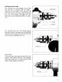
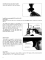
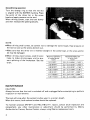
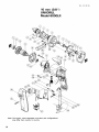
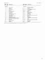
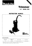
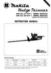
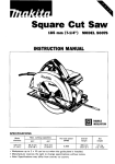
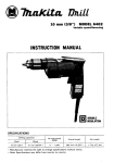
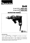
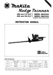
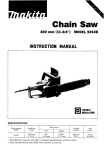
a
Uni-Drill
10 mm (3/8") MODEL 6000LR
INSTRUCTION MANUAL
DOUBLE
INSULATION
SPECIFICAT IONS
CaDacities
No load
(steel)
~~~~~
Machine & wood screws
Self drilling screws
Bolts & Nuts, Tapper
~~~~
1
Overall
length
* Manufacturer reserves the right t o change specifications w i t h o u t notice.
* Note: Specifications may differ from country t o country.
I
Net
weight
IMPORTANT
SAFETY INSTRUCTIONS
(For All Tools)
WARNING: WHEN USING ELECTRIC TOOLS, BASIC SAFETY PRECAUTIONS SHOULD ALWAYS BE FOLLOWED TO
REDUCE THE RISK OF FIRE, ELECTRIC SHOCK, AND PERSONAL INJURY, INCLUDING THE FOLLOWING:
READ ALL INSTRUCTIONS.
1. KEEP WORK AREA CLEAN. Cluttered areas and benches invite injuries.
2. CONSIDER WORK AREA ENVIRONMENT. Don't use power tools in damp
or wet locations. Keep work area well lit. Don't expose power tools to rain.
Don't use tool in presence of flammable liquids or gases.
3. KEEP CHILDREN AWAY. All visitors should be kept away from work area.
Don't let visitors contact tool or extension cord.
4.STORE IDLE TOOLS. When not in use, tools should be stored in dry, and high
or locked-up place - out of reach of children.
5. DON'T FORCE TOOL. It will do the job better and safer at the rate for which
it was intended.
6. USE RIGHT TOOL. Don't force small tool or attachment t o do the job of a
heavy-duty tool. Don't use tool for purpose not intended.
7 . DRESS PROPERLY. Don't wear loose clothing or jewelry. They can be caught
in moving parts. Rubber gloves and non-skid footwear are recommended
when working outdoors. Wear protective hair covering t o contain long hair.
8 . USE SAFETY GLASSES. Also use face or dust mask if cutting operation is
dusty.
9. DON'T ABUSE CORD. Never carry tool by cord or yank it to disconnect from
receptacle. Keep cord from heat, oil, and sharp edges.
I O . SECURE WORK. Use clamps or a vise to hold work. It's safer than using
your hand and it frees both hands t o operate tool.
11. DON'T OVERREACH. Keep proper footing and balance at all times.
12. MAINTAIN TOOLS WITH CARE. Keep tools sharp and clean for better and
safer performance. Follow instructions for lubricating and changing accessories. Inspect tool cords periodically and if damaged, have repaired by authorized service facility. Inspect extension cords periodically and replace if
damaged. Keep handles dry, clean, and free from oil and grease.
2
13. DISCONNECT TOOLS. When not in use, before servicing, and when changing accessories, such as blades, bits, cutters.
14. REMOVE ADJUSTING KEYS AND WRENCHES. Form habit of checking to
see that keys and adjusting wrenches are removed from tool before turning
it on.
15. AVOID UNINTENTIONAL STARTING. Don’t carry plugged-in tool with finger
on switch. Be sure switch is OFF when plugging in.
16. OUTDOOR USE EXTENSION CORDS. When tool is used outdoors, use only
extension cords intended for use outdoors and so marked.
17. STAY ALERT. Watch what you are doing, use common sense. Don’t operate
tool when you are tired.
18. CHECK DAMAGED PARTS. Before further use of the tool, a guard or other
part that is damaged should be carefully checked to determine that it will
operate properly and perform its intended function. Check for alignment of
moving parts, binding of moving parts, breakage of parts, mounting, and any
other conditions ?hat may affect its operation. A guard or other part that
is damaged should be properly repaired or replaced by an authorized service center unless otherwise indicated elsewhere in this instruction manual.
Have defective switches replaced by authorized service center. Don’t use
tool if switch does not turn it on and off.
19. GUARD AGAINST ELECTRIC SHOCK. Prevent body contact with grounded
surfaces. For example; pipes, radiators, ranges, refrigerator enclosures.
20. REPLACEMENT PARTS. When servicing, use only identical replacement parts.
VOLTAGE WARNING: Before connecting the tool to a power source (receptacle,
outlet, etc.) be sure the voltage supplied is the same as that specified on the
nameplate of the tool. A power source with voltage greater than that specified
for the tool can result in SERIOUS INJURY to the user - as well as damage t o
the tool. If in doubt, DO NOT PLUG IN THE TOOL. Using a power source with
voltage less than the nameplate rating is harmful to the motor.
3
ADDITIONAL SAFETY RULES
1. Always be sure you have a firm footing.
Be Sure no one is below when using the tool in high locations.
2. Hold the tool firmly.
3. Keep hands away from rotating parts.
4. When drilling into walls, floors or wherever "live" electrical wires may be
encountered, DO NOT TOUCH ANY METAL PARTS OF THE TOOL!
Hold the tool by the insulated grasping surfaces t o prevent electric shock if
you drill into a "live" wire.
5. Do not leave the tool running. Operate the tool only when hand-held.
6. Do not touch the drill bit or the workpiece immediately after operation: they
may be extremely hot and could burn your skin.
SAVE THESE INSTRUCTIONS.
4
Selecting action mode
1
For drilling, turn the change ring so that
the red dot i s aligned with the DRILL
marking on the collar. If the change ring
will not come all the way, grasp the chuck
and turn the change ring again. Do not
move the red dot beyond the DRILL marking.
For screwdriving, turn the change ring so
that the red dot i s aligned with the SCREW
marking on the collar. Do not move the red
CAUTION :
If you use the tool when the red dot i s not
aligned with either marking, tool damage
may result. Be sure to align properly with
either marking before operation.
I
I
I
5
Installing or removing drill bit or driver bit
CAUTION :
Always be sure that the tool i s switched off and unplugged before installing or removing
the bit.
To install the bit, place it in the chuck as
far as it will go. Tighten the chuck by hand.
Place the chuck key in each of the three
holes and tighten clockwise. Be sure t o
tighten all three chuck holes evenly.
To remove the bit turn the chuck key
counterclockwise in just one hole, then
loosen the chuck by hand.
Tiahten
Chuck key
Switch action
Tool speed i s increased by increasing pressure on the trigger. To start the tool, simply
pull the trigger. Release the trigger t o stop.
For continuous operation, pull the trigger
and then push in the lock button. To stop
the tool from the locked position, pull the
trigger fully, then release it.
CAUTION :
Before plugging in the tool, always check to see that the trigger switch actuates properly
and returns t o the "OFF" position when released.
6
Reversing switch action
This tool has a reversing switch to change
the direction of rotation. Move the reversing switch lever to the "F" position for
clockwise rotation or the "R" position for
counterclockwise.
R e v e r s i n g switch lever
I
CAUTION :
Always check the direction of rotation before drilling.
0
Use the reversing switch only when the tool comes to a complete stop. Changing the
direction of rotation before the tool stop may ruin the tool.
Drilling operation
Turn the change ring so that the red dot is aligned with the DRILL marking.
0
0
Drilling in wood
When drilling holes in the wood, use a wood drill with a guide screw. The guide screw
makes it bore naturally by itself, so you do not need to apply any pressure to the tool.
Drilling in metal
To prevent the bit from slipping when starting a hole, make an indentation with a centerpunch and hammer a t the point t o be drilled. Place the point of the bit in the indentation and start drilling.
Use a cutting lubricant when drilling metals. The exceptions are iron and brass which
should be drilled dry.
CAUTION :
.Pressing excessively on the tool will not speed up the drilling. In fact, this excessive
pressure will only serve to damage the tip of your bit, decrease the tool performance
and shorten the service life of the tool.
.There is a tremendous force exerted on the tool/bit a t the time of hole break through.
Hold the tool firmly and exert care when the bit begins t o break through the workpiece.
0
Always grip the small workpiece firmly with a vise or a holding means.
0 A stuck bit can be removed simply by setting the reversing switch to reverse rotation
in order to back out. However. the tool will pull away easily unless you hold i t firmly
before starting the tool.
7
Screwdriving operation
Turn the change ring so that the red dot
is aligned with the SCREW marking. Place
the point of the driver bit in the screw
head and apply pressure t o the tool.
When driving screws, start the tool slowly
and then increase the speed gradually.
NOTE :
When driving small screws, be careful not to damage the screw heads. Ease pressure on
the tool as soon as the screws bottom out.
0
Make sure that the driver bit i s inserted straight in the screw head, or the screw and/or
bit may be damaged.
When driving wood screws, predrill Pilot
holes to make driving easier and to prevent splitting of the workpiece. See the
chart.
of wood screw
of pilot hole
- 7/64")
- 1/8"1
3.8 (5/32")
2.5 - 2.8 (3/32"
4.5 (11/64")
2.9 - 3.2 (7164"
4.8 (3/16")
3.1 -3.4 ( 1 / 8 " - 9 / 6 4 " )
5.1 (13/64 ')
3.3-3.6
(1/8"-9/64")
6.8 (17164")
4.4-4.7
(11/64"-3/16")
MA1NTENANCE
CAUTION :
Always be sure that the tool i s switched off and unplugged before attempting to perform
inspection or maintenance.
The tool will stop when the carbon brushes wear to a certain length.
When this occurs, both carbon brushes should be replaced.
To maintain product SAFETY and RELlABl LITY, repairs, carbon brush inspection and
replacement, any other maintenance or adjustment should be performed by Makita
Authorized or Factory Service Centers, always using Makita replacement parts.
8
ACCESSORIES
CAUTION :
These accessories or attachments are recommended for use w i t h your Makita t o o l specified in this
manual. The use of any other accessories or attachments might present a risk of injury t o persons. The
accessories or attachments should be used only i n the proper and intended manner.
0
Chuck key SI0
Part No. 763412-5
0 G r i p 26
Part No. 273485-5
9
Oec.-20-83
10 mm (3/8")
UNI-DRILL
Model 6000LR
Note: The switch, noise suppressor and other part configurations
may differ from country to country.
10
US
Apr
MODEL 6000LR
ITEM
NO.
NO.
USED
1
1
1
1
1
1
1
1
1
1
1
1
1
1
1
1
1
2
1
2
1
1
1
-
US
DESCRIPTION
MACHINE
MACHINE
~
~
1
2
3
4
5
6
1
8
9
10
11
12
13
14
15
16
17
18
19
20
21
22
23
$ED
DESCRIPTION
-07-'88
Drill Chuck S10
Change Ring
0 Ring 27
Gear Housing
Flat Washer 16
Spindle
Compression Spring 9
Helical Gear 56
Woodruff Key 3
Gear Shaft
Thrust Needle Bearing 1023
Gear Housing Cover
Flat Washer 6
Gear Complete 1 5 - 3 8
Flat Washer 8
Flat Head Screw M6x13
Pan Head Screw M4x45 lWith Washer1
Pan Head Screw M4x55 [With Washerl
Name Plate
Rivet 0 - 5
Ball Bearing 608LB
Rubber Pin 4
Fan 58
24
1
25
26
1
2
21
28
29
1
1
1
1
1
1
2
2
2
1
1
1
30
31
32
33
34
35
38
39
40
41
42
43
44
45
46
102
3
1
1
2
1
1
1
ARMATURE ASSEMBLY
[With Item 21 23 311
Baffle Plate
Hex Bolt M4x45 [With Washerl
FIELD ASSEMBLY
Leaf sprmg
Hook
Motor Housing
Ball Bearing 627L8
Rubber Pin 4
Carbon Brush
Brush Holder
Pan Head Screw M4x14 iWith Washerl
Switch
Dust Cover
Handle Cover
Pan Head Screw M4x28 (With Washer1
Switch
Cord
Pan Head Screw M4x18 IWith Washerl
Strain Relief
Cord Guard
Grip 26
Note The switch and other Dart Specifications may differ f r o m Country t o country
11
1’
MAKITA LIMITED ONE YEAR WARRANTY
Warranty Policy
Every Makita tool is thoroughly inspected and tested before leaving the factory. It is warranted to
be free of defects from workmanship and materials for the period of ONE YEAR from the date of
original purchase. Should any trouble develop during this one-year period, retum the COMPLETE
tool, freight prepaid, to one of Makita’s Factory or Authorized Service Centers. If inspection shows
the trouble is caused by defective workmanship or material, Makita will repair (or at our option,
replace) without charge.
This Warranty does not apply where:
repairs have been made or attempted by others:
0 repairs are required because of normal we= and tear:
The tool has been abused, misused or improperly maintained;
0 alterations have been made to the tool.
IN NO EVENT SHALL MAKITA BE LIABLE FOR ANY INDIRECT, INCIDENTAL OR CONSEQUENTIAL DAMAGES FROM THE SALE OR USE OF THE PRODUCT. THIS DISCLAIMER
APPLIES BOTH DURING AND AFTER THE TERM OF THIS WARRANTY.
MAKITA DISCLAIMS LIABILITY FOR ANY IMPLIED WARRANTIES, INCLUDING IMPLIED
WARRANTIES OF “MERCHANTABILITY” AND “FITNESS FOR A SPECIFIC PURPOSE,”
AFTER THE ONE-YEAR TERM OF THIS WARRANTY.
This Warranty gives you specific legal rights, and you may alp0 have other nghts which vary from
state 10 state. Some states do not allow the exclusion or limitation of incidental or consequential
damages, so the above limitation or exclusion may not apply to you. Some states do not allow
limitation on how long an implied warranty lasts, so the above limitation may not apply to you.
Makita Corporation
3-11-8,Sumiyoshi-cho,
Anjo, Aichi 446 Japan
883490A062
PRINTED IN JAPAN
1991 - 6 - N