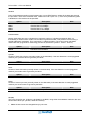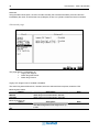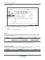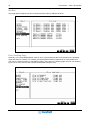
1
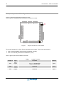
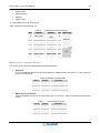
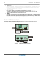
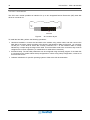
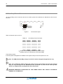
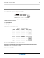
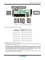
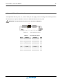
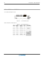
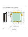
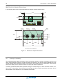
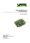
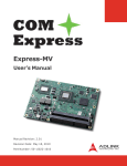
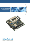
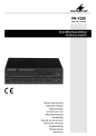
EmbeddedDNA ® CPU-1461 PC/104-Plus CPU Module User’s Manual Rev. 1.0 Jul. 2005 COPYRIGHT 1994-2005 Eurotech S.p.A. All Rights Reserved. 2 PC/104-Plus – CPU-1461 Module This manual is intended for engineers and programmers. It contains technical specifications, as well as describes the connectors and how to properly use and configure the product. Via J. Linussio 1 33020 AMARO (UD) ITALY Phone: +39 0433 485 411 Fax: +39 0433 485 499 Web: http://www.eurotech.it e-mail: [email protected] NOTICE Although all the information contained herein has been carefully verified, Eurotech S.p.A. assumes no responsibility for errors that might appear in this document, or for damage to property or persons resulting from an improper use of this manual and of the related software. Eurotech S.p.A. reserves the right to change the contents and form of this document, as well as the features and specifications of its products at any time, without notice. Trademarks and registered trademarks appearing in this document are the property of their respective owners PC/104-Plus – CPU-1461 Module 3 Conventions The following table lists conventions that are used throughout this guide. Icon Notice Type Information note Warning Description Important features or instructions Information to alert you to potential damage to a program, system or device or potential personal injury Environmental safety When disposing the equipment, we suggest separating all of its components when possible, and disposing of them in accordance with local waste disposal legislations. Be sure to dispose of used batteries as required by local waste disposal legislation. Never throw batteries into a fire (risk of explosion) or household garbage can. Contents Conventions ................................................................................................................................................... 3 Environmental safety...................................................................................................................................... 3 Contents ........................................................................................................................................................... 5 Chapter 1 Product Overview ...................................................................................................................... 7 Product Definition........................................................................................................................................... 8 Chapter 2 Jumper Description ................................................................................................................... 9 Jumper Layout and Configuration................................................................................................................ 10 Chapter 3 Connectors Description .......................................................................................................... 11 Connectors Layout ....................................................................................................................................... 12 How to connect the CPU-1461 to other PC/104 & PC/104-Plus devices: the stack assembly ................... 13 J4 for Multifunction and VGA ....................................................................................................................... 14 Multifunction Connector Section............................................................................................................ 15 The Eurotech Multifunction Adapter ...................................................................................................... 16 VGA Section .......................................................................................................................................... 17 J5 IDE Connector......................................................................................................................................... 18 J7 for USB 2.0 (Ports 5 and 6)..................................................................................................................... 19 J9 Auxiliary Power Connector...................................................................................................................... 20 J14 for USB 1.1 (Ports 7 and 8) and Audio-CODEC ................................................................................... 21 The Eurotech USB & AC97-Audio Codec Adapter ............................................................................... 21 J16 for USB 2.0 (Ports 1to 4)....................................................................................................................... 23 J17 for SERIAL1 and SERIAL2 ................................................................................................................... 24 J20 for Ethernet............................................................................................................................................ 25 The Eurotech Ethernet Transceiver ...................................................................................................... 26 6 PC/104-Plus – CPU-1461 Module Chapter 4 The Set-up Program................................................................................................................. 27 The Set-up pages......................................................................................................................................... 30 General Page ........................................................................................................................................ 30 Devices Page ........................................................................................................................................ 32 Communications Page .......................................................................................................................... 34 Primary and Secondary ATAPI Page .................................................................................................... 36 Advanced page...................................................................................................................................... 38 PCI Advanced Page .............................................................................................................................. 39 ISA Bus.................................................................................................................................................. 40 Error Handling Page.............................................................................................................................. 40 Chapter 5 Watch Dog Timer ..................................................................................................................... 43 What is a Watch Dog? ................................................................................................................................. 44 How to use the Watch Dog .......................................................................................................................... 44 Use the System BIOS INT 52h functions .............................................................................................. 44 Directly accessing Watch Dog I/O mapped registers............................................................................ 45 Chapter 6 Troubleshooting....................................................................................................................... 47 Common Problems and Solutions ............................................................................................................... 48 Troubleshooting a PC/104 System .............................................................................................................. 48 Technical/Sales Assistance ......................................................................................................................... 48 Returning For Service .................................................................................................................................. 49 Appendix ........................................................................................................................................................ 53 A.1 Electrical and Environmental Specifications ..................................................................................... 54 Operating Characteristics...................................................................................................................... 54 Absolute Maximum Ratings................................................................................................................... 55 MTBF (Mean Time Between Failures) .................................................................................................. 55 A.2 Mechanical Dimensions .................................................................................................................... 56 USB Audio Codec Dimensions.............................................................................................................. 57 Ethernet Adapter Dimensions ............................................................................................................... 57 Multifunction Adapter Dimensions......................................................................................................... 58 A.3 Safety Summary................................................................................................................................ 58 Ground the Instrument .......................................................................................................................... 59 Do Not Operate in an Explosive Atmosphere ....................................................................................... 59 Keep Away From Live Circuits .............................................................................................................. 59 Use Caution When Exposing or Handling the CRT .............................................................................. 59 Do Not Substitute Parts or Modify Equipment....................................................................................... 59 Observe Dangerous Procedure Warnings ............................................................................................ 59 Flammability .......................................................................................................................................... 59 EMI Caution........................................................................................................................................... 59 CE Notice .............................................................................................................................................. 59 Disclaimer of Warranty .......................................................................................................................... 60 Notice .................................................................................................................................................... 60 Reliability ............................................................................................................................................... 60 Life Support Policy ................................................................................................................................ 60 Glossary ......................................................................................................................................................... 61 Acronyms and Abbreviations....................................................................................................................... 67 Chapter 1 Product Overview The CPU-1461 is a reliable Celeron PC/104-Plus embedded module with 6 fast USB 2.0 ports For a complete list of related accessories, as well as latest BIOS and drivers, please go to our web site: www.eurotech.it In the following paragraphs you will find a description of the CPU-1461characteristics. 8 PC/104-Plus – CPU-1461 Module Product Definition Architecture: PC/104-Plus 2.0 compliant Processor: PentiumIII® 800MHz, 256KB L2 cache, 133MHz PSB Chipset: Intel® 815E Memory: 256MB SDRAM soldered on board Operating Systems: WinCE®, VxWorks®, Linux®, QNX® BIOS Flash: 1MB Flash EPROM Interfaces: IDE Controller UltraDMA 2x Serial: 1 RS232, 1 RS232/422/485 2x USB 1.1 6x USB 2.0 Ethernet (10/100 Mbps) VGA Video Controller Auxiliary Power AC97 Keyboard and Mouse Bus: PC/104-Plus (PCI) PC/104 (ISA) Watchdog: 2-255 sec./min. Power Supply: +5V DC Chapter 2 Jumper Description This chapter shows the layout of the jumpers and explains how to set them up. 10 PC/104-Plus – CPU-1461 Module Jumper Layout and Configuration Figure 1 shows the jumper layout of the CPU-1461. The jumpers are indicated as JP followed by the jumper's number. JP3 JP2 JP1 Figure 1. Jumpers on the CPU-1461 module Three 2-pin jumpers (JP1, JP2 & JP3) are located on the module. They can be set as follows: ¾ Pins connected together (which will be indicated as ‘Closed’) ¾ Pins not connected (which will be indicated as ‘Open’) Table 1 gives a quick cross-reference for them. Table 1. Jumper # Type JP1 2 pin jumper JP2 JP3 2 pin jumper 2 pin jumper Jumper Functions Function IDE LED Pin 1 (-): cathode LED Pin 2 (+): anode LED Default Reserved Open Reserved Open Open Chapter 3 Connectors Description This chapter provides a brief description of the CPU-1461 module’s connectors, their positions and functions. 12 PC/104-Plus – CPU-1461 Module Connectors Layout Figure 2 shows the connectors with their layout and function(s). J14 J16 J17 J1 J2 J3 J7 J20 J4 J5 Figure 2. Connector layout Note: in figure 2, a red square pad indicates pin 1 of each connector. PC/104-Plus – CPU-1461 Module 13 Table 2 lists the name of the connectors with their function: Table 2. Connector J1-J2 J3 J4 J5 J7 J9 J14 J16 J17 J20 Connector Functions Function ISA BUS (Bottom Side Only) PCI BUS (Bottom Side Only) Multifunction, VGA IDE/DOM USB 2.0 (Ports 5 and 6) Aux. power USB 1.1 (Ports 1 and 2), AUDIO CODEC USB 2.0 (Ports 1..4) Serial Ports 1and 2 Fast Ethernet (10/100Mbps) Qty of pins 18 44 8 12 20 16 18 8 Format 9x2 22x2 8x1 6x2 10x2 8x2 9x2 8x1 Pitch (mm) 2.00 2.00 2.00 2.54 2.00 2.00 2.00 2.00 How to connect the CPU-1461 to other PC/104 & PC/104-Plus devices: the stack assembly The ISA and PCI Bus connectors of the CPU-1461 are located on the bottom side of the module only, and are designed to allow the connection on the top position of the stack formed by other PC/104 and/or PC/104Plus devices. We recommend you to follow the procedure below ensuring that stacking of the modules does not damage connectors or electronics parts. Always use appropriate antistatic precautions when handling boards 1. Turn off all power to the PC/104 computer and its peripheral devices. 2. Select and install standoffs to properly position the module on the PC/104 stack. 3. Remove the module from its antistatic bag. 4. Check that keying pins in the bus connector are properly positioned. 5. Check the stacking order; make sure an XT bus card are not placed between two AT bus cards as this will interrupt the AT bus signals. 6. Hold the module by its edges and orient it so that the bus connector pins line up with the matching connector on the stack. 7. Using even pressure press the module onto the PC/104 stack. 14 PC/104-Plus – CPU-1461 Module Figure 3 shows a module stack with the CPU-1461 on the top of two PC/104-Plus modules. If standard PC/104 modules are used in the stack, they must be the lowest modules because they will normally not include the PCI bus. An adapter module must be used. CPU-1461 Carrier Module Figure 3. The Module Stack Do not force the module onto the stack! Wiggling the module or applying too much pressure may damage it. If the module does not readily press into place, remove it, check for bent pins or out-of-place keying pins, and try again. J4 for Multifunction and VGA This connector enables the connection of a speaker, keyboard, mouse, battery and VGA monitor to the CPU1461. J4 Multifunction, VGA Figure 4. J4 Connector Layout The connector implements the following functions: ¾ MULTIFUNCTION SECTION (from pin 1 to pin 9) Keyboard PS/2 Mouse PC/104-Plus – CPU-1461 Module ¾ System reset External battery Speaker Power button 15 VGA monitor (from pin 10 to pin 18) Table 3 shows the connector pin out. Table 3. J4 Multifunction/VGA connector PIN SIGNAL 1 GND_SRV 3 5 7 9 11 13 15 17 KBDAT MSDAT BAT_IN RES_PB_IN HSYNC RED_VGA DDC1_SCL GNDA_VGA SIGNAL PIN FUNCTION VDD_SRV 2 (+5V) KBCLK 4 MULTIF. MSCLK 6 SPKR 8 GND_VGA 10 VSYNC 12 GREEN_VGA 14 VGA DDC0_SDA 16 BLUE_VGA 18 Multifunction Connector Section This section of the connector implements the following functions: Keyboard An AT compatible keyboard can be connected to the module through connector J4. Table 4 lists the pin-out of connector J4. Table 4. Keyboard connector table Pin # 1 2 3 4 Signal GND +5V KBDAT KBCLK Function Ground signal Power supply Keyboard data Keyboard clock Mouse Connector Section A PS/2 compatible mouse can be connected to the J4 connector. Table 5 shows the pin-out for the mouse Table 5. Pin # 1 2 5 6 J4 for Mouse connector Signal GND +5V MSDAT MSCLK Function Ground signal Power supply Mouse data Mouse clock 16 PC/104-Plus – CPU-1461 Module System reset The connection of the multifunction connector pin 9 to ground performs a hardware reset of the module. It is possible to use an external push-button (normally open) to manually reset the system. The reset signal is “de-bounced” on the board. External Battery Pin 7 of the multifunction connector allows the connection of an external backup battery. If you connect a battery, then the voltage must be between 3.0V and 3.9V. This battery is used when the system is powered down to preserve the Real Time Clock data. The typical battery consumption with the module off is 7uA. Speaker A transistor that supplies 0.1W to an external speaker controls these outputs. A transistor amplifier buffers the speaker signal. Use a small general-purpose 2” or 3” permanent magnet speaker with an 8Ω voice coil. The audio output is based on two signals: one come from the output of Timer 2, and the other come from I/O port 61h compliant with the AT Standard. The Eurotech Multifunction Adapter The Eurotech Multifunction Adapter simplifies the connection of mouse and keyboard with two PS/2 connectors, a speaker, battery and a reset pushbutton. Battery Speaker J6 J1 J5 J4 To Multif. Conn. Of CPU Board (Mouse sign.) Not used To Multif. Conn. of CPU Board Power Led J3 J2 S1 Mouse Keyboard Reset Pushbutton Figure 5. Spkr Led Multifunction Adapter (both sides) PC/104-Plus – CPU-1461 Module 17 9 Table 6. BATT_IN (to J4 PIN 7) J4 To CPU J4 Connector PIN # SIGNAL SPKR (to J4 PIN 8) 1 +5V (to J4 PIN 2) 2-8 RES_PB_IN (to J4 PIN 9) 3 N.C. 4-10 KBDAT (to J4 PIN 3) 5 KBCLK (to J4 PIN 4) 6 GND (to J4 PIN 1) 7 Table 7. PIN # 1 2 3 4 J6 To CPU J4 Connector (Mouse signals) SIGNAL +5V (to J4 PIN 2) MSCLK (to J4 PIN 6) GND. (to J4 PIN 1) MSDAT (to J4 PIN 5) VGA Section The CPU-1461 integrates a high-performance 2D graphics accelerator Supported CRT-VGA Video Resolutions Table 8 shows supported CRT Display Modes1 Table 8. Resolution 640x480 320x200 320x240 352x480 352x576 400x300 512x384 640x400 640x480 720x480 720x576 800x600 1024x768 1152x864 1280x720 1280x960 1280x1024 Partial list of Display Modes Supported Bits Per Pixel (frequency in Hz) 8-bitIndexed 16-bit 24-bit 70 70 70 70 70 70 70 70 70 70 70 70 70 70 70 70 70 70 70 70 70 60, 70, 72, 75, 85 60, 70, 72, 75, 85 60, 70, 72, 75, 85 75, 85 75, 85 75, 85 60, 75, 85 60, 75, 85 60, 75, 85 60, 70, 72, 75, 85 60, 70, 72, 75, 85 60, 70, 72, 75, 85 60, 70, 72, 75, 85 60, 70, 72, 75, 85 60, 70, 72, 75, 85 60, 70, 72, 75, 85 60, 70, 72, 75, 85 60, 70, 72, 75, 85 60, 75, 85 60, 75, 85 60, 75, 85 60, 75, 85 60, 75, 85 60, 75, 85 60, 70, 72, 75, 85 60, 70, 72, 75, 85 60, 70, 72, 75, 85 18 PC/104-Plus – CPU-1461 Module J5 IDE Connector The CPU-1461 module provides an interface for up to two Integrated Device Electronics (IDE) hard disk drives on connector J5. J5 IDE/DOM Figure 6. J5 Connector layout To install the hard disk, perform the following operations: ¾ Hardware installation. Connect the hard disk to the module using a data cable, and then connect the hard disk to the power supply according to the device’s specifications. Make sure that pin 1 of connector J5 and pin 1 of the drive or drives are correctly connected. Pin 1 of the interface cable is usually indicated by a stripe along the edge of the cable. If two hard disks need to be connected, they must be configured for common operation (i.e. master/slave or cable select connection). ¾ IDE BIOS Setup. The hard disk parameters can be configured using the Setup program. If the hard disk is connected to the module without setup configuration or with a wrong setup configuration, a time-out of a few minutes occurs. ¾ Software initialization for specific operating systems. Refer to the OS documentation. PC/104-Plus – CPU-1461 Module 19 J7 for USB 2.0 (Ports 5 and 6) J7 is used for USB 2.0, ports 5 & 6. Each port can supply up to 2A J7 USB 5, 6 Figure 7. J7 Connector Layout Table 9. J7 Connector pin out PIN# 1 2 3 4 5 6 7 8 SIGNAL FUNCTION VDD_USB5 USB5USB 5 USB5+ GND_USB_5 VDD_USB_6 USB6USB 6 USB6+ GND_USB_6 Note: To establish a USB connection, no transceiver is required. 20 PC/104-Plus – CPU-1461 Module J9 Auxiliary Power Connector J9 is an auxiliary power connector and can be used to power the module as an alternative to the PC/104Plus bus. J9 Auxiliary Power Figure 8. J9 Connector layout Table 10 shows the pin out for J9. Table 10. J9 Auxiliary Power Connector PIN # SIGNAL SIGNAL PIN # GND VDD 1 2 N.C. +12v 3 4 -5V -12V 5 6 GND VDD 7 8 N.C. PWRBTN# 9 10 (1) (2) +5VSB PSON# 11 12 (1) +5VSB: +5 Volts-Always from the ATX Power supply (2) PSON#: Power-On command to ATX Power supply Power button (input) If the soft power management is enabled, a low signal in this pin turns the system on or off. Note. The VSB (Volt Stand-By) voltage is useful for Power management applications only. Note. The +12VDC and -5VDC voltages are neither used nor generated by the CPU-1461 module: they are only conveyed on the PC/104-Plus bus (connector J1) and can be used by other devices or modules that are stacked onto the CPU module. WARNING! IMPROPER CONNECTION OF THE POWER SUPPLY WILL RESULT IN SERIOUS DAMAGE TO THE MODULE. PC/104-Plus – CPU-1461 Module 21 J14 for USB 1.1 (Ports 7 and 8) and Audio-CODEC J14 is used for USB 1.1, ports 7 & 8 and the Audio CODEC. J14 1 2 Figure 9. J14 Connector Layout It implements the following functions: ¾ CODEC Audio port ¾ USB 1.1 port 7 ¾ USB 1.1 port 8 Table 11 shows the J14 connector pin out. Table 11. PIN # 1 3 5 7 9 SIGNAL SPKR SDOUT GND SDIN0 RST 11 GND 13 15 17 19 USB7USB7+ GND GND J14 Connector pin out SIGNAL SDIN1 CDC_EN# GND BITCLK SYNC USB Over Current1# USB8USB8+ VDD VDD PIN # PORT 2 4 6 8 10 Audio Codec 12 14 16 18 20 USB 7, 8 The Eurotech USB & AC97-Audio Codec Adapter Before using a USB and/or an Audio Device, the Eurotech USB/AC97-Audio Codec Adapter must be connected to the CPU board. The connection between the Eurotech adapter and the CPU board is established by a cable set provided with the adapter. Figure 10 shows this adaptor. 22 PC/104-Plus – CPU-1461 Module Aux IN SpkPhone IN/OUT To J14 CPU Board Connector Aux IN Figure 10. USB 7 USB 8 SPK OUT Line OUT Line IN Mic IN CD IN USB/AC97-AudioCODEC Adapter Table 12 shows the adapter connectors description. Table 12. USB/AC97-AudioCODEC Connectors Connector# J1 J2 J3 J4 J5 J6 J7 J8 J9 J10 J11 Function USB0 USB1 Microphone IN Line IN Speaker OUT Line OUT CD IN Aux IN Aux IN Speakerphone IN/OUT To CPU Board Connector (J4) This adapter is composed of 2 functional sections: ¾ USB section, with 2 USB ports which are EMI protected and filtered, and can also supply power to the peripheral device connected (5V, 500mA); ¾ Audio section, which is equipped with the LM4549 National, an AC97 compliant I.C. The AC97 architecture separates the analog and digital functions of the PC audio system allowing both for system design flexibility and increased performance. The LM4549 is an Audio CODEC for PC systems, which is fully PC98 compliant and performs the analog intensive functions of the AC97 Rev2.1 architecture. Using 18-bit Sigma-Delta A/D’s and D/A’s, the LM4549 provides 90dB of Dynamic Range. The Audio section of this board provides 4 stereo inputs, 1 microphone input, 1 stereo line input, 1 stereo earphone output (200mW) and 1 speakerphone. PC/104-Plus – CPU-1461 Module 23 J16 for USB 2.0 (Ports 1to 4) J16 implements USB 2.0 ports 1, 2, 3 and 4. Each port can supply current according to the following scheme: The total amount of power available for use is 2A distributed between the four ports WARNING: The total amount of power must not exceed 2 Amperes J16 Figure 11. Table 13. J16 Connector Layout J16 Connector pinout PIN # SIGNAL VDD 1 USB43 VDD_USB 3, 4 5 USB37 VDD 9 USB211 VDD 13 USB115 SIGNAL GND USB4+ GND USB3+ GND USB2+ GND USB1+ PIN # 2 4 6 8 10 12 14 16 24 PC/104-Plus – CPU-1461 Module J17 for SERIAL1 and SERIAL2 J17 is used for Serial ports 1 and 2. J17 Figure 12. J17 Connector Layout Table 14 shows the connector pin out. Table 14. PIN # 1 3 5 7 9 11 13 15 17 SIGNAL DCD1 RX1 TX1 DTR1 GND DSR2 RTS2 CTS2 RI2 J17 Connector pin out SIGNAL DSR1 RTS1 CTS1 RI1 DCD2 RX2 TX2 DTR2 GND PIN # 2 4 6 8 10 12 14 16 18 FUNCTION Serial 1 Serial 2 PC/104-Plus – CPU-1461 Module 25 J20 for Ethernet J20 is used the Ethernet connection. J20 Ethernet Figure 13. J20 Connector Layout Table 15 shows the J20 connector pin out. Table 15. PIN # 1 2 3 4 5 6 7 8 J20 Connector pin out SIGNAL +3.3V ACTIVITY LED RX+ RXLINK LED GND TX+ TX- 26 PC/104-Plus – CPU-1461 Module The Eurotech Ethernet Transceiver To establish an Ethernet connection an Ethernet Transceiver must be used. Eurotech supplies a Transceiver that can be placed between the J20 connector of the CPU board and the network cable. To CPU Board NetConnector RJ45 Connector Figure 14. The Eurotech Ethernet Adapter The green led is fixed, and signals the correct connection of the module. The yellow led blinks when there is activity (data IN/OUT) on the net connection. With RJ45 connectors, only twisted pair cables can be used. Important Note. Connection to a 100BASE-TX hub for 100 Mbps operation requires the use of Cat.5 Unshielded Twisted-Pair (UTP) cable or Cat.5 Shielded Twisted-Pair (STP) cable. The maximum length between the 100BASE-TX hub and the adapter is 100 meters. Connection to a 10BASE-T hub for 10 Mbps operation requires a Cat.3, 4 or 5 UTP cable or Cat.5 STP cable. The preferred maximum cable length between the CPU module and the Ethernet adapter is 10 cm (4”) . Chapter 4 The Set-up Program This chapter explains how to use and modify the setup options. These options allow configuring properly the CPU board. Note. The Setup Program can be improved to match the technical requirements. To enter in the Setup Program reboot or switch-on your module and then press the “F2” key. After waiting a few seconds the main menu will appear. The Main menu of the set-up program shows a list of options that are available. A highlight illustrates which option is currently selected. 28 PC/104-Plus – CPU-1461 Module Use the cursor arrow keys to move the highlight to other options. When an option (i.e.: General) is highlighted, it is possible to execute it by pressing the “Enter” key. A table of items will be displayed on the right side of the screen. Now it is possible to select among several items (i.e.: Time, Date, Floppy Disk 1,… ) using the arrow keys and the “Enter” key. When an item is highlighted, it is possible to change its value by pressing the “PageUp” and “PageDown” keys. Time and Date items are set using the keys “PageUp” and “PageDown” and the keys from “0” to “9”; press “Enter” to confirm. To correct errors press the “BackSpace” key. Press the “ESC” key to return to the items of the Main menu. Select “Quit” to exit from the Setup program. PC/104-Plus – CPU-1461 Module 29 The follow screen will be displayed: Select with the “ENTER” key the first option “Save data to Flash” to store the parameters into the EEPROM. Select Discard changes to leave unaltered the previous stored parameters. 30 PC/104-Plus – CPU-1461 Module The Set-up pages The Set-up Program is composed of several pages. They are listed below: ¾ General ¾ Devices ¾ Communications ¾ Primary ATAPI ¾ Secondary ATAPI ¾ Advanced ¾ PCI Advanced ¾ ISA Bus ¾ Error Handling General Page This page contain settings for the following devices: Time Date (for the Real Time Clock) Floppy Disk 1(*) Floppy Disk 2(*) Keyboard Quick Boot Boot Try Sequence (*) The CPU-1461 Module can perform Floppy Disk 1 and 2 options only if used together with an Add-on module where floppy disk ports are available. PC/104-Plus – CPU-1461 Module 31 Time The time is displayed in standard format: hh mm ss (hours - minutes - seconds). Date The date is display in standard format: MMM DD YYYY (month - day - year). Floppy disks The floppy disks are numbered starting from one and the BIOS maps these drivers starting form the letter “A”. Note: when the boot sequence starts from floppy disk number one (DOS letter “A”), any device selected as floppy disk 1 can be a bootable disk. Obviously this device must represent a real bootable disk, with a proper boot sector and containing a valid O.S. All the floppy disks can be configured with the same options. The CPU-1461 Module can perform floppy disk options only if used together with an Add-on module where floppy disk ports are available: Option None 360 KB 1.2 MB 720 KB 1.44 MB Integrated SSD Description No floppy disk selected Floppy disk 5 ¼ - size 360 Kbytes Floppy disk 5 ¼ - size 1.2 Mbytes Floppy disk 3 ½ - size 720 Kbytes Floppy disk 3 ½ - size 1.44 Mbytes On-board Flash EEPROM Note Common used size Always available on all boards Keyboard If the keyboard is not really necessary in the system, you can disable it. In this way the system can bootstrap without error. Option Not Present Present Description Keyboard presence ignored BIOS look for keyboard Note Useful for embedded systems Quick Boot With quick boot enabled, the system takes less than 5 seconds for a bootstrapping. This improvement is obtained to the disadvantage of BIOS tests (the setup must be correct and the peripheral must be connected to the module and ready at the boot); in particular the following test are skipped: System memory pattern test Keyboard detection Floppy disk presence (seek test) RTC time test Option Disabled Enabled Description Normal BIOS test are used Reduce set of BIOS test are used Note 32 PC/104-Plus – CPU-1461 Module Boot Try Sequence The Boot Try Sequence allows exchanging the boot disk order among Floppy Disk 1, Hard Disk 1, CD-ROM and NET. Option FD1 / HD1 / NET NET / FD1 / HD1 HD1 / FD1 / NET CD-ROM / FD1 / HD1 Description Bootstrap order: FD1, HD1, NET Bootstrap order: NET, FD1, HD1 Bootstrap order: HD1, FD1, NET Bootstrap order: CD-ROM, FD1, HD1 Devices Page This page controls all the on-board system-devices; in particular: Floppy Disk Controller Primary EIDE Secondary EIDE Video Controller AC97 Controllers Network PS/2 Mouse Bridge MAC Address Floppy Controller The Floppy controller can be enabled or disabled Note PC/104-Plus – CPU-1461 Module 33 Primary and secondary EIDE This option enables or disables the on-board EIDE hard disk controllers. For example, if an external hard disk controller needs to be used, the internal one must be disabled. Option Disabled Enabled Description Disable the on-board hard disk controller Enable the on-board hard disk controller Note An external controller can be used Video Controller The on-board Video Controller can be automatically disabled if another one is found in the system; otherwise the on-board video controller can be forced anyway, even if another controller is present. Option Replace with Add-On if any Always use Integrated Description If an external controller is found, it is used In any case the on-board controller in used Note AC97 Controller The on board AC97 controller can be enabled or disabled Network In PCI system the user can manually enables or disables the on-board network adapter. Option Disabled Enabled Device only Enabled device and Firmware Description Disable the on-board network controller Enable the on-board network controller Enable the on-board network controller and the Firmware in order to allow the boot from network Note PS/2 Mouse If not used, the PS/2 mouse can be disabled. In this way the interrupt IRQ 12, normally reserved for mouse, is free for PCI bus or other devices. • Note: the interrupt reserved for mouse is fixed (IRQ 12); it is displayed for information only. Option Description Note Disable the on-board mouse controller Disabled Enable the on-board mouse controller Enabled Bridge MAC Address This option allows configuring the hexadecimal values of the Bridge MAC Address. 34 PC/104-Plus – CPU-1461 Module Communications Page This page concerns all the on-board communication interfaces: Serial Port1 • Mode • VP2000 and VT100 Serial Port2 • Mode • VP2000 and VT100 Parallel Port • Mode • VP2000 and VT100 Serial Ports 1 and 2 Serial Port 1 is RS232 only. Serial Port 2 is RS232/422/485. Serial Port Address (the same options for both Serial Ports) Option Disabled 3F8h 2F8h 3E8h 2E8h Description Disable the serial port Serial Port address selected at 3F8h Serial Port address selected at 2F8h Serial Port address selected at 3E8h Serial Port address selected at 3E8h Note PC/104-Plus – CPU-1461 Module 35 • Note: not all consecutive IRQ numbers from 3 to 15 can be used; to help the selection, the Setup program displays legal IRQ numbers only. • Note: the IRQ is shared: the ports can use the same IRQ number. VP2000 and VT100 With this option the user can enable or disable the VP2000 and VT100 functionality serial ports. Parallel Port Parallel Port Address Option Disabled 0378h 0278h Description Disable the serial port Parallel Port address selected at 378h Parallel Port address selected at 278h Note Description No IRQ selected for the Parallel Port IRQ 3 selected IRQ 4 selected ... IRQ 12 selected Note Parallel Port IRQ Number Option None 3 4 ... 12 • Note: not all consecutive IRQ numbers from 3 to 12 can be used; to help the selection, the Setup program displays legal IRQ numbers only. Parallel DMA Channel Option None 0 1 3 Description No DMA selected for the Parallel Port DMA Channel 0 selected DMA Channel 1 selected DMA Channel 3 selected Note Parallel Port Mode The user, according the parallel device connected to the interface, can choose The Parallel Port Mode. The default mode is Bidirectional. Option Printer Bi-directional PP FIFO ECP EPP Description Standard mono-directional printer interface Bi-directional printer interface EPP and SPP mode ECP mode EPP mode VP2000 With this option the user can enable or disable the VP2000 functionality on the parallel port. Note 36 PC/104-Plus – CPU-1461 Module Primary and Secondary ATAPI Page This option concerns mass storage devices using a standard EIDE interface. The CPU board has two EIDE controllers, so the ATAPI Units can be separated in two parts: ATAPI Primary and ATAPI Secondary. In any case the options are the same. • Note: ATAPI (or EIDE) devices can be both hard disks and CD_ROM devices or, sometimes, storage tape-units. • Note: each EIDE interface supports two peripherals, called master unit and slave unit. Remember to select as master unit a bootable disk (containing any valid O.S.). ATAPI unit type Option None Auto LBA CHS CD-ROM Other Description No unit selected Unit auto-detection LBA unit selected CHS unit selected CD-ROM unit selected Other unit selected Note • Note: when the Auto feature is selected, the BIOS ignores any other data (like Mode, Cyls, Head, etc.). Use this option for the most of hard disks or other ATAPI devices. • Note: LBA and CHS are two different types of ATAPI units addressing mode. The first one is normally used with modern hard disks, from 512 Kbytes to above 8 Gbytes in size. For both modes, the user should know the physical hard-disk structure in terms of Cylinders, Heads and Sectors. For easy use of any kind of disk, the Auto option is preferable. • Note: to speed-up the bootstrap select the option None for unused ATAPI devices. PC/104-Plus – CPU-1461 Module 37 PIO Mode PIO is a special data-transfer system between two or more EIDE devices, where all the data pass through the processor. There are five transfer rates, called PIO mode n (with n=0..4). If the Auto (autodetect) option is disabled, the PIO mode must be specified. Option PIO-0 PIO-1 PIO-2 PIO-3 PIO-4 Description Transfer Rate of 3.3 MBps Transfer Rate of 5.2 MBps Transfer Rate of 8.3 MBps Transfer Rate of 11.1 MBps Transfer Rate of 16.6 MBps Note Translation Mode Modern hard-disks have more cylinders than maximum number of cylinders permitted by DOS, so, theoretically, a DOS machine couldn’t use a modern big-sized hard disk. This problem is solved using a special addressing mechanism. This “mechanism” is called translation. The most common translation method are LBA (Logical Block Addressing) and ECHS (Enhanced Cylinders - Heads - Sectors). Option Description Note LBA translation Extended CHS translation LBA ECHS Cylinders Number of hard-disk cylinders (normally written on the disk label). If the auto-detection is used (suggested method!), the cylinders value is ignored by the BIOS. Option 0..65536 Description Number of cylinders Note Heads Number of hard-disk heads (normally written on the disk label). If the auto-detection is used (suggested method!), the heads value is ignored by the BIOS. Option 0..64 Description Number of heads Note Sect/Tr Number of sectors per track (normally written on the disk label). If the auto-detection is used (suggested method!), the sectors value is ignored by the BIOS. Option 0..255 Description Number of sectors per track Note Size (MB) This is the hard-disk size, in Mbytes, calculated by the BIOS, using either the autodetect method or the user hand-written values (for cylinders, heads and sectors). • Note: the size cannot be changed directly by the user. 38 PC/104-Plus – CPU-1461 Module Detect Now Using the Detect Now option, the user can start manually the hard-disk autodetect procedure and see immediately the result, as well as the size (in Mbytes), in terms of cylinders, heads and sectors numbers. Advanced page This page allow the configuration of: • Legacy PnP Support • Watch Dog start at boot • Watch Dog Timeout Legacy PnP Support can be enabled or disabled. The watch Dog starts at Boot and, if enabled, when the selected timeout expires, resets the CPU. Watch Dog starts at Boot Option Disabled Minutes Seconds Description Watch Dog disabled Watch Dog unit of measurement: Minutes Watch Dog unit of measurement: Seconds Note Watch Dog timeout (>=2) Option 2 … 255 Description The Watch Dog timeout can range from 2 up to 255 Note PC/104-Plus – CPU-1461 Module 39 PCI Advanced Page This page can be used to specify some advanced PCI options like: ISA IRQ Latency Time (both for CPU and devices) ISA IRQ This option makes possible any assignment between an ISA IRQ (for the Interrupt Controller) and the four PCI IRQ lines A, B, C and D. Obviously not all the assignments are legal, but the Setup programs shows only the available ISA interrupts. Option 9 10 11 12 • Description Routes PCI INT_n (n = A, B, C or D) to ISA IRQ 9 Routes PCI INT_n (n = A, B, C or D) to ISA IRQ 10 Routes PCI INT_n (n = A, B, C or D) to ISA IRQ 11 Routes PCI INT_n (n = A, B, C or D) to ISA IRQ 12 Note The IRQ# can be shared The IRQ# can be shared The IRQ# can be shared The IRQ# can be shared Note: the ISA IRQ number can be shared among the PCI IRQ lines A, B, C and D. Latency Time (Devices) This Latency Time is the maximum time, expressed in clock cycle unit, that a generic PCI Device (like PCI bus master) can hold the control of the PCI bus. The default value, generally, is 32. Option 0..255 Description Latency time expressed in clock cycle units Note 40 PC/104-Plus – CPU-1461 Module ISA Bus This page allows configuring for the I/O spaces and the memory address windows: Error Handling Page Generally, in a normal desktop BIOS, when an error is encountered by the POST sequence, the bootstrap stops and waits for a reboot. For example, a simple keyboard absence represents an irrecoverable error. This can be a serious problem in embedded systems. Using the Error Handling page, the user can decide to ignore one or more of errors that could be encountered during the boot. PC/104-Plus – CPU-1461 Module 41 Error on Keyboard The user can decide for himself if a keyboard error must stop the boot process or not. Option Ignore Prompt User Description The keyboard error is ignored When a keyboard error occurs, the system stops and waits for the user Note Error on Video The user can decide for himself if a video error must stop the boot process or not. Option Ignore Prompt User Description Note The video error is ignored When a video error occurs, the system stops and waits for the user Error on Floppy Disks The user can decide for himself if a floppy disks error must stop the boot process or not. Option Ignore Prompt User Description The floppy disks error is ignored When a floppy disks error occurs, the system stops and waits for the user Note Error on Fixed Disks The user can decide for himself if a floppy disks error must stop the boot process or not. Option Ignore Prompt User Description The fixed disks error is ignored When a fixed disks error occurs, the system stops and waits for the user Note Error on Real Time Clock The user can decide for himself if a Real Time Clock (RTC) error must stop the boot process or not. Option Ignore Prompt User Description The RTC error is ignored When a RTC error occurs, the system stops and waits for the user Note Chapter 5 Watch Dog Timer This chapter explains how to use the Watch Dog timer. You can also find information about how to use it through the System BIOS or directly by I/O mapped registers. 44 PC/104-Plus – CPU-1461 Module What is a Watch Dog? The Watch Dog is a hardware countdown timer (2-255 sec./min.) that can be used to automatically restart the system in case of system or program execution failure. Once enabled the Watch Dog must be refreshed (reloaded with the starting timeout value) by the application software before the timeout expires. If the program execution stops, the application software will not refresh the Watch Dog anymore. A hardware reset will be generated when the timeout expires. The Watch Dog is implemented using the National PC87364 SPIO Watch Dog feature. How to use the Watch Dog To enable, disable and refresh the Watch Dog you can: • • Use the System BIOS INT52h functions. Directly access Watch Dog I/O mapped registers. Use the System BIOS INT 52h functions This method can be used only with operating systems that preserve BIOS functions after boot (like DOS). Watch Dog timeout is fixed at 2 seconds. How to turn the Watch Dog ON Make a call to INT52h with AH=00Ch. The Watch Dog will be enabled to a fixed timeout of 2 seconds. Then the Watch Dog must be periodically (before 2 seconds) refreshed to avoid a hardware reset. Assembler code example: MOV INT AH,00Ch 052h How to refresh Watch Dog Make a call to INT52h with AH=00Eh. The Watch Dog counter will be reloaded with a fixed timeout of 2 seconds. Assembler code example: MOV INT AH,00Eh 052h PC/104-Plus – CPU-1461 Module 45 How to turn the Watch Dog OFF Make a call to INT52h with AH=00Dh. The Watch Dog will be disabled. Then the Watch Dog doesn’t need to be periodically refreshed anymore. Assembler code example: MOV INT AH,00Dh 052h Directly accessing Watch Dog I/O mapped registers This method must be used when the operating system you are using doesn’t allow you to use the System BIOS calls, or when you need a different timeout than 2 seconds. The following assembler code examples explain how to handle the Super I/O (SPIO) National PC87364 Watch Dog: IO_SPIO_WDT_BASE EQU 7030h ; National PC87364 SPIO Watch Dog Use the following code to Enable Watch Dog : ; Configure Watch Dog Mask Register ... MOV IN AND OUT DX,IO_SPIO_WDT_BASE+00001h AL,DX AL,11110000b DX,AL ; Mask Register ; No IRQs refresh ; Set Time Unit ... MOV IN AND OUT DX,IO_SPIO_WDT_BASE+002h AL,DX AL,NOT 10000100b DX,AL ; Status Register ; Clear Time Unit ; Update Register ; Watch Dog in minutes now IFDEF TIME_IN_SECONDS ; Add this code to set Watch Dog in seconds … OR OUT OR OUT ENDIF ; Set Timeout ... AL,10000000b DX,AL AL,00000100b DX,AL ; Set Seconds 1st step ; Update Register ; Set Seconds 2nd step ; Update Register 46 PC/104-Plus – CPU-1461 Module MOV MOV OUT DX,IO_SPIO_WDT_BASE AL,DesideredTimeout DX,AL ; Timeout Period Register ; 2..255 seconds/minutes Use following code to refresh the Watch Dog : ; Reload original Timeout... MOV MOV OUT DX,IO_SPIO_WDT_BASE AL,DesideredTimeout DX,AL ; 2..255 seconds/minutes Use the following code to disable the Watch Dog (no additional refresh required): ; Set Timeout to 0 Seconds ... MOV MOV OUT • DX,IO_SPIO_WDT_BASE AL,0 DX,AL ; Timeout Period Register Note: for further information about the Watch Dog programming, refer to “PC87364 128-Pin LPC SuperI/O” manual by National Semiconductor. Chapter 6 Troubleshooting Many problems that you may encounter with your CPU are due to common errors like bad (cable) connections or misaligned pins. Warning! Inserting the connectors backwards or misaligning pins may be result in serious damage for the (CPU) modules connected in the Development Kit! This chapter will help you get your system operating properly. It contains: ¾ Common problems and solutions ¾ Troubleshooting a PC/104 system ¾ How to obtain technical support ¾ How to return a product 48 PC/104-Plus – CPU-1461 Module Common Problems and Solutions The following table lists some of the common problems that you may encounter using your CPU module, and suggests possible solutions. If you have problems with your CPU module, please review this table before contacting technical support. Table 16. Common problems and solutions CPU Module doesn’t work No power or wrong polarity Defective or misconnected device on bus Cable connected backwards Check for correct power on PC/104 bus connectors Check for misaligned bus connectors, remove other cards from stack Verify all cables are connected properly Troubleshooting a PC/104 System If you have reviewed the preceding table and still cannot isolate the problem with your CPU module, please try the following troubleshooting steps. Even if the resulting information does not help you find the problem, it will be very helpful if you contact technical support. ¾ Simplify the system. Remove items one at a time and see if one particular item seems to cause the problem. ¾ Swap components. Try replacing items in the system one-at-a-time with similar items. Technical/Sales Assistance If you have a technical question, please call Eurotech Customer Support Service at one of the numbers below, or e-mail our technical support team at: ¾ email: [email protected] ¾ Phone: +39.0433.485.411 ¾ Fax: +39.0433.485.499 If you have a sales question, please contact your local Eurotech Sales Representative or the Regional Sales Office for your area. Current information is available at the Eurotech website, located at: PC/104-Plus – CPU-1461 Module 49 http://www.eurotech.it Manuals, application notes, patches, drivers and BIOS can be found at: ftp://ftp.eurotech.it/ Returning For Service Before returning any of Eurotech's products, you must call Eurotech Technical Support at +39.0433.485.411 or fill in and send (by Fax: +39.0433.485.499 or e-mail: [email protected]) the “Repair Order Module” to obtain a Returned Material Authorization (RMA) number. The Module will be returned to you with the RMA number for enclosure with the returned products. Note. You must have the RMA number in order to return any product for any reason! The following information is needed to expedite the shipment of a replacement to you: ¾ Your company name and address for invoice ¾ Shipping address and phone number ¾ Product I.D. number ¾ The name of a technically qualified individual at your company familiar with the mode of failure on the module ¾ A detailed description of the problem and of the current configuration including OS and software loaded. If the unit is out of warranty, service is available at a pre-established service charge. Contact Eurotech for pricing and please supply a purchase order number for invoicing the repair. Pack the module in an anti-static material and ship it in a sturdy cardboard box with enough packing material to adequately cushion it. Warning! Any product returned to Eurotech improperly packed will immediately void the warranty for that particular product! Repair Order Module For order repair or replacement of a defective Eurotech product. Please fill in this document. RMA: Company Name: Division: Contact Name: Telephone: Fax: Don’t write anything into the space to the left. Your Return Material Authorization number will be assigned by Eurotech Technical Support Email: Product name or model: Serial Number: O.S. Used: Problem description In accordance with the Limited warranty on this product, Eurotech or its representative will, at its option, determine whether the defective product will be repaired or replaced. If the warranty has expired, or if the product does not qualify for warranty service, you will be billed for a service fee. Notes: Appendix 54 PC/104-Plus – CPU-1461 Module A.1 Electrical and Environmental Specifications The following section provides tables and illustrations showing the electrical, mechanical and environmental specifications. You will find: ¾ Operating Characteristics Electrical operating characteristics Backup Battery characteristics Operating temperature Range ¾ Absolute maximum ratings ¾ MTBF Operating Characteristics Electrical Operating Characteristics Recommended power supply: VDD= +5V (with tolerance +/-5%) Power consumption: 13.0 W typical (Pentium III 800MHz, 256MB). Battery current draw (board off without any device on the SSD): 7 μA. Note. This module is not warranted against damage caused by overheating due to improper or insufficient cooling or airflow. Backup Battery Characteristics There is no configuration data saved by the BIOS into the CMOS Real Time Clock. Therefore, the CPU module does not need a battery, except in the case of applications needing to retrain the date and time at power-off. Battery Voltage: VBAT= 3.6V (range = 3V to 3.9V) Note. Setup data is stored into the BIOS Flash EPROM; it is therefore impossible to lose the setup data due to a lack of backup-battery supply. Operating Temperature Range For proper operation of the module, the ambient air temperature must remain inside this range: 0°C to +50°C (+32°F to +122°F). The +50°C test was made at a constant temperature in a climatic chamber. PC/104-Plus – CPU-1461 Module 55 Absolute Maximum Ratings Table 17. Absolute Maximum Ratings Supply Voltage: Storage Temperature Range: Non-Condensing Relative Humidity: Vcc: 0.00 to 7.00V -50°C to +85°C (-58°F to +185°F) <95% at 40°C (+104°F) This module is available also in Extended Temperature Ranges. Warning! Stressing the device beyond the “Absolute Maximum Ratings” may cause permanent damage. These are stress ratings only. Operation beyond the “Operating Conditions” is not recommended. Extended exposure beyond the “Operating Conditions” may affect device reliability. MTBF (Mean Time Between Failures) Hours: 555000 Condition: GB-25 A.2 Mechanical Dimensions The CPU-1461 mechanical dimensions are shown in the following picture: Dimensions: 90 X 96 mm (3.6”X3.8”); Height 18.6 mm (0.7”), pins and components on the bottom side not included 6.4 42.0 5.5 5.1 16.0 13.6 2.0 2.0 90.2 2.0 5.3 66.1 2.54 2.0 7.6 6.3 8.9 5.1 5.3 HEATSINK 17.8 5.3 7.6 ¾ 5.1 11.0 5.3 ? 6.4 PAD ? 3.2 HOLE 18.6 2.0 2.0 16.0 8.0 14.0 2.0 5.5 18.0 4.9 5.1 95.9 Dimensions are in millimeters Figure 15. CPU-1461 Board dimensions Note: For further information about the mechanical dimensions of ISA and PCI buses please refer to the PC/104 Consortium site (www.pc104.org) PC/104-Plus – CPU-1461 Module 57 USB Audio Codec Dimensions In the following picture are shown the USB Audio Codec mechanical dimensions: 95.3 91.3 22.0 10.9 2.0 1.5 3.1 13.1 14.9 13.1 13.1 75.6 82.6 91.2 Dimensions are in millimeters Figure 16. USB Audio Codec Dimensions Ethernet Adapter Dimensions In the following picture are shown the Ethernet Adapter mechanical dimensions: 49.0 3.0 10.5 31.0 11.9 3.0 43.4 Dimensions are in millimeters Figure 17. Ethernet Adapter Dimensions 37.1 32.1 4.0 3.8 15.3 26.7 4.0 58 PC/104-Plus – CPU-1461 Module Multifunction Adapter Dimensions In the following picture are shown the Multifunction Adapter mechanical dimensions: 4.0 4.0 62.0 3.2 12.0 Battery J6 J1 J5 J4 14.0 14.0 12.0 3.0 33.5 8.0 8.0 12.0 3.0 15.0 20.0 20.0 4.0 70.0 Dimensions are in millimeters Figure 18. Multifunction Adapter Dimensions A.3 Safety Summary The following general safety precautions must be observed during all phases of operation, service, and repair of this equipment. Failure to comply with these precautions or with specific warnings elsewhere in this manual violates safety standards of design, manufacture, and intended use of the equipment. Eurotech SpA assumes no liability for the customer’s failure to comply with these requirements. The safety precautions listed below represent warnings of certain dangers of which Eurotech is aware. You, as the user of the product, should follow these warnings and all other safety precautions necessary for the safe operation of the equipment in your operating environment. PC/104-Plus – CPU-1461 Module 59 Ground the Instrument To minimize shock hazard, the equipment chassis and enclosure must be connected to an electrical ground. The equipment is supplied with a three-conductor ac power cable; the power cable must be plugged into an approved three-contact electrical outlet, with the grounding wire (green) firmly connected to an electrical ground (safety ground) at the power outlet. The power jack and mating plug of the power cable meet International Electro technical Commission QEC) safety standards. Do Not Operate in an Explosive Atmosphere Do not operate the equipment in the presence of flammable gases or fumes. Operation of any electrical equipment in such an environment constitutes a definite safety hazard. Keep Away From Live Circuits Operating personnel must not remove equipment covers. Only Factory Authorized Service Personnel or other qualified maintenance personnel may remove equipment covers for internal subassembly or component replacement or any internal adjustment. Do not replace components with power cable connected. Under certain conditions, dangerous voltages may exist even with the power cable removed. To avoid injuries, always disconnect power and discharge circuits before touching them. Use Caution When Exposing or Handling the CRT Breakage of the Cathode-Ray Tube (CRT) causes a high-velocity scattering of glass fragments (implosion). To prevent CRT implosion, avoid rough handling or jarring of the equipment. Only qualified maintenance personnel using approved safety mask and gloves should do handling of the CRT. Do Not Substitute Parts or Modify Equipment Because of the danger of introducing additional hazards, do not install substitute parts or perform any unauthorized modification of the equipment. Contact Eurotech technical staff or your local representative for service and repair to ensure that safety features are maintained. Observe Dangerous Procedure Warnings Warnings, such as the example below, precede potentially dangerous procedures throughout this manual. Instructions contained in the warnings must be followed. You should also employ all other safety precautions, which you deem necessary for the operation of the equipment in your operating environment. Flammability All Eurotech printed circuit boards (PCB) are manufactured by UL recognized manufacturers and have a flammability rating of UL-V0. EMI Caution This equipment generates, uses and can radiate electromagnetic energy. It may cause or be susceptible to electromagnetic interference (EMI) if not installed and used in a cabinet with adequate EMI protection. CE Notice This product complies with the EMC Directive (89/336/EEC). Compliance with this directive implies conformity to the following European Norms: ¾ EN55022 (CISPR 22) Radio Frequency Interference ¾ EN50082-1 (IEC801-2, IEC801-3, IEC801-4) Electromagnetic Immunity 60 PC/104-Plus – CPU-1461 Module The product also fulfills EN60950 (product safety), which is essentially the requirement for the Low Voltage Directive (73/23/EEC). This product was tested in a representative system to show compliance with the above-mentioned requirements. A proper installation in a CE-marked system will maintain the required EMC/safety performance. Disclaimer of Warranty THIS MANUAL IS PROVIDED ’AS IS’ WITHOUT WARRANTY OF ANY KIND, EITHER EXPRESS OR IMPLIED, INCLUDING, BUT NOT LIMITED TO, THE IMPLIED WARRANTIES OF MERCHANTABILITY AND FITNESS FOR A PARTICULAR PURPOSE. The laws of some states and countries do not allow the disclaimer of express or implied warranties in certain transactions; therefore, this statement may not apply to you. As such, the above warranty disclaimer shall only apply to the extent permitted by law. Notice While reasonable efforts have been made to assure the accuracy of this document, Eurotech S.p.A. assumes no liability resulting from any omissions in this document, or from the use of the information contained therein. It is not warranted that the contents of this publication or any accompanying source code examples, whether individually or as one or more groups, will meet your requirements or that the publication or the accompanying source code examples are error-free. This publication could include technical inaccuracies or typographical errors. Eurotech reserves the right to revise this document and to change its contents at any time without obligation to notify any person of such revision or changes. Any reference to a licensed program in this publication is not intended to state or imply that you can use only that licensed program. You can use any functionally equivalent program instead. No part of this material may be reproduced or copied in any tangible medium, or stored in a retrieval system, or transmitted in any form or by any means, radio, electronic, mechanical, photocopying, recording or facsimile, or otherwise, without the prior written permission of Eurotech S.p.A. Reliability Eurotech has taken extra care of product design in order to ensure reliability. The two major ways in which reliability is achieved are: ¾ The product is designed in top-down fashion, utilizing the latest in hardware and software techniques, so unwanted side effects and unclean interactions between parts of the system are eliminated. ¾ Eurotech tests each board by exercising its functions, burns it in under power, and retests it to ensure that the infant mortality phase is passed before the product is shipped. Life Support Policy Eurotech products are not authorized for use as critical components in life support devices or systems without the express written approval of the president of Eurotech S.p.A. Glossary A ATA Advanced Technology Attachment, is a disk drive implementation integrating the controller on the disk drive. There are several versions of ATA: ATA: Known also as IDE, supports one or two hard drives, a 16-bit interface and PIO modes 0, 1 and 2. ATA-2: Supports faster PIO modes (3 and 4) and multiword DMA modes (1 and 2). Also supports Logical Block Addressing (LBA) and block transfers. ATA-2 is marketed as Fast ATA and Enhanced IDE (EIDE). ATA-3: Minor revision to ATA-2. Ultra-ATA: Also called Ultra-DMA, ATA-33, and DMA-33, supports multiword DMA mode 3 running at 33 MBps. ATA/66: A new version of ATA, that will double ATA throughput to 66 MBps ATAPI Short for AT Attachment Packet Interface, an extension to EIDE that enables the interface to support CDROM players B BIOS Basic I/O system. A set of routines that works closely with the hardware to support the transfer of information between elements of the system, such as memory, disks, and the monitor. Although critical to performance, the BIOS is usually invisible to the end user; however, programmers can access it. 62 PC/104-Plus – CPU-1461 Module C CELLULAR Refers to communications systems where a geographic region is divided into sectors, called cells. CPU CPU (Central Processing Unit) is the heart (computational and control unit) of a computer. This device interprets and executes instructions. D DMA The Direct Memory Access is a technique for transferring data from the memory to a device. Data doesn’t pass through the CPU. DEVICE It is any circuit performing a specific function. E ECP Extended Capabilities Port. An asynchronous, 8-bit–wide parallel channel defined by IEEE 1284-1944 that provides PC-to-peripheral and peripheral-to-PC data transfers. EEPROM EEPROM (also known as E2PROM) stands for Electronic Erasable Programmable ROM. This type of memory can be re-programmed by electronic signals. EPROM EPROM stands for Erasable Programmable ROM. This type of memory can only be erased by ultra-violet (UV) light. ETHERNET It is a type of Local Area Network (LAN) architecture. Ethernet supports data transfer rates of 10Mbps. A newer version of Ethernet, called Fast Ethernet (or 100Base-T), supports data transfer rates of 100 Mbps. And the newest version, Gigabit Ethernet supports data rates of 1 Gbit (1000 megabits) per second. F FDC Floppy Disk Controller. A special-purpose chip and associated circuitry that directs and controls reading from and writing to a computer’s disk drive. FIFO First in/first out. A method for processing a queue in which items are removed in the same order in which they were added. Flash ROM Flash ROM (like EEPROM) can be re-programmed by electronic signals. Usually a Flash ROM has a capacity of 1MB.Into this memory usually resides BIOS and other useful programs or instructions. PC/104-Plus – CPU-1461 Module 63 G GPS Global Positioning System is a worldwide satellite navigational system formed by satellites orbiting the earth and their corresponding receivers on the earth. GSM Global System for Mobile communications, is one of the leading digital cellular systems, and uses narrowband Time Division Multiple Access that allows eight simultaneous calls on the same radio frequency. H HDC Hard Disk Controller is a special-purpose chip and circuitry that directs and controls reading from and writing to a computer’s disk drive. I IDE Integrated Device Electronics is a disk drive interface where the controller electronics reside on the drive itself. This allows elimination of the need for a separate adapter card. IEEE IEEE stands for Institute of Electrical and Electronics Engineers, pronounced “I-triple-E.” Founded in 1963, IEEE is an organization composed of engineers, scientists, and students. IEEE is best known for developing standards for the computer and electronics industry. I/O I/O (Input/output). Two of the three activities that characterize a computer (input, processing, and output). Refers to the complementary tasks of gathering data for the microprocessor to work with and making the results available to the user through a device such as the display, disk drive, or printer. IRQ IRQ (Interrupt ReQuest). A method by which a device can request to be serviced by the device’s software driver. The system board uses a PIC to monitor the priority of the requests from all devices. When a request occurs, a microprocessor suspends the current operation and gives control to the device driver associated with the interrupt. ISA ISA (Industry Standard Architecture) is an 8-bit / 16-bit bus that provides a buffered interface from devices on expansion cards to the PC internal bus. L LAN LAN (Local Area Network). A group of computers and other devices spanned over a relatively limited area (i.e. a single building). LBA LBA (Logical Block Address). A unit of data supplied or requested by a host computer. 64 PC/104-Plus – CPU-1461 Module M MIDI MIDI (Musical Instrument Digital Interface). An industry-standard connection for computer control of musical instruments and devices. A hardware and data standard for communicating between hardware. Most references involve only the data standard, which is a byte stream used for controlling musical instruments and storing the output of such instruments. MPEG MPEG (Moving Picture Expert Group). Refers to one of several standard video-compression schemes. A CODEC for squeezing full-screen, VHS-quality digital video into a small data stream so that it can be played from a CD-ROM drive. N NDIS NDIS (Network Driver Interface Specification). The interface for network drivers used in Windows and Windows NT operating systems. NDIS provides a common mechanism by which any given NDIS-compatible transport driver can communicate with any NDIS-compatible network adapter driver. Moreover, it provides for multiple transports to work over multiple network adapters by supporting multiplexing between transports and drivers. NMI NMI (Nonmaskable Interrupt). An interrupt that cannot be overruled by another service request. A hardware interrupt is called nonmaskable if it cannot be masked by the processor interrupt flag. NTSC NTSC (National Television System Committee) of the Electronics Industries Association (EIA). The standards-setting body for television and video in the United States. Sponsor of the NTSC standard for encoding colour, a coding system compatible with black-and-white signals and the first system used for colour broadcasting in the United States. The broadcast standard for the United States and Japan. See also PAL format and SECAM. O OEM OEM stands for Original Equipment Manufacturer. This acronym is used primarily to refer to PC systems manufacturers. P PCI PCI (Peripheral Component Interconnect) is a standard high-performance, 32-bit / 64-bit bus, designed to be used with devices that have high bandwidth requirements. PCMCIA PCMCIA (Personal Computer Memory Card International Association). Sometimes used to refer to a controller for a type of expansion card documented in the PCMCIA standards. PIO The Programmed Input/Output is a method of transferring data over the IDE interface. The other way is the Direct Memory Access (DMA) PC/104-Plus – CPU-1461 Module 65 R RAM RAM (Random Access Memory). Semiconductor-based memory that can be read-from and written-to by the microprocessor or other hardware devices. ROM ROM stands for Read Only Memory. This memory can only be read-from but not written-to. S SCSI SCSI stands for Small Computer System Interface. It is an I/O bus designed as a method for connecting several classes of peripherals to a host system without requiring modifications to generic hardware and software. SECAM SECAM (Sequential Couleur a Memoire; Sequential Colour with Memory). The television standard for France, Russia, and most of Eastern Europe. As with PAL, SECAM is based on a 50-Hz power system, but it uses a different encoding process and displays 819 horizontal lines per frame at a scan rate of 25 frames per second (50 fields per second). See also NTSC and PAL format. SMBus SMBus (System Management Bus). A two-wire interface based on the I²C protocol. The SMBus is a lowspeed bus that provides positive addressing for devices, as well as bus arbitration. SSD SSD stands for Solid State Disk (i.e. Disk on Chip, Disk on Module, Flash ROM,). In fact this is not a real disk but a silicon support memory without mechanical parts that are in movement. TDMA Time Division Multiple Access is a technology for delivering digital wireless service using time division multiplexing, that is a type of multiplexing combining data streams by assigning each stream a different time slot in a set. U UART UART (Universal Asynchronous Receiver/Transmitter), is a module composed of a circuit that contains both the receiving and transmitting circuits required for asynchronous serial communication. USB USB (Universal Serial Bus) is a 4-pin bi-directional, isochronous, dynamically attachable serial peripheral bus that is capable of cascading low/medium speed peripherals (less than 10 Mbit/s) 66 PC/104-Plus – CPU-1461 Module V VGA VGA Video graphics array. A video adapter that supports 640 × 480-pixel colour resolution. A video display standard for boot devices under Windows operating systems. W WAN WAN stands for a wide-area network and it is a system of LANs (in geographically separated areas) connected together via telephone lines and/or radio waves. Acronyms and Abbreviations A APM ATA ATAPI BIOS DMA DOC DOM ECC ECP FDC FDD HDC HDD IDE IEEE I/O IP IRQ ISA KB Kbps KHz LAN LBA Ampere Advanced Power Management AT Attachment ATA Packet Interface Basic I/O System Direct Memory Access Disk On Chip Disk On Module Error Correction Code Enhanced Capabilities Port Floppy Disk Drive Controller Floppy Disk Drive Hard Disk Drive controller Hard Disk Drive Integrated Device Electronics Institute for Electrical and Electronics Engineers, Inc. Input/Output Internet Protocol Interrupt Request Industry Standard Architecture Kilobyte Kilobits per Second Kilohertz Local Area Network Logical Block Addressing LCD LPT LVD MB Mbps MHZ NIDS NTSC OEM PAL PCI PCMCIA Liquid Crystal Display Line Printer Low Voltage Differential Megabyte Megabits per second Megahertz Network Driver Interface Specification National Television System Committee Original Equipment Manufacturer Phase Alternation Line Peripheral Component Interconnect Personal Computer Memory Card International Association PIC Programmable Interrupt Controller PIO Programmed I/O POST Power-On Self Test RAM Random Access Memory RAMDAC RAM digital-to-analog converter SCSI Small Computer System Interface SMBus System Management Bus TCP/IP Transmission Control Protocol/Internet Protocol USB Universal Serial Bus V Volt W Watt WAN Wide Area Network Technical & Sales Assistance If you have a technical question, please contact the Eurotech Customer Support Service [email protected] Old and new versions of manuals, application notes, patches, drivers and BIOS can be found at: ftp://ftp.eurotech.it/ If you have a sales question, please contact your local Eurotech Sales Representative or the Regional Sales Office for your area. Additional and latest information is available at Eurotech website, located at : http://www.eurotech.it