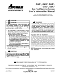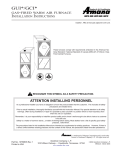
1
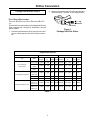
LPTK09
Heating & Air Conditioning
®
Propane Gas Conversion Kit
Com fort. Q uality. Trust.
Installation Instructions
DE SIG N
CE
R TI FI E D
C E RT I F I E D
Description
This kit converts Amana gas-fired units from natural to propane gas. The conversion from natural gas (as shipped
from the factory) to propane gas requires:
- Replacing burner orifices
- Replacing pilot orifice (Package Gas-Electric Units only)
- Replacing gas valve regulator spring (all single stage units)
- Removing NOx screens/turbulators (screens/turbulators not used on all units)
- Applying conversion identification labels
Any conversion to propane gas is the responsibility of, and at the risk of, the person making the conversion. This kit
applies only to the following:
Product
Models
Non-Condensing Gas Furnaces
GUIA, GUIB, GUIC, GUID, GCIA,
GCIB, GCIC, GUIS, GCIS, GUIV
Condensing Gas Furnaces
GUC, GUD, GUX, GCD, GDC,
GUCA, GCCA, GUVA
Package Gas-Electric Units
PGA**C, PGB**C, PGD**C
This kit includes:
Installation Instructions
Propane gas burner orifice (#55)
Propane gas pilot orifice (BBR12 for Package
Gas-Electric units equipped with pilot Honeywell
system)
Gas Valve Conversion kits (with instructions)
Conversion rating plate
Conversion date certificate
Screen/Turbulator removal warning tag
Wire ties
RECOGNIZE THIS SYMBOL AS A SAFETY PRECAUTION.
ATTENTION INSTALLING PERSONNEL
As a professional installer you have an obligation
to know the product better than the customer.
This includes all safety precautions and related
items.
Prior to actual installation, thoroughly familiarize
yourself with this Instruction Manual. Pay special
attention to all safety warnings. Often during
installation or repair it is possible to place
yourself in a position which is more hazardous
than when the unit is in operation.
June 2001 (1)
Rev. 3
Remember, it is your responsibility to install the
product safely and to know it well enough to be
able to instruct a customer in its safe use.
Safety is a matter of common sense...a matter of
thinking before acting. Most dealers have a list of
specific good safety practices...follow them.
The precautions listed in this Installation Manual
are intended as supplemental to existing
practices. However, if there is a direct conflict
between existing practices and the content of
this manual, the precautions listed here take
precedence.
Amana
1810 Wilson Parkway • Fayetteville, TN 37334
10308713
Contents
General Information ....................................................................................................................... 3
Orifice Conversion ......................................................................................................................... 4
Non-Condensing Furnaces ..................................................................................................................... 4
Manifold/Valve Removal .................................................................................................................................... 4
Burner Orifice Replacement ............................................................................................................................. 4
Condensing Furnaces ............................................................................................................................. 4
Manifold/Valve Removal .................................................................................................................................... 4
GUD/GCD Furnaces........................................................................................................................ 4
All Other Condensing Furnaces ....................................................................................................... 4
Burner Orifice Replacement ............................................................................................................................. 4
Package Gas-Electric ............................................................................................................................. 4
Manifold/Valve Removal .................................................................................................................................... 4
Package Gas-Electric Units With Pilot ............................................................................................ 4
Package Gas-Electric Units Without Pilot ....................................................................................... 4
Burner Orifice Replacement ............................................................................................................................. 4
All Package Gas-Electric Units ....................................................................................................... 4
Pilot Orifice Replacement ................................................................................................................................. 5
Package Gas-Electric Units Equipped With Pilot ............................................................................ 5
Gas Valve Regulator Spring Replacement ................................................................................... 6
Single Stage Units Only .................................................................................................................................... 6
NOx Screen Removal ..................................................................................................................... 7
Non-Condensing Furnaces and Package Gas-Electric .................................................................................. 7
Manifold Reinstallation ................................................................................................................. 8
Condensing & Non-Condensing Furnaces ............................................................................................. 8
Package Gas-Electric ............................................................................................................................. 8
Package Gas-Electric Units Equipped With Pilot ............................................................................ 8
Package Gas-Electric Units Without Pilot ....................................................................................... 8
Adjustments, Checks, and Tests ................................................................................................... 9
Orifice and Igniter Check ........................................................................................................................ 9
Line Pressure Check ............................................................................................................................... 9
All Units .............................................................................................................................................................. 9
Manifold Pressure Check ........................................................................................................................ 9
Single Stage Units (GUIA/B/C/D, GCIA/B/C, GCD, GDC GUC/D/X, GCC, GUCA, GCCA, PGA/B/D**C) ........ 9
Two-Stage Units (GUIS/V, GCIS, GUVA) ........................................................................................................... 9
Unit Operation Check and Labelling ..................................................................................................... 10
Verify Gas Input Rate(s) .................................................................................................................................. 10
Check Normal Operating Sequence of Ignition System ............................................................................... 10
Inspect Burner Flame ...................................................................................................................................... 10
Check and Adjust Unit Temperature rise ....................................................................................................... 10
Label Attachment ............................................................................................................................................ 10
Setting GUD/GCD Manifold Pressure ......................................................................................... 12
2
General Information
WARNING
PERSONAL INJURY HAZARD
This conversion kit must be installed by a qualified agency in accordance with the
manufacturer’s instructions and all applicable codes and requirements of the authority
having jurisdiction. If the information in these instructions is not followed exactly, a fire,
explosion or production of carbon monoxide can result causing property damage, personal
injury or loss of life. The qualified service agency performing this work assumes responsibility for the proper conversion of this appliance with this kit.
WARNING
PERSONAL INJURY HAZARD
To prevent death, personal injury, or property damage due to fire or explosion from a
propane gas leak, install a gas detecting warning device. A gas detecting warning device
is the only reliable way to detect a propane gas leak. Do not rely on smell as rust can reduce
the level of odorant in propane gas.
Remember:
• Propane gas is heavier than air and leaking gas can settle in any low area or confined
space.
• A propane gas odor can fade, making the gas undetectable.
• A warning device is a required item, if the propane gas unit is installed in either a
basement, an excavated area or a confined space.
If the presence of gas is suspected:
• Do not try to light any appliance.
• Do not touch any electrical switch or use any phone in your building.
• Immediately call your gas supplier from a neighbor’s phone. Follow the gas supplier’s
instructions.
• If you cannot reach your gas supplier, call the fire department.
Contact a local propane gas supplier about installing a gas detecting warning device.
IN CANADA “THE CONVERSION SHALL BE CARRIED OUT IN ACCORDANCE WITH THE REQUIREMENTS OF
THE PROVINCIAL AUTHORITIES HAVING JURISDICTION AND IN ACCORDANCE WITH THE REQUIREMENTS
OF THE CAN/CSA B149.1 AND B149.2 INSTALLATION CODE.”
Due to policy of continual product improvement, the right is reserved to
change specifications and design without notice.
3
Orifice Conversion
The gas manifold along with the gas valve must be removed
in order to access the burner orifices. Before proceeding,
shut off gas supply at manual shutoff and turn off
power to unit.
5. Remove the screws securing the manifold and valve
to the burner bracket. Separate gas manifold and
valve from burner bracket.
ALL OTHER CONDENSING FURNACES
1. Disconnect wiring from the gas valve.
2. Where necessary, cut wire ties securing wiring to
manifold.
CAUTION
3. Remove the screws securing the manifold and valve
to the burner bracket . Separate gas manifold and
valve from burner bracket .
PERSONAL INJURY HAZARD
The gas supply must be shut off prior to
disconnecting the electrical power, before
proceeding with the conversion.
BURNER ORIFICE REPLACEMENT
1. Remove natural gas orifices from gas manifold using
a box end wrench.
2. Install propane gas orifices. Tighten orifices with a
box-end wrench; do not use a socket wrench as it
could damage the orifices; do not cross-thread or
overtighten. Refer to table 1 for the appropriate LP
kit and orifice size.
Non-Condensing Furnaces
MANIFOLD/VALVE REMOVAL
Package Gas-Electric
1. Disconnect wiring from the gas valve.
2. Remove burner box door.
MANIFOLD/VALVE REMOVAL
PACKAGE GAS-ELECTRIC UNITS WITH PILOT
NOTE: GUID furnaces do not have a burner box
door.
1. Disconnect wiring from the gas valve.
3. Where necessary, cut wire ties securing wiring to
manifold.
2. Where necessary, cut wire ties securing wiring to
manifold.
4. Remove the screws securing the manifold and valve
to the burner box bracket. Separate gas manifold
and valve from burner box.
3. Remove the screws securing the pilot assembly to
the burner tray.
4. Remove the pilot assembly, pilot tubing, gas manifold
and valve together. CAUTION: Pilot tube is delicate
do not bend or crimp.
BURNER ORIFICE REPLACEMENT
1. Remove natural gas orifices from gas manifold using
a box end wrench.
PACKAGE GAS-ELECTRIC UNITS WITHOUT PILOT
2. Install propane gas orifices. Tighten orifices with a
box-end wrench; do not use a socket wrench as it
could damage the orifices; do not cross-thread or
overtighten. Refer to Table 1 for the appropriate LP
kit and orifice size.
1. Disconnect wiring from the gas valve.
2. Where necessary, cut wire ties securing wiring to
manifold.
3. Remove the screws securing the manifold and valve
to the burner box or burner bracket. Separate gas
manifold and valve from burner box or burner
bracket.
Condensing Furnaces
BURNER ORIFICE REPLACEMENT
ALL PACKAGE GAS-ELECTRIC UNITS
MANIFOLD/VALVE REMOVAL
GUD/GCD FURNACES
1. Remove natural gas orifices from gas manifold using
a box end wrench.
1. Disconnect wiring from the gas valve.
2. Install propane gas orifices. Tighten orifices with a
box-end wrench; do not use a socket wrench as it
could damage the orifices; do not cross-thread or
overtighten. Refer to table 1 for the appropriate LP
kit and orifice size.
2. Remove burner box door.
3. Disconnect burner box hose from gas valve.
4. Where necessary, cut wire ties securing wiring to
manifold.
4
Orifice Conversion
2. Replace with propane gas pilot orifice provided and
reconnect wiring. Use care, do not damage igniter.
Package Gas-Electric Cont’d
PILOT ORIFICE REPLACEMENT
PACKAGE GAS-ELECTRIC UNITS EQUIPPED WITH PILOT
The pilot orifice must be replaced on Packaged Gas-Electric
Units equipped with a Honeywell “Smartvalve” and pilot
ignition system.
Pilot Orifice
Figure 1
Package Unit Pilot Orifice
1. Disconnect pilot assembly wiring from gas valve and
remove natural gas pilot orifice from the pilot assembly.
Propane Gas Orifices
Product
Type
Non-Condensing
Gas Furnaces
Condensing Gas Furnaces
Package Gas-Electric Units
Standard Altitude
Model
Kit
Number
Altitude
(ft)
GUIA,GUIB,
GCIA, GCIB
LPTK09
0 - 7500
#55
GUIC, GCIC,
GUID
LPTK09
0 - 6000
GUIS, GCIS,
GUIV
LPTK09
GUC, GUD,
GUX, GDC,
GCD, GCC
High Altitude
Burner Pilot
Orifice Orifice
Kit
Number
Altitude
(ft)
Burner
Orifice
Pilot
Orifice
N/A
HALP09
7501 - 11000
#56
N/A
#55
N/A
HALP09
6001 - 11000
#56
N/A
0 - 7000
#55
N/A
HALP09
7001 - 8500
#56
N/A
LPTK09
0 - 4500
#55
N/A
HALP09
4501 - 9500
#56
N/A
GUCA, GCCA
LPTK09
0 - 7000
#55
N/A
HALP10
7001 - 11000
#56
N/A
N/A
HALP11
7001 - 11000
#56
N/A
BBR12 HALP09
6001 - 9500
#56
BBR12
6001 - 9500
#56
N/A
GUVA
LPTK09
0 - 7000
#55
PGA**C***D
PGB**C***D
PGD**C***D
LPTK09
0 - 6000
#55
PGA**C***E
PGB**C***E
PGD**C***E
LPTK09
0 - 6000
#55
Table 1
5
N/A
HALP09
Gas Valve Regulator Spring Replacement
SINGLE STAGE UNITS ONLY
The gas valve regulator spring must be replaced on all single stage gas furnaces and packaged gas/electric units.
Replace the gas valve regulator spring with the propane gas regulator spring from the proper spring kit. Follow the
manufacturer’s instructions provided in the spring kit. Discard all unused spring kits. Two-stage units do not
require a spring change.
CAUTION
Spring kits are not interchangeable. A White-Rodgers gas valve requires a White-Rodgers
spring kit; a Honeywell gas valve requires a Honeywell spring kit, etc. Refer to Figures 2
through 8 for gas valve identification.
Mates With
Honeywell
Q3450* Pilot
Harness
ON
OFF
OFF
Inlet Pressure Tap
Gas Control/Valve
Knob
Gas Valve
On/Off
Control Knob
Figure 2
Honeywell
Model VR-8205
OUTLET
INLET
Pilot Tube
Connection
Outlet Pressure Tap
IN
IN
INLET
ON
OUTLET
ON
IGNITOR
PSI
INLET
2
1 /2PS I
Inlet Pressure
Tap
OFF
Outlet (Manifold)
Pressure Tap
Honeywell
Pressure Regulator
Adjustment (Under
Cap Screws)
OUTLET
CONTROL
Pressure Regulator
Adjustment
(Under Cap Screw)
Mates With
HONEYWELL
Q3450* Pilot
Harness
Pressure Regulator
Adjustment (Under
Cap Screw)
Pilot Tube
Connection
Mates With
Socket Housing
Control Module
Outlet Pressure Tap
1/8 N.P.T., Plugged
(Steel)
Figure 4
Honeywell
Model SV9501
Figure 3
Honeywell
Model SV9500
High Manifold
Regulator Adjustment
Screw (Under Cap)
Gas Valve
On/Off
Control Knob
Gas Valve
On/Off
Selector
Switch
PM
C
HI
INLET
OUTLET
Inlet
Outlet
O
F
F
INLET
M
1
P
3
C
2
ON
OUTLET
OFF
ON
Inlet Pressure Tap
(Side of Valve)
Pressure Regulator
Adjustment
(Under Cap Screw)
Outlet (Manifold)
Pressure Tap
Inlet Pressure Tap
Outlet (Manifold)
Low Manifold
(Side of Valve)
Pressure Tap
Regulator Adjustment
Gas Valve
(Side of Valve)
Screw (Under Cap)
Control Knob
Figure 5
White-Rodgers
Model 36E36 or 36E37
Gas Valve
On/Off
Control Lever
In ON Position
Figure 6
White-Rodgers
Model 36E96 or 36E54
Outlet (Manifold)
Pressure Tap
(Side of Valve)
Inlet Pressure Tap
(Side of Valve)
Gas Valve
On/Off
Selector
Switch
OUTLET
OUTLET
Inlet Pressure Tap
(Side of Valve)
Inlet Pressure Tap
(Side of Valve) Pressure Regulator
Adjustment
(Under Cap Screw)
Pressure Regulator
Adjustment
(Under Cap Screw)
Outlet (Manifold)
Pressure Tap
Figure 9
White-Rodgers
Model 36F22
Figure 8
Robertshaw
Model 7222
6
Outlet (Manifold)
Pressure Tap
(Side of Valve)
Figure 7
White-Rodgers
Model 36E22 or 36E23
INLET
INLET
Pressure Regulator
Adjustment
(Under Cap Screw)
NOx Screen Removal
WARNING
PERSONAL INJURY HAZARD
All metal screens must be removed from the heat exchanger tubes when using propane gas.
Failure to comply could cause serious personal injury or death. Failure to comply with this
requirement will also void warranty coverage.
NOTE: To prevent premature heat exchanger failure, follow the instructions below to remove all metal screen inserts
from the entrance of heat exchanger tubes during propane conversions. Not all models will have metal screen inserts.
NON-CONDENSING FURNACES AND PACKAGE GAS-ELECTRIC
PARTITION PANEL
1. Remove the screws securing the burner box to the
partition panel. Separate burner box from unit
RETENTION PLATE
2. Remove the screw(s) securing the NOx screen retention plate and remove the plate.
3. Remove and discard NOx screens.
4. Reinstall the NOx screen retention plate and burner
box.
BURNER BOX ASSY.
SCREENS
Figure 10
Typical NOx Screen Removal
7
Manifold Reinstallation
Condensing & Non-Condensing Furnaces
CAUTION
1. Reinstall gas manifold and valve.
Pilot assembly must be properly aligned
with burners for proper ignition. Refer to
Figure 11.
2. Reconnect wiring (and burner box hose on GUD and
GCD furnaces) to gas valve. Secure wiring to manifold using wire ties provided. Ensure wiring does not
interfere with orifices or burners.
Package Gas-Electric
PACKAGE GAS-ELECTRIC UNITS EQUIPPED WITH PILOT
CORRECT
POSITION
1. Reinstall gas manifold and valve.
2. Secure the pilot assembly to the burner tray.
3. Reconnect wiring to gas valve. Secure wiring to
manifold using wire ties provided. Ensure wiring
does not interfere with orifices or burners.
PACKAGE GAS-ELECTRIC UNITS WITHOUT PILOT
1. Reinstall gas manifold and valve.
2. Reconnect wiring to gas valve. Secure wiring to
manifold using wire ties provided. Ensure wiring
does not interfere with orifices or burners.
"A"
DIMENSION
"A" CANNOT
EXCEED 1/4"
Figure 11
Pilot Assembly Positioning
8
Adjustments, Checks, and Tests
The following adjustments and checks are a required part of this conversion. Adjustments and checks include:
•
Leak checking orifices
•
Verifying proper igniter positioning
•
Checking line and adjusting manifold gas pressures
•
Verifying proper unit operation (input rate, operational sequence, burner flame, temperature rise, etc.)
Manifold Pressure Check
Orifice and Igniter Check
SINGLE STAGE UNITS
(GUIA/B/C/D, GCIA/B/C, GCD, GDC GUC/D/X,
GCC, GUCA, GCCA, PGA/B/D**C)
ADJUST GAS MANIFOLD PRESSURE
WARNING
PERSONAL INJURY HAZARD
Set the manifold pressure. The pressure must be
between 9.7 and 10.3 inches W.C. For setting direct
vent (GUD, GCD) furnace manifold pressure, see
“Setting GUD and GCD Manifold Pressure” section at the
end of this manual.
To prevent death, personal injury or
property damage due to fire or explosion,
do not use a flame to check for leaks.
1. Turn OFF gas to the unit at the manual gas shutoff
valve.
1. Leak check burner orifice threads using a soap solution.
2. Connect a calibrated water manometer or appropriate
gas pressure gauge at the gas valve outlet pressure
tap.
2. Visually inspect the igniter for damage. Replace if
damaged.
Package Gas Electric Units
3. Turn ON gas supply and operate unit.
Verify that the pilot assembly is in the proper place.
4. Remove the cover over the manifold pressure regulator adjustment screw.
3. Reinstall the burner box door (where applicable).
5. Adjust manifold pressure: Turn adjustment screw out
(counterclockwise) to decrease pressure. Turn in
(clockwise) to increase pressure.
Line Pressure Check
ALL UNITS
CHECK LINE PRESSURE SUPPLIED
TO
TWO-STAGE UNITS
(GUIS/V, GCIS, GUVA)
ADJUST GAS MANIFOLD PRESSURE
GAS VALVE
1. Turn OFF the power and gas at the manual gas
shutoff valve.
1. Turn OFF gas to the unit at the manual gas shutoff
valve.
2. Connect a calibrated water manometer or appropriate
gas pressure gauge to the “inlet pressure tap” of the
gas valve or “gas piping drip leg”.
2. Connect a calibrated water manometer or appropriate
gas pressure gauge at the gas valve outlet pressure
tap.
3. Turn ON the power and gas, put the unit into heating
cycle and turn on all other gas consuming appliances.
3. Turn ON gas supply and operate unit.
4. Remove the cap screw from the low stage manifold
pressure regulator.
4. Measure the gas supply pressure with the burners firing. The inlet gas pressure must be between 11.0
and 13.0 inches W.C. If supply pressure differs from
required, make necessary adjustments to pressure
regulator(s), gas piping, etc.
5. Using an Allen wrench, increase low stage manifold
pressure by adjusting the low stage manifold regulator so the furnace will light and carry over.
6. Remove the cap screw from the high stage manifold
pressure regulator adjustment location.
5. Turn OFF gas to the unit at the manual shutoff valve
and disconnect manometer. Turn OFF any unnecessary appliances started in step 3.
7. Using an Allen wrench, adjust high stage manifold
regulator to the required manifold pressure (Table 2).
8. Reinstall the high stage manifold regulator cap screw.
Confirm high stage manifold pressure.
9
Adjustments, Checks, and Tests
Manifold Pressure Adjustment Cont’d
Unit Operation Check and Labelling
VERIFY GAS INPUT RATE(S)
9. Using an Allen wrench, adjust low stage manifold
regulator to the required pressure (Table 2).
Ensure that the appropriate orifices have been installed and the manifold pressure has been set as
stated in these instructions.
10. Reinstall the low stage manifold regulator cap screw.
Confirm low stage manifold pressure.
11. Turn OFF gas supply to unit, and disconnect manometer.
CHECK NORMAL OPERATING SEQUENCE
SYSTEM
Manifold Pressure for Propane Gas
Two-Stage Units
Low Stage
High Stage
OF IGNITION
Check the normal operating sequence of the ignition
system to ensure burners light properly.
5.7 to 6.3" W.C.
INSPECT BURNER FLAME
The burner flames should be stable, soft and blue
(dust may cause orange tips but they must not be yellow). They should extend directly outward from the
burners without curling, floating, or lifting off.
9.7 to 10.3" W.C.
Table 2
CHECK AND ADJUST UNIT TEMPERATURE RISE
Check and adjust unit temperature rise(s) as described in the installation manual.
Temperature rise must be within the range shown on
the furnace rating plate.
LABEL ATTACHMENT
Attach the label (found in the spring kit), indicating
propane gas conversion, to the gas valve.
Attach conversion data plate, with correct input rating,
adjacent to the unit rating plate. Use Tables 3 or 4 to
determine the correct data plate to be applied.
Post “conversion date certificate” adjacent to the unit
rating plate.
10
Adjustments, Checks, and Tests
Single Stage Units
Input Ratings (Standard Altitude)
Size
Model
Two Stage Units
Input Ratings (Standard Altitude)
Propane Input
(BTU/hr)
Size
GUIA, GUIB, GUIC,
GCIA, GCIB, GCIC,
GUID,
045
GCD, GDC,
GUCA, GCCA,
41,400
PGB**C, PGD**C
GUC, GUD, GUX, GCC
40,500
GCD, GDC,
GUCA, GCCA,
62,100
PGA**C, PGB**C,
PGD**C
GUC, GUD, GUX, GCC
63,000
GUIA, GUIB, GUIC,
GCIA, GCIB, GCIC,
GUID,
090
GCD, GDC,
GUCA, GCCA,
82,800
PGA**C, PGB**C,
PGD**C
GUC, GUD, GUX, GCC
81,000
GUIA, GUIB, GUIC,
GCIA, GCIB, GCIC,
GUID,
115
GCD, GDC,
GUC, GUD, GUX, GCC,
GUCA, GCCA,
103,500
PGA**C, PGB**C,
PGD**C
140
GUIA, GUIB, GUIC,
GCIA, GCIB, GCIC,
High Stage Input
(BTU/hr)
Low Stage Input
(BTU/hr)
045
GUVA
41,400
32,000
070
GUIS,GCIS, GUIV,
GUVA
62,100
48,000
090
GUIS, GCIS, GUIV,
GUVA
82,800
64,000
115
GUIS, GUIV,GUVA
103,500
80,000
140
GUIS, GUIV
124,200
96,000
Table 4
GUIA, GUIB, GUIC,
GCIA, GCIB, GCIC,
GUID,
070
Model
124,200
PGB**C, PGD**C
Table 3
11
Setting GUD/GCD Manifold Pressure
Only small variations in gas flow should be made when adjusting the gas valve pressure regulator. For propane gas,
the manifold pressure must 9.7 to 10.3” W.C.
WARNING
To prevent death or personal injury due to carbon monoxide, all hoses must be connected
as shown in Figure 12. Failure to connect the hose between the pressure switch and the
burner box could result in excessive generation of carbon monoxide.
GAS VALVE
A
C
BURNER
BOX
B
TO
BURNER
BOX
TO
VENT
BLOWER
TO
VENT
BLOWER
TO
BURNER
BOX
TRIDELTA
TRIDELTA
PRESSURE
SWITCH
(METAL & PLASTIC BODY)
(ROTATED 90 FOR CLARITY)
(ALL METAL BODY)
D
VENT
BLOWER
TO
VENT
BLOWER
TO
BURNER
BOX
U-TUBE MANOMETER
A - CAP OVER ADJUSTMENT SCREW MUST
BE IN PLACE WHEN FURNACE IS
OPERATING.
B - SEE PRESSURE SWITCH DIAGRAM
FOR PRESSURE SWITCH HOSE
CONNECTIONS.
MPL
PRESSURE SWITCH DIAGRAM
TO MEASURE MANIFOLD PRESSURE CONNECT MANOMETER BETWEEN C AND D.
C - HOSE BETWEEN GAS VALVE AND AIR
BOX (TEE TO BE SUPPLIED BY
SERVICER.)
D - TAPPED OPENING IN MANIFOLD (HOSE
BARB TO BE SUPPLIED BY SERVICER.)
10291404
Figure 12
GUD, GCD Manifold Pressure Measurement
1. Turn OFF gas to the unit at the manual gas shutoff valve.
2. Connect a calibrate “U” tube manometer (or appropriate gas pressure gauge) between the tapped outlet in the gas
manifold and a tee (field-supplied) in the hose from the burner box to the gas valve.
3. Turn ON gas supply and operate unit. NOTE: Burner box cover must be in place.
4. Remove the cover over the manifold pressure regulator screw.
5. Adjust manifold pressure. Turn adjustment screw out (counterclockwise) to decrease pressure. Turn adjustment
screw in (clockwise) to increase pressure.
6. Reinstall the cover over the manifold pressure regulator adjustment screw in order to check manifold pressure.
Make further adjustments if necessary.
7. Turn OFF gas supply to unit and disconnect manometer.
8. Go to “Unit Operation Check and Labelling” section.
12