1
Summit® WM Technical Reference Guide
Software Version 5.3
Extreme Networks, Inc.
3585 Monroe Street
Santa Clara, California 95051
(888) 257-3000
(408) 579-2800
http://www.extremenetworks.com
Published: December 2008
Part number: 120483-00 Rev 01
AccessAdapt, Alpine, Altitude, BlackDiamond, EPICenter, Essentials, Ethernet Everywhere, Extreme Enabled,
Extreme Ethernet Everywhere, Extreme Networks, Extreme Standby Router Protocol, Extreme Turbodrive, Extreme
Velocity, ExtremeWare, ExtremeWorks, ExtremeXOS, Go Purple Extreme Solution, ScreenPlay, Sentriant,
ServiceWatch, Summit, SummitStack, Triumph, Unified Access Architecture, Unified Access RF Manager, UniStack,
the Extreme Networks logo, the Alpine logo, the BlackDiamond logo, the Extreme Turbodrive logo, the Summit
logos, and the Powered by ExtremeXOS logo are trademarks or registered trademarks of Extreme Networks, Inc. or
its subsidiaries in the United States and/or other countries.
sFlow is a registered trademark of InMon Corporation.
Specifications are subject to change without notice.
All other registered trademarks, trademarks, and service marks are property of their respective owners.
© 2007-2008 Extreme Networks, Inc. All Rights Reserved.
2
Summit WM Technical Reference Guide, Software Version 5.3
Table of Contents
About this guide .............................................................................................................................. 9
Who should use this guide ...........................................................................................................9
What is in this guide ...................................................................................................................9
Formatting conventions..............................................................................................................10
Documentation feedback ...........................................................................................................10
Protocols and standards.............................................................................................................11
Chapter 1: System Capacities ........................................................................................................ 13
Summit WM Controller WM20/WM200/2000...............................................................................13
Summit WM Controller WM100/WM1000....................................................................................13
Altitude Access Point ................................................................................................................14
Feature capacities .....................................................................................................................15
Mobility..............................................................................................................................15
Availability .........................................................................................................................15
Maximum failover capacity matrix .........................................................................................16
Chapter 2: Configuration of Dynamic Host Configuration Protocol (DHCP) ......................................... 17
Service Location Protocol (SLP) (RFC2608).................................................................................18
DHCP Options for Service Location Protocol (RFC2610) ...............................................................18
SLP Directory Agent Option (Option 78) ......................................................................................18
SLP Service Scope Option (Option 79) ........................................................................................19
Dynamic Host Configuration Protocol – Summit WM Controller and AP Discovery and other Services.20
DHCP setup using the internal DHCP server.................................................................................22
Using the Summit WM Controller as the default DHCP server ........................................................23
DHCP setups for relayed WM-AD’s and AP deployment networks....................................................23
DHCP configuration example: OSC dhcpd on Linux ......................................................................24
General options.........................................................................................................................26
Altitude Access Point Discovery mechanism.................................................................................26
Wireless AP DHCP Registration Setup (WINDOWS).................................................................27
Create a New DHCP Scope and Configure Option 78 ..............................................................27
DNS Settings for Altitude AP Discovery .................................................................................29
Static Altitude AP Addressing...............................................................................................29
Chapter 3: Rogue Access Point Detection ....................................................................................... 31
Chapter 4: Creating the Windows Security Infrastructure ................................................................. 33
Intranet Wireless Deployment Steps ............................................................................................34
Step 1: Configuring the Certificate Infrastructure .........................................................................35
Step 1a: Installing a Certificate Infrastructure........................................................................36
Step 1b: Installing Computer Certificates ..............................................................................38
Step 1c: Installing User Certificates......................................................................................38
Step 2: Configuring Active Directory for Accounts and Groups .......................................................40
Summit WM Technical Reference Guide, Software Version 5.3
3
Table of Contents
Step 3: Configuring the Primary IAS Server..................................................................................40
Step 3a: Configuring IAS .....................................................................................................40
Step 3b: Configuring a Wireless Remote Access Policy ...........................................................43
Step 4: Configuring the secondary IAS server (if applicable) ..........................................................48
Step 5: Deploying and Configuring Wireless APs ..........................................................................49
Step 6: Configuring Wireless Network (IEEE 802.11) Policies Group Policy Settings .......................49
Step 7: Installing Computer Certificates on Wireless Client Computers for EAP-TLS.........................50
Step 8: Installing User Certificates on Wireless Client Computers for EAP-TLS................................51
Submit a user certificate request via the Web ........................................................................51
Request a certificate ...........................................................................................................51
Floppy Disk-Based Installation..............................................................................................52
Export a certificate ..............................................................................................................52
Import a certificate..............................................................................................................52
Step 9: Configuring Wireless Clients for EAP-TLS.........................................................................53
Step 10: Configuring Wireless Client Computers for PEAP-MS-CHAP v2 .........................................54
Additional Intranet Wireless Deployment Configurations................................................................56
Internet Access for Business Partners....................................................................................56
Using Guest Access .............................................................................................................56
Using Validated Access........................................................................................................56
Using a Third-Party CA ........................................................................................................57
Certificates on Wireless Client Computers ..............................................................................58
Configuring Proxy Server Settings ........................................................................................58
Chapter 5: Windows Recommendations and Best Practices ............................................................. 61
Security ...................................................................................................................................61
PKI..........................................................................................................................................61
Altitude APs .............................................................................................................................62
Wireless Network Adapters .........................................................................................................62
Active Directory ........................................................................................................................63
RADIUS ...................................................................................................................................63
Scalability ................................................................................................................................64
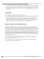
Using Computer-only Authentication ...........................................................................................64
Configuring Computer-only Authentication using the Wireless Network (IEEE 802.11) Policies Group
Policy Extension..................................................................................................................65
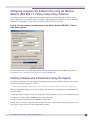
Enabling Computer-only Authentication Using the Registry......................................................65
Summary..................................................................................................................................66
Chapter 6: Summit WM Controller diagnostics ................................................................................ 67
Summit WM Controller WM200/2000 diagnostics ........................................................................67
Summit WM Controller WM200/2000 capacity ......................................................................67
Summit WM Controller WM200/2000 license capacity ...........................................................67
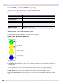
Summit WM Controller WM200/2000 LEDs...........................................................................68
System Startup ...................................................................................................................71
Summit WM Controller WM200/2000 application states .........................................................71
Summit WM Controller WM200/2000 protocols .....................................................................74
Summit WM Controller WM20 diagnostics ...................................................................................76
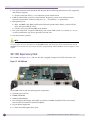
Summit WM Controller WM20 capacity .................................................................................76
Using the console port .........................................................................................................76
Summit WM Controller WM20 rescue procedure.....................................................................77
4
Summit WM Technical Reference Guide, Software Version 5.3
Table of Contents
Summit WM Controller WM20 capacity .................................................................................78
Summit WM Controller WM20 LEDs......................................................................................78
Summit WM Controller WM20 protocols ................................................................................79
Chapter 7: Hardware maintenance ................................................................................................. 81
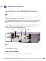
Summit WM Controller WM200/2000 maintenance......................................................................81
Summit WM Controller WM200/2000 power supply ...............................................................82
Power FRUs........................................................................................................................83
Fan Tray.............................................................................................................................83
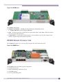
MF1000 Media Flash Card...................................................................................................84
NP4000 Network Processor Card..........................................................................................85
SC1100 Supervisory Card ....................................................................................................86
Summit WM Controller WM200/2000 power and maintenance procedures ...............................87
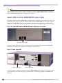
Summit WM Controller WM20 maintenance.................................................................................91
Summit WM Controller WM20 power and maintenance procedures ..........................................93
Chapter 8: Altitude AP antenna selection........................................................................................ 95
Chapter 9: AP as 802.1X supplicant............................................................................................... 97
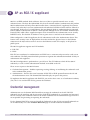
Credential management .............................................................................................................97
Transferring credentials from the Summit WM Controller to AP................................................98
Storing credentials on the AP ...............................................................................................99
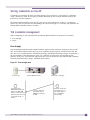
TLS credential management .................................................................................................99
TLS certificate expiration ...................................................................................................100
TLS server authentication ..................................................................................................101
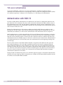
Authentication with 802.1X .....................................................................................................101
EAP-TLS authentication.....................................................................................................102
EAP-PEAP authentication ..................................................................................................103
Configuring APs for .1X authentication ......................................................................................103
General configuration ........................................................................................................103
EAP-PEAP configuration ....................................................................................................103
EAP-TLS configuration with the Summit WM Controller as proxy............................................104
EAP-TLS configuration with the Summit WM Controller as pass-through .................................105
Bulk EAP-TLS configuration ...............................................................................................105
Bulk EAP-PEAP configuration.............................................................................................106
Verifying the AP .1X configuration ............................................................................................106
Limits and technical data ........................................................................................................107
Chapter 10: MAC-Based Authentication ........................................................................................ 109
How MAC-based authentication works .......................................................................................109
Roaming ................................................................................................................................110
Radius redundancy..................................................................................................................110
Rejection and failure ...............................................................................................................110
Additional RADIUS attributes ...................................................................................................110
Assumptions/recommendations.................................................................................................111
Use Cases ..............................................................................................................................111
Vendor Interoperability ............................................................................................................111
Chapter 11: FreeRADIUS and Security .......................................................................................... 113
Overview ................................................................................................................................113
Summit WM Technical Reference Guide, Software Version 5.3
5
Table of Contents
Configuration ..........................................................................................................................113
radiusd.conf file................................................................................................................113
users file ..........................................................................................................................114
eap.conf file .....................................................................................................................115
Debugging FreeRADIUS...........................................................................................................116
Chapter 12: RADIUS Attributes ..................................................................................................... 117
RADIUS Vendor-Specific Attributes (VSAs) ................................................................................117
RADIUS accounting ................................................................................................................118
Account-Start packet .........................................................................................................118
Account-Stop/Interim packet ..............................................................................................118
Termination codes.............................................................................................................119
Supported attributes in RADIUS authentication and RADIUS response messages ..........................120
RADIUS-based login authentication ..........................................................................................121
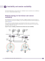
Chapter 13: Availability and session availability ........................................................................... 123
Network topology for fast failover and session availability ............................................................123
Fast failover and session availability deployment scenarios..........................................................124
When to use fast failover..........................................................................................................124
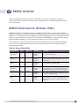
Chapter 14: SNMP MIBs .............................................................................................................. 125
IF-MIB ...................................................................................................................................125
RFC1213 ...............................................................................................................................126
IEEE802dot11-MIB ................................................................................................................126
Proprietary MIBs .....................................................................................................................127
EXTREME-SUMMIT-WM-MIB.my........................................................................................127
EXTREME-SUMMIT-WM-DOT11-EXTS-MIB .........................................................................127
EXTREME-SUMMIT-PRODUCT-MIB....................................................................................127
EXTREME-SUMMIT-WM-BRANCH-OFFICE-MIB...................................................................127
Chapter 15: DRM – Dynamic Radio Management ........................................................................... 129
Automatic Channel Selection (ACS) overview .............................................................................129
Automatic Transmit Power Control (ATPC) overview ....................................................................130
Dynamic Channel Selection (DCS) overview ...............................................................................130
Chapter 16: Call Admission Controls, TSPEC, and QoS................................................................... 131
Chapter 17: Portable and text editable backup.............................................................................. 133
Working with supported files ....................................................................................................133
.cli file .............................................................................................................................133
Migration of the text editable backup files .................................................................................134
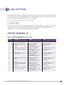
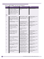
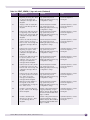
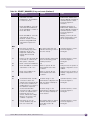
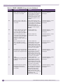
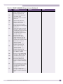
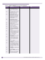
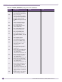
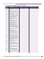
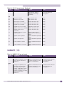
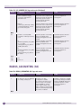
Chapter 18: Logs and Events........................................................................................................ 135
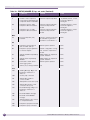
STARTUP_MANAGER (0) ........................................................................................................135
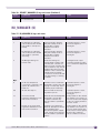
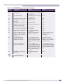
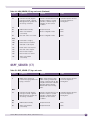
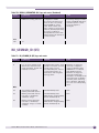
EVENT_SERVER (1) ................................................................................................................137
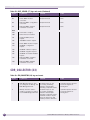
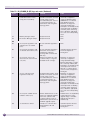
CONFIG_MANAGER (2) ...........................................................................................................143
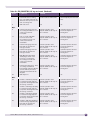
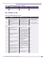
STATS_SERVER (3) ................................................................................................................145
SECURITY_MANAGER (4) .......................................................................................................147
6
Summit WM Technical Reference Guide, Software Version 5.3
Table of Contents
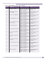
RU_MANAGER (6) ..................................................................................................................159
RADIUS_CLIENT (7) ...............................................................................................................162
HOST_SERVICE_MANAGER (8)................................................................................................165
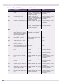
VNMGR (9) ............................................................................................................................165
STACK_ADAPTER (10) ............................................................................................................172
CLI (11) .................................................................................................................................172
LANGLEY (13)........................................................................................................................173
NSM_SERVER (15) .................................................................................................................174
OSPF_SERVER (17) ................................................................................................................175
CDR_COLLECTOR (23)............................................................................................................176
RF_DATA_COLLECTOR (36) ....................................................................................................181
REMOTE_INS (58)..................................................................................................................182
LLC_HANDLER (62)................................................................................................................187
RADIUS_ACCOUNTING (64) ....................................................................................................188
RU_SESMGR_ID (65)..............................................................................................................189
MU_SESMGR_ID (66) .............................................................................................................191
FILTER_MGR_ID (67) .............................................................................................................192
REDIRECTOR4 (68) ................................................................................................................195
BEAST (75)............................................................................................................................195
BEACONPOINT (99)................................................................................................................197
FILTER_MANAGER_ID (103) ...................................................................................................197
REDIR_ID (106) .....................................................................................................................198
CPDP_AGENT_ID (110)...........................................................................................................198
PORT_INFO_J_MANAGER (118) ..............................................................................................198
ECHELON (126) .....................................................................................................................199
Chapter 19: Reference lists of standards ...................................................................................... 201
RFC list..................................................................................................................................201
802.11 standards list..............................................................................................................202
Supported Wi-Fi Alliance standards ..........................................................................................203
Glossary ..................................................................................................................................... 205
Index .......................................................................................................................................... 209
Summit WM Technical Reference Guide, Software Version 5.3
7
Table of Contents
8
Summit WM Technical Reference Guide, Software Version 5.3
About this guide
This guide describes how to install, configure, and manage Extreme Networks® Summit® WM
Controller, Altitude™ Access Points, and WM software.
Who should use this guide
This guide is a reference for system administrators who install and manage the Summit WM Controller,
Access Points, and WM software system.
Any administrator performing tasks described in this guide must have an account with full
administrative privileges.
What is in this guide
This guide contains the following chapters:
●
“About this guide” describes the target audience and content of the guide, the formatting
conventions used in it, and how to provide feedback on the guide.
●
Chapter 1, “System Capacities” describes the supported limits and capacities of the Summit WM
Controller software system.
●
Chapter 2, “Configuration of Dynamic Host Configuration Protocol (DHCP)” describes the
configurations the Wireless AP uses to identify which Summit WM Controllers are available to
provide service in it's local area.
●
Chapter 3, “Rogue Access Point Detection” describes the Summit WM Controllers’ capabilities that
allow Wireless APs to periodically scan the RF space and report suspect devices.
●
Chapter 4, “Creating the Windows Security Infrastructure” provides the information necessary for
the Deployment of Intranet Wireless.
●
Chapter 5, “Windows Recommendations and Best Practices” provides recommendations and best
practices for deploying an IEEE 802.11 WLAN in a large enterprise.
●
Chapter 6, “Summit WM Controller diagnostics” provides information on hardware constraints and
system diagnostics.
●
Chapter 7, “Hardware maintenance” provides hardware descriptions and maintenance information.
●
Chapter 8, “Altitude AP antenna selection” provides information on the antennas that can be used
by each radio for the Wireless 802.11n AP model 3610
●
Chapter 9, “AP as 802.1X supplicant” provides information on the 802.1X authentication protocol.
●
Chapter 10, “MAC-Based Authentication” provides information on controlling access to the network
resources for the wireless clients over the Summit WM Software system.
●
Chapter 11, “FreeRADIUS and Security”provides information on FreeRADIUS options for RADIUS
authentication and accounting.
●
Chapter 12, “RADIUS Attributes” provides a reference list of the RADIUS Attributes that are
supported by the Summit WM Controller, Access Points, and WM software.
Summit WM Technical Reference Guide, Software Version 5.3
9
About this guide
●
Chapter 13, “Availability and session availability” provides information on the availability feature,
which maintains service availability in the event of a Summit WM Controller outage
●
Chapter 14, “SNMP MIBs” provides a reference to the subset of MIB-II, as well as proprietary MIBs
used in the repository of configuration and statistical data.
●
Chapter 15, “DRM – Dynamic Radio Management” provides information on DRM and the Summit
WM Software system.
●
Chapter 16, “Call Admission Controls, TSPEC, and QoS” provides information on how Summit WM
WLAN supports TSPEC as related to the 802.11e standard.
●
Chapter 17, “Portable and text editable backup” provides information on the portable and text
editable backup file feature.
●
Chapter 18, “Logs and Events” provides a reference list of the log and event messages.
●
Chapter 19, “Reference lists of standards” provides a reference list of RFCs supported.
●
“Glossary” provides a list of acronyms used throughout this document.
Formatting conventions
The Summit WM Controller, Access Points, and WM software documentation uses the following
formatting conventions to make it easier to find information and follow procedures:
●
Bold text is used to identify components of the management interface, such as menu items and
section of pages, as well as the names of buttons and text boxes.
For example: Click Logout.
●
Monospace font is used in code examples and to indicate text that you type.
For example: Type https://<wm-address>[:mgmt-port>]
●
The following symbols are used to draw your attention to additional information:
NOTE
Notes identify useful information, such as reminders, tips, or other ways to perform a task.
CAUTION
Cautionary notes identify essential information, which if ignored can adversely affect the operation of your
equipment or software.
WARNING!
Warning notes identify essential information, which if ignored can lead to personal injury or harm.
Documentation feedback
If you have any problems using this document, please contact your next level of support:
10
●
Extreme Networks employees should contact the interactive Customer Engagement Team (i-CET).
●
Customers should contact the Extreme Networks Customer Support Center.
Summit WM Technical Reference Guide, Software Version 5.3
When you call, please have the following information ready. This will help us to identify the document
that you are referring to.
●
Title: Summit WM Technical Reference Guide, Software Version 5.3
●
Part Number: 120483-00 Rev 01
Protocols and standards
Chapter 19, “Reference lists of standards” lists the protocols and standards supported by the Summit
WM Controller, Access Points, and WM software. These lists include the Requests for Comment (RFCs)
of the Internet Engineering Task Force (IETF) and the 802.11 standards developed by the Institute of
Electrical and Electronics Engineers (IEEE).
Summit WM Technical Reference Guide, Software Version 5.3
11
About this guide
12
Summit WM Technical Reference Guide, Software Version 5.3
1
System Capacities
This chapter provides the supported limits and capacities of the Summit WM Controller software
system.
Summit WM Controller WM20/WM200/2000
The following table specifies the performance capacities of the Summit WM Controller WM20/WM200/
2000 platforms.
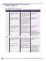
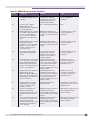
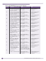
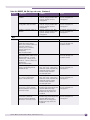
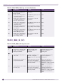
Table 1: Summit WM Controller WM20/WM200/2000 system capacities
Limit
WM2000
WM200
WM20
Max # of APs
200
100
32
Max throughput
2 Gbits/sec
2 Gbits/sec
400 Mbps
Max # of users (single controller)
4096
2048
512
Max # of users (multi-box/reserved)
4096
2048
512
Max # of VoIP calls
500
200
61-77 (G.711 at 20
ms)
Max # of WM-AD
64
32
8
Max # of routes
Total 10 000 routes
Total 5000 routes
Total 600 routes
Max # of static routes
1000
500
100
Max # of dynamic learnt routes
9000
4500
500
Max # of admin users
5
5
5
Max # of filter groups or filter
definitions
512
512
64
Max # of filter rules per group
128
128
64
Max# of total filter rules
60000
60000
16000
Max# routed VLANs
4
4
2
Max # of QoS profiles
128
64
16
Summit WM Controller WM100/WM1000
The following table specifies the performance capacities of the Summit WM Controller WM100/
WM1000 platforms.
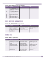
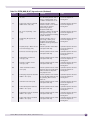
Table 2: Summit WM Controller WM100/WM1000 system capacities
Limit
WM1000
WM100
Max # of APs
200
75
Max throughput
2 Gbits/sec
400 Mbits/sec
Summit WM Technical Reference Guide, Software Version 5.3
13
System Capacities
Table 2: Summit WM Controller WM100/WM1000 system capacities (Continued)
Limit
WM1000
WM100
Max # of users (single controller)
4096
2048
Max # of users (multi-box/reserved)
4096
2048
Max # of VoIP calls
500
61-77
Max # of WM-AD
50
32
Max # of routes
10000
5000
Max # static routes
500
500
Max # dynamic learnt routes
9500
4500
Max # of admin users
5
5
Max # of filter rules per group
128
128
Max # of filter groups or filter definitions
512
512
Max# of total filter rules
16000
16000
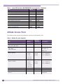
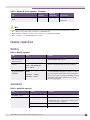
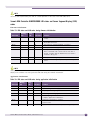
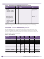
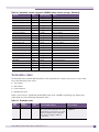
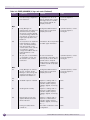
Altitude Access Point
The following table specifies the performance capacities of the Altitude™ APs.
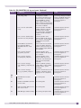
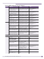
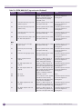
Table 3: Altitude AP system capacities
Limit
450/451
Outdoor AP
(2650/2660)
350-2i/350-2d
Max # 802.11 user associations per radio
127
127
127
Max # simultaneous transmissions per
radio (open, WEP, AES)
112
112
112
Max # simultaneous transmissions per
radio (TKIP)
(*See note below)
112
112
V3.x: 16
V4.x-V5R1: 24
V5R3: 112
Max throughput per radio type
Wired to Wireless
11b=6
11b=6
11b = 6 Mbits/sec
11g=26
11g=26
11g = 26 Mbits/sec
11a=26
11a=26
11a = 26 Mbits/sec
11b=6
11b=6
11b = 6 Mbits/sec
11g=24
11g=24
11g = 24 Mbits/sec
11a=24
11a=24
11a = 24 Mbits/sec
11a/n=147
11g/n=147
Max throughput per radio type
Wireless to Wired
11a/n=144
11g/n=144
14
Max # of SSIDs per radio
8
8
8
Max # MAC ACLs per AP
768
768
768
Max voice calls per radio Wireless to
wireless
11b=4
11b=4
11b=10
11b/g/a=34
Summit WM Technical Reference Guide, Software Version 5.3
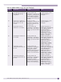
Table 3: Altitude AP system capacities (Continued)
Limit
450/451
Outdoor AP
(2650/2660)
350-2i/350-2d
Max voice calls per radio Wireless to
wired
11b=8
11b=8
11b=10
11b/g/a=34
NOTE
The maximum number of simultaneous transmissions per radio (TKIP) limits are version-dependent as follows:
• V3.x – Maximum 16 TKIP clients, maximum 112 WEP/AES/none
• V4.x/V5R0/V5R1– Maximum 24 TKIP clients, maximum 112 WEP/AES/none0149
• V5R3 – Maximum 112 TKIP/WEP/AES/none clients
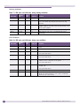
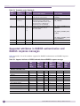
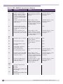
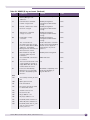
Feature capacities
Mobility
Table 4: Mobility capacities
Limit
Value
Comments
Max. # of Summit
WM Controllers per
mobility domain
12 (1 Manager + 11 Agents)
Mobility domains can consist of WM100/WM1000/
WM20/WM200/2000 platforms.
Max. # of systems
roamed
4096 – WM1000/WM2000
Each respective platform can accept only an equal
amount of users equivalent to its local capacity.
2048 – WM100/WM200
512 - WM20
Max. # of
aggregated mobility
bandwidth
1Gbps – WM1000, WM200/
2000
100 Mbps – WM100
200 Mbps - WM20
The maximum aggregated bandwidth is dependent
on the bandwidth of the physical interface on which
the inter-controller tunnel link is being established.
Note: In most cases the interface bandwidth is being
shared with other system operations (such as AP
tunnelling aggregation).
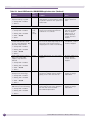
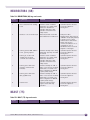
Availability
Table 5: Availability capacities
Limit
Values
Platforms
Max # systems per
availability cluster
2
Availability feature is supported in paired mode.
Max # APs per failover
200
WM1000/WM200/WM2000
Note:Failover limit is limited by the capacity of the
controller category in question
75
WM100
32
WM20
Summit WM Technical Reference Guide, Software Version 5.3
15
System Capacities
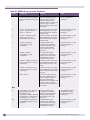
Table 5: Availability capacities (Continued)
Limit
Values
Platforms
Session availability failover
less than 5 seconds
WM200/WM2000
failover time
200 APs – 2 Minutes
WM1000/WM200/WM2000
75 APs – 1 Minute
WM100/WM200
4096
WM1000/WM2000
Max # users per failover
Note: Failover users capacity is restricted to the
number of Local users capacity of the system
undertaking the failover.
2048
WM100/WM200
512
WM20
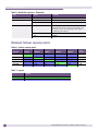
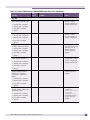
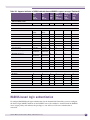
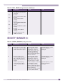
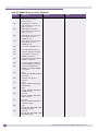
Maximum failover capacity matrix
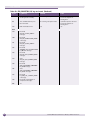
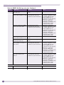
Table 6: Failover capacity matrix
Platforms
WM100
WM1000
WM20
WM200
WM2000
Local
Capacity
WM100
75
75
32
75
75
75
WM1000
75
200
32
100
200
200
WM20
32
32
32
32
32
32
WM200
75
200
32
100
200
100
WM2000
75
200
32
100
200
200
Table 7: Legend
Legend
16
Yes
All Summit WM Controllers within the same release (V5 R3).
Conditional
Number of APs allowed in failover is restricted by platform capacity.
Summit WM Technical Reference Guide, Software Version 5.3
2
Configuration of Dynamic Host Configuration
Protocol (DHCP)
Wireless AP Discovery supports the following methods:
●
Service Location Protocol (SLP)
●
Domain Name Server (DNS) – ext-summitwm-connect-1.<domainname>
●
Multicast – Same subnet multicast discovery
The listed discovery methods are tried in succession until a method is identified which produces a
successful registration with a controller. Static configuration can also be used for Wireless AP
registration. The static definition overrides any of the dynamic discovery methods.
For the Wireless AP’s process to discover the Summit WM Controller, the Summit WM Controller,
Access Points, and WM software system relies on a DHCP server that supports Option 78 and 79 for
Service Location Protocol (SLP). The combination of Dynamic Host Configuration Protocol (DHCP),
Option 78 and 79, and SLP provide a technique that defines the Summit WM Controller as the only
element on the network that the Wireless AP can communicate with.
Option 78 is a list of IP addresses of Directory Agents, used by Service Agents and Users Agents.
Option 79 is an identifier that refers to a set of services called a scope. If a User Agent is assigned to a
scope, it can only see the services in that scope, limiting the IP addresses of Directory Agents available
to the User Agent.
SLP assisted Wireless AP registration includes the following:
●
The Summit WM Controller Manager or the Wireless AP Manager use the Service Agent:
●
to look up the location of the Directory Agent using Option 78 and Option 79 in the DHCP server
●
to register with the Directory Agent
●
The Wireless AP User Agent looks up the location of the Directory Agent using Option 78 and
Option 79 in the DHCP server.
●
The Wireless AP User Agent contacts the Directory Agent for services of the types “Extreme”.
●
The Wireless AP attempts to connect with the Summit WM Controller or Wireless AP Manager.
Through discovery the Wireless AP identifies which Summit WM Controllers are available in it's local
area to provide service. The Wireless AP then registers with the Summit WM Controller using the CTP
protocol, a proprietary UDP based control, provisioning and tunneling protocol.
NOTE
SLP may also be used for inter-controller discovery, and in support of the inter-controller mobility feature.
Summit WM Technical Reference Guide, Software Version 5.3
17
Configuration of Dynamic Host Configuration Protocol (DHCP)
Service Location Protocol (SLP) (RFC2608)
Service Location Protocol (RFC2608) is a method of organizing and locating the resources (such as
printers, disk drives, databases, e-mail directories, and schedulers) in a network. Using SLP, networking
applications can discover the existence, location and configuration of networked devices.
In larger installations, services will register their services with one or more Directory Agents, and clients
will contact the Directory Agent to fulfill requests for Service Location information.
Service Location Protocol consists of three cooperating services:
●
User Agent (UA) – A process working on the user's behalf to acquire service attributes and
configuration. The User Agent retrieves service information from the Service Agents or Directory
Agents.
●
Service Agent (SA) –A process working on the behalf of one or more services to advertise service
attributes and configuration.
●
Directory Agent (DA) – A process which collects information from Service Agents to provide a
single repository of service information in order to centralize it for efficient access by User Agents.
There can only be one DA present per given host.
When a service starts on the network, its Service Agent queries the DHCP server for Option 78 and
Option 79 and registers itself appropriately.
DHCP Options for Service Location Protocol (RFC2610)
The Dynamic Host Configuration Protocol (RFC2131) provides a framework for passing configuration
information to hosts on a TCP/IP network.
Entities using the Service Location Protocol, Version 2 (RFC2608) and Service Location Protocol, Version
1 (RFC2165) must obtain the address of Directory Agents in order to transact messages. The SLP
Directory Agent option (Option 78) described in “SLP Directory Agent Option (Option 78)” on page 18
is used to configure User Agents and Service Agents with the location of Directory Agents in the
network.
The SLP Scope Option (Option 79) described in “SLP Service Scope Option (Option 79)” on
page 19provides an assignment of scope for configuration of SLP User and Service Agents. This option
takes precedence over both default and static scope configuration of SLP agents. A scope is a set of
services, typically making up a logical administrative group.
SLP Directory Agent Option (Option 78)
The SLP Directory Agent Option 78 specifies a list of IP addresses for SLP Directory Agents. Directory
Agents should be listed in order of preference. Summit WM Controllers register themselves as directory
agents.
The Length value must include one for the Mandatory byte and include four for each Directory Agent
address which follows. The address of the Directory Agent is given in network byte order. The
Mandatory byte in the Directory Agent option can be set to 0 or 1. If set to 1, the SLP User Agent or
18
Summit WM Technical Reference Guide, Software Version 5.3
Service Agent so configured must not employ either active or passive multicast discovery of Directory
Agents.
The Directory Agents listed in Option 78 must be configured with the a non-empty subset of the scope
list that the Agent receiving the Directory Agent Option 78 is configured with.
SLP Service Scope Option (Option 79)
Services are grouped together using scopes. Scopes are strings that identify a set of services that form an
administrative grouping. Service Agents (SAs) and Directory Agents (DAs) are always assigned a scope
string.
A User Agent (UA) is normally assigned a scope string (in which case the User Agent can only discover
that particular grouping of services). This allows a network administrator to provision services to users.
The use of scopes also allows the administrator to scale SLP deployments to larger networks.
The Scope-List String is a comma-delimited list of the scopes that a SLP Agent is configured to use. The
Length value must include one for the Mandatory byte. The Mandatory byte determines whether SLP
Agents override their static configuration for scopes with the <Scope List> string provided by the
option. This allows DHCP administrators to implement a policy of assigning a set of scopes to Agents
for service provision.
If the Mandatory byte is 0, static configuration takes precedence over the DHCP provided scope list. If
the Mandatory byte is 1, the <Scope List> provided in this option must be used by the SLP Agent. The
Scope List String usage is defined in the SLPv2 specification (RFC2608).
Summit WM Technical Reference Guide, Software Version 5.3
19
Configuration of Dynamic Host Configuration Protocol (DHCP)
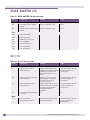
Dynamic Host Configuration Protocol – Summit WM
Controller and AP Discovery and other Services
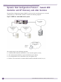
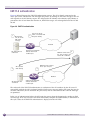
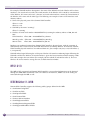
Dynamic Host Configuration Protocol (DHCP) can be used for several purposes in a network
configuration of a Summit WM Controller. Consider the following diagram:
Figure 1: DHCP in a Summit WM Controller system
Core network
a.b.c.d
AP deployment
network 1
e.f.g.h
AP deployment
network 2
i.j.k.l
DHCP
Wireless
laptop
Summit WM-AD
wireless network
w.x.y.z
This simple setup has the following properties:
20
●
A Summit WM Controller connected to a core network segment (a.b.c.d),
●
APs connected on both direct (e.f.g.h) and indirect (i.j.k.l) subnets,
●
An existing DHCP server somewhere in the core segment, and
●
Wireless users connected to a Summit WM Controller-controlled network (w.x.y.z).
Summit WM Technical Reference Guide, Software Version 5.3
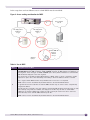
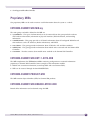
In this setup there are four different areas in which DHCP must be considered:
Figure 2: Areas needing consideration for DHCP
A
AP deployment
network 1
e.f.g.h
Core network
a.b.c.d
AP deployment
network 2
i.j.k.l
DHCP
C
B
D
Summit WM-AD
wireless
network
w.x.y.z
Wireless
laptop
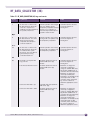
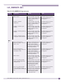
Table 8: Use of DHCP
Area
Description of use for DHCP
A
DHCP INFORM messages are periodically sent on all physical ports (esa0-1 on WM1000, esa0-3 on
WM200/2000 Summit WM Controllers). DHCP INFORM messages are NOT requests for addressing on
that segment. These messages use DHCP INFORM option 78 to provide information to other Summit
WM Controllers deployed on the same segment.
For setups that use multiple Summit WM Controllers a DHCP server in area A is required to answer
requests for option 78 to allow availability and mobility to work. No addresses will be consumed.
For a single Summit WM Controller setup a DHCP server in this area is not required.
DHCP services for this area MUST be provided external to the Summit WM Controller.
B
In general APs that are used with the Summit WM Controller may use either a static or dynamically
assigned IP address.
For APs that are connected to the same subnet as the Summit WM Controller initial discovery can take
place directly using multicast. However, the deployer of the APs may still wish to utilize DHCP
addressing for the APs. Additionally, support for option 78 may be used in this area to aid in the
initial discovery of the Summit WM Controller by the APs.
DHCP services for this area MUST be provided external to the Summit WM Controller.
Summit WM Technical Reference Guide, Software Version 5.3
21
Configuration of Dynamic Host Configuration Protocol (DHCP)
Table 8: Use of DHCP (Continued)
Area
Description of use for DHCP
C
For AP deployment networks that are not in the same subnet as the Summit WM Controller there
needs to be some mechanism to allow the APs to find the Summit WM Controller across subnet. The
APs can use a static list of Summit WM Controllers to connect to or use DNS but by far the most
common method is to allow them to use DHCP option 78 to locate a service location protocol (SLP)
director agent that is generally hosted on the Summit WM Controller itself.
In addition, the APs themselves may also be addressed via DHCP in this area.
DHCP services for this area MUST be provided external to the Summit WM Controller.
D
DHCP services in area D is for WLAN clients. A separate scope for each SSID is required.
DHCP services for this area are provided by default by the Summit WM Controller. DHCP services can
also be relayed to an external DHCP server.
DHCP setup using the internal DHCP server
For simple DHCP setups it is recommended to use the Summit WM Controller’s built-in DHCP server.
The internal DHCP server is intended to provide WLAN clients with IP addresses. The internal DHCP
server settings are available in the Summit WM Graphical User Interface (GUI) under WM-AD Topology. This page allows for the configuration of the following options for DHCP:
Table 9: Internal DHCP setup
Screen Item
Description
Gateway:
The user-configured IP address of the interface attachment on that subnet.
Mask:
The netmask for the network
Address range:
The overall range of available IP addresses. This has a default value based on the
Gateway IP address.
Exclusions:
Any IP addresses to be excluded from the address range. Multiple entries are
permitted.
Broadcast address:
The broadcast address. This value cannot be changed. It is automatically calculated.
Domain name:
The domain name to hand out to the client. If the domain name is
wireless.aDRM.com and the client hostname is laptop then the FQDN for the client
using this network will be laptop.wireless.aDRM.com.
Lease default:
The default lease time in seconds. The default is 36000 (10 hours).
Lease max:
The maximum lease time in seconds. The default is 2592000 (30 days).
DNS servers:
A single or list of DNS servers to give the DHCP client. Use a comma to separate
multiple entries on this line.
WINS:
A single or multiple WINS servers to give the DHCP client. Use a comma to separate
multiple entries
The major benefit of using the internal DHCP server is that all DHCP messages from clients are logged
and available in the GUI under Logs & Traces - DHCP messages.
For the inclusion of options that are not supported within this layout it is recommend to use DHCP
relay.
22
Summit WM Technical Reference Guide, Software Version 5.3
Using the Summit WM Controller as the default DHCP
server
You can use the Summit WM Controller as the default DHCP server. This feature allows the controller
to act as a DHCP server for the Altitude AP. The Summit WM Controller can also be used as a general
DHCP server.
The Summit WM Controller’s DHCP server is configured to ensure DHCP requests made to the esa
ports are properly responded to. Each physical port can be configured separately.
When DCHP is enabled on a physical port, the DHCP options become available for configuration.
(These options are identical to the DHCP options available to WM-ADs using the local DHCP server.)
Table 10: Summit WM Controller as default DHCP server
Screen Item
Description
Address range
The overall range of available IP addresses. This has a default value based on the IP
address of the physical port.
Exclusions
Any IP addresses to be excluded from the address range. Multiple entries are permitted.
Range from
The start of a range of excluded IP addresses or a single IP address to be excluded.
Range to
The end of a range of excluded IP addresses. This is optional.
Comment
A comment about an exclusion range. This is optional.
Gateway
The default gateway. This has a default value based on the IP address of the physical
port.
Broadcast address
The broadcast address. This value cannot be changed. It is automatically
calculated.
Domain name
The domain name that Wireless APs will use for DNS Server’s discovery. This is optional.
Lease
The time that an IP address will be allocated to a Wireless AP, measured in seconds.
Default
The time that an IP address will be allocated to a Wireless AP, measured in seconds.
Max
The maximum time that an IP address will be allocated to a Wireless AP, measured in
seconds.
DNS servers
The DNS Server’s IP address. This is optional.
WINS
The WINS Server’s IP address. This is optional.
DHCP setups for relayed WM-AD’s and AP deployment
networks
Sometimes it is necessary to use a DHCP server external from the Summit WM Controller to offer
DHCP addresses. Popular reasons for this are:
●
Support for DHCP options that are not exposed through Summit WM Controller GUI (Summit WM
GUI),
●
To leverage existing DHCP infrastructures, and
●
To consolidate the DHCP requirements for wireless client, APs, and the Summit WM Controller in
one place.
Summit WM Technical Reference Guide, Software Version 5.3
23
Configuration of Dynamic Host Configuration Protocol (DHCP)
The limitation of using DHCP relay comes in the logging of DHCP messages on the Summit WM
Controller. When using DHCP relay the DHCP log under Logs & Traces Æ DHCP Messages is not
populated with DHCP requests. It is assumed that for DHCP relay that the target DHCP server has its
own logging mechanism.
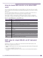
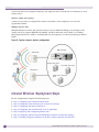
DHCP configuration example: OSC dhcpd on Linux
Consider the following topology:
Figure 3: Topology for DHCP example
Network 10.0.0.0/24
10.0.0.10
DCHP
10.0.0.9
AP assigned by
DHCP
Summit WM-AD
wireless network
172.16.2.0/24
Voice gateway
10.0.0.11
Summit WM-AD
wireless network
172.16.1.0/24
Wireless laptop
The Summit WM Controller is connected on network 10.0.0.0/24 as 10.0.0.10. Also on that network are a
DHCP server, a voice gateway for phones, and all Access Points. The phones have the special property
in that they require DHCP option 151 to find their voice gateway. Since the Summit WM Controllerbuilt-in DHCP server does not support custom options is was decided to use a Linux server at 10.0.09 to
host all DHCP requirements for this network. It is possible to configure each WM-AD to use DHCP
relay to the example DHCP server of 10.0.0.9.
24
Summit WM Technical Reference Guide, Software Version 5.3
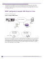
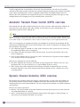
The following is the configuration file dhcpd.conf from the Linux server at 10.0.0.9:
Figure 4: dhcpd.conf example listing
This file can be divided into the following four areas:
●
General options: lines 1-3
●
Scope for 10.0.0.0/24 subnet: lines 4-8
●
Scope for 172.16.1.0/24 subnet (voice subnet): lines 9-18
●
Scope for 172.16.2.0/24 subnet (laptop subnet): lines 19-27
Summit WM Technical Reference Guide, Software Version 5.3
25
Configuration of Dynamic Host Configuration Protocol (DHCP)
General options
Line 1 designates this DHCP server as authoritative in case another DHCP server answers requests.
Line 2 sets options for Dynamic DNS. This option turns off DNS updates based upon DHCP mappings.
There are other options that allow DHCP to update a DNS server to reflect the addresses handed out by
the DHCP server. See the man page for dhcpd.conf for more information on support for this option.
Line 3 defines the format for DHCP option 151 as we want to use it. The phones being used on one of
the wireless networks in this example require this option to find their voice gateway. Since the Summit
WM Controller does not allow for custom options this is the perfect place to insert this option.
Scope 10.0.0.0/24 (lines 4-8)
This scope is primarily defined to allow APs deployed in the same subnet to acquire an IP address. Also
defined in this subnet is the option slp-directory-agent – this is option number 78 and allows the APs to
find the Summit WM Controller by Service Location Protocol. It also allows a multiple Summit WM
Controller setup that includes availability and mobility.
Notice that the static addresses in the topology use host addresses whose last octet is less than 50. The
definition in the file specifically will address APs only from address 50-254 within this subnet. Thus, the
static addresses used by the infrastructure elements are protected from use by the DHCP-enabled APs.
Scope 172.16.1.0/24 (lines 9-18)
This scope is defined to address wireless handsets. Notice the use of option 151 (now called ‘svp’ within
the scope). Delivery of this option would be impossible from the Summit WM Controller itself but it can
be delivered through DHCP relay. The other options are self-explanatory.
Scope 172.16.2.0/24 (line 19-27)
This scope is defined to address general wireless devices using a separate SSID on the same system that
the voice clients are deployed on. The options within this scope are very simple – see the dhcpd.conf
and dhcpd-options man pages within Linux to review the variety of options that are available to be
handed out to DHCP clients within your network.
Altitude Access Point Discovery mechanism
The following outlines an advanced version of our Altitude Access Point discovery mechanism. Note
that this document only applies to the mechanism for discovering the IP address or addresses of the
Summit WM Controller or set of Summit WM Controllers that may provide service to a particular
Wireless AP. It does not include a description of or make any assumptions about the mechanism to
“connect” to a Summit WM Controller or of any failover scenarios for Summit WM Controller
connection.
26
Summit WM Technical Reference Guide, Software Version 5.3
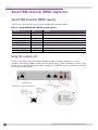
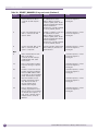
Wireless AP DHCP Registration Setup (WINDOWS)
You can configure the DHCP service that is included with Windows 2000 and Windows 2003 to provide
DHCP option 78. Extreme Networks Altitude APs (Wireless AP) as clients to the Summit WM
Controller (Summit WM Controller) may require the configuration of DHCP options 78 for controller
discovery. These options are sometimes referred to as the SLP options. The SLP options (from Request
for Comments [rfc] 2610) have an extra flag in the option field that is different than any other DHCP
option. This flag is called the Mandatory byte. No other DHCP options for simple address arrays follow
this structure.
The following example compares SLP options to DCHP options:
SLP options:
| Code = 78 | Length | Mandatory | a1 | a2 | a3 | a4 |...
All other DHCP options:
| Code = 32 | Length | a1 | a2 | a3 | a4 |...
This extra 5th byte prevents you from using the IPAddress array type in the snap-in when you add this
option. However, you can add the option by creating option 78 as a Byte array.
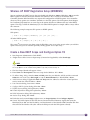
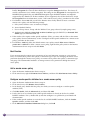
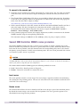
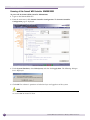
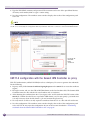
Create a New DHCP Scope and Configure Option 78
1 Start Programs Administrative Tools DHCP
2 <Right mouse click> Server or Superscope (if created and applicable) select New Scope.
NOTE
If you wish to use an existing scope and all that you wish to do is add the SLP option; <right mouse click> on
the Scope Options of the related existing DHCP scope and proceed to Step 13.
3 The New Scope Wizard will appear <Next>
4 Enter Name and Description of the new scope for the Wireless AP’s <Next>
5 IP Address Range dialog; select the Start and End points for your Wireless AP IPs and the associated
Subnet in one of two ways Bit Length (ex. 24) or Dotted Decimal (ex. 255.255.255.0) <Next>.
6 Add Exclusions dialog; If applicable Start and End points for addresses within the created pool that
need to retain the same IP address. <Next>
7 Lease Duration dialog; Lease times <Next>
8 Configure DHCP Options dialog; Select Yes <Next>
9 Default Gateway dialog; Self explanatory <Next>
10 Domain Information dialog; Self explanatory <Next>
11 WINS Information dialog; Self explanatory <Next>
12 Activate Scope dialog; Yes <Next>
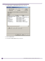
13 Under the newly created Scope <right mouse> on Scope Options select Configure Options
14 General Tab; Select Option 78 SLP DA (Service Location Protocol Directory Agent) then enter the
Mandatory byte “00” and the IP address <in Hexadecimal> of the Summit WM Controller ESA Port
that will host the Wireless APs (this will be the ESA port with the SLP Option selected).
Summit WM Technical Reference Guide, Software Version 5.3
27
Configuration of Dynamic Host Configuration Protocol (DHCP)
NOTE
It is also possible to attend to this using Dotted Decimal form.
For example, for the controller ESA Port IP address 10.53.0.1, additions should be made in hexadecimal
format 00 <lead byte> 0A 35 00 01 <IP address>
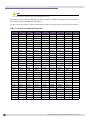
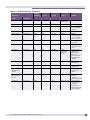
For the sake of convenience a quick reference chart follows for the decimal to hexadecimal conversions.
Table 11: Decimal to Hexadecimal Conversions
28
Dec-Hex
Dec-Hex
Dec-Hex
Dec-Hex
Dec-Hex
Dec-Hex
Dec-Hex
Dec-Hex
Dec-Hex
0 - 00
31-1F
62-3E
93-5D
124-7C
155-9B
186-BA
217-D9
248-F8
1 - 01
32-20
63-3F
94-5E
125-7D
156-9C
187-BB
218-DA
249-F9
2 - 02
33-21
64-40
95-5F
126-7E
157-9D
188-BC
219-DB
250-FA
3 - 03
34-22
65-41
96-60
127-7F
158-9E
189-BD
220-DC
251-FB
4 - 04
35-23
66-42
97-61
128-80
159-9F
190-BE
221-DD
252-FC
5 - 05
36-24
67-43
98-62
129-81
160-A0
191-BF
222-DE
253-FD
6 - 06
37-25
68-44
99-63
130-82
161-A1
192-C0
223-DF
254-FE
7 - 07
38-26
69-45
100-64
131-83
162-A2
193-C1
224-E0
255-FF
8 - 08
39-27
70-46
101-65
132-84
163-A3
194-C2
225-E1
9 - 09
40-28
71-47
102-66
133-85
164-A4
195-C3
226-E2
10-0A
41-29
72-48
103-67
134-86
165-A5
196-C4
227-E3
11-0B
42-2A
73-49
104-68
135-87
166-A6
197-C5
228-E4
12-0C
43-2B
74-4A
105-69
136-88
167-A7
198-C6
229-E5
13-0D
44-2C
75-4B
106-6A
137-89
168-A8
199-C7
230-E6
14-0E
45-2D
76-4C
107-6B
138-8A
169-A9
200-C8
231-E7
15-0F
46-2E
77-4D
108-6C
139-8B
170-AA
201-C9
232-E8
16-10
47-2F
78-4E
109-6D
140-8C
171-AB
202-CA
233-E9
1711
48-30
79-4F
110-6E
141-8D
172AC
203-CB
234-EA
18-12
49-31
80-50
111-6F
142-8E
173-AD
204-CC
235-EB
19-13
50-32
81-51
112-70
143-8F
174-AE
205-CD
236-EC
20-14
51-33
82-52
113-71
144-90
175-AF
206-CE
237ED
21-15
52-34
83-53
114-72
145-91
176-B0
207-CF
238-EE
22-16
53-35
84-54
115-73
146-92
177-B1
208-D0
239-EF
23-17
54-36
85-55
116-74
147-93
178-B2
209-D1
240-F0
24-18
55-37
86-56
117-75
148-94
179-B3
210-D2
241-F1
25-19
56-38
87-57
118-76
149-95
180-B4
211-D3
242-F2
26-1A
57-39
88-58
119-77
150-96
181-B5
212-D4
243-F3
27-1B
58-3A
89-59
120-78
151-97
182-B6
213-D5
244-F4
28-1C
59-3B
90-5A
121-79
152-98
183-B7
214-D6
245-F5
29-1D
60-3C
91-5B
122-7A
153-99
184-B8
215-D7
246-F6
30-1E
61-3D
92-5C
123-7B
154-9A
185-B9
216-D8
247-F7
Summit WM Technical Reference Guide, Software Version 5.3
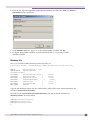
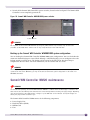
DNS Settings for Altitude AP Discovery
There is an assumption that for the use of this mechanism that there are DNS services configured and
available.
1 Start Programs Administrative Tools DNS
2 <Right mouse click> Domain that will be used for discovery, select New Host (W2K Server) New
Host (A) (W2003 server)
3 First field enter ext-summitwm-connect-1 which is the default name for the Extreme Networks
Summit WM Controller, then enter the IP address of the WM ESA port that will host the Wireless
AP connections.
4 Select Create Pointer <Finish>. This will create a pointer and append the WM reference “extsummitwm-connect-1” to the existing domain string to create the host record and in turn the
“Forward Lookup” for the Wireless APs to discover the Summit WM Controller.
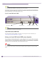
Static Altitude AP Addressing
If an Altitude AP is configured to use a static IP address, it will always use the configured static IP
address and will not use the default IP address.
●
To configure a static IP address, power up the Altitude AP, connect the Altitude AP to a laptop, and
then ping the Altitude AP’s default IP address. You have approximately 60 seconds to establish a
connection to the Altitude AP.
●
If the ping is successful, telnet the Altitude AP and configure the static IP address of the Altitude AP.
●
If the Altitude AP is not configured, the Altitude AP retains its default IP address and begins the
discovery process. The Altitude AP will retain the default IP address until configured otherwise.
Summit WM Technical Reference Guide, Software Version 5.3
29
Configuration of Dynamic Host Configuration Protocol (DHCP)
30
Summit WM Technical Reference Guide, Software Version 5.3
3
Rogue Access Point Detection
The rogue AP detection feature, Summit WM series Spy, provides capabilities to Summit WM
Controllers that allow Wireless APs to periodically scan the RF space and report suspect devices. With
this capability, Wireless APs can multitask as scan devices as well as access points. This allows rogue
detection to occur without installing overlay sensor networks. Summit WM Controllers Rogue detection
system is comprised of two major components; the Data Collector and the Analysis Engine.
The Data Collector runs on every Summit WM Controller and is responsible for initiating the rogue
scans and compiling information received from all Wireless APs under its control.
The Analysis Engine is the brains of this feature and runs on one Summit WM Controller in the
network. It polls all Data Collectors periodically (default is every 5 seconds) and analyzes the polled
data to identify new devices. It also uses the polled data to build a table of known “friendly” Wireless
APs and 3rd Party Access Points. On subsequent scans, new devices are identified and compared to the
“friendly” list and differences are flagged as potential Rogues. The Analysis Engine also includes a GUI
to allow users to manually add or remove devices from the system or redefine a device identified as a
potential rogue into a “friendly” if the proper designation of a device is determined.
A Wireless AP is assigned to a “scan group” that has a particular set of “scan parameters. Different
groups can be defined so that the administrator can assign Wireless AP’s to logical groups to address
either different geographic needs (that is, only scan certain buildings at certain times) or coverage issues
(only scan with half of the Wireless APs in a given area at a given time). An Altitude AP can only be
assigned to one group. The algorithms and mechanisms for RF scanning have been designed to
minimize the impact on user data. Also, the GUI provides the ability for an administrator to configure
the frequency at which the Wireless AP’s within a scan group will initiate a scan (minimum 10 minutes,
and maximum 120 minutes)
Upon completion of the scan, the Wireless AP will send back the results to the Summit WM Controller
and then wait for the next “scan interval” to repeat the process.
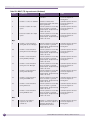
If a problem is found, an event is logged and an SNMP trap is generated indicating one of the following
conditions has been identified:
1 Unknown AP with an invalid SSID – Critical Alarm
A new device has been identified
2
Unknown AP with a valid SSID – Critical Alarm
Someone may be trying to attract users by broadcasting a known SSID.
3 Known AP with an invalid SSID – Critical Alarm
A Rogue may be spoofing a know MAC address.
4 Known Wireless AP with an invalid SSID– Major Alarm
A Rogue may be spoofing a Wireless AP using a known MAC address.
5 Device that is in ad-hoc mode (IBSS) – Major Alarm
A client configured in ad-hoc mode has been identified
6 Inactive Wireless AP with known SSID – Major Alarm
A “known” Wireless AP has been detected that the Summit WM Controller has identified as not in
service (stolen?)
Summit WM Technical Reference Guide, Software Version 5.3
31
Rogue Access Point Detection
7
Inactive Wireless AP with unknown SSID – Major Alarm
A “known” Wireless AP with an unknown SSID has been detected that the Summit WM Controller
has identified as not in service (stolen?)
8 Known AP with Valid SSID Suppress Conflict – Critical Alarm
A “known” Altitude AP with a valid SSID has been detected, however the configured AP is not
broadcasting the SSID value (suppressed). Instead, the rogue device is broadcasting the SSID.
With each event, the following information will be reported:
●
Scanning Wireless AP Name & Scan Group
●
Detection Date and Time
●
Rogue SSID and Channel
●
Signal Strength (RSSI)
●
Security/Encoding type (for example. WEP, 802.1X, none, and so on)
This information is available through SNMP, or by viewing a report displayed in the Summit WM GUI.
In addition, a summary screen is provided as a pop-up window that provides a summary of all
potential problem areas on a single screen.
NOTES: A Few Points Related to Summit WM series Spy and Rogue Systems in General.
32
●
Due to the fact that accuracy is suspect, an administrator will more than likely still have to hunt the
rogue in person with a handheld/laptop to find the exact location. So, even using just the Summit
WM Controller’s Summit WM series Spy information (mentally weigh and plot RSSI values from the
scan group APs) an administrator can locate a rogue just as easily as with graphic tools.
●
Some other systems address rogue APs with a function known as “containment”. The effectiveness
of containment may vary due to some inherent limitations of this method. For example, most
containment is done via RF bombardment or via a ping DOS to the rogue device. Unless WLAN
gear uses very directional or phased array antenna systems, the bombardment is not discriminating
and will impact every device (MUs included) in close proximity. Also, if a rogue containment AP is
launching an attack (for containment) the service expectation of the client may be impacted. And
finally, because WiFi works in an UNLICENSED spectrum, a rogue containment system may
inadvertently attack a co-existing, legitimate system operating in an open spectrum.
Summit WM Technical Reference Guide, Software Version 5.3
4
Creating the Windows Security Infrastructure
To ensure information and best practice configuration integrity, all information contained in this section
was extracted from this source:
●
“Deploying Secure 802.11 Wireless Networks with Microsoft Windows”, by Joseph Davies
http://www.microsoft.com/technet/prodtechnol/winxppro/deploy/ed80211.mspx
Wireless client computers running Windows:
Windows XP and Windows Server 2003 have built-in support for IEEE 802.11 wireless access and IEEE
802.1X authentication using the Extensible Authentication Protocol (EAP). Windows 2000 supports IEEE
802.1X authentication when either Windows 2000 Service Pack 4 (SP4) or Windows 2000 Service Pack 3
(SP3) and Microsoft 802.1X Authentication Client is installed (Windows 2000 SP4 is recommended).
At least two Internet Authentication Service (IAS) servers:
At least two IAS servers (one primary and one secondary) are used to provide fault tolerance for
Remote Authentication Dial-In User Service (RADIUS)-based authentication. If only one RADIUS server
is configured and it becomes unavailable, wireless access clients cannot connect. By using two IAS
servers and configuring all wireless access points (APs) (the RADIUS clients) for both the primary and
secondary IAS servers, the RADIUS clients can detect when the primary RADIUS server is unavailable
and automatically fail over to the secondary IAS server.
You can use either Windows Server 2003 or Windows 2000 Server IAS. IAS servers running Windows
2000 must have either SP4 or SP3 with Microsoft 802.1X Authentication Client installed (Windows 2000
SP4 is recommended). IAS is not included with Windows Server 2003, Web Edition
Active Directory® directory service domains:
Active Directory domains contain the user accounts, computer accounts, and dial-in properties that each
IAS server requires to authenticate credentials and evaluate authentication. While not a requirement, to
both optimize IAS authentication and authentication response times and minimize network traffic, IAS
should be installed on Active Directory domain controllers. You can use either Windows Server 2003 or
Windows 2000 Server domain controllers. Windows 2000 domain controllers must have SP3 or SP4
installed.
Computer certificates installed on the IAS servers:
Regardless of which wireless authentication method you use, you must install computer certificates on
the IAS servers.
For EAP-TLS authentication, a certificate infrastructure:
When the Extensible Authentication Protocol-Transport Level Security (EAP-TLS) authentication
protocol is used with computer and user certificates on wireless clients, a certificate infrastructure, also
known as a public key infrastructure (PKI), is needed to issue certificates
For Protected EAP (PEAP) with Microsoft Challenge Handshake Authentication Protocol version 2 (MSCHAP v2) authentication, root certification authority (CA) certificates on each wireless client. PEAP-MSCHAP v2 is a password-based secure authentication method for wireless connections. Depending on the
Summit WM Technical Reference Guide, Software Version 5.3
33
Creating the Windows Security Infrastructure
issuer of the IAS server computer certificates, you might also have to install root CA certificates on each
wireless client.
Wireless remote access policy:
A remote access policy is configured for wireless connections so that employees can access the
organization intranet.
Multiple wireless APs:
Multiple third-party wireless APs provide wireless access in different buildings of an enterprise. The
wireless APs must support IEEE 802.1X, RADIUS, and Wi-Fi Protected Access (WPA™) or WPA2™.
Wired Equivalent Privacy (WEP) is recommended only for temporary use when transitioning to WPA or
WPA2.
Figure 5: Typical enterprise wireless configuration
WM Controller
Altitude AP
Client
devices
Primary IAS server
Secondary IAS server
Altitude AP
Certification authority
(CA)
Intranet Wireless Deployment Steps
For this configuration, complete the following steps:
34
●
Step 1: Configuring the Certificate Infrastructure
●
Step 2: Configuring Active Directory for Accounts and Groups
●
Step 3: Configuring the Primary IAS Server
●
Step 4: Configuring the secondary IAS server (if applicable)
●
Step 5: Deploying and Configuring Wireless APs.
●
Step 6: Configuring Wireless Network (IEEE 802.11) Policies Group Policy Settings
●
Step 7: Installing Computer Certificates on Wireless Client Computers for EAP-TLS
Summit WM Technical Reference Guide, Software Version 5.3
●
Step 8: Installing User Certificates on Wireless Client Computers for EAP-TLS
●
Step 9: Configuring Wireless Clients for EAP-TLS
●
Step 10: Configuring Wireless Client Computers for PEAP-MS-CHAP v2
Step 1: Configuring the Certificate Infrastructure
Table 12 summarizes the certificates needed for the different types of authentication.
Table 12: Authentication types and certificates
Authentication Type
Certificates on Wireless Client
Certificates on IAS Server
EAP-TLS
Computer certificates
Computer certificates
User certificates
Root CA certificates for issuers of
wireless client computer and user
certificates
Root CA certificates for issuers of IAS server
computer certificates
PEAP-MS-CHAP v2
Root CA certificates for issuers of IAS server
computer certificates
Computer certificates
●
Regardless of which authentication method you use for wireless connections, EAP-TLS or PEAP-MSCHAP v2, you must install computer certificates on the IAS servers.
●
For PEAP-MS-CHAP v2, you do not have to deploy a certificate infrastructure to issue computer and
user certificates for each wireless client computer. Instead, you can obtain individual certificates for
each IAS server in your enterprise from a commercial certification authority and install them on the
IAS servers.
●
For more information, see “Step 3: Configuring the Primary IAS Server” and “Step 4: Configuring
the Secondary IAS Server” in this article. Windows wireless clients include a number of root CA
certificates for well known and trusted commercial CAs. If you obtain computer certificates from
a commercial CA for which there is already an installed root CA certificate, there are no
additional certificates to install on the Windows wireless clients.
●
If you obtain computer certificates from a commercial CA for which there is not already an
installed root CA certificate, you must install the root CA certificates for the issuers of the
computer certificates installed on the IAS servers on each Windows wireless client. For more
information, see “Step 10: Configuring Wireless Client Computers for PEAP-MS-CHAP v2” in
this article.
●
For computer authentication with EAP-TLS, you must install a computer certificate, also known as a
machine certificate, on the wireless client computer. A computer certificate installed on the wireless
client computer is used to authenticate the wireless client computer so that the computer can obtain
network connectivity to the enterprise intranet and computer configuration Group Policy updates
prior to user login. For user authentication with EAP-TLS after a network connection is made and
the user logs in, you must use a user certificate on the wireless client computer.
●
The computer certificate is installed on the IAS server computer so that during EAP-TLS
authentication, the IAS server has a certificate to send to the wireless client computer for mutual
authentication, regardless of whether the wireless client computer authenticates with a computer
certificate or a user certificate. The computer and user certificates submitted by the wireless client
and IAS server during EAP-TLS authentication must conform to the requirements specified in
“Using a Third-Party CA” in this article.
●
In Windows Server 2003, Windows XP, and Windows 2000, you can view the certificate chain from
the Certification Path tab in the properties of a certificate in the Certificates snap-in. You can view
Summit WM Technical Reference Guide, Software Version 5.3
35
Creating the Windows Security Infrastructure
the installed root CA certificates in the Trusted Root Certification Authorities\Certificates folder and
you can view the intermediate CA certificates in the Intermediate Certification
Authorities\Certificates folder.
●
In a typical enterprise deployment, the certificate infrastructure is configured using single root CA in
a three-level hierarchy consisting of root CA/intermediate CAs/issuing CAs. Issuing CAs are
configured to issue computer certificates or user certificates. When the computer or user certificate is
installed on the wireless client, the issuing CA certificate, intermediate CA certificates, and the root
CA certificate is also installed. When the computer certificate is installed on the IAS server computer,
the issuing CA certificate, intermediate CA certificates, and the root CA certificate is also installed.
The issuing CA for the IAS server certificate can be different than the issuing CA for the wireless
client certificates. In this case, both the wireless client and the IAS server computer have all the
required certificates to perform certificate validation for EAP-TLS authentication.
Best Practices
●
If you are using EAP-TLS authentication, use both user and computer certificates for both user and
computer authentication.
●
If you are using EAP-TLS authentication, do not also use PEAP-TLS. Allowing both protected and
unprotected authentication traffic for the same type of network connection renders the protected
authentication traffic susceptible to spoofing attacks.
●
If you already have a certificate infrastructure for EAP-TLS authentication and are using RADIUS for
dial-up or virtual private network (VPN) remote access connections, you can skip some of the
certificate infrastructure steps. You can use the same certificate infrastructure for wireless
connections. However, you must ensure that computer certificates are installed for computer
authentication.
●
For computers running Windows XP with no service packs installed, you must have user certificates
stored on the computer for user authentication (rather than using smart cards).
●
For computers running Windows Server 2003, Windows XP with Service Pack (SP1), Windows XP
with Service Pack 2 (SP2), or Windows 2000, you can use either user certificates stored on the
computer or a smart card for user authentication.
Step 1a: Installing a Certificate Infrastructure
When installing a certificate infrastructure, use the following best practices:
36
●
Plan your public key infrastructure (PKI) before deploying CAs.
●
The root CA should be offline and its signing key should be secured by a Hardware Security Module
(HSM) and kept in a vault to minimize potential for key compromise.
●
Enterprise organizations should not issue certificates to users or computers directly from the root
CA, but rather should deploy the following:
●
An offline root CA
●
Offline intermediate CAs
●
Online issuing CAs (using Windows Server 2003 or Windows 2000 Certificate Services as an
enterprise CA)
●
This CA hierarchy provides flexibility and insulates the root CA from attempts to compromise its
private key by malicious users. The offline root and intermediate CAs do not have to be Windows
Server 2003 or Windows 2000 CAs. Issuing CAs can be subordinates of a third party intermediate
CA.
Summit WM Technical Reference Guide, Software Version 5.3
●
Backing up the CA database, the CA certificate, and the CA keys is essential to protect against the
loss of critical data. The CA should be backed up on a regular basis (daily, weekly, monthly) based
on the number of certificates issued over the same interval. The more certificates issued, the more
frequently you should back up the CA.
●
You should review the concepts of security permissions and access control in Windows, since
enterprise CAs issue certificates based on the security permissions of the certificate requester.
Additionally, if you want to take advantage of autoenrollment for computer certificates, use Windows
2000 or Windows Server 2003 Certificate Services and create an enterprise CA at the issuer CA level. If
you want to take advantage of autoenrollment for user certificates, use Windows Server 2003, Enterprise
Edition, or Windows Server 2003, Datacenter Edition, Certificate Services and create an enterprise CA at
the issuer CA level.
By default, the IAS server checks for certificate revocation for all the certificates in the certificate chain
sent by the wireless client during the EAP-TLS authentication process. If certificate revocation fails for
any of the certificates in the chain, the connection attempt is not authenticated and is denied. The
certificate revocation check for a certificate can fail because of the following:
●
The certificate has been revoked, The issuer of the certificate has explicitly revoked the certificate.
●
The certificate revocation list (CRL) for the certificate is not reachable or available.
●
CAs maintain CRLs and publish them to specific CRL distribution points. The CRL distribution
points are included in the CRL Distribution Points property of the certificate. If the CRL
distribution points cannot be contacted to check for certificate revocation, then the certificate
revocation check fails.
●
Additionally, if there are no CRL distribution points in the certificate, the IAS server cannot verify
that the certificate has not been revoked and the certificate revocation check fails.
●
The publisher of the CRL did not issue the certificate.
●
Included in the CRL is the publishing CA. If the publishing CA of the CRL does not match the
issuing CA for the certificate for which certificate revocation is being checked, then the certificate
revocation check fails.
●
The CRL is not current
●
Each published CRL has a range of valid dates. If the CRL Next update date has passed, the CRL
is considered invalid and the certificate revocation check fails. New CRLs should be published
before the expiration date of the last published CRL
Because certificate revocation checking can prevent wireless access due to the unavailability or
expiration of CRLs for each certificate in the certificate chain, design your PKI for high availability of
CRLs. For instance, configure multiple CRL distribution points for each CA in the certificate hierarchy
and configure publication schedules that ensure that the most current CRL is always available.
Certificate revocation checking is only as accurate as the last published CRL. For example, if a certificate
is revoked, by default the new CRL containing the newly revoked certificate is not automatically
published. CRLs are typically published based on a configurable schedule. This means that the revoked
certificate can still be used to authenticate because the published CRL is not current; it does not contain
the revoked certificate and can therefore still be used to create wireless connections. To prevent this
from occurring, the network administrator must manually publish the new CRL with the newly
revoked certificate.
By default the IAS server uses the CRL distribution points in the certificates. However, it is also possible
to store a local copy of the CRL on the IAS server. In this case, the local CRL is used during certificate
revocation checking. If a new CRL is manually published to the Active Directory, the local CRL on the
IAS server is not updated. The local CRL is updated when it expires. This can create a situation wherein
Summit WM Technical Reference Guide, Software Version 5.3
37
Creating the Windows Security Infrastructure
a certificate is revoked, the CRL is manually published, but the IAS server still allows the connection
because the local CRL has not yet been updated.
Step 1b: Installing Computer Certificates
If you are using a Windows Server 2003 or Windows 2000 Certificate Services enterprise CA as an
issuing CA, you can install a computer certificate on the IAS server by configuring Group Policy for the
autoenrollment of computer certificates for computers in an Active Directory system container.
To configure computer certificate enrollment for an enterprise CA:
1 Open the Active Directory Users and Computers snap-in.
2 In the console tree, double-click Active Directory Users and Computers, right-click the domain
name to which your CA belongs, and then click Properties
3 On the Group Policy tab, click the appropriate Group Policy object (the default object is Default
Domain Policy), and then click Edit.
4 In the console tree, open Computer Configuration, then Windows Settings, then Security Settings,
then Public Key Policies, then Automatic Certificate Request Settings.
5 Right-click Automatic Certificate Request Settings, point to New, and then click Automatic
Certificate Request.
6 The Automatic Certificate Request wizard appears. Click Next.
7 In Certificate templates, click Computer, and then click Next. Your enterprise CA appears on the list
8 Click the enterprise CA, click Next, and then click Finish.
9 To immediately obtain a computer certificate for the CA that is running Windows 2000 Server, type
the following at a command prompt: secedit /refreshpolicy machine_policy
10 To immediately obtain a computer certificate for the CA that is running Windows Server 2003, type
the following at a command prompt: gpupdate /target:computer
After the domain is configured for autoenrollment, each computer that is a member of the domain
requests a computer certificate when computer Group Policy is refreshed. By default, the Winlogon
service polls for changes in Group Policy every 90 minutes. To force a refresh of computer Group Policy,
restart the computer or type secedit /refreshpolicy machine_policy (for a computer running Windows
2000) or gpupdate /target:computer (for a computer running Windows XP or Windows Server 2003) at a
command prompt. Perform this procedure for each domain system container as appropriate.
Best Practices
If you use a Windows Server 2003 or Windows 2000 enterprise CA as an issuing CA, configure
autoenrollment of computer certificates to install computer certificates on all computers. Ensure that all
appropriate domain system containers are configured for autoenrollment of computer certificates either
through the inheriting of group policy settings of a parent system container or explicit configuration
Step 1c: Installing User Certificates
If you are using a Windows Server 2003, Enterprise Edition, or Windows Server 2003, Datacenter
Edition, enterprise CA as an issuing CA, you can install user certificates through autoenrollment.
Configuring user certificate autoenrollment for wireless user certificates requires you to duplicate
38
Summit WM Technical Reference Guide, Software Version 5.3
existing certificate templates, a feature that is only supported for Windows Server 2003, Enterprise
Edition, or Windows Server 2003, Datacenter Edition, enterprise CAs.
Only Windows XP and Windows Server 2003 wireless clients support user certificate autoenrollment.
To configure user certificate enrollment for a Windows Server 2003, Enterprise Edition, or Windows
Server 2003, Datacenter Edition, enterprise CA:
1 Click Start, click Run, type mmc, and then click OK.
2 On the File menu, click Add/Remove Snap-in, and then click Add.
3 Under Snap-in, double-click Certificate Templates, click Close, and then click OK.
4 In the console tree, click Certificate Templates. All of the certificate templates will be displayed in
the details pane.
5 In the details pane, click the User template.
6 On the Action menu, click Duplicate Template.
7 In the Display Name field, type WirelessUser (example name).
8 Make sure that the Publish Certificate in Active Directory check box is selected.
9 Click the Security tab.
10 In the Group or user names field, click Domain Users.
11 In the Permissions for Domain Users list, select the Enroll and Autoenroll permission check boxes
and then click OK.
12 Open the Certification Authority snap-in.
13 In the console tree, open Certification Authority, then the CA name, then Certificate Templates.
14 On the Action menu, point to New, and then click Certificate to Issue.
15 Click WirelessUser (example) and click OK
16 Open the Active Directory Users and Computers snap-in.
17 In the console tree, double-click Active Directory Users and Computers, right-click the domain
system container that contains the wireless user accounts, and then click Properties.
18 On the Group Policy tab, click the appropriate Group Policy object (the default object is Default
Domain Policy), and then click Edit.
19 In the console tree, open User Configuration, then Windows Settings, then Security Settings, then
Public Key Policies.
20 In the details pane, double-click Autoenrollment Settings
21 Click Enroll certificates automatically.
22 Select the Renew expired certificates, update pending certificates, and remove revoked certificates
check box.
23 Select the Update certificates that use certificate templates check box and click OK
Perform steps 17-23 for each domain system container as appropriate.
Best Practices
If you use a Windows Server 2003, Enterprise Edition, or Windows Server 2003, Datacenter Edition,
enterprise CA as an issuing CA, configure autoenrollment of user certificates to install user certificates
on all computers. Ensure that all appropriate domain system containers are configured for
autoenrollment of user certificates either through the inheriting of group policy settings of a parent
system container or explicit configuration.
Summit WM Technical Reference Guide, Software Version 5.3
39
Creating the Windows Security Infrastructure
Step 2: Configuring Active Directory for Accounts and
Groups
To configure Active Directory user and computer accounts and groups for wireless access, do the
following:
1 If you are using Windows 2000 domain controllers, install Windows 2000 SP3 or SP4 on all domain
controllers.
2 Ensure that all users that are making wireless connections have a corresponding user account.
3 Ensure that all computers that are making wireless connections have a corresponding computer
account.
4 Set the remote access permission on user and computer accounts to the appropriate setting (either
Allow access or Control access through Remote Access Policy). The remote access permission
setting is on the Dial-in tab on the properties of a user or computer account in the Active Directory
Users and Computers snap-in.
5 Organize your wireless access user and computer accounts into the appropriate groups. For a nativemode domain, you can use universal and nested global groups. For example, create a universal
group named Wireless Users that contains global groups of wireless user and computer accounts for
intranet access.
Best Practice
Use a native-mode domain and universal groups and global groups to organize your wireless accounts
into a single group.
Step 3: Configuring the Primary IAS Server
Configuring the primary IAS server on a computer involves the following:
●
Configuring IAS to be able to access account information, logging, UDP ports, and for the RADIUS
clients corresponding to the wireless APs.
●
Configuring a remote access policy for wireless access.
Step 3a: Configuring IAS
To configure the primary IAS server on a computer, do the following:
1 If you are using computer certificate autoenrollment and Windows 2000 IAS, force a refresh of
computer Group Policy by typing secedit /refreshpolicy machine_policy from a command prompt.
If you are using computer certificate autoenrollment and Windows Server 2003 IAS, force a refresh of
computer Group Policy by typing gpupdate /target:computer from a command prompt.
2 If you are using PEAP-MS-CHAP v2 authentication and have obtained a computer certificate from a
commercial CA, use the Certificates snap-in to import it into the Certificates (Local Computer)\
Personal\Certificates folder. To perform this procedure, you must be a member of the
Administrators group on the local computer, or you must have been delegated the appropriate
authority. It is also possible to import a certificate by double-clicking a certificate file that is stored in
a folder or sent in an email message. Although this works for certificates created with Windows
40
Summit WM Technical Reference Guide, Software Version 5.3
CAs, this method does not work for third-party CAs. The recommended method of importing
certificates is to use the Certificates snap-in. For information about how to install a VeriSign, Inc.
certificate for PEAP-MS-CHAP v2 authentication, see Obtaining and Installing a VeriSign WLAN
Server Certificate for PEAP-MS-CHAP v2 Wireless Authentication.
3 Install IAS as an optional networking component.
4 If you are using Windows 2000 IAS, install Windows 2000 SP4.
5 The primary IAS server computer must be able to access account properties in the appropriate
domains. If IAS is being installed on a domain controller, no additional configuration is required in
order for IAS to access account properties in the domain of the domain controller. If IAS is not
installed on a domain controller, you must configure the primary IAS server computer to read the
properties of user accounts in the domain. For more information, see the “Enable the IAS server to
read user accounts in Active Directory” procedure in this section. If the IAS server authenticates and
authorizes wireless connection attempts for user accounts in other domains, verify that the other
domains have a two-way trust with the domain in which the IAS server computer is a member.
Next, configure the IAS server computer to read the properties of user accounts in other domains.
For more information, see the “Enable the IAS server to read user objects in Active Directory”
procedure in this section. If there are accounts in other domains, and those domains do not have a
two-way trust with the domain in which the IAS server computer is a member, you must configure a
RADIUS proxy between the two untrusted domains. If there are accounts in other Active Directory
forests, you must configure a RADIUS proxy between the forests. For more information, see “CrossForest Authentication” in this article.
6 If you want to store authentication and accounting information for connection analysis and security
investigation purposes, enable logging for accounting and authentication events. Windows 2000 IAS
can log information to a local file. Windows Server 2003 IAS can log information to a local file and to
a Structured Query Language (SQL) server database. For more information, see the topic titled
“Configure log file properties” in Windows 2000 Help and the topic titled “Configure logging for
user authentication and accounting” in Windows Server 2003 Help and Support.
7 If needed, configure additional UDP ports for authentication and accounting messages that are sent
by RADIUS clients (the wireless APs). For more information, see the “Configure IAS port
information” procedure in this section. By default, IAS uses UDP ports 1812 and 1645 for
authentication messages and UDP ports 1813 and 1646 for accounting messages.
8 Add the wireless APs as RADIUS clients of the IAS server. For more information, see the “Add
RADIUS clients” procedure in this section. Verify that you are configuring the correct name or IP
address and shared secret for each Altitude AP. Use a different shared secret for each Altitude AP.
Each shared secret should be a random sequence of upper and lowercase letters, numbers, and
punctuation that is at least 22 characters long. To ensure randomness, use a random character
generation program to create shared secrets to configure on the IAS server and the Altitude AP. To
ensure the maximum security for RADIUS messages, it is recommended that you use Internet
Protocol security (IPsec) Encapsulating Security Payload (ESP) with certificate authentication to
provide data confidentiality, data integrity, and data origin authentication for RADIUS traffic sent
between the IAS servers and the wireless APs. Windows 2000 and Windows Server 2003 support
IPsec. IPsec must also be supported by the wireless APs.
Enable the IAS server to read user accounts in Active Directory
To register the IAS server in the default domain using Internet Authentication Service:
1 Log on to the IAS server with an account that has domain administrator permissions.
2 Open the Internet Authentication Service snap-in.
Summit WM Technical Reference Guide, Software Version 5.3
41
Creating the Windows Security Infrastructure
3 Right-click Internet Authentication Service, and then click Register Server in Active Directory.
When the Register Internet Authentication Service in Active Directory dialog box appears, click
OK
Register the IAS server in the default domain using the netsh tool
1 Log on to the IAS server with an account that has domain administrator permissions.
2 Open a command prompt.
3 At the command prompt, type: netsh ras add registeredserver
To register the IAS server in the default domain using Active Directory Users and Computers:
1 Log on to the IAS server with an account that has domain administrator permissions.
2 Open the Active Directory Users and Computers snap-in.
3 In the console tree, click the Users folder in the appropriate domain.
4 In the details pane, right-click RAS and IAS Servers, and then click Properties.
5 In the RAS and IAS Servers Properties dialog box, on the Members tab, add the IAS server
Register the IAS server in another domain using Active Directory Users and
Computers
1 Log on to the IAS server with an account that has domain administrator permissions.
2 Open the Active Directory Users and Computers snap-in.
3 In the console tree, click the Users folder in the appropriate domain.
4 In the details pane, right-click RAS and IAS Servers, and then click Properties.
5 In the RAS and IAS Servers Properties dialog box, on the Members tab, add each of the
appropriate IAS servers.
Register the IAS server in another domain using the netsh tool
1 Log on to the IAS server with an account that has domain administrator permissions.
2 Open a command prompt.
3 At the command prompt, type: netsh ras add registeredserver Domain IASServer in which Domain
is the DNS domain name of the domain and IASServer is the name of the IAS server computer.
Configure IAS port information
1 Open the Internet Authentication Service snap-in.
2 Right-click Internet Authentication Service, and then click Properties
3 For Windows 2000 IAS, click the RADIUS tab. For Windows Server 2003, click the Ports tab.
Examine the settings for ports. If your RADIUS authentication and RADIUS accounting UDP ports
differ from the default values provided (1812 and1645 for authentication and 1813 and1646 for
accounting), in Authentication and Accounting, type your port settings. To use multiple ports for
authentication or accounting requests, separate the ports with commas.
42
Summit WM Technical Reference Guide, Software Version 5.3
Add RADIUS clients
1 Open the Internet Authentication Service snap-in.
2 For Windows 2000 IAS, in the console tree, right-click Clients, and then click New Client. For
Windows Server 2003 IAS, in the console tree, right-click RADIUS Clients, and then click New
RADIUS Client.
3 In Friendly name, type a descriptive name.
4 In Protocol, click RADIUS, and then click Next.
5 In Client address (IP or DNS), type the DNS name or IP address for the client. If you are using a
DNS name, click Verify. In the Resolve DNS Name dialog box, click Resolve, and then select the IP
address you want to associate with that name from Search Results.
6 If you are planning to use Altitude AP-specific remote access policies for configuration purposes (for
example, a remote access policy that contains vendor-specific attributes), click Client Vendor, and
select the manufacturer’s name. If you do not know the manufacturer or it is not in the list, click
RADIUS Standard.
7 In Shared secret, type the shared secret for the client, and then type it again in Confirm shared
secret.
8 Click Finish.
Best Practices
If possible, use IPsec ESP to provide data confidentiality for RADIUS traffic between the Altitude AP
and the IAS servers. Use at least 3DES encryption and, if possible, certificates for Internet Key Exchange
(IKE) main mode authentication.
Use shared secrets that consist of a random sequence of upper and lower case letters, numbers, and
punctuation at least 22 characters long and use a different shared secret for each Altitude AP. If possible,
use a random string-generating computer program to create the shared secret
Step 3b: Configuring a Wireless Remote Access Policy
To configure a wireless remote access policy for the primary IAS server, do the following:
1 For Windows 2000 IAS, create a new remote access policy for wireless intranet access with the
following settings:
a Policy name: Wireless access to intranet (example)
b Conditions: NAS-Port-Type=Wireless-Other and Wireless-IEEE 802.11, WindowsGroups=WirelessUsers
c
Permissions: Select Grant remote access permission.
d Profile, Authentication tab: If you are using EAP-TLS authentication, select Extensible
Authentication Protocol and the Smart Card or other Certificate EAP type. Clear all other check
boxes. If you have multiple computer certificates installed on the IAS server, click Configure, and
then select the appropriate computer certificate. If the intended computer certificate is not
displayed, then it does not support SChannel.
If you are using PEAP-MS-CHAP v2 authentication, select Extensible Authentication Protocol and
the Protected EAP (PEAP) EAP type, and then click Configure. In the Protected EAP Properties
dialog box, select the appropriate computer certificate and ensure that Secured password (EAPMSCHAP v2) is selected as the EAP type.
Summit WM Technical Reference Guide, Software Version 5.3
43
Creating the Windows Security Infrastructure
Profile, Encryption tab: Clear all other check boxes except the Strongest check box. This forces all
wireless connections to use 128-bit encryption. The settings on the Encryption tab correspond to the
MS-MPPE-Encryption-Policy and MS-MPPE-Encryption-Types RADIUS attributes and might be
supported by the Altitude AP. If these attributes are not supported, clear all the check boxes except
No encryption.For more information, see the “Add a remote access policy” procedure in this section
2 For Windows Server 2003 IAS, use the New Remote Access Policy Wizard to create a common
remote access policy with the following settings:
a Policy name: Wireless access to intranet (example)
b Access Method: Wireless
c
User or Group Access: Group with the Wireless Users group selected (example group name)
d Authentication Methods: Smart Card or other Certificate type (for EAP-TLS) or Protected EAP
(PEAP) type (for EAP-MS-CHAP v2)
3 If the wireless APs require vendor specific attributes (VSAs), you must add the VSAs to the remote
access policy. For more information, see the “Configure vendor-specific attributes for a remote access
policy” procedure in this section.
4 For Windows 2000 IAS, delete the default remote access policy named Allow access if dial-in
permission is enabled. To delete a remote access policy, right-click the policy name in the Internet
Authentication Service snap-in and click Delete
Best Practice
If you are managing the remote access permission of user and computer accounts on a per-account
basis, use remote access policies that specify a connection type. If you are managing the remote access
permission through the remote access policy, use remote access policies that specify a connection type
and group. The recommended method is to manage remote access permission through the remote
access policy.
Add a remote access policy
1 Open the Internet Authentication Service snap-in.
2 In the console tree, right-click Remote Access Policies, and then click New Remote Access Policy.
Configure vendor-specific attributes for a remote access policy
1 Open the Internet Authentication Service snap-in.
2 In the console tree, click Remote Access Policies.
3 In the details pane, double-click the policy for which you want to configure a vendor-specific
attribute (VSA).
4 Click Edit Profile, click the Advanced tab, and then click Add.
5 Look at the list to see whether your vendor-specific attribute is already in the list of available
RADIUS attributes. If it is, double-click it, and then configure it as specified in your Altitude AP
documentation.
6 If the vendor-specific attribute is not in the list of available RADIUS attributes, click the VendorSpecific attribute, and then click Add.
7 In the Multivalued Attribute Information dialog box, click Add
44
Summit WM Technical Reference Guide, Software Version 5.3
8 Specify the vendor for your Altitude AP. To specify the vendor by selecting the name from the list,
click Select from list, and then select the vendor of the Altitude AP for which you are configuring
the VSA. If the vendor is not listed, specify the vendor by typing the vendor code.
9 To specify the vendor by typing the vendor code, click Enter Vendor Code and then type the vendor
code in the space provided. See RFC 1007 for a list of SMI Network Management Private Enterprise
Codes.
10 Specify whether the attribute conforms to the VSA format specified in RFC 2865. If you are not sure,
see your Altitude AP documentation.
11 If your attribute conforms, click Yes. It conforms, and then click Configure Attribute. In Vendorassigned attribute number, type the number assigned to the attribute (this should be an integer from
0 to 255). In Attribute format, specify the format for the attribute, and then in Attribute value, type
the value you are assigning to the attribute.
12 If the attribute does not conform, click No. It does not conform, and then click Configure Attribute.
In Hexadecimal attribute value, type the value for the attribute.
Best Practice
Investigate whether the wireless APs need VSAs and configure them during the configuration of the
remote access policy. If you configure the VSAs after you configure the wireless APs, you have to resynchronize the configuration of the primary IAS server to the secondary IAS server.
How to configure VSAs in the IAS server (Example)
1 Open Internet Authentication Service/Remote Access Policy.
2 Select the policy or create a new one. To create a new one:
●
Right-click Remote Access Policies, and then select New Remote Access Policy. The New
Remote Access Policy wizard is displayed.
●
Follow the wizard steps to create a new policy.
Summit WM Technical Reference Guide, Software Version 5.3
45
Creating the Windows Security Infrastructure
3 Click Edit Profile. The Edit Dial-In Profile dialog is displayed.
4 Click the Advanced tab.
5 Click Add. The Add Attribute dialog is displayed.
46
Summit WM Technical Reference Guide, Software Version 5.3
6 From the list, select the applicable Vendor Specific Attribute, and then click Add. The Attribute
Information dialog is displayed.
7 In the Attribute value box, type 4329 as the vendor number, and then click Ok.
8 Configure the applicable attributes as per the dictionary file at: /etc/extreme/raddb/
dictionary.extreme.
Dictionary file
File at /etc/extreme/raddb/dictionary.extreme the VSAs are:
# dictionary.extreme - Extreme Networks Summit WM LAN Controller VSA dictionary
VENDOR
Extreme Networks
4329
BEGIN-VENDOR
Extreme Networks
Standard Attribute
ATTRIBUTE
Extreme-URL-Redirection
ATTRIBUTE
Extreme-AP-Name
ATTRIBUTE
Extreme-AP-Serial
ATTRIBUTE
Extreme-WM-AD-Name
ATTRIBUTE
Extreme-SSID
ATTRIBUTE
Extreme-BSS-MAC
END-VENDOR
Extreme
1
2
3
4
5
6
string
string
string
string
string
string
Copy the file dictionary.extreme into the same directory where all the other vendor dictionaries are.
Default is /usr/local/share/freeradius/.
Then edit the file /usr/local/share/freeradius/dictionary and add an include statement for
dictionary.extreme. See extract below:
. . .
$INCLUDE dictionary.cabletron
$INCLUDE dictionary.cisco
$INCLUDE dictionary.extreme
#
Summit WM Technical Reference Guide, Software Version 5.3
47
Creating the Windows Security Infrastructure
Step 4: Configuring the secondary IAS server (if
applicable)
To configure the secondary IAS server on another computer, do the following:
1 If you are using computer certificate autoenrollment and Windows 2000 IAS, force a refresh of
computer Group Policy by typing secedit /refreshpolicy machine_policy from a command prompt.
If you are using computer certificate autoenrollment and Windows Server 2003 IAS, force a refresh of
computer Group Policy by typing gpupdate /target:computer from a command prompt.
2 If you are using PEAP-MS-CHAP v2 authentication and have obtained a computer certificate from a
commercial CA, use the Certificates snap-in to import it into the Certificates (Local Computer)\
Personal\Certificates folder.
3 Install IAS as an optional networking component.
4 If you are using Windows 2000 IAS, install Windows 2000 SP4.
5 The secondary IAS server computer must be able to access account properties in the appropriate
domains. If IAS is being installed on a domain controller, no additional configuration is required in
order for IAS to access account properties in the domain of the domain controller.
If IAS is not installed on a domain controller, you must configure the secondary IAS server computer
to read the properties of user accounts in the domain. For more information, see the “Enable the IAS
server to read user accounts in Active Directory” procedure previously described.
If the secondary IAS server authenticates and authorizes connection attempts for user accounts in
other domains, verify that the other domains have a two-way trust with the domain in which the
secondary IAS server computer is a member. Next, configure the secondary IAS server computer to
read the properties of user accounts in other domains. For more information, see the “Enable the IAS
server to read user objects in Active Directory” procedure previously described.
accounts in other domains, and those domains do not have a two-way trust with the domain in
which the secondary IAS server computer is a member, you must configure a RADIUS proxy
between the two untrusted domains. If there are accounts in other Active Directory forests, you must
configure a RADIUS proxy between the forests. For more information, see “Cross-Forest
Authentication” in this article.
6 To copy the configuration of the primary IAS server to the secondary IAS server, type netsh aaaa
show config > path\file.txt at a command prompt on the primary IAS server. This stores the
configuration settings, including registry settings, in a text file. The path can be relative, absolute, or
a network path.
7 Copy the file created in step 7 to the secondary IAS server. At a command prompt on the secondary
IAS server, type netsh exec path\file.txt. This command imports all the settings configured on the
primary IAS server to the secondary IAS server.
NOTE
You cannot copy the IAS settings from an IAS server running Windows Server 2003 to an IAS server running
Windows 2000 Server.
Best Practice
If you change the IAS server configuration in any way, use the Internet Authentication Service snap-in
to change the configuration of the primary IAS server and then use steps 7 and 8 above to synchronize
those changes on the secondary IAS server
48
Summit WM Technical Reference Guide, Software Version 5.3
Step 5: Deploying and Configuring Wireless APs
Deploy your wireless APs to provide coverage for all the areas of coverage for your wireless network.
Configure your Summit WM Controller and Wireless APs to support WPA, WPA2, or WEP encryption
with 802.1X authentication. Additionally, configure RADIUS settings on your Summit WM Controller
with the following:
1 The IP address or name of a primary RADIUS server, the shared secret, UDP ports for authentication
and accounting, and failure detection settings.
2 The IP address or name of a secondary RADIUS server, the shared secret, UDP ports for
authentication and accounting, and failure detection settings.
To balance the load of RADIUS traffic between the two IAS servers, configure half of the wireless APs
with the primary IAS server as the primary RADIUS server and the secondary IAS server as the
secondary RADIUS server and the other half of the wireless APs with the secondary IAS server as the
primary RADIUS server and the primary IAS server as the secondary RADIUS server.
If the wireless APs require vendor specific attributes (VSAs), you must add the VSAs to the remote
access policies of the IAS servers. For more information, see the “Configure vendor-specific attributes
for a remote access policy” procedure previously described. If you add VSAs to the remote access policy
on the primary IAS server, perform steps 7 and 8 of the “Step 4: Configuring the secondary IAS server”
section to copy the primary IAS server configuration to the secondary IAS server.
Step 6: Configuring Wireless Network (IEEE 802.11)
Policies Group Policy Settings
With the Wireless Network (IEEE 802.11) Policies Group Policy extension provided in Windows Server
2003, you can specify a list of preferred networks and their settings to automatically configure wireless
LAN settings for wireless clients running Windows XP with SP1, Windows XP with SP2, Windows
Server 2003 with no service packs installed, or Windows Server 2003. For each preferred network, you
can specify association settings (such as the SSID and the authentication and encryption method) and
802.1X authentication settings (such as the specific EAP type).
To configure Wireless Network (IEEE 802.11) Policies Group Policy settings, do the following:
1 Open the Active Directory Users and Computers snap-in
2 In the console tree, double-click Active Directory Users and Computers, right-click the domain
system container that contains your wireless computer accounts, and then click Properties.
3 On the Group Policy tab, click the appropriate Group Policy object (the default object is Default
Domain Policy), and then click Edit.
4 In the console tree, open Computer Configuration, then Windows Settings, then Security Settings,
then Wireless Network (IEEE 802.11) Policies.
5 Right-click Wireless Network (IEEE 802.11) Policies, and then click Create Wireless Network Policy.
In the Wireless Network Policy Wizard, type a name and description.
6 In the details pane, double-click your newly created wireless network policy.
7 Change settings on the General tab as needed.
8 Click the Preferred Networks tab. Click Add to add a preferred network.
Summit WM Technical Reference Guide, Software Version 5.3
49
Creating the Windows Security Infrastructure
9 On the Network Properties tab, type the wireless network name (SSID) and change wireless
network key settings as needed.
10 Click the IEEE 802.1X tab. Change 802.1X settings as needed, including specifying and configuring
the correct EAP type. Click OK twice to save changes.
The next time your Windows XP with SP1, Windows XP with SP2, and Windows Server 2003 wireless
clients update computer configuration Group Policy, their wireless network configuration will be
automatically configured.
NOTE
The version of the Wireless Network (IEEE 802.11) Policies Group Policy extension in Windows Server 2003 with no
service packs installed does not support the configuration of Wi-Fi Protected Access (WPA) authentication and
encryption settings for WPA-capable Windows wireless client computers (running Windows XP with SP1 and the WPA
Wireless Security Update in Windows XP, Windows XP with SP2, or Windows Server 2003 with SP1). However,
support for WPA settings configured through the Wireless Network (IEEE 802.11) Policies Group Policy extension
has been added to Windows Server 2003 with either the 811233 update or SP1.
To get the new Wireless Network (IEEE 802.11) Policies Group Policy extension in a Windows 2000
Active Directory domain, the Active Directory schema must be updated to include the new extension.
To update the Windows 2000 Active Directory schema, you must install at least one domain controller
in your Windows 2000 Active Directory domain that runs either Windows Server 2003 with no service
packs installed or Windows Server 2003 with SP1 (for WPA authentication and encryption settings).
Once this is complete, you must use the Group Policy snap-in from any domain member computer
running either Windows Server 2003 with no service packs installed or Windows Server 2003 with SP1
to configure Wireless Network (IEEE 802.11) Policies settings.
NOTE
The Wireless Network (IEEE 802.11) Policies Group Policy extension for Windows Server 2003 with SP1 does not
support the configuration of WPA2 authentication settings.
Step 7: Installing Computer Certificates on Wireless
Client Computers for EAP-TLS
For computer authentication with EAP-TLS, you must install a computer certificate on the wireless
client computer.
To install a computer certificate on a wireless client computer running Windows Server 2003, Windows
XP, or Windows 2000, connect to the organization intranet using an Ethernet port and do the following:
50
●
If the domain is configured for autoenrollment of computer certificates, each computer that is a
member of the domain requests a computer certificate when computer Group Policy is refreshed. To
force a refresh of computer Group Policy for a computer running Windows Server 2003 or Windows
XP, restart the computer or type gpupdate /target:computer at a command prompt. To force a refresh
of computer Group Policy for a computer running Windows 2000, restart the computer or type
secedit /refreshpolicy machine_policy at a command prompt.
●
If the domain is not configured for autoenrollment, you can request a “Computer” certificate using
the Certificates snap-in or you can execute a CAPICOM script to install a computer certificate.
Summit WM Technical Reference Guide, Software Version 5.3
The enterprise organization’s information technology (IT) group can install a computer certificate before
the computer, typically a laptop, is delivered to its user.
For information about CAPICOM, search for “CAPICOM” at http://msdn.microsoft.com/.
Step 8: Installing User Certificates on Wireless Client
Computers for EAP-TLS
For user authentication with EAP-TLS, you must use a locally installed user certificate or a smart card.
The locally installed user certificate must be obtained through autoenrollment, Web enrollment, by
requesting the certificate using the Certificates snap-in, by importing a certificate file, or by running a
CAPICOM program or script.
The easiest methods of installing user certificates assume that network connectivity already exists, such
as using an Ethernet port. When the user connects to the intranet, they can obtain a user certificate
through autoenrollment or by submitting a user certificate request using Web enrollment or the
Certificate Manager. For more information about requesting a user certificate, see the “Submit a user
certificate request via the Web” and “Request a certificate” procedures in this section.
Alternately, the user can run a CAPICOM program or script provided by the network administrator.
The execution of the CAPICOM program or script can be automated through the user logon script.
If you have configured autoenrollment of user certificates, then the wireless user must update User
Configuration Group Policy to obtain a user certificate.
If you are not using autoenrollment for user certificates, use one of the following procedures to obtain a
user certificate.
Submit a user certificate request via the Web
1 Open Internet Explorer.
2 In Internet Explorer, connect to http://servername/certsrv, where servername is the name of the
Windows 2000 Web server where the CA you want to access is located.
3 Click Request a certificate, and then click Next.
4 On the Choose Request Type Web page, under User certificate request, select the type of certificate
you want to request, and click Next.
5 Do one of the following from the Identifying Information Web page: If you see the message “All the
necessary identifying information has already been collected. You may now submit your request,”
click Submit. Enter your identifying information for the certificate request, and click Submit.
6 If you see the Certificate Issued Web page, click Install this certificate
7 Close Internet Explorer
Request a certificate
1 Open an MMC console that contains Certificates – Current User.
2 In the console tree, right-click Personal, then point to All Tasks, and then click Request New
Certificate to start the Certificate Request wizard.
Summit WM Technical Reference Guide, Software Version 5.3
51
Creating the Windows Security Infrastructure
3 In the Certificate Request Wizard, select the following information: The type of certificate you want
to request. If you have selected the Advanced check box:
a The cryptographic service provider (CSP) you are using.
b The key length (measured in bits) of the public key associated with the certificate.
c
Do not enable strong private key protection.
d If you have more than one CA available, select the name of the CA that will issue the certificate.
4 Type a friendly name for your new certificate
5 After the Certificate Request Wizard has successfully finished, click OK
Floppy Disk-Based Installation
Another method of installing a user certificate is to export the user certificate onto a floppy disk and
import it from the floppy disk onto the wireless client computer. For a floppy disk-based enrollment,
perform the following:
1 Obtain a user certificate for the wireless client’s user account from the CA through Web-based
enrollment. For more information, see the “Submit a user certificate request via the Web” procedure
previously described.
2 Export the user certificate of the wireless client’s user account to a .pfx file. For more information,
see the “Export a certificate” procedure in this section. Within the Certificate Manager Export
wizard, export the private key and select Delete the private key if the import is successful. Save
this file to a floppy disk and deliver it to the user of the wireless client computer.
3 On the wireless client computer, import the user certificate. For more information, see the “Import a
certificate” procedure in this section.
Export a certificate
1 Open an MMC console containing Certificates - Current User.
2 Open Personal, and then open Certificates
3 In the details pane, right-click the certificate you want to export, point to All Tasks, and then click
Export.
4 In the Certificate Export Wizard, click Yes, export the private key. (This option will appear only if
the private key is marked as exportable and you have access to the private key.) Click Next.
5 Select Personal Information Exchange – PKCS (.PFX) as the export file format and click Next.
6 On the Password page, type a password in Password and Confirm password to protect the private
key in the certificate and then click Next.
7 On the File to Export page, type the certificate filename or click Browse to specify the name and
location of the certificate file. Click Next.
8 On the Completing the Certificate Export Wizard page, click Finish
Import a certificate
1 Open an MMC console containing Certificates - Current User
2 Open Personal, and then open Certificates.
52
Summit WM Technical Reference Guide, Software Version 5.3
3 In the details pane, right-click the certificate you want to export, point to All Tasks, and then click
Import.
4 Type the file name containing the certificate to be imported. (You can also click Browse and navigate
to the file.)
5 If it is a PKCS #12 file, do the following: Type the password used to encrypt the private key.
(Optional) If you want to be able to use strong private key protection, select the Enable strong
private key protection check box. (Optional) If you want to back up or transport your keys at a later
time, select the Mark key as exportable check box.
6 Do one of the following: If the certificate should be automatically placed in a certificate store based
on the type of certificate, select Automatically select the certificate store based on the type of
certificate.
7 If you want to specify where the certificate is stored, select Place all certificates in the following
store, click Browse, and select the certificate store to use.
Step 9: Configuring Wireless Clients for EAP-TLS
If you have configured Wireless Network (IEEE 802.11) Policies Group Policy settings and specified the
use of EAP-TLS authentication (the Smart Card or other Certificate EAP type) for your wireless
network, then no other configuration is needed for wireless clients running Windows XP with SP1,
Windows XP with SP2, or Windows Server 2003.
To manually configure EAP-TLS authentication on a wireless client running Windows XP with SP1,
Windows XP with SP2, or Windows Server 2003, do the following:
1 Obtain properties of the wireless connection in the Network Connections folder. Click the Wireless
Networks tab, then click the name of the wireless network in the list of preferred networks and click
Properties.
2 Click the Authentication tab and select Enable network access control using IEEE 802.1X and the
Smart Card or other Certificate EAP type. This is enabled by default.
3 Click Properties. In the properties of the Smart Card or other Certificate EAP type, select Use a
certificate on this computer to use a registry-based user certificate or Use my smart card for a smart
card-based user certificate. If you want to validate the computer certificate of the IAS server, select
Validate server certificate (enabled by default). If you want to specify the names of the
authentication servers that must perform validation, select Connect to these servers and type the
names.
4 Click OK to save changes to the Smart Card or other Certificate EAP type
To configure EAP-TLS authentication on a wireless client running Windows XP with no service packs
installed, do the following:
1 Obtain properties of the wireless connection in the Network Connections folder. Click the
Authentication tab, and then select Enable network access control using IEEE 802.1X and the Smart
Card or other Certificate EAP type. This is enabled by default.
2 Click Properties. In the properties of the Smart Card or other Certificate EAP type, select Use a
certificate on this computer. If you want to validate the computer certificate of the IAS server,
select Validate server certificate (enabled by default). If you want to ensure that the server’s DNS
name ends in a specific string, select Connect only if server name ends with and type the string. For
typical deployments where more than one IAS server is used, type the part of the DNS name that is
common to all of the IAS servers. For example, if you have two IAS servers named
Summit WM Technical Reference Guide, Software Version 5.3
53
Creating the Windows Security Infrastructure
IAS1.example.microsoft.com and IAS2.example.microsoft.com, then type the string
“example.microsoft.com”. Ensure that you type the correct string, otherwise, authentication will fail.
3 Click OK to save changes to the Smart Card or other Certificate EAP type
To configure EAP-TLS authentication on a wireless client running Windows 2000 SP4, do the following:
1 Obtain properties of the wireless connection in the Dial-up and Network Connections folder. Click
the Authentication tab, and then select Enable network access control using IEEE 802.1X and the
Smart Card or other Certificate EAP type. This is enabled by default.
2 Click Properties. In the properties of the Smart Card or other Certificate EAP type, select Use a
certificate on this computer to use a registry-based user certificate or Use my smart card for a smart
card-based user certificate. If you want to validate the computer certificate of the IAS server, select
Validate server certificate (enabled by default). If you want to specify the names of the
authentication servers that must perform validation, select Connect to these servers and type the
names.
3 Click OK to save changes to the Smart Card or other Certificate EAP type.
Step 10: Configuring Wireless Client Computers for
PEAP-MS-CHAP v2
If you have configured Wireless Network (IEEE 802.11) Policies Group Policy settings and specified the
use of PEAP-MS-CHAP v2 authentication for your wireless network (the Protected EAP (PEAP) type
with the Secured password (EAP-MSCHAP v2) authentication method), then no other configuration for
wireless clients running Windows XP with SP1, Windows XP with SP2, or Windows Server 2003 is
needed.
To manually configure PEAP-MS-CHAP v2 authentication on a wireless client running Windows XP
with SP1, Windows XP with SP2, or Windows Server 2003, do the following:
1 Obtain properties of the wireless connection in the Network Connections folder. Click the Wireless
Networks tab, click the name of the wireless network in the list of preferred networks, and then click
Properties.
2 Click the Authentication tab and select Enable network access control using IEEE 802.1X and the
Protected EAP EAP type.
3 Click Properties. In the Protected EAP Properties dialog box, select Validate server certificate to
validate the computer certificate of the IAS server (enabled by default). If you want to specify the
names of the authentication servers that must perform validation, select Connect to these servers
and type the names. In Select Authentication Method, click Secured password (EAP-MSCHAP v2).
To configure PEAP-MS-CHAP v2 authentication on a wireless client running Windows 2000 SP4, do the
following:
1 Obtain properties of the wireless connection in the Dial-up and Network Connections folder.
2 Click the Authentication tab and select Enable network access control using IEEE 802.1X and the
Protected EAP EAP type.
3 Click Properties. In the Protected EAP Properties dialog box, select Validate server certificate to
validate the computer certificate of the IAS server (enabled by default). If you want to specify the
names of the authentication servers that must perform validation, select Connect to these servers and
type the names. In Select Authentication Method, click Secured password (EAP-MSCHAP v2).
54
Summit WM Technical Reference Guide, Software Version 5.3
NOTE
By default, the PEAP-MS-CHAP v2 authentication uses your Windows logon credentials for wireless
authentication. If you are connecting to a wireless network that uses PEAP-MS-CHAP v2 and you want to specify
different credentials, click Configure and clear the Automatically use my Windows logon name and password check
box.
Although the Protected EAP Properties dialog box for Windows XP with SP1, Windows XP with SP2,
Windows Server 2003, and Windows 2000 SP4 has an Enable Fast Reconnect check box, IAS in
Windows 2000 does not support fast reconnect. IAS in Windows Server 2003 does support fast
reconnect.
If the root CA certificate of the issuer of the computer certificates installed on the IAS servers is already
installed as a root CA certificate on your wireless clients, no other configuration is necessary. If your
issuing CA is a Windows 2000 Server or Windows Server 2003 online root enterprise CA, then the root
CA certificate is automatically installed on each domain member through computer configuration
Group Policy.
To verify, obtain the properties of the computer certificate on the IAS server using the Certificates snapin and view the certificate chain from the Certification Path tab. The certificate at the top of the path is
the root CA certificate. Use the Certificates snap-in of a wireless client for each Windows operating
system to ensure that this certificate is in the list of trusted root certification authorities in the
Certificates (Local Computer)\Trusted Root Certification Authorities\Certificates folder.
If it is not, you must install the root CA certificate(s) of the issuer(s) of the computer certificates of the
IAS servers on each wireless client for the Windows operating systems that do not contain them.
The easiest way to install a root CA certificate on all your wireless clients is to do the following:
1 Using the Certificates snap-in on an IAS server, export the root CA certificate of the issuing CA of
computer certificates on the IAS servers to a file (*.PB7). You can find the root CA certificate in the
Certificates (Local Computer)\Trusted Root Certification Authorities\Certificates folder.
2 Open the Active Directory Users and Computers snap-in.
3 In the console tree, double-click Active Directory Users and Computers, right-click the appropriate
domain system container, and then click Properties.
4 On the Group Policy tab, click the appropriate Group Policy object (the default object is Default
Domain Policy), and then click Edit.
5 In the console tree, open Computer Configuration, then Windows Settings, then Security Settings,
and then Public Key Policies.
6 Right-click Trusted Root Certification Authorities, and then click Import
7 In the Certificate Import Wizard, specify the file that was saved in Step 1
8 Repeat steps 3-7 for all appropriate system containers
The next time the wireless client computers update their computer configuration Group Policy, the root
CA certificate of the issuing CA of computer certificates on the IAS servers is installed in their local
computer certificate store.
Alternately, you can use the Certificates snap-in to import the root CA certificates to the Certificates
(Local Computer)\Trusted Root Certification Authorities\Certificates folder on each wireless client
computer.
Summit WM Technical Reference Guide, Software Version 5.3
55
Creating the Windows Security Infrastructure
Additional Intranet Wireless Deployment Configurations
The section describes the following additional intranet wireless deployment configurations:
●
Internet access for business partners
●
Using a third-party CA
●
Cross-forest authentication
●
Using RADIUS proxies to scale authentications
Internet Access for Business Partners
The following is the behavior of most wireless APs in use today with respect to the receipt of RADIUS
Access-Accept and Access-Reject messages:
●
When the Altitude AP receives an Access-Accept message, the connection is allowed
●
When the Altitude AP receives an Access-Reject message, the connection is denied
To allow a business partner, vendor, or other non-employee to gain access to a separate network using
the same wireless infrastructure that allows employees to access to the organization intranet, the
connection request must result in an Access-Accept message from the RADIUS server. To get an AccessAccept message from the RADIUS server, you must either use guest access or the business partner,
vendor, or other non-employee must have a valid account and certificates.
Using Guest Access
Guest access occurs when wireless clients are connected without sending a user identity. The wireless
client does not provide a user name or credentials to the Altitude AP. Therefore, the Altitude AP does
not include user identity (the User-Name attribute) or credential attributes in the Access-Request
message. When the IAS server receives an Access-Request message that contains no user identity or
credentials attributes, it verifies whether unauthenticated access is enabled for the remote access policy
that matches the connection attempt. If a user identity attribute is not included, the IAS server uses the
Guest account to obtain user account dial-in properties and group membership. If a user identity
attribute is included but credential attributes are not, the IAS server uses the indicated account to obtain
user account dial-in properties and group membership.
Restricted network access for guest access clients is supported on wireless APs by using IP filtering or
VLANs. To specify a virtual LAN identifier for unauthenticated access, configure the Tunnel-Type and
Tunnel-Pvt-Group-ID attributes on the advanced properties of the appropriate remote access policy.
For more information about unauthenticated and guest access with IAS, see Windows 2000 Server Help
or Windows Server 2003 Help and Support.
Using Validated Access
For validated access for business partners, vendors, or other non-employees, you must create computer
and user accounts and issue certificates for each business partner, vendor, or other non-employee. Next,
create groups with these accounts as members so that you can manage access using group-based remote
access policies. For example, create a WirelessInternetUsers that contains global groups of business
partner, vendor, or other non-employee user and computer accounts.
56
Summit WM Technical Reference Guide, Software Version 5.3
To configure a wireless remote access policy for Internet access for business partners, vendors, or other
non-employees, create a new custom remote access policy for wireless Internet access with the following
settings:
●
Policy name: Wireless access to Internet (example)
●
Conditions: NAS-Port-Type=Wireless-Other or Wireless-IEEE 802.11, WindowsGroups=WirelessInternetUsers
●
Permissions: Select Grant remote access permission.
●
Profile, Authentication tab: For Windows 2000 IAS, select Extensible Authentication Protocol and
the Smart Card or other Certificate EAP type. Clear all other check boxes. If you have multiple
computer certificates installed on the IAS server, click Configure, and then select the appropriate
computer certificate. For Windows Server 2003 IAS, clear all other check boxes. Click EAP Methods
and add the Smart Card or other Certificate EAP type. If you have multiple computer certificates
installed on the IAS server, click Edit, and then select the correct computer certificate.
●
Profile, Encryption tab: If the Altitude AP supports the MS-MPPE-Encryption-Policy and MS-MPPEEncryption-Types RADIUS attributes, clear all other check boxes except the Strongest check box.
This forces all wireless connections to use 128-bit encryption. If they are not, clear all the check boxes
except No encryption.
●
Profile, Advanced tab (if the Altitude AP supports VLANs):
●
●
Add the Tunnel-Type attribute with the value of “Virtual LANs (VLAN)”.
●
Add the Tunnel-Pvt-Group-ID attribute with the value of the VLAN ID of the VLAN that is
connected to the Internet.
If the wireless APs require vendor specific attributes (VSAs), you must add the VSAs to the
appropriate remote access policies. For more information, see the “Configure vendor-specific
attributes for a remote access policy” procedure previously described.
Using a Third-Party CA
You can use third-party CAs to issue certificates for wireless access as long as the certificates installed
can be validated and have the appropriate properties.
Certificates on IAS Servers
For the computer certificates installed on the IAS servers, the following must be true:
●
They must be installed in the Local Computer certificate store.
●
They must have a corresponding private key. When you view the properties of the certificate with
the Certificate snap-in, you should see the text You have a private key that corresponds to this
certificate on the General tab.
●
The cryptographic service provider for the certificates supports SChannel. If not, the IAS server
cannot use the certificate and it is not selectable from the properties of the Smart Card or Other
Certificate EAP type from the Authentication tab on the properties of a profile for a remote access
policy.
●
They must contain the Server Authentication certificate purpose (also known as an Enhanced Key
Usage [EKU]). An EKU is identified using an object identifier (OID). The OID for Server
Authentication is “1.3.6.1.5.5.7.3.1”.
●
They must contain the fully qualified domain name (FQDN) of the computer account of the IAS
server computer in the Subject Alternative Name property.
Summit WM Technical Reference Guide, Software Version 5.3
57
Creating the Windows Security Infrastructure
Additionally, the root CA certificates of the CAs that issued the wireless client computer and user
certificates must be installed in the Certificates (Local Computer)\Trusted Root Certification
Authorities\Certificates folder.
Certificates on Wireless Client Computers
For the user and computer certificates installed on wireless client computers, the following must be
true:
●
They must have a corresponding private key.
●
They must contain the Client Authentication EKU (OID “1.3.6.1.5.5.7.3.2”)
●
Computer certificates must be installed in the Local Computer certificate store.
●
Computer certificates must contain the FQDN of the wireless client computer account in the Subject
Alternative Name property.
●
User certificates must be installed in the Current User certificate store
●
User certificates must contain the universal principal name (UPN) of the user account in the Subject
Alternative Name property.
Additionally, the root CA certificates of the CAs that issued the IAS server computer certificates must be
installed in the Certificates (Local Computer)\Trusted Root Certification Authorities\Certificates or
Certificates (Current User)\Trusted Root Certification Authorities\Certificates folder.
Configuring Proxy Server Settings
Certificates issued from third-party CAs, such as VeriSign, Inc., can contain a certificate revocation list
(CRL) uniform resource locator (URL) that points to an Internet Web site. If the IAS server cannot reach
the Internet Web site to perform certificate revocation checking, it cannot validate the certificates of
wireless clients for EAP-TLS authentication.
Many enterprise networks use a proxy server, such as Microsoft Internet Security and Acceleration
Server (ISA), to access Internet services. Configuration of proxy server settings is normally done
through Dynamic Host Configuration Protocol (DHCP) options. However, many IAS servers have a
static IP address configuration and therefore might not be properly configured with the appropriate
proxy server settings to access the Internet. The result is that IAS servers cannot perform certificate
revocation checking for its own local computer certificate or wireless client certificates and
authentication can fail for all wireless connections.
To configure an IAS server with the appropriate proxy server settings so that it can access Internet
services, do the following:
1 On the IAS server, login using an account that has local administrator permissions.
2 Open a command prompt.
3 At the command prompt, type time and press ENTER.
4 At the Enter the new time: prompt, press ENTER.
5 At the command prompt, type at [time+1 minute]/interactive “cmd.exe” and press ENTER. For
example, if the current time from step 4 is 13:31, the command is at 13:32/interactive “cmd.exe”.
6 After a minute, a new command prompt opens. Commands run from this command prompt execute
in the local system security context. IAS also runs in the local system security context. Therefore, you
must configure proxy server settings from the local system security context so that they apply to IAS.
58
Summit WM Technical Reference Guide, Software Version 5.3
Otherwise, the proxy server settings only apply to the user account that was used to login to the IAS
server in step 1.
7 From inside the new command prompt, type “%programfiles%\Internet Explorer\Iexplore.exe”
(including the quotes) and press ENTER. This opens Internet Explorer in the local system security
context.
8 Click Tools, and then click Internet Options.
9 Click the Connections tab, and then click LAN Settings.
10 In Proxy server, select Use a proxy server for your LAN.
11 Type the name or IP address of your proxy server in Address, then type the Web port number
(typically 80) in Port. Example: if the name of your proxy server is CorpProxy and you use port 80
for your Web traffic, you would type corpproxy in Address and 80 in Port
12 Click OK to save the proxy server settings.
13 Click OK to close the Internet Options dialog box.
14 Close Internet Explorer.
15 Close the new command prompt that was opened in step 6.
Another way to configure proxy server settings is to use the ProxyCfg.exe tool from the command
prompt opened in step 6. ProxyCfg.exe is included with Windows Server 2003. For a version of
ProxyCfg.exe that works with Windows 2000 Server, see 830605 - The Proxycfg.exe configuration tool is
available for WinHTTP 5.1. For more information about how to use ProxyCfg.exe, see ProxyCfg.exe, a
Proxy Configuration Tool.
Summit WM Technical Reference Guide, Software Version 5.3
59
Creating the Windows Security Infrastructure
60
Summit WM Technical Reference Guide, Software Version 5.3
5
Windows Recommendations and Best Practices
The following are recommendations and best practices for deploying an IEEE 802.11 WLAN in a large
enterprise.
Security
Microsoft recommends that you use one of the following combinations of security technologies (in order
of most to least secure):
●
WPA2 with EAP-TLS and both user and computer certificates - EAP-TLS is the strongest 802.1X
authentication method supported by Windows-based wireless clients. For the highest security,
configure your PKI to issue both user and computer certificates for wireless access.
●
WPA2 with PEAP-MS-CHAP v2 and require strong user passwords - If a PKI deployment is not
possible or desirable, you can use PEAP-MS-CHAP v2. PEAP-MS-CHAP v2 can be used to provide
strong password-based authentication of wireless clients, but only when used in conjunction with
the requirement of strong user password policies on your network.
●
WPA with EAP-TLS and both user and computer certificates - If your wireless equipment supports
WPA but not WPA2, use WPA with EAP-TLS.
●
WPA with PEAP-MS-CHAP v2 and require strong user passwords - If your wireless equipment
supports WPA but not WPA2 and you do not want to deploy a PKI, use WPA with PEAP-MS-CHAP
v2.
The following combinations of security technologies (in order of most to least secure) are discouraged
from use except if used temporarily when transitioning to a WPA2 or WPA-based security
configuration:
●
WEP with 802.1X authentication, EAP-TLS with both user and computer certificates, and periodic
reauthentication - If your wireless equipment does not support WPA2 or WPA, you can use WEP
with EAP-TLS-based 802.1X authentication and both user and computer certificates. To change the
per-client WEP encryption key for a wireless client session, force your wireless clients to periodically
reauthenticate by configuring your wireless APs or RADIUS-based authentication servers.
●
WEP with 802.1X authentication, PEAP-MS-CHAP v2, periodic reauthentication, and enforce
strong user passwords - If your wireless equipment does not support WPA2 or WPA and you are
not deploying a PKI, you can use the combination of WEP, 802.1X, and PEAP-MS-CHAP v2.
However, you must also require strong user passwords and force your wireless clients to
periodically reauthenticate.
PKI
For the certificates used for wireless access, use the following best practices:
●
To install computer certificates, use auto-enrollment - This requires the use of a Windows 2000 or
Windows Server 2003 Certificate Services server as an enterprise CA at the issuer CA level.
Summit WM Technical Reference Guide, Software Version 5.3
61
Windows Recommendations and Best Practices
●
To install user certificates, use auto-enrollment - This requires the use of a Windows Server 2003,
Enterprise Edition, or Windows Server 2003, Datacenter Edition, Certificate Services server as an
enterprise CA at the issuer CA level.
●
Otherwise, to install user certificates, use a CAPICOM script - Alternately, use a CAPICOM script to
install both computer and user certificates.
●
Because certificate revocation checking can prevent wireless access due to the unavailability or
expiration of CRLs for each certificate in the certificate chain, design your PKI for high availability of
CRLs. For instance, configure multiple CRL distribution points for each CA in the certificate
hierarchy and configure publication schedules so that the most current CRL is always available
Altitude APs
When choosing and deploying Altitude APs, use the following best practices:
●
Use Altitude APs that support WPA2 or WPA. If you must use Altitude APs that support only WEP,
ensure that they support 802.1X, 128-bit WEP, and the use of both multicast/global and unicast
session encryption keys.
●
Change the administration configuration of the Altitude AP, such as administrator-level user names
and passwords, from its default configuration.
●
If you are installing Altitude APs in the plenum area, the space between the ceiling tiles and the
ceiling, you must obtain plenum-rated Altitude APs to comply with fire safety codes.
●
To minimize cross talk on the 802.11b wireless frequencies in the S-Band ISM frequency range,
overlapping coverage areas should have a five-channel separation. For example, in the United States,
use channels 1, 6, and 11.
●
If you are using SNMP to manage or configure Altitude APs, change the default SNMP community
name. If possible, use Altitude APs that support SNMPv2.
Wireless Network Adapters
When choosing and deploying wireless network adapters, use the following best practices:
62
●
Use wireless network adapters whose drivers support Windows XP Wireless Auto Configuration.
●
Use wireless network adapters that support WPA2 or WPA. If you must use wireless network
adapters that support only WEP, ensure that they support 128-bit WEP encryption keys and both
multicast/global and unicast session keys.
●
Avoid installing wireless configuration tools that are provided with the wireless network adapter
and use Windows XP Wireless Auto Configuration.
●
For easier deployment, use wireless network adapters that have Plug and Play drivers already
included with Windows XP or are available through Windows Update
(http://www.windowsupdate.com).
Summit WM Technical Reference Guide, Software Version 5.3
Active Directory
When configuring Active Directory for wireless access, use the following best practices:
●
If you have a native-mode domain and are using a group-based wireless remote access policy, use
universal groups and global groups to organize your wireless accounts into a single group.
Additionally, set the remote access permission on computer and user accounts to Control access
through Remote Access Policy.
●
If you are using a Windows 2000 enterprise CA as an issuing CA, use the Computer Configuration
Automatic Certificate Request Settings Group Policy setting to automatically issue computer
certificates to all domain members. Ensure that all appropriate domain system containers are
configured for automatic enrollment of computer certificates, either through the inheriting of group
policy settings of a parent system container or explicit configuration.
RADIUS
When deploying your RADIUS infrastructure for wireless access, use the following best practices:
●
If supported by your wireless APs, use Internet Protocol security (IPsec) and Encapsulating Security
Payload (ESP) to provide data confidentiality for RADIUS traffic between the Altitude AP and the
IAS servers and between IAS servers. Use 3DES encryption and, if possible, certificates for Internet
Key Exchange (IKE) main mode authentication. IPsec settings for RADIUS traffic sent between IAS
servers can be configured using Group Policy and assigned at the Active Directory system container
level. For more information about IPsec, see the Windows Server 2003 IPsec Web site
(http://www.microsoft.com/windowsserver2003/technologies/networking/ipsec/default.mspx)
●
To provide the maximum security for unprotected RADIUS traffic, choose RADIUS shared secrets
that are random sequences of upper and lowercase letters, numbers, and punctuation at least 22
keyboard characters long. If possible, use a random character generation program to determine
shared secrets to configure on the IAS server and the Altitude AP.
●
Use as many different RADIUS shared secrets as possible. The actual number of RADIUS shared
secrets depends on configuration constraints and management considerations. For example, IAS
allows the configuration of RADIUS shared secrets on a per-client or per-server basis. However,
many wireless APs allow for the configuration of a single RADIUS shared secret for both primary
and secondary RADIUS servers. In this case, a single RADIUS shared secret is used for two different
RADIUS client-RADIUS server pairs: the Altitude AP with its primary RADIUS server and the
Altitude AP with its secondary RADIUS server. Additionally, if you are using the netsh aaaa show
and netsh exec commands to copy the configuration of one IAS server (the primary) to another (the
secondary), the RADIUS shared secret for each Altitude AP/primary IAS server pair must be the
same as the RADIUS shared secret for each Altitude AP/secondary IAS server pair. Because the
Windows Server 2003, Enterprise Edition, and Windows Server 2003, Datacenter Edition versions of
IAS allows you to configure a range of IP addresses to define a single RADIUS client (for example,
all the wireless APs on a single subnet in a single building at Microsoft), all the Altitude AP/IAS
server pairs defined by the IAS RADIUS client are configured with the same RADIUS shared secret.
●
When there are separate account databases, such as different Active Directory forests or domains
that do not have two-way trusts, you must use a RADIUS proxy between the wireless APs and the
RADIUS servers that are providing the authentication and authentication processing. Windows
Server 2003 IAS supports RADIUS proxy functionality through the configuration of connection
request policies and remote RADIUS server groups. For this example, connection request policies are
created to match different portions of the User-Name RADIUS attribute corresponding to each
Summit WM Technical Reference Guide, Software Version 5.3
63
Windows Recommendations and Best Practices
account database (such as different Active Directory forests). RADIUS messages are forwarded to a
member of the corresponding remote RADIUS server group matching the connection request policy.
●
Investigate whether the wireless APs need RADIUS vendor-specific attributes (VSAs) and configure
them during the configuration of the remote access policy on the Advanced tab of the remote access
policy profile.
Scalability
When designing for scalability, use the following best practice:
●
For a large amount of authentication traffic within an Active Directory forest, use a layer of RADIUS
proxies running Windows Server 2003 IAS between the wireless APs and the RADIUS servers.
●
By default, an IAS RADIUS proxy balances the load of RADIUS traffic across all the members of a
remote RADIUS server group on a per authentication basis and uses failover and failback
mechanisms. Members of a remote RADIUS server group can also be individually configured with
priority and weight settings so that the IAS proxy favors specific RADIUS servers.
Using Computer-only Authentication
Some network administrators want to use only computer authentication. By using only computer
authentication, a wireless client computer must perform computer-level 802.1X authentication with an
Altitude AP using either a computer certificate (when using EAP-TLS authentication) or the computer’s
account name and password (when using PEAP-MS-CHAP v2 authentication) before it can access the
organization network. With computer-only authentication, only valid computers can connect to the
wireless network. Computers that do not have a computer account in the organization’s domain cannot
connect. This prevents users from bringing computers from home and connecting to the organization’s
wireless LAN. Home computers represent a threat to the organization network because they are not
managed in the same way as member computers and can introduce viruses or other malicious programs
into the organization network.
For more information about computer authentication and user authentication, see “Windows XP
Wireless Deployment Technology and Component Overview” at http://www.microsoft.com/technet/
prodtechnol/winxppro/maintain/wificomp.mspx.
You can configure computer-only authentication using the Wireless Network (IEEE 802.11) Policies
Group Policy extension or through the registry.
64
Summit WM Technical Reference Guide, Software Version 5.3
Configuring Computer-only Authentication using the Wireless
Network (IEEE 802.11) Policies Group Policy Extension
To configure computer-only authentication using the Wireless Network (IEEE 802.11) Policies Group
Policy extension, select Computer only in Computer authentication on the 802.1X tab for the preferred
network the corresponds to your wireless network. Figure 4 shows an example.
Figure 6: Selecting computer-only authentication in the Wireless Network (IEEE 802.11) Policies
Group Policy extension
For more information, see Configuring Wireless Settings Using Windows Server 2003 Group Policy at
http://www.microsoft.com/technet/community/columns/cableguy/cg0703.mspx.
Enabling Computer-only Authentication Using the Registry
To configure computer-only authentication through the registry, all the Windows-based wireless clients
must have the following registry value set:
HKEY_LOCAL_MACHINE\Software\Microsoft\EAPOL\Parameters\General\Global\AuthMode=2
With the AuthMode setting set to 2, only computer authentication is attempted. User authentication is
never attempted.
To add this registry setting on all of your computers running Windows, you can use the following tools:
●
Regini.exe from the Windows 2000 Server Resource Kit Tools
●
Reg.exe from the Windows Server 2003 Resource Kit Tools
In both cases, you create a script file that is read by the tool to add a registry setting. The tool has to be
run in the security context of a local administrator account.
Summit WM Technical Reference Guide, Software Version 5.3
65
Windows Recommendations and Best Practices
Alternately, you can use network management software to change registry settings on managed
computers
Summary
You can perform secure wireless authentication with either EAP-TLS or PEAP-MS-CHAP v2. For EAPTLS, you must deploy a certificate infrastructure capable of issuing computer certificates to your IAS
servers and both computer and user certificates to your wireless client computers and users. For PEAPMS-CHAP v2, you only need to install computer certificates on the IAS servers, provided that the
appropriate root CA certificates are already installed on the wireless clients. For both cases, you must
manage your Active Directory users and groups for wireless access, configure your IAS servers as
RADIUS servers to the wireless APs, and configure your wireless APs as RADIUS clients to the IAS
servers. You can also configure Internet access for business partners, use third-party CAs, and use IAS
RADIUS proxies for cross-forest authentication or load balancing.
66
Summit WM Technical Reference Guide, Software Version 5.3
6
Summit WM Controller diagnostics
WARNING!
Changes or modifications made to the Summit WM Controller or the Wireless APs which are not expressly approved
by Extreme Networks could void your service contract.
Only authorized Extreme Networks service personnel are permitted to service the system. Procedures that should be
performed only by Extreme Networks personnel are clearly identified in this guide.
Summit WM Controller WM200/2000 diagnostics
Summit WM Controller WM200/2000 capacity
The Summit WM Controller WM200/2000 has the following capacities:
●
1GB of secondary storage
●
4 partitions
●
Separate partitions for logging and application storage (backup images, image storage for the
Summit WM Controller and Wireless APs.
Table 13 shows the filesystem capacities for the Summit WM Controller WM200/2000.
Table 13: Summit WM Controller WM200/2000 filesystem capacity
Filesystem
Size
Comment
/
600MB
Main partition – Installs OS, User accounts, application components,
system logs
/var/controller/images
200MB
Storage area for system related images – Application RPM, OSUpdate
packages, AP images
/var/controller/log
128MB
Stores application related logs
/var/controller/cdr
32MB
Stores user CDRs
/tmp
128MB
Memory mapped filesystem for quick IO operations off Flash
NOTE
A separate rescue partition is also installed providing a method of rescue installation.
Summit WM Controller WM200/2000 license capacity
The Summit WM200 Controller has a base capacity of 50 APs. With a capacity upgrade license, it can
support up to 100 APs. The Summit WM2000 Controller has a base capacity of 100 APs. With a capacity
upgrade license, it can support up to 200 APs.
Summit WM Technical Reference Guide, Software Version 5.3
67
Summit WM Controller diagnostics
Table 14 shows the system capacities for each license.
Table 14: Summit WM Controller WM200/2000 system capacity
WM200
WM2000
Number of APs
100 (50 as shipped with base license;
50 with capacity upgrade license)
200 (100 as shipped with base
license; 100 with capacity upgrade
license)
Number of Users
2048
4096
Number of WM-Access Domains
32
64
Number of Voice calls
200
500
Maximum Throughput
2Gbps
2Gbps
Part Number
15955: Controller with base license
15956 – Controller with base license
Summit WM Controller WM200/2000 LEDs
The SC1100 is the main entity in charge of system monitoring and state reporting. The LED states for
the card represent the system states.
Figure 7: System LED diagram
ACT LED ERROR
LED
Seven-segment
display
Reset
switch
RUN
LED
LCT switch
WARNING
LED
INT LED
The reported states for the Summit WM Controller WM200/2000 are:
●
Run LED – This indicator indicates CPU activity. Once CPU initialization is complete, the Run LED
blinks with CPU activity.
●
Activity LED – This indicator will be turned on upon application (SMT) start. It indicates that the
system in now under application control. It also indicates health monitor for app/system
initialization and provides a reset context for error codes.
●
Warning/Error LED – The Yellow (Warning) and Red (Error) indicators are ALARM LEDs signalling
a problem state. These LEDs are used by the application to indicate the running state of the system.
The corresponding error code is displayed in the SSD and a corresponding error alert is provided in
through the Log system.
The Seven-Segment Display (SSD) is used to provide information about startup or processor load.
68
Summit WM Technical Reference Guide, Software Version 5.3
NOTE
The error codes represented by the SSD are context dependent on the state of the LEDs (ACT, W, E).
Summit WM Controller WM200/2000 LED states and Seven Segment Display (SSD)
codes
Firmware initialization:
Table 15: LED states and SSD codes during firmware initialization
Active LED
Warning
LED
Error
LED
SSD Codes
Condition
Green
0
The processor has started; and the firmware has taken
control.
Green
3
The Host Supervisor Card has failed to download
Bootloader from Flash.
Green
4
The system is checking firmware consistency.
Green
5
The system is formatting memory.
Green
6
The system is initializing load device.
Note: If the SSD code is stuck at 6 for more than a
minute, it implies that the Network Processor Card is
installed in wrong slot.
Green
9
The system is loading subsystem.
Green
b
The system is starting the operation system. The system is
active.
NOTE
Although the Active LED will be lit Green during the firmware initialization, this LED state is irrelevant to the SSD
display or the condition. You must ignore the LED state during the firmware initialization.
Application initialization:
Table 16: LED states and SSD codes during application initialization
Active LED
Warning
LED
Error
LED
SSD Code
Condition
Green
0
Application initialization started.
Green
C
System configuration in progress.
Green
1
Preparing Forwarding Engine initialization.
Green
2
Initializing Forwarding Engine
Green
3
Forwarding Engine initialization
complete. Application initialization.
Green
A
Application initialization complete.
System active.
Green
H
Summit WM Technical Reference Guide, Software Version 5.3
System halted. Administrator requested halting of system.
69
Summit WM Controller diagnostics
Warning conditions:
Table 17: LED states and SSD codes during warning conditions
Active LED
Warning
LED
Error
LED
SSD Code
Condition
Green
Yellow
1
High temperature reached.
Green
Yellow
2
Fan unit failure. Rotation counter indicates zero speed for
one of the lateral trays. May be the result of fan tray
removal.
Green
Yellow
3
Power supply failure. Failed to detect one of the power
supplies. May be the result of the fan tray removal of one
of the power supplies.
Green
Yellow
4
FDD low sector count (40 backup sectors remaining).
Green
Yellow
5
FDD extremely low sector count (20 backup sectors
remaining)
Error conditions:
Table 18: LED states and SSD codes during error conditions
Error
LED
SSD Code
Condition
Green
Red
1
Failed to identify FDD. Possibly due to removal of FDD
card.
Green
Red
2
Failed to initialize NPE card.
Green
Red
3
Critical threshold reached (95C for NPE).
Green
Red
4
Active LED
Warning
LED
The system will reboot.
Full fan assembly failure (both trays).
The system will reboot.
Green
Red
5
Application initialization failure. Startup manager failed to
initialize all the components of the system.
The system will reboot.
Green
Red
6
Lost connectivity with Ethernet interface. Possible failure
of NPE card.
The system will reboot.
70
Green
Red
7
MF 1000 card failure. Backup sectors exhausted.
Green
Red
8
NP 4000 card initialization failure. Firmware self test
(BIST) has detected failure in one or more components
(memory, bus, interconnects)
Summit WM Technical Reference Guide, Software Version 5.3
System Startup
The firmware and bootloader procedures execute the system startup phase. Table 19 provides SSD
descriptions.
Table 19: SSD definitions
SSD
Description
0
The processor has started. The firmware has taken control. This SSD is short and rarely in running
systems.
4
Check Firmware consistency, ev. update
5
Format Memory
6
Initialize load device
9
Load subsystem
b
Start operating System, System active
The SSD b is displayed to indicate that the OS has started. This is followed by multiple subsystem
specific information signs. Each sign represents a subsystem in ascending order. When everything is
OK, the display returns to SSD b.
In case of an error during startup, an E with a numeric error-code flashes on the SSD to identify the
error.
Summit WM Controller WM200/2000 application states
The Activity LED becomes active to indicate that the system has completed startup diagnostic
procedures (POST), and the OS has properly loaded. The Act LED indicates that the Summit WM
Convergence Software is running. The corresponding running state of the application is indicated in the
SSD. All other LEDs default to off, unless otherwise specified. The Activity, Minor/Major, INT and SSD
are available to report running codes.
Table 20: Summit WM Controller WM200/2000 application states
Condition
Log
Level
Comment
Action
Syslog
Application has initialized and began to
load system components.
No Action Required
Major
FE initialization complete
No Action Required
Major
Complete set of application
components have restarted. System is
now ready to enter active state.
No Action Required
Activity LED
Application initialization
started.
• Activity LED = Enabled
• SSD= 0
Forwarding Engine initialization
complete. Application
initializing.
• Activity LED = Enabled
• SSD= 1
Application initialization
complete. System active.
• Activity LED = Enabled
• SSD= A
Summit WM Technical Reference Guide, Software Version 5.3
71
Summit WM Controller diagnostics
Table 20: Summit WM Controller WM200/2000 application states (Continued)
Condition
System halted. Administrator
requested halting of system.
Log
Level
Comment
Action
Major
This SSD code indicates that the
administrator has requested the halting
of system's operations. The system is in
halted state.
Reset system power to
restore operational
state.
Major
(set)
Temperature in one of the system's
sensors has reached high threshold
notification of occurrence.
Check speed/state
indicators for FANs.
Check for proper
airflow access. If
problem persists,
contact Technical
Support.
Minor
Rotation counter for Fan indicates Zero
for one of the lateral trays. May also be
the result of fan tray removal (hot
swap) System is at risk of over-heating.
Re-insert fan tray. If
card present, contact
Technical Support.
Major
Failure Detected for one of the power
supplies
Re-insert power block.
If block present,
contact Technical
Support.
Major
Media Storage utilization has only 40
free blocks available leveling. Card is
getting close to max sector re-use
Contact Technical
Support to arrange
replacement.
Major
Media Storage utilization has reached
critical level of free sector utilization.
No more free-sectors available. Recommend replacement.
Contact Technical
Support to arrange
replacement.
• Activity LED = Enabled
• SSD= H
Warning LED
High Temperature reached
• Activity LED = Enabled
• Warning LED = Enabled
Info
(reset)
• Alarm = MAJOR
• SSD= 1
Fan unit failure. Rotation
counter indicates Zero speed
for one of the lateral trays. May
be result of tray removal.
• Activity LED = Enabled
• Warning LED = Enabled
• Alarm = MINOR
• SSD= 2
Power supply failure. Failed to
detect one of the power
supplies, may have been
removed.
• Activity LED = Enabled
• Warning LED = Enabled
• Alarm = MAJOR
• SSD= 3
FDD low sector count (40
backup sectors remaining).
• Activity LED = Enabled
• Warning LED = Enabled
• Alarm = MAJOR
• SSD= 4
FDD extremely low sector count
(20 backup sectors remaining).
• Activity LED = Enabled
• Warning LED = Enabled
• SSD= 5
72
Summit WM Technical Reference Guide, Software Version 5.3
Table 20: Summit WM Controller WM200/2000 application states (Continued)
Condition
Log
Level
Comment
Action
Error LED
Failed to identify FDD. Possibly
due to removal of FDD card.
• Activity LED = Enabled
Re-insert card. If card
present, contact
Technical Support to
arrange replacement.
• Warning LED = Enabled
• Error LED = Enabled
• SSD= 1
Failed to initialize NPE card.
• Activity LED = Enabled
• Warning LED = Enabled
Re-insert card. If card
present, contact
Technical Support to
arrange replacement.
• Error LED = Enabled
• SSD= 2
Critical threshold reached (95C
for NPE). System will reboot.
• Activity LED = Enabled
• Warning LED = Enabled
• Error LED = Enabled
Check speed/state for
fans. Check for proper
airflow access. If
problem persists,
contact Technical
Support.
• SSD= 3
Full fan assembly failure (both
trays). System will reboot.
• Activity LED = Enabled
Re-insert fan tray. If
card present, contact
Technical Support to
arrange replacement.
• Warning LED = Enabled
• Error LED = Enabled
• SSD= 4
Application initialization failure.
Startup manager failed to
initialize all of system’s
components. system will
reboot.
If problem persists,
contact Technical
Support.
• Activity LED = Enabled
• Warning LED = Enabled
• Error LED = Enabled
• SSD= 5
Lost connectivity with FE.
Possible failure of NPE card.
System will reboot.
• Activity LED = Enabled
• Warning LED = Enabled
• Error LED = Enabled
Investigate failure
condition in
/var/controller/
log/logs/
ixcapture.log
If problem persists,
contact Technical
Support.
• SSD= 6
Summit WM Technical Reference Guide, Software Version 5.3
73
Summit WM Controller diagnostics
Table 20: Summit WM Controller WM200/2000 application states (Continued)
Log
Level
Condition
Comment
Action
MCE failure. Backup sectors
exhausted.
Contact Technical
Support to arrange
replacement.
• Activity LED = Enabled
• Warning LED = Enabled
• Error LED = Enabled
• SSD= 7
NPE Initialization Failure.
Firmware self test (BIST) has
detected failure with one
component (memory, bus,
interconnects)
Contact Technical
Support to arrange
replacement.
• Activity LED = Enabled
• Warning LED = Enabled
• Error LED = Enabled
• SSD= 8
SNMP Alarms are generated for each of the conditions corresponding to Major and Critical logs.
Summit WM Controller WM200/2000 protocols
The Summit WM software uses several protocols. All the protocols are IP based protocols, and as a
result have corresponding TCP and UDP ports associated with them. You must note the TCP/UDP
ports that are required for the proper functioning of the Summit WM Controller and the Wireless APs.
The following table specifies the protocol ports:
Table 21: Protocols and Ports
Protocol
(TCP/UDP)
Component
Source
Dst Port
Service
Remarks
Destination
Access Point
UDP
Controller
TCP/UDP
Any
22
SSH
Controller
TCP
Any
5825
HTTPS
Controller
TCP/UDP
Any
161
SNMP
TCP/UDP
3276865535
Controller
74
Src Port
CTP
Management
Outgoing
connection from
the Controller to
various devices.
Controller
Access Point
UDP
Any
13910
(Subject to
NAPT)
CTP
WLAN data and
control tunnel.
Access Point
Controller
UDP
Any
13910
CTP
WLAN data and
control tunnel
Access Point
Controller
UDP
13907
RU
Registration
Summit WM Technical Reference Guide, Software Version 5.3
Table 21: Protocols and Ports (Continued)
Protocol
(TCP/UDP)
Component
Src Port
Dst Port
Service
Remarks
Source
Destination
Controller
Controller
TCP(UDP)
13911
BM (AC)
Availability
Controller
Access Point
TCP/UDP
69
TFTP
Access Point
Controller
TCP/UDP
69
TFTP
Used for Access
Point software
update
Router
Controller
OSPF
OSPF
Routing Protocol
DHCP Server
Controller
UDP
Any
67-68
DHCP
DHCP
communications
such as DHCP
relay or informs.
Controller
Controller
TCP
Any
427
SLP
For Device
Discovery
Network Devices
Controller
ICMP
Controller
Controller
TCP
Any
20505
InterController
Langley
Used by INS
(Rogue AP
Detection) to
talk to each
Controller’s RF
Data Collector
(RFDC)
Network Devices
Access Point
TCP
Any
23
Telnet
Basic
Management
DHCP Server
Access Point
UDP
Any
68
DHCP
Client IP
addressing
Network
Management
Server
Controller
TCP
Any
22
SSH, SFTP
CLI access,
Secure FTP
server
Network
Management
Server
Controller
TCP
20, Any
20, 21
FTP
FTP client
(Image
download,
Backup uploads)
Controller
Controller
UDP
123
Network time
synchronizing
the clocks of
computer
systems over
packet-switched
data networks
Allow ICMP
Ping/trace route
etc.
Summit WM Technical Reference Guide, Software Version 5.3
75
Summit WM Controller diagnostics
Summit WM Controller WM20 diagnostics
Summit WM Controller WM20 capacity
Table 22 shows the filesystem capacity for the Summit WM Controller WM20.
Table 22: Summit WM Controller WM20 filesystem capacity
Filesystem
Size
Comment
/
21 GB
Main partition for OS and application installation
/home
1.9 GB
User Accounts
/var/log/controller/cdr
1.9 GB
Accounting CDRs
/var/log/controller/logs
1.4 GB
Application logs
/var/log/controller/reports
1.4 GB
System reports
/var/log/controller/trace
1.4 GB
System tracing
/var/controller.upgrade
4.9 GB
System image storage (Wireless APs, Controller, OS updates)
/rescue
1.0 GB
Using the console port
Connect to the console port of the Summit WM20 Controller to perform diagnostics or a rescue
procedure. The Summit WM20 Controller does not directly expose a DB9 COM interface. Instead, serial
console access is provided through the USB Control port as a USB connection. The connector is reserved
for Serial-over-USB operation.
76
Summit WM Technical Reference Guide, Software Version 5.3
To connect to the console port:
1 Install the virtual serial driver by Silicon Laboratories Inc. on the laptop. You only need to install the
serial driver once. You do not need to repeat installing the software each time you connect to the
port.
2 The CP210x USB to UART Bridge VCP drivers are provided by Silicon Laboratories Inc. Depending
on the OS of your computer, click on the appropriate "VCP Driver Kit" link on the web page given
below. Note that this URL is subject to change.
https://www.silabs.com/products/mcu/Pages/USBtoUARTBridgeVCPDrivers.aspx
3 With a normal USB (male A/B) cable, connect the B end to the Summit WM20 Controller and the A
end to the laptop. The driver recognizes the connection and installs a serial device (Com #).
To determine the actual number assigned to the device, navigate to Control Panel > System >
Hardware > Device Manager > Ports (COM & LPT).
4 Using a terminal program of choice (for example, Hyperterm) establish a connection to the Summit
WM20 Controller using the corresponding COM device.
The connection settings are 9600 8N1 no flow (9600 bps, 8 bits, no parity, 1 stop bit, no flow).
Summit WM Controller WM20 rescue procedure
The Summit WM20 Controller provides a separate rescue partition on which a minimal copy of the
kernel is installed. The partition is accessed as a special mode of the system’s bootloader. Rescue mode
boots into the rescue partition, loads the minimal kernel and corresponding filesystem. It also mounts
the primary system partitions as locally accessed mount-points. The user is then presented with a menu
as to how the system’s rescue is to proceed.
CAUTION
If the HDD has failed, use the Rescue procedure to revert to your previous image. You must first replace the
corrupted HDD with a new one that has the factory default image on it. You can then use the Rescue procedure to
revert to your previous image with your old configurations.
The Summit WM Controller WM20 supports the following methods for rescue:
●
Local – Rescue file is directly present on filesystem
●
Remote – Rescue file is located in a remote FTP server
Local rescue
The rescue partition contains a rescue image. The rescue image is typically installed at manufacturing
time, during the image cloning process. The user can select the Local rescue method to utilize the local
stored file as the rescue image.
Remote rescue
The remote method allows the user to directly install the rescue image as part of the download process.
By default the remote image is not stored in the local partition. The user is given the option to save
downloaded rescue image into the partition.
Summit WM Technical Reference Guide, Software Version 5.3
77
Summit WM Controller diagnostics
Summit WM Controller WM20 capacity
Table 23 shows the system capacities for the Summit WM20 Controller.
Table 23: Summit WM Controller WM20 capacity
Summit WM Controller WM20
Number of APs
32
Number of APs – Local and
Foreign (Availability)
64
Number of Users
512 + 512
Number of WM-AD
8
Number of Voicecalls
Minimum 61 (Simultaneous users/calls)
Maximum Throughput
200 Mbps over the two1000BT interfaces for mixed traffic Internet
distribution of packet sizes
Summit WM Controller WM20 LEDs
The Summit WM Controller WM20 has four LEDs on its front panel.
Figure 8: Summit WM Controller WM20 LEDs
Activity LED
Status LED
HDD Activity LED
Hot Swap LED
The description of the LED states is provided below:
78
●
ACTIVITY LED – Indicates the CPU activity, including the amount of traffic carried to and from the
Wireless APs.
●
STATUS LED – Indicates the normal state of the Summit WM Controller as seen by the system’s
software. This LED covers all stages of the Summit WM Controller, ranging from restarting, to
shutting-down. As long as the Summit WM Controller is running normally, this LED will remain lit.
●
HDD Activity LED – Is hardware controlled to report Hard Drive Device (HDD) activity.
●
Hot Swap Button LED – Indicates that the hot swap lever on the Summit WM Controller is pulled
out.
Summit WM Technical Reference Guide, Software Version 5.3
NOTE
The hot swap lever is not enabled in the current release. Pulling the hot swap lever will not affect the normal
operation if the Summit WM Controller WM20 is already running. However, if you attempt to reboot the Summit WM
Controller WM20 with the hot swap lever pulled out, the controller will fail to reboot. If you pull the hot swap lever
while the Summit WM Controller WM20 is in operation, the Hot Swap LED will light up.
Summit WM Controller WM20 LED states and corresponding system states
Table 24: Summit WM Controller WM20 LED states and corresponding system states
System state
Status LED
Activity LED
Power up (BIOS, POST)
Blinking Amber
Green
System booting (failed to boot)
Off
Green
Startup Manager: Task Started
Solid Amber
Blinking Amber
Startup Manager: Task completes the startup — All components
active
Solid Green
Blinking Green upon
traffic activity
A component fails to start or needs restarting (Startup Manager
Task retrying that component)
Solid Amber
Blinking Green
Possible hardware failure (Fan, temperature)
Green
Blinking Red
A component fails (no more retries)
Solid Red
Off
System about to reset by the watchdog
Blinking Red
Off
System shutdown/halt (Requires manual reboot)
Solid Red
Solid Red
NOTE
LED 3 – HDDActivity LED – Orange/Amber
• HDDActivity LED is off when HDD is not in use
• HDDActivity LED is on when HDD is in use
LED 4 – Hot Swap LED – Blue
• Solid Blue when the hot swap lever is pulled out
Summit WM Controller WM20 protocols
The Summit WM Controller WM20 uses similar protocols to the Summit WM Controller WM200/2000.
For more information, see “Summit WM Controller WM200/2000 protocols” on page 74.
Summit WM Technical Reference Guide, Software Version 5.3
79
Summit WM Controller diagnostics
80
Summit WM Technical Reference Guide, Software Version 5.3
7
Hardware maintenance
Summit WM Controller WM200/2000 maintenance
WARNING!
The Summit WM Controller WM200/2000 system may not be operated in a LAN in which a DC voltage is overlaid
on the data lines, since there are still switches that connect directly without checking the supply voltage first.
Depending on the transformer at the LAN interface, voltages of up to 500 V can be induced. Such peak voltages
usually lead to destruction of the physical LAN controller's logic.
Summit WM Controller WM200/2000 (Figure 9) consists of a cassette with a cPCI backplane, NP4000
Blade, MF1000 Blade module, SC1100 Module, a universal power supply unit, and redundant fan
modules.
There is no electrical connection between the access point and the Summit WM Controller WM200/
2000. The Summit WM Controller WM200/2000 and Altitude APs communicate with each other
exclusively via the IP network. For more information, see the Summit WM User Guide.
Figure 9: Summit WM Controller WM200/2000 front panel
SC1100 module
NP4000 module
MF1000 module
WARNING!
MF1000, NP4000 and SC1100 maintenance is achieved by replacing the affected parts.
Properly shutdown the system prior to performing any maintenance on the system's main processing components,
including the MF1000, NP4000, and SC1100 cards. For more information, see “Powering off the Summit WM
Controller WM200/2000” on page 90.
Data ports cabling specification
The Summit WM Controller WM200/2000 data ports have copper connectors.
Summit WM Technical Reference Guide, Software Version 5.3
81
Hardware maintenance
NOTE
If your infrastructure does not allow a copper connection, you must get a Gigabit Media Converter to convert the
copper connection to a fibre optic connection. For example, you can use Netgear GC102 converter that receives the
copper connection and outputs traffic via the fibre optic connector.
Summit WM Controller WM200/2000 power supply
The Summit WM Controller WM200/2000 is equipped with a redundant power supply (Figure 10). The
redundant power supply provides the Summit WM Controller WM200/2000 with two power supplies.
Having two power supplies provides administrators with the option of connecting a second power
supply to an independent power source to ensure constant power availability in case of a power outage.
Figure 10: Summit WM Controller WM200/2000 power supply plugs and switches
Redundant power supply
The power supply LEDs (Figure 11) on the front panel of the Summit WM Controller WM200/2000
indicate if one or both power supplies are connected to a power source.
Figure 11: Power supply LEDs
Power supply LEDs
Power supply LEDs
If a power supply is connected and functioning, the PWR GOOD (amber) LED is lit. If a power supply
is not connected, or if the power supply is connected but is experiencing problems, the FAULT (red)
LED is lit.
82
Summit WM Technical Reference Guide, Software Version 5.3
Power FRUs
This section describes the power field replaceable units (FRUs) for the Summit WM Controller WM200/
2000. It also provides procedures for removing, replacing, and verifying each FRU.
Summit WM Controller WM200/2000, AC-powered, redundant system
The power FRUs on an AC-powered redundant Summit WM Controller WM200/2000 system are two
AC-to-DC shelf power supply units (ACPCI) on the Summit WM Controller WM200/2000 shelf.
Fan Tray
The fan tray (Figure 12) is a plug-in unit for 19-inch houses and consists of two 12-Vdc fans. It is
suitable for on-site installation and replacement. An air current (from left to right) of 84 m3/h per fan is
sufficient. Each fan generates a square wave, open collector signal that is proportional to the fan speed.
The absence of this signal indicates a fan problem in the system. The fan tray is hot swappable. In order
to replace the fan tray, the two screws on the fan tray cover must be removed.
WARNING!
Exercise caution when removing fan trays. It is recommended to wait until the fans stop rotating before removing the
fan trays.
Figure 12 illustrates the fan model that is used: PAPST 3412 N/2.
Figure 12: Fan Tray
The fan trays are positioned on the left and right in the Summit WM Controller WM200/2000 shelf.
Each fan features three conductors (12 V, ground (GND), speed signal). The fan trays are connected to
the backplane by a connection cable.
Summit WM Technical Reference Guide, Software Version 5.3
83
Hardware maintenance
Figure 13 illustrates the fan tray covers, as well as the numbering of the fans. Figure 14 illustrates the
ventilation grills for the Summit WM Controller WM200/2000 fans.
Figure 13: Fan tray covers and numbering of fans
Fan tray cover
(Fans 1 and 2)
Fan tray cover
(Fans 3 and 4)
Figure 14: Summit WM Controller WM200/2000 ventilation grills
MF1000 Media Flash Card
The MF1000 card (Figure 15) consists of a 1GB Flash Disk Drive. This card provides the persistent
storage for the system. This card should not be unplugged during the live operation of the system. The
system should be powered down prior to removal of the card to prevent any loss or corruption of
persisted data.
Prior to powering down the system, the system's services should also be halted through the
administration interface.
84
Summit WM Technical Reference Guide, Software Version 5.3
Figure 15: MF1000 card
The MF1000 card includes:
●
Hardware Part Number – MF1000 (including Flashdrive) S30810-K2319-X110
●
WM200/2000 Media Services Engine (MSE 2011)
●
LEDs – The front side of the card features two green LEDs (IDE1 = HD/IDE2 = MO) that indicate
the status of the individual drives.
●
Compact Flash – A 1GB compact flash interface is also available on the card. The compact flash
interface supports image management operations.
NP4000 Network Processor Card
The NP4000 card (Figure 16) is a full size (6U) Compact PCI (cPCI) form-factor card.
Figure 16: NP4000 card
The NP4000 card has the following main components:
●
Pentium M processor
●
Micron North Bridge with dual PCI bus
●
1GB DDR memory
●
Dual stage Watchdog timer
Summit WM Technical Reference Guide, Software Version 5.3
85
Hardware maintenance
●
Two signal interfaces from redundant PSU that provide the following information to CPU (registered
and memory mapped):
●
Provide alarm from PSU to s/w if redundant power module failed
●
2 MB of onboard Flash (used for system Bootrom, diagnostic, system serial number, Extreme
Networks-specific MAC address for Eth ports, etc…; accessible by s/w applications).
●
Management ports:
●
Main: 10/100BT LAN (RJ45) with Extreme Networks-specific MAC address, activity LED (bicolor) and speed LED (bi- color).
●
Console access port: RS-232 (DB9) serial interface
●
CPU card will provide 7-segment LED display and 4 status LEDs (under s/w control) as a way to
visually communicate with service personnel and end users
●
One Reset button (external)
NOTE
Replacing the NP4000 blade will alter the MAC address of the management interface, which affects the product
licensing system. As such, replacement of the NP4000 requires that the product key be transferred from the old
NP4000 card to the new one. This transfer should be arranged through Extreme Networks technical support or sales
support.
SC1100 Supervisory Card
The SC1100 card (Figure 17) is a full size (6U) hot swappable Compact PCI (cPCI) form-factor card.
Figure 17: SC1100 card
The SC1100 card has with the following main components:
86
●
Network processor Unit
●
256MB of RDRAM
●
32MB of QDR SSRAM
●
Non-transparent PCI bridge (Intel 21555) to provide 33/66MHz 32/64-bit PCI bus connectivity
between NPU PCI interface and cPCI backplane
●
12-port SPI4.2 Gigabit Mac
●
4 x front-accessible Gigabit (data) ports
Summit WM Technical Reference Guide, Software Version 5.3
NOTE
Replacing the SC1100 alters the MAC addresses of the system data ports. New MAC addresses are advertised on
the network in relation to the system interface IPs. You must ensure that no specific network topology is in place
which can be affected by the MAC address change to the network. The IP addresses for the system do not change.
Summit WM Controller WM200/2000 power and maintenance
procedures
This section provides procedures to power off and power on the system when performing maintenance.
Use the following information to help eliminate system problems.
Tools and equipment required
Use the following tools and equipment to power on the system and verify system power:
●
ESD kit
●
Phillips screwdriver
Maintaining the ESD wrist strap
The ESD wrist strap and cord must operate properly to guard against ESD damage and electrical
shocks. The wrist strap and cord assembly has a 1-megohm resistor; if the resistor fails, there is no ESD
protection.
NOTE
Check the wrist strap weekly to ensure proper ESD protection.
To test the ESD wrist strap using a DMM:
1 Set the ohmmeter to 2-megohm resistance (see Figure 18).
2 Connect the DMM black lead to the alligator clip at the end of the cord.
3 Contact the DMM red lead to the plate on the inner surface of the wrist strap.
4 Check the resistance reading on the meter. The meter reading must be between 0.80 and 1.20 mega
ohms.
5 Replace the wrist strap and cord assembly if the reading is not within the allowable range.
Summit WM Technical Reference Guide, Software Version 5.3
87
Hardware maintenance
Figure 18: ESD Wrist Strap and Cord Assembly
Using electrostatic discharge prevention procedures
Always follow the electrostatic discharge (ESD) prevention procedure when you remove and replace
cards. Failure to follow the ESD prevention procedure can result in permanent or intermittent card
failures.
CAUTION
Observe all precautions for electrostatic discharge.
WARNING!
To avoid electrical shock, never wear the ESD wrist strap while working on the power system or at the back of the
cabinet.
To perform ESD prevention procedures:
1 Check the ESD wrist strap weekly to ensure proper ESD protection (refer to “Maintaining the ESD
wrist strap” on page 87 and Figure 18).
2 Attach the ESD wrist strap to your bare wrist. Ensure that the inside of the strap makes good contact
with your skin (see Figure 7-2).
3 Attach one end of the coiled wire to the wrist strap and the other end to the alligator clip, if
necessary.
4 Connect the alligator clip to an unpainted portion of the cabinet frame. This safely channels
electrostatic charges to ground.
88
Summit WM Technical Reference Guide, Software Version 5.3
5 Observe the following ESD prevention guidelines during the performance of system maintenance
procedures:
●
Handle cards by their edges only
CAUTION
Avoid contact between the card and your clothing. Electrostatic charges on clothing can damage the card. The
wrist strap protects the card from electrostatic charges on your body only.
●
Immediately place any card you remove from the system into a static-shielding package.
CAUTION
The card must remain in a static-shielding bag or static-free box until the card is returned to the warehouse.
●
Do not remove a replacement card from its static-shielding packaging until you are ready to
install it.
NOTE
This procedure applies to upgraded systems.
●
Remove cards by pressing/pulling the cPCI card ears
NOTE
Cards are locked from manufacturing with a screw at each end. In order to remove a card, the holding screws
must be remove.
Summit WM Technical Reference Guide, Software Version 5.3
89
Hardware maintenance
Powering off the Summit WM Controller WM200/2000
To power off the Summit WM Controller WM200/2000:
1 Login on the Summit WM GUI.
2 From the main menu, click Summit Controller Configuration. The Summit Controller
Configuration page is displayed.
3 Under System Shutdown, select Halt System, and then click Apply Now. The following dialogue
box is displayed.
4 Click OK. The software’s operations is halted and you are logged out of the system.
NOTE
An alternative method of stopping the software operation is to use the CLI commands. For more information, see
the Summit WM CLI Reference Guide.
90
Summit WM Technical Reference Guide, Software Version 5.3
5 Switch off the Summit WM Controller’s power switches, located on the back panel. The Summit WM
Controller is now completely powered off.
Figure 19: Summit WM Controller WM200/2000 power switches
Power switches
WARNING!
Do not power off the Summit WM Controller by using the power switches only. Instead, carry out the entire
procedure as described above. Failure to do so may corrupt the data on the hard disk drive.
Backing up the Summit WM Controller WM200/2000 system configuration:
You can backup the Summit WM Controller WM200/2000 system configuration. You can also define the
automatic schedule backups to occur. While defining a scheduled backup, you can configure to have the
backup copied to an FTP server. The backup will be copied to the FTP server after the backup is
completed on the local drive. For more information, see the Summit WM User Guide.
WARNING!
Whenever you change the system configuration, you must always define the automatic scheduled backup to be
copied to the FTP server. Otherwise, you may not be able to retrieve the system configuration in the event of an
MF1000 card failure.
Summit WM Controller WM20 maintenance
WARNING!
You should avoid operating the Summit WM Controller WM20 in a LAN in which the DC voltage is overlaid on the
data lines because the LAN may have switches that connect directly without checking the supply voltage. Depending
upon the transformer at the LAN interface, voltages of up to 500 Volts can be induced. Such peak voltages can
destroy the physical LAN controller’s logic.
The Summit WM Controller WM20 consists of the following components:
●
●
●
●
Power Supply Unit
Hard Disk Drive (HDD)
MPE20 Card
Fans
Summit WM Technical Reference Guide, Software Version 5.3
91
Hardware maintenance
NOTE
The Summit WM Controller WM20 can operate with either 110 or 230 V AC.
No electrical connection exists between the Altitude APs and the Summit WM Controller WM20. The
Summit WM Controller WM20 and the Altitude APs communicate with each other via the IP network.
For more information, see the Summit WM User Guide.
Figure 20: Summit WM Controller WM20
Reset button
USB port
Hot swap lever
Management port
Data ports
USB server
LEDs
NOTE
The USB Server Port is not used in the current release.
Summit WM Controller WM20 LEDs
The Summit WM Controller WM20 has four lights on its front panel. For more information, see
“Summit WM Controller WM20 LEDs” on page 92.
Backing up the Summit WM Controller WM20 system configuration:
You can backup the Summit WM Controller’s system configuration. You can also define the automatic
schedule backups to occur. While defining a scheduled backup, you can configure to have the backup
copied to an FTP server. The backup will be copied to the FTP server after the backup is completed on
the local drive. For more information, see the Summit WM User Guide.
WARNING!
Whenever you change the system configuration, you must always define the automatic schedule backup to be copied
to the FTP server. If this not done, you may not able to retrieve the system configuration in the event of HDD
failure.
92
Summit WM Technical Reference Guide, Software Version 5.3
Summit WM Controller WM20 power and maintenance
procedures
The power and maintenance procedures for the Summit WM Controller WM20 is similar to the Summit
WM Controller WM200/2000. For more information, see “Powering off the Summit WM Controller
WM200/2000” on page 90.
Summit WM Technical Reference Guide, Software Version 5.3
93
Hardware maintenance
94
Summit WM Technical Reference Guide, Software Version 5.3
8
Altitude AP antenna selection
You can select the antennas to be used by each radio for the Wireless 802.11n AP model Altitude 450.
The default antenna selection is to use all three antennas for each radio. This feature will enable the use
of single band antennas.
NOTE
A radio must not be allowed to transmit into an antenna that is not designed for the operating band of the radio for
the following reasons:
• The antenna is not tested at those frequencies and therefore may produce results that exceed the regulatory limits.
• The antenna will have very poor efficiency and the power consumed by the corresponding amplifier will be simply
wasted.
When installing a single band antenna, the radio operating in the other band must be disabled so that it
does not transmit into that antenna.
As the number of antennas that are used is reduced, the MIMO performance is also reduced. For
instance, using 2 Tx/Rx antennas would reduce the separation between spatial streams but would still
be compatible to two spatial streams, so that the 2 Tx/Rx antennas will obtain up to 130Mbps in a
20MHz channel or 300Mbps in a 40MHz channel.
When using 1 Tx/Rx antenna, multi-spatial streams are not possible; the Altitude AP will provide much
lower throughput than when using 2 or 3 Tx/Rx antennas.
Summit WM Technical Reference Guide, Software Version 5.3
95
Altitude AP antenna selection
96
Summit WM Technical Reference Guide, Software Version 5.3
9
AP as 802.1X supplicant
802.1X is an IEEE standard which addresses the issue of how to provide network access to only
authorized users. The basic idea behind 802.1X is that all network switches (authenticator) that perform
802.1X authentication will only allow 802.1X traffic when a connected device (supplicant) first connect
to them. Only after they have been authenticated and authorized will their normal traffic be allowed to
pass through. In the case of a wired Ethernet, the port through which an authenticated user connected
will be enabled. Authorization in 802.1X is made possible through the use of Extensible Authentication
Protocol (EAP) which allows supplicant requests to be forwarded to the authentication server (usually
RADIUS server). The decision of whether or not to grant access is sent back to the Authenticator.
When configured as a 802.1X supplicant, the AP authenticates itself to the Authentication Server. This
feature solves security issues in deployments where the attacker has physical access to the Ethernet
connector on the AP, but does not have access to the Ethernet switch. For example, an AP placed in
public spaces.
The 802.1X supplicant supports two EAP methods:
●
EAP-TLS
●
PEAP
EAP-TLS uses certificates for authentication and PEAP uses a username and password to verify server
side certificates. The EAP protocol includes provision to negotiate the authentication method used by an
authenticator and supplicant.
The 802.1X configuration is performed on a per AP basis. The GUI indicates which AP has 802.1X
credentials, as well as which authentication methods are enabled on the AP.
There are two aspects to the 802.1X feature:
●
Credential management – Includes requesting, creating, deleting, or invalidating the credentials used
in the authentication process.
●
Authentication – Involves the actual execution of EAP-TLS or PEAP protocol between the AP and
the Authentication server. The Summit WM Controller plays no part in this process.
To implement the 802.1X supplicant with EAP-TLS, you need to have access to a Certification Authority
(CA). The CA is used for EAP-TLS to generate the certificate.
Credential management
Administrators use the Summit WM Controller to manage the credentials on the AP. EAP-TLS
credentials are the certificate and the private key. EAP-PEAP credentials are a username and password.
The AP securely stores credentials and uses the correct credentials for the authentication type. The AP is
not responsible for generating or requesting the credentials.
Use the Summit WM GUI to create and install the Credentials on the AP. You can install credentials on
an AP individually or use the AP 802.1X Multi-edit page to do bulk credential installations.
Summit WM Technical Reference Guide, Software Version 5.3
97
AP as 802.1X supplicant
The Summit WM GUI’s 802.1X tab provides AP credentials management:
1 Generate a certificate signing request (CSR) for a single AP. The generated CSR is stored on the local
file system and needs to be retrieved for transfer to the CA. For the Common Name used in the CSR,
you can use either the AP name, serial number, MAC address, or type a custom string.
2 Install a TLS certificate on the target AP. The certificate file is received from the third-party CA and
is delivered from the Summit WM Controller to the AP as part of the AP configuration. When the
Summit WM Controller is not used to generate the certificate signing request, the certificate file
contains a private key which will be sent to the AP. The AP permanently stores the certificate in its
local storage. For more information, see “TLS credential management” on page 99.
3 Install a PEAP username and password on the target AP. The username and password are delivered
from the Summit WM Controller to the AP as part of the AP configuration.
4 Request one or more APs to delete PEAP or TLS credentials.
5 Retrieve credential information from the APs.
The Summit WM GUI’s AP 802.1X Multi-edit page provides multi-AP credential management:
1 Generate certificate signing requests (CSRs) for a selection of APs. Generated CSRs are stored in a
local tarred file and need to be retrieved for transfer to the CA. For the Common Name used in the
CSRs, you can use either the AP name, serial number, or MAC address.
2 Install a TLS certificate and private key from a collection of certificate files. Certificate files should be
stored in one zipped file. When the Summit WM Controller is not used to generate the certificate
signing requests, the certificate file contains a private key which will be sent to the AP. APs are
matched based on AP name, serial number, or MAC address.
3 Install PEAP a username and password to a selection of APs.
The Summit WM GUI leverages the information it has on registered APs to simplify the certificate
request process. Specifically, the Summit WM Controller will remember the organization, country,
organizational unit, and other credentials likely required on all certificates between subsequent
certificate requests. It will also provide a means to enter the common name from a list. The list will
include:
●
MAC address of the AP (displayed on the APs packaging)
●
AP serial number
●
AP name
●
Other
If you select Other, type any text string that will be used as the common name.
Transferring credentials from the Summit WM Controller to AP
The PEAP username, PEAP password, and TLS private key are installed on the AP using a
configuration message. The AP retrieves the certificate from the TFTP provided by the Summit WM
Controller (IP address and the path to the Certificate). The TLS private key, PEAP username, and PEAP
password are transferred encrypted using the blowfish algorithm. Certificates, by their very nature, are
public documents so will not be encrypted during transmission.
The AP performs validation on a received TLS certificate and private key before installing it in the
persistent storage. The AP fails the verification if the certificate is expired, if the certificate does not
match the private key, or if the certificate has an invalid X509 format. In such a case, the AP retains the
existing certificate and private key if one exists. The AP does not perform any verification for the PEAP
username and password.
98
Summit WM Technical Reference Guide, Software Version 5.3
Storing credentials on the AP
Credentials are stored on the AP in persistent storage. The private key is encrypted (i.e. scrambled)
using a 256-bit key called AP storage key (APSK). Resetting the AP to factory defaults destroys the
private keys and the certificates.
The Summit WM Controller stores the AP’s private key and certificate for as long as is required to
transfer it to the AP. Once the AP acknowledges the successful receipt of a valid key and certificate, the
Summit WM Controller destroys its copies.
TLS credential management
When configuring an AP with EAP-TLS, the Summit WM Controller can operate in two modes:
●
Pass-through
●
Proxy
Pass-through
In pass-through mode, the Summit WM Controller simply installs certificates and private keys on the
APs. The Summit WM Controller does not issue certificate signing requests on behalf of the APs and
does not serve any PKI functions. All PKI functionality, including maintaining backups of certificates is
the responsibility of the administrator, who uses a PKI tool set external to the controller for this
purpose. In this case, TLS certificate and private keys must be delivered to the Summit WM Controller
in Personal Information Exchange - PKCS#12 (.PFX) format.
Figure 21: Pass-through mode
Access Point
Summit WM Controller
2
Using GUI page,
Administrator uploads
PFX file to WM. WM
extracts certificate and
private key from the file
and installs them on
the AP.
Certification authority
1
Transfer certificate
and private key as
PKCS#12 (.pfx) file
to WM.
Summit WM Technical Reference Guide, Software Version 5.3
Generate certificate
and private key on
CA. Export them as
file in PKCS#12
format (.pfx).
99
AP as 802.1X supplicant
Proxy
In proxy mode, the Summit WM Controller generates a CSR in PKCS#10 format for APs at the request
of the administrator and generates a private key for the AP. The Summit WM Controller installs the
certificate and private key to the AP once the CA has generated a signed certificate in DER encoding
(.CER). In this mode, the administrator is responsible for uploading the AP’s certificate to the AP using
the Summit WM GUI. The Summit WM Controller installs the pair of certificate + private key to the AP.
Figure 22 below illustrates the process of installing TLS certificates using proxy mode.
Figure 22: Proxy mode
Summit WM Controller
Access Point
Administrator requests
certificate request (CR):
• WM generates public and
private key pair.
1
Transfer CR as
PKCS#10 file to
third-party CA
2
• WM generates CR in
PKCS#10 format from the
public key, common name
and the private key
• WM saves the private key
Using GUI page,
Administrator uploads the
certificate to the WM. WM
matches the certificate with
saved private key and installs
them on the AP.
Certification authority
3
Transfer certificate in
DER encoding (.cer)
from CA to WM
On the third-party
CA server,
Administrator
creates certificate
from CR. Export the
certificate in X509
format DER
encoding (.cer).
TLS certificate expiration
Certificates have an expiration date assigned by the CA. Once a certificate expires, the AP cannot
authenticate to the Access Server and the AP is inaccessible as long as the authenticator (AU) port is
configured to perform 802.1X authentication. The AP performs checks on the installed certificate, detects
that a certificate is 30 days from expiring, and generates an AP log alarm which is forwarded to the
Summit WM Controller.
Alarms are continually generated as long as the certificate is not upgraded. The interval between logs is
halved each time. For example, 15 days after the 30 day alarm the AP generates a 15 day warning. After
that, the next warning is generated when 7 days are left, and so on. At most, one log per day is
generated and any pending log is cancelled if the certificate is replaced.
100
Summit WM Technical Reference Guide, Software Version 5.3
TLS server authentication
As part of the EAP-TLS, a client may use server authentication. AP 802.1X supplicant will not
authenticate the authentication server. Consequently, it does not need to be configured with the address
of a certificate repository, a collection of CA certificates, or a CRL during .1X authentication.
Authentication with 802.1X
In order to enable 802.1X authentication, the authenticator (AU) must be configured for 802.1X on the
port where the AP is connected. The access switch also needs to know the IP address (likely secret) of
the authentication server (AS). The AP performs authentication directly with the authentication server
through the authenticator. The Summit WM Controller does not participate in the authentication process
and is unaware of the AU or AS.
During the authentication, the AP continues sending non-802.1X traffic (discovery packets) on the
Ethernet port. In other words, if the network infrastructure requires 802.1X authentication the AP will
authenticate, but otherwise, it will not force authentication if the infrastructure does not require it.
802.1X authentication is usually triggered by the AU when the Ethernet link state changes or when the
AP is rebooted. On startup, the AP sends an EAP start message and waits for an EAP identity request
from the AS. If no identity request is received, the AP assumes that there is no 802.1X and enters into
authenticated state. If an identity request is received at a time later, the AP restarts the authentication. If
the authentication fails, the AP constantly retries the authentication from the beginning (sending EAP
start message).
The AP cannot connect to the Summit WM Controller or respond to telnet before the AU opens the
ports. Before deploying an AP in the 802.1X enabled network, the AP must be configured with the
correct credentials. Otherwise, if the credentials are wrong or the AP is not configured for 802.1X, the
AS blocks all traffic and the AP will be inaccessible for the Summit WM Controller or telnet. In such a
case, either the AP should be connected to another non-802.1X port or the 802.1X can be turned off on
the access switch for that port until the AP is connected to the Summit WM Controller and proper
authentication credentials are installed.
During the 802.1X authentication process, the AP LEDs signal the progress of the 802.1X authentication
and logs the events using Log Alarms. Log Alarms are available on the Summit WM Controller once the
AP connects to the Summit WM Controller.
Summit WM Technical Reference Guide, Software Version 5.3
101
AP as 802.1X supplicant
EAP-TLS authentication
Figure 23 below illustrates the EAP-TLS authentication process. The AP is directly connected to the
access port on the authenticator. The AP begins the process by sending an EAP start message to the AU
and responds to the AU identity request. The AP provides the identity in the identity reply. Identity is
presented to the AS and from that moment on, EAP-TLS messages are exchanged between the AS and
the AP.
Figure 23: EAP-TLS authentication
1
On Ethernet
UP, AP sends
EAP Start
message
2
AU blocks all AP
traffic and sends EAP
Request Identity
Network
AP with EAP-TLS
credentials
3
AP responds
with identity
Authenticator (Network
Switch) with Dot1x
enabled port
RADIUS server starts
the TLS exchange and
verifies AP certificate
4
RADIUS server informs
AS to open the port
5
Network
AP with EAP-TLS
credentials
Authenticator (Network
Switch) with Dot1x
enabled port
The end result of the EAP-TLS authentication is verification of the AP certificate by the AS server. If
successfully verified, the AU is informed with the EAP success message and the AU opens the port for
all traffic. Otherwise, the AU maintains the port closed, and no other traffic besides .1X EAP messages
are permitted.
In the case of authentication failure, the AP begins the process from the beginning by sending an EAP
start message. If for any reason the AP cannot successfully complete the authentication, it will remain in
this cycle. Status of the EAP-TLS authentication is displayed on the AP LEDs.
102
Summit WM Technical Reference Guide, Software Version 5.3
EAP-PEAP authentication
EAP-PEAP involves the same three security elements as the EAP-TLS:
●
Supplicant (AP)
●
Authenticator
●
Authentication server
EAP-PEAP consist of two stages:
●
Establishment of the TLS tunnel in order to prepare a secure channel for the second stage
●
Authentication based on the challenge response authentication methods
APs support MD5 and MS-CHAPv2 authentication protocols.
Configuring APs for .1X authentication
General configuration
In most cases, APs are deployed in already .1X enabled networks with existing RADIUS servers. In such
cases, APs need to be preconfigured with the proper credentials and authentication methods before
deployment to the access ports. APs are preconfigured by connecting them directly to the Summit WM
Controller and installing the credentials. If network switch and procedures allow, APs can be configured
directly on the access ports with .1X temporary disabled. After installing the credentials, .1X is enabled
on the port.
Configuring APs for .1X supplicant involves installing the proper credentials on the AP and/or
generating the Certificate Signing Request (CSR) for EAP-TLS. After the AP is configured with
credentials and deployed in the network no additional configuration is required. The AP detects the
request for authentication from the AU and using the EAP protocol, negotiates the authentication
method. To avoid prolonged authentication due to mismatched authentication protocols on the AS and
AP, a recommended practice is to configure the AS with the same authentication protocol as the AP.
After credentials are accepted by the AP, the light bulb icon next to the authentication method with
installed credentials (EAP-TLS or EAP-PEAP) is lit on the 802.1X tab. The light bulb icon is lit even if
the AP does not participate in .1X authentication, as long as there are valid credentials installed on the
AP.
Use the Summit WM GUI’s 802.1X tab to configure individual APs. The Summit WM GUI’s 802.1X tab
is available only for AP models that support .1X supplicant feature.
Use the AP 802.1X Multi-edit page to configure multiple APs. The AP 802.1X Multi-edit page only lists
APs that support .1X supplicant feature.
EAP-PEAP configuration
Do the following:
1 Select the AP that you want to configure from the Wireless APs page.
2 Click the 802.1X tab.
Summit WM Technical Reference Guide, Software Version 5.3
103
AP as 802.1X supplicant
3 Type the EAP-PEAP username and password. The username can be one of the pre-defined choices:
AP name, serial number, MAC or type a custom string.
4 Save the configuration. The certificate status window displays the results of the configuration push
to the AP.
NOTE
The AP should be connected to the Summit WM Controller in order to receive and acknowledge the configuration. If
the AP is not connected, the configuration will be pushed the next time it connects to the Summit WM Controller.
Configure AP
with EAPPEAP
credentials
EAP-TLS configuration with the Summit WM Controller as proxy
EAP-TLS authentication, unlike EAP-PEAP, involves a third-party CA server to generate the credentials.
Do the following:
1 In proxy mode, click Generate Certificate Signing Request on the 802.1X tab to create the certificate
request.
2 Fill up the entries and save the CSR in PKCS#10 format on the local machine disk. The Summit WM
Controller names the file with the AP serial number and .csr extension.
3 After obtaining the certificate from the CA, navigate to the .cer file under the EAP-TLS section of the
802.1X tab. Confirm that the file was exported in DER format (.cer). Do not specify a password since
it is only necessary when the file format is .pfx and contains the private key.
4 To easily match .cer files to an AP, export the certificates from the CA to a file with AP serial name.
5 Save the configuration. The certificate status window displays the results of the configuration push
to the AP. The AP may reject the configuration for one of the reasons described in “Transferring
credentials from the Summit WM Controller to AP” on page 98.
104
Summit WM Technical Reference Guide, Software Version 5.3
NOTE
In proxy mode there is a possibility of a mismatch between the private key created with the CSR and the
certificate returned from the CA. The Summit WM Controller retains the private key that was created together
with the CSR. If a new CSR is created by clicking Generate Certificate Signing Request before the certificate is
returned from the CA, a new certificate is required because the old private key is overwritten with the new key.
EAP-TLS configuration with the Summit WM Controller as passthrough
In pass-through mode, the certificate and the private key are generated on the CA and exported as
PKCS#12 (.pfx) file. Do the following:
1 On the 802.1X tab, navigate to the .pfx file under the EAP-TLS section. Confirm that file was
exported in PFX format.
2 Type the password (since most of the .pfx files are password protected).
3 To easily match .pfx files to an AP on the Summit WM Controller, export the certificates and private
key from the CA to a file with AP serial name.
4 Save the configuration. The certificate status window displays the results of the configuration push
to the AP. The AP may reject the configuration for one of the reasons described in “Transferring
credentials from the Summit WM Controller to AP” on page 98.
Bulk EAP-TLS configuration
Bulk Configuration provides configuration of multiple APs simultaneously. When creating a bulk CSR,
the Summit WM Controller creates a collection of .csr files (one for each AP) packed in a .tar file. Each
.csr file is named according to the corresponding AP serial number. The distinguished name information
(country, location, etc) used in the CSR are the same for all APs selected — only the common name is
unique. The common name can be AP MAC address, AP name, or serial number.
To install certificates in proxy mode, the following occurs:
●
Exported .cer files from the CA are packed in a zip file and loaded on the Summit WM Controller.
●
When uploading the .zip file, APs are required to be selected.
●
The Summit WM Controller matches the .cer files from the zip with the AP, based on the serial
number. If a .cer file name does not match any AP serial number, the Summit WM Controller looks
into the certificate and uses the common name to match the AP.
●
Save the configuration. The certificate status window displays the results of the configuration push
to the AP. The AP may reject the configuration for one of the reasons described in “Transferring
credentials from the Summit WM Controller to AP” on page 98.
To install certificates and private key in pass-through mode, the following occurs:
●
Exported .pfx files from the CA are packed in a zip file and loaded on the Summit WM Controller.
●
When uploading the .zip file, APs are required to be selected.
●
The Summit WM Controller matches the .pfx files from the zip with the AP, based on the serial
number. If a .pfx file name does not match any AP serial number, the Summit WM Controller looks
into the certificate and uses the common name to match the AP.
●
The password for all .pfx files should be identical.
Summit WM Technical Reference Guide, Software Version 5.3
105
AP as 802.1X supplicant
●
Save the configuration. The certificate status window displays the results of the configuration push
to the AP. The AP may reject the configuration for one of the reasons described in “Transferring
credentials from the Summit WM Controller to AP” on page 98.
Create CRs
for selected
APs
Upload .zip
file with EAPTLS
credentials
Bulk EAP-PEAP configuration
To install EAP-PEAP username and password, do the following:
1 From the AP 802.1X Multi-edit page, select the APs from the list.
2 Type a password. The username can be the MAC address, AP name, or the serial number. The
password can be the MAC address, AP name, or the serial number.
3 Save the configuration. The certificate status window displays the results of the configuration push
to the AP. The AP does not reject the EAP-PEAP configuration.
Verifying the AP .1X configuration
After configuring the AP, the status of the .1X supplicant configuration and authentication process can
be confirmed by doing the following:
106
●
Refer to the 802.1X tab. Display the details of the installed credentials on a particular AP. This
displays most of the fields in the X509 Certificate currently installed on the AP and/or the PEAP
credentials. Information on the credentials is directly retrieved from the AP.
●
Refer to the 802.1X tab. The light bulb icon next to the authentication label is lit if there are valid
credentials installed. If credentials are deleted, the light bulb is turned off.
●
Refer to the AP Inventory report. This report displays a summary of .1X supplicant configuration for
multiple APs. The TLS section for each AP displays the expiration day of the certificate if a certificate
Summit WM Technical Reference Guide, Software Version 5.3
is installed, and the PEAP section displays enabled if the PEAP username and password are
configured.
●
Refer to the AP logs. The AP logs major events during the authentication process.
Limits and technical data
Credential limits (TLS and PEAP):
●
Distinguish name limits in the certificate (based on rfc3280)
●
ub-country-name-alpha-length INTEGER ::= 2
●
ub-locality-name
●
ub-state-name INTEGER ::=
●
ub-organization-name
●
ub-organizational-unit-name
●
ub-emailaddress-length INTEGER ::= 128
●
ub-common-name-length INTEGER ::= 64
INTEGER ::=
128
128
INTEGER ::=
64
INTEGER ::=
64
●
The certificates info subject and issuer max length is 640 bytes
●
Alternative name max length is 320 bytes
●
PEAP username is max of 128 characters
●
PEAP password is max length of 128 characters
Crypto suite announced for authentication
Max length for RSA keys (private and public) is 4096 bits (upper bound modulus).
These are a crypto suite used by AP for .1X supplicant:
●
RSA with AES 128 CBC SHA
●
RSA with RC4 128 MD5
●
RSA with RC4 128 SHA
Table 25: Encryption
Symmetric encryption
Crypto Alg
Key Length
Mode
Implemented
RSA_AES_128_CBC_SHA
AES
128 bits
CBC
Yes
RSA_RC4_128_SHA
RC4
128 bits
Yes
RSA_RC4_128_MD5
Yes
Asymmetric encryption
RSA_AES_128_CBC_SHA
RSA
Max 4096 bits
Yes
RSA_RC4_128_MD5
RSA_RC4_128_SHA
Encryption Protocols
Summit WM Technical Reference Guide, Software Version 5.3
107
AP as 802.1X supplicant
Table 25: Encryption (Continued)
Symmetric encryption
Crypto Alg
Key Length
Mode
Implemented
• EAP-TLS, EAP-PEAP,
• PKCS#1, PKCS#7, PKCS#12, PKCS#10,
• RFC-2246, TLS Protocol Version 1.0
• RFC-3268, AES Ciphersuites for Transport Layer Security
• RFC-3280, Internet X.509 Public Key Infrastructure
• RFC-3546, Transport Layer Security Extensions (partially supported)
• RFC-4279, Pre-Shared Key Ciphersuites for Transport Layer Security
108
Summit WM Technical Reference Guide, Software Version 5.3
10 MAC-Based Authentication
The MAC-based authentication feature is designed to further control access to the network resources for
the wireless clients over the Summit WM system. It is based on the authentication of the client’s MAC
address using the same process as for the user’s RADIUS authentication.
Only authenticated clients – MAC addresses can establish sessions and use network resources as
defined by the rules for the virtual network segment. Depending on the assignment of the virtual
segment (NONE, SSID and AAA), the user’s authentication may be required. The MAC based
authentication, in that sense, is more a form of authentication – giving permission to the wireless clients
to enter the system. If the RADIUS server rejects the authentication, the Summit WM Controller will
send the message to the Wireless AP and the Wireless AP will disconnect the client.
The feature is configurable per WM-AD via GUI as a part of the radius profile definition. It includes the
radius redundancy with up to three radius servers.
It is also designed to work in cases of clients roaming and mobility. A wireless client can be forced to
start the MAC-based authentication when roaming from one Wireless AP to another in the roaming and
mobility cases.
How MAC-based authentication works
1 When a client attempts to associate with a WM-AD which has MAC-based authentication enabled,
the Wireless AP triggers the association request, which will be forwarded through the control plane
to the Security Manager, then to the Radius Client. The Radius Client will send the access request to
the RADIUS server, containing the MAC address of the wireless client for the userId and password.
By default, the Summit WM Controller uses the MAC address of the device as both the userID and
password for the authentication. However, if a value is typed into the Password field by an
administrator, the typed password will be used in place of the MAC address during the
authentication request to the server. For example, userID = MAC, password = administrator
provided password. This feature operates as an overwrite, which allows the administrator to more
easily define radius policies for MAC-based authentication.
2 When Authentication Request is received, the Authentication Server validates the request (if it is
coming from the known client – Summit WM Controller) and then decrypts the data packet to access
the user name and password information, in this case the MAC address. This information is passed
to the appropriate security system, which verifies the existence of the user and the correctness of the
password, as well as the authentication type (PAP, CHAP, MS CHAP). Depending on the server, it
can be a UNIX file, Active directory, etc.
3 If an account for the MAC address is defined on the RADIUS server, and it passes the security check,
the RADIUS server will send the access accept to the Summit WM Controller, and the FE will create
an MU session.
4 If the MAC address failed the security check, the RADIUS server will send the access reject to the
Summit WM Controller. Upon receiving the access reject, the Summit WM Controller will send a
message to the Wireless AP and the Wireless AP will disconnect the client.
Summit WM Technical Reference Guide, Software Version 5.3
109
MAC-Based Authentication
Roaming
When a client roams from one Wireless AP to another, the MAC authentication is not required by
default. The MAC authentication can be forced in the roaming case. It could happen that the user reauthentication is not required, but that the MAC re-authentication is.
Radius redundancy
If the primary server for the MAC authentication is not accessible, the radius redundancy will be
triggered and the request will be sent to the next server. The expected behavior is similar to the
description in the RADIUS redundancy documents.
Rejection and failure
There is a difference in handling rejection and failure.
Rejection is when the MAC address is rejected by the RADIUS servers.
Initially, the Radius server timeout was treated as rejection (MU_NOT_ALLOWED), but it has been
changed. If the vnMgr does not receive a reply within the specified time, it will not send rejection to the
MU Session Manager. Instead, it will send different message indicating authentication failure
(MU_AUTH_ERROR). The same occurs for the timeout from the other components in the chain:
●
Radius client timeout
●
Security manager timeout
●
VnManager timeout
In order to avoid processing continuous request of unauthorized clients, the feature includes instant
rejection by Wireless AP for defined duration, after which the record will be completely deleted and
new authentication process may proceed. The rejected clients will not be in the black list, since the black
list applies to all WM-ADs, while the restriction for a MAC-based authentication is WM-AD based.
For the MU association, if the MU Session Manager does not get a reply from the vnMgr within the 30
sec, it will send the failure to Wireless AP. Since the vnMgr can get another request from the same
client, it will have different ID and the first reply will be dropped.
Additional RADIUS attributes
The access_accept may include the session timeout, which will be applied to the pre-authenticated
session timer. It also may include the re-direction URL, which should be included in the filter
definitions for the WM-AD.
110
Summit WM Technical Reference Guide, Software Version 5.3
Assumptions/recommendations
1 The MU session timeout is a very important factor in radius profiles definitions and timeouts. The
session timeouts can be configured via the Summit WM GUI.
2 In order to avoid an infinitive loop, the radius redundancy should happen within 30 seconds,
otherwise the authentication requests will be sent to the non-responsive server.
3 MAC-based authentication is not available for the 3rd Party AP WM-AD
4 Wireless AP keeps records of rejected MAC addresses in the SIB table (Station Information Base),
with the special status “cleared”. The capacity of the table is 128 records. It is possible for the limit to
be reached, for example when a number of unknown clients (MAC addresses) attempts to
authenticate. In that case a perfectly valid client can not associate, until a record in the SIB table is
timed out (2-3 min).
Use Cases
The MAC-based authentication could be used in different ways, as described in the MRD and design
document. It can be implemented as:
1 Corporate authentication mechanism.
2 Addition to the existing authentication mechanism in a form of the device (MAC) authentication.
In both cases the feature gives the network administrators an option to increase security by allowing
association with a WM-AD to authorized devices only. It will require RADIUS server with accounts
based on the MAC address for each device, which will be authorized to access a WM-AD, and update
for all new devices. The second level of authentication requires users’ accounts for CP or 802.1X, which
are independent from the MAC accounts.
The MAC based authentication can be used for any type of the WM-AD assignment (3rd Party AP
Excluded).
In the environment with multiple RADIUS servers, a server may be dedicated to the device
authentication, while the other server may be used for the users’ authentication, or one server can be
used for both levels. The system will allow redundancy on both levels.
Vendor Interoperability
MAC-based authentication has been tested with the following platforms:
●
Newbury Locale Server
●
IAS
●
FreeRADIUS
●
Funk Steel Belted RADIUS & Odyssesy
Summit WM Technical Reference Guide, Software Version 5.3
111
MAC-Based Authentication
112
Summit WM Technical Reference Guide, Software Version 5.3
11 FreeRADIUS and Security
Overview
A good way to get up a running with an inexpensive RADIUS server is to use FreeRADIUS. This
program is available from www.freeradius.org and provides good options for RADIUS authentication and
accounting. While it is possible to configure FreeRADIUS to interoperate with a Microsoft infrastructure
such as Active Directory using LDAP it is recommended that IAS (Internet Authentication Service) is
used for better integration with a Microsoft environment.
For those without a Microsoft infrastructure, read on.
FreeRADIUS is available as a tarball from the FreeRADIUS website and it can be readied for use on
most systems with the typical steps:
./configure
make
make install
The current release of FreeRADIUS is 2.0.1. Once it is installed the configuration files are typically found
at either /usr/local/etc/raddb or under /etc/raddb. The binary is called radiusd and running the file
in the foreground as radiusd -X is very useful for debugging RADIUS requests.
Configuration
The configuration of FreeRADIUS involves modifying several files that usually reside under /usr/
local/etc/raddb or /etc/raddb.
radiusd.conf file
The main configuration for FreeRADIUS is within the radiusd.conf file. This file contains general
options for how the server behaves, which general protocols to respond to, etc. Here are some notes on
the sections that may come in handy:
authorize section
Uncomment all auth types that are in use (files is the name of the type that uses the user file).
clients.conf file
This file contains definitions of RADIUS clients that are allowed to interact with the RADIUS server for
AAA information.
Summit WM Technical Reference Guide, Software Version 5.3
113
FreeRADIUS and Security
The simplest format to use is:
client 10.0.0.10 {
secret = testing123
shortname = WLC001
}
In this case the RADIUS client is a Summit WM Controller at 10.0.0.10. Since the Summit WM
Controller has many IP addresses, some physical and some virtual, there is confusion over which IP
address to use as the RADIUS client address. The answer is that whatever interface the Summit WM
Controller will use to send the packet to the RADIUS server. In the CLI of the Summit WM Controller
use the ping <target> command to determine which interface will be used if it is not obvious. If the
path to the RADIUS server changes based upon OSPF routing updates then it is best to enter all
possibilities into this file.
The secret parameter will be asked for during the configuration of the Summit WLAN equipment and is
typically referred to as the ‘shared secret’.
users file
Example for Captive Portal Authentication
The users file is used for entering static information that can be used for authentication. The simplest
form of an entry is:
"username"
Auth-Type := local, User-Password == "aDRM123"
This type of entry can be used for CHAP authentication types. This entry can also be used for PAP-type
authentication types provided that the pap definition in the modules section of the radiusd.conf file has
the encryption_scheme set to ‘clear’ rather than the default of ‘crypt’.
Attributes can be added to the user definition in this file. An example for a captive portal environment
would be:
"username" Auth-Type := local, User-Password == "aDRM123"
Filter-Id = "filter1",
Session-Timeout = 10
In this example the filter-id ‘filter1’ is returned to the Summit WM Controller and a session timeout of
10 minutes is returned. If the Summit WM Controller has a filter defined that matches the returned
Filter-Id attribute then it will be used. In addition, if the session is successfully authenticated then the
session on the Summit WM Controller has an absolute limit of 10 minutes at which point reauthentication will be necessary.
Example for MAC-based Authentication
Users can also be defined directly as type PAP, for example, for MAC-based authentication the Summit
WM Controller sends both the username and the password as the MAC address by default, so it is
typical to see a device entered into the users file as follows:
#vocera badge example
"0009EF003BAF" Auth-Type := PAP, User-Password == "0009EF003BAF"
114
Summit WM Technical Reference Guide, Software Version 5.3
The only difference with overwrite is that the password does not have to be the MAC address of the
device, but rather it can be anything the administrator configures (and matches on the Summit WM
Controller).
To use the Challenge Handshake Access Protocol (CHAP) which prevents the password from ever being
transmitted between the Summit WM Controller and the RADIUS server switch the Auth-Type setting
to CHAP and change the Auth. Type in the WM-AD settings under the Auth & Acct tab to use CHAP.
#vocera badge example
"0009EF003BAF" Auth-Type := CHAP, User-Password == "0009EF003BAF"
You may also switch to MS-CHAP or MS-CHAPv2 in the Summit WM Controller and then format the
user entry as follows:
#vocera badge example
"0009EF003BAF" Auth-Type := MS-CHAP, User-Password == "0009EF003BAF"
This type of entry supports both MS-CHAP and MS-CHAPv2 authentication types from the Summit
WM Controller.
Note that RADIUS attributes cannot be returned for MAC-based authentication.
Example for 802.1X Authentication
To define a user for PEAP or TTLS authentication where a username/password combination is still
required the user can be formatted as:
"username"
Auth-Type := EAP, User-Password == "aDRM123"
However, this will make this user ONLY useful for EAP connections. Otherwise format the user as
Auth-Type ‘local’ and FreeRADIUS will use the user entry for PAP, CHAP, and EAP auth-type
messages.
eap.conf file
For recent versions of FreeRADIUS the configuration of EAP has been moved from the radiusd.conf file
into a separate file called eap.conf. If you don’t have this file look for these configuration items within
the radiusd.conf file itself.
The configuration of EAP support under FreeRADIUS involves the following steps:
1 Generate / Install Certificates
2 Configure eap.conf file
Generate / Install Certificates
In the scripts subdirectory of the FreeRADIUS distribution tarball there is are scripts for creating root,
server, and client certificates. It is recommended to get a certificate generated off of a real CA rather
than one generated by these utilities since the default action of most wireless clients is to check the
certificate being used on the server side against a list of known CAs. Windows’ wireless configuration
can relax this requirement by deselecting the checkbox for ‘Validate server certificate.
For PEAP and TTLS only a server certificate needs to be installed. For TLS both a server certificate and
a client certificate generated off the same root certificate needs to be installed.
Summit WM Technical Reference Guide, Software Version 5.3
115
FreeRADIUS and Security
Configure eap.conf file
The eap.conf file contains general information on the handling of EAP packets that are forwarded to the
RADIUS server. We will cover the configuration of the file for TLS and for PEAP.
For TLS or PEAP the TLS section needs to be completed. This is because even with PEAP authentication
types a secure tunnel is needed from client to server and the TLS section contains the information
required to set this tunnel up. Consider the following configuration file listing:
Figure 24: Example eap.conf file
The TLS section contains pointers to the server certificate file(s) provided from your Certificate
Authority. With the minimal setup shown above (and the properly installed certificates) both TLS and
PEAP are active.
Debugging FreeRADIUS
radiusd -X
radtest
116
Summit WM Technical Reference Guide, Software Version 5.3
12 RADIUS Attributes
Remote Authentication Dial-In User Service (RADIUS) is an industry standard for providing
identification, authentication, authorization, and accounting services for distributed dial-up/remote
access networking.
RADIUS Vendor-Specific Attributes (VSAs)
RADIUS Vendor-Specific Attributes (VSAs) are RADIUS Authentication and Accounting attributes
defined by vendors to customize information exchanges between clients and servers. This allows unique
behaviors to be implemented in client applications without requiring custom server development. VSA
support is included directly in dictionary files distributed with RADIUS server products (for example,
Funk Steel Belted RADIUS), or can be configured manually on most server products.
Table 26 defines the Extreme Networks VSAs currently implemented in the Summit WM Controller,
Access Points, and WM software solution, defined using the Extreme Networks Organizationally
Unique Identifier (OUI):
Table 26: Extreme Networks VSAs
Attribute Name
ID
Type
Messages
Description
Extreme-URLRedirection
1
string
Returned from
RADIUS
server
A URL that can be returned to redirect a session
to a specific Web page.
Extreme-APName
2
string
Sent to
RADIUS
server
The name of the AP the client is associating to. It
can be used to assign policy based on AP name
or location.
Extreme-APSerial
3
string
Sent to
RADIUS
server
The AP serial number. It can be used instead of
(or in addition to) the AP name.
Extreme-WMAD-Name
4
string
Sent to
RADIUS
server
The name of the Virtual Network the client has
been assigned to. It is used in assigning policy
and billing options, based on service selection.
Extreme-SSID
5
string
Sent to
RADIUS
server
The name of the SSID the client is associating to.
It is used in assigning policy and billing options,
based on service selection.
Extreme-BSSMAC
6
string
Sent to
RADIUS
server
The MAC address of the BSS-ID the client is
associating to. It is used in assigning policy and
billing options, based on service selection and
location.
Summit WM Technical Reference Guide, Software Version 5.3
117
RADIUS Attributes
RADIUS accounting
Account-Start packet
Table 27 lists the information elements (including VSAs) supported in a RADIUS Start message, issued
by Summit WM Controller, Access Points, and WM software, with RADIUS Accounting enabled:
Table 27: Information elements supported in RADIUS Start messages
Attribute
NO.
RAD. Data Type
Name
Acct-Session-Id
44
string
mu_session_id
User-Name
1
string
mu_user_id
Filter-Id
11
string
Filter-Id (Accept-response)
Acct-Interim-Interval
85
integer
(Accept-response/GUI input)
Session-Timeout
27
integer
(Accept-response/GUI input)
Class
25
octets
(Accept-response)
Login-LAT-Group
36
octets
(Accept-response)
Acct-Status-Type
40
integer
Start
Acct-Authentic
45
integer
Radius/Local/Remote
Framed-IP-Address
8
ipaddr
Mu_ip_address
Connect-Info
77
string
802.11 a or 802.11 a/b
NAS-port-type
61
integer
18/19
Called-Station-ID
30
string
BP MAC
Calling-Station-ID
31
string
mu_mac_address
NAS-IP-Address
4
NAS-Identifier
32
string
Acct-Delay-Time
41
integer
BP-Serial
VSA
string
Extreme-AP-Serial
BP-Name
VSA
string
Extreme-AP-Name
WM-AD-Name
VSA
string
Extreme-WM-AD-Name
SSID
VSA
string
Extreme-SSID
ipaddr
User configurable
User configurable
Account-Stop/Interim packet
Table 28 lists the information elements (including VSAs) supported in a RADIUS Stop or Interim
messages, issued by Summit WM Controller, Access Points, and WM software, with RADIUS
Accounting enabled:
Table 28: Information elements supported in RADIUS Stop or Interim messages
118
Attribute
NO.
RAD. Data Type
Name
Acct-Session-Id
44
string
mu_session_id
User-Name
1
string
mu_user_id
Filter-Id
11
string
Filter-Id (Accept-response)
Acct-Interim-Interval
85
integer
(Accept-response/GUI input)
Summit WM Technical Reference Guide, Software Version 5.3
Table 28: Information elements supported in RADIUS Stop or Interim messages (Continued)
Attribute
NO.
RAD. Data Type
Name
Session-Timeout
27
integer
(Accept-response/GUI input)
Class
25
octets
(Accept-response)
Login-LAT-Group
36
octets
(Accept-response)
Acct-Status-Type
40
integer
Stop/Interim-Update
Acct-Terminate-Cause
49
integer
Termination code (only in stop packet)
Acct-Authentic
45
integer
Radius/Local/Remote
Framed-IP-Address
8
ipaddr
Mu_ip_address
Connect-Info
77
string
802.11 a[b][g]
NAS-port-type
61
integer
18/19
Called-Station-ID
30
string
BP MAC
Calling-Station-ID
31
string
mu_mac_address
Acct-Delay-Time
41
integer
Acct-Session-Time
46
integer
Acct-Input-Packets
47
integer
Acct-Output-Packets
49
integer
Acct-Input-Octets
42
integer
Acct-Output-Octets
43
integer
BP-Serial
VSA
string
Extreme-AP-Serial
BP-Name
VSA
string
Extreme-AP-Name
WM-AD-Name
VSA
string
Extreme-WM-AD-Name
SSID
VSA
string
Extreme-SSID
Termination codes
The RADIUS client (Summit WM Controller or AP) terminates the wireless device user’s session when
one of the following events occur:
●
user request
●
idle timeout
●
session timeout
●
administrator reset
When a user session is terminated, the RADIUS client sends a RADIUS accounting stop request that
will include one of the following termination codes:
Table 29: Termination codes
Radius
Value
Radius
Definition
Controller
Value
1
User Request
9
Controller/SMT Definition
Controller Name
RF notification that MU has
disconnected from Wireless AP. This
would be the case if there is a Logoff
button for Captive Portal. Normally
this would not apply to 802.1X
connections.
MU_DEREG_REASON_USER
_REQUEST
Summit WM Technical Reference Guide, Software Version 5.3
119
RADIUS Attributes
Table 29: Termination codes (Continued)
Radius
Value
Radius
Definition
Controller
Value
Controller/SMT Definition
Controller Name
4
Idle Timeout
1
User has been disconnected due to
idle timeout and inactivity
MU_DEREG_REASON_IDLE_
TIMEOUT
5
Session
Timeout
7
Disconnection as a result of the
maximum session length value
indicated by RADIUS server upon
Access-Accept, or defined as a
default value for the WM-AD.
MU_DEREG_REASON_LIFETI
ME_TIMEOUT
6
Admin Reset
2
Explicit request by Management
infrastructure (GUI user) to
disconnect MU
MU_DEREG_REASON_RF_DI
CONNECT
3
8
MU_DEREG_REASON_ADMI
N_REQ
MU_DEREG_REASON_TUNN
EL_DISCONNECT
11
NAS Reboot
BM graceful shutdown
N/A
17
User Error
Unknown reason
N/A
Supported attributes in RADIUS authentication and
RADIUS response messages
Table 30 provides a list of the attributes supported in RADIUS authentication and RADIUS response
messages.
Table 30: Supported attributes in RADIUS authentication and RADIUS response messages
MBA
on
SSID
WM-AD
MBA
on
AAA
WM-AD
AAA
WMAD
SSID
WM-AD CP
Auth
(MSCHAP)
Termination-Action
X
X
Y
X
Login-Lat-Group
Y
X
Y
Y
Filter-ID
Y
X
Y
Y
Class
X
Y
Y
Y
Session-Timeout
Y
Y
Y
Y
Login-Lat-Port (auth_state)
Y
X
NA
NA
Acct-Interim-Interval
X
Y
Y
Y
Tunnel-Private-Group_ID
X
X
Y
X
MS-MPPE-Recv-Key
NA
NA
Y
NA
MS-MPPE-Send-Key
NA
NA
Y
NA
SSID WMAD CP
Auth
(CHAP)
SSID WMAD CP
Auth
(PAP)
Attributes from Radius Server
120
Summit WM Technical Reference Guide, Software Version 5.3
Table 30: Supported attributes in RADIUS authentication and RADIUS response messages (Continued)
MBA
on
SSID
WM-AD
MBA
on
AAA
WM-AD
AAA
WMAD
SSID
WM-AD CP
Auth
(MSCHAP)
SSID WMAD CP
Auth
(CHAP)
SSID WMAD CP
Auth
(PAP)
Y
X
NA
Y
Y
Y
User name
Y (ETHMAC)
Y (ETHMAC)
Y
Y
Y
Y
BSS-MAC
Y
Y
Y
Y
Y
Y
NAS-IP-Address
Y
Y
Y
Y
Y
Y
NAS-Port
Y
Y
Y
Y
Y
Y
NAS-Port-Type
Y
Y
Y
Y
Y
Y
Y
Y
Y
Y
Y
VSAs from Radius Server
redirection_url
Attributes to Radius Server
NAS-Identifier
CHAP-Password
Y (CHAP)
Y (CHAP)
X
X
Y
X
User-Password
Y (PAP)
Y (PAP)
X
X
X
Y
MS-CHAP-Challenge
Y
(MSCHAP)
Y
(MSCHAP)
X
Y
X
X
MS-CHAP-Response
Y
(MSCHAP)
Y
(MSCHAP)
X
Y
X
X
Framed MTU
Y
Called-Station-ID
Y
Calling-Station-ID
Y
EAP-Message
Y
Message-Authenticator
Y
VSA to Radius Server
BP-Name
X
X
Y
Y
Y
Y
BP-Serial
X
X
Y
Y
Y
Y
WM-AD-Name
Y
Y
Y
Y
Y
Y
SSID
X
X
Y
Y
Y
Y
BSS-MAC
Y
Y
Y
Y
Y
Y
X= No
Y= Yes
N= Not Applicable
RADIUS-based login authentication
To configure RADIUS-based login authentication for the Summit WM Controller, you must configure
the Service-Type RADIUS attribute on the RADIUS server. The attribute is returned with the RADIUS
access-accept packet, and indicates the privileges a user will have if the user authentication is
successful.
Summit WM Technical Reference Guide, Software Version 5.3
121
RADIUS Attributes
The following table describes the Service-Type RADIUS attributes that can be configured on the
RADIUS server for RADIUS-based login authentication for the Summit WM Controller.
Table 31: Service-Type attributes
Service-Type value
Name
User privileges
6
Administrative
Full access, read/write
7
NAS prompt
Read-only
No Service-type is configured (default)
122
Read-only
Summit WM Technical Reference Guide, Software Version 5.3
13 Availability and session availability
The Summit WM Software system provides the “availability” feature to maintain service availability in
the event of a Summit WM Controller outage.
Network topology for fast failover and session
availability
The interruption in service for fast failover and session availability should be less than 5 seconds. To
achieve fast failover and session availability, a layer 2 networking environment should be employed, as
shown in Figure 25.
The 5 second or less traffic interruption is guaranteed for the clients that are associated on session
availability enabled WM-ADs and had incoming traffic at the time of the failover. This scenario most
often occurs with active voice calls.
Figure 25: Layer 2 networking environment for fast failover and session availability
DHCP
server
NTP
server
RADIUS
server
Primary Controller
Secondary Controller
Layer 2
Switch
Summit WM Technical Reference Guide, Software Version 5.3
Layer 2
Switch
123
Availability and session availability
Fast failover and session availability deployment
scenarios
The session availability timing is not guaranteed for setups where there is a WAN link between the
Summit WM Controllers or between the Summit WM Controllers and the Wireless APs. In addition,
other propagation delays due to network layout may affect session availability performance.
The following describes deployment scenarios when the Altitude AP failover time may be longer than 5
seconds:
●
The Altitude AP does not have session availability enabled WM-ADs
●
The Altitude AP has session availability enabled WM-ADs, but there are no active clients associated
on these WM-ADs
●
The Altitude AP has session availability enabled WM-ADs, there are clients associated on these WMADs, but there is no incoming traffic for these clients.
When to use fast failover
Fast failover has been designed to allow Wireless APs from a Summit WM Controller to fail over to the
surviving Summit WM Controller very quickly. In order to achieve the quick failover result, fast polling
between Summit WM Controllers forming availability pairs and between Wireless APs and Summit
WM Controllers is required. Because fast polling requires small delays in the network, it is
recommended that fast failover is used in switched Ethernet environments.
Although fast failover can be implemented in WAN environments if the appropriate poll timeouts are
configured, the 5 second or less traffic interruption is NOT guaranteed in this type of network
environment.
124
Summit WM Technical Reference Guide, Software Version 5.3
14 SNMP MIBs
Summit WM Controller is the main repository of all configuration and statistical data for itself and all
Wireless APs, WM-ADs and attached Mobile Units. SNMP is one of the user interfaces to retrieve such
information.
For retrieval of such information, Summit WM Controller supports a subset of MIB-II, as well as
proprietary MIBs. In implementation of standard MIBs, all Wireless APs and their interfaces are
presented as extensions of the Summit WM Controller, as if they are physical interfaces of the Summit
WM Controller. Each WM-AD is also presented as one of the interfaces of Summit WM Controller. The
supported MIBs are:
●
IF-MIB
●
RFC1213
●
SNMPv2-MIB
●
IEEE802dot11-MIB
●
EXTREME-SUMMIT-DOT11-EXTS-MIB
●
EXTREME-SUMMIT-WM-MIB.my
●
EXTREME-SUMMIT-PRODUCT-MIB
●
EXTREME-SUMMIT-BRANCH-OFFICE-MIB
NOTE
When enabling SNMP for a Summit WM Controller, use the Publish AP as interface of controller drop-down list to
enable or disable publishing the Wireless AP and their interfaces as interfaces of the Summit WM Controller. By
default this option is enabled.
When this option is enabled, all Wireless APs and their interfaces are published as interfaces of the Summit WM
Controller when you retrieve topology statistics and configuration information using the SNMP protocol.
Topology statistics and configuration information on Wireless APs are retrievable using both proprietary and standard
MIB. The Publish AP as interface of controller option only affects information retrieved through standard MIB, i.e.
IF-MIB, RFC1213. All information that is retrieved through proprietary MIB is not affected. If the Publish AP as
interface of controller option is disabled, the Wireless APs' interfaces are not considered interfaces of the Summit
WM Controller.
For example, if the Publish AP as interface of controller option is disabled, querying the ifTable would return
information on the Summit WM Controller physical interfaces, plus all WM-ADs that are configured on that
controller. If enabled, querying the same table would return the above information, in addition to information on
each Wireless APs’ interfaces.
IF-MIB
Summit WM Controller supports ifTable and ifXTable tables in this MIB. These tables return information
about all physical interfaces of Summit WM Controller as well as WM-ADs as interface objects and
Wireless AP interfaces. The description of each interface helps identify the interface object.
Summit WM Technical Reference Guide, Software Version 5.3
125
SNMP MIBs
For example, WM-AD interface description is the name of the WM-AD and each Wireless AP has three
interfaces—one wired and two radio. The wired interface of the Wireless AP is named by concatenation
of the Wireless AP’s name and word “_ethernet” and each radio interface is named by concatenation of
the Wireless AP’s name and the radio type. The following are examples of some of the interfaces with
arbitrary indices.
●
Some of the physical ports of the Summit WM Controller:
ifDesc.1 = esa0
ifDesc.2 = esa1
●
WM-AD by the name “roaming”:
ifDesc.7 = roaming
●
Wireless AP with serial number 1122334455667788 (assuming the arbitrary indices of 100, 101 and
102):
Wired interface: ifDesc.100 = 1122334455667788_ethernet
802.11b/g radio: ifDesc.101 = 1122334455667788_802.11b/g
802.11a radio:
ifDesc.102 = 1122334455667788_802.11a
Interfaces are numbered starting from Summit WM Controller's physical ports, with the exception of
eth0 interface that is indexed at 99, then WM-AD interfaces and finally Wireless AP interfaces. Summit
WM Controller physical interfaces are numbered from one, (for example esa0, esa1, esa2) with indices 1,
2, 3 respectively.
WM-AD indices begin following the esaXX ports. Wireless AP interface numbering begins following the
WM-ADs and the first Wireless AP wired interface is given the lowest interface number starting at 100.
Each radio occupies the next indices (For example, 101 for radio B/G and 102 for radio A). The next
Wireless AP and its interface occupy the next available interface number.
RFC1213
This MIB is fully supported and Summit WM Controller's system related information can be obtained
through this MIB. Other information such as IP addresses of interfaces, SNMP stats or IP routing are
retrievable through this MIB as well.
IEEE802dot11-MIB
Summit WM Controller supports the following tables/groups defined in this MIB:
126
●
dot11StationConfigTable
●
dot11PrivacyTable
●
dot11OperationTable
●
dot11CountersTable
●
dot11res.dot11resAttribute
●
dot11PhyOperationTable
●
dot11RegDomainsSupportedTable
●
dot11SupportedDataRatesTxTable
Summit WM Technical Reference Guide, Software Version 5.3
●
dot11SupportedDataRatesRxTable.
Proprietary MIBs
Our proprietary MIBs can be used to retrieve useful information about the system as a whole.
EXTREME-SUMMIT-WM-MIB.my
The main groups and tables defined in this MIB are:
●
systemObects – The types of information that can be retrieved from this group includes software
and hardware information, information of physical interfaces, DNS information, and tunneling
information.
●
virtualNetworks – This group provides us all details information about all configured WM-ADs and
their attributes such as IP addresses, Radius information, and DHCP.
●
accessPoints – This group provides information about all Wireless APs and their attributes.
●
mobileUnits – This group provides information about mobile units associated with the Summit WM
Controller.
●
association – Provides statistics about mobile units attached to the Summit WM Controller.
EXTREME-SUMMIT-WM-DOT11-EXTS-MIB
This MIB complements the IEEE802dot11-MIB in retrieving configuration or statistical information
proprietary to Summit WM Controller. Some examples of this information include:
●
Mobile unit association information (assocGroupTable and assocCountersTable).
●
SSID can be accessed through the dot11ExtBSSIDTable.
EXTREME-SUMMIT-PRODUCT-MIB
This MIB contains object identifiers (OID) for Summit WM products.
EXTREME-SUMMIT-WM-BRANCH-OFFICE-MIB
Branch office information can be obtained using this MIB.
Summit WM Technical Reference Guide, Software Version 5.3
127
SNMP MIBs
128
Summit WM Technical Reference Guide, Software Version 5.3
15 DRM – Dynamic Radio Management
The performance and reliability of a WLAN network is becoming increasingly important as more and
more applications are switching from wired to wireless, which places more users into the same wireless
space. In addition, WLAN applications have expanded to include VoIP, real-time, and mission-critical
services that place extra demands on network performance and reliability. Under normal circumstances,
i.e. proper wired infrastructure with proper QoS settings, the quality of the RF environment actually
determines the performance of the WLAN network.
●
Automatic Channel Selection (ACS)
●
Automatic Transmit Power Control (ATPC)
●
Dynamic Channel Selection (DCS)
For more information on how to use these features, see the following:
●
Summit WM User Guide
●
Summit WM Solutions Guide
Automatic Channel Selection (ACS) overview
ACS provides an easy way to optimize the channel arrangement based on the current situation in the
field. ACS relies on the RF environment measurements as seen by the Altitude AP, and therefore it is
more accurate than any other method. However, it is very important to understand and avoid its
limitations.
ACS provides an optimal solution only if it is triggered on all Wireless APs in a deployment. Triggering
ACS on a single Wireless AP or on a subset of Wireless APs provides a useful, but suboptimal, solution.
Also, ACS only relies on the information observed at the time it is triggered and does not take into
account the history or the future RF environment. Once a Wireless AP has selected a channel, it will
remain operating on that channel until the user changes the channel or triggers ACS.
ACS can be triggered by one of the following events:
●
A new Wireless AP registers with the Summit WM Controller and the Altitude AP default settings
for Channel is Auto.
●
A user clicks Auto in the Request New Channel drop-down list on the radio properties tabs of the
Summit WM GUI.
●
The user clicks Auto in the Channel drop-down list on the AP Multi-edit page.
●
An Altitude AP detects radar on its current operating channel, which triggers ACS to select a new
channel.
●
DCS detects the current channel is no longer usable which triggers ACS to select a new channel.
ACS operates independently on the two radios of an Altitude AP; when ACS is simultaneously
triggered on both radios, the result for each radio will be the same as if ACS was triggered separately
on each radio.
Summit WM Technical Reference Guide, Software Version 5.3
129
DRM – Dynamic Radio Management
If ACS is triggered only on one Wireless AP and one radio, that Wireless AP will scan all available
channels for that radio and then select the best channel and begin operating on that channel (according
to the criteria described below). If ACS is triggered simultaneously on multiple Wireless APs, the
Wireless APs will synchronize and cooperate in the process of selecting channels. This helps to avoid
multiple Wireless APs jumping on the same channel because it looks free.
Automatic Transmit Power Control (ATPC) overview
Each Altitude AP with ATPC enabled will look at the closest (in terms of RF attenuation) Altitude AP
operating on the same channel with ATPC enabled, and will adjust Tx power depending on the
attenuation toward the closest Altitude AP.
NOTE
ATPC does not rely on the received signal strength. Instead, it relies on the RF attenuation between Wireless APs,
which is the difference between the power level at the transmitter and the received signal strength. Therefore, when
the Tx power changes on one Altitude AP, it will not induce Tx power changes on the neighboring Wireless APs.
ATPC, if used properly, can significantly improve the reliability of the network by monitoring the RF
environment and adjusting the Tx power of the Wireless APs in order to compensate for changes in the
RF environment. For example:
●
If an obstructing object is installed in a room, ATPC will increase the Tx power for one or more of
the neighboring Wireless APs to compensate.
●
If an empty room fills with people, ATPC will increase the Tx power for the Wireless APs in the
room to compensate.
●
If one or more Wireless APs go out of service, ATPC will increase the TX power for their neighbors
in an attempt to fill in the coverage hole.
However, it is important to note the following:
●
The ATPC algorithm does not know the desired coverage footprint for a Wireless AP so it is not a
replacement for a site survey. However, it is a good addition to the site survey.
●
ATPC cannot always fully compensate for the changes in the RF environment because even the
maximum allowed Tx may not be enough and because the Wireless AP has a limited view of the
actual degradation.
Dynamic Channel Selection (DCS) overview
DCS monitors the operating channel and triggers a channel change, via ACS, when the conditions on
the operating channels worsen beyond user-defined thresholds. The thresholds are configured on the
radio properties tabs of the Summit WM GUI. The two parameters DCS monitors are channel utilization
and noise floor.
DCS has two modes of operation:
130
●
Monitor – DCS only monitors the channel utilization and noise floor and issues an alarm when the
user-defined thresholds are exceeded.
●
Active – DCS monitors the channel utilization and noise floor and triggers a channel change, via
ACS, when the user-defined thresholds are exceeded.
Summit WM Technical Reference Guide, Software Version 5.3
16 Call Admission Controls, TSPEC, and QoS
Summit WM WLAN supports TSPEC as related to the 802.11e standard, with the following capabilities:
●
Admission Control (AC) for the voice and video traffic class is configurable per WM-AD.
●
Medium time calculation and management is configured via the Global Settings page.
●
■
Recalculation of the available medium time occurs once per second.
■
Acceptance is based on the availability thresholds for new and roaming clients, which is
configured on the Wireless QoS tab.
■
Configure the deletion of TPSEC due to medium violations by enabling the Send DELTS to
Client option on the QoS Policy tab.
Accept non-TSPEC clients on the access control enabled WM-AD:
■
Optionally downgrade downlink packets to non-access controlled priority, if necessary.
■
If enabled, force a deauthentication of the client sending uplink packets using a controlled class
(i.e. voice or video).
●
QBSS Load IE announcement in the Beacon and Probe Response.
●
Support for both 802.11e IE and WMM IE in the management frames
●
The 802.11 management frame will include the 802.11e IEs when generated by the AP. The AP
processes the 802.11 management frame, which contains the 802.11e IE, when it is received. The
negotiation between the AP and client is as follows:
■
Beacon is generated by the AP.
■
Probe is received by the AP.
■
Probe response is generated by the AP.
■
Association/reassociation request is generated by the client.
■
Association/reassociation response is generated by the AP.
●
Ability to communicate with both 802.11e and WMM-enabled clients.
●
TSPEC negotiation with the client is based on ADDTS-Request, ADDTS-Resp, and DELTS including
support for uplink, downlink, and bi-directional traffic.
●
TSPEC timeout and TSPEC Suspension (802.11e specific) is not supported.
●
TSPEC enforcement using policer is configured using the Advanced Wireless QoS options on the
QoS Policy tab:
■
■
●
Uplink Policer Action:
■
Do Nothing (default)
■
Send DELTS to client
Downlink Policer Action:
■
Do Nothing (default)
■
Downgrade
■
Drop
The Admission Control Statistics by Altitude AP report for each client TSPEC includes:
■
Access category (AC)
Summit WM Technical Reference Guide, Software Version 5.3
131
Call Admission Controls, TSPEC, and QoS
132
■
Direction
■
Mean data rate (MDR) (bps)
■
Nominal MSDU size (NMS) (bytes)
■
Surplus bandwidth allowance (SBA) (ratio)
■
Downlink rate (bps)
■
Uplink rate (bps)
■
Downlink violations (bps)
■
Uplink violations (bps)
Summit WM Technical Reference Guide, Software Version 5.3
17 Portable and text editable backup
When working with the portable text editable backup files, use Windows WordPad or a code editor
such as Source Insight or vi for a Linux system.
NOTE
When working with the portable text editable backup files, do not use Windows Notepad to edit the .cli file. Notepad
displays the contents of the .cli file in a disorganized manner.
Working with supported files
A text editable backup file that can be imported into a Summit WM Controller must end with either a
.cli or .zip file extension. The CLI commands copy restore or copy import can be used to copy both the
.cli or .zip files back onto the Summit WM Controller.
.cli file
The .cli file can have any name. For example, when you are working with the controller_config.cli file
you can do the following:
●
Extract the *.zip file.
●
Modify the contents of the extracted controller_config.cli file.
●
Rename the controller_config.cli.
●
Import the revised .cli file.
Order dependent
The *.cli file is order dependent. For example, when you modify the contents of the .cli file (add,
modify, or delete components), the contents of the file must follow the existing order. If the order of the
revised components is changed, it could create errors in CLI.
.zip file
The .cli file must be stored in the root directory of the .zip file. For example, when you are working
with the .zip file you can do the following:
Summit WM Technical Reference Guide, Software Version 5.3
133
Portable and text editable backup
●
Extract the *.zip file.
●
Modify the contents of the extracted controller_config.cli file.
●
Compress the files with the .cli file at the root directory.
NOTE
The .cli file cannot be in a subdirectory when the .zip file is compressed.
Migration of the text editable backup files
●
If a text editable backup file is migrated to a different Summit WM Controller, the management port
(eth0) and management gateway values in the .cli file must be revised to match the existing network
configuration.
●
If a text editable backup file is migrated from a large capacity Summit WM Controller to a lower
capacity Summit WM Controller, for example from a WM200/2000 to a WM20 controller, license
limitation errors will be generated. These errors can be seen in the Restore/Import logs once the
import process has completed. When you attempt to log in to the Summit WM GUI, you will be
informed that the restore process has failed and you will be provided a link that directs you to the
error log.
NOTE
When migrating from a large capacity Summit WM Controller to a lower capacity Summit WM Controller, it is
recommended to remove extra ports and WM-ADs from the configuration file to avoid generating errors.
●
134
The entire running process file can only be retrieved using the CLI command tech_support log.
Summit WM Technical Reference Guide, Software Version 5.3
18 Logs and Events
The Summit WM Controller is designed to behave like an appliance. It is either in an operational state,
or it has failed due to a hardware problem or low level packet processing issue. In general, the system
will self recover by rebooting if the system fault is recoverable.
There are two main monitoring processes in the system:
●
a hardware watchdog
●
a software watchdog
The software watchdog restarts stalled or failed processes, while the hardware watchdog causes system
reboot should the software watchdog fail. The result of this approach is that little intervention is
required once the system is properly configured and operational.
STARTUP_MANAGER (0)
Table 32: STARTUP_MANAGER (0) logs and events
Log ID
Log Message
Comment
Action
2
Failed attempting to start
router ports. System reboot
initiated.
Internal communication
problem. Possible
misconfiguration of
system.System will Restart
If problem persists, contact
Technical Support to
investigate.
3
Internal connection to router
ports lost. Restart initiated.
Internal communication
problem. Possible
misconfiguration of system.
System will restart.
If problem persists, contact
Technical Support to
investigate.
4
HSM failed to start. System
reboot initiated.
Internal communication
problem. Possible
misconfiguration of system.
System will restart.
If problem persists, contact
Technical Support to
investigate.
5
HSM is down. System reboot
initiated
Internal communication
problem. Possible
misconfiguration of system.
System will restart.
If problem persists, contact
Technical Support to
investigate.
6
HSM failed to reply to status
notification. System reboot
initiated.
Internal communication
problem. Possible
misconfiguration of system.
System will restart.
If problem persists, contact
Technical Support to
investigate.
7
Failed to connect to Langley.
System reboot initiated.
Internal communication
problem. Possible
misconfiguration of system.
System will restart.
If problem persists, contact
Technical Support to
investigate.
Critical
Summit WM Technical Reference Guide, Software Version 5.3
135
Logs and Events
Table 32: STARTUP_MANAGER (0) logs and events (Continued)
Log ID
Log Message
Comment
Action
9
Unable to start component
[%d]. Services provided by the
component will be unavailable.
Internal component problem.
If problem persists, contact
Technical Support to
investigate.
20
Component [%d] is down.
Component will be restarted.
Internal component became
inactive. Component will
restart.
If problem persists, contact
Technical Support to
investigate.
21
Component [%s] is down.
Component will be restarted.
Internal component became
inactive. Component will
restart.
If problem persists, contact
Technical Support to
investigate.
Process/component [%d]
restarted.
Inactive component has been
re-activated. In general reactivation occurs within 1 s.
None
65
Component [%d] started as
part of normal start-up.
Normal system operation
None
66
Component [%d] stopped due
to end-user request.
Feature configuration change
has caused a component to
restart.
None
67
System shutdown requested by
Web/CLI.
Administrator has requested
system shutdown
None
68
System reboot requested by
Web/CLI.
Administrator has requested
system shutdown
None
69
Connected to Event Server event logging starts.
Normal system operation
None
71
Service [%s] is being restarted.
n/a
None
Major
Minor
33
Info
Trace
136
129
Sending Message. Origin %d
Destination %d Action %
Status %.
130
Socket [%d] connected.
131
Startup API: Unable to
connect to SMT.
132
Startup API: Socket error [%d].
133
Startup API: Generic socket
connection error [%d].
134
Received Message. Origin %d
Destination %d Action %
Status %.
135
Received Web/CLI message.
136
Received invalid Web/CLI
message.
137
Startup manager can't connect
to component listener.
138
Component [%d] disconnected.
139
Component [%d] connected.
Summit WM Technical Reference Guide, Software Version 5.3
Table 32: STARTUP_MANAGER (0) logs and events (Continued)
Log ID
Log Message
140
Error creating socket. Errno:
%d
141
Error binding socket. Errno:
%d
142
Socket address already in use.
143
Unable to connect to socket.
Errno: %d
144
Startup API socket accept
error. Errno: %d
145
Startup API socket select error.
Errno: %d
146
Connected to component [%d].
Comment
Action
EVENT_SERVER (1)
Table 33: EVENT_SERVER (1) logs and events
Log ID
Log Message
Comment
Action
1
Failed to create thews thread.
Internal Component Failure.
Log system may not be
working properly.
If problem persists, contact
Technical Support to
investigate.
2
Critical internal error - log file
protection flags have been
corrupted. Event server will
halt.
Internal Component Failure.
Log system may not be
working properly.
If problem persists, contact
Technical Support to
investigate.
3
Internal system interrupt
handlers failed to initialize.
Event server will halt.
Internal Component Failure.
Log system may not be
working properly.
If problem persists, contact
Technical Support to
investigate.
4
Unable to initialize internal
program thread. Event server
will halt.
Internal Component Failure.
Log system may not be
working properly.
If problem persists, contact
Technical Support to
investigate.
5
Memory allocation failure.
Unable to log last event.
Internal Component Failure.
Log system may not be
working properly.
If problem persists, contact
Technical Support to
investigate.
6
Socket call failed. Will not be
able to communicate with
specific component. Error
no:%d.
Internal Component Failure.
Log system may not be
working properly.
If problem persists, contact
Technical Support to
investigate.
7
Socket select error - 100%
CPU utilization can occur and
overall system performance will
be impaired.
Internal Component Failure.
Log system may not be
working properly.
If problem persists, contact
Technical Support to
investigate.
Critical
Summit WM Technical Reference Guide, Software Version 5.3
137
Logs and Events
Table 33: EVENT_SERVER (1) logs and events (Continued)
Log ID
Log Message
Comment
Action
8
The evaluation license for the
controller has expired. Please
contact your customer
representative and purchase
licenses to continue using the
controller. If you do not
purchase a license, the legal
requirement is to put the
system out of service.
System operation is severely
restricted by lack of valid
license.
Contact Sales Support ASAP to
request new License
9
The controller evaluation
license will expire inns days.
Please contact your customer
representative and purchase
licenses to continue using the
controller.
System operation is severely
restricted by lack of valid
license. Contact Sales support
to request new license
If problem persists, contact
Technical Support to
investigate.
10
Audit message error. Unable to
log audit message.
Internal Component Failure.
Log system may not be
working properly. Failed to log
configuration change.
If problem persists, contact
Technical Support to
investigate.
11
Unknown internal program
message received - type%d.
Message will be ignored and
processing continued.
Component out of sync with
database. Log system may not
be working properly.
If problem persists, contact
Technical Support to
investigate.
12
Low water mark level was
reached!
Log message system log
information. No action
required.
None
13
High water mark level was
reached. Dropping all log
messages and AP alarms!
Too many outstanding logs.
Log system may not be
working properly.
If problem persists, contact
Technical Support to
investigate.
14
Failed to connect to the
infrastructure bus.
Internal Component Failure.
Log system may not be
working properly. Failed to log
configuration change.
If problem persists, contact
Technical Support to
investigate.
15
Unable to determine trace file
size - Error no:%d. Message
will be dropped.
Internal Component Failure.
Log system may not be
working properly. Failed to log
configuration change.
If problem persists, contact
Technical Support to
investigate.
16
Unable to open audit file Error no:%d. Message will be
dropped.
Internal Component Failure.
Log system may not be
working properly. Failed to log
configuration change.
If problem persists, contact
Technical Support to
investigate.
17
Unable to determine audit file
size - Error no:%d. Message
will be dropped.
Internal Component Failure.
Log system may not be
working properly. Failed to log
configuration change.
If problem persists, contact
Technical Support to
investigate.
18
Cannot write to file - Error
no:%d. Message will be
dropped.
Internal Component Failure.
Log system may not be
working properly. Failed to log
configuration change.
If problem persists, contact
Technical Support to
investigate.
19
File pointer information
corrupted - File sized. Message
will be dropped.
Internal Component Failure.
Log system may not be
working properly. Failed to log
configuration change.
If problem persists, contact
Technical Support to
investigate.
Major
138
Summit WM Technical Reference Guide, Software Version 5.3
Table 33: EVENT_SERVER (1) logs and events (Continued)
Log ID
Log Message
Comment
Action
20
Cannot reset file pointer to
beginning of the log file - Error
no:%d. The message and
subsequent messages will be
dropped.
Internal Component Failure.
Log system may not be
working properly. Failed to log
configuration change.
If problem persists, contact
Technical Support to
investigate.
21
Trying to read non-empty file Error no:%d. Message will be
dropped.
Internal Component Failure.
Log system may not be
working properly. Failed to log
configuration change.
If problem persists, contact
Technical Support to
investigate.
22
Cannot reset audit file pointer
to beginning of the audit file Error no:%d. The message and
subsequent messages will be
dropped.
Internal Component Failure.
Log system may not be
working properly. Failed to log
configuration change.
If problem persists, contact
Technical Support to
investigate.
23
Cannot set audit file pointer to
specific position in the log Error no:%d. The message and
subsequent messages will be
lost.
Internal Component Failure.
Log system may not be
working properly. Failed to log
configuration change.
If problem persists, contact
Technical Support to
investigate.
24
Cannot reset log file pointer to
beginning of log file - Error
no:%d. The message and
subsequent messages will be
dropped.
Internal Component Failure.
Log system may not be
working properly. Failed to log
configuration change.
If problem persists, contact
Technical Support to
investigate.
25
Cannot reset audit file pointer
to specific position in the
audit file - Error no:%d. The
message and subsequent
messages will be dropped.
Internal Component Failure.
Log system may not be
working properly. Failed to log
configuration change.
If problem persists, contact
Technical Support to
investigate.
26
Cannot reset trace file pointer
to beginning of the trace file Error no:%d. The message and
subsequent messages will be
dropped.
Internal Component Failure.
Log system may not be
working properly. Failed to log
configuration change.
If problem persists, contact
Technical Support to
investigate.
27
Cannot reset trace file pointer
to specific position in the trace
file - Error no:%d. The
message and subsequent
messages will be dropped.
Internal Component Failure.
Log system may not be
working properly. Failed to log
configuration change.
If problem persists, contact
Technical Support to
investigate.
28
Message has been written to
the log but an error was
encountered when closing the
file - Error no:%d.
Internal Component Failure.
Log system may not be
working properly. Failed to log
configuration change.
If problem persists, contact
Technical Support to
investigate.
29
Unable to open AP detection
log file - Error no:%d. Message
will be dropped.
Failure in Rogue AP Detection
Logging. Reporting of rogue
devices may be affected. Only
relevant if Summit WM series
Spy is enabled.
If problem persists, contact
Technical Support to
investigate.
30
Unable to determine AP
detection log file size - Error
no:%d. Message will be
dropped.
Failure in Rogue AP Detection
Logging. Reporting of rogue
devices may be affected. Only
relevant if Summit WM series
Spy is enabled.
If problem persists, contact
Technical Support to
investigate.
Summit WM Technical Reference Guide, Software Version 5.3
139
Logs and Events
Table 33: EVENT_SERVER (1) logs and events (Continued)
Log ID
Log Message
Comment
Action
31
Cannot reset AP detection log
file pointer to beginning of file
- Error no:%d. The message
and subsequent messages will
be dropped.
Failure in Rogue AP Detection
Logging. Reporting of rogue
devices may be affected. Only
relevant if Summit WM series
Spy is enabled.
If problem persists, contact
Technical Support to
investigate.
32
Cannot set AP detection log
file pointer to specific position
in the log - Error no:%d. The
message and subsequent
messages will be lost.
Failure in Rogue AP Detection
Logging. Reporting of rogue
devices may be affected. Only
relevant if Summit WM series
Spy is enabled.
If problem persists, contact
Technical Support to
investigate.
Minor
140
33
Invalid index [%d].
34
File stream [%s] not open.
35
Invalid page size [%d].
36
Error reading the payload.
Dropping the message!
37
Invalid timestamp for message
index [%d].
38
Invalid direction.
39
Failed to delete old exported
file [%s].
Old Log file has remained in
the system and may affect
ability to export further reports.
Contact Technical Support to
investigate
If problem persists, contact
Technical Support to
investigate.
40
Cannot export image. There
already are [%d] images
exported.
Too many reports open. Close
some reports and retry.
If problem persists, contact
Technical Support to
investigate.
41
Failed to receive message.
n/a
n/a
42
Incoming message dropped,
because of the rate limiting
mechanism.
n/a
n/a
43
Unable to format msg from
index [%d].
Problem interpreting log
message. Log entry may not be
performed. Low impact to the
system.
If problem persists, contact
Technical Support to
investigate.
44
Unknown message type [%d].
Problem interpreting log
message. Log entry may not be
performed. Low impact to the
system.
If problem persists, contact
Technical Support to
investigate.
45
Error reading property [%s].
Problem interpreting log
message. Log entry may not be
performed. Low impact to the
system.
If problem persists, contact
Technical Support to
investigate.
46
Wrong bitmask size [%d].
Problem interpreting log
message. Log entry may not be
performed. Low impact to the
system.
If problem persists, contact
Technical Support to
investigate.
47
Payload initialization failed for
message type [%d].
Problem interpreting log
message. Log entry may not be
performed. Low impact to the
system.
If problem persists, contact
Technical Support to
investigate.
Summit WM Technical Reference Guide, Software Version 5.3
Table 33: EVENT_SERVER (1) logs and events (Continued)
Log ID
Log Message
Comment
Action
48
Invalid information [%d].
Dropping the message.
Problem interpreting log
message. Log entry may not be
performed. Low impact to the
system to the System.
If problem persists, contact
Technical Support to
investigate.
49
Invalid length [%d] for AP
serial number.
Problem interpreting log
message. Log entry may not be
performed. Low impact to the
system to the System.
If problem persists, contact
Technical Support to
investigate.
50
Failed to extract SNMP PDU.
Problem interpreting log
message. Log entry may not be
performed. Low impact to the
system to the System.
If problem persists, contact
Technical Support to
investigate.
51
Decoded SNMP PDU is NULL.
Problem interpreting log
message. Log entry may not be
performed. Low impact to the
system to the System.
If problem persists, contact
Technical Support to
investigate.
52
Failed to update entries from
PDU. Error [%d].
Problem interpreting log
message. Log entry may not be
performed. Low impact to the
system to the System.
If problem persists, contact
Technical Support to
investigate.
53
Invalid severity ID [%d].
Problem interpreting log
message. Log entry may not be
performed. Low impact to the
system to the System.
If problem persists, contact
Technical Support to
investigate.
54
Invalid AP alarm severity [%d].
Problem interpreting log
message. Log entry may not be
performed. Low impact to the
system to the System.
If problem persists, contact
Technical Support to
investigate.
55
Failed to send formatted log
message.
Problem interpreting log
message. Log entry may not be
performed. Low impact to the
system to the System.
If problem persists, contact
Technical Support to
investigate.
56
Invalid OIDs in the AP alarm
PDU.
Problem interpreting log
message. Log entry may not be
performed. Low impact to the
system to the System.
If problem persists, contact
Technical Support to
investigate.
57
No entries found in the AP
alarm PDU.
Problem interpreting log
message. Log entry may not be
performed. Low impact to the
system to the System.
If problem persists, contact
Technical Support to
investigate.
58
Unable to get value from [%s].
Problem interpreting log
message. Log entry may not be
performed. Low impact to the
system to the System.
If problem persists, contact
Technical Support to
investigate.
59
[%s] not set in the AP alarm.
Problem interpreting log
message. Log entry may not be
performed. Low impact to the
system to the System.
If problem persists, contact
Technical Support to
investigate.
60
SNMP encode failed.
Problem interpreting log
message. Log entry may not be
performed. Low impact to the
system to the System.
If problem persists, contact
Technical Support to
investigate.
Summit WM Technical Reference Guide, Software Version 5.3
141
Logs and Events
Table 33: EVENT_SERVER (1) logs and events (Continued)
Log ID
Log Message
Comment
Action
61
Message [%d] processing
failed.
Problem interpreting log
message. Log entry may not be
performed. Low impact to the
system to the System.
If problem persists, contact
Technical Support to
investigate.
62
Invalid sort type [%d].
Problem interpreting log
message. Log entry may not be
performed. Low impact to the
system to the System.
If problem persists, contact
Technical Support to
investigate.
63
Unable to initialize array [%s].
Possible problem with logging
system. If problem persists
If problem persists, contact
Technical Support to
investigate.
64
Invalid component index [%d].
Problem interpreting log
message. Log entry may not be
performed. Low impact to the
system to the System.
If problem persists, contact
Technical Support to
investigate.
65
The log message database is
being optimized. Log entries
prior to this point in time will
be temporarily unavailable.
Info.Temporary outage of log
system. No action required.
None
66
No messages in the table.
Request for an empty log.
None
67
Bitmask was set to [%s].
Administrative change to log/
trace bitmask.
None
68
Sending messages to syslog
feature is enabled.
n/a
None
69
Sending audit records to syslog
feature is enabled.
n/a
None
70
Status request dropped. It was
not sent for the Event Server.
No impact.
None
71
Unable to delete msg from
view.
Possible problem with logging
system.
If problem persists, contact
Technical Support to
investigate.
72
Unable to persist [%s] msg.
Possible problem with logging
system.
If problem persists, contact
Technical Support to
investigate.
73
Failed to execute command
[%s].
Possible problem with logging
system.
If problem persists, contact
Technical Support to
investigate.
74
Unable to send log report
response.
Possible problem with logging
system.
If problem persists, contact
Technical Support to
investigate.
75
Unable to receive indexes for
requested msgs.
Possible problem with logging
system.
If problem persists, contact
Technical Support to
investigate.
76
No messages to export for the
specified log type [%d].
Possible problem with logging
system.
If problem persists, contact
Technical Support to
investigate.
77
Exported image already exists
[%s].
Possible problem with logging
system to the System.
If problem persists, contact
Technical Support to
investigate.
Info
142
Summit WM Technical Reference Guide, Software Version 5.3
Table 33: EVENT_SERVER (1) logs and events (Continued)
Log ID
Log Message
Comment
Action
78
Exported image file [%s]
cannot be opened.
Possible problem with logging
system.
If problem persists, contact
Technical Support to
investigate.
79
Invalid AP SN [%s].
Possible problem with logging
system.
If problem persists, contact
Technical Support to
investigate.
80
Invalid sort criteria [%s].
Possible problem with logging
system.
If problem persists, contact
Technical Support to
investigate.
81
Unable to clear AP critical
alarm. Alarm ID [%d].
Possible problem with logging
system.
If problem persists, contact
Technical Support to
investigate.
82
Unable to send log export
response.
Possible problem with logging
system.
If problem persists, contact
Technical Support to
investigate.
83
Invalid page request [%d].
Possible problem with logging
system.
If problem persists, contact
Technical Support to
investigate.
CONFIG_MANAGER (2)
Table 34: CONFIG_MANAGER (2) logs and events
Log ID
Log Message
Comment
Action
1
Config Manager has suffered a
critical error and will halt.
Error Details:%s
OAM configuration system
restarts due to internal error.
Active Configuration request
may not have been processed.
System will restart
configuration manager.
If problem persists, contact
Technical Support to
investigate.
2
Access point controlled
software upgrade has failed.
This normally occurs if a
corrupt image file was selected
as the upgrade image. Please
select another image for the
upgrade:%s
Access Point upgrade fails. AP
may be prevented to register
with controller due to
configuration mismatch.
If problem persists, contact
Technical Support to
investigate.
3
Access point automatic
software upgrade/downgrade
has failed. This normally
occurs if a corrupt image file
was selected as the default
image. Please select another
default image. This alarm will
repeat as long as the system is
in automatic mode:%s
Access Point upgrade fails. AP
may be prevented to register
with controller due to
configuration mismatch.
If problem persists, contact
Technical Support to
investigate.
Critical
Summit WM Technical Reference Guide, Software Version 5.3
143
Logs and Events
Table 34: CONFIG_MANAGER (2) logs and events (Continued)
Log ID
Log Message
Comment
Action
4
An AP has encountered an
error processing configuration.
Error details:%s
Access Point failed to process
configuration set. AP is not
able to provide service. Verify
AP Image version to validate
that controller and AP are
properly matched.
If problem persists, contact
Technical Support to
investigate.
9
Config Manager has
experienced an error which has
prevented it from properly
processing a request. CM will
continue running, however this
error may be an indicator of a
larger system problem. Error
Details:%s
Configuration/Administration
request may not have been
properly processed.
If problem persists, contact
Technical Support to
investigate.
10
Access point%s has reported a
radar interference violation
on%s. The affected radio(s)
have been placed in auto
channel select mode, and will
not respond to channel
changes until 30min after the
radar interference is last
detected.
Information. AP has responded
to Radar signal information.
None
11
AP [%s] has not responded to
a configuration change. The
AP has been sent a reboot
notification.
Access Point failed to
acknowledge configuration set.
AP may not be not be able to
provide service. Verify AP
Image version to validate that
controller and AP are properly
matched.
If problem persists, contact
Technical Support to
investigate.
Config Manager has failed to
process a request. Config
Manager is still running, and
system functionality is not
impaired. Error Details:%s
Configuration/Administration
request may not have been
properly processed.
If problem persists, contact
Technical Support to
investigate.
65
Shutdown sequence initiated.
System is shutting down in
response to administration
operation (explicit request,
software upgrade, license key,
etc.…)
None
66
Shutting down normally.
System is shutting down in
response to administration
operation (explicit request,
software upgrade, license key,
etc.…)
None
70
New product key has been
applied. Wireless Controller
will be rebooted.
System is shutting down in
response to administration
operation (explicit request,
software upgrade, license key,
etc.…)
None
Config succeeded. Serial
number:%s
Successful confirmation of AP
configuration.
None
Major
Minor
33
Info
144
Summit WM Technical Reference Guide, Software Version 5.3
Table 34: CONFIG_MANAGER (2) logs and events (Continued)
Log ID
Log Message
Comment
Action
Config failed. Serial
number:%s
Access Point upgrade fails. AP
may be prevented to register
with controller due to
configuration mismatch.
If problem persists, contact
Technical Support to
investigate.
Unable to retrieve MAC
address from AP
AP reports may be affected.
Will not be able to determine
BSSID for WM-AD assignment
reports. Other feature impact
such as RogueAP
If problem persists, contact
Technical Support to
investigate.
Upgrading AP%s image
from%s to%s
AP Image upgrade.
None
Software version matches.
Serial number:%s
Ap is running adequate
firmware version. AP
Registration will proceed
None
Cannot send syslog enable
notify.
Possible impact to Log System
configuration in terms of
logging to external log system.
Retry applying syslog
configuration.
If problem persists, contact
Technical Support to
investigate.
Software config response sent
out. Serial number:%s
Configuration of AP
None
Upgrading Sensor (%s) image
to ftp:%s to path:%s
AP role change
None
Initial channel report has been
successfully sent to AP. Serial
number:%s
AP Channel report Feature
None
Subsequent channel report has
been successfully sent to AP.
Serial number:%s
AP Channel report Feature
None
Trace
129
entering handler for CIA
message %d
130
%s
STATS_SERVER (3)
Table 35: STATS_SERVER (3) logs and events
Log ID
Log Message
Comment
Action
Statistics Server suffered an
internal connection failure.
Retrying connection in 5
seconds.
Internal Component Problem.
Stats Server unable to
establish proper inter-process
communications. May affect
system status reports, user
accounting and CDRs.
If problem persists, contact
Technical Support to
investigate.
Critical
1
Summit WM Technical Reference Guide, Software Version 5.3
145
Logs and Events
Table 35: STATS_SERVER (3) logs and events (Continued)
Log ID
Log Message
Comment
Action
33
Unable to create thread to
register callbacks to Startup
Manager. Stats Server will
continue, but will be unable to
respond to Startup Manager
requests.
Internal Component Problem.
Major component functions not
affected.
If problem persists, contact
Technical Support to
investigate.
35
Unable to start timer thread
necessary to collect router port
SNMP statistics
Affects ability to report
statistic utilization of system
interfaces. No deterrent effect
to system operation other than
to interface reports.
If problem persists, contact
Technical Support to
investigate.
36
Received empty AP bundle
statistics record: There may be
no active APs connected to the
system.
n/a
None
37
Unable to determine local
physical ports on system; port
statistics will not be collected.
Affects ability to report
statistic utilization of system
interfaces. No deterrent effect
to system operation other than
to interface reports.
If problem persists, contact
Technical Support to
investigate.
65
Shutdown sequence initiated.
Administrator has requested
system shutdown
None
66
Shutting down normally.
Administrator has requested
system shutdown
None
67
Received shutdown request
from SMT
n/a
None
68
Successfully connected to
internal data sources.
n/a
None
69
Null input parameters
received; ignoring message.
Minor internal communications
issue.
If problem persists, contact
Technical Support to
investigate.
70
Request for router port SNMP
statistics failed. No statistics
reported for interval.
Affects ability to report
statistic utilization of system
interfaces. No deterrent effect
to system operation other than
to interface reports.
If problem persists, contact
Technical Support to
investigate.
72
Request for vnMgr statistics
failed. No statistics will be
reported for interval.
No deterrent effect to system
functional operation. Affects
ability to report Mobility
domain statistics.
If problem persists, contact
Technical Support to
investigate.
Minor
Info
Trace
146
129
Received unexpected CIA
message
130
Received
IXP_MU_STATS_BUNDLE_NOT
IFY message
131
Received
IXP_RU_STATS_BUNDLE_NOT
IFY message
Summit WM Technical Reference Guide, Software Version 5.3
Table 35: STATS_SERVER (3) logs and events (Continued)
Log ID
Log Message
132
Received
ES_LOG_LVL_UPDATE_NOTIF
Y message
133
Received
IXP_RU_STATS_NOTIFY_MSG
134
Received
IXP_RU_STATS_NOTIFY
message
135
Received
IXP_MU_DEREGISTER_NOTIF
Y message
136
Received
IXP_RU_DISCONNECT_NOTIFY
message
137
Received
VN_MGR_STATS_NOTIFY
message
138
Received response for IXP
SNMP port statistics
Comment
Action
SECURITY_MANAGER (4)
Table 36: SECURITY_MANAGER (4) logs and events
Log ID
Log Message
Comment
Action
1
Cannot allocate memory. Will
not be able to process Captive
portal authentication request.
Internal operation failure.
Affects ability to provide
authentication Token for
Captive Portal session. User
may retry again. Memory
allocation indication may
indicate problem with system
resource utilization.
If problem persists, contact
Technical Support to
investigate.
2
Failed to initialize list of
session tracking tags (token).
Will not be able to process
Captive portal authentication
requests.
Internal operation failure.
Affects ability to provide
authentication Token for
Captive Portal session. User
may retry again to succeed.
If problem persists, contact
Technical Support to
investigate.
3
Unable to open listening
socket. Will not be able to
communicate with Apache
server.
Unable to establish connection
to authentication server.
Affects ability to provide
internal captive portal. Could
indicate problem with Apache
Server instantiation.
Component could be restarted
to see if problem persists.
If problem persists, contact
Technical Support to
investigate.
Critical
Summit WM Technical Reference Guide, Software Version 5.3
147
Logs and Events
Table 36: SECURITY_MANAGER (4) logs and events (Continued)
Log ID
Log Message
Comment
Action
4
Error binding to listener
socket. Will not be able to
communicate with Apache
server.
Unable to establish connection
to authentication server.
Affects ability to provide
internal captive portal. Could
indicate problem with Apache
Server instantiation.
Component could be restarted
to see if problem persists
If problem persists, contact
Technical Support to
investigate.
5
Listen call failed. Will not be
able to communicate with
Apache Server.
Unable to establish connection
to authentication server.
Affects ability to provide
internal captive portal. Could
indicate problem with Apache
Server instantiation.
Component could be restarted
to see if problem persists.
If problem persists, contact
Technical Support to
investigate.
6
Socket call failed. Will not be
able to communicate with
specific component.
Internal operation failure. May
affect ability to provide user
authentication.
If problem persists, contact
Technical Support to
investigate.
Major
148
9
Status thread failed to start.
Will not be able to
communicate with startup/
shutdown Mgr until status
thread starts.
If problem persists, contact
Technical Support to
investigate.
13
Error occurred when sending
response message to Apache
server.
If problem persists, contact
Technical Support to
investigate.
16
Unable to create new session
tracking tag (token mapping)
based on MAC address. Will
not be able to process Captive
portal authentication request.
If problem persists, contact
Technical Support to
investigate.
17
Get next available session
tracking tag (token) returns
zero. Will not be able to
process Captive portal
authentication request.
If problem persists, contact
Technical Support to
investigate.
18
Error on deleting session
tracking tag (token)%d. This
will not impact success/failure
of authentication request - it
may create a memory leak if
multiple tokens cannot be
deleted.
If problem persists, contact
Technical Support to
investigate.
Summit WM Technical Reference Guide, Software Version 5.3
Table 36: SECURITY_MANAGER (4) logs and events (Continued)
Log ID
Log Message
Comment
Action
21
Client with MAC%s cannot be
authorized on%s with
filterName%s. The filterName
is invalid on this%s
Validate Configuration of
RadiusServer. Validate that
matches WM-AD configuration.
If problem persists contact
Technical Support for
assistance.
Client with MAC%s cannot be
authorized with filterName%s
as this filterName is invalid on
the%s with id%d
Validate Configuration of
RadiusServer. Validate that
matches WM-AD configuration.
If problem persists contact
Technical Support for
assistance.
Client with MAC%s cannot be
authorized due to filter
problems. Unable to resolve
problem: failing MAC-based
authorization request from
client
Mapping issue for per-user
radius assigned policy. User
will be assigned default.
Minor
33
Error trying to delete all
session tracking tags (token
mappings). As this only
happens at shutdown, the
memory will be released
anyway.
No system impact but may
indicate internal logic error in
resource cleanup.
If problem persists, contact
Technical Support to
investigate.
34
Connect socket call failed. Will
not be able to communicate
with specific component.
Internal operation failure. May
result in exhausting system
memory resources.
If problem persists, contact
Technical Support to
investigate.
35
Client connected to BSSID:%s.
n/a
None
36
Client with MAC%s has failed
authorization on AP <%s>.
Client on specific AP has
failed authentication with
controller.
Verify that user in question is
properly configured to access
network.
37
Client session MAC%s has
failed authentication
Client on specific AP has
failed authentication with
controller
Verify that user in question is
properly configured to access
network.
65
Socket write failed. The TCP
connection is down. The
authentication request will fail
for the session, however the
secMgr will try to re-connect to
the “downed” component.
Possible outage in user
authentication subsystem. User
will most likely re-attempt to
clear situation.
If problem persists, contact
Technical Support to
investigate.
66
Socket read failed with
errno%d. The TCP connection
is down. The authentication
request will fail for the
session, however the secMgr
will try to re-connect to the
“downed” component.
Possible outage in user
authentication subsystem. User
will most likely re-attempt to
clear situation.
If problem persists, contact
Technical Support to
investigate.
67
Error trying to close all
sockets. However, they will
time out on their own.
No negative impact to system.
However indicates possible
issue with resource deallocation.
If problem persists, contact
Technical Support to
investigate.
Info
Summit WM Technical Reference Guide, Software Version 5.3
149
Logs and Events
Table 36: SECURITY_MANAGER (4) logs and events (Continued)
150
Log ID
Log Message
Comment
Action
68
Cannot connect to Radius
Client. Will keep trying until
connection is successful.
Inter-communications issue.
Component re-attempts should
restore proper link. However, if
un-resolved will not allow
authentication to proceed and
therefore blocking any users
from gaining proper access to
network.
If problem persists, contact
Technical Support to
investigate.
69
Cannot connect to EAP. Will
keep trying until connection is
successful.
Inter-communications issue.
Component re-attempts should
restore proper link. However, if
un-resolved will not allow EAP
(WPA) authentication to
proceed and therefore blocking
any users in AAA assigned
WM-ADs.
If problem persists, contact
Technical Support to
investigate.
70
Internal communication failure
- cannot make internal data
connection. Will keep trying
until connection is successful.
Internal interprocess
communication issue.
If problem persists, contact
Technical Support to
investigate.
71
Error on socket select. The
socket must have already been
closed.This should not impact
whether an authentication
request succeeds or fails for a
session.
Internal interprocess
communication issue.
If problem persists, contact
Technical Support to
investigate.
72
Error accepting new socket.
Will not be able to receive
login information from Apache
server.
Internal interprocess
communication issue. Users
authenticated via internal
captive portal may not reach
authenticated state even with
proper credentials. Component
may need to be restarted.
If problem persists, contact
Technical Support to
investigate.
73
Error trying to send a message
to Radius Client. Captive portal
authentication request will fail.
Internal interprocess
communication issue. Users
authenticated via internal
captive portal may not reach
authenticated state even with
proper credentials. Component
may need to be restarted.
If problem persists, contact
Technical Support to
investigate.
74
Send
SECMGR_MU_AUTHENTICATE
D_NOTIFY message failed for
token%d
Internal interprocess
communication issue. Users
authenticated via internal
captive portal may not reach
authenticated state even with
proper credentials. Component
may need to be restarted.
If problem persists, contact
Technical Support to
investigate.
75
Received failure from Config
Manager for default filter configuration is incorrect or
incomplete!
Internal configuration issue
encountered. User filter policy
will be applied as “Default”
rather than more specific
filterID indicated through
radius authentication. User
network access to network may
be different than
administration intended.
If problem persists, contact
Technical Support to
investigate.
Summit WM Technical Reference Guide, Software Version 5.3
Table 36: SECURITY_MANAGER (4) logs and events (Continued)
Log ID
Log Message
Comment
Action
78
Cannot find session tracking
tag (token)%d. The Captive
portal or MAC-based
authentication request may
already have been processed.
Authentication token for
Captive portal received for user
that is no longer listed as
pending authentication. User
will be redirected to internal
captive portal if authentication
hasn't indeed changed.
If problem persists, contact
Technical Support to
investigate.
79
Could not find the session
information (token information)
for session tracking tag
(token)%d. Will not be able to
process Captive portal
authentication request.
Authentication token for
Captive portal received for user
that is no longer listed as
pending authentication. User
will be redirected to internal
captive portal if authentication
hasn't indeed changed
resetting condition.
If problem persists, contact
Technical Support to
investigate.
80
Could not find session tracking
tag (token) by MAC address.
Will not be able to process
Captive portal authentication
request.
Authentication token for
Captive portal received for user
that is no longer listed as
pending authentication. User
will be redirected to internal
captive portal if authentication
hasn't indeed changed
resetting condition.
If problem persists, contact
Technical Support to
investigate.
81
Received invalid session
tracking tag (token) from
Apache server. Token cannot
be zero. Will not be able to
process Captive portal
authentication request.
Authentication token for
Captive portal received for user
that is no longer listed as
pending authentication. User
will be redirected to internal
captive portal if authentication
hasn't indeed changed
resetting condition.
If problem persists, contact
Technical Support to
investigate.
82
Invalid message Id%d received
from Radius Client.
Authentication request for the
session will fail.
Authentication response is not
processed. User will re-attempt
and situation shall clear itself.
If problem persists, contact
Technical Support to
investigate.
83
The user (with session tracking
tag%d) cannot authenticate as
the message to the Radius
Server has timed out. Please
check if configuration
(especially Radius Server IP
Address) is correct.
Possible problem with
configuration or availability of
Radius Server.
If problem persists, contact
Technical Support to
investigate.
84
A message has been sent to
the Apache Server indicating
that the authentication
message for session%d to the
Radius Server has timed out.
Notification to user.
None
85
The user with session tracking
tag%d cannot authenticate due
to an internal error in the
component (Radius Client)
which communicates with the
Radius Server.
Possible problem with
configuration or availability of
Radius Server.
Validate Configuration of
RadiusServer. Verify
Reachability of RadiusServer
utilizing the RadiusTest feature
in GlobalSettings. If problem
persists contact Technical
Support to investigate.
Summit WM Technical Reference Guide, Software Version 5.3
151
Logs and Events
Table 36: SECURITY_MANAGER (4) logs and events (Continued)
Log ID
Log Message
Comment
Action
86
The user with session tracking
tag%d cannot authenticate due
to a conflict in the shared
secret key for the Radius
Server. Please check your
configuration.
Possible problem with
configuration or availability of
Radius Server.
Validate Configuration of
RadiusServer. Verify
Reachability of RadiusServer
utilizing the RadiusTest feature
in GlobalSettings. If problem
persists contact Technical
Support to investigate.
87
Client session MAC%s has
been successfully
authenticated.
n/a
None
88
Client with MAC%s has been
successfully authorized on AP
<%s>.
n/a
None
Trace
152
129
Successfully created listening
socket.
130
Successfully connected to
Radius Client.
131
Successfully connected to EAP
Handler.
132
Successfully connect to CIA
Agent.
133
Successfully connected to
Apache Server.
134
Socket SETSOCKOPT error
received.
135
New log level received from
Configuration Manager.
136
Set EAP socket to %d.
137
Set Radius Client socket to
%d.
138
Set Listening socket to %d.
139
Set Apache socket to %d.
140
Set CIA Agent socket to %d.
141
Received a shutdown message
from the Startup/Shutdown
Mgr.
142
Processing Apache message
was unsuccessful.
143
Processing CIA message was
unsuccessful.
144
Processing Radius Client
message was unsuccessful.
145
Processing EAP message
unsuccessful.
146
Get Next Available session
tracking tag (token) %d.
Summit WM Technical Reference Guide, Software Version 5.3
Table 36: SECURITY_MANAGER (4) logs and events (Continued)
Log ID
Log Message
147
Delete session information
(token mapping) for session
tracking tag (token) %d.
148
Session tracking tag (token)
%d already used.
149
Apache read bytes error with
errno %d.
150
Apache write bytes error.
151
Apache Authentication User
Request unsuccessful.
152
Received Apache Validation
Fields with session tracking tag
(token) %d.
153
Send authentication response
message to Apache for token
%d with status %d. The status
to send was unknown, so
assumed FAIL and sent that
instead to Apache.
154
Received empty login
parameters from Apache
Server. Either the login was
empty or the password. The
authentication request will fail.
155
Send failure message to
Apache regarding
authentication for session
tracking tag (token) %d.
156
Send success message to
Apache regarding
authentication for session
tracking tag (token) %d.
157
Failed to convert MAC Hi and
Low address to CHAR.
158
Failed to convert MAC CHAR
message to MAC Hi and Low.
159
Send Radius Message with
session tracking tag %d.
160
Received Authentication
success message from Radius
Client for session tracking tag
%d.
161
Received Authentication failure
message from Radius Client for
session tracking tag (token,
msgId) %d.
162
Unknown authentication
message received from Radius
Client for session tracking tag
%d.
Comment
Summit WM Technical Reference Guide, Software Version 5.3
Action
153
Logs and Events
Table 36: SECURITY_MANAGER (4) logs and events (Continued)
154
Log ID
Log Message
163
Empty login parameters to
send to Radius Client for
session tracking tag (token)
%d.
164
Empty MU params to send to
Radius Client for session
tracking tag (token) %d.
165
Invalid msgId to send to
Radius Client. Cannot send a
msgId of zero as the msgId
corresponds to the session
tracking tag (token) which
cannot be zero.
166
Received Radius message
parameters with session
tracking tag (a.ka.a msgId and
token) %d and filterId %d.
167
Send Client CIA Register
Request to CIA.
168
Received CIA client Register
Response from CIA.
169
Send CIA Register Client
Request to Config Manager.
170
Not waiting for CIA Register
client Response from Config
Manager.
171
Received Authentication Token
request from Redirector. This
is to map a session tracking
tag to a MAC address.
172
Error on receiving
Authentication Token request
from Redirector.
173
Send Authentication Token
response to Redirector with
session tracking tag (token)
%d.
174
Error on sending
Authentication Token Response
to Redirector.
175
Error reading CIA header. This
error is generally caused by a
component (CIA/CM) shutting
down without properly closing
the socket.
176
Send MU_GET_PARAMS_REQ
to MU Mgr.
177
Error on sending
MU_GET_PARAMS_REQ to MU
Mgr.
178
Received MU_GET_PARAMS
response from MU Mgr.
Comment
Action
Summit WM Technical Reference Guide, Software Version 5.3
Table 36: SECURITY_MANAGER (4) logs and events (Continued)
Log ID
Log Message
179
Error on receiving
MU_GET_PARAMS response
from MU Mgr.
180
Send MU_SET_PARAMS
request to MU Mgr.
181
Error on sending
MU_SET_PARAMS request to
MU Mgr.
182
Received MU_SET_PARAMS
response from MU Mgr.
183
Error on receiving
MU_SET_PARAMS response
from MU Mgr.
184
Send CONFIG_POLICY request
to Config Manager for session
tracking tag (token) %d.
185
Resent CONFIG_POLICY_LIST
request to Config Manager for
Default Filter for session
tracking tag (token) %d.
186
Error on sending
CONFIG_POLICY request to
Config Manager for session
tracking tag (token) %d.
187
Received Config Policy List
response from Config Manager.
188
Error on receiving Config
PolicyList response from
Configuration Manager.
189
For session tracking tag
(authentication token) %d,
have received ingress filter Id
%d and egress filter Id %d
from Config Manager.
190
Error on Radius Authentication
User response for session
tracking tag (token) %d.
191
Error on processing received
MU_SET_PARAMS response
from MU Mgr.
192
Received wrong number of
entries for Config Policy List
from Config Manager for
session tracking tag (token)
%d.
193
Closed EAP Socket %d.
194
Closed Radius Socket %d.
195
Closed CIA socket %d.
196
Closed Apache socket %d.
197
Received CIA message.
198
Received EAP message.
Comment
Summit WM Technical Reference Guide, Software Version 5.3
Action
155
Logs and Events
Table 36: SECURITY_MANAGER (4) logs and events (Continued)
156
Log ID
Log Message
199
Received
UPDATE_LOGLEVEL_NOTIFY
message from Config Manager.
200
Error on receiving
UPDATE_LOGLEVEL_NOTIFY
message from Config Manager.
201
Received UPDATE TRACE
BITMASK message from Config
Mgr.
202
Error on receiving UPDATE
TRACE BITMASK message
from Config Manager.
203
Error reading CIA received
AUTH TOKEN REQ.
204
Error reading CIA received
MU_GET_PARAMS_RESP.
205
Error reading CIA receive
MU_SET_PARAMS_RESP.
206
Error reading CIA received
MU_CONFIG_POLICY_LIST_RE
SP.
207
Error writing CIA send
AUTH_TOKEN_RESP.
208
Successfully send message
response to APACHE server.
209
Resending policy list request
message to CM for child
default filter.
210
Resending policy list request
message to CM for parent
default filter.
211
Cannot set login parameters for
session tracking tag (token)
%d. Captive portal
authentication request will fail.
212
Cannot set Apache Socket for
session tracking tag (token)
%d. Captive portal
authentication request will fail.
213
Cannot set policy parameters
for session tracking tag (token)
%d. Captive portal
authentication request will fail.
214
Cannot set MU parameters for
session tracking tag (token)
%d. Captive portal
authentication request will fail.
215
Apache socket is zero. Cannot
send a message to the Apache
Server.
216
Radius socket is zero. Cannot
send a message to Radius.
Comment
Action
Summit WM Technical Reference Guide, Software Version 5.3
Table 36: SECURITY_MANAGER (4) logs and events (Continued)
Log ID
Log Message
217
EAP socket is zero. Cannot
send a message to the EAP
handler.
218
CIA socket is zero. Cannot
send a message to the IXP
card.
219
Error reading Radius Response
library function.
220
Error writing Radius Request
library function for session
tracking tag (token) %d.
221
Send Radius message
successful for session tracking
tag (token) %d.
222
Redirector will get session
tracking tag (token) %d.
223
Sending Authentication request
message to Radius
unsuccessful for session
tracking tag (token) %d.
224
Error on Authenticate User
Response message to Apache
for session tracking tag (token)
%d.
225
Update token %d with new
wm-ad_id %d
226
Msg Id of CIA message
indicates message is not for
the Security Manager. Ignore
the message. This is not an
error.
227
Error on processing received
MU_GET_PARAMS_RESP.
228
Error on processing received
CONFIG POLICY response from
CM for session tracking tag
(token) %d.
229
Received message with
unknown type
230
Received EAP message
231
Send authentication success
message to EAP for sessionId
%d
232
Send authentication failure
message to EAP for sessionId
%d
233
Send EAP Access request
message for sessionId %d
234
Error on sending EAP Access
request message for sessionId
%d
Comment
Summit WM Technical Reference Guide, Software Version 5.3
Action
157
Logs and Events
Table 36: SECURITY_MANAGER (4) logs and events (Continued)
158
Log ID
Log Message
235
Received EAP Access response
message
236
Send EAP Config Policy
request for sessionId %d to
CM
237
Error on sending EAP Config
Policy request for sessionId
%d
238
Received EAP Config Policy
response message
239
Resend EAP Access request
message for sessionId %d
240
MAC address %d %d %d %d
%d %d already exists in
session list
241
Update sessionId %d for MAC
address %d %d %d %d %d
%d
242
SessionId %d not in EAP
range
243
Error on Received EAP Access
response
244
Error on sending
authentication success
message to EAP for sessionId
%d
245
Error on sending
authentication failure message
to EAP for sessionId %d
246
Received failure access
message for EAP handler for
sessionId %d
247
Received success access
message for EAP handler for
sessionId %d
248
Error on received EAP
authentication request
249
Set timeout flag for sessionId
%d
250
Clear timeout flag for sessionId
%d
251
SessionId %d timed out
252
Received unknown status for
sessionId %d so assume
failure
253
Setup EAP entry returns failure
for sessionId %d
254
Received status failed for
sessionId %d regarding
getting/setting MU params
Comment
Action
Summit WM Technical Reference Guide, Software Version 5.3
Table 36: SECURITY_MANAGER (4) logs and events (Continued)
Log ID
Log Message
255
Failed to delete EAP session
for sessionId %d
Comment
Action
RU_MANAGER (6)
Table 37: RU_MANAGER (6) logs and events
Log ID
Log Message
Comment
Action
1
RU Manager has suffered a
critical internal error and will
halt (unable to start process
thread).
Internal operation problem.
May affect ability of APs to
register with controller.
Component should be
restarted.
If problem persists, contact
Technical Support to
investigate.
2
RU Manager has suffered a
critical internal error and will
halt (unable to open data
dictionary).
Internal operation problem.
May affect ability of APs to
register with controller.
Component should be
restarted.
If problem persists, contact
Technical Support to
investigate.
3
AC Manager: Moving into
failover mode
Controller entering into
Failover Mode. Indicates that
link with peer controller has
been lost. Peer controller may
have shutdown or may indicate
problem with interconnecting
network. If Peer controller has
indeed failed and network
connections are intact APs will
now begin failing to surviving
controller.
Investigate state of peer
controller. Review log entries
on it to determine appropriate
action.
9
An AP has attempted to
connect that is unknown to the
system. AP authentication
failure.%s.
AP With incorrect credentials
attempted to register. AP shall
engage in re-discovery and reestablish proper credentials.
If problem persists contact
Technical Support to
investigate.
10
AP fails discovery.%s
AP has failed the discovery
registration process.
If problem persists contact
Technical Support to
investigate.
11
Access Point failed
registration: Maximum license
limit of APs reached.%s
More APs than allowed by MVL
attempted to register with
controller. Some AP may
become unable to provide RF
service
Verify number of APs allowed
by software licence portion of
License. Contact Sales Support
to discuss capacity allowance
increase criteria.
12
Remote Access Point failed
registration: Maximum license
limit of APs reached.%s
Software licence Mismatch.
More AP attempted to failover
from availability peer.
Recommend systems support
same capacity. Some AP may
become unable to provide RF
service.
Verify number of APs allowed
by software licence portion of
License. Verify that purchase
limits match on both systems.
Contact Sales support to
discuss allowance increases.
Critical
Major
Summit WM Technical Reference Guide, Software Version 5.3
159
Logs and Events
Table 37: RU_MANAGER (6) logs and events (Continued)
Log ID
Log Message
Comment
Action
13
Lost connectivity with
Availability Peer%s.
Controller entering into
Failover Mode. Indicates that
link with peer controller has
been lost. Peer controller may
have shutdown or may indicate
problem with interconnecting
network. If Peer controller has
indeed failed and network
connections are intact APs will
now begin failing to surviving
controller.
Investigate state of peer
controller. Review log entries
on it to determine appropriate
action.
33
Internal error occurred for a
single request. RU Manager
will ignore the error and
continue.
Failure to process AP
registration request. AP will
likely retry.
If problem persists contact
Technical Support to
investigate.
34
Challenge-response key cache
is full. Until some of the
existing access point's are
authenticated, new registration
requests will be ignored.
Temporary congestion of AP
registration requests. Problem
should resolve itself.
If problem persists contact
Technical Support to
investigate.
35
Internal error occurred for a
single request. RU Manager
will ignore the error and
continue.
Failure to process AP
registration request. AP will
likely retry.
If problem persists contact
Technical Support to
investigate.
37
SLP registration failed. RU
Manager will retry registration
in 10 seconds.
Failure to register AP SLP
discovery identifiers. APs may
not be able to find controller.
Problem should fix itself and
APs will continue to retry.
If problem persists contact
Technical Support to
investigate.
38
AC Manager: Unauthorized
client%s attempting to
connect.
Unregistered Peer attempting
to establish an availability pair.
Possible misconfiguration in
Availability pairings.
Verify Availability pairing
configuration in both
controllers. If indeed
configuration is correct,
contact Technical Support to
investigate.
39
AC manager: Unable to set
foreign ports in database.
Possible failure to update
availability pair configuration.
May affect APs ability to
failover properly and
expediently.
If problem persists contact
Technical Support to
investigate.
40
AC manager: Unable to set
foreign APs in database.
Possible failure to register
Failed over APs. May affect
software licensing and AP
registration.
If problem persists contact
Technical Support to
investigate.
41
AC Manager: Unable to update
foreign APs in database.
"Availability"
If problem persists contact
Technical Support to
investigate.
42
Access point%s attempting to
connect but maximum licensed
connections reached.
Licensed software licence
reached. Additional APs may
not become Active therefore
affecting intended coverage
area.
Validate License Key
parameters. Contact Sales
Support to discuss options on
capacity increase.
Minor
160
Summit WM Technical Reference Guide, Software Version 5.3
Table 37: RU_MANAGER (6) logs and events (Continued)
Log ID
Log Message
Comment
Action
65
AP registered.%s
AP Identified by Serial Number
has registered.
None
66
AP authenticated.%s
AP Identified by Serial Number
has registered.
None
67
RU Manager started normally.
Component state.
None
68
RU Manager shutting down
normally.
Component state.
None
69
SLP registration successful.
Component state.
None
71
AC Manager: Recovering from
failover to normal mode
Availability pairing restored.
None
72
AP connects for registration.%s
AP registration.
None
73
AP connects for discovery.%s
AP registration.
None
74
AC Manager Configuration:%s
Info. Availability Pairing
configuration.
None
75
Could not add foreign AP to
database. Perhaps it already
exists as a local AP. Serial
number is%s.
Possible conflict with AP
configuration record.
If problem persists contact
Technical Support to
investigate.
76
Licensed maximum AP
registrations exceeded,
authentication fails:%s.
Licensed software licence
reached. Additional APs may
not become Active therefore
affecting intended coverage
area.
Validate License Key
parameters. Contact Sales
Support to discuss options on
capacity increase.
77
Unable to add foreign AP,
license limit exceeded.
Licensed software licence
reached. Additional APs may
not become Active therefore
affecting intended coverage
area. Ensure failover capacity
matches between the two
controllers.
Licensed software licence
reached. Additional APs may
not become Active therefore
affecting intended coverage
area.
78
Availability Link established
with Peer%s.
Info. Availability pairing
restored.
None
Info
Trace
129
RU Manager TRACE: %s
Summit WM Technical Reference Guide, Software Version 5.3
161
Logs and Events
RADIUS_CLIENT (7)
Table 38: RADIUS_CLIENT (7) logs and events
Log ID
Log Message
Comment
Action
1
A file system error occurred.
Unable to open RADIUS
dictionary file. RADIUS client
exiting.
Possible initialization problem
for RadiusClient component.
May affect ability of users to
authenticate with system and
therefore affect their ability to
gain network access.
If problem persists contact
Technical Support to
investigate.
2
Cannot allocate memory for
either Captive Portal and/or
EAP modules. RADIUS client
exiting.
Possible resource utilization
with system. May affect ability
of users to authenticate with
system and therefore affect
their ability to gain network
access. Component may need
to be restarted to resolve issue,
or may indicate larger problem
with system's resource
utilization.
If problem persists contact
Technical Support to
investigate.
3
Failed to send process status
success to Startup Manager.
Start-up Manager will reboot
the RADIUS client.
Component may be restarted
by system health monitoring
facility. May cause temporary
outage to authentication subsystem. Issue should self
resolve after reset.
If problem persists contact
Technical Support to
investigate.
4
No radius server available for
subnet:%s.
Possible problem with
configuration or availability of
Radius Server. Users may be
unable to gain proper network
access.
Validate Configuration of
RadiusServer. Verify
Reachability of RadiusServer
utilizing the RadiusTest feature
in GlobalSettings. If problem
persists contact Technical
Support to investigate.
9
Failed to retrieve configuration
from the Config Manager. Will
retry connection to Config
Manager.
Possible problem with
configuration of authentication
sub-system, in particular may
become unable to determine
correct Radius Configuration.
Connection retry should resolve
condition.
If problem persists contact
Technical Support to
investigate.
10
Radius server changed:%s
Configuration of RadiusServer
changed by administration.
None
11
Failed to get radius profile for
subnet:%s.
Possible problem with
configuration or availability of
Radius Server. Users may be
unable to gain proper network
access.
Validate Configuration of
RadiusServer in GlobalSettings
and in WM-AD definition.
Verify Reachability of
RadiusServer utilizing the
RadiusTest feature in
GlobalSettings. If problem
persists contact Technical
Support to investigate.
Critical
Major
162
Summit WM Technical Reference Guide, Software Version 5.3
Table 38: RADIUS_CLIENT (7) logs and events (Continued)
Log ID
Log Message
Comment
Action
33
Config Manager returned wrong
flag. Will retry retrieving
configuration.
Possible problem with
configuration of authentication
sub-system, in particular may
become unable to determine
correct Radius Configuration.
Connection retry should resolve
condition.
If problem persists contact
Technical Support to
investigate.
34
Internal error occurred for a
single request. RADIUS client
will ignore the error and
continue.
Possible issue with
configuration of authentication
sub-system. User should reattempt the registration thus
resolving issue.
If problem persists contact
Technical Support to
investigate.
35
Invalid radius server IP.
Subnet%d is not available.
Possible problem with
configuration or availability of
Radius Server. Users may be
unable to gain proper network
access.
Validate Configuration of
RadiusServer in GlobalSettings
and in WM-AD definition.
Verify Reachability of
RadiusServer utilizing the
RadiusTest feature in
GlobalSettings. If problem
persists contact Technical
Support to investigate.
36
Invalid NAS IP. Subnet%d is
not available.
Possible problem with
configuration or availability of
Radius Server. Users may be
unable to gain proper network
access.
Validate Configuration of
RadiusServer in GlobalSettings
and in WM-AD definition.
Verify Reachability of
RadiusServer utilizing the
RadiusTest feature in
GlobalSettings. If problem
persists contact Technical
Support to investigate.
37
Invalid retry count for
subnet%d. Default value will
be used.
Possible problem with
configuration or availability of
Radius Server or WM-AD
configuration of radius
parameters. Default parameters
will be used. No expected
impact to user authentication.
Validate Configuration of
RadiusServer in GlobalSettings
and in WM-AD definition.
Verify Reachability of
RadiusServer utilizing the
RadiusTest feature in
GlobalSettings. If problem
persists contact Technical
Support to investigate.
38
Invalid timeout setting for
subnet%d. Default value will
be used.
Possible problem with
configuration or availability of
Radius Server or WM-AD
configuration of radius
parameters. Default parameters
will be used. No expected
impact to user authentication.
Validate Configuration of
RadiusServer in GlobalSettings
and in WM-AD definition.
Verify Reachability of
RadiusServer utilizing the
RadiusTest feature in
GlobalSettings. If problem
persists contact Technical
Support to investigate.
Minor
Summit WM Technical Reference Guide, Software Version 5.3
163
Logs and Events
Table 38: RADIUS_CLIENT (7) logs and events (Continued)
Log ID
Log Message
Comment
Action
39
Invalid radius server port
number for subnet%d. Default
value will be used.
Possible problem with
configuration or availability of
Radius Server or WM-AD
configuration of radius
parameters. Default parameters
will be used. If default value
doesn't provide reachability of
RadiusServer, users may be
unable to authenticate.
Validate Configuration of
RadiusServer in GlobalSettings
and in WM-AD definition.
Verify Reachability of
RadiusServer utilizing the
RadiusTest feature in
GlobalSettings. If problem
persists contact Technical
Support to investigate.
40
Invalid NAS port number for
subnet%d. Default value will
be used.
Possible problem with
configuration or availability of
Radius Server or WM-AD
configuration of radius
parameters. Default parameters
will be used. No expected
impact to user authentication.
Validate Configuration of
RadiusServer in GlobalSettings
and in WM-AD definition.
Verify Reachability of
RadiusServer utilizing the
RadiusTest feature in
GlobalSettings. If problem
persists contact Technical
Support to investigate.
41
Mismatched IP addresses:%s
Possible problem with
configuration or availability of
Radius Server or WM-AD
configuration of radius
parameters. Default parameters
will be used. No expected
impact to user authentication.
Validate Configuration of
RadiusServer in GlobalSettings
and in WM-AD definition.
Verify Reachability of
RadiusServer utilizing the
RadiusTest feature in
GlobalSettings. If problem
persists contact Technical
Support to investigate.
42
WPA2 pre-authentication
failure.%s.
User failed authentication.
Validate user credentials
configuration. If problem
persist with proper user
configuration contact Technical
Support to investigate
65
RADIUS server authenticated
login (Access Accepted).
User authentication successful
None
66
RADIUS server rejected login
(Access Rejected).
User failed authentication
Validate user credentials
configuration. If problem
persist with proper user
configuration contact Technical
Support to investigate.
67
Radius Request: %s
Radius Authentication State
None
68
Radius Response: %s
Radius Authentication State
None
69
WPA2 pre-authentication
success. %s.
Radius Authentication State
None
Info
Trace
164
129
Sent RADC_WMAD_CONFIG_REQ.
130
Received message from CM:
cia_type %d, type %d.
131
Got CP_Entry[%d]:wmad_id:%d,flags:%d,radius_svr_i
p:%d,rad_svr_port:%d,nas_ip:
%d,nas_port:%d,authtype:%d
Summit WM Technical Reference Guide, Software Version 5.3
Table 38: RADIUS_CLIENT (7) logs and events (Continued)
Log ID
Log Message
132
Got EAP_Entry:[%d]:wmad_id:%d,flags:%d,rad_srv_ip:
%d,rad_srv_port:%d,retrycount:
%d,timeout:%d
133
got entry:NONE_CONFIG:[%d]:
wm-ad_id:%d, flags:%d.
134
Radius Request Debug: %s
135
Radius Response Debug: %s
136
%s
238
RADIUS CLIENT SEND: %s
239
RADIUS CLIENT RECEIVE: %s
Comment
Action
HOST_SERVICE_MANAGER (8)
Table 39: HOST_SERVICE_MANAGER (8) logs and events
Log ID
Log Message
Comment
Action
Failed to set management IP
address ' + newData[1] + '.
Please check your network for
probable conflict. Rolling back
to IP address ' +
currentData[1] + '.'
Possible network conflict for
system IP address.
Configuration request failed.
Verify network topology and
addressing.
Log Message
Comment
Action
1
Critical internal error - memory
protection flags have been
corrupted. Mobility Manager
will halt.
Internal operation problem.
May affect Mobility Domain
state. Component will be
restarted automatically.
If problem persists contact
Technical Support to
investigate.
2
Internal system interrupt
handlers failed to initialize.
Mobility Manager will halt.
Internal operation problem.
May affect Mobility Domain
state. Component will be
restarted automatically.
If problem persists contact
Technical Support to
investigate.
3
Unable to initialize internal
program thread. Mobility
Manager will halt.
Internal operation problem.
May affect Mobility Domain
state. Component will be
restarted automatically.
If problem persists contact
Technical Support to
investigate.
Critical
1
VNMGR (9)
Table 40: VNMGR (9) logs and events
Log ID
Critical
Summit WM Technical Reference Guide, Software Version 5.3
165
Logs and Events
Table 40: VNMGR (9) logs and events (Continued)
Log ID
Log Message
Comment
Action
4
Critical internal error - unable
to allocate memory for Mobility
Manager. Mobility Manager will
halt.
Internal operation problem.
May affect Mobility Domain
state. Component will be
restarted automatically.
However, failure condition may
indicate larger issue with
memory resource utilization in
the system.
If problem persists contact
Technical Support to
investigate.
5
Socket call failed. Will not be
able to communicate with
specific component.
Internal operation issue. May
affect Mobility domain state.
Component will be restarted
automatically.
If problem persists contact
Technical Support to
investigate.
6
Unable to initialize internal
program data structure.
Mobility Manager will halt.
Internal operation issue. May
affect Mobility domain state.
Component will be restarted
automatically.
If problem persists contact
Technical Support to
investigate.
7
Unable to determine
configuration: exiting
serverthread.
Possible problem with
configuration of Mobility
feature component subset.
Inter-Controller Mobility
functionality may not be
functional
If problem persists contact
Technical Support to
investigate.
Unable to update
configuration: exiting
serverthread
Possible problem with
configuration of Mobility
feature component subset.
Possibly Minor impact on
Inter-Controller feature
If problem persists contact
Technical Support to
investigate.
Unable to update main AC List
with own information: exiting
serverthread
Internal operation issue. May
affect Mobility domain state.
Component may need to be
reset.
If problem persists contact
Technical Support to
investigate.
Unable to update tunnel list
with own information: exiting
serverthread
Internal operation issue. May
affect Mobility domain feature
state. Component may need to
be reset.
If problem persists contact
Technical Support to
investigate.
Malloc failed
Internal operation problem.
May affect Mobility Domain
state. Component will be
restarted automatically.
However, failure condition may
indicate larger issue with
memory resource utilization in
the system.
If problem persists contact
Technical Support to
investigate.
9
Configuration error - missing or
bad parameters. Mobility
Manager will retry
configuration request. Mobility
Manager will not start-up until
configuration is successful.
Possible problem with
configuration of Mobility
feature component subset.
Inter-Controller Mobility
functionality may not be
functional
Verify Mobility Feature
configuration. Contact
Technical Support for
investigation
10
Set Configuration data failed.
The Mobility Manager may be
restarted.
Possible problem with
configuration of Mobility
feature component subset.
Possibly Minor impact on
Inter-Controller feature.
If problem persists contact
Technical Support to
investigate.
Major
166
Summit WM Technical Reference Guide, Software Version 5.3
Table 40: VNMGR (9) logs and events (Continued)
Log ID
Log Message
Comment
Action
11
Get Configuration data failed.
The Mobility Manager may be
restarted.
Possible problem with
configuration of Mobility
feature component subset.
Possibly Minor impact on
Inter-Controller feature.
If problem persists contact
Technical Support to
investigate.
12
Internal status changed.
Mobility Manager will
shutdown and be re-started by
the Start-up Manager.
Role change by Administrator.
None
13
Mobility Manager has received
incomplete filterId information
for the client with MAC%s.
This client will be treated as
experiencing an authorization
error.
MAC based authentication.
User will be disconnected and
forced to re-authenticate with
system
If problem persists contact
Technical Support to
investigate.
Mobility Manager has received
invalid authentication
information for the client with
MAC%s. This client will be
treated as experiencing an
authorization error.
MAC based authentication.
User will be disconnected and
forced to re-authenticate with
system
If problem persists contact
Technical Support to
investigate.
14
Received unknown message
type%d from Langley (CM
socket).
Internal processing issue.
Unrecognized command.
Should have no impact on
system or inter-controller
mobility operation.
If problem persists contact
Technical Support to
investigate.
15
Heart-beat interval has expired
- have missed too many heartbeats from Mobility Manager.
Mobility Agent will reset all
remote client information and
revert to nodal operation.
Agent-Controller link has
expired. Controller reverts to
nodal state. Users roaming in/
out of controller will need to
re-establish new sessions,
require re-authentication and
topology update.
Validate state of peer
controllers. Analyze logs on
controllers to determine
appropriate action.
16
Update interval has expired for
Mobility Agent with IP
address%s. Mobility Manager
will remove all information for
Mobility Agent including client
session information.
Agent-Controller link has
expired. Controller reverts to
nodal state. Users roaming in/
out of controller will need to
re-establish new sessions,
require re-authentication and
topology update.
Validate state of peer
controllers. Analyze logs on
controllers to determine
appropriate action.
17
Mobility Control connection
attempted by unrecognized
peer%s. Peer will not be
allowed to connect.
Mobility membership in
protected mode.
Administrator must approve
new system to grant access to
Mobility domain.
18
Connection identifiers for
Mobility establishment
exhausted. Please remove stale
identifiers from permissions
list.
Maximum number of peers in
mobility domain (127)
reached. New controllers will
not be allowed to join mobility
domain.
Administrator should clean up
stale registered mobility
domain elements.
19
Agent has been informed that
all connection identifiers for
Mobility establishment
exhausted. Please remove stale
identifiers from permissions
list on manager.
Maximum number of peers in
mobility domain (127)
reached. New controllers will
not be allowed to join mobility
domain.
Administrator should clean up
stale registered mobility
domain elements.
Summit WM Technical Reference Guide, Software Version 5.3
167
Logs and Events
Table 40: VNMGR (9) logs and events (Continued)
Log ID
Log Message
Comment
Action
20
Establishment of control
tunnel with Mobility Manager
failed. Please verify Mobility
configuration for both Agent
and target Manager.
Possible problem with
configuration of Mobility
feature component subset.
Inter-Controller Mobility
functionality may not be
functional.
Verify Mobility Feature
configuration. If problem
persists Contact Technical
Support for investigation.
33
Client%s.
Mobility Peer Identification
None
34
Client%s.
Mobility Peer Identification
None
35
Mobility Manager failed to
received response for MACbased authorization for client
with MAC%s.
MAC based authentication.
User will be disconnected and
forced to re-authenticate with
system.
If problem persists Contact
Technical Support for
investigation.
36
Connection established
with:%s
Mobility Peer Identification
None
65
Mobility Manager shutting
down normally.
Administrator requested system
termination. System will
shutdown. Mobility Domain will
be terminated.
None
66
Mobility Manager sending a
disconnect message to all
neighbors.
Mobility Manager has
determined that Mobility
Domain should be terminated.
Typical for role changing and
shutdown conditions.
None
67
Mobility Manager was unable
to de-register the SLP service
registration. SLP Directory
Agent may report an out-ofdate service registration.
Possible issue with inter-AC
discovery.
If problem persists Contact
Technical Support for
investigation.
68
Sending a disconnect message
to the Mobility Manager.
Client determines need to
disconnect from mobility
domain.
None
69
Mobility Manager has been
unable to register itself as a
service with slpd.
Possible issue for inter-AC
discovery. Component will
retry.
If problem persists Contact
Technical Support for
investigation.
70
Timeout occurred for
configuration message. Error
will be ignored and another
configuration message resent.
Mobility subsystem
initialization problem.
Component will retry.
If problem persists Contact
Technical Support for
investigation.
71
Configuration change
successful.
Record change to configuration
parameters
None
72
Sending disconnect to
neighbor with IP address%s.
Mobility State management
None
73
Sending configuration change
to neighbor with IP address%s.
Mobility State management
None
74
Mobility Agent disconnected
from the Mobility Manager.
Agent will attempt to
reconnect with the Mobility
Manager.
Mobility State management
None
Minor
Info
168
Summit WM Technical Reference Guide, Software Version 5.3
Table 40: VNMGR (9) logs and events (Continued)
Log ID
Log Message
Comment
Action
76
Mobility Agent has found a
Mobility Manager at IP
address%s.
Mobility State management
None
77
Communication heart-beat
interval changed to%d.
Mobility Configuration
management. Administrator
change.
None
78
Default communication heartbeat time changed.
Mobility Configuration
management. Administrator
change.
None
79
Slpd service or attribute
change successful.
Mobility Configuration
management. Administrator
change.
None
80
Configuration change
successful.
Mobility Configuration
management. Administrator
change.
None
81
Two or more ACs are
proclaiming that they are the
home for an MU with the MAC
address%s. The Mobility
Manager will be informed and
will resolve this conflict.
Conflict Resolution. User will
be disconnected from Mobility
domain to force proper reauthentication at point-ofpresence.
None
82
MU information may have
changed or MU may have
roamed.%s.
Mobility State management
None
83
Successful MAC authorization
for client%s.
MAC Auth State
None
84
The Access Controller ID in the
client registration message is
empty. Other AC's will not be
notified about this client.
n/a
n/a
85
Connection with Mobility
Manager not successful with
Version 2. Reattempting with
Version 1.
Backwards compatibility. V4.x
Controller attempting to
register with V1.x.
None
Trace
129
Successfully sent AC_ID %d to
IXP
130
Open pipe for fd %d
131
Exit serverthread
132
Disconnect message received
for thread with fd %d
133
Set CIA socket to %d
134
Close CIA socket
135
My ip address is %s
136
My ixp ip address is %s
137
Read VN packet hdr with %s.
138
Write VN packet hdr with %s.
139
Read VN packet with ac_num
%d, mu_num %d, and
tunnel_num %d
Summit WM Technical Reference Guide, Software Version 5.3
169
Logs and Events
Table 40: VNMGR (9) logs and events (Continued)
170
Log ID
Log Message
140
Write VN packet with ac_num
%d, mu_num %d, and
tunnel_num %d
141
Read VN_Conn_establish
payload with hb_int %d and
agent_ac_id %d
142
Write VN_Conn_establish
payload with hb_int %d and
agent_ac_id %d
143
Read VN disconnect payload
with errCode %d and
subErrCode %d
144
Write VN disconnect payload
with errCode %d and
subErrCode %d
145
Connected to VN Mgr at %s.
146
Received bad CIA message
147
Send CIA Subscribe message
148
Send request to CM to get
VNMGR configuration
149
Received response from CM for
VNMGR configuration
150
Received request from CM to
change VNMGR configuration
151
Send acknowledgement to
VNMGR for changing VNMGR
configuration
152
Send
CIA_IXP_MU_DEREGISTER_RE
Q message
153
Send CIA_IXP_AC_INIT
message
154
Send
CIA_AC_TUNNEL_REGISTER_
REQ message
155
Send
CIA_AC_TUNNEL_DEREGISTE
R_REQ message
156
Received
CIA_AC_TUNNEL_REGISTER_
RESP message
157
Received
CIA_AC_TUNNEL_DEREGISTE
R_RESP message
158
Send
CIA_IXP_MU_REGISTER_PARA
MS_RESP message
159
Received
CIA_IXP_MU_REGISTER_PARA
MS_REQ message
Comment
Action
Summit WM Technical Reference Guide, Software Version 5.3
Table 40: VNMGR (9) logs and events (Continued)
Log ID
Log Message
160
Received
CIA_IXP_MU_STATE_NOTIFY
message for MU with %s.
161
Received
CIA_IXP_MU_STATS_NOTIFY
message
162
Received
CIA_MU_DEREGISTER_NOTIF
Y message for MU with MAC
%s.
163
Received unknown CIA
message with messageType %d
164
Update main MU List with %s.
165
Cleanup MU list
166
Update main AC list with %s
167
Update AC neighbor list with
%s.
168
Add or delete tunnel with %s.
169
Cleanup tunnel entry with
ac_id %d
170
Set all tunnels to disconnected
171
Add or update total tunnel list
with %s.
172
Delete total tunnel entries
based on ac_id %d
173
Delete all total tunnel entries
174
Cleanup all extinct tunnels and
total tunnels
175
Generating new ac_id %d
176
Release ac_id %d
177
CIA socket is zero
178
AC has run out of ac_ids it can
generate
179
Received
ES_LOG_LVL_UPDATE
message from CM
180
Suppress heartbeat
181
Unsuppress heartbeat
182
Unable to match access
controller information %d to
data supplied for client.
183
Received shutdown request
directed to vnMgr.
184
%s.
185
Mobility Manager slpd
registration successful for IP
address %s.
Comment
Summit WM Technical Reference Guide, Software Version 5.3
Action
171
Logs and Events
STACK_ADAPTER (10)
Table 41: STACK_ADAPTER (10) logs and events
Log ID
Log Message
Comment
Action
65
Fast Ethernet Stack Adaptor
Started.
System initialization state
None
66
Gigabit Ethernet Stack Adapter
Started.
System initialization state
None
Log Message
Comment
Action
9
Upgrade process failed failure reason:%s.
System application/firmware
upgrade process failed. System
operating components and
personality may be lost as a
result.
If problem persists Contact
Technical Support for
investigation.
10
System restore process failed failure reason:%s.
Database restore procedure
failed. System configuration
may not be up to level
customer intends.
If problem persists Contact
Technical Support for
investigation.
11
Patch installation failed failure reason:%s.
System update failed. System
software base may not be fully
installed and may result in
subsequent failures of
operations.
If problem persists Contact
Technical Support for
investigation.
12
Process%s killed by restart CLI
command.
n/a
n/a
FTP for%s failed.
FTP operation failed. Revisit
operation parameters.
If problem persists Contact
Technical Support for
investigation.
Info
Trace
129
Received SIGHUP.
130
Received SIGINT.
131
CPDP Process Error %d.
132
Port %d Added.
133
Port %d Removed.
134
Port %d Enabled.
135
Port %d Disabled.
CLI (11)
Table 42: CLI (11) logs and events
Log ID
Major
Minor
33
Back-up process failed
172
Summit WM Technical Reference Guide, Software Version 5.3
Table 42: CLI (11) logs and events (Continued)
Log ID
Log Message
Comment
Action
34
failure reason:%s.
Database backup procedure
failed. Revisit operation
parameters and storage
availability.
If problem persists Contact
Technical Support for
investigation.
65
FTP for%s started.
FTP operation state
None
66
FTP for%s successful.
FTP operation state
None
67
Back-up process started.
Backup Procedure state
None
68
Back-up process successful.
Backup Procedure state
None
69
Upgrade process started.
Backup Procedure state
None
70
Upgrade process successful.
Upgrade Procedure state
None
71
System restore process started.
Restore Procedure state
None
72
System restore process
successful.
Restore Procedure state
None
73
Upgrade in progress. System
reboot started.
System shutdown due to
upgrade process requested by
Admin.
None
74
System reboot requested.
System Shutdown requested by
Admin
None
75
System halt requested.
System Shutdown requested by
Admin
None
76
Patch installation started.
System Software Maintenance
State
None
77
Patch installation successful.
System Software Maintenance
State
None
Log Message
Comment
Action
Langley has suffered a critical
error, and has halted. Error
Details:%s
Internal communications issue.
Possible interruption in interprocess communication.
If problem persists Contact
Technical Support for
investigation.
Langley has experienced an
error which has prevented it
from properly processing a
request. Langley will continue
running, however this error
may be an indicator of a larger
system problem. Error
Details:%s
Internal communications issue.
Possible interruption in interprocess communication.
If problem persists Contact
Technical Support for
investigation.
Info
LANGLEY (13)
Table 43: LANGLEY (13) logs and events
Log ID
Critical
1
Major
9
Summit WM Technical Reference Guide, Software Version 5.3
173
Logs and Events
Table 43: LANGLEY (13) logs and events (Continued)
Log ID
Log Message
Comment
Action
10
A connection request from '%s'
failed to authenticate with the
messaging server. This may
indicate that somebody is portscanning the access controller,
or is attempting to gain
backdoor access.
Possible Denial of Service
attack.
Verify credentials of source. If
problem persists and problem
is deemed to be associated
with internal component,
contact Technical Support to
investigate.
Langley has failed to process a
request. Langley is still
running, and system
functionality is not impaired.
Error Details:%s
Internal communications
issue.Minor interruption in
inter-process communication.
If problem persists Contact
Technical Support for
investigation.
65
Shutdown sequence initiated.
Administrator requested system
shutdown.
None
66
Shutting down.
Administrator requested system
shutdown.
None
67
Timeout receiving message
from component%d on fd%d.
Connection closed.
Internal communications issue.
Possible interruption in interprocess communication.
If problem persists Contact
Technical Support for
investigation.
Minor
33
Info
Trace
129
%s
130
CIA message received: %s
131
%s
NSM_SERVER (15)
Table 44: NSM_SERVER (15) logs and events
Log ID
Log Message
Comment
Action
9
NSM suffered an internal
connection failure. Re-trying
connection.
Internal operation issue.
Retrial should resolve issue.
If problem persists Contact
Technical Support for
investigation.
10
NSM suffered an internal
messaging failure. Re-trying
connection.
Internal operation issue:
Retrial should resolve issue.
If problem persists Contact
Technical Support for
investigation.
11
Can not set MTU for
interface%s.
Possible configuration
problem. May affect system
ability to communicate
properly with its network peers.
If problem persists Contact
Technical Support for
investigation.
Major
174
Summit WM Technical Reference Guide, Software Version 5.3
Table 44: NSM_SERVER (15) logs and events (Continued)
Log ID
Log Message
Comment
Action
Unknown internal program
message received - type%d.
Message will be ignored and
processing continued.
Internal communications issue.
No direct impact to system
operation, however may be
symptom of more serious
condition.
If problem persists Contact
Technical Support for
investigation.
65
NSM started normally.
Component state
None
67
Static route deleted
successfully.
Route configuration state
None
68
Get static routes successful.
Route configuration state
None
Minor
33
Info
Trace
129
Connected to Langley
130
CIA Connection restarted
131
Add static route request
132
Delete static route request
133
Get static routes request
134
Get all routes request
135
Get all routes successful.
136
Static route added
successfully.
OSPF_SERVER (17)
Table 45: OSPF_SERVER (17) logs and events
Log ID
Log Message
Comment
Action
OSPF server suffered an
internal messaging failure. Retrying connection.
OSPF restart purges routing
table resulting in temporary
outage of routing topology. APs
may disconnect from controller
affecting wireless domain.
Retrial shall restore routing
state.
If problem persists Contact
Technical Support for
investigation.
Unknown internal program
message received - type%d.
Message will be ignored and
processing continued.
Internal communications issue.
No direct impact to system
operation, however may be
symptom of more serious
condition.
If problem persists Contact
Technical Support for
investigation.
65
NSM started normally.
Component state
None
66
Static route deleted
successfully.
Component state
None
Major
9
Minor
33
Info
Summit WM Technical Reference Guide, Software Version 5.3
175
Logs and Events
Table 45: OSPF_SERVER (17) logs and events (Continued)
Log ID
Log Message
Comment
Action
67
Get static routes successful.
Component state
None
68
Delete OSPF interface
successful.
Component state
None
69
Retrieving OSPF configuration
successful.
Component state
None
70
Retrieving OSPF interface
information successful.
Component state
None
Trace
129
Connected to Langley
130
CIA Connection restarted
131
Configure OSPF protocol
request
132
Add OSPF interface request
133
Delete OSPF interface request
134
Get OSPF configuration
request
135
Get OSPF interfaces request
136
Get OSPF neighbors request
137
Get OSPF Link State database
request.
138
Retrieving OSPF neighbors
information successful.
139
Retrieving OSPF database
information successful.
CDR_COLLECTOR (23)
Table 46: CDR_COLLECTOR (23) logs and events
Log ID
Log Message
Comment
Action
1
CDR Manager failed to open
accounting file for writing. The
CDR Manager will halt.
Possible impact to user
accounting and billing.
Situation should repair
following component restart.
If problem persists Contact
Technical Support for
investigation.
2
Memory allocation failure unable to generate accounting
record. CDR Manager will halt.
Possible impact to user
accounting and billing.
Situation should repair
following component restart.
However condition may be
result of larger issue with
memory resource utilization.
If problem persists Contact
Technical Support for
investigation.
Critical
176
Summit WM Technical Reference Guide, Software Version 5.3
Table 46: CDR_COLLECTOR (23) logs and events (Continued)
Log ID
Log Message
Comment
Action
3
File storage limit has been
reached for the accounting
files. The oldest file(s) will be
deleted to free up room for the
new accounting files.
CDRs will be truncated to
create room for new records.
Customer should retrieve CDRs
more frequently and clear old
files.
8
CDR critical:%s.
n/a
n/a
9
Internal messaging error:%d.
Accounting information for one
client session will be
incomplete.
Internal operation error.
Specific CDR record may not
be consistent.
If problem persists Contact
Technical Support for
investigation.
11
Can not create new CDR
record for session%d.
Accounting record for one
client session will be
unavailable.
Internal operation error.
Specific CDR record may not
be consistent.
If problem persists Contact
Technical Support for
investigation.
12
Internal messaging error:%d.
Error will be ignored and
message re-tried.
Internal operation error.
Specific CDR record may not
be consistent.
If problem persists Contact
Technical Support for
investigation.
13
Internal messaging error:%d.
Error will be ignored and
message re-tried.
Internal operation error.
Specific CDR record may not
be consistent.
If problem persists Contact
Technical Support for
investigation.
14
CDR Manager failed when
attempting to write client
record to accounting file.
Accounting record for this
client session will be
unavailable.
Internal operation error.
Specific CDR record may not
be consistent.
If problem persists Contact
Technical Support for
investigation.
15
Internal messaging error - more
accounting records were
received than expected. Known
sessions will be processed;
unknown information will be
dropped.
Internal operation error.
Specific CDR record may not
be consistent.
If problem persists Contact
Technical Support for
investigation.
32
CDR major:%s.
n/a
n/a
33
Unable to add binary property
to internal message payload
[%d]. Error will be ignored and
processing continued.
Internal operation error.
Specific CDR record may not
be consistent.
If problem persists Contact
Technical Support for
investigation.
34
Unable to add integer property
to internal message payload
[%d]. Error will be ignored and
processing continued.
Internal operation error.
Specific CDR record may not
be consistent.
If problem persists Contact
Technical Support for
investigation.
35
Unable to add string property
to internal message payload
[%d]. Error will be ignored and
processing continued.
Internal operation error.
Specific CDR record may not
be consistent.
If problem persists Contact
Technical Support for
investigation.
36
Unable to add array property to
internal message payload [%d].
Error will be ignored and
processing continued.
Internal operation error.
Specific CDR record may not
be consistent.
If problem persists Contact
Technical Support for
investigation.
Major
Minor
Summit WM Technical Reference Guide, Software Version 5.3
177
Logs and Events
Table 46: CDR_COLLECTOR (23) logs and events (Continued)
178
Log ID
Log Message
Comment
Action
37
Unable to read binary property
from internal message payload
[%d]. Error will be ignored and
processing continued.
Internal operation error.
Specific CDR record may not
be consistent.
If problem persists Contact
Technical Support for
investigation.
38
Unable to read integer property
from internal message payload
[%d]. Error will be ignored and
processing continued.
Internal operation error.
Specific CDR record may not
be consistent.
If problem persists Contact
Technical Support for
investigation.
39
Unable to read string property
from internal message payload
[%d]. Error will be ignored and
processing continued.
Internal operation error.
Specific CDR record may not
be consistent.
If problem persists Contact
Technical Support for
investigation.
40
Unable to read array property
from internal message payload
[%d]. Error will be ignored and
processing continued.
Internal operation error.
Specific CDR record may not
be consistent.
If problem persists Contact
Technical Support for
investigation.
41
Client statistics message failed
to be logged to accounting
record. Record may be
incomplete for client session.
Internal operation error.
Specific CDR record may not
be consistent.
If problem persists Contact
Technical Support for
investigation.
42
Client authentication message
failed to be logged to
accounting record. Record will
be incomplete for client
session.
Internal operation error.
Specific CDR record may not
be consistent.
If problem persists Contact
Technical Support for
investigation.
43
Client status change message
failed to be logged to
accounting record. Record will
be incomplete for client
session.
Internal operation error.
Specific CDR record may not
be consistent.
If problem persists Contact
Technical Support for
investigation.
44
Client de-registration message
failed to be logged to
accounting record. Record will
be incomplete for client
session.
Internal operation error.
Specific CDR record may not
be consistent.
If problem persists Contact
Technical Support for
investigation.
45
CDR record to update [%d]
does not exist. Error will be
ignored and processing
continued.
Internal operation error.
Specific CDR record may not
be consistent.
If problem persists Contact
Technical Support for
investigation.
46
Wrong length of binary data
received [%d] [len=%d]. Error
will be ignored and processing
continued.
Internal operation error.
Specific CDR record may not
be consistent.
If problem persists Contact
Technical Support for
investigation.
47
Can not free memory used for
storing client accounting
record. A memory leak is
occurring. CDR Manager will
continue processing.
Internal operation error.
Specific CDR record may not
be consistent. However
condition may indicate more
serious condition with system
memory resource management.
If problem persists Contact
Technical Support for
investigation.
64
CDR minor:%s.
n/a
n/a
Unable to subscribe messages.
Internal operation error.
Specific CDR record may not
be consistent.
If problem persists Contact
Technical Support for
investigation.
Summit WM Technical Reference Guide, Software Version 5.3
Table 46: CDR_COLLECTOR (23) logs and events (Continued)
Log ID
Log Message
Comment
Action
Fail to receive
cdr_config_notify.
Possible issue with
configuration of CDR/
Accounting sub-system. Can
result in lack of accounting
reporting/CDR for system
users. Doesn't affect users
state, however, it doesn't allow
owner to provide proper billing
for services rendered.
Validate configuration of CDR/
Accounting settings for Radius
Server and WM-AD definitions.
If problem persists contact
Technical Support to
investigate.
Fail to receive stats bundle
notify.
Internal operation error.One
update snapshot is missed.
Possible impact to CDR/
Accounting state. Subsequent
updates should remedy the
situation.
If problem persists Contact
Technical Support for
investigation.
Fail to receive authenticated
userid from security manager.
Internal operation error.
Specific CDR record may not
be consistent. Tracking CDR is
harder without username
property.
If problem persists Contact
Technical Support for
investigation.
Client MAC:%s User-ID:%s:
has invalid IP address
[0.0.0.0]. Failed to create
CDR.
User records are not tracked
until user obtains proper IP
address. Verify that users are
able to obtain proper addresses
from WM-AD.
If problem persists Contact
Technical Support for
investigation.
Fail to receive message
get_params_resp:%d
Internal operation error.
Specific CDR record may not
be consistent.
If problem persists Contact
Technical Support for
investigation.
Fail to receive message
mu_deregister_notify:%d
Internal operation issue.
Specific CDR may not be
consistent. User termination
time may not be properly
adjusted.
If problem persists Contact
Technical Support for
investigation.
Fail to receive message
smt_shutdown_component_req:
%d
System shutdown operation
under admin control (enable/
disable feature, system
shutdown).
If problem persists Contact
Technical Support for
investigation.
Fail to receive message
es_log_lvl_update_notify:%d
Internal communications issue.
Unable to determine proper
logging level for component.
If problem persists Contact
Technical Support for
investigation.
65
New CDR file has been
created.
Accounting state
If problem persists Contact
Technical Support for
investigation.
66
Created a new CDR record with
session id%d.
Accounting state
If problem persists Contact
Technical Support for
investigation.
67
CDR record was written to file
with session id%d.
Accounting state
If problem persists Contact
Technical Support for
investigation.
68
CDR Manager started normally.
Accounting sub-system state
If problem persists Contact
Technical Support for
investigation.
Info
Summit WM Technical Reference Guide, Software Version 5.3
179
Logs and Events
Table 46: CDR_COLLECTOR (23) logs and events (Continued)
Log ID
Log Message
Comment
Action
69
All CDR records written to file.
Shutting down normally.
Accounting sub-system state
If problem persists Contact
Technical Support for
investigation.
70
The old CDR directory has
been removed.
Accounting sub-system state
If problem persists Contact
Technical Support for
investigation.
128
CDR informational:%s.
n/a
n/a
Trace
180
129
Received
IXP_MU_STATE_NOTIFY
message.
130
Received
IXP_MU_DEREGISTER_NOTIF
Y message.
131
Received
IXP_MU_STATS_NOTIFY
message.
132
Received
SECMGR_MU_AUTHENTICATE
D_NOTIFY message.
133
Received
IXP_MU_GET_PARAMS_RESP
message.
134
Sent
IXP_MU_GET_PARAMS_REQ
message
135
Received
SMT_SHUTDONW_COMPONE
NT_REQ message
136
Sent
SMT_SHUTDONW_COMPONE
NT_RESP message.
137
Received
ES_LOG_LVL_UPDATE_NOTIF
Y message.
138
Received and dropped an
unexpected message.
256
%s
Summit WM Technical Reference Guide, Software Version 5.3
RF_DATA_COLLECTOR (36)
Table 47: RF_DATA_COLLECTOR (36) logs and events
Log ID
Log Message
Comment
Action
An error has occurred in the
RF Data Collector which will
cause this component to
shutdown (and be restarted by
the system). Details:%s.
Internal operation error. Rogue
AP scan updates may be
temporarily suspended. Should
resume once component is
automatically restarted by the
system's health monitor.
If problem persists Contact
Technical Support for
investigation.
An error has occurred in the
RF Data Collector. This error
will be ignored and the
component will attempt to
continue. Details:%s.
Internal operation error. Relay
of Rogue AP scan updates may
be temporarily suspended.
If problem persists Contact
Technical Support for
investigation.
An error has occurred in the
RF Data Collector which will
not interfere with system
processing. This error will be
ignored and processing
continued. Details:%s.
Internal operation error. Relay
of Rogue AP scan updates may
be temporarily suspended.
If problem persists Contact
Technical Support for
investigation.
Received scan request with
req_id of zero
Possible operational error for
Summit WM series Spy
feature.
If problem persists Contact
Technical Support for
investigation.
Poll timeout with INS session
Possible operational error for
Summit WM series Spy
feature.
Determine if outage was
caused by configuration
change to Summit WM series
Spy feature (add/Remove of
controllers from Scan Domain).
Determine if outage was
caused by network path
interruption. If interruption was
caused by failure of INS
controller, please review the
log of that controller to
determine appropriate action.
Connection with INS is up
Link with INS state (Summit
WM series Spy)
None
Connection with INS is down
Possible operational error for
Summit WM series Spy
feature.
Determine if outage was
caused by configuration
change to Summit WM series
Spy feature (add/Remove of
controllers from Scan Domain).
Determine if outage was
caused by network path
interruption. If interruption was
caused by failure of INS
controller, please review the
log of that controller to
determine appropriate action.
Critical
1
Major
9
Minor
33
Info
65
Summit WM Technical Reference Guide, Software Version 5.3
181
Logs and Events
Table 47: RF_DATA_COLLECTOR (36) logs and events (Continued)
Log ID
Log Message
Comment
Action
Trace
129
%s.
130
Error details: %s.
REMOTE_INS (58)
Table 48: REMOTE_INS (58) logs and events
Log ID
Log Message
Comment
Action
Rogue AP found by AP%s
(SN%s) for scan%s (ID%d)
on%s with unknown
bssType%u
Scan Result indication
Take appropriate remedial
action to identify and
neutralize threat.
Threat [Inactive AP with valid
SSID] detected by AP%s,
SN%s (%s). Details: RSSI:%u,
scanned channel:%u,
channel_rx:%u, bssid:%s,
ssid:%s, privacy:%s,
bssType:%s,
beaconInterval:%dms
Scan Result indication
Take appropriate remedial
action to identify and
neutralize threat.
Threat [Unknown AP with
invalid SSID] detected by
AP%s, SN%s (%s). Details:
RSSI:%u, scanned
channel:%u, channel_rx:%u,
bssid:%s, ssid:%s, privacy:%s,
bssType:%s,
beaconInterval:%dms
Scan Result indication
Take appropriate remedial
action to identify and
neutralize threat.
Threat [Known AP with valid
SSID] detected by AP%s,
SN%s (%s). Details: RSSI:%u,
scanned channel:%u,
channel_rx:%u, bssid:%s,
ssid:%s, privacy:%s,
bssType:%s,
beaconInterval:%dms
Scan Result indication
Take appropriate remedial
action to identify and
neutralize threat.
Unable to malloc memory.
Internal operation error. May
indicate a larger problem with
system's memory resource
management.
If problem persists Contact
Technical Support for
investigation.
Malloc failed
Internal operation error. May
indicate a larger problem with
system's memory resource
management.
If problem persists Contact
Technical Support for
investigation.
Unable to initialize semaphores
Internal operation error. May
indicate a larger problem with
system's memory resource
management.
If problem persists Contact
Technical Support for
investigation.
Critical
1
182
Summit WM Technical Reference Guide, Software Version 5.3
Table 48: REMOTE_INS (58) logs and events (Continued)
Log ID
Log Message
Comment
Action
Unable to initialize signal
handlers
Internal operation error. May
indicate a larger problem with
system's memory resource
management.
If problem persists Contact
Technical Support for
investigation.
Unable to initialize internal
configuration data structures
Internal operation error. May
indicate a larger problem with
system's memory resource
management.
If problem persists Contact
Technical Support for
investigation.
Unable to initialize global log
bitmask
Internal operation error. May
indicate a larger problem with
system's memory resource
management.
If problem persists Contact
Technical Support for
investigation.
Threat [Known AP with invalid
SSID] detected by AP%s,
SN%s (%s). Details: RSSI:%u,
scanned channel:%u,
channel_rx:%u, bssid:%s,
ssid:%s, privacy:%s,
bssType:%s,
beaconInterval:%dms
Scan Result indication
Take appropriate remedial
action to identify and
neutralize threat.
Threat [Device in ad-hoc mode]
detected by AP%s, SN%s (%s).
Details: RSSI:%u, scanned
channel:%u, channel_rx:%u,
bssid:%s, ssid:%s, privacy:%s,
bssType:%s,
beaconInterval:%dms
Scan Result indication
Take appropriate remedial
action to identify and
neutralize threat.
Error in analysis_threads:
empty command arguments.
Thread will exit
Internal operation error. Thread
exist shall cause component to
terminate and be automatically
started by system's health
monitor facility. Situation
should repair itself.
If problem persists Contact
Technical Support for
investigation.
Error in analysis_thread: failed
to connect to db message
queue. Thread will exit
Internal operation error. Thread
exist shall cause component to
terminate and be automatically
started by system's health
monitor facility. Situation
should repair itself.
If problem persists Contact
Technical Support for
investigation.
Error in setting up RFDC
connection: cannot initialize
pthread attributes. Connection
cannot be setup.
Internal operation error.
Problem may prevent Rogue AP
(Summit WM series Spy)
detection from taking place.
Component may need to be
restarted.
If problem persists Contact
Technical Support for
investigation.
Error in setting up RFDC
connection: cannot set
detached pthread attributes.
Connection cannot be setup.
Internal operation error.
Problem may prevent Rogue AP
(Summit WM series Spy)
detection from taking place.
Component may need to be
restarted.
If problem persists Contact
Technical Support for
investigation.
Major
9
%s
Summit WM Technical Reference Guide, Software Version 5.3
183
Logs and Events
Table 48: REMOTE_INS (58) logs and events (Continued)
Log ID
Log Message
Comment
Action
Error in setting up RFDC
connection: Cannot save client
session information into
memory. Connection cannot be
setup.
Internal operation error.
Problem may prevent Rogue AP
(Summit WM series Spy)
detection from taking place.
Component may need to be
restarted.
If problem persists Contact
Technical Support for
investigation.
Unable to setup RFDC
connection
Internal operation error.
Problem may prevent Rogue AP
(Summit WM series Spy)
detection from taking place.
Component may need to be
restarted.
If problem persists Contact
Technical Support for
investigation.
Error in deleting RFDC
connection: Cannot delete
client information. Will try to
tear down connection.
Internal operation error. Failure
to delete peer from monitor list
should not affect state of
feature. Rogue AP detection
should be able to proceed.
If problem persists Contact
Technical Support for
investigation.
Unable to signal RFDC
connection to shutdown.
Internal operation error. Failure
to delete peer from monitor list
should not affect state of
feature. Rogue AP detection
should be able to proceed.
If problem persists Contact
Technical Support for
investigation.
Error in db_thread: empty
command arguments. Thread
will exit
Internal operation error. Failure
to delete peer from monitor list
should not affect state of
feature. Rogue AP detection
should be able to proceed.
If problem persists Contact
Technical Support for
investigation.
Error in db_thread: cannot
connect to Database. Thread
will exit
Internal operation error. Failure
to delete peer from monitor list
should not affect state of
feature. Rogue AP detection
should be able to proceed.
If problem persists Contact
Technical Support for
investigation.
Error in db_thread: Failed to
create db message queue.
Thread will exit
Internal operation error. Failure
to delete peer from monitor list
should not affect state of
feature. Rogue AP detection
should be able to proceed.
If problem persists Contact
Technical Support for
investigation.
Malloc failed
Internal operation error. Failure
to delete peer from monitor list
should not affect state of
feature. Rogue AP detection
should be able to proceed.
If problem persists Contact
Technical Support for
investigation.
Error: Failed to connect to
analysis message queue.
Thread will exit
Internal operation error. Failure
to delete peer from monitor list
should not affect state of
feature. Rogue AP detection
should be able to proceed.
If problem persists Contact
Technical Support for
investigation.
In
run_analysis_against_specific_li
st: cleanup_memory_for_data
for AP failed.
Internal operation issue. May
result in problems with memory
management for the system.
If problem persists Contact
Technical Support for
investigation.
Minor
33
184
Summit WM Technical Reference Guide, Software Version 5.3
Table 48: REMOTE_INS (58) logs and events (Continued)
Log ID
Log Message
Comment
Action
In
run_analysis_against_specific_li
st: cleanup_memory_for_data
for THIRD_PAP failed.
Internal operation issue. May
result in problems with memory
management for the system.
If problem persists Contact
Technical Support for
investigation.
In
run_analysis_against_specific_li
st: cleanup_memory_for_data
for FRIENDLY_AP failed.
Internal operation issue. May
result in problems with memory
management for the system.
If problem persists Contact
Technical Support for
investigation.
Unable to cleanup memory for
AP information. Memory leak
may occur
Internal operation issue. May
result in problems with memory
management for the system.
If problem persists Contact
Technical Support for
investigation.
Unable to cleanup memory for
3rd party information. Memory
leak may occur
Internal operation issue. May
result in problems with memory
management for the system.
If problem persists Contact
Technical Support for
investigation.
Unable to cleanup memory for
friendly AP party information.
Memory leak may occur
Internal operation issue. May
result in problems with memory
management for the system.
If problem persists Contact
Technical Support for
investigation.
Unable to cleanup memory for
RF Data Collector connection
information. Memory leak may
occur
Internal operation issue. May
result in problems with memory
management for the system.
If problem persists Contact
Technical Support for
investigation.
Unable to cleanup memory for
Scan group information.
Memory leak may occur
Internal operation issue. May
result in problems with memory
management for the system.
If problem persists Contact
Technical Support for
investigation.
Cannot change scan parameters
or list of APs when scan is in
progress. Scan update failed.
Operational error. Operator
can't change parameters for a
running scan. Scan must first
be stopped and then modified.
None
Unable to determine time when
scan results received from
RFDC. Cannot process results
and will have to drop them.
Internal operational issue. May
result in failure to identify
possible threat.
If problem persists Contact
Technical Support for
investigation.
Sending Scan Request with
req_id zero
Summit WM series Spy feature
state
None
Received RFDC Shutdown
notify message for RFDC
session with ip addr%s
Summit WM series Spy feature
state
None
Received RFDC Shutdown
notify message for RFDC
session (id =%d)
Summit WM series Spy feature
state. Explicit shutdown
indicates result of
administrative action (Disable
feature/Role, system shutdown)
None
Received request from CM to
delete RFDC session (id =%d).
Cannot process this request.
Internal operating issue.
Possible configuration
mismatch. Deletion however
should have no impact on
running detection scans.
If problem persists Contact
Technical Support for
investigation.
Received request from CM to
delete RFDC session with ip
addr%s
Summit WM series Spy feature
state
None
Connection with RFDC session
with ip addr%s is up
Summit WM series Spy feature
state
None
Info
65
Summit WM Technical Reference Guide, Software Version 5.3
185
Logs and Events
Table 48: REMOTE_INS (58) logs and events (Continued)
Log ID
Log Message
Comment
Action
Connection with RFDC session
(id =%d) is up
Summit WM series Spy feature
state
None
Connection with AC for RFDC
session with ip addr%s is down
Possible Feature Impact.
Scanning peer may not be
available to report information.
Determine if outage was
caused by configuration change
to Summit WM series Spy
feature (add/Remove of
controllers from Scan Domain).
Determine if outage was
caused by network path
interruption. If interruption was
caused by failure of INS
controller, please review.
Connection with AC for RFDC
session (id =%d) is down
Possible Feature Impact.
Scanning peer may not be
available to report information.
Determine if outage was
caused by configuration change
to Summit WM series Spy
feature (add/Remove of
controllers from Scan Domain).
Determine if outage was
caused by network path
interruption. If interruption was
caused by failure of INS
controller, please review.
Connection with AC for RFDC
session with ip addr%s is up
Summit WM series Spy feature
state
None
Connection with AC for RFDC
session (id =%d) is up
Summit WM series Spy feature
state
None
Connection with RFDC session
with ip addr%s is lost due to
poll timeout.
Possible Feature Impact.
Scanning peer may not be
available to report information.
Determine if outage was
caused by configuration change
to Summit WM series Spy
feature (add/Remove of
controllers from Scan Domain).
Determine if outage was
caused by network path
interruption. If interruption was
caused by failure of INS
controller, please review.
Connection with RFDC session
(id =%d) lost due to poll
timeout.
Possible Feature Impact.
Scanning peer may not be
available to report information.
Determine if outage was
caused by configuration change
to Summit WM series Spy
feature (add/Remove of
controllers from Scan Domain).
Determine if outage was
caused by network path
interruption. If interruption was
caused by failure of INS
controller, please review.
Trace
186
129
%s
130
%s
Summit WM Technical Reference Guide, Software Version 5.3
LLC_HANDLER (62)
Table 49: LLC_HANDLER (62) logs and events
Log ID
Log Message
Comment
Action
Malloc failed
Internal operation error. May
indicate a larger problem with
system's memory resource
management.
If problem persists Contact
Technical Support for
investigation.
Unable to initialize
semaphores
Internal operation error. May
indicate a larger problem with
system's memory resource
management.
If problem persists Contact
Technical Support for
investigation.
Unable to initialize signal
handlers
Internal operation error. May
indicate a larger problem with
system's memory resource
management.
If problem persists Contact
Technical Support for
investigation.
Unable to initialize global log
bitmask
Internal operation error. May
indicate a larger problem with
system's memory resource
management.
If problem persists Contact
Technical Support for
investigation.
Unable to initialize internal
configuration data structures
Internal operation error. May
indicate a larger problem with
system's memory resource
management.
If problem persists Contact
Technical Support for
investigation.
Error in main: Cannot
determine langley connection
options. Exit
Internal communications issue.
Possible misconfiguration of
internal settings. Exiting
should cause component to be
restarted by system's health
monitoring framework.
If problem persists Contact
Technical Support for
investigation.
Error in main: Cannot
determine langley connection
subscriptions. Exit
Internal communications issue.
Possible misconfiguration of
internal settings. Exiting
should cause component to be
restarted by system's health
monitoring framework.
If problem persists Contact
Technical Support for
investigation.
Malloc failed
Internal operation error. May
indicate a larger problem with
system's memory resource
management.
If problem persists Contact
Technical Support for
investigation.
Error in llc_packet_thread:
empty command arguments.
Thread will exit
Internal operation error. Thread
exist shall cause component to
terminate and be automatically
started by system's health
monitor facility. Situation
should repair itself.
If problem persists Contact
Technical Support for
investigation.
Error in llc_packet_thread:
Cannot determine langley
connection options. Thread will
exit
Internal operation error. Thread
exist shall cause component to
terminate and be automatically
started by system's health
monitor facility. Situation
should repair itself.
If problem persists Contact
Technical Support for
investigation.
Critical
1
Major
9
Summit WM Technical Reference Guide, Software Version 5.3
187
Logs and Events
Table 49: LLC_HANDLER (62) logs and events (Continued)
Log ID
Log Message
Comment
Action
Error in llc_packet_thread:
Cannot determine langley
connection subscriptions.
Thread will exit
Internal operation error. Thread
exist shall cause component to
terminate and be automatically
started by system's health
monitor facility. Situation
should repair itself.
If problem persists Contact
Technical Support for
investigation.
Error in
initialize_tlv_dictionary: empty
command arguments: cannot
get tlv dictionary path
Internal operation error. Thread
exist shall cause component to
terminate and be automatically
started by system's health
monitor facility. Situation
should repair itself.
If problem persists Contact
Technical Support for
investigation.
Unable to cleanup 3PAP
information. Memory leak may
occur
Internal operation issue. May
result in problems with
memory management for the
system.
If problem persists Contact
Technical Support for
investigation.
In
determine_whether_mac_addre
ss_is_a_3pap:
cleanup_memory_for_data for
THIRD_PAP failed
Internal operation issue. May
result in problems with
memory management for the
system.
If problem persists Contact
Technical Support for
investigation.
In
determine_whether_mac_addre
ss_is_a_bp:
cleanup_memory_for_data for
BP failed.
Internal operation issue. May
result in problems with
memory management for the
system.
If problem persists Contact
Technical Support for
investigation.
Minor
33
Trace
129
%s.
130
Error: %s.
RADIUS_ACCOUNTING (64)
Table 50: RADIUS_ACCOUNTING (64) logs and events
Log ID
Log Message
Comment
Action
No Response from all RADIUS
accounting server(s):%s.
Possible issue with
configuration of CDR/
Accounting sub-system. Can
result in lack of accounting
reporting/CDR for system
users. Doesn't affect users
state, however, it doesn't allow
owner to provide proper billing
for services rendered.
Validate configuration of CDR/
Accounting settings for Radius
Server and WM-AD definitions.
If problem persists contact
Technical Support to
investigate.
Critical
1
Major
188
Summit WM Technical Reference Guide, Software Version 5.3
Table 50: RADIUS_ACCOUNTING (64) logs and events (Continued)
Log ID
Log Message
Comment
Action
9
No Response from one
RADIUS accounting server:%s.
Possible issue with
configuration of CDR/
Accounting sub-system. Can
result in lack of accounting
reporting/CDR for system
users. Doesn't affect users
state, however, it doesn't allow
owner to provide proper billing
for services rendered. If
backup/alternate servers were
defined system will attempt to
connect to them.
Validate configuration of CDR/
Accounting settings for Radius
Server and WM-AD definitions.
If problem persists contact
Technical Support to
investigate.
Trace
129
%s
RU_SESMGR_ID (65)
Table 51: RU_SESMGR_ID (65) logs and events
Log ID
Log Message
Comment
Action
Loss of active mobility tunnel
with Peer%s detected. Please
verify reachability. System will
reattempt connection.
Possible Feature Impact. Some
possible user impact as tunnel
change purges sessions
associated with peer. Users if
connected will need to reauthenticate and renegotiate
topology profile.
Determine if outage was
caused by configuration
change to Mobility feature
(add/Remove of controllers
from Mobility Domain).
Determine if outage was
caused by network path
interruption. If interruption was
caused by failure of Mobility
controller, please review log
file to determine appropriate
root cause and corresponding
action.
33
Successfully established
mobility tunnel with peer%s.
Inter-AC Mobility State
None
34
Mobility tunnel with Peer%s
reset due to membership
credentials change.
Inter-AC Mobility State.
Administrator changed mobility
domain membership list.
None
35
Mobility tunnels with Peers
reset due to membership
credentials change on current
controller.
Inter-AC Mobility State.
Administrator changed mobility
domain membership list.
None
Major
9
Minor
Summit WM Technical Reference Guide, Software Version 5.3
189
Logs and Events
Table 51: RU_SESMGR_ID (65) logs and events (Continued)
Log ID
Log Message
Comment
Action
36
Mobility tunnel establishment
failed with Peer%s. Please
verify peer's reachability.
Possible Feature Impact. Some
possible user impact as tunnel
change purges sessions
associated with peer. Users if
connected will need to reauthenticate and renegotiate
topology profile.
Determine if outage was
caused by configuration
change to Mobility feature
(add/Remove of controllers
from Mobility Domain).
Determine if outage was
caused by network path
interruption. If interruption was
caused by failure of Mobility
controller, please review log
file to determine appropriate
root cause and corresponding
action
37
Mobility manager startup.
Component state
None
38
RU Session Manager startup.
Component state
None
65
Access point registration and
authentication succeeded.
(%S.)
Access Controller registration
state
None
66
Access point registration and/
or authentication failed. (%S.)
Access Controller registration
failed. AP unsuccessful in
establishing credential
exchange with controller. AP
will retry.
If problem persists Contact
Technical Support for
investigation.
67
Access point session poll
disconnect AP session timed
out. (%S.)
AP disconnected from active
controller. May no longer be
available for RF coverage.
Determine if outage was
caused by configuration
change (Delete/Pending/
Release). Determine if outage
was caused by network path
interruption. If interruption was
caused by functional issue
with AP or controller please
contact Technical Support to
investigate.
68
Access controller tunnel
registration failed (%s).
Possible Feature Impact. Some
possible user impact as tunnel
change purges sessions
associated with peer. Users if
connected will need to reauthenticate and renegotiate
topology profile.
Determine if outage was
caused by configuration
change to Mobility feature
(add/Remove of controllers
from Mobility Domain).
Determine if outage was
caused by network path
interruption. If interruption was
caused by failure of Mobility
controller, please review log
file to determine appropriate
root cause and corresponding
action.
69
Access point software version
validation failed. (%s)
AP was determined to not be
running an adequate firmware
version for operation with
controller. May be result of
administration specification of
firmware upgrade request.
Validate version incompatibility
of AP. Verify that correct
upgrade image is available.
Upgrade will take place
automatically.
70
%s transmission failed.
Interprocess communication
failure between AP and
controller.
If problem persists Contact
Technical Support for
investigation.
Info
190
Summit WM Technical Reference Guide, Software Version 5.3
Table 51: RU_SESMGR_ID (65) logs and events (Continued)
Log ID
Log Message
Comment
Action
Trace
130
%s
MU_SESMGR_ID (66)
Table 52: MU_SESMGR_ID (66) logs and events
Log ID
Log Message
Comment
Action
33
Maximum number of home
sessions has been reached. No
more home users will be
permitted.
Reached maximum user
capacity for system. Need to
deploy additional controllers to
take on excessive capacity.
Contact Sales support to
discuss expanding deployment.
34
Maximum number of visiting
sessions has been reached. No
more visiting users will be
permitted.
Reached maximum user
capacity for system. Need to
deploy additional controllers to
take on excessive capacity.
Contact Sales support to
discuss expanding deployment.
65
Client session registration
succeeded (%s)
New user joined coverage
domain.
None
66
Client session registration
failed (%s) Idle timeout.
No activity has been seen from
user session by threshold time.
Session terminated under
assumption that user roamed
away from coverage domain.
None
67
Client session de-registration
succeeded (%s) Reason is:
Idle timeout.
No activity has been seen from
user session by threshold time.
Session terminated under
assumption that user roamed
away from coverage domain.
None
69
Client session state changed
(%s)
Authentication, administrative
or remote interface has
changed the state of a
particular user.
None
71
Client session de-registration
succeeded (%s) Reason is:
Idle timeout.
No activity has been seen from
user session by threshold time.
Session terminated under
assumption that user roamed
away from coverage domain.
None
72
Client session de-registration
succeeded (%s) Reason is: RF
Disconnected.
User requested disconnection
from mobility domain (Captive
Portal).
None
73
Client session de-registration
succeeded (%s) Reason is:
Administrator request from
GUI.
Administration request to user
de-registration.
None
74
Client session de-registration
succeeded (%s) Reason is:
Request from Other BM.
Administration/Policy request
to user de-registration.
None
Minor
Info
Summit WM Technical Reference Guide, Software Version 5.3
191
Logs and Events
Table 52: MU_SESMGR_ID (66) logs and events (Continued)
Log ID
Log Message
Comment
Action
75
Client session de-registration
succeeded (%s) Reason is:
Resync cleanup.
Policy request to user deregistration.
None
76
Client session de-registration
succeeded (%s) Reason is:
Session roam away.
Policy/Mobility request to user
de-registration.
None
77
Client session de-registration
succeeded (%s) Reason is:
Life time session time out.
Policy request to user deregistration.
None
78
Client session de-registration
succeeded (%s) Reason is:
Tunnel Disconnect.
Policy/Mobility request to user
de-registration.
None
79
Client session de-registration
succeeded (%s) Reason is:
User request.
User requested disconnection
from mobility domain (Captive
Portal).
None
80
Client session de-registration
succeeded (%s) Reason is:
Mobility Manager request.
Policy/Mobility request to user
de-registration.
None
83
Client session de-registration
succeeded (%s) Reason is:
User changing subnet.
Policy request to user deregistration.
None
FILTER_MGR_ID (67)
Table 53: FILTER_MGR_ID (67) logs and events
Log ID
Log Message
Comment
Action
Connection to messaging bus
failed - reason [%d]. Filter
Manager shutdown!!!
Internal operation error.
Connection will be reattempted.
If problem persists Contact
Technical Support for
investigation.
9
Unknown filter ID [%d] to be
sent to FE.
Possible configuration issue.
Unknown configuration
element may cause operational
issues.
If problem persists Contact
Technical Support for
investigation.
10
Number of rules per filter ID
[%d] exceeds the limit.
Limits enforcement. Possible
that some of the intended
filter rules for a definition have
not been persisted.
Revisit rule definition to
determine effectiveness of
existing definitions and
identify set of rules to possible
delete to create additional
space
11
Total number of rules exceeds
the limit [%d].
Limits enforcement. Possible
that some of the intended
filter rules for a definition have
not been persisted.
Revisit rule definition to
determine effectiveness of
existing definitions and
identify set of rules to possible
delete to create additional
space
Critical
1
Major
192
Summit WM Technical Reference Guide, Software Version 5.3
Table 53: FILTER_MGR_ID (67) logs and events (Continued)
Log ID
Log Message
Comment
Action
12
No rules defined for this filter
ID [%d].
Internal Error Condition. Filers
are defined by default with at
least 1 rule (Deny All). This
condition should never occur.
If problem persists Contact
Technical Support for
investigation.
13
Filter rules response returned
NACK. Error code [%d].
Internal operation failure.
Failed to obtain a set of filter
rules from the systems
provisioning system.
Component will retry.
If problem persists Contact
Technical Support for
investigation.
14
FE is not responding - error
[%d].
Failed to communicate with FE
during provisioning or stats
collection information. Filtering
system will reset.
If problem persists Contact
Technical Support for
investigation.
15
Configuring wrong filter ID
[%d].
Internal operation error in
processing a Filter group.
Possible misconfiguration
problem. Filtering sub-system
will retry.
If problem persists Contact
Technical Support for
investigation.
16
Property array is NULL for the
received message [%d].
Internal operation failure.Flter
sub-system will retry.
If problem persists Contact
Technical Support for
investigation.
17
Failed to send message [%d].
Internal operation failure. Filter
sub-system will retry
If problem persists Contact
Technical Support for
investigation.
18
Filter params is NULL for
message [%d].
Internal operation failure. Filter
sub-system will retry
If problem persists Contact
Technical Support for
investigation.
19
Failed to initialize list for
message [%d].
Internal operation failure. Filter
sub-system will retry
If problem persists Contact
Technical Support for
investigation.
20
Timer initialization failed error [%d].
Internal operation failure. Filter
requests may not follow proper
timeout values. Component
may require reset.
If problem persists Contact
Technical Support for
investigation.
21
Filter purge response returned
NACK - error [%d].
Internal operation error. Failure
to reset FE filter table. FE may
be operating with incorrect
filter set.
If problem persists Contact
Technical Support for
investigation.
22
Unknown rule index [%d].
Internal operation failure. Filter
sub-system will retry
If problem persists Contact
Technical Support for
investigation.
23
Filter add response returned
NACK - error [%d].
Internal operation failure. Filter
sub-system will retry
If problem persists Contact
Technical Support for
investigation.
24
Filter delete response returned
NACK - error [%d].
Internal operation failure. Filter
sub-system will retry
If problem persists Contact
Technical Support for
investigation.
25
Filter stats response returned
NACK - error [%d].
Internal operation failure. Filter
sub-system will retry
If problem persists Contact
Technical Support for
investigation.
Summit WM Technical Reference Guide, Software Version 5.3
193
Logs and Events
Table 53: FILTER_MGR_ID (67) logs and events (Continued)
Log ID
Log Message
Comment
Action
26
No FE mode was set [%d].
Failed to resolve type of FE on
system. Possible impact to
filtering subsystem behaviour.
Filters may not be properly
installed in FE
If problem persists Contact
Technical Support for
investigation.
27
Unknown filter ID [%d] in the
update response.
Internal operation failure. Filter
sub-system will retry
If problem persists Contact
Technical Support for
investigation.
28
Unknown filter ID [%d] in the
update notify.
Internal operation failure. Filter
sub-system will retry
If problem persists Contact
Technical Support for
investigation.
29
Unknown filter ID [%d] in the
rules response.
Internal operation failure. Filter
sub-system will retry
If problem persists Contact
Technical Support for
investigation.
30
Filter ID mismatch [%d] in the
FE filter add operation.
Internal operation failure. Filter
sub-system will retry
If problem persists Contact
Technical Support for
investigation.
33
Failed to receive message reason [%d].
Internal operation failure. Filter
sub-system will retry
If problem persists Contact
Technical Support for
investigation.
34
Failed to process message
[%d].
Internal operation failure. Filter
sub-system will retry
If problem persists Contact
Technical Support for
investigation.
35
Unknown message type [%d].
Internal operation failure. Filter
sub-system will retry
If problem persists Contact
Technical Support for
investigation.
36
Rules request timer has
expired.
Failure to obtain response to
filter provisioning operation.
Filter sub-system will retry.
If problem persists Contact
Technical Support for
investigation.
37
FE add request timer has
expired.
Failure to obtain response to
filter provisioning operation to
FE. Filter sub-system will retry.
If problem persists Contact
Technical Support for
investigation.
38
FE stats request timer has
expired.
Failure to obtain response for
stats request from FE. Request
will be retried. No direct
impact to Filtering operation.
If problem persists Contact
Technical Support for
investigation.
39
FE is up.
FE State is active.
None
40
FE is down.
Lost connection to FE. System
operations will be severely
affected. FE failure will likely
cause service interruption.
If problem persists Contact
Technical Support for
investigation.
41
FE purge request timer has
expired.
Failure to obtain response to
filter provisioning operation to
FE. Filter sub-system will retry.
If problem persists Contact
Technical Support for
investigation.
42
FE delete request timer has
expired.
Failure to obtain response to
filter provisioning operation to
FE. Filter sub-system will retry.
If problem persists Contact
Technical Support for
investigation.
Minor
194
Summit WM Technical Reference Guide, Software Version 5.3
REDIRECTOR4 (68)
Table 54: REDIRECTOR4 (68) logs and events
Log ID
Log Message
Comment
Action
1
Got a bad token from secMgr
for%s
Failed to obtain credential
abstraction for captive portal
redirection. Redirection
operation will fail for that
operation. Client will most
likely restart.
If problem persists Contact
Technical Support for
investigation.
2
Client%s is in an infinite loop!
Detected possible issue with
Client behaviour on redirection.
Verify that ""NonAuthenticated"" filter rules for
""WM-AD"" are properly defined
to allow access to target
authentication server. Filter
failure may result in
continuous redirection. If no
configuration issue is
identified Contact Technical
Support to investigate.
3
Cannot grok the MAC address
for%s, ignoring request
Failed to identify session being
redirected. Typically client will
be retried.
If problem persists Contact
Technical Support for
investigation.
4
Cannot get a token from
secMgr for%s (Langley
communication timeout?)
Failed to obtain credential
abstraction for captive portal
redirection. Redirection
operation will fail for that
operation. Client will most
likely restart.
If problem persists Contact
Technical Support for
investigation.
5
Cannot grok a URL for%s
(Langley communication
timeout?)
Failed to identify the URL to
which a user session should be
redirected to. Possible issue
with configuration of WM-AD
captive portal settings.
If problem persists Contact
Technical Support for
investigation.
6
Cannot grok a URL for%s
(MU_S_MGR error)
Failed to identify the URL to
which a user session should be
redirected to. Possible issue
with configuration of WM-AD
captive portal settings.
If problem persists Contact
Technical Support for
investigation.
8
Internal error
Internal component error.
Typical clients will retry
operation.
If problem persists Contact
Technical Support for
investigation.
Comment
Action
Critical
BEAST (75)
Table 55: BEAST (75) logs and events
Log ID
Log Message
Critical
Summit WM Technical Reference Guide, Software Version 5.3
195
Logs and Events
Table 55: BEAST (75) logs and events (Continued)
Log ID
Log Message
Comment
Action
1
Failed to receive CIA message.
Internal communication
operation.
If problem persists Contact
Technical Support for
investigation.
2
Unable to connect to database.
Failed to interface with
provisioning system. Will affect
report generation.
If problem persists Contact
Technical Support for
investigation.
3
Failed to initialize the input
queue.
Internal operational issue. May
result in failure to generate
proper reports. Component may
need to be reset.
If problem persists Contact
Technical Support for
investigation.
4
Failed to initialize the output
queue.
Internal operational issue. May
result in failure to generate
proper reports. Component may
need to be reset.
If problem persists Contact
Technical Support for
investigation.
9
Unable to create thread for
polling MU Session Manager.
Internal operational issue. May
result in failure to generate
proper reports. Component may
need to be reset.
If problem persists Contact
Technical Support for
investigation.
10
Unable to create thread for
polling RU Session Manager.
Internal operational issue. May
result in failure to generate
proper reports. Component may
need to be reset.
If problem persists Contact
Technical Support for
investigation.
11
Unable to create thread for
polling Mobility Manager.
Internal operational issue. May
result in failure to generate
proper reports. Component may
need to be reset.
If problem persists Contact
Technical Support for
investigation.
12
Unable to create thread for
polling Port Info Manager.
Internal operational issue. May
result in failure to generate
proper reports. Component may
need to be reset.
If problem persists Contact
Technical Support for
investigation.
13
Unable to create thread for
polling Filter Manager.
Internal operational issue. May
result in failure to generate
proper reports. Component may
need to be reset.
If problem persists Contact
Technical Support for
investigation.
14
Unable to create thread for
polling AP SNMP stats.
Internal operational issue. May
result in failure to generate
proper reports. Component may
need to be reset.
If problem persists Contact
Technical Support for
investigation.
15
Unable to create thread for
polling DAS stats.
Internal operational issue. May
result in failure to generate
proper reports. Component may
need to be reset.
If problem persists Contact
Technical Support for
investigation.
16
Unable to create thread for
polling RADIUS stats.
Internal operational issue. May
result in failure to generate
proper reports. Component may
need to be reset.
If problem persists Contact
Technical Support for
investigation.
Failed to send statistics
request for AP serial
number:%s.
Failure to communicate with a
specific AP for the purpose of
retrieving RF statistics.
Request will be retried.
If problem persists Contact
Technical Support for
investigation.
Major
Minor
33
196
Summit WM Technical Reference Guide, Software Version 5.3
Table 55: BEAST (75) logs and events (Continued)
Log ID
Log Message
Comment
Action
34
Failed to process CIA
message:%d.
Internal communication issue.
If problem persists Contact
Technical Support for
investigation.
65
Received unexpected CIA
message:%d.
Internal communication issue.
If problem persists Contact
Technical Support for
investigation.
66
Received message [%d] whose
payload is NULL.
Internal communication issue.
If problem persists Contact
Technical Support for
investigation.
67
Shut down Access Controller
Statistician.
Statistics server is terminating.
Reports will not be generated.
User accounting may also be
affected.
If problem persists Contact
Technical Support for
investigation.
Info
Trace
129
Received CIA message: %d.
130
Starting polling threads.
BEACONPOINT (99)
Table 56: BEACONPOINT (99) logs and events
Log ID
Log Message
Comment
Action
%s
Beacon Point Log Ids come
from its own log dictionary.
n/a
Critical
1
FILTER_MANAGER_ID (103)
Table 57: FILTER_MANAGER_ID (103)logs and events
Log ID
Log Message
Comment
Action
Filter Manager configuration
complete - all filter parameters
have been resolved.
Notification of completion of
pushing filtering policy to FE.
None
Info
65
Summit WM Technical Reference Guide, Software Version 5.3
197
Logs and Events
REDIR_ID (106)
Table 58: REDIR_ID (106) logs and events
Log ID
Log Message
Comment
Action
Redirect packet is too big,
packet will be dropped (%s)
Redirector packet exceeds
maximum available buffer.
None
Major
9
CPDP_AGENT_ID (110)
Table 59: CPDP_AGENT_ID (110) logs and events
Log ID
Log Message
Comment
Action
9
Possible LAND DoS attack
(%s).
Possible Denial of Service
attack.
Investigate attach
characteristics. Identify source
and determine best cause of
action to remedy problem.
10
Possible PING-OF-DEATH DoS
attack (%s).
Possible Denial of Service
attack.
Investigate attach
characteristics. Identify source
and determine best cause of
action to remedy problem.
CPDP thread connection reset.
Connection between FE and
Management plane lost.
Connection will be reattempted and communication
restored.
If problem persists Contact
Technical Support for
investigation.
Major
Info
67
PORT_INFO_J_MANAGER (118)
Table 60: PORT_INFO_J_MANAGER (118) logs and events
Log ID
Log Message
Comment
Action
Next hop device is unreachable
(%s)
Next hop overwrite for WM-AD
is not resolved. May be
possible result of
misconfiguration.
If problem persists Contact
Technical Support for
investigation.
Next hop device is reachable
again (%s)
Next hop resolution state.
None
Major
9
Info
65
198
Summit WM Technical Reference Guide, Software Version 5.3
ECHELON (126)
Table 61: ECHELON (126) logs and events
Log ID
Log Message
Comment
Action
FE Link is down.
Link to the FE is lost. System
will reboot to reset full system.
If problem persists Contact
Technical Support for
investigation.
FE Link is up.
FE is ready to start receiving
provisioning configuration from
MP and to begin providing
data services.
None
Critical
1
Major
9
Summit WM Technical Reference Guide, Software Version 5.3
199
Logs and Events
200
Summit WM Technical Reference Guide, Software Version 5.3
19 Reference lists of standards
RFC list
This section provides the Internet Engineering Task Force (IETF) Request for Comments (RFCs)
standards supported by Summit WM Controller, Access Points, and WM software.
The Request for Comments is a series of notes about the Internet, submitted to the Internet Engineering
Task Force (IETF) and designated by an RFC number, that may evolve into an Internet standard. The
RFCs are catalogued and maintained on the IETF RFC website: www.ietf.org/rfc.html.
Table 62: List of RFCs
RFC Number
Title
RFC 791
IPv4
RFC 1812
Minimum Router Requirements
RFC 793
Transport Control Protocol (TCP)
RFC 768
User Datagram Protocol (UDP)
RFC 792
Internet Control Message Protocol (ICMP)
RFC 826
Address Resolution Protocol (ARP)
RFC 2865
Remote Access Dial In User Service (RADIUS)
RFC 2866
RADIUS Accounting
RFC 2165, 2608
Service Location Protocol (SLP)
RFC 2131
Dynamic Host Configuration Protocol (DHCP)
RFC 2328
Open Shortest Path First (OSPF v2)
RFC 1587
OSPF Not So Stubby Area (NSSA) Option
RFC1350:
The TFTP Protocol (Revision 2)
RFC 2716
EAP-TLS
RFC 1155
Structure and identification of management information for TCP/IP-based Internets.
RFC 1157
Simple Network Management Protocol (SNMP).
RFC 1212
Concise MIB definitions.
RFC 1213
Management Information Base for Network Management of TCP/IP-based Internets MIB-II.
RFC 1215
Convention for defining traps for use with the SNMP.
RFC 1901
Introduction to Community-based SNMPv2 (SNMPv2c).
RFC 2011
SNMPv2 Management Information Base for the Internet Protocol using SMIv2.
RFC 2012
SNMPv2 Management Information Base for the Transmission Control Protocol using SMIv2.
RFC 2013
SNMPv2 Management Information Base for the User Datagram Protocol using SMIv2.
RFC 2578
Structure of Management Information Version 2 (SMIv2).
RFC 2579
Textual Conventions for SMIv2. 2580 Conformance Statements for SMIv2.
RFC 2863
The Interfaces Group MIB.
RFC 3416
Version 2 of the Protocol Operations for the Simple Network Management Protocol (SNMP)
RFC 3417
Transport Mappings for the Simple Network Management Protocol (SNMP).
Summit WM Technical Reference Guide, Software Version 5.3
201
Reference lists of standards
Table 62: List of RFCs (Continued)
RFC Number
Title
RFC 3418
Management Information Base (MIB) for the Simple Network Management Protocol
(SNMP).
RFC 3576
Dynamic Authentication Extensions to RADIUS
RFC 959
File Transfer Protocol. (FTP)
RFC 2660
The Secure HyperText Transfer Protocol (HTTPS)
RFC 2030
Simple Network Time Protocol v4
RFC 1191
Path MTU Discovery
Internet Draft
Secure Shell v2 (SSHv2)
Internet Draft
EAP-TTLS
Internet Draft
EAP-PEAP
Internet Draft
CAPWAP Tunneling Protocol (CTP)
802.11 standards list
The following 802.11 standards are also supported:
Table 63: List of 802.11 standards supported
202
Standard
Name
802.11
Wireless LAN MAC and PHY Specifications
802.11a
Wireless LAN
High Speed Physical Layer in 5 GHz
band
802.11b
Wireless LAN
High Speed Physical Layer in 2.4 GHz
band
802.11d
802.11 Extensions to Operate in Additional
Regulatory Domains
802.11e
MAC Enhancements for Quality of Service
802.11g
Wireless LAN
802.11h
Spectrum managed 802.11a (in 5 GHz band in
Europe)
802.11i
WLAN security and provide better network access
control
802.1X
Port based network access control
802.1aa
802.1X maintenance
802.3af
DTE Power via MDI (Power over Ethernet)
802.3
CSMA/CD (Ethernet)
802.3i
10Base-T
802.3u
100Base-T
802.3x
Full Duplex
802.3z
1000Base-X (Gigabit Ethernet)
802.1d
MAC bridges
Further High Data Rate Extensions in
2.4 GHz band
Summit WM Technical Reference Guide, Software Version 5.3
Table 63: List of 802.11 standards supported (Continued)
Standard
Name
802.1p
802.1q
VLANs
802.11
MIB management information base for 802.11
Supported Wi-Fi Alliance standards
The following WiFi Alliance standards are supported:
●
●
●
●
●
Standard IEEE
●
IEEE 802.11a
●
IEEE 802.11b
●
IEEE 802.11g
WPA
●
WPA - Enterprise
●
WPA - Personal
WPA2
●
WPA2 - Enterprise
●
WPA2 - Personal
EAP
●
EAP-TLS
●
EAP-TTLS/MSCHAPv2
●
PEAPv0/EAP-MSCHAPv2
●
PEAPv1/EAP-GTC
●
EAP-SIM
Optional - Quality of Service
●
WMM
Summit WM Technical Reference Guide, Software Version 5.3
203
Reference lists of standards
204
Summit WM Technical Reference Guide, Software Version 5.3
Glossary
AAA
Authentication, Authentication, Accounting
ACS
Auto Channel Selection
AP
Access point (also referred to as Altitude AP)
AS
Authentication Server
ATPC
Automatic Tx Power Control
AU
Authentication
Authentication server
Entity that provides an authentication service to an authenticator. Typically, a
RADIUS server operates as an authentication server, with RADIUS acting as
a transport for EAP from the authenticator to the authentication server.
authenticator
Facilitates the authentication and granting of service to a supplicant.
Typically, an authenticator transposes an EAP conversation from supplicant
to authentication server. An authenticator is usually an EAP conduit, but is
aware of the conversation.
CDR
Call Detail Record
Cell
RF coverage area provided by Altitude AP or an Access Point
CLI
Command Line Interface
CTP
CAPWAP Tunneling Protocol
dB
A ratio of two power levels P1 and P2 expressed on a logarithmic scale
10*log10(P1/P2)
dBm
Power level P expressed as dB vs 1mW, i.e. 10*log10(P/1mW)
DRM
Dynamic Radio Management
EAP
Extensible Authentication Protocol
EAPOL
Extensible Authentication Protocol over LAN. Primarily, IEEE 802.1X is an
encapsulation definition for EAP over IEEE 802 media.The key protocol for
the transport of an end-to-end EAP conversation via IEEE 802 media between
a supplicant and an authenticator.
EAP-PEAP
Remove the burden of client certificates since only the server needs to have a
certificate. For client authentication, instead of certificate based, allows an
extensible set of authentication such as MD5, CHAP or MS-CHAP v2. Uses
EAP-TLS to establish a secure channel before authentication challenge is
used.
Summit WM Technical Reference GuideSoftware Version 5.3
205
Glossary
206
EAP-TLS
Requires both client and server to authenticate with each other via PKI which
can be in the form of X.509 certificates or smart cards. The exchange is done
inside a TLS tunnel which makes it resistant to man-in-the-middle attacks.
The drawback is that it requires heavy PKI infrastructure to be in place.
ESS
Extended Service Set
ESSID
Extended Service Set Identification
EU
European Union
GUI
Graphical User Interface
ICMP
Internet Control Message Protocol
IEEE
Institute of Electrical and Electronics Engineers
IEEE 802.1X
Authentication standard for port-based access control over any IEEE 802 or
PPP media. Used primarily to identify users before allowing their traffic onto
the network. IEEE 802.1X is a framework designed to address and provide
port-based access control using authentication.
IP
Internet Protocol
ISP
Internet Service Provider
LAN
Local Area Network
MAC
Media Access Control
MIB
Management Information Base
MTU
Maximum Transmission Unit
MU
Mobile User
NAPT
Network Address Translation Protocol
NOC
Network Operations Center
RADIUS
Remote Authentication Dial In User Service
RF
Radio Frequency
ROW
Rest of World
RS
Radio Signal
SLP
Service Location Protocol
SNMP
Simple Network Management Protocol
SNR
Signal-to-Noise Ratio
SSID
Service Set Identifier
Summit WM Technical Reference Guide, Software Version 5.3
supplicant
Usually a laptop or other device that requires authentication or has to access
service from a network point of attachment
Tx
Transmit or Transmission
WISP
Wireless ISP
WLAN
Wireless Local Area Network
WM-AD
WM Access Domain
Summit WM Technical Reference Guide, Software Version 5.3
207
Glossary
208
Summit WM Technical Reference Guide, Software Version 5.3
Index
Numerics
802.11 standards list, 202
802.1X, 97
AP configuration, 103
authentication, 101
credential management, 97
storing, 99
transferring, 98
EAP methods, 97
EAP-PEAP
authentication, 103
bulk, 106
configuration, 103
EAP-TLS
authentication, 102
bulk, 105
pass-through, 105
proxy, 104
limits and technical data, 107
TLS, 99
TLS certificate expiration, 100
verifying configuration, 106
A
about this guide, 9
access point discovery, 26
account-start packet, 118
account-stop/interim packet, 118
ACS - Automatic Channel Selection, 129
operation, 129
active directory, 33, 40, 41, 63
analysis engine, 31
ATPC - Automatic Transit Power Control, 130
C
certificate infrastructure, 35
certification path, 35
codes, LED states and seven segment display, 69
computer certificates, 33, 38
conversion
decimal to hexidecimal, 28
D
decimal to hexidecimal conversions, 28
Summit WM Technical Reference Guide, Software Version 5.3
dhcpd.conf, 25
Directory Agent (DA), 18
discovery mechanism, 26
documentation feedback, 10
Domain Name Server (DNS), 17
settings, 29
DRM - Dynamic Radio Management, 129
Dynamic Host Configuration Protocol (DHCP), 17,
18, 20, 21, 27
configuration, 24
configuration example, 24
registration setup, 27
E
EAP-TLS authentication, 33
events, 135
EXTREME-SUMMIT-PRODUCT-MIB, 127
EXTREME-SUMMIT-WM-BRANCH-OFFICE-MIB,
127
EXTREME-SUMMIT-WM-DOT11-EXTS-MIB, 127
EXTREME-SUMMIT-WM-MIB.my, 127
F
formatting conventions, 10
FreeRADIUS, 113
G
group policy, 65
guide, about this, 9
I
IAS
port information, 42
register, 42
secondary server, 48
server, 33, 40
IEEE802dot11-MIB, 126
IF-MIB, 125
internal DHCP server, 22
L
LED states and seven segment display (SSD)
codes, 69
logs, 24
209
Index
M
T
MAC-based authorization, 109
MIB, 125
EXTREME-SUMMIT-PRODUCT-MIB, 127
IF, 125
proprietary, 127
multicast, 17
termination codes, 119
TLS credentials, 99
certificate expiration, 100
Pass-through, 99
Proxy, 100
TLS server authentication, 101
topology, 24
traces, 24
N
netsh tool, 42
U
O
User Agent (UA), 18
user certificates, 38
Organizationally Unique Identifier (OUI), 117
P
PKI, 61
policies
group policy settings, 49
proprietary MIBs, 127
R
RADIUS
accounting, 118
attributes, 110
clients, 43
infrastructure, 63
redundancy, 110
server, 33
supported attributes, 120
registry, 65
remote access policy, 44
RFC list, 201
RFC1213, 126
roaming, 110
rogue systems, 32
V
VSAs
IAS server, 45
W
WEP, 61
Wi-Fi Alliance standards, 203
Windows security infrastructure, 33
wireless access points, 62
wireless deployment, 34
wireless remote access policy, 43
WPA, 61
WPA2, 61
S
scalability, 64
security technologies, 61
Service Agent (SA), 18
Service Location Protocol (SLP), 17, 18
SLP Directory Agent Option 78, 18
static addressing, 29
Summit WM series Spy, 32
supported attributes
RADIUS authentication, 120
RADIUS response messages, 120
210
Summit WM Technical Reference Guide, Software Version 5.3