1
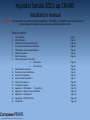
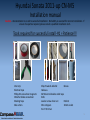
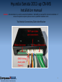
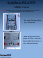
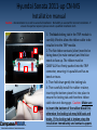
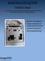
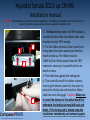
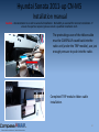
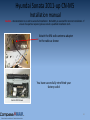
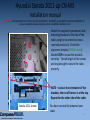
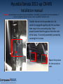
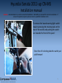
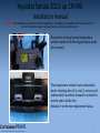
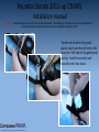
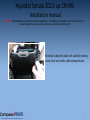
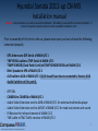
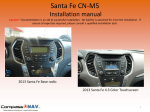
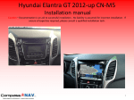
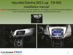
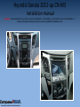
Hyundai Sonata 2011-up CN-M5
Installation manual
Caution – Documentation is an aid to successful installation. No liability is assumed for incorrect installation. If
unsure of expertise required, please consult a qualified installation tech.
1
Hyundai Sonata 2011-up CN-M5
Installation manual
Caution – Documentation is an aid to successful installation. No liability is assumed for incorrect installation. If
unsure of expertise required, please consult a qualified installation tech.
- Follow installation manual instructions carefully. Installer must careful to not cause interference between Navigator System c
abling and active / passive car safety device (Ex: Air bags, seat belts, indicators, etc…)
- Turn OFF the radio.
- Before any attempt of component removal, the installer must disconnect the vehicle battery and isolate the ends of the cable
.
- Do not attempt this installation operation if there are missing components. Please check the bill of materials carefully to ens
ure the kit is complete.
- Installation requires careful attention. If you have concerns about your abilities to perform delicate operations, then do not b
egin the installation.
- The car must be secured to not move during installation. Parking brake must be engaged at all times.
- Operation should be made in a clean, safe and well ventilated environment without trip hazards and slippery floors
- Do not install by yourself if you do not have qualifications and/or tools to perform the retrofit. You may damage the car’s co
mponents and/or the Navigator if not professionally installed.
- Poor installation can result in poor performance, personal injuries and will immediately void the factory warranty.
- Do not install the Navigator in a position that blocks the driver's view or hinders safe vehicle operation.
2
Hyundai Sonata 2011-up CN-M5
Installation manual
Caution – Documentation is an aid to successful installation. No liability is assumed for incorrect installation. If
unsure of expertise required, please consult a qualified installation tech.
Caution
Installation Time is around 3-4 hours with
additional time required for options installation
Do NOT RUSH and if issues occur contact technical support
3
Hyundai Sonata 2011-up CN-M5
Installation manual
Caution – Documentation is an aid to successful installation. No liability is assumed for incorrect installation. If
unsure of expertise required, please consult a qualified installation tech.
Table of contents:
1.
2.
3.
4.
5.
6.
7.
8.
9.
10.
11.
12.
13.
14.
15.
16.
17.
18.
19.
Tools Required –
Bill of Materials –
Cables interconnection identification –
Touchscreen Connections identification –
TRIP Module connection identification –
Vehicle Preparation –
Radio Preparation –
Vehicle Year Specific instructions
a.
2011 Sonata –
b. 2012+ Sonata –
Radio Bracket Installation –
Touchscreen Fascia Installation –
Fascia Trim Preparation –
Lower Console Preparation –
Electrical Connections –
Installation in Vehicle –
Appendix 1 – TRIP Module
Dip Switches
Appendix 2 – Backup Camera Installation
Appendix 3 – Parking Assist
Appendix 4 – RDS Traffic Tuner
Tips & Tricks
Page 5
Page 6
Page 10
Page 16
Page 20
Page 24
Page 35
Page 38
Page 50
Page 63
Page 65
Page 70
Page 77
Page 82
Page 96
Page 110
Page 112
Page 115
Page 118
Page 121
4
Hyundai Sonata 2011-up CN-M5
Installation manual
Caution – Documentation is an aid to successful installation. No liability is assumed for incorrect installation. If
unsure of expertise required, please consult a qualified installation tech.
Tools required for successful install -#1 = Patience!!!
Vice Grip
Electrical tape
Philips #2 screwdriver magnetic
Wide flat blade screwdriver
Masking Tape
Side cutters
Shop Towels & Alcohol
Gloves
Hacksaw
3M Industrial double sided tape
Knife
Jeweler screw driver set
Ratchet
Wire strippers
10mm socket
Torx T15 Driver
5
Hyundai Sonata 2011-up CN-M5
Installation manual
Caution – Documentation is an aid to successful installation. No liability is assumed for incorrect installation. If
unsure of expertise required, please consult a qualified installation tech.
Bill of materials
Aux
cable
Keypad
Cable (Preinstalled)
Audio Patch
Cord
Main I/O 1
Cable
Main I/O 2
Cable
6
Hyundai Sonata 2011-up CN-M5
Installation manual
Caution – Documentation is an aid to successful installation. No liability is assumed for incorrect installation. If
unsure of expertise required, please consult a qualified installation tech.
Bill of materials
Radio face plate
Sonata 2012
Radio face plate
Sonata 2011
Radio
securing
Brackets
Flat ribbon
rubber block
Mini Speaker
with 1 screw
GPS
antenna
7
Hyundai Sonata 2011-up CN-M5
Installation manual
Caution – Documentation is an aid to successful installation. No liability is assumed for incorrect installation. If
unsure of expertise required, please consult a qualified installation tech.
Bill of materials
Main
Touchscreen
(Pre-installed in
fascia Molding)
Fascia
Molding
SD Card to
USB
adapter
TRIP Module
with 2 screws
Bluetooth antenna preinstalled (Sonata 2011
only)
External USB &
SD Card Box (SD
Card already
inserted)
8
Hyundai Sonata 2011-up CN-M5
Installation manual
Caution – Documentation is an aid to successful installation. No liability is assumed for incorrect installation. If
unsure of expertise required, please consult a qualified installation tech.
Bill of materials
Replacement radio
flat ribbon
(Sonata 2012 + only)
XM radio Antenna
adapter
Clock / Temp Sensor/
Passenger warnings
Module patch cord
TRIP Serial cable
9
Hyundai Sonata 2011-up CN-M5
Installation manual
Caution – Documentation is an aid to successful installation. No liability is assumed for incorrect installation. If
unsure of expertise required, please consult a qualified installation tech.
Section 3
System Cable
Connections and
Identification
10
Hyundai Sonata 2011-up CN-M5
Installation manual
Caution – Documentation is an aid to successful installation. No liability is assumed for incorrect installation. If
unsure of expertise required, please consult a qualified installation tech.
Rear Backup Camera
Cable - Main I/O 1
Backup lamp +12V
from Camera RED wire
Ground
GPS Antenna Connection
– Main I/O 1
11
Hyundai Sonata 2011-up CN-M5
Installation manual
Caution – Documentation is an aid to successful installation. No liability is assumed for incorrect installation. If
unsure of expertise required, please consult a qualified installation tech.
External Speaker
Connection – Main I/O 1
TRIP Serial Cable connection:
- 5 Pin to TRIP Module
- 3 Pin(Yellow, Red and Black) to
MAIN I/O 1 Trip Serial cable
- 2 Pin(Blue and Green) to Audio
Patch Cord
12
Hyundai Sonata 2011-up CN-M5
Installation manual
Caution – Documentation is an aid to successful installation. No liability is assumed for incorrect installation. If
unsure of expertise required, please consult a qualified installation tech.
AUX Cable connection
– Main I/O 1
To Audio Patch cord AUX IN (see next page)
AV In connection –
Main I/O 1 (optional)
Composite & stereo jacks
DVD, Game console etc…
13
Hyundai Sonata 2011-up CN-M5
Installation manual
Caution – Documentation is an aid to successful installation. No liability is assumed for incorrect installation. If
unsure of expertise required, please consult a qualified installation tech.
AUDIO SWITCHER
Audio Patch cord:
- AUX IN (previous page) to Audio Switcher
input jack
- Steering wheel control wires (2 pin from TRIP
SERIAL Cable (P:12).
Temp Sensor Serial MAIN I/O 1 to
CLOCK/TEMP SENSOR/Passenger warnings
Module patch cord (3 pins).
8 pins housing not in use
14
Hyundai Sonata 2011-up CN-M5
Installation manual
Caution – Documentation is an aid to successful installation. No liability is assumed for incorrect installation. If
unsure of expertise required, please consult a qualified installation tech.
AV Out Connection – Main I/O 2
Note: Not required to connect to the device
if AV OUT, IR Remote Control or Traffic tuner
are not used.
Rear seats Entertainment AV OUT jacks
IR Sensor and Remote –
Main I/O 2 (optional)
15
Hyundai Sonata 2011-up CN-M5
Installation manual
Caution – Documentation is an aid to successful installation. No liability is assumed for incorrect installation. If
unsure of expertise required, please consult a qualified installation tech.
Power connector for the CN-M5
Navigator coming from the Audio
Patch cord
16
Hyundai Sonata 2011-up CN-M5
Installation manual
Caution – Documentation is an aid to successful installation. No liability is assumed for incorrect installation. If
unsure of expertise required, please consult a qualified installation tech.
Section 4
Touchscreen Connection
identification
17
Hyundai Sonata 2011-up CN-M5
Installation manual
Caution – Documentation is an aid to successful installation. No liability is assumed for incorrect installation. If
unsure of expertise required, please consult a qualified installation tech.
Not in use
Main I/O 1 Main I/O 2
SD/USB connect
Power Connection
18
Hyundai Sonata 2011-up CN-M5
Installation manual
Caution – Documentation is an aid to successful installation. No liability is assumed for incorrect installation. If
unsure of expertise required, please consult a qualified installation tech.
SD/USB connection
box to SD EXT
connection
SD/USB
Interface
Main I/O Connection #1
19
Hyundai Sonata 2011-up CN-M5
Installation manual
Caution – Documentation is an aid to successful installation. No liability is assumed for incorrect installation. If
unsure of expertise required, please consult a qualified installation tech.
Main I/O Connection #2
20
Hyundai Sonata 2011-up CN-M5
Installation manual
Caution – Documentation is an aid to successful installation. No liability is assumed for incorrect installation. If
unsure of expertise required, please consult a qualified installation tech.
Section 5
Trip Module Connections
and ports identification
21
Hyundai Sonata 2011-up CN-M5
Installation manual
Caution – Documentation is an aid to successful installation. No liability is assumed for incorrect installation. If
unsure of expertise required, please consult a qualified installation tech.
Do not use this picture for DIP switches position
TRIP Module Dip
Switch location – For
Sonata 2011 only.
2012 & + does not use
DIP switches.
Switches are factory
preset but please
refer to the Appendix
1 at page 109 for
correct position.
TRIP Module interface
connections
22
Hyundai Sonata 2011-up CN-M5
Installation manual
Caution – Documentation is an aid to successful installation. No liability is assumed for incorrect installation. If
unsure of expertise required, please consult a qualified installation tech.
Trip Module Connections/Cable identification
TRIP 5 pins Cable
wire connections
Ribbon Connector
Keypad Connection
OBDII Parking
Assist cable
(Option)
23
Hyundai Sonata 2011-up CN-M5
Installation manual
Caution – Documentation is an aid to successful installation. No liability is assumed for incorrect installation. If
unsure of expertise required, please consult a qualified installation tech.
TRIP module schematic connections
OBD Parking Assist
connector (option)
CN-M5 Screen
TRIP 3 pins Serial
connector
Flat Ribbon
Cable
I/O Keypad cable
Steering wheel wires
From Audio patch cord
24
Hyundai Sonata 2011-up CN-M5
Installation manual
Caution – Documentation is an aid to successful installation. No liability is assumed for incorrect installation. If
unsure of expertise required, please consult a qualified installation tech.
Section 6
Vehicle Preparation
25
Hyundai Sonata 2011-up CN-M5
Installation manual
Caution – Documentation is an aid to successful installation. No liability is assumed for incorrect installation. If
unsure of expertise required, please consult a qualified installation tech.
Identify the molding to be removed.
Protect the area with masking tape if
needed. Carefully pry away the trim piece
straight up starting at the back of the trim
to gain enough to begin removing by hand.
Insert a protected flat screw driver blade
between the trim and the console where
you see a small gap and pry upwards
When removing the trim piece it needs
to be lifted vertically and pivot slightly
to avoid damage. Do not force it, just
carefully ease it.
26
Hyundai Sonata 2011-up CN-M5
Installation manual
Caution – Documentation is an aid to successful installation. No liability is assumed for incorrect installation. If
unsure of expertise required, please consult a qualified installation tech.
Store these trim pieces carefully to avoid
damage. Repeat the process for the other
side.
Once both trim pieces are removed , the
facia securing screws are exposed.
Remove both screws and reserve.
27
Hyundai Sonata 2011-up CN-M5
Installation manual
Caution – Documentation is an aid to successful installation. No liability is assumed for incorrect installation. If
unsure of expertise required, please consult a qualified installation tech.
Gently pry the black fascia that surrounds
radio starting at the bottom ON BOTH
SIDES where you just removed the screws.
Gently unclip the surrounding towards to
the top of the trim. Be careful to protect
the surrounding dash trim.
Continue with fascia removal by gently
prying the other side to free the panel
from its retaining clips. Do not pull too
far forward. Just enough to disengage
the clips.
28
Hyundai Sonata 2011-up CN-M5
Installation manual
Caution – Documentation is an aid to successful installation. No liability is assumed for incorrect installation. If
unsure of expertise required, please consult a qualified installation tech.
As you gently pull the panel forward
disconnect the multi-way connector
for the clock and airbag warning
light located at the top of the trim.
Once the clock connector is
disconnected pull the fascia further
forward and disconnect the heater
controls multi-way connectors (2).
On vehicle with auto climate control
gently pull the sensor tube off the
the rear of the control. Do the same
for the Hazard switch.
29
Hyundai Sonata 2011-up CN-M5
Installation manual
Caution – Documentation is an aid to successful installation. No liability is assumed for incorrect installation. If
unsure of expertise required, please consult a qualified installation tech.
Undo the 4 securing screws for the radio and
store them safely.
Gently ease the radio forward and
disconnect the FM and XM antenna and
ground cable from the rear of the radio.
Caution, press the locking tab after the
pink plastic to disengage the XM
antenna. A little flat screw driver may
help.
30
Hyundai Sonata 2011-up CN-M5
Installation manual
Caution – Documentation is an aid to successful installation. No liability is assumed for incorrect installation. If
unsure of expertise required, please consult a qualified installation tech.
To free the radio
completely disconnect
the 2 multi-way
connectors on the rear of
the radio. Pressing the
locking tab allows the
connectors to be
removed from the back.
31
Hyundai Sonata 2011-up CN-M5
Installation manual
Caution – Documentation is an aid to successful installation. No liability is assumed for incorrect installation. If
unsure of expertise required, please consult a qualified installation tech.
Next step is to remove the storage
pocket. Remove the 4 retaining screws
for the storage pocket.
Please ensure that you locate the 2
lower difficult screws, save for
reinstallation.
32
Hyundai Sonata 2011-up CN-M5
Installation manual
Caution – Documentation is an aid to successful installation. No liability is assumed for incorrect installation. If
unsure of expertise required, please consult a qualified installation tech.
For Vehicles with BlueLink
Please remove the 6 screws
attaching the BlueLink module to the
support bracket to allow for
clearance to cut the radio support
bracket
Once free, remove the silver brackets
using a T15 Torx driver removing the
4 screws. These parts are not
reused.
33
Hyundai Sonata 2011-up CN-M5
Installation manual
Caution – Documentation is an aid to successful installation. No liability is assumed for incorrect installation. If
unsure of expertise required, please consult a qualified installation tech.
The red arrows indicate the direction
of cut and the area that needs to be
trimmed. The factory radio will be
located deeper in the dash than before
to accommodate the new touchscreen
and bezel mount.
Be careful to not cut electrical wires
Follow the arrows direction of cut!!!!
Using a small saw (or any appropriate
tool) trim the area marked to reflect
the next step. This is necessary to
allow the updated radio to be installed
correctly. Clean the entire area with a
vacuum to remove the plastic debris.
Remove the 10mm nut that holds the
trimmed piece.
34
Hyundai Sonata 2011-up CN-M5
Installation manual
Caution – Documentation is an aid to successful installation. No liability is assumed for incorrect installation. If
unsure of expertise required, please consult a qualified installation tech.
Pry off the plastic antenna cables
support with the help of a flat screw
driver.
Use Vise grips carefully work the
metal stud (circled) back and forth
until it snaps off. Do the same with
the metal support at the left. The
metal support has to be removed
completely at the welding point.
AFTER
35
Hyundai Sonata 2011-up CN-M5
Installation manual
Caution – Documentation is an aid to successful installation. No liability is assumed for incorrect installation. If
unsure of expertise required, please consult a qualified installation tech.
Section 7
Radio Preparation
36
Hyundai Sonata 2011-up CN-M5
Installation manual
Caution – Documentation is an aid to successful installation. No liability is assumed for incorrect installation. If
unsure of expertise required, please consult a qualified installation tech.
Remove existing radio back support
using a Vise grip by unscrewing it
counter clockwise.
Remove existing retaining brackets
using a Phillips head screwdriver.
Secure the 6 countersink screws
removed to be reused later.
37
Hyundai Sonata 2011-up CN-M5
Installation manual
Caution – Documentation is an aid to successful installation. No liability is assumed for incorrect installation. If
unsure of expertise required, please consult a qualified installation tech.
Radio Preparation
Remove the front panel retaining screw as
shown. Repeat for the other side of the
radio.
To detach the front panel completely from
the radio, there are 6 retaining tabs that
retain the radio panel in ( 2 on bottom, 2
on top and 1 either side) . GENTLY lift
these up a little (DO NOT SNAP THEM OFF)
and pry the radio fascia clear enough to
allow access to the cables on the rear.
38
Hyundai Sonata 2011-up CN-M5
Installation manual
Caution – Documentation is an aid to successful installation. No liability is assumed for incorrect installation. If
unsure of expertise required, please consult a qualified installation tech.
Section 8
Vehicle Specific
2011 Sonata continue to next page.
2012+ Sonata jump to page 51
39
Hyundai Sonata 2011-up CN-M5
Installation manual
Caution – Documentation is an aid to successful installation. No liability is assumed for incorrect installation. If
unsure of expertise required, please consult a qualified installation tech.
Once the panel is free of the chassis,
we need to remove the ribbon cable
and the wireless antenna cable.
Notice the ribbon cable connection.
There are locking tab cutouts on the
ribbon cable to ensure the cable stays
in place.
40
Hyundai Sonata 2011-up CN-M5
Installation manual
Caution – Documentation is an aid to successful installation. No liability is assumed for incorrect installation. If
unsure of expertise required, please consult a qualified installation tech.
A little pressure is needed from a
screwdriver to lift up the brown locking tab
to allow the ribbon to freely be
disconnected. Be gentle to avoid
damaging the brown locking tab
Notice the red circles. The ribbon needs to
be disengaged from the unlocked brown
locking tab, to free it from the beige
connector. Separate the white end from
the lock by lifting gently. DO NOT PULL
HARD
41
Hyundai Sonata 2011-up CN-M5
Installation manual
Caution – Documentation is an aid to successful installation. No liability is assumed for incorrect installation. If
unsure of expertise required, please consult a qualified installation tech.
Once the ribbon disengages from the
brown locking tabs gently remove the
ribbon cable from the beige connector
Ribbon Cable disconnected – AT LAST!
42
Hyundai Sonata 2011-up CN-M5
Installation manual
Caution – Documentation is an aid to successful installation. No liability is assumed for incorrect installation. If
unsure of expertise required, please consult a qualified installation tech.
Disconnection of the wireless antenna is
two handed process. There is a locking
ring very close to the PCB (Printed Circuit
Board) that needs to be disengaged (pulled
up slightly) before pulling cable off the
PCB. The cable and connector are very
fragile.
Gently remove the Bluetooth antenna
cable from the circuit board to allow
complete removal.
43
Hyundai Sonata 2011-up CN-M5
Installation manual
Caution – Documentation is an aid to successful installation. No liability is assumed for incorrect installation. If
unsure of expertise required, please consult a qualified installation tech.
After removal of the top screws the top
panel is slid off the radio.
The front securing plate of the radio is
mounted with a total of 7 screws. Two of
these are hidden inside the top cover – as
shown. Remove and store these.
44
Hyundai Sonata 2011-up CN-M5
Installation manual
Caution – Documentation is an aid to successful installation. No liability is assumed for incorrect installation. If
unsure of expertise required, please consult a qualified installation tech.
The front plate needs to be removed from
the radio to allow the assembly of the
new face place provided with the kit.
Remove the 5 retaining screws indicated
and save for later use.
Install the TRIP interface module into the
provided plate in the orientation shown.
(White connector exposed on front of
plate oriented away form CD tray, dip
switches at rear)
45
Hyundai Sonata 2011-up CN-M5
Installation manual
Caution – Documentation is an aid to successful installation. No liability is assumed for incorrect installation. If
unsure of expertise required, please consult a qualified installation tech.
Secure TRIP interface module onto the
bracket using the two philips screws
provided.
DIP switches are factory set, do not
change
46
Hyundai Sonata 2011-up CN-M5
Installation manual
Caution – Documentation is an aid to successful installation. No liability is assumed for incorrect installation. If
unsure of expertise required, please consult a qualified installation tech.
Gently feed the radio ribbon cable and
Bluetooth antenna through the plate and
locate the plate into the front of the radio.
Be cautious to avoid causing any internal
damage as the TRIP interface is pushed into
the radio unit. CAUTION Sometimes the TRIP
might snag a little on connectors, carefully
maneuver into position.
Locate the new face plate in position using
the embosses. Put the first 2 screws in
diagonal to make sure the face plate is
square with the radio and then screw the
remaining 5 screws. At this point you can
slide in the top cover and secure with 2
screws.
47
Hyundai Sonata 2011-up CN-M5
Installation manual
Caution – Documentation is an aid to successful installation. No liability is assumed for incorrect installation. If
unsure of expertise required, please consult a qualified installation tech.
1
3
2
2
1- The black locking tab in the TRIP module is
carefully lifted to allow the ribbon cable to be
installed into the TRIP module.
2- The flat ribbon contacts (silver) need to be
facing down (to make contact) and the blue
needs to face up. The ribbon must be
CAREFULLY but firmly pushed into the TRIP
connector, ensuring it is parallel and has no
bends or tears.
3- Then fold down gently the locking tab.
4- Then carefully install the rubber retainer,
inserting the bottom piece first into place to
ensure the locking tab and therefore ribbon
cable does not disengage. Caution: Make sure
to insert the bottom of the rubber block first
otherwise the locking tab may fold back and
brake. If the locking tab is broken; stop the
48
installation immediately and contact support.
Hyundai Sonata 2011-up CN-M5
Installation manual
Caution – Documentation is an aid to successful installation. No liability is assumed for incorrect installation. If
unsure of expertise required, please consult a qualified installation tech.
The protruding curve of the ribbon cable
must be CAREFULLY eased back into the
radio unit (under the TRIP module), use just
enough pressure to push into the radio.
Completed TRIP module ribbon cable
installation.
49
Hyundai Sonata 2011-up CN-M5
Installation manual
Caution – Documentation is an aid to successful installation. No liability is assumed for incorrect installation. If
unsure of expertise required, please consult a qualified installation tech.
After Completion of your
Sonata 2011 radio
preparation please jump to
Page 63
50
Hyundai Sonata 2011-up CN-M5
Installation manual
Caution – Documentation is an aid to successful installation. No liability is assumed for incorrect installation. If
unsure of expertise required, please consult a qualified installation tech.
Sonata 2012+ Radio
preparation and TRIP
module installation
51
Hyundai Sonata 2011-up CN-M5
Installation manual
Caution – Documentation is an aid to successful installation. No liability is assumed for incorrect installation. If
unsure of expertise required, please consult a qualified installation tech.
There are 2 versions of radio’s used in the 2012+ model. These are identified by the
color of the connector. Brown or Black.
Both connectors require the supplied ribbon cable but have different methods of
disengaging it.
If you have BROWN connector jump to next slide, if you have BLACK connector
jump to slide 55.
52
Hyundai Sonata 2011-up CN-M5
Installation manual
Caution – Documentation is an aid to successful installation. No liability is assumed for incorrect installation. If
unsure of expertise required, please consult a qualified installation tech.
The cable needs to be disengaged from the
unlocked brown locking tab of the radio
body, to free it from the beige connector.
Lift the brown lever up to unlock the
ribbon. DO NOT PULL HARD, to avoid
damage.
Once the brown lock is disengaged
carefully lift the ribbon cable from the
locking tabs and pull out.
Notice the contacts are facing upwards.
53
Hyundai Sonata 2011-up CN-M5
Installation manual
Caution – Documentation is an aid to successful installation. No liability is assumed for incorrect installation. If
unsure of expertise required, please consult a qualified installation tech.
To install the supplied new ribbon cable.
Insert into the connector fully (contacts
side up above brown locking tab) then
press the locking tab down. Note – A
correctly installed cable has
approximately 2mm of silver contact
exposed. The new ribbon cable does not
have the locking tabs like the one
removed. Jump to page 57.
54
Hyundai Sonata 2011-up CN-M5
Installation manual
Caution – Documentation is an aid to successful installation. No liability is assumed for incorrect installation. If
unsure of expertise required, please consult a qualified installation tech.
Sonata 2012+ Radio
BLACK connector
procedure
55
Hyundai Sonata 2011-up CN-M5
Installation manual
Caution – Documentation is an aid to successful installation. No liability is assumed for incorrect installation. If
unsure of expertise required, please consult a qualified installation tech.
The 2012+ Sonata requires a replacement
ribbon cable to be installed into the radio.
This is supplied in the kit. The locking tab
for the ribbon cable is located facing out
from the radio. With a small flat screw
driver, lift up gently the locking tab, at this
point the flat ribbon can be pulled to the
inside of the radio and successfully
removed.
Note – Silver contacts face down on this
type of connector.
Locking tab in lifted position. Do not
detach the flat ribbon from the factory
face plate because it will not be reused.
56
Hyundai Sonata 2011-up CN-M5
Installation manual
Caution – Documentation is an aid to successful installation. No liability is assumed for incorrect installation. If
unsure of expertise required, please consult a qualified installation tech.
Carefully push the replacement ribbon
cable into the connector in the orientation
shown and then lock down the tab to
secure it in place. To ensure the ribbon is
properly inserted, the blue section if the
ribbon should stick out about 1/8” or 3mm
from the connector.
57
Hyundai Sonata 2011-up CN-M5
Installation manual
Caution – Documentation is an aid to successful installation. No liability is assumed for incorrect installation. If
unsure of expertise required, please consult a qualified installation tech.
Remove the 2 screws holding the
CD player as indicated here and
save these separately because they
are smaller. Then remove the 5
screw surrounding the face plate
58
Hyundai Sonata 2011-up CN-M5
Installation manual
Caution – Documentation is an aid to successful installation. No liability is assumed for incorrect installation. If
unsure of expertise required, please consult a qualified installation tech.
Assemble the trip module with the
supplied screws as indicated. The
connector must face the face plate with
the flat ribbon connector located at the
left
TRIP module correctly installed
59
Hyundai Sonata 2011-up CN-M5
Installation manual
Caution – Documentation is an aid to successful installation. No liability is assumed for incorrect installation. If
unsure of expertise required, please consult a qualified installation tech.
Run the flat ribbon thru the new
face plate carefully. Make sure to
not bend the flat ribbon.
Then assemble the new face plate
and locate it using the embosses
circled. Screw the face plate (3
screws) starting by the opposite
corners to make sure the radio
body is square.
Screw the CD player in place using
the bottom holes with the small
screws reserved separately.
60
Hyundai Sonata 2011-up CN-M5
Installation manual
Caution – Documentation is an aid to successful installation. No liability is assumed for incorrect installation. If
unsure of expertise required, please consult a qualified installation tech.
1
3
2
2
1- The black locking tab in the TRIP module is
carefully lifted to allow the ribbon cable to be
installed into the TRIP module.
2- The flat ribbon contacts (silver) need to be
facing down (to make contact) and the blue
needs to face up. The ribbon must be
CAREFULLY but firmly pushed into the TRIP
connector, ensuring it is parallel and has no
bends or tears.
3- Then fold down gently the locking tab.
4- Then carefully install the rubber retainer,
inserting the bottom piece first into place to
ensure the locking tab and therefore ribbon
cable does not disengage. Caution: Make sure
to insert the bottom of the rubber block first
otherwise the locking tab may fold back and
brake. If the locking tab is broken; stop the
61
installation immediately and contact support.
Hyundai Sonata 2011-up CN-M5
Installation manual
Caution – Documentation is an aid to successful installation. No liability is assumed for incorrect installation. If
unsure of expertise required, please consult a qualified installation tech.
The protruding curve of the ribbon cable
must be CAREFULLY eased back into the
radio unit (under the TRIP module), use just
enough pressure to push into the radio.
Completed TRIP module ribbon cable
installation.
62
Hyundai Sonata 2011-up CN-M5
Installation manual
Caution – Documentation is an aid to successful installation. No liability is assumed for incorrect installation. If
unsure of expertise required, please consult a qualified installation tech.
Attach the XM radio antenna adapter
to the radio as shown
You have successfully retrofitted your
factory radio!
Sonata 2012 shown
63
Hyundai Sonata 2011-up CN-M5
Installation manual
Caution – Documentation is an aid to successful installation. No liability is assumed for incorrect installation. If
unsure of expertise required, please consult a qualified installation tech.
Section 9
Radio Bracket installation
64
Hyundai Sonata 2011-up CN-M5
Installation manual
Caution – Documentation is an aid to successful installation. No liability is assumed for incorrect installation. If
unsure of expertise required, please consult a qualified installation tech.
Attach the supplied replacement dash
mounting brackets to the side of the
radio using the countersink screws
reserved previously. Check the
alignment dimples (GREEN circles)
labeled CDP to locate the brackets
correctly Thread length of the screws
are long enough to secure the radio
properly.
NOTE – Look at the orientation of the
brackets, the cut off corner is at the top.
Repeat for the other side of the radio.
Sonata 2011 shown
You have successfully prepared your
radio.
65
Hyundai Sonata 2011-up CN-M5
Installation manual
Caution – Documentation is an aid to successful installation. No liability is assumed for incorrect installation. If
unsure of expertise required, please consult a qualified installation tech.
Section 10
Display Installation into
Fascia
(If the screen has been pre installed into the fascia trim, please skip this section)
66
Hyundai Sonata 2011-up CN-M5
Installation manual
Caution – Documentation is an aid to successful installation. No liability is assumed for incorrect installation. If
unsure of expertise required, please consult a qualified installation tech.
Prepare the display for mounting into the
new supplied fascia (if this was not
completed already). Snug the screws up but
do not tighten to allow for display
adjustment once installed into fascia.
Install the display unit into the fascia. Take
time to ensure that the alignment is correct
by viewing the outside. Look to ensure the
display is square and level. Tighten the
fascia mounting screws to fix the display in
that position.
67
Hyundai Sonata 2011-up CN-M5
Installation manual
Caution – Documentation is an aid to successful installation. No liability is assumed for incorrect installation. If
unsure of expertise required, please consult a qualified installation tech.
Apply LIGHT pressure to the back of the
display to reduce any gaps between fascia
and the display and then tighten the side
screws. Check alignment and make minor
adjustments as necessary.
The screen is preassembled from factory
68
Hyundai Sonata 2011-up CN-M5
Installation manual
Caution – Documentation is an aid to successful installation. No liability is assumed for incorrect installation. If
unsure of expertise required, please consult a qualified installation tech.
Front of keypad
On rear of keypad install the control
cable for connection to TRIP
module.
69
Hyundai Sonata 2011-up CN-M5
Installation manual
Caution – Documentation is an aid to successful installation. No liability is assumed for incorrect installation. If
unsure of expertise required, please consult a qualified installation tech.
Touchscreen panel installed into
replacement fascia. Recheck all screws,
alignments and connections.
70
Hyundai Sonata 2011-up CN-M5
Installation manual
Caution – Documentation is an aid to successful installation. No liability is assumed for incorrect installation. If
unsure of expertise required, please consult a qualified installation tech.
Section 11
Fascia Trim Preparation
71
Hyundai Sonata 2011-up CN-M5
Installation manual
Caution – Documentation is an aid to successful installation. No liability is assumed for incorrect installation. If
unsure of expertise required, please consult a qualified installation tech.
To prepare the new fascia for installation
some components from the old factory
one need to be removed.
Remove the 4 screws holding the clock
module and unsnap it from the fascia.
Reserve for the final assembly.
72
Hyundai Sonata 2011-up CN-M5
Installation manual
Caution – Documentation is an aid to successful installation. No liability is assumed for incorrect installation. If
unsure of expertise required, please consult a qualified installation tech.
To remove the each air vent requires the
removal of 4 silver Phillips screws per vent.
Release the 2 plastic
clips on the outside
of the vent and 1 on
the inside of the vent
that retain the air
vent to the factory
fascia and carefully
remove them.
73
Hyundai Sonata 2011-up CN-M5
Installation manual
Caution – Documentation is an aid to successful installation. No liability is assumed for incorrect installation. If
unsure of expertise required, please consult a qualified installation tech.
Transfer the vent to the provided trim. Be
careful to engage the guiding clip first as shown
then snap in the surrounding clips. Once
properly seated look for gaps on the other side
of the fascia. If correctly assembled, proceed by
screwing the 4 screws.
Repeat the process
for the second air
vent.
74
Hyundai Sonata 2011-up CN-M5
Installation manual
Caution – Documentation is an aid to successful installation. No liability is assumed for incorrect installation. If
unsure of expertise required, please consult a qualified installation tech.
To remove the hazard warning light switch
requires pressing the retaining tabs on the
rear of the switch and pushing the switch
out towards the front of the panel
Once free of its locking tabs the switch just
pulls forward
75
Hyundai Sonata 2011-up CN-M5
Installation manual
Caution – Documentation is an aid to successful installation. No liability is assumed for incorrect installation. If
unsure of expertise required, please consult a qualified installation tech.
Remove the existing factory temperature
control module from the original fascia (undo
the 4 screws)
The temperature module is also retained by
plastic retaining clips (3 in total, 2 on top and 1
underneath) Ease these forward to unlock the
control and it will be free.
Relocate it to the new replacement fascia.
76
Hyundai Sonata 2011-up CN-M5
Installation manual
Caution – Documentation is an aid to successful installation. No liability is assumed for incorrect installation. If
unsure of expertise required, please consult a qualified installation tech.
Transfer the 6 white (or green)
plastic clips from the old trim to the
new trim. Pull side of clip gently and
pull up. Install in carefully and
securely onto new fascia.
77
Hyundai Sonata 2011-up CN-M5
Installation manual
Caution – Documentation is an aid to successful installation. No liability is assumed for incorrect installation. If
unsure of expertise required, please consult a qualified installation tech.
Section 12
Lower Console
Preparation
78
Hyundai Sonata 2011-up CN-M5
Installation manual
Caution – Documentation is an aid to successful installation. No liability is assumed for incorrect installation. If
unsure of expertise required, please consult a qualified installation tech.
The lower storage cubby requires a little
modification for the installation of the SD/USB
interface box.
Unscrew the 4 screws indicated then
unsnap the cover of the lower box
79
Hyundai Sonata 2011-up CN-M5
Installation manual
Caution – Documentation is an aid to successful installation. No liability is assumed for incorrect installation. If
unsure of expertise required, please consult a qualified installation tech.
The lower storage cubby requires a little
modification for the installation of the SD/USB
interface box. An area of plastic needs to be
removed to allow the cable to exit the inside of
the storage cubby.
After placing SD/USB interface box inside
storage cubby, bring cable out of the rear to
allow for connection later. Put back the top
cover and 4 screws.
80
Hyundai Sonata 2011-up CN-M5
Installation manual
Caution – Documentation is an aid to successful installation. No liability is assumed for incorrect installation. If
unsure of expertise required, please consult a qualified installation tech.
Attach the SD/USB adaptor using 3M tape to
the upper underside of the storage cubby.
Once completed the storage cubby looks like this
with the SD/USB interface box installed.
81
Hyundai Sonata 2011-up CN-M5
Installation manual
Caution – Documentation is an aid to successful installation. No liability is assumed for incorrect installation. If
unsure of expertise required, please consult a qualified installation tech.
Reinstall cubby into dash unit carefully routing
wires from rear to the radio compartment.
82
Hyundai Sonata 2011-up CN-M5
Installation manual
Caution – Documentation is an aid to successful installation. No liability is assumed for incorrect installation. If
unsure of expertise required, please consult a qualified installation tech.
Section 13
Electrical/Wiring
Connections
83
Hyundai Sonata 2011-up CN-M5
Installation manual
Caution – Documentation is an aid to successful installation. No liability is assumed for incorrect installation. If
unsure of expertise required, please consult a qualified installation tech.
In the following section we will:
- Prepare the radio patch cable and attach to the car & radio connectors
- Attach the clock / temp patch cable to the car harness and clock module
- Secure the clock module underneath the radio
- Video Tutorial about this section:
https://dl.dropboxusercontent.com/u/70065767/Manuals/Audio%20Patch%20Cord%20Assy.m2ts
Aux
cable
Audio Patch
Cord
Factory Clock module
TRIP Serial
cable
Clock / Temp Sensor/
Passenger warnings
Module patch cord
84
Hyundai Sonata 2011-up CN-M5
Installation manual
Caution – Documentation is an aid to successful installation. No liability is assumed for incorrect installation. If
unsure of expertise required, please consult a qualified installation tech.
Attach the TRIP Serial
cable 2 Pin connector to
this connector to the
Audio Patch cord as
shown.
TRIP Serial cable
85
Hyundai Sonata 2011-up CN-M5
Installation manual
Caution – Documentation is an aid to successful installation. No liability is assumed for incorrect installation. If
unsure of expertise required, please consult a qualified installation tech.
Attach the AUX cable male
jack into the female of the
Aux switcher board as
shown. Secure in place
with Electrical tape.
Reserve the White and
RED RCA jack to be
connected into the AUX
cable from the MAIN I/O 1
Aux
cable
86
Hyundai Sonata 2011-up CN-M5
Installation manual
Caution – Documentation is an aid to successful installation. No liability is assumed for incorrect installation. If
unsure of expertise required, please consult a qualified installation tech.
Connect the Audio Patch
cord to the car matching
connector as shown.
Connectors improperly
seated.
Connectors properly
seated. You should hear a
CLICK.
87
Hyundai Sonata 2011-up CN-M5
Installation manual
Caution – Documentation is an aid to successful installation. No liability is assumed for incorrect installation. If
unsure of expertise required, please consult a qualified installation tech.
Reserve the CN-M5 4
pins square connector
for the final assembly.
Attach the TRIP SERIAL
to the MAIN I/O 1 TRIP
SERIAL. (Ref: P:12)
Reserve the TRIP MOD
cable for the final
assembly. It will be
plugged in front of the
trip module (Ref: P:12)
88
Hyundai Sonata 2011-up CN-M5
Installation manual
Caution – Documentation is an aid to successful installation. No liability is assumed for incorrect installation. If
unsure of expertise required, please consult a qualified installation tech.
This is Patch cord for the clock
/Airbag/Seat Belt/Temp Sensor
module
Plug into the car’s 16 pins
harness as shown at page 93.
Connector for the relocated
Airbag / Seatbelt lights Page 94.
Reserve for the final assembly.
Connect the TEMP SENSOR cable
of the MAIN I/O 1 into the 3 pins
socket. Reserve for the final
assembly.
Plug into the factory Clock /
Temp module (next page)
89
Hyundai Sonata 2011-up CN-M5
Installation manual
Caution – Documentation is an aid to successful installation. No liability is assumed for incorrect installation. If
unsure of expertise required, please consult a qualified installation tech.
Take the protective bag that
your system came in. Cut
enough material to wrap the
module completely.
Once wrapped, cut out the wrapping
around the connector
90
Hyundai Sonata 2011-up CN-M5
Installation manual
Caution – Documentation is an aid to successful installation. No liability is assumed for incorrect installation. If
unsure of expertise required, please consult a qualified installation tech.
Clock Module Patch cord
connected
91
Hyundai Sonata 2011-up CN-M5
Installation manual
Caution – Documentation is an aid to successful installation. No liability is assumed for incorrect installation. If
unsure of expertise required, please consult a qualified installation tech.
Run the clock module cable 16 pin
above and behind the metal tube
Bring the cable down
92
Hyundai Sonata 2011-up CN-M5
Installation manual
Caution – Documentation is an aid to successful installation. No liability is assumed for incorrect installation. If
unsure of expertise required, please consult a qualified installation tech.
Plug in the 16 pins clock module
patch cord into the car harness.
Unplug and look for bent pins, if
pins are bent, straighten back in
position and plug / unplug /
check again by caution.
Secure the clock module with
electric tape with the other
cables sitting at the bottom of
the radio compartment
93
Hyundai Sonata 2011-up CN-M5
Installation manual
Caution – Documentation is an aid to successful installation. No liability is assumed for incorrect installation. If
unsure of expertise required, please consult a qualified installation tech.
Reserve the Airbag / Seat Belt
cable for final assembly. The
cable connects at the back of
the facia under the keypad
board
94
Hyundai Sonata 2011-up CN-M5
Installation manual
Caution – Documentation is an aid to successful installation. No liability is assumed for incorrect installation. If
unsure of expertise required, please consult a qualified installation tech.
Mini speaker installation
Air vent support
Air vent
Driver side kick near gas
pedal
The recommended placement of
the mini-speaker is located on the
driver side. Follow up the side kick
near the gas pedal, locate the
plastic support in front of the feet
air vent. Using the provided
screw, attach the mini –speaker to
the support bracket. The speaker
is very light and require only one
screw. Once completed, bring the
wire to the head unit for final
install.
95
Hyundai Sonata 2011-up CN-M5
Installation manual
Caution – Documentation is an aid to successful installation. No liability is assumed for incorrect installation. If
unsure of expertise required, please consult a qualified installation tech.
Section 14
Installation into Vehicle
96
Hyundai Sonata 2011-up CN-M5
Installation manual
Caution – Documentation is an aid to successful installation. No liability is assumed for incorrect installation. If
unsure of expertise required, please consult a qualified installation tech.
Approximate location of GPS antenna
under the dashboard
Using 3M double sided tape attach the
GPS antenna between the insulation
material and underneath the dashboard.
“GPS” letters of the antenna should be
towards the sky.
Testing has shown that signal is very
good at this point. Route the GPS cable
over the right air duct .
97
Hyundai Sonata 2011-up CN-M5
Installation manual
Caution – Documentation is an aid to successful installation. No liability is assumed for incorrect installation. If
unsure of expertise required, please consult a qualified installation tech.
IMPORTANT
Before proceeding to the final installation if you have
purchased the following options, please proceed to their
installation before completing the final assembly.
- Backup Camera
- Parking Assist System
- RDS Traffic Tuner
Appendix 2 page 112
Appendix 3 page 115
Appendix 4 page 118
98
Hyundai Sonata 2011-up CN-M5
Installation manual
Caution – Documentation is an aid to successful installation. No liability is assumed for incorrect installation. If
unsure of expertise required, please consult a qualified installation tech.
For vehicles with BlueLink
Affix double sided tape and orient the
swivel antenna’s such that they are flat
and once attached to the top the radio
they must face right.
Temporarily support the BlueLink module
underneath the dash board surface with
the communication cable going to the
left and ensuring the swivel antenna
cables point right and are flat. This
allows for clearance behind the radio.
The Bluelink module will be affix on top
of the radio when the radio body will be
in place.
99
Hyundai Sonata 2011-up CN-M5
Installation manual
Caution – Documentation is an aid to successful installation. No liability is assumed for incorrect installation. If
unsure of expertise required, please consult a qualified installation tech.
Once radio is placed in
position affix the Bluelink
module (using the double
sided tape) to the top of
the radio about ¼” back
from the front of the
radio.
100
Hyundai Sonata 2011-up CN-M5
Installation manual
Caution – Documentation is an aid to successful installation. No liability is assumed for incorrect installation. If
unsure of expertise required, please consult a qualified installation tech.
Prior to assembly of the trim to the car, please make sure you have at least the following
connected properly .
-
GPS Antenna to GPS Serial of MAIN I/O 1
TRIP SERIAL cable to TRIP Serial of MAIN I/O 1
TEMP SENSOR (Clock Patch Cord) to TEMP SENSOR SERIAL of MAIN I/O 1
Mini Speaker to SPK of MAIN I/O 1
AUX cable to AUX of MAIN I/O 1 (AUX should have been connected to factory AUX
Audio Switcher at this point).
-
OPTION
CAMERA to CAMERA of MAIN I/O 1
Audio Video Extension cord to AVIN of MAIN I/O 1 for external multimedia player
Audio Video Extension cord to AVOUT of MAIN I/O 2 for read seat screen and sound
IR Receiver for Infrared remote of MAIN I/O 2
TMC cable to TMC Traffic receiver of MAIN I/O 2
101
Hyundai Sonata 2011-up CN-M5
Installation manual
Caution – Documentation is an aid to successful installation. No liability is assumed for incorrect installation. If
unsure of expertise required, please consult a qualified installation tech.
After ensuring all cables are correctly
brought through to area beneath radio,
attach:
- FM Radio antenna
- XM antenna
- Ground cable
- Multi-way connectors (2)
- Audio Patch cord goes into the first
spot.
And install radio in dashboard. If the
radio does not fit well in place, make
sure there is no unnecessary cables and
ensure they are well placed under the
radio. You might need to bend the
ground tab (back right) towards the
radio to give more clearance.
Affix using the screws removed earlier.
102
Hyundai Sonata 2011-up CN-M5
Installation manual
Caution – Documentation is an aid to successful installation. No liability is assumed for incorrect installation. If
unsure of expertise required, please consult a qualified installation tech.
Prior installing the fascia, connect the
TRIP cable to the TRIP module as
indicated (5 PINS) and Parking Assist
System cable (3 PINS) if purchased.
Getting ready to attach the new fascia
trim, connect:
- The wireless antenna cable (Sonata
2011 only).
- Keypad green cable to the TRIP
module.
- Air Bag / Seat Belt connector
- External media box (SD Card/USB)
- Main I/O 1
- Main I/O 2 (If needed)
-
Air controls connectors (see next page)
- Hazard switch
- CN-M5 Power (4 PINS square)
103
Hyundai Sonata 2011-up CN-M5
Installation manual
Caution – Documentation is an aid to successful installation. No liability is assumed for incorrect installation. If
unsure of expertise required, please consult a qualified installation tech.
Caution!!!!!
A/C Controls connectors and tube
MUST be UNDER the metal cross
beam shown.
Otherwise A/C system damage
may occur. When putting the
fascia in place, make sure wires
are not squeezed between the A/C
control panel and the metal cross
beam.
104
Hyundai Sonata 2011-up CN-M5
Installation manual
Caution – Documentation is an aid to successful installation. No liability is assumed for incorrect installation. If
unsure of expertise required, please consult a qualified installation tech.
Install the facia temporarily in place and plug back the wires to the battery and test
run the CN-M5 navigator.
Prior final assembly, test the following:
- Radio mode (TRIP): FM, XM, USB, AUX, CD Steering Wheel Controls and Voice
Commands, etc… ALL functions supported by the factory radio.
- Facia keypad
- Navigation: Check for GPS reception (at least configure the basic settings on start-up)
- MP3 Player: See if you can select music from the File folder (refer to User Manual. Connect
a USB thumb drive to the External Media box prior testing)
Once completed, you can proceed with the final
assembly. Screw in place the new trim (2) Put back
the remaining trim pieces.
105
Hyundai Sonata 2011-up CN-M5
Installation manual
Caution – Documentation is an aid to successful installation. No liability is assumed for incorrect installation. If
unsure of expertise required, please consult a qualified installation tech.
For proper radio operation, the correct
car type needs to be selected.
Go into the CN-M5 Setting Panel, Select
TRIP and at the bottom change
accordingly as below.
Failing to do this may result in a
TRIP.DLL FAILED TO LOAD message.
2011 : Sonata – CAR TYPE 15
2012+ : Sonata – CAR TYPE 26
For Sonata 2012+ : Tick both selections as shown
then close
106
Hyundai Sonata 2011-up CN-M5
Installation manual
Caution – Documentation is an aid to successful installation. No liability is assumed for incorrect installation. If
unsure of expertise required, please consult a qualified installation tech.
Place fascia carefully making sure
you’re not pinching or sharp
bending any wires.
Align trim duct vents to the car
one making sure you not remove
the sealing foams then align the
plastic clips to their holes. Press
firmly the trim surrounding to
snap the clips starting from the
top. Then carefully move the next
clips and apply firm pressure.
Make sure the CD slot is properly
aligned with the trim slot and
look for apparent gaps.
107
Hyundai Sonata 2011-up CN-M5
Installation manual
Caution – Documentation is an aid to successful installation. No liability is assumed for incorrect installation. If
unsure of expertise required, please consult a qualified installation tech.
YOU DID IT!
108
Hyundai Sonata 2011-up CN-M5
Installation manual
Caution – Documentation is an aid to successful installation. No liability is assumed for incorrect installation. If
unsure of expertise required, please consult a qualified installation tech.
Page Intentionally Blank
109
Hyundai Sonata 2011-up CN-M5
Installation manual
Caution – Documentation is an aid to successful installation. No liability is assumed for incorrect installation. If
unsure of expertise required, please consult a qualified installation tech.
Appendix 1
TRIP Module DIP
Switches
(Sonata 2011 only)
110
Hyundai Sonata 2011-up CN-M5
Installation manual
Caution – Documentation is an aid to successful installation. No liability is assumed for incorrect installation. If
unsure of expertise required, please consult a qualified installation tech.
Appendix 1 : Trip module DIP switches (Sonata 2011 ONLY)
Please refer to the DIP switches selection
guide located at the back of the TRIP
module for proper operation.
IMPORTANT
DIP switches proper position are show by
the black squares boxes NOT by the white
crossed boxes.
ON 1 2 3 4
Sonata 2011 DIP switches at their correct
positions are show here.
111
Hyundai Sonata 2011-up CN-M5
Installation manual
Caution – Documentation is an aid to successful installation. No liability is assumed for incorrect installation. If
unsure of expertise required, please consult a qualified installation tech.
Appendix 2
Backup Camera
Installation
112
Hyundai Sonata 2011-up CN-M5
Installation manual
Caution – Documentation is an aid to successful installation. No liability is assumed for incorrect installation. If
unsure of expertise required, please consult a qualified installation tech.
Appendix 2: Backup Camera install
Attach the BLACK wire from MAIN I/O 1
“REAR PWR” to the radio front bottom
screw as shown (Ground) .
113
Hyundai Sonata 2011-up CN-M5
Installation manual
Caution – Documentation is an aid to successful installation. No liability is assumed for incorrect installation. If
unsure of expertise required, please consult a qualified installation tech.
Attach the RED wire from MAIN
I/O 1 “REAR PWR” to the backup
camera RED wire.
Plug the back up camera RCA
jack into the same Yellow
Camera jack of MAIN 1/O 1
114
Hyundai Sonata 2011-up CN-M5
Installation manual
Caution – Documentation is an aid to successful installation. No liability is assumed for incorrect installation. If
unsure of expertise required, please consult a qualified installation tech.
Appendix 3
Parking Assist
115
Hyundai Sonata 2011-up CN-M5
Installation manual
Caution – Documentation is an aid to successful installation. No liability is assumed for incorrect installation. If
unsure of expertise required, please consult a qualified installation tech.
Appendix 3: Parking Assist System
Connection of the Parking Assist System is
OBD II Connector very simple.
Insert into the “CAN”
Position
Plug the other end into the Trip Module as
shown
116
Hyundai Sonata 2011-up CN-M5
Installation manual
Caution – Documentation is an aid to successful installation. No liability is assumed for incorrect installation. If
unsure of expertise required, please consult a qualified installation tech.
Plug the Parking Assist connector
into the car’s OBD located right
underneath the driver crash pad
in the middle. Once inserted,
lock it in place by moving the
yellow tab until you hear a
“click”.
Note: Please advise your dealer about this sensor and how to
proceed to remove it.
117
Hyundai Sonata 2011-up CN-M5
Installation manual
Caution – Documentation is an aid to successful installation. No liability is assumed for incorrect installation. If
unsure of expertise required, please consult a qualified installation tech.
Appendix 4
RDS Traffic Tuner
118
Hyundai Sonata 2011-up CN-M5
Installation manual
Caution – Documentation is an aid to successful installation. No liability is assumed for incorrect installation. If
unsure of expertise required, please consult a qualified installation tech.
Connect the female TMC FM adapter to
the car male.
FM RDS TMC
Connect the male TMC FM adapter to
the back of the radio. Reserve the
white connector MAIN I/O 2 for the
final assembly.
119
Hyundai Sonata 2011-up CN-M5
Installation manual
Caution – Documentation is an aid to successful installation. No liability is assumed for incorrect installation. If
unsure of expertise required, please consult a qualified installation tech.
Tips and tricks
To avoid over heating wire and connectors, it is recommended you use soldering acid
Flux. This will greatly improve the quality of the soldering points. Before soldering, dip
Into the acid flux paste the end of the soldering rod and apply a little flux to the wire
section you wish to solder.
120
Hyundai Sonata 2011-up CN-M5
Installation manual
Caution – Documentation is an aid to successful installation. No liability is assumed for incorrect installation. If
unsure of expertise required, please consult a qualified installation tech.
END
121