1
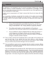
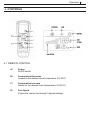
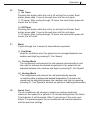
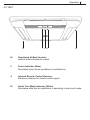
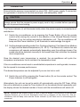
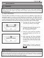
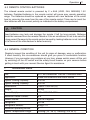
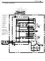
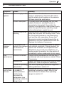
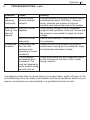
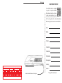
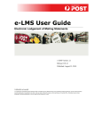
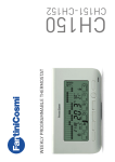
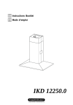
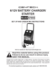
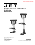
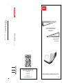
DENSO AUTOMOTIVE SYSTEMS AUSTRALIA PTY LTD
AL00Z00004E
OWNERS MANUAL
Published: October 2012
REV #1: May 2013
Width: 110 mm X Length: 210 mm
Denso
Reply Paid 88460
CROYDON SOUTH VIC 3136
Delivery Address:
2 -46 Merrindale Dr
CROYDON SOUTH VIC 3136
Note: All components must be printed.
The artwork components must not be re-scaled. Re-scaling will create
processing problems.
note:
t is the customer's responsibility to check that the artwork is correct, please check the delivery address details and the addressee details below the barcode. Contact Australia Post if any changes are
required.
Failure to adhere to correct addressing and formatting standards will result in higher customer charges or cancellation of service.
Refer to the Reply Paid Service Guide or visit www.auspost.com.au/replypaid
Please check the artwork details thoroughly. Australia Post is not responsible for any errors.
DENSO AUTOMOTIVE SYSTEMS AUSTRALIA PTY. LTD.
2-46 Merrindale Drive
Croydon Victoria 3136
tel: 03 8761 1449
email: [email protected]
RT1 AIR CONDITIONING UNIT
Operation 1
TABLE OF CONTENTS
1. Foreword
2
2. Inventory
2
3. General Information
3
4. Controls
5
5. Operation
8
6. Maintenance
10
7. Technical Data 11
8. Trouble Shooting
13
© DENSO AUTOMOTIVE SYSTEMS AUSTRALIA PTY. LTD.
May 2013
All rights reserved.
This book may not be reproduced or copied, in whole or in
part, without the written permission of the publisher. DENSO reserves the rights to make changes without
prior notice.
Operation 2
1. FOREWORD
DENSO’s RT1 air-conditioning unit is designed for installation on the roof top of fixed roof
caravans and motor homes. Before using the unit, please take time to read this manual in
detail, and follow the instructions on how to operate this product. Keep this manual in your
caravan, and should you ever decide to sell your caravan, please make sure to pass this
manual on to the next owner.
1.1 DEFINITION OF TERMS
SYMBOLS !
!
MEANINGS
WARNING
Indicates a possibility that “improper handling by the user may result in death or serious injury”.
CAUTION
Indicates a possibility that “improper handling by the user, may result in injury and/or material loss”.
2. INVENTORY
Your air-conditioner unit comprises the following items. 1. External Roof Top unit
3.
2. Air Distribution Unit
Remote Control Unit including a wall bracket and batteries
NOTE: Images not to scale
Operation 3
3. GENERAL INFORMATION
3.1
3.2
The ability of the air-conditioner to maintain a desired temperature depends
upon the heat entering or leaving your vehicle. The following simple guidelines
should be followed to achieve the best comfort, lowest energy use and quietest
operating noise.
a.
Park your vehicle in a shaded area.
b.
Keep all windows, doors, curtain and blinds closed while operating.
c.
Select higher fan speeds for higher cooling performance.
d.
Switch your air-conditioner to cooling early in the day, before the interior
of the vehicle has become too hot.
e.
If the interior of the vehicle is already hotter than the outside air, briefly
open doors and windows to exhaust the hot air before starting the
air-conditioner cooling.
f. Avoid using stoves and ovens that add heat to the vehicle’s interior
while the air-conditioner is cooling.
In humid conditions, the operation of an air-conditioner can cause the formation of
condensate on cold surfaces inside your vehicle. Care must be taken to prevent
this condensate from damaging personal items, or causing a build up of mould. Items that may be damaged by the condensate must be kept clear of the air
distribution unit. In rare circumstances, condensate can form on this unit during
use. Should there be formation of condensate, allow it to dry thoroughly after use.
NOTE: Condensation can be reduced by keeping all doors and windows closed during
air-conditioner operation, preventing humid air from entering the vehicle. The likelihood of
condensation on the air distribution unit can be reduced by ensuring that the caravan is properly
sealed, preventing entry of moisture laden air.
!
WARNING
All electrical work and permanent wiring must be carried out by an appropriately
qualified person in accordance with national wiring regulations and all other applicable
local codes and regulatory authority requirements.
Repair to electrical components by non-certified technicians may result in death,
personal injury and/or damage to the unit. All electrical components replaced must be
genuine replacement parts, purchased from an authorised reseller.
Operation 4
WARNING
!
This appliance is not intended for use by persons (including children) with reduced
physical, sensory or mental capabilities, or lack of experience or knowledge, unless
they are supervised and given instructions concerning the use of the appliance by a
person responsible for their safety.
Children must be supervised at all times to ensure that they do not play with this
appliance.
Prior to operation, familiarise yourself with the location of the safety circuit breaker
and isolation switch for the air-conditioner on your caravan. In the event of a fault
or damage, switch off the power supply, and contact an approved service agent for
assistance.
a.
Only a licenced electrician may replace the unit fuse. The fuse is
located in the electrical control housing inside the roof top unit. Fuse
rating is 250V/500VAC, 10A, T-Delay, 5x20mm supplied by DENSO.
b.
The safety circuit breaker must be switched to ‘off’ position to disconnect it from the power supply before any disassembly or repairs.
c.
The air-conditioner uses the refrigerant R410a under high pressure. It
is both dangerous and illegal to tamper with the sealed refrigerant
system without appropriate licensing. Intentional release of refrigerant is illegal in Australia and New Zealand.
3.3 The air intake, exhaust and condensate drain on the sides of the external unit
must be kept clear of any material that may block airflow or water drainage. Failure to keep these areas clear could cause poor performance, water leakage
into your vehicle and permanent damage to the air-conditioner.
3.4 The air-conditioner must never be operated while the vehicle is moving. Before
operating the air-conditioner, ensure that the vehicle is parked with the unit tilted
no more than 5˚ from the horizontal.
This unit is designed to be operated on 230 - 240V 50Hz power from the electricity
grid or a sine wave inverter equipped generator. The recommended generator
capacity for this unit is 2.4 kVA Continous Power. When choosing a generator,
please bear in mind that other devices and appliances may add to the demand on
the generator. In this case, the generator capacity should be selected accordingly.
Operation 5
4. CONTROLS
4.1 REMOTE CONTROL
A/
Power
On/Off switch
B/
Temperature Decrease
Lowers to the desired room temperature (16-30˚C)
C/
Temperature increase
Raises to the desired room temperature (16-30˚C)
D/
Fan Speed
Cycles the interior fan through 3 speed settings.
Operation 6
E/
Timer
(i) On Timer
Pressing this button while the unit is off will set the on timer. Each button press adds 1 hour to the wait time until the unit starts (1-12 hours). After cycling through 12 hours, the next button press will cancel the ‘on’ timer.
(ii) Off Timer
Pressing this button while the unit is on will set the off timer. Each button press adds 1 hour to the wait time until the unit stops
(1-12 hours). After cycling through 12 hours, the next button press will cancel the ‘off’ timer.
F/ Mode
Cycles through the 3 modes of airconditioner operation.
(i) Fan Mode
Used for ventilation only. Fan speed can be changed between low, medium and high by pressing D- Fan Speed.
(ii) Cooling Mode
The compressor and external fan will operate automatically to cool the cabin to achieve the desired temperature. Fan speed can be adjusted between low, medium and high by pressing D- Fan Speed.
(iii) Heating Mode
The compressor and external fan will automatically operate to heat the cabin to achieve the desired temperature. The interior fan speed can be adjusted between low, medium and high by pressing
pressing D - Fan Speed to achieve an optimum heating performance.
G/ Quick Cool
The air-conditioner will change to maximum cooling mode and maximum fan speed for a period of 15 minutes during which the Quick Cool Indicator K will illuminate. After 15 minutes (or if the quick cool
button G is pressed again) the air-conditioner will resume operation with the previous settings.
Operation 7
4.2 UNIT
H I J K H
H/ Directional Airflow Controls
Vertical airflow directional control.
I/ Power Indicator (Blue)
Illuminates when the air-conditioner is switched on.
J/ Infrared Remote Control Receiver
Electronic receiver for remote control signal.
K/ Quick Cool Mode Indicator (White)
Illuminates while the air-conditioner is operating in quick cool mode.
Operation 8
OPERATION
5.
Ensure that the caravan is connected to a clean 230 - 240V power supply. If connected
to a generator, it must be of the sine-wave type, and adequately rated.
!
CAUTION
Always ensure that the caravan’s power supply cord is fully uncoiled before operating
the unit to prevent overheating.
The Power indicator (I) will illuminate briefly when the power supply is connected and
switched on.
5.1 Switch the air-conditioner on by pressing the Power Button (A) on the remote
control while aiming the control in the direction of the Infrared Remote Control
Receiver (J) on the ceiling mounted air distribution unit. The air-conditioner will
beep and the Power Indicator (I) will illuminate to acknowledge the signal.
5.2 Set the desired operating mode (Fan, Cooling or Heating), Fan Speed (low, Medium
or High) and the desired temperature (16 - 30˚C). The interior fan, exterior fan and
compressor will operate automatically depending upon the settings chosen. Fan
speed should be selected manually to the lowest level that achieves the desired
room temperature.
Once the desired room temperature is reached, the air-conditioner will cycle the
compressor and exterior fan to maintain the temperature level.
If the air-conditioner cannot reach a comfortable temperature in cooling mode, increase
the fan speed to increase performance.
The desired temperature can be adjusted if you are too hot or cold.
5.3 Switch the unit off by pressing the Power button (A) on the remote control. The
Power Indicator (I) will extinguish.
Alternatively, the unit can be set to switch off automatically using the Off Timer. While
the unit is switched on, press the Timer button (E) on the remote control repeatedly until
the display shows the desired number of hours until the airconditioner will switch off.
NOTE: Whenever the remote control is used, it must be aimed in the direction of the Infrared
Remote Receiver (J) on the Air Distribution Unit from a distance of less than 8m. The air
distribution unit will beep once and the Power Indicator (I) will flash once to acknowledge the
command.
Operation 9
The compressor and exterior fan speed are microprocessor controlled to automatically
ensure a long life for your air-conditioner while maintaining the best possible comfort.
Depending upon the conditions and air-conditioner settings, you may notice some of
the following:
a. Automatic Compressor Start Protection: The compressor start may be delayed for up to 3 minutes after selecting cooling or heating mode.
b. Exterior Fan Speed: The exterior fan may switch between high and low speeds to minimize the operating noise of the airconditioner for you and your neighbours.
c. Cooling Operating Range: The compressor may not operate in cooling mode if the outside temperature is greater than 45°C in order to protect the refrigerant system.
d. Heating Operating Range: The airconditioner is designed to operate in heatingmode when the outside temperature is between 0-25°C. If the temperature is outside this range the compressor may not operate in order to protect the refrigerant system.
e. Preheat: The interior fan will not switch on in heating mode until the air- conditioner has warmed up sufficiently to deliver comfortably warm air. At very low temperatures this could take up to 10 minutes from the start of the compressor and exterior fan.
f. De-icing: The air-conditioner operates as a heat pump when in heating mode. Heat is drawn from the outside air to warm the vehicle. As the outside air temperature drops, less heat is available to the air-conditioner and a decrease in the heating performance may be noticed. When the outside temperature is very low (below 8°C) ice may form on the condenser in the air-conditioner. The microprocessor control has a fully automatic protection function that will remove the ice when required. Depending upon the conditions, you may notice the compressor, interior and exterior fans switching
off as often as every 15 minutes to protect your air-conditioner and provide maximum comfort.
Operation 10
MAINTENANCE
6.
!
WARNING
Always ensure that the air-conditioner is isolated from the mains power supply by
switching off the AC switch and safety circuit breaker, before performing and during
any maintenance.
6.1 INLET AIR FILTER
Two dust filters are fitted to the return air inlet of the air-conditioner. These filters are
essential to prevent a build up of dust blocking the evaporator. The filters (Part No.
TA145520-2230) must be cleaned at least twice per year by washing in warm water with
a mild household detergent. Allow the filters to dry, before re-installing. Replacement
filters are available for purchase as spare parts should the original be damaged.
a. Flip down the two tabs on the sides
of the filter, as shown in the image.
b. Flip down the centre tab, and use it to
pull the air filter approximately
20 - 30 mms out of the unit.
c. Once the outer tabs are exposed,
use them to gently pull the filter out
of the unit.
d. After cleaning the filters carefully
insert them back into the slots which
are provided. Once the filter is fully
in place, press down the three tabs
to lock it in.
Repeat steps a, b and c above for
the second filter on the other side of
the unit.
!
CAUTION
Failure to clean the filter will result in decreased air-conditioner performance, increased
noise and possible overheating and damage to the air-conditioner. The air-conditioner
should never be operated without the filters installed.
Operation 11
6.3 REMOTE CONTROL BATTERIES
The infrared remote control is powered by 2 x AAA (LR03, 24A, MN2400) 1.5V
batteries. Depleted batteries in the remote control will cause poor remote operating
range. The batteries should be replaced as required with new batteries of the same
type by removing the cover from the rear of the remote control. Take care to insert the
new batteries with the correct polarity as indicated in the battery compartment.
!
CAUTION
Dead batteries may leak and damage the remote if left for long periods. Batteries
should be removed from the remote if dead or if the air-conditioner is not to be used for
a long period. Damage to the remote control caused by leaking batteries is not included
in the terms of the manufacturer’s defect warranty.
6.4 GENERAL CONDITION
Regularly inspect the condition of the unit for signs of damage, wear or malfunction. If used correctly, this air-conditioner should give you years of comfortable function. However, if you encounter any problems at any time, please switch power off the unit
by switching off the AC switch and the safety circuit breaker on your caravan before
getting in touch with your nearest Service Agent for assistance.
7.
TECHNICAL DATA
Unit:
RT1 Air-Conditioner. Part No. TA448006-9260
Application:
Fixed roof caravans and motor homes
Typical Cooling Capacity:
2.5 kW
Typical Heating Capacity:
2.0 kW
Dimensions:
1096 x 739 x 207(H)
Weight:
39 Kg.
Power Supply:
230 - 240V AC, 50Hz
Maximum Rated Current:
8A
Airflow volume:
340 m³/h approx.
Refrigerant:
R410a
Refrigerant amount:
635g ± 10
Maximum operating incline:
5˚
Typical Temperature Range:
Cooling (16 - 48˚C) Heating (-3 to 25˚C)
Operation 12
BUZZER
QUICK COOL LED
IR RECEIVER
16
POWER LED
7.1 WIRING DIAGRAM
17
1
2
3
4
5
6
7
8
9
10
11
12
13
14
15
16
17
SUPPLY CONNECTION
COMPRESSOR
THERMAL SWITCH
PRESSURE SWITCH
CAPACITOR
PTC STARTER
CAPACITOR
EXTERIOR FAN
CAPACITOR
INTERIOR FAN
CAPACITOR
TRANSFORMER
SOLENOID
MAIN PCB
10A FUSE
REMOTE PCB
REMOTE HARNESS
BROWN
RED
ORANGE
10
11
BLUE
BLUE
13
GREY
GREY
CONNECTION MUST COMPLY
WITH LOCAL LAWS AND
REGULATIONS.
9
GREY
WHITE
BLUE
BROWN
BLACK
1
CONNECTION BY INSTALLER
GREEN/YELLOW
BROWN
GREY
BLACK
WHITE
WHITE
USE ONLY SPECIFIED
REPLACMENT FUSES &
ELECTRICAL COMPONENTS.
A
N
12
BLUE
GREEN/YELLOW
BROWN
BLUE
GREEN/
YELLOW
A
N
15
GREEN/YELLOW
8
3
4
RED
BLUE
RED
BLACK
2
GREEN/YELLOW
14
5
BLACK
6
7
VIOLET
BLACK
Operation 13
8.
TROUBLESHOOTING
Symptom
Cause
Remedy
Unit does not Power supply is off
operate
Check and confirm that the caravan main
power is switched on. Check the AC switch
and the safety circuit breaker on the caravan. All these should be switched on.
Power interruption
To protect itself from damage, the unit may
switch off (return to standby) if power is
momentarily interrupted. Ensure that the
caravan is connected to a clean power supply
within the specified power operating range
before attempting to restart the unit.
Remote control not
working
Remote control instructions are confirmed by a
beep and the power LED blinking once. There
is a short delay between a command being
sent and the unit responding. Ensure that
the remote control is pointed towards the air
distribution unit from a distance less than 8m. Replace the batteries if necessary.
Exterior fan
changes
speed.
The speed of the
exterior fan changes
or switches off
occasionally
The external fan is adjusted based on system
and ambient conditions. Where possible, the
exterior fan will switch to low speed for less
disturbance to you and your neighbours. In
heating mode, the exterior fan may switch off
periodically to allow condensate to drain away
Poor
performance
Blocked condenser
Check that the condenser (on the roof top) is
not blocked with dust, leaves or rubbish. Clean
if neccesary.
Blocked filter
Inspect the indoor air filter on the inner air distribution unit. Clean or replace if necessary.
Outside of operating Use within operating temperature range and
temperature
follow guidelines in section 3.1
Compressor
cuts or does
not start.
The system has
a number of
inbuilt protection
mechanisms
to protect the
compressor from
operating outside its
design limits
Ensure that the unit is being used within it’s
operating temperature range. Refer to the
technical data for details of the operating
ranges in section 3.1.
Operation 14
8.
TROUBLESHOOTING - cont...
Symptom
Cause
Remedy
Unit
operating
continously
System unable
to reach desired
setpoint.
Change temperature setting on remote control
(confirmed by beep & LED blink). Close all
doors, windows and curtains to improve
insulation and reduce the load on the system.
Both LED’s
Both LED’s flash
flashing. Unit together.
does not
operate.
Condensate
formation
Power supply voltage is out of acceptable
range for safe operation of the unit. Ensure that
the caravan is connected to supply of correct
voltage.
Both LED’s flash
alternately.
Internal fault detected. Contact service centre
for assistance.
Condensate may
form on cold
surfaces when
operating in humid
conditions.
Ensure all doors and windows are properly
sealed when running the air-conditioner. Keep
all cupboards and drawers closed.
The evaporator
Check and confirm that the condensate drains
condensate drain
on the roof top unit are clear of dirt or other
is blocked. This
foreign material.
may be indicated by
water droplets being
carried in the air.
If symptoms persist after the above actions have been taken, switch off power to the
air-conditioning unit at the safety circuit breaker and the air-conditioner switch on your
caravan, and contact your nearest dealer or a qualified technician for help.
Operation 15
DENSO WARRANTY
AN IMPORTANT MESSAGE FROM DENSO
Thank you for purchasing a DENSO Product.
To ensure that Your DENSO Product performs properly and to ensure the validity of DENSO’s Warranty, please follow all the
instructions and recommendations concerning the installation, use, servicing, maintenance and repair of the Product, as set
out in the documentation provided with the Product. If You require further assistance concerning the Product after reading all
such instructions and recommendations, please contact Us, using the contact details in clause 3 below. We recommend that You contact Us or an Authorised DENSO Service Representative for all Your service needs.
NOTICE TO CONSUMERS UNDER AUSTRALIAN CONSUMER LAW
The following applies if You are a ‘consumer’ under the Australian Consumer Law:
Our goods come with guarantees that cannot be excluded under the Australian Consumer Law. You
are entitled to a replacement or refund for a major failure and compensation for any other reasonably
foreseeable loss or damage. You are also entitled to have the goods repaired or replaced if the goods
fail to be of acceptable quality and the failure does not amount to a major failure.
The benefits provided by DENSO’s Warranty are in addition to any other rights and remedies of a
consumer under the Australian Consumer Law and any other law which may apply to the Product.
1. WHAT IS COVERED BY THIS WARRANTY?
We warrant that Your DENSO Product purchased in Australia is free from defects in material and workmanship, subject to
the Exclusions set out in clause 7 and the other terms and conditions contained in this document.
2. WARRANTY PERIOD
This Warranty applies to any defect in Your DENSO Product which appears within the period:
(a) commencing on the date the Product was purchased from the Supplier; and
(b) terminating 12 months after commencement.
Any Product We repair or replace under this Warranty will be warranted by Us under this Warranty for the balance of this
Warranty Period only. 3. WHO GIVES THIS WARRANTY?
DENSO Automotive Systems Australia Pty Ltd
2-46 Merrindale Drive
Croydon, Vic, 3136
Technical Service Department:
Tel: 03 8761 1449
Fax: 03 8761 1502
Email: [email protected]
4. WHAT WE WILL DO
To honour this Warranty, We will:
(a) repair or replace the Product, at Our option and expense;
(b) arrange for the Product to be repaired or replaced, at Our option and expense; or
(c) pay You an amount equivalent to the cost of repairing or replacing the Product.
5.WHAT YOU MUST DO
To ensure that You remain entitled to claim under this Warranty, You must:
(a) provide Us with satisfactory proof of purchase of the Product, which clearly indicates the name and address of the Supplier, the date and place of purchase, and identifies the Product (We recommend that You provide Us with a legible and unmodified receipt or sales invoice for the Product);
(b) install, use, service, maintain and repair the Product in accordance with Our instructions and recommendations; and
(c) ensure that none of the Exclusions in clause 7 apply.
6. PROCEDURE TO CLAIM UNDER THIS WARRANTY
To make a claim under this Warranty, You must take the following steps:
STEP 1
Contact Us, during the Warranty Period, using the contact details in clause 3, and provide Us with Your name, address, telephone number, details of the Product, details of the Supplier and an outline of Your claim in relation to the Product. We will direct You to take the product to an Authorised Denso Service Repairer, the Supplier or us.
Operation 16
STEP 2
You must then take the Product to an Authorised Denso Service Repairer, the Supplier or us in accordance with our
directions. You must provide satisfactory proof of purchase.
STEP 3
Following inspection of the Product, You will be informed whether Your claim has been accepted and, if so, whether
the Product will be repaired or replaced at our expense, or whether You will be paid an amount equivalent to the cost of
repairing or replacing the Product.
Neither the Supplier or any Authorised DENSO Service Repairer are authorised to accept Your claim on our behalf, unless
expressly authorised by Us to do so. .
Please note that this Warranty does not cover any expenses You may incur in making a claim under this Warranty,
including any cost of having an Authorised DENSO Service Repairer travel to the premises at which the Product
is located, the cost of removing the Product from its place of installation or reinstalling the Product, and the cost of
transporting the Product for the purposes of repair or replacement.
7. EXCLUSIONS
This Warranty does not apply if the Product is outside Australia or if the claim is wholly or partly attributable to any:
(a) failure to properly install, use, service, maintain and repair the Product, in accordance with any instructions or recommendations from Us;
(b) misuse of the Product including use of the Product for purposes other than its intended purpose, use of the Product contrary to Our instructions and recommendations, and use of the Product after it becomes apparent that it requires service, maintenance or repair;
(c) accidental damage including fire, theft and explosion;
(d) acts of God and damage or corrosion to the Product caused by environmental conditions including excessive moisture, acid rain, airborne fallout, stones, salt, sand, hail, wind, storms, lightning, floods, infestation by rodents or other vermin;
(e) modification of the Product in a manner not authorised by Us;
(f) incorporation of parts other than DENSO parts or other parts authorised by Us;
(g) normal wear and deterioration, having regard to the operating environment of the Product, including discoloration;
(h) routine service or maintenance costs;
(i) components warranted by other manufacturers;
(j) failure to respond in a timely manner to any malfunction of the Product;
(k) non-DENSO product, or any installation, service, maintenance or repair by a person other than an Authorised DENSO Service Repairer or other person approved by Us; or
(l) commercial use of the Product.
8. LIMITATION OF LIABILITY UNDER THIS WARRANTY
As indicated in clause 4, Your rights under this Warranty are limited to repair or replacement of the Product, or being paid the cost of repairing or replacing the Product. We will not be liable under this Warranty for any consequential loss including, without limitation, the injury or death of any person, damage to any other property, or loss of any income, profit or business. 9. EXCLUSION AND LIMITATION OF ANY OTHER LIABILITIES
Except as provided under this Warranty and by law, We give You no warranty, guarantee or similar right in relation to the
Product. To the full extent permitted by law, We exclude any warranty, guarantee or similar right provided or implied by
law. If any warranty, guarantee or similar right provided or implied by law applies to the Product, to the full extent permitted by
law We limit Our liability to You to the repair or replacement of the Product, or the cost of having the Product repaired or
replaced. Except as provided by law (including the Australian Consumer Law, if applicable), We will not be liable to You, whether in
contract, tort or otherwise, for any loss or damage suffered as a result of You acquiring the Product. 10. DEFINITIONS
“Authorised DENSO Service Repairer” means a person or company authorised by Us to provide service for such
Products.
“Product” means [the RT1 caravan air-conditioner unit] supplied with this Warranty in Australia, and used exclusively in
Australia. “Supplier” means the authorised distributor or retailer of the Product who sold You the Product or Us if We sold you the
Product. “Warranty Period” means the period of time defined in clause 2. “We” or “Us” or “Our” means DENSO Automotive Systems Australia Pty Ltd ACN 007 110 929.
“You” or “Your” means the retail purchaser of the Product from the Supplier or the original end-user of the Product.
Operation 17
REGISTRATION OF YOUR UNIT
All electrical work and permanent wiring must be carried out by an
appropriately qualified person in accordance with national wiring regulations
and all other applicable local codes and regulatory authority requirements.
This unit must be earthed & connected through a suitably rated twopole switch allowing disconnection of the active & neutral conductors.
Location of the Serial Number on the roof top unit:
PLEASE REMOVE AND RETURN OWNER’S REGISTRATION CARD WITHIN 30 DAYS OF PURCHASE
Once installed, owners are encouraged
to register their product with DENSO.
Please follow the link, via the QR code to
complete on-line registration or log on
to www.denso.com.au/caravan and look
for the “on-line registration forms - Caravan Airconditioning.”
Alternatively, complete the below form and mail it to DENSO.
Name:
Address:
Telephone:
Caravan brand:
Caravan model:
Date of purchase:
Place of purchase:
Installed by:
Serial No: **
** See page #17 for location of Serial No.