1
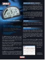
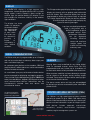
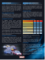
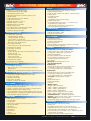
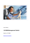
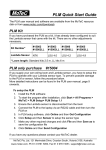
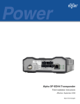
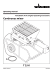
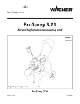
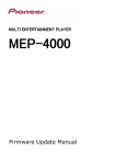
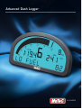
Advanced Dash Logger
in control
ANALOG AND DIGITAL CHANNELS
In total, the ADL can accommodate over 200 channels
derived from a mixture of Analog, Digital, RS232 Serial
and CAN bus data channels. It directly supports up to 28
analog inputs, 12 digital/speed inputs, 8 auxiliary
outputs and 2 high accuracy Wideband Lambda (air/fuel
ratio) inputs.
The analog channels sample at up to 1000 samples per
second per channel, with a measurement range of 0 to
15 VDC, and 12 bit resolution. Digital and Speed inputs
are used for state monitoring, counting and pulse width
measurement. They accept switch, logic, open collector
(Hall Effect), or magnetic signals.
MoTeC ADVANCED DASH LOGGER
•
•
•
•
•
•
•
•
•
•
•
Fully programmable
Up to 8 Mbyte Flash memory
Advanced Control Functions
Support for modems, GSM devices & GPS systems
High Contrast LCD display (backlit display optional)
Sampling rates up to 1000 samples/ second
Over 200 Channels of Analog, Digital & Serial Data
High Speed data downloading
Easy to use 32 bit Windows software
Powerful Analysis Software
32 Bit Microprocessor
The MoTeC Advanced Dash Logger (ADL) is a fully
featured, self contained, programmable data logger,
device controller and display unit. Easy to use 32 bit
software gives the system a flexible interface that allows
it to be adapted to most applications.
Many vehicle, marine and industrial applications require
separate products to perform the logging, controlling and
displaying. However, the MoTeC ADL offers seamless
integration of all three functions.
Most aspects of the ADL are fully configurable - what to
log, what logging rates, which channels to use for display,
warning lights and control outputs.
The MoTeC ADL uses a high speed 32 bit microprocessor and
incorporates a 79 pin autosport connector. The ADL is built to
internationally recognised quality and manufacturing
standards and is backed by a full 2 year worldwide warranty.
OUTPUTS
The auxiliary outputs can be configured to operate as
simple off/on outputs, duty cycle control or frequency
based outputs.
DATA LOGGING
Data logging allows for readings taken from Analog,
Digital, Serial, CAN or Calculated channels to be stored
in the ADL for later analysis on a computer. The ADL
uses non-volatile Flash memory. Data memory may be
retrieved at very high speeds (approximately 19 seconds
per Mbyte). Different logging options allow 384Kbyte,
1Mbyte, 2Mbyte, 4Mbyte or the full 8Mbyte to be
accessed.
The ADL can store samples at up to 1000 per second per
channel, the rate can be individually set for each
channel. Four logging modes may be run concurrently
(Normal, Fastest Lap and two Burst modes), each with
user defined start and stop logging parameters. Memory
can operate in
stack or circular
buffer mode.
User definable graphs
provide analysis of data
from all logged channels.
DISPLAY
The MoTeC ADL display is a high contrast, high
temperature, custom designed reflective LCD. Its unique
design makes it easily viewed in direct sunlight or
artificial light. An optional backlit LCD display is now
also available for maximum visibility in low ambient
light conditions.
The display has three
modes of operation,
where each mode is
fully programmable
and independent
of each other.
Each mode may
be selected by
pressing
a
button,
or
activated by a
user
defined
condition.
The 70 segment bar graph display can be programmed to
display any channel, with an optional peak hold marker
and shift marker. Each numerical display item can be
programmed to display any channel value as required.
The 13 digit alphanumeric display has 20 lines available
to scroll through and may be used to display any
channel or warning messages.
Lap times may be displayed when
used in conjunction with a
MoTeC Lap Beacon (or driver
activated switch). Other
performance information
can
be
displayed,
including: Minimum
corner and maximum
straight speed, fuel
used or fuel remaining
and many more.
SERIAL COMMUNICATIONS
The RS232 serial port is programmable up to 115k baud
and can be used as both a telemetry data output port
and a serial data input port.
As a telemetry port; devices such as modems, GSM and
satellite phones, radio modems etc. can be connected to
facilitate remote connection.
As a serial data input port; serial communication devices
can be connected for displaying and logging purposes.
These include Engine Management Systems (MoTeC and
other), bar code devices, keypads, GPS Systems or other
serial communication devices. Information may be
simultaneously received from one device and
transmitted to another.
ALARMS
Warning alarms may be defined for any analog, digital,
serial or calculated channel. Alarm limits are fully
programmable and may include up to 6 conditions to
ensure that the alarms are only activated at the correct time.
When an alarm condition has been detected, a message
can be shown on the display and an auxiliary output
activated. These outputs can be used for warning lights
or the control of other devices.
The alarms remain active until they are acknowledged
by activating a switch or automatically after a definable
period of time.
CONTROLLER AREA NETWORK (CAN)
The Virtual Instrument Dash
provides a representation of
the data using a gauge format.
The CAN bus is a high speed communication standard
operating at speeds of up to 1Mbit. CAN allows many
devices to be connected by a common bus, allowing all
devices to share information as part of a larger system.
Automatic track maps
with colour gradients
allow for easy analysis.
CAN devices include: automatic transmission
controllers, sensors, multi-channel input/output
modules, engine management systems etc.
www.motec.com.au
HOST SOFTWARE
The ADL is supplied with software packages for managing
the ADL, analysing the logged data and monitoring a
telemetry link. Ease of use is one of the most attractive
aspects of the MoTeC ADL software. There is no complex
language to learn, just simple menu driven windows. A
full online help system is easily accessible and is
integrated throughout the software.
UPGRADES AND ACCESSORIES
The MoTeC ADL is completely field updateable by the user.
The control software and logged data is stored in Flash
memory. No programming interface is required, simply
send the new program to the ADL and the latest features
are immediately available.
UPGRADE OPTIONS
The Dash Manager software is used to configure the ADL
and download logged data. It is logically laid out, giving
the user access to the power of the ADL without requiring
high levels of computer knowledge or intense training.
The MoTeC ADL has field upgradeable options using a
password enabling system. Upgrade options include: 30
and 50 Inputs/Outputs (see table below), Pro Logging,
384Kbyte, 1Mbyte, 2Mbyte, 4Mbyte and 8Mbyte Logging,
Telemetry Support, Remote Logging and Wideband
Lambda measurement.
INTERPRETER SOFTWARE
INPUT/OUTPUT UPGRADES
DASH MANAGER SOFTWARE
The
Interpreter
software
contains
pre-defined
configurations for easy data analysis. Screen display
formats may be varied to suit all preferences, including
user defined graphs, virtual instrument display,
histograms and statistical summaries. By utilising these
different display methods, users can view data in many
formats to obtain accurate, meaningful analysis. Data can
also be exported into ASCII CSV file format for analysis in
other software packages.
The Pro Logging option includes multiple graph overlays,
advanced mathematical functions, XY graphs (scatter
plots), rainbow track maps (shows minimum and
maximum speeds, gear change point and braking points)
and other advanced features.
TELEMETRY MONITOR (OPTIONAL)
The Telemetry Monitor software allows for real time
viewing of the telemetry data either via direct serial
communications, modems or radio modems. Data can
be viewed in various formats such as charts, bar graphs,
dial gauges, numerics, lights, XY graphs and scroll
charts. All objects are definable by the user.
BASIC
30 I/O
50 I/O
Analog Voltage Inputs
6
10
20
Analog Temperature Inputs
4
4
8
Analog Voltage Inputs (0 to 1V)
0
2
2
Wideband Lambda (uses 0 to 1Vpins)
2 (opt)
2 (opt)
2 (opt)
Digital Inputs
2
2
4
Switch Inputs
4
4
4
Speed Inputs
2
4
4
Auxiliary Outputs
4
4
8
CAN Bus
40
40
40
Serial RS232 (ECU, GPS etc.)
40
40
40
Three wiring options are available for the ADL:
• Standard (vehicle style) wiring loom for specific
permanent installations
• Custom wiring looms for complex installations.
• Separate I/O Terminal Module with plug-in screw
terminals. Includes a Real time Clock, additional
RS232 port and wide ranging power supply.
ACCESSORIES
A wide range of sensors are available for use with the ADL
including: linear position, accelerometers, pressure,
resistive and thermocouple temperature sensors, Lambda,
hall and magnetic speed sensors and many others.
The MoTeC Lap Beacon transmitter and receiver has been
designed in conjunction with the ADL. It features high
channel count (990), improved optics, low power
consumption and multi beacon capability.
And for peace of mind, the MoTeC ADL offers a full 2 year
worldwide warranty.
SPECIFICATIONS - ADVANCED DASH LOGGER (ADL)
GENERAL
DISPLAY
•
•
•
•
•
•
•
•
•
•
•
•
•
•
• Custom LCD, High Contrast, High Temperature, Reflective
• Backlit LCD display (optional)
• Display any Analog, Digital, Serial, CAN bus or calculated channel
• 3 Display modes
• 70 Segment bar graph:
-Definable range
-Programmable setpoint and peak hold point
• 4 Numeric display items
• 13 Digit alpha numeric display area, 1, 2 or 3 channels per line
(20 scrollable lines per display mode)
- Alarm messages, channel display or descriptive text
• Enclosed ADL (without display) (optional)
Microprocessor: 32 bit high performance
Manufacturing Quality Standard: ISO9002
Field updateable operating system
Non-volatile FLASH memory for data and operating system
High RFI immunity
Rugged aluminium housing (IP-55, NEMA 4)
79 pin Autosport connector
Operating Temperature: -10 to 70° C
Operating voltage: 7 to 22 VDC
Operating Current: 0.3 A maximum
Weight: 385gms (0.85 lbs)
Size: 180mm x 91mm x 18mm (excluding connector)
Reverse battery and transient protection
Warranty: 2 years parts and labour
COMMUNICATION
• Serial RS232 Comms. (1200 baud to 115k baud)
• CAN data link (250Kbit to 1Mbit)
• Telemetry link output (RS232)
MEASUREMENT INPUTS
• 28 Analog Inputs (10 standard):
- 20 Analog Voltage (6 standard)
- 8 Analog temperature (4 standard)
- 12 bit resolution, 0 to 15 VDC range
- Update rate: up to 1000 times/second (maximum 8 channels)
- Other inputs: up to 500 times/second
• 2 Low voltage analog inputs
-12 bit resolution, 0 to 1 VDC range (differential)
• 4 Digital Inputs (2 standard)
• 4 Speed Inputs (2 standard)
Digital and speed:
- Switch to 0V, logic signal, open collector (Hall Effect), or Magnetic
(speed inputs only)
- State and counting (1MHz)
- Period (1 microsecond)
- Pulse width (1 microsecond)
• 4 Switch Inputs (4 standard)
• User definable sensor calibrations
HOST SOFTWARE
1. Dash Manager Software
2. Interpreter Analysis Software
3. Telemetry Software (Optional)
Computer Requirements:
• IBM PC compatible running Windows 95/98/ME or NT4.0/2000
• Pentium (Min.) 90MHz, 16Mb RAM
UPGRADES
AUXILIARY OUTPUTS
• 8 Digital Outputs (4 standard)
- Open Collector (drives to the ground) with pullup (10k ohms) to
battery positive
- On/Off or Pulse Width Modulation with variable frequency and duty cycle
AIR FUEL RATIO MEASUREMENT (OPTIONAL)
•
•
•
•
•
2 High Accuracy Wideband Lambda (Air/Fuel ratio) Inputs
Resolution: 0.01 Lambda
Temperature compensated
Range: 0.75 to 1.5 Lambda
Accuracy: 1.5% (below 1.05 Lambda)
DATA LOGGING
• Memory: 384Kbyte, 1Mbyte, 2Mbyte, 4Mbyte or 8Mbytes (ADL 8 option)
• Non-volatile FLASH, field upgradeable
• Logging of any Analog, Digital, Serial, CAN bus or calculated channel
• Maximum Logging throughout: 20Kbytes/second
• 2 Burst Logging buffers with pre triggering (4Mbyte logging option only)
• Typical Unload Speed: 19 sec/Mbyte, using parallel port of PC to CAN bus
RS232 unload rates dependent on baud rate.
CALCULATIONS
•
•
•
•
•
•
•
•
•
•
•
Timers (0.01s, 0.1s and 1s resolution)
2D and 3D Tables
User Conditions
Math Functions: Differentiate, Integrate, Absolute, Min/Max
Lap Timer and Number
Lap Gain/Loss
Speed and Distance
Gear Detection
Fuel Prediction
Tell-tales
Running Min/Max
The MoTeC ADL in its base configuration includes:
- 6 Analog Voltage Inputs, 4 Analog Temperature Inputs
- 4 Switch Inputs, 2 Digital Inputs, 2 Speed Inputs
- 4 Digital Auxiliary Outputs
- No memory (384Kbytes minimum recommended)
- RS232 and CAN bus communications support
- Software: Dash Manager and Interpreter
- User’s Manual
ADL Upgrades (field updateable by the user) :
• Input and Output Upgrades
30 Input/Outputs
- 10 Analog Voltage Inputs, 4 Analog Temperature Inputs
- 4 Switch Inputs, 2 Digital Inputs, 4 Speed Inputs
- 2 x Low Voltage Analog Inputs, 4 Auxiliary Outputs
50 Input/Outputs
- 20 Analog Voltage Inputs, 8 Analog Temperature Inputs
- 4 Switch Inputs, 4 Digital Inputs, 4 Speed Inputs
- 2 x Low Voltage Analog Inputs, 8 Auxiliary Outputs
• Pro Logging - Advanced Analysis Software
- XY Plots
- Advanced Math Functions
- Rainbow Track Mapping
- Lap Reports
• Memory Upgrades
- 384Kbyte: - Entry Level Memory
- 1Mbyte: - 384Kbyte to 1Mbyte Memory
- 2Mbyte: - 1Mbyte to 2Mbyte Memory
- 4Mbyte: - 2Mbyte to 4Mbyte Memory
(includes Burst mode logging and fastest lap logging)
- 8Mbyte: - 4Mbyte to 8Mbyte Memory (ADL 8 option)
• Lambda Measurement : - 2 Wideband Lambda Inputs
• Telemetry: - Enables real-time viewing of data via a telemetry link
• Remote Logging (requires Telemetry Upgrade)
- Allows Remote Logging via a telemetry link or hand held computer
ACCESSORIES
• PC Communications Cable (High Speed CAN)
• Wiring Looms
• Input/ Output Terminal Module (see separate data sheet)
• Lambda (Air/Fuel ratio) Sensors and Kits (see separate data sheet)
• Telemetry Products - GSM mobile phones, radio modems etc.
• Sensors and transducers - a full range of sensors, amplifiers, transducers,
lights and buttons are available
• Lap Beacon: Transmitter and Receiver (990 channel)
Specifications are subject to change without notification. © MoTeC Australia Pty Ltd 2001
www.motec.com.au
MoTeC Research Centre
121 Merrindale Drive
Croydon South, 3136
Victoria, Australia
Tel: 61 3 9761 5050
Fax: 61 3 9761 5051
MoTeC Europe Ltd
Unit 14, Twyford Mill Industrial Estate
Oxford Rd, Adderbury, Nr Banbury
Oxon, UK OX17 3HJ
Tel: 44 8700 119 100
Fax: 44 8700 111 922
MoTeC Systems USA
5355 Industrial Drive
Huntington Beach
California, 92649 U.S.A
Tel: 1 714 895 7001
Fax: 1 714 897 8782
For more information, contact your local MoTeC dealer
AUSTRALIA
EUROPE
USA
ASIA
Over 40 countries