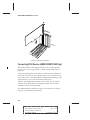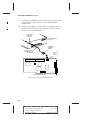
1
User’s Guide
AMM-1525M/1510M/525M
SCSI Audio Host Adapters and Sound Cards
A
AAAAAAAAAAAAAAAAAAAAAAAAAAAAAAAAAAAAAAAAAAAAAAAAAAAAAAAAAAAAA
AA
A
AMM-1525M/1510M/525M User’s Guide
A
AA
A
A
Stock Number: 510660-00, Rev. A
Page: Front Cover AA
A
A
AA
A
Print Spec Number: 492932-00
A
AA
A
A
Current Date: 9/20/94
ECN Date: 9/27/94 AA
A
AAAA
A
AAAAAAAA
AAAAAAAA
AAAAAAAA
AAAAAAAA
AAAAAAAA
AAAAAAAA
AAAAAAAA
AAAAAAAA
AAAAAAAA
AAAAAAAA
AAAAAAAA
AAAAAAAA
AAAAAAAA
AAAAAAAA
AAAAAA
Adaptec, Inc.
691 South Milpitas Boulevard
Milpitas, CA 95035
Copyright © 1994, Adaptec, Inc.
All rights reserved. Adaptec and the
Adaptec logo are registered trademarks
of Adaptec, Inc.
Printed in Singapore
STOCK NO.: 510660-00, Rev. A RQ 9/94
A
AAAAAAAAAAAAAAAAAAAAAAAAAAAAAAAAAAAAAAAAAAAAAAAAAAAAAAAAAAAAA
AA
A
AMM-1525M/1510M/525M User’s Guide
A
AA
A
A
Stock Number: 510660-00, Rev. A
Page: Back Cover AA
A
A
AA
A
Print Spec Number: 492932-00
A
AA
A
A
Current Date: 9/20/94
ECN Date: 9/27/94 AA
A
AAAA
A
AAAAAAAA
AAAAAAAA
AAAAAAAA
AAAAAAAA
AAAAAAAA
AAAAAAAA
AAAAAAAA
AAAAAAAA
AAAAAAAA
AAAAAAAA
AAAAAAAA
AAAAAAAA
AAAAAAAA
AAAAAAAA
AAAAAA
▼ ▼ ▼ ▼
AMM-1525M/1510M/525M
SCSI Audio Host Adapters and Sound Cards
User’s Guide
R
A
AAAAAAAAAAAAAAAAAAAAAAAAAAAAAAAAAAAAAAAAAAAAAAAAAAAAAAAAAAAAA
AA
A
AMM-1525M/1510M/525M User’s Guide
A
AA
A
A
Stock Number: 510660-00, Rev. A
Page: i AA
A
A
AA
A
Print Spec Number: 492932-00
A
AA
A
A
Current Date: 9/20/94
ECN Date: 9/27/94 AA
A
AAAA
A
AAAAAAAA
AAAAAAAA
AAAAAAAA
AAAAAAAA
AAAAAAAA
AAAAAAAA
AAAAAAAA
AAAAAAAA
AAAAAAAA
AAAAAAAA
AAAAAAAA
AAAAAAAA
AAAAAAAA
AAAAAAAA
AAAAAA
Copyright
Copyright © 1994 Adaptec, Inc. All rights reserved. No part of this publication may
be reproduced, stored in a retrieval system, or transmitted in any form or by any
means, electronic, mechanical, photocopying, recording or otherwise, without the
prior written consent of Adaptec, Inc., 691 South Milpitas Blvd., Milpitas, CA 95035.
Trademarks
Adaptec, the Adaptec logo, AMM, DeMucker, EZ-Audio, and EZ-SCSI are trademarks of Adaptec, Inc. which may be registered in some jurisdictions.
Sound Blaster is a trademark of Creative Technology Ltd.
MS-DOS is a registered trademark of Microsoft Corporation.
OS/2, Micro Channel, IBM, and PC-AT are registered trademarks of International
Business Machines Corporation.
VL-Bus is a trademark of Video Electronics Standards Association.
All other trademarks are owned by their respective owners.
Changes
The material in this document is for information only and is subject to change without notice. While reasonable efforts have been made in the preparation of this document to assure its accuracy, Adaptec, Inc. assumes no liability resulting from errors or
omissions in this document, or from the use of the information contained herein.
Adaptec reserves the right to make changes in the product design without reservation
and without notification to its users.
Adaptec Technical Support
Adaptec products have been specifically developed for easy installation and use. We
believe that our documents and the onscreen instructions and help are complete and
clear enough to meet your needs. If you need more assistance, please contact us.
●
The Adaptec Electronic Bulletin Board Service (BBS) provides information on software upgrades, new releases, technical advice, and other topics. The BBS is available 23 hours a day at 408-945-7727; 1200/2400/9600/14400 baud, 8 data bits,
1stop bit, no parity. The BBS is out of service 1 hour each day. If you cannot reach
the BBS, wait an hour and try again.
●
To contact the Adaptec Technical Support Hot Line, call 800-959-SCSI (7274) or
408-945-2550; M–F: 6:00 a.m. to 5:00 p.m., Pacific Time.
Interactive Fax Service
The Adaptec Interactive Fax Service provides the latest online information about
Adaptec products and services. The Adaptec Interactive Fax Service is available
23 hours a day, 7 days a week, at 408-957-7150. The Fax is out of service 1 hour each
day.
Ordering Software and Cables
To order Adaptec software and SCSI cables, call 800-442-SCSI (7274), M–F: 6:00 a.m. to
5:00 p.m., Pacific Time. If you are calling from outside the U.S. and Canada, the number is 408-957-SCSI (7274).
ii
A
AAAAAAAAAAAAAAAAAAAAAAAAAAAAAAAAAAAAAAAAAAAAAAAAAAAAAAAAAAAAA
AA
A
AMM-1525M/1510M/525M User’s Guide
A
AA
A
A
Stock Number: 510660-00, Rev. A
Page: ii AA
A
A
AA
A
Print Spec Number: 492932-00
A
AA
A
A
Current Date: 9/20/94
ECN Date: 9/27/94 AA
A
AAAA
A
AAAAAAAA
AAAAAAAA
AAAAAAAA
AAAAAAAA
AAAAAAAA
AAAAAAAA
AAAAAAAA
AAAAAAAA
AAAAAAAA
AAAAAAAA
AAAAAAAA
AAAAAAAA
AAAAAAAA
AAAAAAAA
AAAAAA
Literature Hotline
To request additional documentation for Adaptec products, call 800-934-2766,
M–F: 5:00 a.m. to 6:00 p.m., Pacific Time.
FCC Compliance Statement
This equipment has been tested and found to comply with the limits for a Class B digital device,
pursuant to Part 15 of the FCC rules. These limits are designed to provide reasonable protection
against harmful interference in residential installations. This equipment generates, uses, and can
radiate radio frequency energy, and if not installed and used in accordance with the instructions,
may cause harmful interference to radio communications. However, there is no guarantee that
interference will not occur in a particular installation.
If this equipment does cause interference to radio or television equipment reception, which can be
determined by turning the equipment off and on, the user is encouraged to try to correct the interference by one or more of the following measures:
• Reorient or relocate the receiving antenna
• Move the equipment away from the receiver
• Plug the equipment into an outlet on a circuit different from that to which the receiver is
powered
• If necessary, the user should consult the dealer or an experienced radio/television technician
for additional suggestions
CAUTION: Only equipment certified to comply with Class B (computer input/output devices,
terminals, printers, etc.) should be attached to this equipment, and must have shielded interface
cables.
Finally, any changes or modifications to the equipment by the user not expressly approved by the
grantee or manufacturer could void the user ’s authority to operate such equipment.
Each host adapter is equipped with an FCC compliance label which shows only the FCC identification number. The full text of the associated label follows:
This device complies with part 15 of the FCC rules. Operation is subject to the following
two conditions: (1) this device may not cause harmful interference and (2) this device
must accept any interference received, including interference that may cause undesired
operation.
iii
A
AAAAAAAAAAAAAAAAAAAAAAAAAAAAAAAAAAAAAAAAAAAAAAAAAAAAAAAAAAAAA
AA
A
AMM-1525M/1510M/525M User’s Guide
A
AA
A
A
Stock Number: 510660-00, Rev. A
Page: iii AA
A
A
AA
A
Print Spec Number: 492932-00
A
AA
A
A
Current Date: 9/20/94
ECN Date: 9/27/94 AA
A
AAAA
A
AAAAAAAA
AAAAAAAA
AAAAAAAA
AAAAAAAA
AAAAAAAA
AAAAAAAA
AAAAAAAA
AAAAAAAA
AAAAAAAA
AAAAAAAA
AAAAAAAA
AAAAAAAA
AAAAAAAA
AAAAAAAA
AAAAAA
A
AAAAAAAAAAAAAAAAAAAAAAAAAAAAAAAAAAAAAAAAAAAAAAAAAAAAAAAAAAAAA
AA
A
AMM-1525M/1510M/525M User’s Guide
A
AA
A
A
Stock Number: 510660-00, Rev. A
Page: iv AA
A
A
AA
A
Print Spec Number: 492932-00
A
AA
A
A
Current Date: 9/20/94
ECN Date: 9/27/94 AA
A
AAAA
A
AAAAAAAA
AAAAAAAA
AAAAAAAA
AAAAAAAA
AAAAAAAA
AAAAAAAA
AAAAAAAA
AAAAAAAA
AAAAAAAA
AAAAAAAA
AAAAAAAA
AAAAAAAA
AAAAAAAA
AAAAAAAA
AAAAAA
▼ ▼ ▼ ▼
Table of Contents
Preface
Inside This Document ix
Conventions x
Advisories xi
1 Introduction
About This Chapter 1-1
Overview 1-3
System Requirements 1-3
Features 1-4
SCSI Features 1-4
IDE Features 1-5
Audio Features 1-5
Adaptec Software 1-6
Types of Cables Required 1-6
Product Specifications 1-7
Physical Dimensions 1-7
Power Requirements 1-7
Temperature Requirements 1-7
2 Installation
About This Chapter 2-1
Installation Overview 2-3
Host Adapter Layout 2-4
Default Settings 2-5
Setting Jumpers 2-6
Installing and Removing Jumper Connectors 2-6
Interrupt Channel (IRQ) (AMM-1525M/1510M
Only) 2-6
I/O Port Address (AMM-1525M/1510M Only) 2-7
Sound Chip Base Address 2-7
IDE Port Address (AMM-1525M/525M Only) 2-7
IDE Port Enable (AMM-1525M/525M Only) 2-8
v
A
AAAAAAAAAAAAAAAAAAAAAAAAAAAAAAAAAAAAAAAAAAAAAAAAAAAAAAAAAAAAA
AA
A
AMM-1525M/1510M/525M User’s Guide
A
AA
A
A
Stock Number: 510660-00, Rev. A
Page: v AA
A
A
AA
A
Print Spec Number: 492932-00
A
AA
A
A
Current Date: 9/20/94
ECN Date: 9/27/94 AA
A
AAAA
A
AAAAAAAA
AAAAAAAA
AAAAAAAA
AAAAAAAA
AAAAAAAA
AAAAAAAA
AAAAAAAA
AAAAAAAA
AAAAAAAA
AAAAAAAA
AAAAAAAA
AAAAAAAA
AAAAAAAA
AAAAAAAA
AAAAAA
AMM-1525M/1510M/525M User’s Guide
Installing the Host Adapter 2-8
Connecting SCSI Devices (AMM-1525M/1510M
Only) 2-10
Connecting Internal SCSI Devices 2-11
Terminating the SCSI Bus 2-14
Setting SCSI IDs 2-15
Connecting IDE Devices (AMM-1525M/525M
Only) 2-16
Connecting Audio Equipment 2-20
Audio Input/Output Jacks 2-20
Using Audio with Internal CD-ROM Drives 2-21
Using Audio with External CD-ROM Drives 2-23
Running the Adaptec Installation Manager 2-24
Adaptec DeMucker 2-25
Adaptec EZ-SCSI 2-25
Install ATAPI CD-ROM Driver 2-25
Adaptec EZ-Audio 2-25
Microsoft Windows Sound System 2-25
3 IDE Configuration
About This Chapter 3-1
IDE Overview 3-3
Multiple IDE Controllers 3-3
Configuring the Computer’s CMOS Setup 3-4
A Troubleshooting
About This Appendix A-1
SCSI Problems and Solutions A-3
Troubleshooting Checklist A-3
Operating Problems A-4
aspi2dos.sys Error Messages A-5
aspidisk.sys Error Messages A-5
Other Error Messages A-6
IDE Problems and Solutions A-7
Audio Problems and Solutions A-7
vi
A
AAAAAAAAAAAAAAAAAAAAAAAAAAAAAAAAAAAAAAAAAAAAAAAAAAAAAAAAAAAAA
AA
A
AMM-1525M/1510M/525M User’s Guide
A
AA
A
A
Stock Number: 510660-00, Rev. A
Page: vi AA
A
A
AA
A
Print Spec Number: 492932-00
A
AA
A
A
Current Date: 9/20/94
ECN Date: 9/27/94 AA
A
AAAA
A
AAAAAAAA
AAAAAAAA
AAAAAAAA
AAAAAAAA
AAAAAAAA
AAAAAAAA
AAAAAAAA
AAAAAAAA
AAAAAAAA
AAAAAAAA
AAAAAAAA
AAAAAAAA
AAAAAAAA
AAAAAAAA
AAAAAA
▼ ▼ ▼ ▼
List of Figures
Figure
2-1
2-2
2-3
2-4
2-5
AMM-1525M/1510M/525M Layout 2-4
2-6
2-7
2-8
Connecting a Second Internal SCSI Device 2-13
2-9
Connecting the IDE Ribbon Cable to the First IDE
Drive 2-18
2-10
2-11
Connecting a Second IDE Drive 2-19
2-12
Connecting the CD-ROM Audio Cable 2-22
Unused Expansion Bus Slot 2-9
Installing the Host Adapter 2-10
50-pin SCSI Ribbon Cable to Host Adapter 2-12
50-pin SCSI Ribbon Cable to Internal SCSI
Device 2-13
Termination With Internal Devices Only 2-14
Connecting the IDE Ribbon Cable to the Host
Adapter 2-17
Connecting Audio Equipment to the Host
Adapter 2-20
vii
A
AAAAAAAAAAAAAAAAAAAAAAAAAAAAAAAAAAAAAAAAAAAAAAAAAAAAAAAAAAAAA
AA
A
AMM-1525M/1510M/525M User’s Guide
A
AA
A
A
Stock Number: 510660-00, Rev. A
Page: vii AA
A
A
AA
A
Print Spec Number: 492932-00
A
AA
A
A
Current Date: 9/20/94
ECN Date: 9/27/94 AA
A
AAAA
A
AAAAAAAA
AAAAAAAA
AAAAAAAA
AAAAAAAA
AAAAAAAA
AAAAAAAA
AAAAAAAA
AAAAAAAA
AAAAAAAA
AAAAAAAA
AAAAAAAA
AAAAAAAA
AAAAAAAA
AAAAAAAA
AAAAAA
A
AAAAAAAAAAAAAAAAAAAAAAAAAAAAAAAAAAAAAAAAAAAAAAAAAAAAAAAAAAAAA
AA
A
AMM-1525M/1510M/525M User’s Guide
A
AA
A
A
Stock Number: 510660-00, Rev. A
Page: viii AA
A
A
AA
A
Print Spec Number: 492932-00
A
AA
A
A
Current Date: 9/20/94
ECN Date: 9/27/94 AA
A
AAAA
A
AAAAAAAA
AAAAAAAA
AAAAAAAA
AAAAAAAA
AAAAAAAA
AAAAAAAA
AAAAAAAA
AAAAAAAA
AAAAAAAA
AAAAAAAA
AAAAAAAA
AAAAAAAA
AAAAAAAA
AAAAAAAA
AAAAAA
▼ ▼ ▼ ▼
Preface
Inside This Document
This document provides complete instructions on
how to install and use the Adaptec AMM™-1525M,
AMM-1510M, and AMM-525M SCSI Audio Host
Adapters and Sound Cards in your computer.
Chapter 1
Introduction
provides general information about and lists the features of the AMM-1525M/1510M/525M.
Chapter 2
Installation
has the information needed to install the host adapter,
SCSI devices, IDE devices, Audio devices, and
Adaptec software.
Chapter 3
IDE Configuration
describes how to configure your IDE devices for use
with your AMM-1525M/525M host adapter and
computer.
Appendix A
Troubleshooting
has information to assist you in troubleshooting
problems that may occur during installation and
operation.
ix
A
AAAAAAAAAAAAAAAAAAAAAAAAAAAAAAAAAAAAAAAAAAAAAAAAAAAAAAAAAAAAA
AA
A
AMM-1525M/1510M/525M User’s Guide
A
AA
A
A
Stock Number: 510660-00, Rev. A
Page: ix AA
A
A
AA
A
Print Spec Number: 492932-00
A
AA
A
A
Current Date: 9/20/94
ECN Date: 9/27/94 AA
A
AAAA
A
AAAAAAAA
AAAAAAAA
AAAAAAAA
AAAAAAAA
AAAAAAAA
AAAAAAAA
AAAAAAAA
AAAAAAAA
AAAAAAAA
AAAAAAAA
AAAAAAAA
AAAAAAAA
AAAAAAAA
AAAAAAAA
AAAAAA
AMM-1525M/1510M/525M User’s Guide
Conventions
The following typographic conventions are used in
this document.
bold
Used for keystrokes (… press the Enter key …), and
screen selection fields (… select Advanced Configuration Options …)
Helvetica
Used for operator entry that must be typed exactly as
shown (… device=c:\scsi\aspi2dos.sys …) and for
messages on the screen (… Enter Password …).
Helvetica Italics
Used as a place holder for text you must determine
and type in (… enter nn for number …). Also used for
program and file names that appear in body text
(… the autoexec.bat file …).
Italics
Used for emphasis (… is only supported …) and for
document references (… refer to Chapter 1,
Introduction…).
Hexadecimal Numbers
Are followed by an ‘h’, e.g., 330h.
End Mark
The ❐ symbol marks the end of a chapter or other
section.
x
A
AAAAAAAAAAAAAAAAAAAAAAAAAAAAAAAAAAAAAAAAAAAAAAAAAAAAAAAAAAAAA
AA
A
AMM-1525M/1510M/525M User’s Guide
A
AA
A
A
Stock Number: 510660-00, Rev. A
Page: x AA
A
A
AA
A
Print Spec Number: 492932-00
A
AA
A
A
Current Date: 9/20/94
ECN Date: 9/27/94 AA
A
AAAA
A
AAAAAAAA
AAAAAAAA
AAAAAAAA
AAAAAAAA
AAAAAAAA
AAAAAAAA
AAAAAAAA
AAAAAAAA
AAAAAAAA
AAAAAAAA
AAAAAAAA
AAAAAAAA
AAAAAAAA
AAAAAAAA
AAAAAA
Preface
Advisories
Advisories are quick notes that stress an important
point or warn of a potential hazard to you or your
system. This document uses three kinds of advisories:
Note: Text set off in this way presents reminders, tips, or suggestions that may make it easier for you to install, configure, and use your
host adapter.
Caution: Failure to observe this kind of advisory could result in loss of data or damage to
your system and installed devices.
WARNING: Failure to observe this kind of
advisory could result in personal injury.
Use caution when handling any electrical equipment.
Advisories in this document can only cover the procedures contained here, and not all situations may have
been addressed. Adaptec does not claim to have
included every condition or situation that might
require a Caution or Warning. You must refer to the
documentation for your computer peripheral equipment when you are installing equipment or changing
its configuration.
❒
xi
A
AAAAAAAAAAAAAAAAAAAAAAAAAAAAAAAAAAAAAAAAAAAAAAAAAAAAAAAAAAAAA
AA
A
AMM-1525M/1510M/525M User’s Guide
A
AA
A
A
Stock Number: 510660-00, Rev. A
Page: xi AA
A
A
AA
A
Print Spec Number: 492932-00
A
AA
A
A
Current Date: 9/20/94
ECN Date: 9/27/94 AA
A
AAAA
A
AAAAAAAA
AAAAAAAA
AAAAAAAA
AAAAAAAA
AAAAAAAA
AAAAAAAA
AAAAAAAA
AAAAAAAA
AAAAAAAA
AAAAAAAA
AAAAAAAA
AAAAAAAA
AAAAAAAA
AAAAAAAA
AAAAAA
A
AAAAAAAAAAAAAAAAAAAAAAAAAAAAAAAAAAAAAAAAAAAAAAAAAAAAAAAAAAAAA
AA
A
AMM-1525M/1510M/525M User’s Guide
A
AA
A
A
Stock Number: 510660-00, Rev. A
Page: xii AA
A
A
AA
A
Print Spec Number: 492932-00
A
AA
A
A
Current Date: 9/20/94
ECN Date: 9/27/94 AA
A
AAAA
A
AAAAAAAA
AAAAAAAA
AAAAAAAA
AAAAAAAA
AAAAAAAA
AAAAAAAA
AAAAAAAA
AAAAAAAA
AAAAAAAA
AAAAAAAA
AAAAAAAA
AAAAAAAA
AAAAAAAA
AAAAAAAA
AAAAAA
▼ ▼ ▼ ▼
1
Introduction
About This Chapter
Read this chapter to find out
■
An overview of the AMM-1525M/1510M/
525M
■
The minimum system requirements needed
to install the AMM-1525M/1510M/525M
■
The features of the AMM-1525M/1510M/
525M
■
General information on using the
AMM-1525M/1510M/525M
1-1
A
AAAAAAAAAAAAAAAAAAAAAAAAAAAAAAAAAAAAAAAAAAAAAAAAAAAAAAAAAAAAA
AA
A
AMM-1525M/1510M/525M User’s Guide
A
AA
A
A
Stock Number: 510660-00, Rev. A
Page: 1-1 AA
A
A
AA
A
Print Spec Number: 492932-00
A
AA
A
A
Current Date: 9/20/94
ECN Date: 9/27/94 AA
A
AAAA
A
AAAAAAAA
AAAAAAAA
AAAAAAAA
AAAAAAAA
AAAAAAAA
AAAAAAAA
AAAAAAAA
AAAAAAAA
AAAAAAAA
AAAAAAAA
AAAAAAAA
AAAAAAAA
AAAAAAAA
AAAAAAAA
AAAAAA
A
AAAAAAAAAAAAAAAAAAAAAAAAAAAAAAAAAAAAAAAAAAAAAAAAAAAAAAAAAAAAA
AA
A
AMM-1525M/1510M/525M User’s Guide
A
AA
A
A
Stock Number: 510660-00, Rev. A
Page: 1-2 AA
A
A
AA
A
Print Spec Number: 492932-00
A
AA
A
A
Current Date: 9/20/94
ECN Date: 9/27/94 AA
A
AAAA
A
AAAAAAAA
AAAAAAAA
AAAAAAAA
AAAAAAAA
AAAAAAAA
AAAAAAAA
AAAAAAAA
AAAAAAAA
AAAAAAAA
AAAAAAAA
AAAAAAAA
AAAAAAAA
AAAAAAAA
AAAAAAAA
AAAAAA
Introduction
▼ ▼ ▼ ▼
1
Overview
This document provides information on how to install and configure the Adaptec AMM-1525M, AMM-1510M, and AMM-525M SCSI
Audio Host Adapters and Sound Cards.
Each adapter provides superior audio performance for your multimedia devices. Through the input and output jacks, a variety of
audio equipment can be connected.
In addition, the AMM-1525M allows you to connect up to seven
internal SCSI devices, and up to two IDE devices (IDE hard disk
and/or ATAPI CD-ROM drive); the AMM-1510M allows you to connect up to seven internal SCSI devices; and the AMM-525M allows
you to connect up to two IDE devices.
Collectively, all three boards are referred to in this document as the
AMM-1525M/1510M/525M; the two adapters that provide full SCSI
host adapter functionality are referred to as the AMM-1525M/
1510M; and the two adapters that provide IDE support are referred
to as the AMM-1525M/525M.
System Requirements
The following minimum requirements are needed to install the
AMM-1525M/1510M/525M:
■
An 80386SX 25 megahertz (MHz) computer or higher
■
An available 16-bit expansion bus slot
The following are additional requirements needed to run the
Windows version of the Adaptec Installation Manager:
■
Microsoft Windows 3.1x
■
Four megabytes (MByte) or more of RAM
■
A Video Graphics Array (VGA) monitor and VGA display card
■
A hard disk with 10 MBytes or more of free space
■
A 3.5-inch, high-density (1.44-MByte) floppy disk drive
1-3
A
AAAAAAAAAAAAAAAAAAAAAAAAAAAAAAAAAAAAAAAAAAAAAAAAAAAAAAAAAAAAA
AA
A
AMM-1525M/1510M/525M User’s Guide
A
AA
A
A
Stock Number: 510660-00, Rev. A
Page: 1-3 AA
A
A
AA
A
Print Spec Number: 492932-00
A
AA
A
A
Current Date: 9/20/94
ECN Date: 9/27/94 AA
A
AAAA
A
AAAAAAAA
AAAAAAAA
AAAAAAAA
AAAAAAAA
AAAAAAAA
AAAAAAAA
AAAAAAAA
AAAAAAAA
AAAAAAAA
AAAAAAAA
AAAAAAAA
AAAAAAAA
AAAAAAAA
AAAAAAAA
AAAAAA
AMM-1525M/1510M/525M User’s Guide
Features
SCSI Features
Configuration Flexibility
■
One internal 50-pin SCSI connector for connecting standard
8-bit internal SCSI devices
■
Provides easy installation and use with Adaptec Installation
Manager software
Multiple Device and Applications Support
■
Supports up to seven individually configured SCSI devices,
simultaneously
■
Supports hard disk drives, removable magneto-optical drives,
CD-ROM drives, and Photo CD
■
Compatible with DOS, Windows, third-party software, and
SCSI-1 and SCSI-2 peripherals
■
Operating system support available for DOS and Windows
Data Transfer Rates
■
Up to 10 MBytes/sec maximum SCSI transfer rate (Fast SCSI)
■
Up to 5.0 MBytes/sec synchronous burst rate on the SCSI bus
■
Up to 3.0 MBytes/sec data rate on the ISA bus
■
Up to 2.0 MBytes/sec asynchronous SCSI data rate
Maximum Off-loading the Host CPU
■
Low SCSI processing overhead
■
Task scheduling and message-based communication
■
16-bit host ISA bus data transfer
■
32-bit PIO transfers with 80386 processors and above
Advanced Fast SCSI-2 Implementation
■
Concurrent support of Fast SCSI, synchronous, and
asynchronous devices
■
Single-ended output
1-4
A
AAAAAAAAAAAAAAAAAAAAAAAAAAAAAAAAAAAAAAAAAAAAAAAAAAAAAAAAAAAAA
AA
A
AMM-1525M/1510M/525M User’s Guide
A
AA
A
A
Stock Number: 510660-00, Rev. A
Page: 1-4 AA
A
A
AA
A
Print Spec Number: 492932-00
A
AA
A
A
Current Date: 9/20/94
ECN Date: 9/27/94 AA
A
AAAA
A
AAAAAAAA
AAAAAAAA
AAAAAAAA
AAAAAAAA
AAAAAAAA
AAAAAAAA
AAAAAAAA
AAAAAAAA
AAAAAAAA
AAAAAAAA
AAAAAAAA
AAAAAAAA
AAAAAAAA
AAAAAAAA
AAAAAA
Introduction
■
Disconnect/Reconnect
■
Fully multitasking/multithreading
■
Parity checking
IDE Features
■
Provides one internal 40-pin IDE connector for IDE devices
such as standard IDE hard disk and ATAPI CD-ROM drives
■
Supports up to two IDE devices
■
Supports primary or secondary IDE port address
■
Provides ATAPI CD-ROM device driver through Adaptec
Installation Manager
Audio Features
■
Digital audio recording and playback with compression
■
Audio FM and wavetable synthesis
■
Musical Instrument Digital Interface (MIDI) recording and
playback
■
Roland MPU-401 compatible MIDI port
■
Joystick game port interface
■
CD, Line, and Microphone inputs
■
Line outputs
■
Speaker outputs
■
16-bit quality sound/stereo
■
Windows Sound System compatibility
■
Sound Blaster compatibility
■
16-bit, 8-bit or compressed 4-bits per sample, IMA Adpcm,
TrueSpeech Adpcm
■
Sampling rates: 8, 11, 22, and 44.1 KHz (selectable)
■
Stereo or mono modes (including pseudo-stereo and special
effects)
■
Onboard tone control
■
Onboard stereo speaker amplifier
1-5
A
AAAAAAAAAAAAAAAAAAAAAAAAAAAAAAAAAAAAAAAAAAAAAAAAAAAAAAAAAAAAA
AA
A
AMM-1525M/1510M/525M User’s Guide
A
AA
A
A
Stock Number: 510660-00, Rev. A
Page: 1-5 AA
A
A
AA
A
Print Spec Number: 492932-00
A
AA
A
A
Current Date: 9/20/94
ECN Date: 9/27/94 AA
A
AAAA
A
AAAAAAAA
AAAAAAAA
AAAAAAAA
AAAAAAAA
AAAAAAAA
AAAAAAAA
AAAAAAAA
AAAAAAAA
AAAAAAAA
AAAAAAAA
AAAAAAAA
AAAAAAAA
AAAAAAAA
AAAAAAAA
AAAAAA
AMM-1525M/1510M/525M User’s Guide
Adaptec Software
The AMM-1525M/1510M/525M kit is shipped with the Adaptec
Installation Manager software utility. The Installation Manager
allows you to easily run and install all of the Adaptec Software
needed to provide your host adapter with audio and SCSI capabilities. Refer to Running the Adaptec Installation Manager on page 2-24
and the Installation Manager User’s Guide for more information.
Types of Cables Required
Before you actually install the host adapter, be sure you have the correct cables for your particular installation. The type of cables
required depends on the type of devices you plan to connect to the
host adapter: either internal SCSI or IDE devices.
Type of Connector
on Host Adapter
Type of Cable
Type of Connector on Cable
Internal SCSI
50-pin SCSI ribbon cable
Unshrouded 50-pin header, compatible with unshielded Alternative
2 connector.
IDE
40-pin IDE ribbon cable
Unshrouded 40-pin header
connector
1-6
A
AAAAAAAAAAAAAAAAAAAAAAAAAAAAAAAAAAAAAAAAAAAAAAAAAAAAAAAAAAAAA
AA
A
AMM-1525M/1510M/525M User’s Guide
A
AA
A
A
Stock Number: 510660-00, Rev. A
Page: 1-6 AA
A
A
AA
A
Print Spec Number: 492932-00
A
AA
A
A
Current Date: 9/20/94
ECN Date: 9/27/94 AA
A
AAAA
A
AAAAAAAA
AAAAAAAA
AAAAAAAA
AAAAAAAA
AAAAAAAA
AAAAAAAA
AAAAAAAA
AAAAAAAA
AAAAAAAA
AAAAAAAA
AAAAAAAA
AAAAAAAA
AAAAAAAA
AAAAAAAA
AAAAAA
Introduction
Product Specifications
The basic technical specifications of the host adapter are described
below. If you need more detailed information, contact Adaptec’s
Literature Department at the phone number listed on page ii.
Physical Dimensions
Length:
Width:
Height:
9.85-inches
0.44-inches
4.50-inches
Power Requirements
+5.0 +/- 0.25 Volts at 2.0 Amps maximum
Temperature Requirements
Operating:
Storage:
0°C (32°F) to 55°C (131°F)
-40°C (-40°F) to 75°C (167°F)
❒
1-7
A
AAAAAAAAAAAAAAAAAAAAAAAAAAAAAAAAAAAAAAAAAAAAAAAAAAAAAAAAAAAAA
AA
A
AMM-1525M/1510M/525M User’s Guide
A
AA
A
A
Stock Number: 510660-00, Rev. A
Page: 1-7 AA
A
A
AA
A
Print Spec Number: 492932-00
A
AA
A
A
Current Date: 9/20/94
ECN Date: 9/27/94 AA
A
AAAA
A
AAAAAAAA
AAAAAAAA
AAAAAAAA
AAAAAAAA
AAAAAAAA
AAAAAAAA
AAAAAAAA
AAAAAAAA
AAAAAAAA
AAAAAAAA
AAAAAAAA
AAAAAAAA
AAAAAAAA
AAAAAAAA
AAAAAA
A
AAAAAAAAAAAAAAAAAAAAAAAAAAAAAAAAAAAAAAAAAAAAAAAAAAAAAAAAAAAAA
AA
A
AMM-1525M/1510M/525M User’s Guide
A
AA
A
A
Stock Number: 510660-00, Rev. A
Page: 1-8 AA
A
A
AA
A
Print Spec Number: 492932-00
A
AA
A
A
Current Date: 9/20/94
ECN Date: 9/27/94 AA
A
AAAA
A
AAAAAAAA
AAAAAAAA
AAAAAAAA
AAAAAAAA
AAAAAAAA
AAAAAAAA
AAAAAAAA
AAAAAAAA
AAAAAAAA
AAAAAAAA
AAAAAAAA
AAAAAAAA
AAAAAAAA
AAAAAAAA
AAAAAA
▼ ▼ ▼ ▼
2
Installation
About This Chapter
Read this chapter to find out
■
An overview of installing your host adapter
and peripheral devices
■
The layout of the host adapter
■
The default settings of the host adapter
■
Jumper settings and how to change them
■
Instructions for installing the host adapter,
SCSI devices, IDE devices, and audio
equipment
■
Instructions for installing the Adaptec
software necessary for SCSI and audio
operation
2-1
A
AAAAAAAAAAAAAAAAAAAAAAAAAAAAAAAAAAAAAAAAAAAAAAAAAAAAAAAAAAAAA
AA
A
AMM-1525M/1510M/525M User’s Guide
A
AA
A
A
Stock Number: 510660-00, Rev. A
Page: 2-1 AA
A
A
AA
A
Print Spec Number: 492932-00
A
AA
A
A
Current Date: 9/20/94
ECN Date: 9/27/94 AA
A
AAAA
A
AAAAAAAA
AAAAAAAA
AAAAAAAA
AAAAAAAA
AAAAAAAA
AAAAAAAA
AAAAAAAA
AAAAAAAA
AAAAAAAA
AAAAAAAA
AAAAAAAA
AAAAAAAA
AAAAAAAA
AAAAAAAA
AAAAAA
A
AAAAAAAAAAAAAAAAAAAAAAAAAAAAAAAAAAAAAAAAAAAAAAAAAAAAAAAAAAAAA
AA
A
AMM-1525M/1510M/525M User’s Guide
A
AA
A
A
Stock Number: 510660-00, Rev. A
Page: 2-2 AA
A
A
AA
A
Print Spec Number: 492932-00
A
AA
A
A
Current Date: 9/20/94
ECN Date: 9/27/94 AA
A
AAAA
A
AAAAAAAA
AAAAAAAA
AAAAAAAA
AAAAAAAA
AAAAAAAA
AAAAAAAA
AAAAAAAA
AAAAAAAA
AAAAAAAA
AAAAAAAA
AAAAAAAA
AAAAAAAA
AAAAAAAA
AAAAAAAA
AAAAAA
Installation
▼ ▼ ▼ ▼
2
Installation Overview
This chapter guides you through installing your host adapter and
peripheral devices. An overview of the installation steps is listed
below. The steps should be performed in the order they appear. See
the referenced section for installation details:
1
Setting switches and jumpers on the host adapter—see Setting
Jumpers on page 2-6.
2
Installing the host adapter in the computer—see Installing the
Host Adapter on page 2-8.
3
Connecting SCSI cables and SCSI peripheral devices—see
Connecting SCSI Devices (AMM-1525M/1510M Only) on page
2-10.
4
Terminating the SCSI bus—see Terminating the SCSI Bus on
page 2-14.
5
6
Setting SCSI IDs—see Setting SCSI IDs on page 2-15.
7
Installing Adaptec software—see Running the Adaptec Installation Manager on page 2-24.
8
Configuring the computer to use IDE devices—see Chapter 3,
IDE Configuration.
Connecting IDE devices—see Connecting IDE Devices
(AMM-1525M/525M Only) on page 2-16.
2-3
A
AAAAAAAAAAAAAAAAAAAAAAAAAAAAAAAAAAAAAAAAAAAAAAAAAAAAAAAAAAAAA
AA
A
AMM-1525M/1510M/525M User’s Guide
A
AA
A
A
Stock Number: 510660-00, Rev. A
Page: 2-3 AA
A
A
AA
A
Print Spec Number: 492932-00
A
AA
A
A
Current Date: 9/20/94
ECN Date: 9/27/94 AA
A
AAAA
A
AAAAAAAA
AAAAAAAA
AAAAAAAA
AAAAAAAA
AAAAAAAA
AAAAAAAA
AAAAAAAA
AAAAAAAA
AAAAAAAA
AAAAAAAA
AAAAAAAA
AAAAAAAA
AAAAAAAA
AAAAAAAA
AAAAAA
AMM-1525M/1510M/525M User’s Guide
Host Adapter Layout
Figure 2-1 shows the major components on the AMM-1525M/
1510M/525M.
IDE/ATAPI
Connector
(AMM-1525M/525M)
Internal
SCSI Connector
(AMM-1525M/1510M)
CD Audio
Input Connector
Headphones/
Speakers
J3
J4
Line Out
Line In
J10
J9
Wavetable ROM
AIC-6360 SCSI
Protocol Chip
(AMM-1525M/1510M)
Bus Interface
Chip
Sound Chip
Game/MIDI Port
J10 (AMM1525M/1510M)
Microphone
Figure 2-1. AMM-1525M/1510M/525M Layout
2-4
A
AAAAAAAAAAAAAAAAAAAAAAAAAAAAAAAAAAAAAAAAAAAAAAAAAAAAAAAAAAAAA
AA
A
AMM-1525M/1510M/525M User’s Guide
A
AA
A
A
Stock Number: 510660-00, Rev. A
Page: 2-4 AA
A
A
AA
A
Print Spec Number: 492932-00
A
AA
A
A
Current Date: 9/20/94
ECN Date: 9/27/94 AA
A
AAAA
A
AAAAAAAA
AAAAAAAA
AAAAAAAA
AAAAAAAA
AAAAAAAA
AAAAAAAA
AAAAAAAA
AAAAAAAA
AAAAAAAA
AAAAAAAA
AAAAAAAA
AAAAAAAA
AAAAAAAA
AAAAAAAA
AAAAAA
Installation
Default Settings
Your host adapter is already configured for the majority of computers. The table below lists the default settings.
Description
Default Setting
Configured By
AMM-1525M/1510M/525M:
Sound Chip Base Address
220h
J9
IDE Port Address
Secondary (170h - 177h)
J4
IDE Port Enable
Enabled
J4
AMM-1525M/525M:
AMM-1525M/1510M:
1
Interrupt Channel (IRQ)
11
J10
I/O Port Address
340h - 35Eh
J10
Host Adapter Termination
Enabled1
Host Adapter SCSI ID
7
–
aspi2dos.sys2
Host adapter termination is always enabled and cannot be changed.
the aspi2dos.sys command line; see The aspi2dos.sys ASPI Manager in
your Adaptec EZ-SCSI User’s Guide.
2 Setting configured through
Note: Always refer to the documentation provided with your
system for instructions on adding and configuring adapter
boards.
2-5
A
AAAAAAAAAAAAAAAAAAAAAAAAAAAAAAAAAAAAAAAAAAAAAAAAAAAAAAAAAAAAA
AA
A
AMM-1525M/1510M/525M User’s Guide
A
AA
A
A
Stock Number: 510660-00, Rev. A
Page: 2-5 AA
A
A
AA
A
Print Spec Number: 492932-00
A
AA
A
A
Current Date: 9/20/94
ECN Date: 9/27/94 AA
A
AAAA
A
AAAAAAAA
AAAAAAAA
AAAAAAAA
AAAAAAAA
AAAAAAAA
AAAAAAAA
AAAAAAAA
AAAAAAAA
AAAAAAAA
AAAAAAAA
AAAAAAAA
AAAAAAAA
AAAAAAAA
AAAAAAAA
AAAAAA
AMM-1525M/1510M/525M User’s Guide
Setting Jumpers
In most cases, you do not need to change any of the default jumper
settings; however, if you need to change any of them, do it before
installing your host adapter.
Installing and Removing Jumper Connectors
Configuring a jumper setting on the AMM-1525M/1510M/525M
involves installing or removing a small plastic jumper connector on
the pins of the jumper blocks. Installing a jumper (On) means to
install a small plastic jumper connector so that it covers both pins of
the jumper pin pair. Removing the jumper connector or having it
cover only one pin is the same as having no jumper installed (Off).
On
Off
Off
Interrupt Channel (IRQ) (AMM-1525M/1510M Only)
Pin pairs I2, I1, I0, and I9 on jumper block J10 allow you to configure
the IRQ for the host adapter.
Each AMM-1525M/1510M and expansion board installed in your
computer must be assigned a unique IRQ. The available settings are
= IRQ 12
I2 I1 I0 I9
= IRQ 11 *
I2 I1 I0 I9
= IRQ 10
I2 I1 I0 I9
= IRQ 9
I2 I1 I0 I9
* = Default
Note: IRQ 9 is not recommended with Windows 3.x.
2-6
A
AAAAAAAAAAAAAAAAAAAAAAAAAAAAAAAAAAAAAAAAAAAAAAAAAAAAAAAAAAAAA
AA
A
AMM-1525M/1510M/525M User’s Guide
A
AA
A
A
Stock Number: 510660-00, Rev. A
Page: 2-6 AA
A
A
AA
A
Print Spec Number: 492932-00
A
AA
A
A
Current Date: 9/20/94
ECN Date: 9/27/94 AA
A
AAAA
A
AAAAAAAA
AAAAAAAA
AAAAAAAA
AAAAAAAA
AAAAAAAA
AAAAAAAA
AAAAAAAA
AAAAAAAA
AAAAAAAA
AAAAAAAA
AAAAAAAA
AAAAAAAA
AAAAAAAA
AAAAAAAA
AAAAAA
Installation
I/O Port Address (AMM-1525M/1510M Only)
Pin pair PRI on jumper block J10 configures the I/O port address
range of the host adapter. Each AMM-1525M/1510M and expansion
board installed in your system must be assigned a unique I/O Port
Address range. The available settings are
= I/O Port Address 140h-15Eh
AL
= I/O Port Address 340h-35Eh *
AL
* = Default
Sound Chip Base Address
Jumper block J9 configures the sound chip base address. The
available settings are
220h (Default)
240h
Invalid
IDE Port Address (AMM-1525M/525M Only)
Pins 3 and 4 of jumper block J4 configures the IDE port address. The
available settings are
1
3
1
3
2
4
2
4
Primary 1F0h-1F7h
Secondary 170h-177h (Default)
A primary and secondary IDE port address is available for your
AMM-1525M/525M. If you are using an existing IDE controller (the
IDE controller may be on a separate option card or on the computer
motherboard; see the computer documentation), and wish to also
use the IDE controller on your AMM-1525M/525M, select the secondary IDE port address. If you are using only the IDE controller on
your AMM-1525M/525M, select the primary IDE port address.
2-7
A
AAAAAAAAAAAAAAAAAAAAAAAAAAAAAAAAAAAAAAAAAAAAAAAAAAAAAAAAAAAAA
AA
A
AMM-1525M/1510M/525M User’s Guide
A
AA
A
A
Stock Number: 510660-00, Rev. A
Page: 2-7 AA
A
A
AA
A
Print Spec Number: 492932-00
A
AA
A
A
Current Date: 9/20/94
ECN Date: 9/27/94 AA
A
AAAA
A
AAAAAAAA
AAAAAAAA
AAAAAAAA
AAAAAAAA
AAAAAAAA
AAAAAAAA
AAAAAAAA
AAAAAAAA
AAAAAAAA
AAAAAAAA
AAAAAAAA
AAAAAAAA
AAAAAAAA
AAAAAAAA
AAAAAA
AMM-1525M/1510M/525M User’s Guide
IDE Port Enable (AMM-1525M/525M Only)
Jumper block J4 enables or disables the IDE port address. The available settings are
1
3
1
2
4
2
Enabled (Default)
3
4
Disabled
If you are using the IDE controller on the host adapter, leave this setting enabled. If you are not using the IDE controller on the host
adapter, disable this setting.
Installing the Host Adapter
To install the host adapter in your computer, the chassis cover must
be removed and the motherboard exposed. Always refer to your system documentation for instructions on removing the chassis cover
and adding option boards, such as the AMM-1525M/1510M/525M.
WARNING: Ground yourself by touching an unpainted surface on your computer chassis, then turn OFF and disconnect power to the system and external equipment before
removing the chassis cover or attempting any motherboard
modifications.
To install the AMM-1525M/1510M/525M in your computer, follow
these steps:
1
Remove the cover of your computer to expose the expansion
bus slots on the motherboard.
2-8
A
AAAAAAAAAAAAAAAAAAAAAAAAAAAAAAAAAAAAAAAAAAAAAAAAAAAAAAAAAAAAA
AA
A
AMM-1525M/1510M/525M User’s Guide
A
AA
A
A
Stock Number: 510660-00, Rev. A
Page: 2-8 AA
A
A
AA
A
Print Spec Number: 492932-00
A
AA
A
A
Current Date: 9/20/94
ECN Date: 9/27/94 AA
A
AAAA
A
AAAAAAAA
AAAAAAAA
AAAAAAAA
AAAAAAAA
AAAAAAAA
AAAAAAAA
AAAAAAAA
AAAAAAAA
AAAAAAAA
AAAAAAAA
AAAAAAAA
AAAAAAAA
AAAAAAAA
AAAAAAAA
AAAAAA
Installation
2
Locate an unused expansion bus slot in your system and
remove the corresponding slot screw and cover.
3
Carefully remove the AMM-1525M/1510M/525M from the
antistatic bag. Place the host adapter on top of the bag if you
need to set it down.
4
Align and insert the host adapter in the expansion slot.
5
Secure the host adapter in your system. Make surete host
2-9
A
AAAAAAAAAAAAAAAAAAAAAAAAAAAAAAAAAAAAAAAAAAAAAAAAAAAAAAAAAAAAA
AA
A
AMM-1525M/1510M/525M User’s Guide
A
AA
A
A
Stock Number: 510660-00, Rev. A
Page: 2-9 AA
A
A
AA
A
Print Spec Number: 492932-00
A
AA
A
A
Current Date: 9/20/94
ECN Date: 9/27/94 AA
A
AAAA
A
AAAAAAAA
AAAAAAAA
AAAAAAAA
AAAAAAAA
AAAAAAAA
AAAAAAAA
AAAAAAAA
AAAAAAAA
AAAAAAAA
AAAAAAAA
AAAAAAAA
AAAAAAAA
AAAAAAAA
AAAAAAAA
AAAAAA
AMM-1525M/1510M/525M User’s Guide
Figure 2-3. Installing the Host Adapter
Connecting SCSI Devices (AMM-1525M/1510M Only)
This section details connecting SCSI devices. For connecting IDE
devices, see Connecting IDE Devices (AMM-1525M/525M Only) on
page 2-16.
Always use high-quality SCSI cables to connect the host adapter to
devices on the SCSI bus. Poor-quality cables can cause data corruption, parity errors, and other problems. High-quality cabling is especially critical if you use Fast SCSI data transfer rates.
Adaptec sells high-quality internal SCSI-2 cables. If your reseller
does not stock these cables, call Adaptec directly at the number
listed in the front of this document.
The AMM-1525M/1510M has a single SCSI connector for connecting up to seven internal SCSI devices.
2-10
A
AAAAAAAAAAAAAAAAAAAAAAAAAAAAAAAAAAAAAAAAAAAAAAAAAAAAAAAAAAAAA
AA
A
AMM-1525M/1510M/525M User’s Guide
A
AA
A
A
Stock Number: 510660-00, Rev. A
Page: 2-10 AA
A
A
AA
A
Print Spec Number: 492932-00
A
AA
A
A
Current Date: 9/20/94
ECN Date: 9/27/94 AA
A
AAAA
A
AAAAAAAA
AAAAAAAA
AAAAAAAA
AAAAAAAA
AAAAAAAA
AAAAAAAA
AAAAAAAA
AAAAAAAA
AAAAAAAA
AAAAAAAA
AAAAAAAA
AAAAAAAA
AAAAAAAA
AAAAAAAA
AAAAAA
Installation
Caution: Only single-ended internal SCSI devices are supported by the AMM-1525M/1510M. Differential SCSI
devices may be damaged if connected to the host adapter
bus. Most SCSI devices currently produced are single-ended
SCSI devices. Consult your SCSI device documentation.
Connecting Internal SCSI Devices
Internal SCSI devices use a 50-pin flat SCSI ribbon cable with a
50-pin header internal connector. The cable included in your kit has
connectors at each end and an additional connector attached in the
middle. One end of the cable is attached to the internal 50-pin SCSI
connector on the host adapter, and the internal SCSI devices are
attached to the remaining connectors.
To connect three or more internal SCSI devices to a SCSI bus, obtain
a 50-pin SCSI ribbon cable with enough connectors to accommodate
all of your internal SCSI devices.
Note: Refer to the SCSI device documentation for instructions on mounting internal SCSI devices inside your computer chassis.
To connect internal SCSI devices, follow these steps:
1
Connect the connector at one end of the 50-pin SCSI ribbon
cable to the 50-pin internal SCSI connector on the host adapter.
2-11
A
AAAAAAAAAAAAAAAAAAAAAAAAAAAAAAAAAAAAAAAAAAAAAAAAAAAAAAAAAAAAA
AA
A
AMM-1525M/1510M/525M User’s Guide
A
AA
A
A
Stock Number: 510660-00, Rev. A
Page: 2-11 AA
A
A
AA
A
Print Spec Number: 492932-00
A
AA
A
A
Current Date: 9/20/94
ECN Date: 9/27/94 AA
A
AAAA
A
AAAAAAAA
AAAAAAAA
AAAAAAAA
AAAAAAAA
AAAAAAAA
AAAAAAAA
AAAAAAAA
AAAAAAAA
AAAAAAAA
AAAAAAAA
AAAAAAAA
AAAAAAAA
AAAAAAAA
AAAAAAAA
AAAAAA
AMM-1525M/1510M/525M User’s Guide
Note: When cabling the 50-pin internal SCSI ribbon
cable to both the host adapter and internal SCSI
device(s), make sure that pin-1 orientation is maintained throughout the bus. Pin 1 of the SCSI ribbon
cable is designated by a colored stripe on one edge of
the ribbon cable. Pin 1 of the host adapter or SCSI
device connector is usually designated by an arrow, a
delta symbol (▲), or a “1” on the connector.
Colored
Stripe
50-pin SCSI
Ribbon Cable
Pin 1
Internal SCSI
Connector
Figure 2-4. 50-pin SCSI Ribbon Cable to Host Adapter
2-12
A
AAAAAAAAAAAAAAAAAAAAAAAAAAAAAAAAAAAAAAAAAAAAAAAAAAAAAAAAAAAAA
AA
A
AMM-1525M/1510M/525M User’s Guide
A
AA
A
A
Stock Number: 510660-00, Rev. A
Page: 2-12 AA
A
A
AA
A
Print Spec Number: 492932-00
A
AA
A
A
Current Date: 9/20/94
ECN Date: 9/27/94 AA
A
AAAA
A
AAAAAAAA
AAAAAAAA
AAAAAAAA
AAAAAAAA
AAAAAAAA
AAAAAAAA
AAAAAAAA
AAAAAAAA
AAAAAAAA
AAAAAAAA
AAAAAAAA
AAAAAAAA
AAAAAAAA
AAAAAAAA
AAAAAA
Installation
2
Connect the connector at the other end of the 50-pin SCSI ribbon cable to the SCSI connector on the internal SCSI device.
Pin 1
Colored Stripe
Internal SCSI
Device
Figure 2-5. 50-pin SCSI Ribbon Cable to Internal SCSI Device
3
To connect a second internal SCSI device, plug the middle
connector of the SCSI ribbon cable to the SCSI connector on the
second internal SCSI device.
Pin 1
Colored Stripe
To Host
Adapter
2nd Internal SCSI
Device
To 1st Internal
SCSI Device
Figure 2-6. Connecting a Second Internal SCSI Device
2-13
A
AAAAAAAAAAAAAAAAAAAAAAAAAAAAAAAAAAAAAAAAAAAAAAAAAAAAAAAAAAAAA
AA
A
AMM-1525M/1510M/525M User’s Guide
A
AA
A
A
Stock Number: 510660-00, Rev. A
Page: 2-13 AA
A
A
AA
A
Print Spec Number: 492932-00
A
AA
A
A
Current Date: 9/20/94
ECN Date: 9/27/94 AA
A
AAAA
A
AAAAAAAA
AAAAAAAA
AAAAAAAA
AAAAAAAA
AAAAAAAA
AAAAAAAA
AAAAAAAA
AAAAAAAA
AAAAAAAA
AAAAAAAA
AAAAAAAA
AAAAAAAA
AAAAAAAA
AAAAAAAA
AAAAAA
AMM-1525M/1510M/525M User’s Guide
Terminating the SCSI Bus
To reduce signal reflections on the SCSI bus, the first and last physical SCSI devices (including the host adapter) must have a set of
resistors called terminators either installed or enabled. If the terminators on the first and last SCSI device are not installed or enabled, the
signal may echo when it reaches the end of the cable; that echo often
seems like a real signal to the SCSI device.
1
Identify which two SCSI devices form the physical endpoints
of your SCSI bus, then terminate these devices.
2
Remove or disable termination on all other SCSI devices
installed between the ends of the SCSI bus.
–
Some SCSI devices use a jumper or a switch located close to
their SCSI connector(s) to control termination. On other
SCSI devices, you must physically remove or install terminator resistor module(s). Refer to the device’s documentation to determine how to enable or disable termination on
your particular SCSI device.
–
Since only internal SCSI devices can be connected, the
AMM-1525M/1510M is always situated at the end of the
SCSI bus; SCSI termination on the adapter is always
enabled and cannot be changed.
Host Adapter
Termination
Enabled
Termination
Enabled
No
Termination
Figure 2-7. Termination With Internal Devices Only
2-14
A
AAAAAAAAAAAAAAAAAAAAAAAAAAAAAAAAAAAAAAAAAAAAAAAAAAAAAAAAAAAAA
AA
A
AMM-1525M/1510M/525M User’s Guide
A
AA
A
A
Stock Number: 510660-00, Rev. A
Page: 2-14 AA
A
A
AA
A
Print Spec Number: 492932-00
A
AA
A
A
Current Date: 9/20/94
ECN Date: 9/27/94 AA
A
AAAA
A
AAAAAAAA
AAAAAAAA
AAAAAAAA
AAAAAAAA
AAAAAAAA
AAAAAAAA
AAAAAAAA
AAAAAAAA
AAAAAAAA
AAAAAAAA
AAAAAAAA
AAAAAAAA
AAAAAAAA
AAAAAAAA
AAAAAA
Installation
Setting SCSI IDs
Each SCSI device (including the host adapter) located on the SCSI
bus must be set to a unique SCSI ID. The SCSI ID serves two purposes: it uniquely defines each SCSI device’s address on the bus, and
it determines the device’s priority on the bus during the Arbitration
phase. The Arbitration phase determines which device owns the bus
when two or more devices simultaneously request to use it.
When selecting SCSI IDs, consider the following:
■
The default value for your host adapter is SCSI ID 7. Normally,
the host adapter should always be set to SCSI ID 7, which is the
ID that has the highest priority on the SCSI bus.
■
Standard 8-bit SCSI devices can be assigned IDs that range
from 0 to 7; SCSI ID 7 has the highest priority, and SCSI ID 0
has the lowest.
■
A device's SCSI ID should be changed only if it conflicts with
the SCSI ID of another device or another host adapter (assuming they are on the same SCSI bus).
■
SCSI IDs play no role in determining the physical order of SCSI
devices cabled to the host adapter.
■
If you are installing more than one SCSI host adapter, each
adapter implements a different SCSI bus, so SCSI IDs can be
reused.
Changing the SCSI ID setting for the host adapter is software selectable only and is done through the aspi2dos.sys command line. See
The aspi2dos.sys ASPI Manager in your EZ-SCSI User’s Guide for
instructions.
The SCSI ID on most SCSI devices is typically set with jumpers or
with switches on the SCSI device. Refer to the SCSI device documentation for information on changing the SCSI ID on other SCSI
devices.
2-15
A
AAAAAAAAAAAAAAAAAAAAAAAAAAAAAAAAAAAAAAAAAAAAAAAAAAAAAAAAAAAAA
AA
A
AMM-1525M/1510M/525M User’s Guide
A
AA
A
A
Stock Number: 510660-00, Rev. A
Page: 2-15 AA
A
A
AA
A
Print Spec Number: 492932-00
A
AA
A
A
Current Date: 9/20/94
ECN Date: 9/27/94 AA
A
AAAA
A
AAAAAAAA
AAAAAAAA
AAAAAAAA
AAAAAAAA
AAAAAAAA
AAAAAAAA
AAAAAAAA
AAAAAAAA
AAAAAAAA
AAAAAAAA
AAAAAAAA
AAAAAAAA
AAAAAAAA
AAAAAAAA
AAAAAA
AMM-1525M/1510M/525M User’s Guide
Connecting IDE Devices (AMM-1525M/525M Only)
IDE devices (standard IDE hard disk drives and/or ATAPI CD-ROM
drives) are connected to the host adapter by a 40-pin IDE ribbon
cable with a 40-pin header connector. The host adapter has a single
IDE connector for cabling up to two IDE devices. See Chapter 3, IDE
Configuration for configuring IDE devices.
The 40-pin IDE ribbon cable included in your kit has connectors at
each end. One end of the cable is attached to the 40-pin IDE connector on the host adapter, and the other end is attached to an IDE
device.
To connect a second IDE device, obtain a 40-pin IDE ribbon cable
with a middle connector.
Note: If you are using the AMM-1525M/525M as the only
IDE controller in your computer, you must disable any existing IDE controller in the computer; see your computer ’s
documentation.
To connect IDE devices to the AMM-1525M/525M, follow these
steps:
1
Set the first IDE device as the master device and the second (if
any) as the slave device. See your IDE device documentation
for details.
2
Attach the connector at one end of the 40-pin IDE ribbon cable
to the AMM-1525M/525M IDE connector. Make sure to align
pin 1 of the cable with pin 1 of the connectors on the host
adapter and IDE device.
2-16
A
AAAAAAAAAAAAAAAAAAAAAAAAAAAAAAAAAAAAAAAAAAAAAAAAAAAAAAAAAAAAA
AA
A
AMM-1525M/1510M/525M User’s Guide
A
AA
A
A
Stock Number: 510660-00, Rev. A
Page: 2-16 AA
A
A
AA
A
Print Spec Number: 492932-00
A
AA
A
A
Current Date: 9/20/94
ECN Date: 9/27/94 AA
A
AAAA
A
AAAAAAAA
AAAAAAAA
AAAAAAAA
AAAAAAAA
AAAAAAAA
AAAAAAAA
AAAAAAAA
AAAAAAAA
AAAAAAAA
AAAAAAAA
AAAAAAAA
AAAAAAAA
AAAAAAAA
AAAAAAAA
AAAAAA
Installation
Note: On IDE ribbon cables, pin 1 is usually marked
with a contrasting color on one edge of the cable; a
small arrow, a delta symbol (▲), or a “1” usually marks
pin 1 on the IDE connector.
2-17
A
AAAAAAAAAAAAAAAAAAAAAAAAAAAAAAAAAAAAAAAAAAAAAAAAAAAAAAAAAAAAA
AA
A
AMM-1525M/1510M/525M User’s Guide
A
AA
A
A
Stock Number: 510660-00, Rev. A
Page: 2-17 AA
A
A
AA
A
Print Spec Number: 492932-00
A
AA
A
A
Current Date: 9/20/94
ECN Date: 9/27/94 AA
A
AAAA
A
AAAAAAAA
AAAAAAAA
AAAAAAAA
AAAAAAAA
AAAAAAAA
AAAAAAAA
AAAAAAAA
AAAAAAAA
AAAAAAAA
AAAAAAAA
AAAAAAAA
AAAAAAAA
AAAAAAAA
AAAAAAAA
AAAAAA
AMM-1525M/1510M/525M User’s Guide
3
Attach the connector at the other end of the cable to the connector on the first IDE device; maintain pin-1 orientation.
Pin 1
Colored
Stripe
IDE Disk Drive
IDE Ribbon
Cable
Figure 2-9. Connecting the IDE Ribbon Cable to the First IDE Drive
2-18
A
AAAAAAAAAAAAAAAAAAAAAAAAAAAAAAAAAAAAAAAAAAAAAAAAAAAAAAAAAAAAA
AA
A
AMM-1525M/1510M/525M User’s Guide
A
AA
A
A
Stock Number: 510660-00, Rev. A
Page: 2-18 AA
A
A
AA
A
Print Spec Number: 492932-00
A
AA
A
A
Current Date: 9/20/94
ECN Date: 9/27/94 AA
A
AAAA
A
AAAAAAAA
AAAAAAAA
AAAAAAAA
AAAAAAAA
AAAAAAAA
AAAAAAAA
AAAAAAAA
AAAAAAAA
AAAAAAAA
AAAAAAAA
AAAAAAAA
AAAAAAAA
AAAAAAAA
AAAAAAAA
AAAAAA
Installation
4
To connect a second IDE device, plug the middle connector of
the cable to the connector on the second IDE device; maintain
pin-1 orientation.
Pin 1
Colored
Stripe
To Host
Adapter
2nd IDE Disk Drive
To 1st IDE
Drive
Figure 2-10. Connecting a Second IDE Drive
2-19
A
AAAAAAAAAAAAAAAAAAAAAAAAAAAAAAAAAAAAAAAAAAAAAAAAAAAAAAAAAAAAA
AA
A
AMM-1525M/1510M/525M User’s Guide
A
AA
A
A
Stock Number: 510660-00, Rev. A
Page: 2-19 AA
A
A
AA
A
Print Spec Number: 492932-00
A
AA
A
A
Current Date: 9/20/94
ECN Date: 9/27/94 AA
A
AAAA
A
AAAAAAAA
AAAAAAAA
AAAAAAAA
AAAAAAAA
AAAAAAAA
AAAAAAAA
AAAAAAAA
AAAAAAAA
AAAAAAAA
AAAAAAAA
AAAAAAAA
AAAAAAAA
AAAAAAAA
AAAAAAAA
AAAAAA
AMM-1525M/1510M/525M User’s Guide
Connecting Audio Equipment
You can connect a variety of audio equipment to the AMM-1525M/
1510M/525M, such as headphones, powered or nonpowered external
speakers, tape decks, CD players, game and MIDI connector, etc.
SPKR
Headphones/
Speakers
OUT
Line Out
IN
Line In
MIC
With the exception of the game and MIDI connector, any audio
equipment connected to the AMM-1525M/1510M/525M must be
equipped with a 1/8-inch plug (miniphone) to plug into the audio
jacks on the AMM-1525M/1510M/525M. The following figure
shows some of the audio equipment you can use and where to plug
the equipment into the jacks on the mounting bracket of the
AMM-1525M/1510M/525M.
Microphone
Game/
MIDI Port
Audio Input/Output Jacks
Speaker (SPKR) Jack
The SPKR jack allows you to connect headphones or external speakers (powered or nonpowered speakers).
Line-out (OUT) Jack
The OUT jack allows you to connect audio equipment for audio output from the AMM-1525M/1510M/525M. Typical equipment
includes stereo receivers, amplifiers, amplified speaker systems, and
2-20
A
AAAAAAAAAAAAAAAAAAAAAAAAAAAAAAAAAAAAAAAAAAAAAAAAAAAAAAAAAAAAA
AA
A
AMM-1525M/1510M/525M User’s Guide
A
AA
A
A
Stock Number: 510660-00, Rev. A
Page: 2-20 AA
A
A
AA
A
Print Spec Number: 492932-00
A
AA
A
A
Current Date: 9/20/94
ECN Date: 9/27/94 AA
A
AAAA
A
AAAAAAAA
AAAAAAAA
AAAAAAAA
AAAAAAAA
AAAAAAAA
AAAAAAAA
AAAAAAAA
AAAAAAAA
AAAAAAAA
AAAAAAAA
AAAAAAAA
AAAAAAAA
AAAAAAAA
AAAAAAAA
AAAAAA
Installation
tape decks. Use an RCA-to-stereo miniphone cable to plug your
equipment into the OUT jack.
Line-in (IN) Jack
The IN jack allows you to connect audio equipment for audio input
to the AMM-1525M/1510M/525M. Typical equipment includes stereo receivers, amplifiers, tape decks, and CD players. Use an RCAto-stereo miniphone cable to plug your equipment to the IN jack.
Microphone (MIC) Jack
The MIC jack allows you to connect any standard microphone with a
miniphone plug.
Game/MIDI Port
The Game/MIDI port on the AMM-1525M/1510M/525M is identical to that on a standard PC game control adapter or game port.
The Game/MIDI port also provides access to the Musical Instrument Digital Interface (MIDI). MIDI is a serial bus, digital interface
that allows you to connect electronic musical devices, such as keyboards and synthesizers to your computer.
In order to use the AMM-1525M/1510M/525M for MIDI recording,
you must first obtain a MIDI adapter and MIDI software from your
local dealer. The MIDI adapter plugs into the Game/MIDI port. Typically the MIDI adapter also includes a separate joystick port that
allows you to have both MIDI and game capabilities at the same
time. For more information on MIDI recording, refer to the documentation that accompanies your MIDI adapter and software.
Using Audio with Internal CD-ROM Drives
To use the audio capabilities of an internal CD-ROM drive with your
AMM-1525M/1510M/525M, a separate audio cable must be purchased to connect the line-level output (Audio Out) connector on the
drive to the CD Audio input connector (J3) on the AMM-1525M/
1510M/525M.
The CD Audio input connector is Creative Labs® Sound Blaster®
compatible. See your dealer or call TTS MultiMedia Systems at
(800) 887-4968 for the appropriate cable. Most dealers supply cables
that have a Sound Blaster compatible connector at one end; simply
match the other end with your CD-ROM drive. To establish the
audio connection follow these steps:
2-21
A
AAAAAAAAAAAAAAAAAAAAAAAAAAAAAAAAAAAAAAAAAAAAAAAAAAAAAAAAAAAAA
AA
A
AMM-1525M/1510M/525M User’s Guide
A
AA
A
A
Stock Number: 510660-00, Rev. A
Page: 2-21 AA
A
A
AA
A
Print Spec Number: 492932-00
A
AA
A
A
Current Date: 9/20/94
ECN Date: 9/27/94 AA
A
AAAA
A
AAAAAAAA
AAAAAAAA
AAAAAAAA
AAAAAAAA
AAAAAAAA
AAAAAAAA
AAAAAAAA
AAAAAAAA
AAAAAAAA
AAAAAAAA
AAAAAAAA
AAAAAAAA
AAAAAAAA
AAAAAAAA
AAAAAA
AMM-1525M/1510M/525M User’s Guide
1
Connect the Sound Blaster compatible connector on the cable
to the CD Audio input connector on the AMM-1525M/
1510M/525M.
2
Connect the CD-ROM connector (that is compatible with your
CD-ROM manufacturer) on the cable to the line-level output
connector on the CD-ROM drive.
Line-level Output
(Audio Out)
Connector
SCSI CD-ROM Drive
(back view)
Sound Blaster
Compatible
Connector
CD-ROM Connector
Compatible With Your
Manufacturer
CD Audio
Input
Connector
AMM-1525M/1510M/525M
Figure 2-12. Connecting the CD-ROM Audio Cable
2-22
A
AAAAAAAAAAAAAAAAAAAAAAAAAAAAAAAAAAAAAAAAAAAAAAAAAAAAAAAAAAAAA
AA
A
AMM-1525M/1510M/525M User’s Guide
A
AA
A
A
Stock Number: 510660-00, Rev. A
Page: 2-22 AA
A
A
AA
A
Print Spec Number: 492932-00
A
AA
A
A
Current Date: 9/20/94
ECN Date: 9/27/94 AA
A
AAAA
A
AAAAAAAA
AAAAAAAA
AAAAAAAA
AAAAAAAA
AAAAAAAA
AAAAAAAA
AAAAAAAA
AAAAAAAA
AAAAAAAA
AAAAAAAA
AAAAAAAA
AAAAAAAA
AAAAAAAA
AAAAAAAA
AAAAAA
Installation
To have a customized cable made, pinouts for connector J3 on the
AMM-1525M/1510M/525M are as follows:
Pin
Signal Name
1
Ground
2
Right
3
Ground
4
Left
Using Audio with External CD-ROM Drives
To use the audio capabilities of an external CD-ROM drive with
your AMM-1525M/1510M/525M, use the appropriate cable recommended by your drive manufacturer and connect it to the line-in
(IN) jack located on the bracket of your AMM-1525M/1510M/525M.
Note: Do not connect an external cable from the CD-ROM
headphone jack located on the front panel of the CD-ROM
drive to the line-in (IN) connector on the AMM-1525M/
1510M/525M; this will result in poor quality audio output.
2-23
A
AAAAAAAAAAAAAAAAAAAAAAAAAAAAAAAAAAAAAAAAAAAAAAAAAAAAAAAAAAAAA
AA
A
AMM-1525M/1510M/525M User’s Guide
A
AA
A
A
Stock Number: 510660-00, Rev. A
Page: 2-23 AA
A
A
AA
A
Print Spec Number: 492932-00
A
AA
A
A
Current Date: 9/20/94
ECN Date: 9/27/94 AA
A
AAAA
A
AAAAAAAA
AAAAAAAA
AAAAAAAA
AAAAAAAA
AAAAAAAA
AAAAAAAA
AAAAAAAA
AAAAAAAA
AAAAAAAA
AAAAAAAA
AAAAAAAA
AAAAAAAA
AAAAAAAA
AAAAAAAA
AAAAAA
Installation
Adaptec DeMucker
Adaptec DeMucker software helps to avoid conflicts that may occur
with your Adaptec host adapter. The DeMucker identifies lines in
your system configuration files for sound cards currently and previously installed in your computer. Once identified, references to these
lines can easily be commented out from your system configuration
files so that they will not conflict with the operation of your host
adapter.
Adaptec EZ-SCSI
Adaptec EZ-SCSI software makes SCSI driver installation a simple
task. Adaptec EZ-SCSI is a menu-driven software package that
installs SCSI device drivers and other programs to provide SCSI
capabilities for your Adaptec host adapter. Refer to the EZ-SCSI
User’s Guide for more information.
Install ATAPI CD-ROM Driver
The Install ATAPI CD-ROM Driver option allows you to install either
the Adaptec ATAPI CD-ROM device driver (adatapi.sys) or a third
party ATAPI CD-ROM device driver. To install a third party driver,
you will need the disk that came with your CD-ROM drive.
Adaptec EZ-Audio
Adaptec EZ-Audio software upgrades your host adapter to have
both Windows and DOS audio capabilities; it automatically installs
and configures the audio drivers needed to provide special sound
effects, music, and MIDI instrument support. Support for a standard
joystick can also be enabled for Windows and DOS game programs.
Microsoft Windows Sound System
Microsoft Windows Sound System (WSS) is a business and entertainment program that works with the AMM-1525M/1510M/525M.
It features Object Linking and Embedding (OLE) that allows you to
incorporate sound objects in presentation documents. CD quality
audio can be played back and controlled and an unlimited number
of voice commands can be programmed to control your computer.
❒
2-25
A
AAAAAAAAAAAAAAAAAAAAAAAAAAAAAAAAAAAAAAAAAAAAAAAAAAAAAAAAAAAAA
AA
A
AMM-1525M/1510M/525M User’s Guide
A
AA
A
A
Stock Number: 510660-00, Rev. A
Page: 2-25 AA
A
A
AA
A
Print Spec Number: 492932-00
A
AA
A
A
Current Date: 9/20/94
ECN Date: 9/27/94 AA
A
AAAA
A
AAAAAAAA
AAAAAAAA
AAAAAAAA
AAAAAAAA
AAAAAAAA
AAAAAAAA
AAAAAAAA
AAAAAAAA
AAAAAAAA
AAAAAAAA
AAAAAAAA
AAAAAAAA
AAAAAAAA
AAAAAAAA
AAAAAA
A
AAAAAAAAAAAAAAAAAAAAAAAAAAAAAAAAAAAAAAAAAAAAAAAAAAAAAAAAAAAAA
AA
A
AMM-1525M/1510M/525M User’s Guide
A
AA
A
A
Stock Number: 510660-00, Rev. A
Page: 2-26 AA
A
A
AA
A
Print Spec Number: 492932-00
A
AA
A
A
Current Date: 9/20/94
ECN Date: 9/27/94 AA
A
AAAA
A
AAAAAAAA
AAAAAAAA
AAAAAAAA
AAAAAAAA
AAAAAAAA
AAAAAAAA
AAAAAAAA
AAAAAAAA
AAAAAAAA
AAAAAAAA
AAAAAAAA
AAAAAAAA
AAAAAAAA
AAAAAAAA
AAAAAA
▼ ▼ ▼ ▼
3
IDE Configuration
About This Chapter
Read this chapter to find out
■
How to configure your IDE devices with
your host adapter
■
How to configure your computer’s CMOS
setup to recognize standard IDE hard disk
drives
3-1
A
AAAAAAAAAAAAAAAAAAAAAAAAAAAAAAAAAAAAAAAAAAAAAAAAAAAAAAAAAAAAA
AA
A
AMM-1525M/1510M/525M User’s Guide
A
AA
A
A
Stock Number: 510660-00, Rev. A
Page: 3-1 AA
A
A
AA
A
Print Spec Number: 492932-00
A
AA
A
A
Current Date: 9/20/94
ECN Date: 9/27/94 AA
A
AAAA
A
AAAAAAAA
AAAAAAAA
AAAAAAAA
AAAAAAAA
AAAAAAAA
AAAAAAAA
AAAAAAAA
AAAAAAAA
AAAAAAAA
AAAAAAAA
AAAAAAAA
AAAAAAAA
AAAAAAAA
AAAAAAAA
AAAAAA
A
AAAAAAAAAAAAAAAAAAAAAAAAAAAAAAAAAAAAAAAAAAAAAAAAAAAAAAAAAAAAA
AA
A
AMM-1525M/1510M/525M User’s Guide
A
AA
A
A
Stock Number: 510660-00, Rev. A
Page: 3-2 AA
A
A
AA
A
Print Spec Number: 492932-00
A
AA
A
A
Current Date: 9/20/94
ECN Date: 9/27/94 AA
A
AAAA
A
AAAAAAAA
AAAAAAAA
AAAAAAAA
AAAAAAAA
AAAAAAAA
AAAAAAAA
AAAAAAAA
AAAAAAAA
AAAAAAAA
AAAAAAAA
AAAAAAAA
AAAAAAAA
AAAAAAAA
AAAAAAAA
AAAAAA
IDE Configuration
▼ ▼ ▼ ▼
3
IDE Overview
IDE is an interface scheme used to transport data in most computers. It has different specifications and requirements than SCSI. Keep
these points in mind when you install and configure IDE devices in
your computer:
■
For each IDE hard disk drive installed in your computer, drive
type and parameters must be specified in the computer’s
CMOS setup. ATAPI CD-ROM drives are not specified in the
computer’s CMOS setup.
■
If your computer has only IDE hard disk drives, or both IDE
drives and SCSI drives, it always boots from the IDE drive designated as drive C.
■
IDE hard disk drives larger than 528 MBytes may require a
disk partitioning utility for use under DOS. The utility is usually available from the drive manufacturer or the dealer.
■
If your computer has an ATAPI CD-ROM drive, be sure the
ATAPI CD-ROM driver (adatapi.sys) is installed by running
the Adaptec Installation Manager.
Multiple IDE Controllers
Up to four IDE devices can be installed in your computer by utilizing two IDE controllers. Keep these points in mind when installing
two IDE controllers:
■
One IDE controller must be designated as the primary and the
other as the secondary. Typically, most IDE controllers can be
designated as the primary only; however, the AMM-1525M/
525M can be designated as either the primary or secondary. See
IDE Port Address (AMM-1525M/525M Only) on page 2-7.
■
Typically, the CMOS setup of most computers can configure
only two IDE hard disk drives connected to the primary; however, some of the newer computers can configure up to four
IDE hard disk drives connected to both the primary and secondary. See your computer’s documentation.
3-3
A
AAAAAAAAAAAAAAAAAAAAAAAAAAAAAAAAAAAAAAAAAAAAAAAAAAAAAAAAAAAAA
AA
A
AMM-1525M/1510M/525M User’s Guide
A
AA
A
A
Stock Number: 510660-00, Rev. A
Page: 3-3 AA
A
A
AA
A
Print Spec Number: 492932-00
A
AA
A
A
Current Date: 9/20/94
ECN Date: 9/27/94 AA
A
AAAA
A
AAAAAAAA
AAAAAAAA
AAAAAAAA
AAAAAAAA
AAAAAAAA
AAAAAAAA
AAAAAAAA
AAAAAAAA
AAAAAAAA
AAAAAAAA
AAAAAAAA
AAAAAAAA
AAAAAAAA
AAAAAAAA
AAAAAA
AMM-1525M/1510M/525M User’s Guide
■
For each IDE controller, the first IDE device must be configured as the master device, and the second (if any) as the slave
device. See your IDE device documentation for details.
Configuring the Computer’s CMOS Setup
Use the computer’s CMOS setup to recognize each IDE hard disk
drive installed:
1
Enter the CMOS setup for your computer. See your computer
documentation for details.
2
Specify drive type information (cylinders, heads, etc.) as
required for your computer. See your computer and IDE drive
documentation for details.
Note: When installing or removing IDE hard disk drives, be
sure to run the CMOS setup to update your configuration.
❒
3-4
A
AAAAAAAAAAAAAAAAAAAAAAAAAAAAAAAAAAAAAAAAAAAAAAAAAAAAAAAAAAAAA
AA
A
AMM-1525M/1510M/525M User’s Guide
A
AA
A
A
Stock Number: 510660-00, Rev. A
Page: 3-4 AA
A
A
AA
A
Print Spec Number: 492932-00
A
AA
A
A
Current Date: 9/20/94
ECN Date: 9/27/94 AA
A
AAAA
A
AAAAAAAA
AAAAAAAA
AAAAAAAA
AAAAAAAA
AAAAAAAA
AAAAAAAA
AAAAAAAA
AAAAAAAA
AAAAAAAA
AAAAAAAA
AAAAAAAA
AAAAAAAA
AAAAAAAA
AAAAAAAA
AAAAAA
▼ ▼ ▼ ▼
A
Troubleshooting
About This Appendix
Read this appendix to find out
■
How to use the troubleshooting checklist to
solve some of the more common problems
you may encounter
■
How to fix specific operating problems
■
The ASPI manager error messages and the
conditions in which they occur
A-1
A
AAAAAAAAAAAAAAAAAAAAAAAAAAAAAAAAAAAAAAAAAAAAAAAAAAAAAAAAAAAAA
AA
A
AMM-1525M/1510M/525M User’s Guide
A
AA
A
A
Stock Number: 510660-00, Rev. A
Page: A-1 AA
A
A
AA
A
Print Spec Number: 492932-00
A
AA
A
A
Current Date: 9/20/94
ECN Date: 9/27/94 AA
A
AAAA
A
AAAAAAAA
AAAAAAAA
AAAAAAAA
AAAAAAAA
AAAAAAAA
AAAAAAAA
AAAAAAAA
AAAAAAAA
AAAAAAAA
AAAAAAAA
AAAAAAAA
AAAAAAAA
AAAAAAAA
AAAAAAAA
AAAAAA
A
AAAAAAAAAAAAAAAAAAAAAAAAAAAAAAAAAAAAAAAAAAAAAAAAAAAAAAAAAAAAA
AA
A
AMM-1525M/1510M/525M User’s Guide
A
AA
A
A
Stock Number: 510660-00, Rev. A
Page: A-2 AA
A
A
AA
A
Print Spec Number: 492932-00
A
AA
A
A
Current Date: 9/20/94
ECN Date: 9/27/94 AA
A
AAAA
A
AAAAAAAA
AAAAAAAA
AAAAAAAA
AAAAAAAA
AAAAAAAA
AAAAAAAA
AAAAAAAA
AAAAAAAA
AAAAAAAA
AAAAAAAA
AAAAAAAA
AAAAAAAA
AAAAAAAA
AAAAAAAA
AAAAAA
Troubleshooting
▼ ▼ ▼ ▼
A
SCSI Problems and Solutions
The AMM-1525M/1510M host adapters have been tested for compatibility with popular SCSI devices. Most problems that might
occur during installation can be traced to errors in preparing devices
on the SCSI bus.
The following sections should help you to solve any problems that
you may encounter. If you need additional help in getting the host
adapter running properly, information on contacting Adaptec Technical Support is included on page ii.
Troubleshooting Checklist
If problems occur, check these items first:
■
Be sure all cables are properly connected. Check both power
and SCSI interface cables. See Connecting SCSI Devices
(AMM-1525M/1510M Only) on page 2-10.
Connect internal peripherals to your computer's power supply; plug external peripheral power cables into a grounded
line power outlet. Follow the instructions in the hardware
documentation.
■
Be sure the host adapter is firmly seated and secured in the
expansion slot it is installed in. See Installing the Host Adapter
on page 2-8.
■
Check SCSI bus termination. The devices at the ends of the bus
must be terminated. See Terminating the SCSI Bus on page 2-14.
■
Be sure the SCSI devices and host adapter are each set to a
unique SCSI ID (0-7). See Setting SCSI IDs on page 2-15.
■
If you have installed more than one host adapter make sure
that each is set to a separate I/O port address and IRQ channel.
See Setting Jumpers on page 2-6.
A-3
A
AAAAAAAAAAAAAAAAAAAAAAAAAAAAAAAAAAAAAAAAAAAAAAAAAAAAAAAAAAAAA
AA
A
AMM-1525M/1510M/525M User’s Guide
A
AA
A
A
Stock Number: 510660-00, Rev. A
Page: A-3 AA
A
A
AA
A
Print Spec Number: 492932-00
A
AA
A
A
Current Date: 9/20/94
ECN Date: 9/27/94 AA
A
AAAA
A
AAAAAAAA
AAAAAAAA
AAAAAAAA
AAAAAAAA
AAAAAAAA
AAAAAAAA
AAAAAAAA
AAAAAAAA
AAAAAAAA
AAAAAAAA
AAAAAAAA
AAAAAAAA
AAAAAAAA
AAAAAAAA
AAAAAA
AMM-1525M/1510M/525M User’s Guide
■
Be sure that SCSI parity is consistently enabled or disabled on
all devices on the SCSI bus. See The aspi2dos.sys ASPI Manager
in your Adaptec EZ-SCSI User’s Guide for information on setting
SCSI parity on the host adapter.
If your problem is still not resolved, continue with the next section.
Operating Problems
The system will not boot after initial installation of your host adapter.
■
If both SCSI and non-SCSI hard disk drives are installed, then
the non-SCSI drive is always the boot device. Since the
AMM-1525M/1510M does not support booting from a SCSI
drive, you must always have a bootable IDE drive or bootable
SCSI subsystem installed in your computer.
■
If both the host adapter and SCSI drive LED always remain on,
then pin-1 orientation of the SCSI cable is probably reversed
between the host adapter and the drive. Make sure that pin-1
orientation is maintained throughout the bus as explained in
Connecting Internal SCSI Devices on page 2-11.
■
If you see the message Host Adapter Not Found At Port 340h,
check the I/O port address jumper setting. See I/O Port Address
(AMM-1525M/1510M Only) on page 2-7.
The system is having difficulties using a SCSI drive as drive D and a
standard hard disk as drive C.
■
Make sure the SCSI drive (D) is set to Not Installed or No Drive
Installed with your CMOS setup program.
■
Make sure the SCSI drive used as drive D is set to SCSI ID 0.
Check your drive manual for information on setting the SCSI
ID for that device.
■
If your system is running under DOS, make sure the disk has
an active DOS partition.
I installed my host adapter at IRQ 12, and it does not work properly.
What is wrong?
Another device such as a mouse may be using IRQ 12. Change
adapter’s IRQ to the default value (IRQ 11) or to another value that
is not being used by another board in the computer. See Interrupt
Channel (IRQ) (AMM-1525M/1510M Only) on page 2-6.
A-4
A
AAAAAAAAAAAAAAAAAAAAAAAAAAAAAAAAAAAAAAAAAAAAAAAAAAAAAAAAAAAAA
AA
A
AMM-1525M/1510M/525M User’s Guide
A
AA
A
A
Stock Number: 510660-00, Rev. A
Page: A-4 AA
A
A
AA
A
Print Spec Number: 492932-00
A
AA
A
A
Current Date: 9/20/94
ECN Date: 9/27/94 AA
A
AAAA
A
AAAAAAAA
AAAAAAAA
AAAAAAAA
AAAAAAAA
AAAAAAAA
AAAAAAAA
AAAAAAAA
AAAAAAAA
AAAAAAAA
AAAAAAAA
AAAAAAAA
AAAAAAAA
AAAAAAAA
AAAAAAAA
AAAAAA
Troubleshooting
One of the SCSI devices on my system does not allow termination to
be disabled. How can I attach it to the SCSI bus?
Attach this device at the end of the SCSI bus so you do not need to
disable termination on it. If this is not possible, contact the device’s
manufacturer about possible work-arounds.
aspi2dos.sys Error Messages
This section list error messages associated with the aspi2dos.sys
ASPI manager. For more information, see The aspi2dos.sys ASPI
Manager in your Adaptec EZ-SCSI User’s Guide.
Failed to initialize Host Adapter at I/O Port xxxh
Check the host adapter and reinstall if necessary. Check jumpers and
cables.
aspi2dos.sys Installation Failed
Check the contents of your config.sys file. Remove all unnecessary
device drivers (including all memory managers) until aspi2dos.sys
installs successfully; then reload the other drivers one at a time to
find the driver that is causing the problem. Try installing
aspi2dos.sys on the first line of your config.sys. file.
Illegal or no Hex Digit Found on command line option
Illegal Digit Found on command line /x option
Check the syntax of the statements in your config.sys file. There may
be an invalid digit on the command line.
aspidisk.sys Error Messages
This section list error messages associated with the aspidisk.sys
device driver. For more information, see The aspidisk Device Driver in
your Adaptec EZ-SCSI User’s Guide.
aspidisk.sys is NOT installed
Check the contents of your config.sys file. Remove all unnecessary
device drivers until aspidisk.sys installs successfully; then reload the
drivers one at a time to find the driver that is causing the problem.
A-5
A
AAAAAAAAAAAAAAAAAAAAAAAAAAAAAAAAAAAAAAAAAAAAAAAAAAAAAAAAAAAAA
AA
A
AMM-1525M/1510M/525M User’s Guide
A
AA
A
A
Stock Number: 510660-00, Rev. A
Page: A-5 AA
A
A
AA
A
Print Spec Number: 492932-00
A
AA
A
A
Current Date: 9/20/94
ECN Date: 9/27/94 AA
A
AAAA
A
AAAAAAAA
AAAAAAAA
AAAAAAAA
AAAAAAAA
AAAAAAAA
AAAAAAAA
AAAAAAAA
AAAAAAAA
AAAAAAAA
AAAAAAAA
AAAAAAAA
AAAAAAAA
AAAAAAAA
AAAAAAAA
AAAAAA
AMM-1525M/1510M/525M User’s Guide
Unable to open ASPI manager!
No ASPI manager is loaded. Be sure that aspi2dos.sys is listed before
aspidisk.sys in the config.sys file. Make sure the correct path is specified in the config.sys file. For example, if the drivers are located in a
subdirectory called c:\scsi\, then you need the following line in your
config.sys file:
device=c:\scsi\aspi2dos.sys
Invalid DOS version. DOS must be version 3.21 and above.
aspidisk.sys requires MS-DOS® or PC-DOS 3.21 or higher. It does
not load if it detects an earlier version of DOS.
Other Error Messages
Host adapter at port address xxx failed diagnostics.
xxx = the port address. This message indicates that there is no host
adapter at that port address, that there is an address conflict, or that
the host adapter is defective. Reinstall the host adapter. Reinstall
Adaptec EZ-SCSI. Check cables and jumpers. Check for I/O port
address and IRQ channel conflicts.
Failed scanning for SCSI devices.
The driver failed when scanning the SCSI bus for SCSI devices. Be
sure that the SCSI device’s jumpers for SCSI ID are set correctly. Be
sure that all SCSI devices are powered up. Check SCSI bus termination, SCSI parity, and cabling.
Get device type failed
Check with your drive manufacturer to ensure that you have the
latest firmware for your SCSI drive.
Get number of heads failed
Read SCSI drive capacity failed
If the driver is unable to determine capacity for drives 0 through 7,
contact the drive manufacturer. Low-level formatting may be needed.
Failed to read master boot record
Failed to read boot record
This indicates problems reading records off the disk. Check SCSI
cabling.
A-6
A
AAAAAAAAAAAAAAAAAAAAAAAAAAAAAAAAAAAAAAAAAAAAAAAAAAAAAAAAAAAAA
AA
A
AMM-1525M/1510M/525M User’s Guide
A
AA
A
A
Stock Number: 510660-00, Rev. A
Page: A-6 AA
A
A
AA
A
Print Spec Number: 492932-00
A
AA
A
A
Current Date: 9/20/94
ECN Date: 9/27/94 AA
A
AAAA
A
AAAAAAAA
AAAAAAAA
AAAAAAAA
AAAAAAAA
AAAAAAAA
AAAAAAAA
AAAAAAAA
AAAAAAAA
AAAAAAAA
AAAAAAAA
AAAAAAAA
AAAAAAAA
AAAAAAAA
AAAAAAAA
AAAAAA
Troubleshooting
IDE Problems and Solutions
I connected two IDE drives to the AMM-1525M/525M and the system
only sees one.
The first IDE drive must be set up as the master drive and the second (if any) as the slave drive. The master drive must be assigned
drive C in the CMOS setup. See your drive’s documentation.
Some IDE drives may not be compatible with each other in a specific
configuration. If you install and configure your computer according
to Connecting IDE Devices (AMM-1525M/525M Only) on page 2-16
and Chapter 3, IDE Configuration, and you still cannot access the IDE
drives, try the following options:
■
Change the master IDE drive to the slave, and the slave IDE
drive to the master. See your drive’s and computer’s documentation for details. Be sure to correctly configure the drives in
your computer’s CMOS setup.
■
If the previous step did not work, disconnect one drive at a
time from the IDE ribbon cable. When either drive works correctly by itself, this probably indicates that the drives are
incompatible with each other. Contact the drive manufacturer
for more information.
Audio Problems and Solutions
Playing audio CDs from your CD-ROM drive works fine in DOS, but
when trying to play audio CDs while in Windows, you get a message
similar to NO CD ROM FOUND....
■
The [MCI] CD Audio driver is needed in order to play audio
CDs while in Windows. Use the Drivers option in Control
Panel to install the [MCI] CD Audio driver.
A-7
A
AAAAAAAAAAAAAAAAAAAAAAAAAAAAAAAAAAAAAAAAAAAAAAAAAAAAAAAAAAAAA
AA
A
AMM-1525M/1510M/525M User’s Guide
A
AA
A
A
Stock Number: 510660-00, Rev. A
Page: A-7 AA
A
A
AA
A
Print Spec Number: 492932-00
A
AA
A
A
Current Date: 9/20/94
ECN Date: 9/27/94 AA
A
AAAA
A
AAAAAAAA
AAAAAAAA
AAAAAAAA
AAAAAAAA
AAAAAAAA
AAAAAAAA
AAAAAAAA
AAAAAAAA
AAAAAAAA
AAAAAAAA
AAAAAAAA
AAAAAAAA
AAAAAAAA
AAAAAAAA
AAAAAA
AMM-1525M/1510M/525M User’s Guide
While playing audio CDs from your CD-ROM drive, you can not hear
any sound while plugged into the SPKR jack on the AMM-1525M/
1510M/525M, but if you plug into the audio/headphone jack on the
CD-ROM drive it works fine.
■
A separate audio cable provided by the CD-ROM manufacturer
must be connected from the line-level output (Audio Out) connector on the CD-ROM drive to the CD Audio input connector
(J3) on the host adapter. Refer to Using Audio with Internal CDROM Drives on page 2-21.
❒
A-8
A
AAAAAAAAAAAAAAAAAAAAAAAAAAAAAAAAAAAAAAAAAAAAAAAAAAAAAAAAAAAAA
AA
A
AMM-1525M/1510M/525M User’s Guide
A
AA
A
A
Stock Number: 510660-00, Rev. A
Page: A-8 AA
A
A
AA
A
Print Spec Number: 492932-00
A
AA
A
A
Current Date: 9/20/94
ECN Date: 9/27/94 AA
A
AAAA
A
AAAAAAAA
AAAAAAAA
AAAAAAAA
AAAAAAAA
AAAAAAAA
AAAAAAAA
AAAAAAAA
AAAAAAAA
AAAAAAAA
AAAAAAAA
AAAAAAAA
AAAAAAAA
AAAAAAAA
AAAAAAAA
AAAAAA
▼ ▼ ▼ ▼
Glossary
A
Adaptec EZ-Audio
A user-friendly software program that automatically
upgrades your system to have
audio capabilities. Adaptec
EZ-Audio copies the required
software programs to the PC's
fixed disk and edits the
autoexec.bat file.
Adaptec EZ-SCSI
A user-friendly software program that automatically installs
software drivers for SCSI
devices, such as fixed disks and
CD-ROM drives on a PC.
Adaptec EZ-SCSI copies the
required software programs to
the PC's fixed disk and edits the
configuration files so the host
adapter can access the devices.
Advanced SCSI Programming Interface
See ASPI
AIC-6360
Adaptec’s single-chip Fast SCSI
host adapter.
AMM-1525M/1510M/525M
The Adaptec SCSI Audio Host
Adapters and Sound Cards.
ASPI
Advanced SCSI Programming
Interface. A standard SCSI software interface that acts as a liaison between host adapters and
SCSI device drivers. ASPI
enables host adapters and
device drivers to share a single
SCSI hardware interface.
ASPI Manager
A software module that provides an interface between ASPI
modules, a host adapter board,
and the SCSI devices connected
to the adapter. A single ASPI
manager can handle multiple
I/O requests from multiple ASPI
modules. ASPI managers are
written for a specific operating
system—such as DOS, OS/2®
or NetWare®—and a specific
family of host adapter boards.
Asynchronous Data Transfer
A data transfer method that
involves interlocking a signal to
the initiator and a signal to the
SCSI target in such a way that
each step of the data transfer
must occur before the next step
can begin. Asynchronous data
transfer is usually slow. The rate
is not affected by external timing
constraints, such as cable length
and circuit response time.
AT Bus
See ISA
B
BIOS
Basic Input/Output System.
Software coded into computer
chips for various purposes. The
Glossary-1
A
AAAAAAAAAAAAAAAAAAAAAAAAAAAAAAAAAAAAAAAAAAAAAAAAAAAAAAAAAAAAA
AA
A
AMM-1525M/1510M/525M User’s Guide
A
AA
A
A
Stock Number: 510660-00, Rev. A
Page: Glossary-1 AA
A
A
AA
A
Print Spec Number: 492932-00
A
AA
A
A
Current Date: 9/20/94
ECN Date: 9/27/94 AA
A
AAAA
A
AAAAAAAA
AAAAAAAA
AAAAAAAA
AAAAAAAA
AAAAAAAA
AAAAAAAA
AAAAAAAA
AAAAAAAA
AAAAAAAA
AAAAAAAA
AAAAAAAA
AAAAAAAA
AAAAAAAA
AAAAAAAA
AAAAAA
AMM-1525M/1510M/525M User’s Guide
BIOS on the motherboard of a
PC is the special program used
to boot and control the computer. There are other kinds of
BIOS, such as Host Adapter
BIOS.
Bus
A pathway for data in a computer system. All PCs have an
expansion bus, which is
designed to host add-on (expansion) devices, such as modems,
adapter boards, and video
adapters. Expansion devices use
the bus to send data to and
receive data from the PC's CPU
or memory. ISA, EISA, Micro
Channel®, and VL-Bus™ are the
major bus standards used in PCs.
Bus Device Reset
A SCSI message that clears all
pending activity in the SCSI
peripheral device target to
which it is addressed.
is encoded. A single CD-ROM
can hold 600 MBytes or more of
data.
CD-ROM Drive
A disk device used to retrieve
data and software programs
from CD-ROMs (compact discs)
for use on computer systems.
Some CD-ROM drives are
installed internally in the computer case, others are used as
external devices. Most CD-ROM
drives can also play audio CDs.
Central Processing Unit
See CPU
CPU
Central Processing Unit. The
microprocessor chip that provides the actual computational
power of a computer. The 386
and 486 are widely used types of
CPUs.
D
Byte
An 8-bit unit of data. A byte is
normally the smallest addressable unit of memory and the
smallest unit of transfer on the
SCSI bus.
C
CD-ROM
Compact Disc Read Only Memory. A high-capacity disc
medium for storing data files
and software programs. Like the
audio CDs used in consumer CD
players, the data on CD-ROM
discs cannot be changed once it
Device Driver
A software program that enables
a PC to communicate with
peripheral devices, such as fixed
disk drives and CD-ROM drives.
Each kind of device requires a
different driver. Device driver
programs are stored on a PC's
fixed disk and are loaded into
memory at boot time.
Differential
A term referring to the electrical
characteristics of the signals
used on the SCSI bus interface.
Differential signals occupy two
Glossary-2
A
AAAAAAAAAAAAAAAAAAAAAAAAAAAAAAAAAAAAAAAAAAAAAAAAAAAAAAAAAAAAA
AA
A
AMM-1525M/1510M/525M User’s Guide
A
AA
A
A
Stock Number: 510660-00, Rev. A
Page: Glossary-2 AA
A
A
AA
A
Print Spec Number: 492932-00
A
AA
A
A
Current Date: 9/20/94
ECN Date: 9/27/94 AA
A
AAAA
A
AAAAAAAA
AAAAAAAA
AAAAAAAA
AAAAAAAA
AAAAAAAA
AAAAAAAA
AAAAAAAA
AAAAAAAA
AAAAAAAA
AAAAAAAA
AAAAAAAA
AAAAAAAA
AAAAAAAA
AAAAAAAA
AAAAAA
Glossary
conductors with a positive (+)
and negative (-) polarity component of the signal. This minimizes the effect of common
mode signal noise and allows
the SCSI bus to operate reliably
over greater distances at a
higher speed.
Direct Memory Access
A mechanism that allows hardware control of the transfer of
streams of data to or from the
main memory of a computing
system. The mechanism may
require setup by the host software. After initialization, it automatically sequences the required
data transfer and provides the
necessary address information.
Disconnect/Reconnect
Disconnect is the function that
occurs when a target releases
control of the SCSI bus, allowing
the bus to go to the Bus Free
phase. Reconnect is the function
that occurs when a target selects
an initiator to continue an operation after a disconnect.
EISA
Extended Industry Standard
Architecture. A kind of computer bus. EISA, an extension of
the 16-bit ISA bus standard,
allows expansion devices like
network cards, video adapters,
and modems to transfer data
across the PC bus 32 bits at a
time. This standard was introduced in 1988.
EPROM
Erasable Programmable Read
Only Memory. An integrated
circuit used to store the host
adapter BIOS and firmware.
External SCSI Device
A SCSI device such as a hard
disk drive or tape drive installed
outside the computer case.
External SCSI devices are connected to the SCSI bus with
round cables that have layered
twisted pair assemblies with
electrical shielding.
EZ-Audio
See Adaptec EZ-Audio
DMA
EZ-SCSI
See Direct Memory Access
See Adaptec EZ-SCSI
E
F
EEPROM
FIFO
Electrically-Erasable Programmable Read Only Memory. An
integrated circuit used to store
the host adapter configuration.
The data stored in the EEPROM
can be updated while it is
installed on the host adapter.
First In/First Out. A queuing
order in which items are
removed from the queue for execution in the same order in
which they are placed in the
queue. An integrated circuit that
buffers data in such a manner
Glossary-3
A
AAAAAAAAAAAAAAAAAAAAAAAAAAAAAAAAAAAAAAAAAAAAAAAAAAAAAAAAAAAAA
AA
A
AMM-1525M/1510M/525M User’s Guide
A
AA
A
A
Stock Number: 510660-00, Rev. A
Page: Glossary-3 AA
A
A
AA
A
Print Spec Number: 492932-00
A
AA
A
A
Current Date: 9/20/94
ECN Date: 9/27/94 AA
A
AAAA
A
AAAAAAAA
AAAAAAAA
AAAAAAAA
AAAAAAAA
AAAAAAAA
AAAAAAAA
AAAAAAAA
AAAAAAAA
AAAAAAAA
AAAAAAAA
AAAAAAAA
AAAAAAAA
AAAAAAAA
AAAAAAAA
AAAAAA
AMM-1525M/1510M/525M User’s Guide
that each byte placed in the
buffer is removed from the
buffer in the same order.
I
Firmware
Any computer system that emulates exactly the IBM ® PC-AT®
and that uses an ISA backplane
bus.
The software that controls and
manages the host adapter. It is
firm as opposed to soft because it
is designed into the host adapter
and cannot be modified by the
user.
IBM PC-AT Compatible
Industry Standard Architecture
See ISA
Initiator
G
H
A SCSI device that requests an
operation to be performed by
another SCSI device (the target).
The initiator provides all the
command information and
parameters required to perform
the operation, but the details of
the operation are actually
sequenced by the target. The
host adapter is sometimes
called the initiator.
Host
Internal SCSI Device
A microcomputer system in
which a host adapter is installed.
The host uses software to
request the services of the host
adapter in transferring information to and from peripheral
devices attached to the SCSI host
adapter.
A SCSI device such as a hard
disk drive or a CD-ROM drive
installed inside a computer
case. Internal SCSI devices are
connected to the SCSI bus with a
flat ribbon cable.
GByte
Gigabyte. A measure of computer storage. One GByte equals
approximately one billion bytes.
(A byte is the amount of storage
needed to hold one character.)
Host Adapter
A printed circuit board or integrated circuit that installs in a
standard microcomputer system and provides a SCSI bus
connection so that SCSI devices
can be connected to the
microcomputer.
Interrupt Request Channel
See IRQ
IRQ
Interrupt Request Channel. An
electrical channel through which
a hardware device can send a
message to get the immediate
attention of the computer’s
CPU.
Glossary-4
A
AAAAAAAAAAAAAAAAAAAAAAAAAAAAAAAAAAAAAAAAAAAAAAAAAAAAAAAAAAAAA
AA
A
AMM-1525M/1510M/525M User’s Guide
A
AA
A
A
Stock Number: 510660-00, Rev. A
Page: Glossary-4 AA
A
A
AA
A
Print Spec Number: 492932-00
A
AA
A
A
Current Date: 9/20/94
ECN Date: 9/27/94 AA
A
AAAA
A
AAAAAAAA
AAAAAAAA
AAAAAAAA
AAAAAAAA
AAAAAAAA
AAAAAAAA
AAAAAAAA
AAAAAAAA
AAAAAAAA
AAAAAAAA
AAAAAAAA
AAAAAAAA
AAAAAAAA
AAAAAAAA
AAAAAA
Glossary
ISA
Industry Standard Architecture
expansion bus. A type of computer bus used in most PCs. ISA
enables expansion devices like
network cards, video adapters,
and modems to send data to and
receive data from the PC's CPU
and memory 16 bits at a time.
Expansion devices are plugged
into sockets in the PC's motherboard. ISA is sometimes called
the AT bus, because it was originally introduced with the IBM
PC-AT in 1983.
target can have up to eight Logical Units.
Logical Unit Number
An encoded 3-bit identifier for a
logical unit.
LU
See Logical Unit
LUN
See Logical Unit Number
M
Manager
See ASPI Manager
MByte
K
KByte
Kilobyte. A measure of computer storage. One KByte equals
1024 bytes. (A byte is the
amount of storage needed to
hold one character.)
L
Line-in
A port on audio hardware to
which a recording source, such
as CD player output or cassette
deck output, can be attached.
Line-out
A port on audio hardware to
which audio components can be
attached. Typically, you connect
the line-out signal to an
amplifier.
Logical Unit
A physical or virtual device
addressed through a target. Each
Megabyte. A measure of computer storage. One MByte equals
1,048,576 bytes. (A byte is the
amount of storage needed to
hold one character.)
Micro Channel
A 32-bit computer bus standard
introduced by IBM with the PS/2
series of PCs. Micro Channel is
an extension of the 16-bit ISA
standard, allowing expansion
devices to move data 32 bits at a
time on the PC bus (also called
Micro Channel architecture).
MIDI
Musical Instrument Digital
Interface. A standard communications protocol for the connection of a computer to a musical
synthesizer.
Multitasking Operation
The execution of commands in
such a way that more than one
command is in progress at the
Glossary-5
A
AAAAAAAAAAAAAAAAAAAAAAAAAAAAAAAAAAAAAAAAAAAAAAAAAAAAAAAAAAAAA
AA
A
AMM-1525M/1510M/525M User’s Guide
A
AA
A
A
Stock Number: 510660-00, Rev. A
Page: Glossary-5 AA
A
A
AA
A
Print Spec Number: 492932-00
A
AA
A
A
Current Date: 9/20/94
ECN Date: 9/27/94 AA
A
AAAA
A
AAAAAAAA
AAAAAAAA
AAAAAAAA
AAAAAAAA
AAAAAAAA
AAAAAAAA
AAAAAAAA
AAAAAAAA
AAAAAAAA
AAAAAAAA
AAAAAAAA
AAAAAAAA
AAAAAAAA
AAAAAAAA
AAAAAA
AMM-1525M/1510M/525M User’s Guide
same time. Multitasking allows
a computer system to take
advantage of overlapping activities by using resources that are
temporarily not required for
other operations. More than one
program or more than one portion of a program may be operating in parallel.
Multithreaded I/O
A method by which data is
accessed simultaneously from
multiple SCSI devices to increase
a system's data transfer rate. For
example, if the system needs
data from two disk devices it
requests data from the first
device, which temporarily disconnects from the SCSI bus
while it is seeking the data. During this delay the system
requests data from the second
device, and while that device
disconnects from the bus to seek
the data, the first device starts
sending the requested data over
the bus, etc. The AMM-1525M/
1510M/525M and all other
Adaptec host adapters fully support multithreaded I/O.
P
PC-AT
A family of small computers
sold by IBM, also called the Personal Computer/AT family of
computers. The name is trademarked by IBM.
PIO
See Programmed Input/Output
Programmed Input/Output
A method of data transfer in
which the host microprocessor
transfers data to and from memory via the computer's I/O
ports. PIO enables very fast data
transfer rates, especially in
single-tasking operating systems
like DOS. The AMM-1525M/
1510M/525M uses this method
of data transfer.
R
RAM
Random Access Memory. Memory of which any byte can be
accessed directly in a single
memory cycle. Information can
be read from and written to the
memory.
ROM
Read-Only Memory. Memory in
which any byte can be read but
not written.
S
Scatter/Gather
A device driver feature that
allows the host adapter to modify the transfer data pointer so
that a single host adapter transfer can transfer to many segments of memory in a single
transfer, minimizing interrupts
and overhead.
SCSI
Small Computer Systems Interface. A bus interface standard
that defines physical and electri-
Glossary-6
A
AAAAAAAAAAAAAAAAAAAAAAAAAAAAAAAAAAAAAAAAAAAAAAAAAAAAAAAAAAAAA
AA
A
AMM-1525M/1510M/525M User’s Guide
A
AA
A
A
Stock Number: 510660-00, Rev. A
Page: Glossary-6 AA
A
A
AA
A
Print Spec Number: 492932-00
A
AA
A
A
Current Date: 9/20/94
ECN Date: 9/27/94 AA
A
AAAA
A
AAAAAAAA
AAAAAAAA
AAAAAAAA
AAAAAAAA
AAAAAAAA
AAAAAAAA
AAAAAAAA
AAAAAAAA
AAAAAAAA
AAAAAAAA
AAAAAAAA
AAAAAAAA
AAAAAAAA
AAAAAAAA
AAAAAA
Glossary
cal characteristics for hardware
devices. SCSI provides a standard interface that enables many
different kinds of devices, such
as disk drives, magnet-optical
disks, CD-ROM drives, and tape
drives to interface with the host
computer.
SCSI Bus
One or more SCSI peripheral
devices and a host adapter, connected by cables in a daisy-chain
configuration. The bus may
include both internal and external SCSI devices. In systems that
have more than one host
adapter, each adapter has its
own separate SCSI bus.
SCSI Device
A device such as a host adapter
board, fixed disk drive, or
CD-ROM drive that conforms to
the SCSI interface standard and
is attached to a SCSI bus cable.
The device may be an initiator, a
target, or capable of both types
of operation.
SCSI ID
An identifier assigned to SCSI
devices that enables them to
communicate with a computer
when they are attached to a host
adapter via the SCSI bus. Each
SCSI host adapter board has 8
available SCSI IDs with the
numbers 0 through 7. Usually
the host adapter itself is
assigned SCSI ID 7, and fixed
disk devices are assigned to
SCSI IDs 0 and 1.
Single-ended
A term referring to the electrical
characteristics of the signals
used on the SCSI bus interface.
Single-ended signals occupy a
single conductor and are references to a common ground carried on the cable between the
SCSI components attached. Most
SCSI devices use single-ended
grounding.
Some SCSI devices use a differential grounding scheme. These
devices are not supported by the
AMM-1525M/1510M. Differential devices may be damaged if
you connect them and the
AMM-1525M/1510M to the
same SCSI bus.
Single-threaded Operation
Operation of the computer system such that only one program
can be operating or active at a
time. The system must wait until
all resources are available before
starting an operation, and it cannot start another operation until
the first one is completed.
Small Computer Systems Interface
See SCSI
Synchronous Data Transfer
A method of data transfer in
which data on the SCSI bus is
clocked with fixed-length, fixedfrequency strobe pulses. The
acknowledgments may be
delayed several clock periods
from the data requests. Synchronous data transfer can be used
only for data transmission on
Glossary-7
A
AAAAAAAAAAAAAAAAAAAAAAAAAAAAAAAAAAAAAAAAAAAAAAAAAAAAAAAAAAAAA
AA
A
AMM-1525M/1510M/525M User’s Guide
A
AA
A
A
Stock Number: 510660-00, Rev. A
Page: Glossary-7 AA
A
A
AA
A
Print Spec Number: 492932-00
A
AA
A
A
Current Date: 9/20/94
ECN Date: 9/27/94 AA
A
AAAA
A
AAAAAAAA
AAAAAAAA
AAAAAAAA
AAAAAAAA
AAAAAAAA
AAAAAAAA
AAAAAAAA
AAAAAAAA
AAAAAAAA
AAAAAAAA
AAAAAAAA
AAAAAAAA
AAAAAAAA
AAAAAAAA
AAAAAA
AMM-1525M/1510M/525M User’s Guide
the SCSI bus. It cannot be used
for Command, Message, and
Status transmission.
Synchronous Data Transfer Negotiation
The message exchange between
the initiator and the target that
allows the negotiation of the
data transfer frequency and
delay between requests and
acknowledgments required for
synchronous data transfer. Once
negotiated, synchronous data
transfer parameters remain
unchanged until certain
reinitialization activities occur.
T
Tagged Queuing
A SCSI-2 feature that allows the
SCSI device to queue return data
commands in a different order
than requested by the SCSI host
adapter, thereby increasing
performance.
devices in the middle of the bus
must have terminating resistors
either removed or disabled.
W
Word
A 2-byte (16-bit) unit of data.
Z
Zero Latency Reads
A method of minimizing
mechanical limitations of fixed
disks by requesting data in an
unordered sequence. The data is
reordered by the host adapter.
❒
Target (or Target Device)
A SCSI device that performs an
operation requested by an initiator. The target may be a peripheral device, such as a disk drive
performing a service for an initiator. The target may also be a
host adapter performing a
processor-type device service for
an initiator.
Termination
A physical requirement of the
SCSI bus. The devices at the
physical ends of the SCSI bus
must have terminating resistors
either installed or enabled;
Glossary-8
A
AAAAAAAAAAAAAAAAAAAAAAAAAAAAAAAAAAAAAAAAAAAAAAAAAAAAAAAAAAAAA
AA
A
AMM-1525M/1510M/525M User’s Guide
A
AA
A
A
Stock Number: 510660-00, Rev. A
Page: Glossary-8 AA
A
A
AA
A
Print Spec Number: 492932-00
A
AA
A
A
Current Date: 9/20/94
ECN Date: 9/27/94 AA
A
AAAA
A
AAAAAAAA
AAAAAAAA
AAAAAAAA
AAAAAAAA
AAAAAAAA
AAAAAAAA
AAAAAAAA
AAAAAAAA
AAAAAAAA
AAAAAAAA
AAAAAAAA
AAAAAAAA
AAAAAAAA
AAAAAAAA
AAAAAA
▼ ▼ ▼ ▼
Index
A
Adaptec AIC-6360 SCSI protocol
chip 2-4
Adaptec DeMucker 2-24, 2-25
Adaptec EZ-Audio 1-6, 2-24, 2-25
Adaptec EZ-SCSI 2-5, 2-15, 2-24,
2-25
Adaptec Installation Manager 2-24
Amplifiers 2-20, 2-21
Arbitration phase 2-15
aspi2dos.sys 2-15, A-5
aspidisk.sys A-5
ATAPI CD-ROM 2-16, 3-3
Audio equipment 1-3, 2-20, 2-21
Audio module 1-5
Audio problems and solutions A-7
Audio support 2-25
Audio with CD-ROM drives 2-21,
2-23
B
Board layout 2-4
Configuration
IDE devices 3-1
jumper block settings 2-6–2-8
Connectors 2-4
CD audio input 2-4, 2-21
IDE 1-6, 2-16, 2-17
SCSI 1-6, 2-4, 2-11, 2-12, 2-13,
2-16
CPU 1-4
D
Data transfer 1-4
Default settings 2-5
E
Error messages A-5
Expansion slot 1-3, 2-8
EZ-Audio
see Adaptec EZ-Audio
F
Features 1-4–1-5
C
Cables
CD audio 2-21, A-8
IDE 1-6, 2-16, 2-17
SCSI 1-6, 2-11, 2-12, 2-13
types of 1-6
CD audio cable 2-21
CD audio input connector 2-4, 2-21,
A-8
CD player 2-21
CD-ROM A-7, A-8
CMOS setup 3-3, 3-4, A-7
Components 2-4
G
Game/MIDI port 2-4, 2-21
H
Headphone jack 2-4
Headphones 2-20
Host adapter components 2-4
Host adapter layout 2-4
Host adapter termination 2-5
Index-1
A
AAAAAAAAAAAAAAAAAAAAAAAAAAAAAAAAAAAAAAAAAAAAAAAAAAAAAAAAAAAAA
AA
A
AMM-1525M/1510M/525M User’s Guide
A
AA
A
A
Stock Number: 510660-00, Rev. A
Page: -1 AA
A
A
AA
A
Print Spec Number: 492932-00
A
AA
A
A
Current Date: 9/20/94
ECN Date: 9/27/94 AA
A
AAAA
A
AAAAAAAA
AAAAAAAA
AAAAAAAA
AAAAAAAA
AAAAAAAA
AAAAAAAA
AAAAAAAA
AAAAAAAA
AAAAAAAA
AAAAAAAA
AAAAAAAA
AAAAAAAA
AAAAAAAA
AAAAAAAA
AAAAAA
AMM-1525M/1510M/525M User’s Guide
I
K
I/O port address 2-5, 2-7
IDE configuration 3-1
IDE controller 2-7, 2-16, 3-3
IDE devices 2-16
IDE hard disk drive
drive type 3-3, 3-4
parameters 3-3, 3-4
specifying in CMOS setup 3-3, 3-4
IDE port address 2-5, 2-7, 2-8
IDE problems and solutions A-7
IDE/ATAPI connector 2-4
Input jacks 1-3
Installation
Adaptec Installation
Manager 2-24
audio capabilities 2-25
audio equipment 1-3, 2-20
host adapter 2-8
IDE/ATAPI devices 2-16
jumper connectors 2-6
overview 2-3
SCSI capabilities 2-25
SCSI devices 2-10
Installation Manager
see Adaptec Installation Manager
IRQ 2-5, 2-6
Keyboards 2-21
J
Port address
see I/O port address
Primary IDE port address 2-5, 2-7,
3-3
Jacks
headphones 2-4
line-in 2-4, 2-21
line-out 2-4, 2-20
microphone 2-4, 2-21
speaker 2-4, 2-20
Joystick connector 2-21
Jumper block
J10 2-5, 2-6, 2-7
J4 2-5, 2-7, 2-8
J9 2-5, 2-7
Jumper connectors 2-6
L
Layout 2-4
Line-in jack 2-4, 2-21
Line-level output 2-21, 2-22, A-8
Line-out jack 2-4, 2-20
M
Maintaining pin-1 orientation 2-12
Master device 2-16, 3-4, A-7
Microphone jack 2-4, 2-21
Microsoft Windows Sound
System 2-24, 2-25
MIDI connector 2-21
MIDI interface 2-21
MIDI port 2-4, 2-21
Mounting bracket 2-20
Musical devices 2-21
O
Output jacks 1-3
P
R
RAM 1-3
Index-2
A
AAAAAAAAAAAAAAAAAAAAAAAAAAAAAAAAAAAAAAAAAAAAAAAAAAAAAAAAAAAAA
AA
A
AMM-1525M/1510M/525M User’s Guide
A
AA
A
A
Stock Number: 510660-00, Rev. A
Page: -2 AA
A
A
AA
A
Print Spec Number: 492932-00
A
AA
A
A
Current Date: 9/20/94
ECN Date: 9/27/94 AA
A
AAAA
A
AAAAAAAA
AAAAAAAA
AAAAAAAA
AAAAAAAA
AAAAAAAA
AAAAAAAA
AAAAAAAA
AAAAAAAA
AAAAAAAA
AAAAAAAA
AAAAAAAA
AAAAAAAA
AAAAAAAA
AAAAAAAA
AAAAAA
Index
S
SCSI bus
physical endpoints 2-14
Index-3
A
AAAAAAAAAAAAAAAAAAAAAAAAAAAAAAAAAAAAAAAAAAAAAAAAAAAAAAAAAAAAA
AA
A
AMM-1525M/1510M/525M User’s Guide
A
AA
A
A
Stock Number: 510660-00, Rev. A
Page: -3 AA
A
A
AA
A
Print Spec Number: 492932-00
A
AA
A
A
Current Date: 9/20/94
ECN Date: 9/27/94 AA
A
AAAA
A
AAAAAAAA
AAAAAAAA
AAAAAAAA
AAAAAAAA
AAAAAAAA
AAAAAAAA
AAAAAAAA
AAAAAAAA
AAAAAAAA
AAAAAAAA
AAAAAAAA
AAAAAAAA
AAAAAAAA
AAAAAAAA
AAAAAA
A
AAAAAAAAAAAAAAAAAAAAAAAAAAAAAAAAAAAAAAAAAAAAAAAAAAAAAAAAAAAAA
AA
A
AMM-1525M/1510M/525M User’s Guide
A
AA
A
A
Stock Number: 510660-00, Rev. A
Page: -4 AA
A
A
AA
A
Print Spec Number: 492932-00
A
AA
A
A
Current Date: 9/20/94
ECN Date: 9/27/94 AA
A
AAAA
A
AAAAAAAA
AAAAAAAA
AAAAAAAA
AAAAAAAA
AAAAAAAA
AAAAAAAA
AAAAAAAA
AAAAAAAA
AAAAAAAA
AAAAAAAA
AAAAAAAA
AAAAAAAA
AAAAAAAA
AAAAAAAA
AAAAAA
A
AAAAAAAAAAAAAAAAAAAAAAAAAAAAAAAAAAAAAAAAAAAAAAAAAAAAAAAAAAAAA
AA
A
AMM-1525M/1510M/525M User’s Guide
A
AA
A
A
Stock Number: 510660-00, Rev. A
Page: -5 AA
A
A
AA
A
Print Spec Number: 492932-00
A
AA
A
A
Current Date: 9/20/94
ECN Date: 9/27/94 AA
A
AAAA
A
AAAAAAAA
AAAAAAAA
AAAAAAAA
AAAAAAAA
AAAAAAAA
AAAAAAAA
AAAAAAAA
AAAAAAAA
AAAAAAAA
AAAAAAAA
AAAAAAAA
AAAAAAAA
AAAAAAAA
AAAAAAAA
AAAAAA
A
AAAAAAAAAAAAAAAAAAAAAAAAAAAAAAAAAAAAAAAAAAAAAAAAAAAAAAAAAAAAA
AA
A
AMM-1525M/1510M/525M User’s Guide
A
AA
A
A
Stock Number: 510660-00, Rev. A
Page: -6 AA
A
A
AA
A
Print Spec Number: 492932-00
A
AA
A
A
Current Date: 9/20/94
ECN Date: 9/27/94 AA
A
AAAA
A
AAAAAAAA
AAAAAAAA
AAAAAAAA
AAAAAAAA
AAAAAAAA
AAAAAAAA
AAAAAAAA
AAAAAAAA
AAAAAAAA
AAAAAAAA
AAAAAAAA
AAAAAAAA
AAAAAAAA
AAAAAAAA
AAAAAA