1
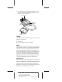
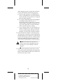
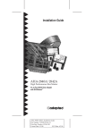
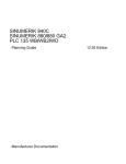
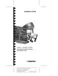
R
AA
AAAA
AA
AAAAAAAA
AAAAAAAA
AAAAAAAA
AAAAAAAA
AAAAAAAA
AAAAAAAA
AAAAAAAA
AAAAAAAA
AAAAAAAA
AAAAAAAA
AAAAAAAA
AAAAAAAA
AAAAAA
AA
AA
AA
APA-358A MiniSCSI-2 Installation Guide
AA
AA
AA
AA
AA
AA
Part
Number:
510809-00,
Rev.
A
AA
AA
AA
AA
AA
AA
Print
Spec
Number:
493477-00
AA
AA
AA
AA
AA
AA
Current
Date:
4/11/95
ECN
Date:
4/1195
AA
AA
AAAAAAAAAAAAAAAAAAAAAAAAAAAAAAAAAAAAAAAAAAAAAAAAAAAAAAA
AA
1 Getting Started
This guide explains how to install the APA-358A
MiniSCSI™-2 host adapter. The MiniSCSI-2 lets you
operate your SCSI devices through your computer’s
parallel port, while still using the port for your
printer. You can use the MiniSCSI-2 with an
enhanced parallel port (EPP), an extended capabilities
port that is EPP compliant (ECP/EPP), or a conventional parallel port.
Installation involves
■
■
Connecting your MiniSCSI-2 and SCSI devices to
your computer
Installing Adaptec EZ-SCSI™, the software needed
to support the MiniSCSI-2 and SCSI devices
Begin by reviewing the following checklist and hardware requirements. Then read the remaining sections
in the order presented. If you have problems during
installation, see Troubleshooting on page 8.
Checklist
Your MiniSCSI-2 package should contain the following items:
■
APA-358A MiniSCSI-2 host adapter
■
APA-358A MiniSCSI-2 Installation Guide
■
Adaptec EZ-SCSI diskettes and user’s guide
■
Registration cards (one each) for the MiniSCSI-2
and for Microsoft MSCDEX
If anything is missing, please contact your dealer.
Hardware Requirements
The MiniSCSI-2 is designed to be as universally
usable as possible, but your computer and SCSI
devices must meet a few requirements:
■
The computer must be an IBM or compatible AT
or PS/2 computer with a 100% IBM-compatible
BIOS. Operation with an incompatible BIOS may
be possible but is not guaranteed.
■
The computer’s parallel port must be standard—
that is, have a fully IBM-compatible hardware
design. For highest performance, the parallel port
must be EPP compliant.
1
A
AAAA
AAAA
AAAA
A
AAAAAAAA
AAAAAAAA
AAAAAAAA
AAAAAAAA
AAAAAAAA
AAAAAAAA
AAAAAAAA
AAAAAAAA
AAAAAAAA
AAAAAAAA
AAAAAAAA
AAAAAA
AA
A
AA
APA-358A MiniSCSI-2 Installation Guide
A
AA
A
AA
A
AA
Part
Number:
510809-00,
Rev.
A
A
AA
A
AA
A
AA
Print
Spec
Number:
493477-00
A
AA
A
AA
A
AA
Current
Date:
4/11/95
ECN
Date:
4/1195
A
AA
A
AAAAAAAAAAAAAAAAAAAAAAAAAAAAAAAAAAAAAAAAAAAAAAAAAAAAAA
AA
2 Understanding the MiniSCSI-2
Before you install the MiniSCSI-2, read this section to
learn about MiniSCSI-2 features, components, and
SCSI settings. You will need this information when
you install the MiniSCSI-2.
General Features
The MiniSCSI-2 lets you connect up to seven external
SCSI devices to your computer’s parallel port. You can
connect almost any type of SCSI device, including hard
disk drives, CD-ROM drives, removable-media drives,
and scanners. (For a list of supported devices, see
Adaptec EZ-SCSI User’s Guide.) Your printer and the
SCSI devices can operate simultaneously from the
same parallel port, with no performance degradation.
The MiniSCSI-2 is fully compatible with EPPcompliant ports. It is also backward compatible with
the non-EPP unidirectional and bidirectional parallel
ports found on many computer systems. There is no
need to specify whether the parallel port is EPP compliant—faster EPP transmission rates are automatic.
When not running in EPP mode, the port runs at standard parallel port (SPP) rates.
Note: Conventional parallel ports have data
transfer rates of 50 to 260 KBytes/sec. EPPcompliant ports reach up to 1 MByte/sec.
Adaptec EZ-SCSI automatically configures
the MiniSCSI-2 to the fastest speed possible.
Components
The MiniSCSI-2 has the following major components, illustrated in the figure that follows this list:
■
A 25-pin parallel port connector, which plugs into
the parallel port on your computer
■
A 50-pin high-density SCSI-2 connector, which
connects the MiniSCSI-2 to the SCSI devices
■
A printer passthrough connector, which connects
your printer to your computer through the
MiniSCSI-2, allowing the printer and SCSI devices
to use the parallel port simultaneously
2
A
AAAA
AAAA
AAAA
A
AAAAAAAA
AAAAAAAA
AAAAAAAA
AAAAAAAA
AAAAAAAA
AAAAAAAA
AAAAAAAA
AAAAAAAA
AAAAAAAA
AAAAAAAA
AAAAAAAA
AAAAAA
AA
A
AA
APA-358A MiniSCSI-2 Installation Guide
A
AA
A
AA
A
AA
Part
Number:
510809-00,
Rev.
A
A
AA
A
AA
A
AA
Print
Spec
Number:
493477-00
A
AA
A
AA
A
AA
Current
Date:
4/11/95
ECN
Date:
4/1195
A
AA
A
AAAAAAAAAAAAAAAAAAAAAAAAAAAAAAAAAAAAAAAAAAAAAAAAAAAAAA
AA
■
An LED light, which indicates whether a SCSI
device is supplying termination power (see Termination Power on page 4).
SCSI Connector
LED
Printer
Passthrough
Connector
Jack
for AC
Adapter
Parallel Port
Connector
Settings
The MiniSCSI-2 has the following factory-set SCSI ID
and SCSI termination:
■
SCSI ID: 7
■
SCSI termination: Always enabled
SCSI ID
SCSI devices connect to each other in one continuous
line called the SCSI bus. To prevent communication
conflicts, each device on the SCSI bus must have a
unique SCSI ID. Allowable IDs are 0 through 7. If
two devices attempt to access the SCSI bus simultaneously, the SCSI ID also determines which device
has priority: The device with the higher ID has the
higher priority. The ID for the MiniSCSI-2 is fixed at
7, giving it the highest priority on the SCSI bus.
SCSI Termination
For the SCSI bus to operate properly, the SCSI devices
at both ends of the bus must be electrically terminated.
This is accomplished by installing or enabling resistors,
called terminators, on the end devices. Because the
MiniSCSI-2 is always at one end of the SCSI bus, the
terminator on the MiniSCSI-2 is enabled.
3
A
AAAA
AAAA
AAAA
A
AAAAAAAA
AAAAAAAA
AAAAAAAA
AAAAAAAA
AAAAAAAA
AAAAAAAA
AAAAAAAA
AAAAAAAA
AAAAAAAA
AAAAAAAA
AAAAAAAA
AAAAAA
AA
A
AA
APA-358A MiniSCSI-2 Installation Guide
A
AA
A
AA
A
AA
Part
Number:
510809-00,
Rev.
A
A
AA
A
AA
A
AA
Print
Spec
Number:
493477-00
A
AA
A
AA
A
AA
Current
Date:
4/11/95
ECN
Date:
4/1195
A
AA
A
AAAAAAAAAAAAAAAAAAAAAAAAAAAAAAAAAAAAAAAAAAAAAAAAAAAAAA
AA
The device at the other end of the SCSI bus will be an
external SCSI device, such as an external hard disk
drive. External SCSI devices are normally terminated
by installing a terminator in the unused SCSI connector on the SCSI device (see the figure on page 5
for an example) or by setting jumpers or switches.
See your device documentation for details.
Termination Power
The SCSI bus must have termination power, a specific
voltage (5 volts) required by the terminators. Termination power may be available from one of the SCSI
devices attached to the MiniSCSI-2. To determine
whether a device provides termination power, check
the device documentation. You can also determine
this by connecting the device to the MiniSCSI-2, as
described in the next section, and checking the LED
on the MiniSCSI-2. If the LED lights after you turn on
the SCSI device, the device is providing termination
power (see step 10 on page 6).
The SCSI device that provides termination power
may be anywhere on the SCSI bus. Also, more than
one device can provide termination power—this
does not cause problems on the SCSI bus.
If none of the SCSI devices provides termination
power, you must obtain an AC adapter. You can
order the AC adapter from Adaptec at 800-442-7274.
3 Installing the MiniSCSI-2
Installing the MiniSCSI-2 involves plugging the
MiniSCSI-2 into the parallel port, then connecting the
MiniSCSI-2 to your SCSI devices and printer. Follow
the steps in this section, referring to the figure on
page 3 for connector locations.
WARNING: Turn OFF the computer, printer,
and SCSI devices when connecting or disconnecting the MiniSCSI-2.
1 Disconnect anything connected to the parallel
port you intend to use for the MiniSCSI-2. You
may use either LPT1, LPT2, or LPT3—the
4
A
AAAA
AAAA
AAAA
A
AAAAAAAA
AAAAAAAA
AAAAAAAA
AAAAAAAA
AAAAAAAA
AAAAAAAA
AAAAAAAA
AAAAAAAA
AAAAAAAA
AAAAAAAA
AAAAAAAA
AAAAAA
AA
A
AA
APA-358A MiniSCSI-2 Installation Guide
A
AA
A
AA
A
AA
Part
Number:
510809-00,
Rev.
A
A
AA
A
AA
A
AA
Print
Spec
Number:
493477-00
A
AA
A
AA
A
AA
Current
Date:
4/11/95
ECN
Date:
4/1195
A
AA
A
AAAAAAAAAAAAAAAAAAAAAAAAAAAAAAAAAAAAAAAAAAAAAAAAAAAAAA
AA
MiniSCSI-2 driver automatically detects which
port is used.
Note: If you use a copy-protection device
(commonly known as a dongle) on the parallel port, connect it to the printer passthrough
connector on the MiniSCSI-2. If this arrangement causes problems, relocate either the
dongle or the MiniSCSI-2 to a different parallel port.
2 Plug the MiniSCSI-2 parallel port connector into
the parallel port.
3 Plug the SCSI connector on the MiniSCSI-2 into
the first SCSI device.
Caution: The MiniSCSI-2 supports only single-ended SCSI devices. Do not connect differential SCSI devices to it (to determine the
device type, contact your vendor or see your
device documentation).
4 Connect up to six other SCSI devices by daisy
chaining one device to the next, with no branching
(see the following figure).
5 Make sure that each SCSI device has a unique
SCSI ID from 0 to 6. For instructions on changing
the ID for a device, see the device documentation.
5
A
AAAA
AAAA
AAAA
A
AAAAAAAA
AAAAAAAA
AAAAAAAA
AAAAAAAA
AAAAAAAA
AAAAAAAA
AAAAAAAA
AAAAAAAA
AAAAAAAA
AAAAAAAA
AAAAAAAA
AAAAAA
AA
A
AA
APA-358A MiniSCSI-2 Installation Guide
A
AA
A
AA
A
AA
Part
Number:
510809-00,
Rev.
A
A
AA
A
AA
A
AA
Print
Spec
Number:
493477-00
A
AA
A
AA
A
AA
Current
Date:
4/11/95
ECN
Date:
4/1195
A
AA
A
AAAAAAAAAAAAAAAAAAAAAAAAAAAAAAAAAAAAAAAAAAAAAAAAAAAAAA
AA
6 Terminate the last SCSI device attached to the
MiniSCSI-2, referring to the device documentation
for instructions.
7 Disable termination on all other SCSI devices
attached to the MiniSCSI-2, referring to the device
documentation for instructions.
8 To use a parallel printer with the MiniSCSI-2, connect a standard parallel printer cable to the
MiniSCSI-2 printer passthrough connector (see
the following figure). No special configuration or
switching is needed.
9 Check that the SCSI cables are still connected
securely. They may have loosened if you changed
jumper or switch settings on the devices.
10 Turn on the SCSI devices, then turn on the com-
6
A
AAAA
AAAA
AAAA
A
AAAAAAAA
AAAAAAAA
AAAAAAAA
AAAAAAAA
AAAAAAAA
AAAAAAAA
AAAAAAAA
AAAAAAAA
AAAAAAAA
AAAAAAAA
AAAAAAAA
AAAAAA
AA
A
AA
APA-358A MiniSCSI-2 Installation Guide
A
AA
A
AA
A
AA
Part
Number:
510809-00,
Rev.
A
A
AA
A
AA
A
AA
Print
Spec
Number:
493477-00
A
AA
A
AA
A
AA
Current
Date:
4/11/95
ECN
Date:
4/1195
A
AA
A
AAAAAAAAAAAAAAAAAAAAAAAAAAAAAAAAAAAAAAAAAAAAAAAAAAAAAA
AA
4 Installing Adaptec EZ-SCSI
To complete installation, install the Adaptec EZ-SCSI
software that accompanied the MiniSCSI-2. To do so,
follow the instructions in Adaptec EZ-SCSI User’s Guide.
The Adaptec EZ-SCSI Software
Adaptec EZ-SCSI provides the ASPI manager and
the device drivers the MiniSCSI-2 needs to operate
under DOS and Windows. The following table lists
the main Adaptec EZ-SCSI software used with the
MiniSCSI-2. For details, see Adaptec EZ-SCSI User’s
Guide.
Software
ma358.sys
aspidisk.sys
aspicd.sys
mscdex.exe
sjiix.sys
Description
The ASPI manager, which lets the device drivers
communicate with the MiniSCSI-2.
A device driver for SCSI disk devices, including
hard disk drives, Floptical drives, removable-media
drives, and disk drives larger than 1 GByte.
A device driver for CD-ROM drives.
The Microsoft CD-ROM extensions for DOS, which
are necessary to run CD-ROM drives.
A device driver for Hewlett-Packard scanners.
When you install Adaptec EZ-SCSI, it automatically
adds command lines to your config.sys file to load the
ASPI manager and the appropriate drivers for your
SCSI devices. It also modifies your autoexec.bat file to
include a command line for mscdex.exe.
ma358.sys Options
The command line for the ASPI manager, ma358.sys,
includes the following command options. You can
change these options by editing the command line in
the config.sys file (use a text editor program).
Note: The options described here supersede
those described in Appendix C of Adaptec
EZ-SCSI User’s Guide.
/pause
Makes your system pause after loading
ma358.sys at boot time, so you can read
the messages on the screen. After you read
them, press any key to resume booting.
7
A
AAAA
AAAA
AAAA
A
AAAAAAAA
AAAAAAAA
AAAAAAAA
AAAAAAAA
AAAAAAAA
AAAAAAAA
AAAAAAAA
AAAAAAAA
AAAAAAAA
AAAAAAAA
AAAAAAAA
AAAAAA
AA
A
AA
APA-358A MiniSCSI-2 Installation Guide
A
AA
A
AA
A
AA
Part
Number:
510809-00,
Rev.
A
A
AA
A
AA
A
AA
Print
Spec
Number:
493477-00
A
AA
A
AA
A
AA
Current
Date:
4/11/95
ECN
Date:
4/1195
A
AA
A
AAAAAAAAAAAAAAAAAAAAAAAAAAAAAAAAAAAAAAAAAAAAAAAAAAAAAA
AA
/Mnm
Determines the mode configuration and
the amount of time that the MiniSCSI-2
read and write cycles are delayed (parallel
ports on some computers require delays).
You must specify values for both n and m.
The n specifies the amount of delay. Allowable values for n are 0 through 7, with each
number representing a 125-nanosecond
(ns) increment. A value of 7, for example,
adds an 875 ns (7 x 125) delay to the cycles.
The default of 0 specifies no delays.
The m parameter determines the mode.
The allowable values are shown in the
following table.
Value of m
0
2
4
8
Meaning
Auto-detect mode (the default). Automatically
detects the type of port and configures the
MiniSCSI-2 for that port type.
Forces unidirectional mode.
Forces bidirectional mode.
Assumes EPP 8-bit bidirectional mode. For this
to work, the parallel port must be set for EPP
mode in the CMOS setup program. For instructions on using the CMOS setup program, see
your motherboard documentation.
If you change the ma358.sys options in the
config.sys file, turn the computer OFF and then ON
again to have the changes take effect. (Do not simply
reboot the computer using Ctrl-Alt-Del.)
5 Troubleshooting
If you have a problem during installation, first check
the items below. If you do not find the solution here,
read the remainder of this section. You should also
check the Troubleshooting section in Adaptec EZ-SCSI
User’s Guide.
■
Make sure all cables are properly connected.
■
Make sure the LED on the MiniSCSI-2 lights
when you turn ON the SCSI devices. If the LED on
the MiniSCSI-2 does not light, you do not have
8
A
AAAA
AAAA
AAAA
A
AAAAAAAA
AAAAAAAA
AAAAAAAA
AAAAAAAA
AAAAAAAA
AAAAAAAA
AAAAAAAA
AAAAAAAA
AAAAAAAA
AAAAAAAA
AAAAAAAA
AAAAAA
AA
A
AA
APA-358A MiniSCSI-2 Installation Guide
A
AA
A
AA
A
AA
Part
Number:
510809-00,
Rev.
A
A
AA
A
AA
A
AA
Print
Spec
Number:
493477-00
A
AA
A
AA
A
AA
Current
Date:
4/11/95
ECN
Date:
4/1195
A
AA
A
AAAAAAAAAAAAAAAAAAAAAAAAAAAAAAAAAAAAAAAAAAAAAAAAAAAAAA
AA
termination power and may need to obtain an AC
adapter (see Termination Power on page 4).
■
Make sure the SCSI bus is properly terminated.
■
Make sure all SCSI devices have unique SCSI IDs.
■
Make sure you are not trying to boot from a
device on the MiniSCSI-2. (A computer cannot
boot from a device connected to the parallel port.)
■
Make sure the parallel port address is 278h or 378h.
If it is 3BCh, the parallel port cannot be used in
EPP mode. In this case, change the port address to
278h or 378h, or change the /Mnm (mode configuration) option for ma358.sys to a non-EPP mode
(see ma358.sys Options on page 7).
Error Messages
The Adaptec EZ-SCSI drivers and ASPI manager display error messages if they detect a problem when
the computer boots. For information on most error
messages, see Adaptec EZ-SCSI User’s Guide. The following messages are not described in that user’s
guide.
No SCSI Host Adapter detected
The MiniSCSI-2 requires SCSI termination power to
operate. Turn ON the SCSI devices. If the LED on the
MiniSCSI-2 does not light, you do not have termination power. You may need to obtain an AC adapter
(see Termination Power on page 4).
Host Adapter detected. Warning: No devices respond on
this host adapter
If you receive this message, the mode setting for
ma358.sys is probably incorrect:
■
If you are using a mode other than Auto-detect,
try using Auto-detect (/Mnm, where m=0). This
should automatically configure the MiniSCSI-2 for
your parallel port type. To change to Auto-detect
mode, see ma358.sys Options on page 7.
■
If you are using Auto-detect mode (m=0), the
Auto-detect feature may not have properly
detected the port type. Try turning the computer
OFF and then ON again. If you still receive the
error message, try setting m to 2 or 4 (see
ma358.sys Options on page 7).
9
A
AAAA
AAAA
AAAA
A
AAAAAAAA
AAAAAAAA
AAAAAAAA
AAAAAAAA
AAAAAAAA
AAAAAAAA
AAAAAAAA
AAAAAAAA
AAAAAAAA
AAAAAAAA
AAAAAAAA
AAAAAA
AA
A
AA
APA-358A MiniSCSI-2 Installation Guide
A
AA
A
AA
A
AA
Part
Number:
510809-00,
Rev.
A
A
AA
A
AA
A
AA
Print
Spec
Number:
493477-00
A
AA
A
AA
A
AA
Current
Date:
4/11/95
ECN
Date:
4/1195
A
AA
A
AAAAAAAAAAAAAAAAAAAAAAAAAAAAAAAAAAAAAAAAAAAAAAAAAAAAAA
AA
■
If m is 8 (which tells ma358.sys to assume EPP
mode), the parallel port may not be EPP compliant. Check your computer documentation or contact your vendor to determine if the port is EPP
compliant. If it is not EPP compliant, change m to
0, 2, or 4 (see ma358.sys Options on page 7).
If the port is EPP compliant, you probably need to
configure it as an EPP port in the CMOS setup
program or else load a driver supplied by the manufacturer (see the manufacturer ’s instructions for
the proper procedure). If you need to load a
driver, load it before you load ma358.sys (you can
edit your config.sys file to include the load line
for the driver before the load line for ma358.sys).
Problems on Network Installations
If your computer is part of a network installation,
your printer port may be redirected to a network
printer. For instance, Novell NetWare software uses
the capture command for this purpose. If this is the
case, the software will not detect the hardware at
bootup. The simplest solution is to change your computer ’s parallel port hardware to LPT2 or LPT3, or
change your network redirection to a different port.
The MiniSCSI-2 Still Does Not Function
Try changing the mode configuration option in the
config.sys file:
1 In the command line for ma358.sys in your
config.sys file, change /Mnm so the value of n is 1.
For example, the line should look similar to
device=[path]ma358.sys /M1m
Note: For EPP ports that are not configured
automatically by Adaptec EZ-SCSI, place the
port in EPP mode (follow the manufacturer’s
instructions), leave n at 0 and set m to 8
(/M08) to force EPP mode, then follow the
tests in a through c. If you discover problems, modify the n value as explained in
steps 1 through 3.
10
A
AAAA
AAAA
AAAA
A
AAAAAAAA
AAAAAAAA
AAAAAAAA
AAAAAAAA
AAAAAAAA
AAAAAAAA
AAAAAAAA
AAAAAAAA
AAAAAAAA
AAAAAAAA
AAAAAAAA
AAAAAA
AA
A
AA
APA-358A MiniSCSI-2 Installation Guide
A
AA
A
AA
A
AA
Part
Number:
510809-00,
Rev.
A
A
AA
A
AA
A
AA
Print
Spec
Number:
493477-00
A
AA
A
AA
A
AA
Current
Date:
4/11/95
ECN
Date:
4/1195
A
AA
A
AAAAAAAAAAAAAAAAAAAAAAAAAAAAAAAAAAAAAAAAAAAAAAAAAAAAAA
AA
After setting the option, perform the tests below
to ensure the adapter is functioning properly:
a Perform a dir command on a hard disk drive
and/or a CD-ROM drive. Check for problems,
such as absurdly wrong numbers or corrupted
file names being reported.
b Try copying a large file (greater than 100 KBytes,
if possible) from the SCSI device to a
non-SCSI hard disk or floppy drive. Then use
the DOS comp command to compare the new
copy to the original file. Check for problems,
such as the file comparison failing.
c Copy a large file from your non-SCSI drive to
a SCSI rewritable device. Again, compare the
two files with the comp command. Check for
problems, such as the file comparison failing.
2 If your MiniSCSI-2 still does not function properly, repeat step 1 with other n values (2 through 7)
until the adapter works. The idea is to optimize performance by selecting the lowest n value that works
with your parallel port; typically the value of 2
works with most parallel ports with this problem.
Caution: If the MiniSCSI-2 still does not
work, it may not be compatible with your
parallel port. Contact Adaptec technical
support.
3 If you share the MiniSCSI-2 with other systems,
set up each system individually for proper performance with the MiniSCSI-2. Be sure to follow the
instructions in steps 1 and 2.
11
A
AAAA
AAAA
AAAA
A
AAAAAAAA
AAAAAAAA
AAAAAAAA
AAAAAAAA
AAAAAAAA
AAAAAAAA
AAAAAAAA
AAAAAAAA
AAAAAAAA
AAAAAAAA
AAAAAAAA
AAAAAA
AA
A
AA
APA-358A MiniSCSI-2 Installation Guide
A
AA
A
AA
A
AA
Part
Number:
510809-00,
Rev.
A
A
AA
A
AA
A
AA
Print
Spec
Number:
493477-00
A
AA
A
AA
A
AA
Current
Date:
4/11/95
ECN
Date:
4/1195
A
AA
A
AAAAAAAAAAAAAAAAAAAAAAAAAAAAAAAAAAAAAAAAAAAAAAAAAAAAAA
AA
6 Adaptec Customer Support Services
If you have questions about installing or using the
host adapter, check this install guide first—you will
find answers to most of your questions here. If you
need further assistance, please contact us. We offer
the following support and information services:
■
For technical support (answers to technical questions, information about the Adaptec BBS, FTP and WWW Servers, and
access to the Interactive Fax system), call 800-959-SCSI (7274)
or 408-945-2550, 24 hours a day, 7 days a week. To speak with a
product support representative, call 408-934-SCSI (7274), M–F:
6:00 a.m. to 5:00 p.m., Pacific Time.
■
For sales information, call 800-959-SCSI (7274) or 408-945-2550,
M–F: 6:00 a.m. to 5:00 p.m., Pacific Time.
■
The Adaptec Electronic Bulletin Board Service (BBS) provides
information on software upgrades, answers to common questions, and other topics. The BBS is available 24 hours a day, 7
days a week, at 408-945-7727; 1200/2400/9600/14,400/28,800
baud, 8 data bits, 1 stop bit, no parity.
■
The Adaptec FTP and WWW Servers and CompuServe provide information on software upgrades, product literature,
answers to common questions, and other topics. The FTP and
WWW Servers are available from the Internet 24 hours a day, 7
days a week, at ftp.adaptec.com and http://www.adaptec.com.
On CompuServe, type go adaptec.
■
The Adaptec Interactive Fax system provides answers to common questions, product literature, and current information
about Adaptec products and services. The Adaptec Interactive
Fax system is available 23 hours a day, 7 days a week. The Fax
system is out of service 1 hour each day. You can call this service directly at 408-957-7150.
■
To order Adaptec software and SCSI cables, call 800-442-SCSI
(7274) or 408-957-SCSI (7274), M–F: 6:00 a.m. to 5:00 p.m.,
Pacific Time.
■
To request additional documentation for Adaptec products,
call 800-934-2766 or 510-732-3829, M–F: 6:00 a.m. to 5:00 p.m.,
Pacific Time.
12
A
AAAA
AAAA
AAAA
A
AAAAAAAA
AAAAAAAA
AAAAAAAA
AAAAAAAA
AAAAAAAA
AAAAAAAA
AAAAAAAA
AAAAAAAA
AAAAAAAA
AAAAAAAA
AAAAAAAA
AAAAAA
AA
A
AA
APA-358A MiniSCSI-2 Installation Guide
A
AA
A
AA
A
AA
Part
Number:
510809-00,
Rev.
A
A
AA
A
AA
A
AA
Print
Spec
Number:
493477-00
A
AA
A
AA
A
AA
Current
Date:
4/11/95
ECN
Date:
4/1195
A
AA
A
AAAAAAAAAAAAAAAAAAAAAAAAAAAAAAAAAAAAAAAAAAAAAAAAAAAAAA
AA
FCC Compliance Statement
NOTE: This equipment has been tested and found to comply with the limits
for a Class B digital device, pursuant to Part 15 of the FCC rules. These limits are designed to provide reasonable protection against harmful interference in residential installations. This equipment generates, uses, and can
radiate radio frequency energy, and if not installed and used in accordance
with the instructions, may cause harmful interference to radio communications. However, there is no guarantee that interference will not occur in a
particular installation.
If this equipment does cause interference to radio or television equipment
reception, which can be determined by turning the equipment off and on,
the user is encouraged to try to correct the interference by one or more of the
following measures:
•
•
•
Reorient or relocate the receiving antenna
Move the equipment away from the receiver
Plug the equipment into an outlet on a circuit different from that to
which the receiver is powered
• If necessary, the user should consult the dealer or an experienced radio/
television technician for additional suggestions
CAUTION: Only equipment certified to comply with Class B (computer
input/output devices, terminals, printers, etc.) should be attached to this
equipment, and must have shielded interface cables.
Finally, any changes or modifications to the equipment by the user not
expressly approved by the grantee or manufacturer could void the user ’s
authority to operate such equipment.
Each host adapter is equipped with an FCC compliance label that shows
only the FCC identification number. The full text of the associated label
follows:
This device complies with part 15 of the FCC rules. Operation is subject to
the following two conditions: (1) this device may not cause harmful interference and (2) this device must accept any interference received, including
interference that may cause undesired operation.
European Community Mark
This adapter meets CE mark requirements.
Adaptec, Inc.
691 South Milpitas Blvd.
Milpitas, CA 95035
Copyright © 1995, Adaptec, Inc. All rights reserved. Adaptec, the
Adaptec logo, and EZ-SCSI are trademarks of Adaptec, Inc.,
which may be registered in some jurisdictions. MiniSCSI is a
trademark of Trantor Systems Limited, an Adaptec company. All
other trademarks are owned by their respective owners.
Printed in Singapore
Stock No.: 510809-00, Rev. A JK 4/95
Information subject to change without notice.
13
A
AAAA
AAAA
AAAA
A
AAAAAAAA
AAAAAAAA
AAAAAAAA
AAAAAAAA
AAAAAAAA
AAAAAAAA
AAAAAAAA
AAAAAAAA
AAAAAAAA
AAAAAAAA
AAAAAAAA
AAAAAA
AA
A
AA
APA-358A MiniSCSI-2 Installation Guide
A
AA
A
AA
A
AA
Part
Number:
510809-00,
Rev.
A
A
AA
A
AA
A
AA
Print
Spec
Number:
493477-00
A
AA
A
AA
A
AA
Current
Date:
4/11/95
ECN
Date:
4/1195
A
AA
A
AAAAAAAAAAAAAAAAAAAAAAAAAAAAAAAAAAAAAAAAAAAAAAAAAAAAAA
AA