1
MaXiO XD
EX8000
INDEX
1. Introduction.................................................................................................................................. 2
1.1 Key Features........................................................................................................................... 2
1.2 Safety Instructions.................................................................................................................. 2
2. Description of EX8000 ................................................................................................................. 3
2.1 Front Channel Section ............................................................................................................ 3
2.2 Power Section......................................................................................................................... 4
2.3 Clock & Control ..................................................................................................................... 4
2.4 Analog Outputs & Inserts....................................................................................................... 5
2.5 Digital I/O............................................................................................................................... 6
3. Usage of EX8000 .......................................................................................................................... 7
3.1 Control Modes........................................................................................................................ 7
3.1.1 E.D.I Control Mode .......................................................................................................... 7
3.1.2 Standalone Mode .............................................................................................................. 7
3.1.3 Reset Internal Configuration............................................................................................. 7
3.2 Audio Routing ........................................................................................................................ 7
3.2.1 Audio Routing Mode selection ......................................................................................... 7
3.2.2 [MODE 1] AES/EBU to analog / analog to AES/EBU .................................................... 8
3.2.3 [MODE 2] S/PDIF to analog / analog to S/PDIF ............................................................. 9
3.2.4 [MODE 3] analog to ADAT and AES/EBU..................................................................... 9
3.2.5 [MODE 4] AES/EBU to ADAT / ADAT to AES/EBU ................................................. 10
3.2.6 [MODE 5] ADAT to analog / analog to ADAT ............................................................. 10
3.2.7 [MODE 6] ADAT to analog / analog to ADAT (with S/MUX enabled) ....................... 11
3.2.8 Channel Mapping............................................................................................................ 11
3.3 System Clock........................................................................................................................ 12
3.3.1 System Clock Source ...................................................................................................... 12
3.3.2 Internal Clock.................................................................................................................. 13
3.3.3 External Clock (Word Clock) ......................................................................................... 13
3.3.4 Digital Input Clock ......................................................................................................... 13
3.3.5 E.D.I Clock ..................................................................................................................... 14
4. Technical Specifications ............................................................................................................ 15
END USER WARRANTY ............................................................................................................ 16
v1 March 2005
1
MaXiO XD
EX8000
1. Introduction
Thank you for choosing the ESI EX8000, part of the MaXiO XD system.
EX8000 is a high performance 24-bit, 192 kHz AD/DA converter that features 8 balanced inputs
with microphone preamps, XLR/TRS combo connectors and 10 step LED metering lights for each
input channel. EX8000 also provides 8 analog output channels, multi-channel AES/EBU and
S/PDIF digital I/O, ADAT I/O and a headphone output for monitoring.
You can use EX8000 either as a very powerful standalone device or in combination with the
MaXiO PCI host card as a high-end multi-channel recording solution for the PC.
1.1 Key Features
·
·
·
·
·
·
·
·
·
·
·
·
·
·
·
E.D.I Connector
high-end quality 24-bit / 192 kHz ADC with 123dB(a) dynamic range
high-end quality 24-bit / 192 kHz DAC with 120dB(a) dynamic range
8 balanced analog inputs with combo (XLR / TRS) connectors
high precision & ultra low noise 'XD-PRE' microphone preamplifier (-135.5dBu) on each analog
input channel with support for +48V phantom power
Mic/Line selection switch and gain control for each analog input channel
8 inserts (one for each analog input channel) with 1/4" connectors
8 balanced analog outputs with XLR connectors (+4dBu)
8 balanced/unbalanced analog outputs with TRS connectors (-10dBV)
headphone amplifier with volume control
8 channel digital I/O in AES/EBU (XLR connectors) and coaxial S/PDIF (RCA connectors)
format, supporting up to 24-bit / 192 kHz
8 channel ADAT optical digital I/O with S/MUX support
10 step LED level meters on front panel for all channels (input and output)
supported sample rates: 44.1, 48, 88.2, 96, 176.4 and 192 kHz
Word Clock Input: Fs / 256*Fs (via BNC connector)
1.2 Safety Instructions
Caution: To reduce the risk of electrical shock, do not remove the cover of this unit. Please refer
servicing to qualified personnel only.
Warning: Do not expose this unit to rain or moisture.
Retain Instructions: Please retain all safety and operating instructions for future reference.
Heat: The unit should be placed away from other heat sources such as heaters, radiators, ovens or
other studio equipment such as power amplifiers that produce heat.
Periods of inactivity: The power cord of the unit should be unplugged from the outlet when left
unused for a long period of time.
2
MaXiO XD
EX8000
2. Description of EX8000
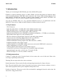
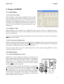
2.1 Front Channel Section
1
Analog Balanced XLR / TRS (Combo) Input Connector
EX8000 provides 8 combo connectors (XLR and 1/4" TRS) on
the front panel that are used as balanced analog inputs for line
level signals and microphone connection (via XLR).
2
4
2
Microphone Input Selection Switch
Every input channel can be used for line level or microphone
signals. When this switch is enabled, a microphone can be
connected via XLR. In this case phantom power is supplied
(when enabled, check no. 7). When the switch is not enabled, the
XLR and TRS inputs are used for balanced line level signals.
3
Input Gain Control
Controls the amount gain applied to the input signal from the
XLR or TRS connector of specific channel. Microphone signals
can be amplified with 48dB maximum, line level signals with up
to 30dB.
4
1
3
Analog Input / Output Level Meter
The two level meters indicate the signal level for the analog inputs and outputs. The level meter
on the left shows the input signal; the level meter on the right shows the output signal of the
corresponding channel. A range from 0dB to 60dB in 10 dB-steps is displayed.
3
MaXiO XD
EX8000
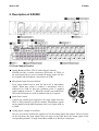
2.2 Power Section
5
Power Indicator LED
5
6
Power Switch
7
Phantom Power Switch
6
+48V DC phantom power (for balanced condenser microphones) will be
supplied via every XLR input connector when this button is enabled.
Note that this affects only those input channels that are set to receive
microphone signals (check no. 2).
7
Before you turn on the phantom power switch, you must make sure to connect your microphones
to the XLR inputs (with balanced cables).
· After you have turned on the phantom power switch, you should not connect or disconnect a
microphone to any of the input connectors.
·
!
CAUTION
22
22
AC IN
EX8000 needs external AC power. It supports 100~240V AC (free voltage). There
is a spare fuse (5X20mm Glass Fuse) below the connector.
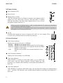
2.3 Clock & Control
9
Clock Source Indicator
Displays the current clock source of EX8000:
- Internal: EX8000 uses its internal clock.
- External: EX8000 works with the clock from the Word Clock input.
- Digital In: EX8000 works with the clock supplied from the AES/EBU,
S/PDIF or ADAT input.
- E.D.I:
EX8000 works with the clock from the MaXiO PCI host
card.
10
12
Clock Select Button 1
When EX8000 is working in stand alone mode, you can choose the
clock source with this button (Internal, External, Digital In). This
function is not available when EX8000 is connected to the MaXiO PCI
host card.
12
11
Clock Frequency Indicator
Displays the current sample rate of EX8000.
11
9
10
Clock Select Button 2
When EX8000 is working in stand alone mode, you can choose the sample rate with this button
(44.1 ~ 192 kHz). This function is not available when EX8000 is connected to the MaXiO PCI
host card.
4
MaXiO XD
21
EX8000
Word Clock Input
The Word Clock input allows you to synchronize EX8000 with other devices. When
EX8000 is connected to a Word Clock source, EX8000 will synchronize to it.
2.4 Analog Outputs & Inserts
8
Headphone
You can monitor the playback signal from output 1, 2 through the headphone
output. The output level can be adjusted with the pot.
14
Inserts
The inserts allow you to use the microphone preamps of EX8000 for incoming signals, then run
the signal through external hardware effects before the AD-converter processes the signal. In
order to use the inserts, you typically need a so-called "insert-cable"
with a 1/4" TRS connector on one and two 1/4" mono connectors on
the two other ends. Here is a description of the insert connector:
- Tip: return signal (input from effect processor)
- Ring: send (output to effect processor)
- Sleeve: common ground
15
Analog Balanced TRS Output Connectors
EX8000 has 8 balanced/unbalanced analog outputs (-10dBV) with TRS connectors.
16
Analog Balanced XLR Output Connectors
EX8000 has 8 balanced analog outputs (+4dBu) with XLR connectors.
5
MaXiO XD
EX8000
2.5 Digital I/O
17
E.D.I Connector
E.D.I Connector IN: connection to MaXiO PCI (with a standard IEEE1394 cable).
E.D.I Connector THRU: this connector is reversed for future expansion.
18
ADAT Optical Input / Output
EX8000 has 8 channel ADAT optical I/O connectors. You can connect EX8000
to devices such as digital mixers or ADAT multichannel reorders equipped with
optical ADAT connectors. One ADAT cable transfers 8 channels with max. 48
kHz. EX8000 also supports different S/MUX modes to transfer signals with 96
kHz and above (S/MUX 2: 96 kHz, 4 channels / S/MUX 4: 192 kHz, 2
channels).
19
Digital S/PDIF (RCA) Input / Output
EX8000 has 4 S/PDIF inputs and 4 S/PDIF outputs (RCA) for coaxial
digital connection.
20
AES/EBU (XLR) Input / Output
EX8000 has 4 AES/EBU inputs and 4 AES/EBU outputs (XLR) for balanced digital connection.
6
MaXiO XD
EX8000
3. Usage of EX8000
3.1 Control Modes
3.1.1 E.D.I Control Mode
When EX8000 is connected to the MaXiO PCI host card,
it is controlled via the E.D.I connection from the PC.
EX8000 automatically detects if it is connected to a PC
when power is switched on. In that case, it can only be
controlled via the MaXiO XD Control Panel software on
your PC. Check the MaXiO XD system manual for more
information.
3.1.2 Standalone Mode
When EX8000 is not connected to a MaXiO PCI host card, it works as a standalone device.
EX8000 automatically switches to this standalone mode when there is no active E.D.I signal when
power is switched on.
You can set up the internal audio routing and the system clock with the two clock selection buttons
( 11 12 ) on the front panel.
3.1.3 Reset Internal Configuration
EX8000 will automatically keep the last configuration in standalone mode. If you want the reset this
value, press the first clock selection button ( 11 ) when all lights on the front panel are on during the
initialisation of EX8000 after power has been switched on.
The system clock will be set to the default (internal, 44.1 kHz); audio routing [MODE 1] will be
selected as default (see below).
3.2 Audio Routing
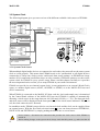
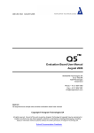
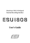
3.2.1 Audio Routing Mode selection
EX8000 has various digital and analog I/O connectors. In
E.D.I Control Mode, the audio signal routing is controlled the
MaXiO XD Control Panel software on your PC. In standalone
mode, there are 6 different audio routing mode presets
available that can be selected via the two clock selection
buttons ( 11 12 ) on the front panel.
Push these buttons simultaneously
[MODE 6]
[MODE 5]
[MODE 4]
To change the audio routing when EX8000 is in standalone
mode, you need to push the two clock selection buttons ( 11
12
) simultaneously. The current mode ([MODE 1] to [MODE
6]) is displayed via the output level meter display of channel
8. Please refer to the picture on the right to see which LED is
used to display which mode. A description of each different
mode follows in the next sections.
[MODE 3]
[MODE 2]
[MODE 1]
7
MaXiO XD
EX8000
Please verify your I/O connections before you change the audio routing.
· Please temporarily turn off your amplifier or active monitor speakers when you change the audio
routing.
·
!
CAUTION
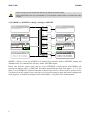
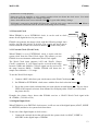
3.2.2 [MODE 1] AES/EBU to analog / analog to AES/EBU
E.D.I
E.D.I IN
ANALOG
ADAT
8CH 24-bit/192kHz
E.D.I
DIGITAL IN
4 XLR In
4 RCA In
E.D.I OUT
DIGITAL
8CH 24-bit/192kHz
DIGITAL
~ Professional
{ Consumer
ANALOG
ADAT
DIGITAL OUT
ANALOG
~ Professional
{ Consumer
E.D.I
ANALOG IN
DIGITAL
8 XLR / TRS IN
ADC
MIC / LINE, GAIN
ADAT OPTICAL IN
~ Normal : 8CH 24-bit/48kHz
{ S/MUX 2 : 4CH 24-bit/96kHz
{ S/MUX 4 : 2CH 24-bit/192kHz
ANALOG
ADAT
ANALOG OUT
DIGITAL
ANALOG
ADAT
DAC
E.D.I
DIGITAL
4 XLR Out
4 RCA Out
8 XLR balanced OUT
8 TRS balanced OUT
ADAT OPTICAL OUT
DIGITAL
~ Normal : 8CH 24-bit/48kHz
{ S/MUX 2 : 4CH 24-bit/96kHz
{ S/MUX 4 : 2CH 24-bit/192kHz
[MODE 1] allows you to use EX8000 as 8 channel AD converter with 4 AES/EBU outputs and
simultaneously as 8 channel DA converter with 4 AES/EBU inputs.
Please note that the system clock can be set to INTERNAL (which means that EX8000 will
generate the master clock), to DIGITAL IN (which means that the clock from input 1, 2, 3 or 4 is
used) or to EXTERNAL (which means that a Word Clock source will be used as system clock).
You must set up the system clock correctly for your specific setup to make this audio routing mode
work properly. A detailed description can be found under 3.3 System Clock in this manual.
8
MaXiO XD
EX8000
3.2.3 [MODE 2] S/PDIF to analog / analog to S/PDIF
E.D.I
E.D.I IN
ANALOG
ADAT
8CH 24-bit/192kHz
E.D.I
DIGITAL IN
4 XLR In
4 RCA In
E.D.I OUT
DIGITAL
8CH 24-bit/192kHz
DIGITAL
{ Professional
~ Consumer
ANALOG
ADAT
DIGITAL OUT
ANALOG
{ Professional
~ Consumer
E.D.I
ANALOG IN
DIGITAL
8 XLR / TRS IN
ADC
MIC / LINE, GAIN
ANALOG
ADAT
ANALOG OUT
DIGITAL
~ Normal : 8CH 24-bit/48kHz
{ S/MUX 2 : 4CH 24-bit/96kHz
{ S/MUX 4 : 2CH 24-bit/192kHz
DIGITAL
ANALOG
ADAT
DAC
E.D.I
ADAT OPTICAL IN
4 XLR Out
4 RCA Out
8 XLR balanced OUT
8 TRS balanced OUT
ADAT OPTICAL OUT
DIGITAL
~ Normal : 8CH 24-bit/48kHz
{ S/MUX 2 : 4CH 24-bit/96kHz
{ S/MUX 4 : 2CH 24-bit/192kHz
[MODE 2] allows you to use EX8000 as 8 channel AD converter with 4 S/PDIF outputs and
simultaneously as 8 channel DA converter with 4 S/PDIF inputs. This is similar to [MODE 1]
although the digital I/O is an S/PDIF consumer signal in [MODE 2] while in [MODE 1] it is a
professional AES/EBU signal.
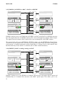
3.2.4 [MODE 3] analog to ADAT and AES/EBU
E.D.I
E.D.I IN
ANALOG
ADAT
8CH 24-bit/192kHz
E.D.I
DIGITAL IN
4 XLR In
4 RCA In
E.D.I OUT
DIGITAL
8CH 24-bit/192kHz
DIGITAL
~ Professional
{ Consumer
ANALOG
ADAT
DIGITAL OUT
ANALOG
~ Professional
{ Consumer
E.D.I
ANALOG IN
DIGITAL
8 XLR / TRS IN
ADC
MIC / LINE, GAIN
ADAT OPTICAL IN
~ Normal : 8CH 24-bit/48kHz
{ S/MUX 2 : 4CH 24-bit/96kHz
{ S/MUX 4 : 2CH 24-bit/192kHz
ANALOG
ADAT
ANALOG OUT
DIGITAL
ANALOG
ADAT
DAC
E.D.I
DIGITAL
4 XLR Out
4 RCA Out
8 XLR balanced OUT
8 TRS balanced OUT
ADAT OPTICAL OUT
ANALOG
~ Normal : 8CH 24-bit/48kHz
{ S/MUX 2 : 4CH 24-bit/96kHz
{ S/MUX 4 : 2CH 24-bit/192kHz
[MODE 3] equals [MODE 1] with the difference that the ADAT optical output will send out an 8
channel signal from the AD converters in addition. This allows you to use EX8000 as 8-channel
ADC with microphone preamps and inserts for devices with optical ADAT input.
9
MaXiO XD
EX8000
3.2.5 [MODE 4] AES/EBU to ADAT / ADAT to AES/EBU
E.D.I
E.D.I IN
ANALOG
ADAT
8CH 24-bit/192kHz
E.D.I
DIGITAL IN
4 XLR In
4 RCA In
E.D.I OUT
DIGITAL
8CH 24-bit/192kHz
DIGITAL
~ Professional
{ Consumer
ANALOG
ADAT
DIGITAL OUT
ADAT
~ Professional
{ Consumer
E.D.I
ANALOG IN
DIGITAL
8 XLR / TRS IN
ADC
MIC / LINE, GAIN
ANALOG
ADAT
ANALOG OUT
DIGITAL
~ Normal : 8CH 24-bit/48kHz
{ S/MUX 2 : 4CH 24-bit/96kHz
{ S/MUX 4 : 2CH 24-bit/192kHz
DIGITAL
ANALOG
ADAT
DAC
E.D.I
ADAT OPTICAL IN
4 XLR Out
4 RCA Out
8 XLR balanced OUT
8 TRS balanced OUT
ADAT OPTICAL OUT
DIGITAL
~ Normal : 8CH 24-bit/48kHz
{ S/MUX 2 : 4CH 24-bit/96kHz
{ S/MUX 4 : 2CH 24-bit/192kHz
[MODE 4] allows you to use EX8000 has AES/EBU to ADAT and ADAT to AES/EBU converter
unit. The signals from the 4 AES/EBU inputs will be sent out through the 8 channel ADAT output.
The signal from the 8 channel ADAT input will be sent out through the 4 AES/EBU outputs.
The system clock can be set to INTERNAL, DIGITAL (input 1~4) and EXTERNAL (Word Clock).
You must set up the system clock correctly for your specific setup to make this audio routing mode
work properly. A detailed description can be found under 3.3 System Clock in this manual. Note
that this mode only works with 44.1 or 48 kHz (due to ADAT format limitations).
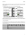
3.2.6 [MODE 5] ADAT to analog / analog to ADAT
E.D.I
E.D.I IN
ANALOG
ADAT
8CH 24-bit/192kHz
E.D.I
DIGITAL IN
4 XLR In
4 RCA In
E.D.I OUT
DIGITAL
8CH 24-bit/192kHz
DIGITAL
~ Professional
{ Consumer
ANALOG
ADAT
DIGITAL OUT
ADAT
~ Professional
{ Consumer
E.D.I
ANALOG IN
DIGITAL
8 XLR / TRS IN
ADC
MIC / LINE, GAIN
ADAT OPTICAL IN
~ Normal : 8CH 24-bit/48kHz
{ S/MUX 2 : 4CH 24-bit/96kHz
{ S/MUX 4 : 2CH 24-bit/192kHz
ANALOG
ADAT
ANALOG OUT
ADAT
ANALOG
ADAT
DAC
E.D.I
DIGITAL
4 XLR Out
4 RCA Out
8 XLR balanced OUT
8 TRS balanced OUT
ADAT OPTICAL OUT
ANALOG
~ Normal : 8CH 24-bit/48kHz
{ S/MUX 2 : 4CH 24-bit/96kHz
{ S/MUX 4 : 2CH 24-bit/192kHz
[MODE 5] allows you to use EX8000 as 8 channel AD converter with optical ADAT output and
simultaneously as 8 channel DA converter with ADAT optical input. This allows you to use
10
MaXiO XD
EX8000
EX8000 as standalone AD and DA converter for any ADAT compatible devices such as digital
mixers or ADAT multitrack recorders. [MODE 5] only works with 44.1 or 48 kHz (due to ADAT
format limitations).
3.2.7 [MODE 6] ADAT to analog / analog to ADAT (with S/MUX enabled)
E.D.I
E.D.I IN
ANALOG
ADAT
8CH 24-bit/192kHz
E.D.I
DIGITAL IN
4 XLR In
4 RCA In
E.D.I OUT
DIGITAL
8CH 24-bit/192kHz
DIGITAL OUT
DIGITAL
ADAT
ANALOG
ADAT
~ Professional
{ Consumer
~ Professional
{ Consumer
E.D.I
ANALOG IN
ANALOG OUT
DIGITAL
8 XLR / TRS IN
ADC
MIC / LINE, GAIN
ADAT
ANALOG
ADAT
DAC
E.D.I
ADAT OPTICAL IN
8 XLR balanced OUT
8 TRS balanced OUT
ADAT OPTICAL OUT
DIGITAL
{ Normal : 8CH 24-bit/48kHz
~ S/MUX 2 : 4CH 24-bit/96kHz
{ S/MUX 4 : 2CH 24-bit/192kHz
4 XLR Out
4 RCA Out
ANALOG
ANALOG
ADAT
{ Normal : 8CH 24-bit/48kHz
~ S/MUX 2 : 4CH 24-bit/96kHz
{ S/MUX 4 : 2CH 24-bit/192kHz
[MODE 6] equals [MODE 5] with the difference that S/MUX is enabled. This means that only 4
instead of 8 channels are transferred, but the supported sample rates are now doubled. [MODE 6]
only works with 88.2 kHz or 96 kHz.
3.2.8 Channel Mapping
The following table shows the mapping of the I/O channel assignment of EX8000. This is
especially important when you work with S/MUX enabled. Note that S/MUX 4 (192 kHz) only can
be used when EX8000 is connected to the MaXiO PCI host card. In the table, E.D.I refers to the
connection to the PCI card.
Analog I/O
CH 1
CH 2
CH 3
CH 4
CH 5
CH 6
CH 7
CH 8
Digital I/O
1L
1R
2L
2R
3L
3R
4L
4R
ADAT I/O
ADAT –1
ADAT - 2
ADAT - 3
ADAT - 4
ADAT - 5
ADAT - 6
ADAT - 7
ADAT - 8
ADAT S/MUX 2 (96)
S/MUX –1
S/MUX -2
S/MUX -3
S/MUX -4
ADAT S/MUX 4 (192)
S/MUX –1
S/MUX - 2
E.D.I –1
E.D.I - 2
E.D.I - 3
E.D.I - 4
E.D.I - 5
E.D.I - 6
E.D.I - 7
E.D.I - 8
E.D.I
11
MaXiO XD
EX8000
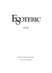
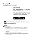
3.3 System Clock
The following diagram gives you an overview of the different available clock sources of EX8000.
INTERNAL
192.0kHz
176.4kHz
96.0kHz
88.2kHz
48.0kHz
44.1kHz
INTERNAL
EXTERNAL
DIGITAL
E.D.I
EXTERNAL
44.1 ~ 192kHz
256FS
FS
Clock Source Select
Clock Freq. / Sub Clock
DIGITAL IN
ADAT In
Digital In 4
Digital In 3
Digital In 2
Digital In 1
E.D.I Clock
From PCI Host Card Clock
44.1 ~ 192 kHz
3.3.1 System Clock Source
When multiple digital audio devices are connected to each other, they must all use the same system
clock to work properly. This means that EX8000 needs to be synchronised to all digital devices
connected to it. Drop outs, clicks or noise could result from wrong settings. As EX8000 has a huge
number of I/O connection possibilities, there are also a number of different options to set the correct
system clock for EX8000 in every specific setup. Please read this chapter carefully as it provides
the most important basics to allow you to setup EX8000 in your studio environment.
EX8000 can provide its own internal system clock, it can synchronise to an external (Word Clock)
source, to another digital source (ADAT, AES/EBU or S/PDIF) or to the MaXiO PCI host card
(E.D.I connection).
When EX8000 is connected to the MaXiO PCI host card, the clock and sample rate is determined
by the Control Panel software of the MaXiO PCI host card. EX8000 is capable of automatically
detecting a clock source in the range between 44.1 kHz and 192 kHz (+/- 3%). The detected clock
and clock source will be displayed on the front panel ( 10 ). If the clock source indicator LED ( 9 ) is
red, the clock cannot be used / detected.
In standalone mode, EX8000 can provide its own internal clock and the clock can be supplied from
an external source. With the first clock selection button ( 11 ) you can choose between INTERNAL,
DIGITAL IN and EXTERNAL by simply pushing the button one or several times.
Never connect / disconnect the connection that provides the clock source while EX8000 is
turned on.
· Before making changes to the system clock, always check the full system; e.g. make sure that all
·
!
CAUTION
12
MaXiO XD
EX8000
used devices are setup properly.
· Please turn off your amplifier or active monitor speakers when you change the clock source. You might
hear noise during the change or if a setting is incorrect.
· Please check that the clock source indicator LED ( 9 ) is green after making a change.
· If EX8000 is connected to the MaXiO PCI host card, verify the clock source indicator LED ( 9 ). When it
is not green, the connection to the PC and the clock settings are not working.
3.3.2 Internal Clock
When EX8000 is set to INTERNAL clock, it can be used as clock
master for all digital devices in your setup.
Clock Freq.
EX8000 can generate the master clock with the following sample rates
in kHz: 44.1/48.0/88.2/96.0/176.4/192.0. The sample rate itself can be
selected with the second clock selection button ( 12 ) on the front panel.
3.3.3 External Clock (Word Clock)
When EX8000 is set to EXTERNAL clock, it works with the
system clock from the Word Clock input. This allows you use
EX8000 in an environment with master Word Clock signal.
The Word Clock input supports 1xFS and 256xFs ("Super
Clock") resolutions. A 1xFs signal can be received in the range
between 32kHz and 200kHz, a 256xFs signal can be received in
the range between 8MHz ~ 50MHz. EX8000 will detect the
sample rate within the +/-3% range.
Sub Clock Select
256 Fs
Fs
To use the Word Clock input...
1. Connect a BNC cable from your clock source to the Word Clock input ( 21 ).
2. Set EX8000 to EXTERNAL clock source with the first clock selection button ( 11 ).
3. Set up the system clock resolution that you want with the second button ( 12 ). The two lower
LEDs of the output level meter from channel 8 will display either 256xFS or 1xFS (check
the picture above).
Example: the picture above shows that EX8000 receives a 256xFS Word Clock signal with
49.152MHz (=192 kHz x 256).
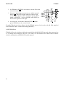
3.3.4 Digital Input Clock
When EX8000 is set to DIGITAL clock source, it will use one of the digital inputs (ADAT, S/PDIF
or AES/EBU) and derive its system clock from there.
To use one of the digital inputs as clock source...
1. Connect the external device that will provide the system clock via ADAT, S/PDIF or
AES/EBU to the digital input of EX8000.
13
MaXiO XD
EX8000
2. Set EX8000 to DIGITAL clock source with the first clock
selection button ( 11 ).
3. Select the digital input you want to use with the second
button ( 12 ). The LEDs of the output level meter from
channel 8 will display ADAT IN (for the optical ADAT
input), or DIGITAL 1~4 (for AES/EBU and S/PDIF) as
shown on the picture on the right.
4. As soon as the clock source indicator LED (
green, EX8000 uses the external clock.
9
Sub Clock Select
ADAT IN
DIGITAL 4
DIGITAL 3
DIGITAL 2
DIGITAL 1
) turns
Example: The picture above shows that the EX8000 system clock works with 48 kHz, supplied
from AES/EBU input 2 with audio routing [MODE 1].
3.3.5 E.D.I Clock
EX8000 will use the clock provided and controlled by the MaXiO PCI host card when connected to
it. To change clock settings in that case, you need to use the MaXiO XD Control Panel software
which is explained in the MaXiO XD system manual.
14
MaXiO XD
EX8000
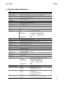
4. Technical Specifications
y General
Type
19" rack mounted, digital audio interface
Audio
Total 8-in / 8-out, 24bit, audio interface
System Clock Support
Internal (44.1, 48.0, 88.2, 96.0, 176.4, 192.0 kHz), Word Clock, Digital In, E.D.I
WORD Clock IN
FS / 256*FS, BNC Connector
Power
AC IN 100V ~ 240V, 50Hz ~ 60Hz, 30W
Weight
3.5kg
Dimensions
482(mm) x 180(mm) x 86(mm)
y Analog Inputs
Type
Balanced 1/4” TRS (Balanced XLR ) Input
Level
+4dBu Nominal (@-16.2dBFS) , +20.2dBu max
Gain Range
0.0dB (@Gain min, +20.2dBu max) ~ +29.0dB (@Gain max, -7.8dBu max)
Frequency Response
20Hz to 20kHz, +/- 0.1dB
THD + N
0.0003% A-weighted (@ -3dBFS)
Dynamic Range
116dB A-weighted
CMRR
75dB
Impedance
10K ohm (1/4” TRS), Low impedance : 3K ohm (XLR)
A/D Converter
Type
Dynamic Range
S/(N+D) Ratio
Frequency Response
Interchannel Isolation
Gain Mismatch
24bit, 192KHz, 128X Oversampling
123dB (@ -60dBFS with A-Weighted)
110dB (@ -1dBFS, measurement method)
6.5 ~ 21.768KHz, +/- 0.001dB (@ fs=48KHz)
6.5 ~ 43.536KHz, +/- 0.003dB (@ fs=96KHz)
6.5 ~ 87.072KHz, +/- 0.007dB (@ fs=192KHz)
123dB
0.1dB
y MIC Pre-amp
Type
Level
Gain Range
Equivalent Input Noise
THD + N
Dynamic Range
CMRR
Impedance
Balanced XLR (+48V Phantom Power support)
500 mV max (-3.8dBu)
+25.0dB (@Gain min, -3.8dBu) ~ +73dB (@Gain max, -51.8dBu)
- 135.5dBu (@ 0 ohm, 20Hz ~ 20kHz)
0.00065% A-weighted (@ gain+35dB)
103dB A-weighted (@ gain +35dB)
90dB
1.5K ohm
y Analog outputs
Type
Frequency Response
+4dBu Balanced XLR output
-10dBv Balanced/Unbalanced 1/4” TRS output
+4dBu Nominal (@-16dBFS) , +20.0dBu max
-10dBu Nominal (@-16dBFS) , +8.2dBu max
20Hz to 20kHz, +/- 0.05dB
Analog Filter
3-pole low-pass filter
Level
THD + N
0.0001% A-weighted (@ -3dBFS)
Dynamic Range
118dB A-weighted
Impedance
110 ohm (1/4” TRS), 110 ohm (XLR)
D/A Converter
Type
Dynamic Range
S/(N+D) Ratio
Frequency Response
Interchannel Isolation
Gain Mismatch
24bit, 192KHz, 128X Oversampling, 8 times digital filter
120dB (@ -60dBFS with A-Weighted)
100dB (@ -1dBFS, measurement method)
0 ~ 21.7KHz, +/- 0.002dB (@ fs=48KHz)
0 ~ 43.5KHz, +/- 0.002dB (@ fs=96KHz)
0 ~ 87.0KHz, +/- 0.002dB (@ fs=192KHz)
120dB
0.15dB
y Digital Audio
AES/EBU, Coaxial (S/PDIF)
ADAT
E.D.I
Connector
Impedance
Format
Sample rate
Connector
Format
Sample rate
Connector
Format
Sample rate
XLR (AES/EBU), RCA (S/PDIF) I/O
XLR : 110ohm, RCA : 75ohm
IEC-60958 Professional / Consumer
44.1, 48.0, 88.2, 96.0, 176.4, 192.0 kHz
TOS-Link (Optical) I/O
ADAT® protocol
44.1, 48.0kHz (8channel)
88.2, 96.0kHz (4channel - SMUX )
176.4, 192.0kHz (2channel - SMUX )
IEEE1394 compatible
E.D.I protocol
44.1, 48.0, 88.2, 96.0, 176.4, 192.0 kHz (8 channel)
15