1
(63$f2/
)5$1d$,6
(1*/,6+
$96XUURXQG5HFHLYHU
SR5005
(63$f2/
IMPORTANT SAFETY
INSTRUCTIONS
n SAFETY PRECAUTIONS
CAUTION
RISK OF ELECTRIC SHOCK
DO NOT OPEN
CAUTION:
TO REDUCE THE RISK OF ELECTRIC SHOCK, DO NOT REMOVE
COVER (OR BACK). NO USER-SERVICEABLE PARTS INSIDE.
REFER SERVICING TO QUALIFIED SERVICE PERSONNEL.
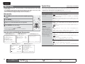
The lightning flash with arrowhead symbol, within an equilateral
triangle, is intended to alert the user to the presence of
uninsulated “dangerous voltage” within the product’s enclosure
that may be of sufficient magnitude to constitute a risk of
electric shock to persons.
The exclamation point within an equilateral triangle is intended
to alert the user to the presence of important operating
and maintenance (servicing) instructions in the literature
accompanying the appliance.
WARNING:
1.
2.
3.
4.
5.
6.
7.
8.
9.
10.
11.
12.
TO REDUCE THE RISK OF FIRE OR ELECTRIC SHOCK, DO NOT
EXPOSE THIS APPLIANCE TO RAIN OR MOISTURE.
13.
Read these instructions.
Keep these instructions.
Heed all warnings.
Follow all instructions.
Do not use this apparatus near water.
Clean only with dry cloth.
Do not block any ventilation openings.
Install in accordance with the manufacturer’s instructions.
Do not install near any heat sources such as radiators, heat registers,
stoves, or other apparatus (including amplifiers) that produce heat.
Do not defeat the safety purpose of the polarized or grounding-type plug. A
polarized plug has two blades with one wider than the other. A grounding
type plug has two blades and a third grounding prong. The wide blade or the
third prong are provided for your safety. If the provided plug does not fit into
your outlet, consult an electrician for replacement of the obsolete outlet.
Protect the power cord from being walked on or pinched particularly at
plugs, convenience receptacles, and the point where they exit from the
apparatus.
Only use attachments/accessories specified by the manufacturer.
Use only with the cart, stand, tripod, bracket, or table
specified by the manufacturer, or sold with the apparatus.
When a cart is used, use caution when moving the cart/
apparatus combination to avoid injury from tip-over.
Unplug this apparatus during lightning storms or when
unused for long periods of time.
14. Refer all servicing to qualified service personnel.
Servicing is required when the apparatus has been damaged in any way,
such as power-supply cord or plug is damaged, liquid has been spilled or
objects have fallen into the apparatus, the apparatus has been exposed to
rain or moisture, does not operate normally, or has been dropped.
15. Batteries shall not be exposed to excessive heat such as sunshine, fire or
the like.
CAUTION:
)5$1d$,6
(1*/,6+
FCC INFORMATION (For US customers)
1. PRODUCT
This product complies with Part 15 of the FCC Rules. Operation is subject
to the following two conditions: (1) this product may not cause harmful
interference, and (2) this product must accept any interference received,
including interference that may cause undesired operation.
2. IMPORTANT NOTICE: DO NOT MODIFY THIS PRODUCT
This product, when installed as indicated in the instructions contained
in this manual, meets FCC requirements. Modification not expressly
approved by Marantz may void your authority, granted by the FCC, to use
the product.
3. NOTE
This product has been tested and found to comply with the limits for
a Class B digital device, pursuant to Part 15 of the FCC Rules. These
limits are designed to provide reasonable protection against harmful
interference in a residential installation.
This product generates, uses and can radiate radio frequency energy and,
if not installed and used in accordance with the instructions, may cause
harmful interference to radio communications. However, there is no
guarantee that interference will not occur in a particular installation. If this
product does cause harmful interference to radio or television reception,
which can be determined by turning the product OFF and ON, the user
is encouraged to try to correct the interference by one or more of the
following measures:
• Reorient or relocate the receiving antenna.
• Increase the separation between the equipment and receiver.
• Connect the product into an outlet on a circuit different from that to
which the receiver is connected.
• Consult the local retailer authorized to distribute this type of product or
an experienced radio/TV technician for help.
For Canadian customers:
This Class B digital apparatus complies with Canadian ICES-003.
Cet appareil numérique de la classe B est conforme à la norme NMB-003 du
Canada.
To completely disconnect this product from the mains, disconnect the plug
from the wall socket outlet.
The mains plug is used to completely interrupt the power supply to the unit
and must be within easy access by the user.
PRECAUTION:
Pour déconnecter complètement ce produit du courant secteur, débranchez
la prise de la prise murale.
La prise secteur est utilisée pour couper complètement l’alimentation de
l’appareil et l’utilisateur doit pouvoir y accéder facilement.
PRECAUCIÓN:
Para desconectar completamente este producto de la alimentación eléctrica,
desconecte el enchufe del enchufe de la pared.
El enchufe de la alimentación eléctrica se utiliza para interrumpir por completo
el suministro de alimentación eléctrica a la unidad y debe de encontrarse en
un lugar al que el usuario tenga fácil acceso.
I
(1*/,6+
)5$1d$,6
(63$f2/
n NOTES ON USE / OBSERVATIONS RELATIVES A L’UTILISATION / NOTAS SOBRE EL USO
WARNINGS
AVERTISSEMENTS
ADVERTENCIAS
• Avoid high temperatures.
Allow for sufficient heat dispersion when
installed in a rack.
• Handle the power cord carefully.
Hold the plug when unplugging the cord.
• Keep the unit free from moisture, water, and
dust.
• Unplug the power cord when not using the unit
for long periods of time.
• Do not obstruct the ventilation holes.
• Do not let foreign objects into the unit.
• Do not let insecticides, benzene, and thinner
come in contact with the unit.
• Never disassemble or modify the unit in any way.
• Ventilation should not be impeded by covering
the ventilation openings with items, such as
newspapers, tablecloths or curtains.
• Naked flame sources such as lighted candles
should not be placed on the unit.
• Observe and follow local regulations regarding
battery disposal.
• Do not expose the unit to dripping or splashing
fluids.
• Do not place objects filled with liquids, such as
vases, on the unit.
• Do not handle the mains cord with wet hands.
• When the switch is in the OFF position, the
equipment is not completely switched off from
MAINS.
• The equipment shall be installed near the
power supply so that the power supply is easily
accessible.
• Eviter des températures élevées.
Tenir compte d’une dispersion de chaleur
suffisante lors de l’installation sur une étagère.
• Manipuler le cordon d’alimentation avec
précaution.
Tenir la prise lors du débranchement du cordon.
• Protéger l’appareil contre l’humidité, l’eau et la
poussière.
• Débrancher le cordon d’alimentation lorsque
l’appareil n’est pas utilisé pendant de longues
périodes.
• Ne pas obstruer les trous d’aération.
• Ne pas laisser des objets étrangers dans
l’appareil.
• Ne pas mettre en contact des insecticides, du
benzène et un diluant avec l’appareil.
• Ne jamais démonter ou modifier l’appareil d’une
manière ou d’une autre.
• Ne pas recouvrir les orifices de ventilation avec
des objets tels que des journaux, nappes ou
rideaux. Cela entraverait la ventilation.
• Ne jamais placer de flamme nue sur l’appareil,
notamment des bougies allumées.
• Veillez à respecter les lois en vigueur lorsque
vous jetez les piles usagées.
• L’appareil ne doit pas être exposé à l’eau ou à
l’humidité.
• Ne pas poser d’objet contenant du liquide, par
exemple un vase, sur l’appareil.
• Ne pas manipuler le cordon d’alimentation avec
les mains mouillées.
• Lorsque l’interrupteur est sur la position OFF,
l’appareil n’est pas complètement déconnecté du
SECTEUR (MAINS).
• L’appareil sera installé près de la source
d’alimentation, de sorte que cette dernière soit
facilement accessible.
• Evite altas temperaturas.
Permite la suficiente dispersión del calor cuando
está instalado en la consola.
• Maneje el cordón de energía con cuidado.
Sostenga el enchufe cuando desconecte el
cordón de energía.
• Mantenga el equipo libre de humedad, agua y
polvo.
• Desconecte el cordón de energía cuando no
utilice el equipo por mucho tiempo.
• No obstruya los orificios de ventilación.
• No deje objetos extraños dentro del equipo.
• No permita el contacto de insecticidas, gasolina
y diluyentes con el equipo.
• Nunca desarme o modifique el equipo de
ninguna manera.
• La ventilación no debe quedar obstruida por
haberse cubierto las aperturas con objetos como
periódicos, manteles o cortinas.
• No deberán colocarse sobre el aparato fuentes
inflamables sin protección, como velas
encendidas.
• A la hora de deshacerse de las pilas, respete la
normativa para el cuidado del medio ambiente.
• No exponer el aparato al goteo o salpicaduras
cuando se utilice.
• No colocar sobre el aparato objetos llenos de
líquido, como jarros.
• No maneje el cable de alimentación con las
manos mojadas.
• Cuando el interruptor está en la posición OFF, el
equipo no está completamente desconectado de
la alimentación MAINS.
• El equipo se instalará cerca de la fuente de
alimentación de manera que resulte fácil acceder
a ella.
II
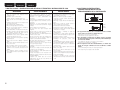
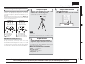
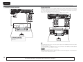
n CAUTIONS ON INSTALLATION
PRÉCAUTIONS D’INSTALLATION
EMPLAZAMIENTO DE LA INSTALACIÓN
z
z
z
z
Wall
Paroi
Pared
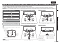
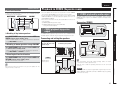
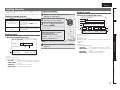
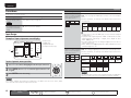
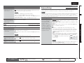
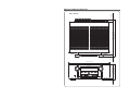
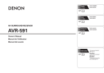
zFor proper heat dispersal, do not install this unit in a confined
space, such as a bookcase or similar enclosure.
• More than 0.3 m (12 in.) is recommended.
• Do not place any other equipment on this unit.
zPour permettre la dissipation de chaleur requise, n’installez
pas cette unité dans un espace confiné tel qu’une bibliothèque
ou un endroit similaire.
• Une distance de plus de 0,3 m (12 po) est recommandée.
• Ne placez aucun matériel sur cet appareil.
zPara la dispersión del calor adecuadamente, no instale este
equipo en un lugar confinado tal como una librería o unidad
similar.
• Se recomienda dejar más de 0,3 m (12 pulg.) alrededor.
• No coloque ningún otro equipo sobre la unidad.
69(16.$
1('(5/$1'6
(63$f2/
,7$/,$12
)5$1d$,6
'(876&+
(1*/,6+
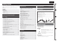
Thank you for purchasing this Marantz product. To ensure proper
operation, please read this user guide carefully before using the
product.
After reading them, be sure to keep them for future reference.
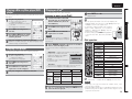
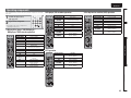
Contents
Simple version (Simple setup guide) ··························3
Basic version ··········································································12
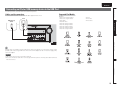
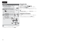
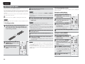
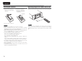
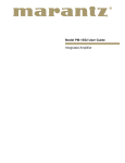
Accessories
Check that the following parts are supplied with the product.
q User guide ............................................................................... 1
w Warranty card (for USA) .......................................................... 1
e Warranty card (for CANADA) ................................................... 1
r Power cord .............................................................................. 1
t Remote control unit (RC010SR) .............................................. 1
y R03/AAA batteries ................................................................... 2
u Setup microphone (ACM1H) ................................................... 1
i AM loop antenna ..................................................................... 1
o FM indoor antenna .................................................................. 1
r
u
i
o
About this manual
n Operation buttons
The operations described in this manual are based mainly on
remote control operation.
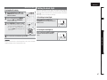
n Symbols
v
Information ·············································································68
This symbol indicates a reference page on which
related information is described.
This symbol indicates a supplementary information
and tips for operations.
NOTE
This symbol indicates points to remember operations
or function limitations.
n Illustrations
Note that the illustrations in these instructions are for explanation
purposes and may differ from the actual unit.
1
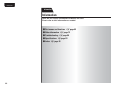
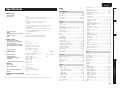
Information
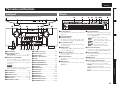
Part names and functions···························································69
Front panel ··················································································69
Display ························································································69
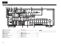
Rear panel ···················································································70
Remote control unit ····································································71
Other information ·······································································73
Trademark information································································73
Surround ·····················································································74
Explanation of terms ···································································78
Troubleshooting ··········································································80
Resetting the microprocessor ····················································82
Specifications ··············································································83
t
Advanced version
Connections ·················································································13
Important information ·································································13
Connecting an HDMI-compatible device ····································14
Connecting a TV··········································································16
Connecting a Blu-ray Disc player / DVD player ···························16
Connecting a set-top box (Satellite tuner/cable TV) ····················17
Connecting a video cassette recorder ········································17
Connecting a digital camcorder ··················································18
Connecting a CD player ······························································18
Connecting a wireless receiver (RX101) ·····································18
Connecting an iPod or USB memory device to the USB Port ····19
Connecting an antenna ·······························································20
Connect a device that has a multichannel output terminal ·········21
Connecting a external power amplifier ·······································21
Playback (Basic operation) ·························································22
Important information ·································································22
Playing a Blu-ray Disc player/DVD player ····································23
Playing a CD player ·····································································23
Playing an iPod® ·········································································23
Playing a USB memory device····················································24
Tuning in radio stations ·······························································25
Selecting a listening mode (Surround mode) ··························29
Multi-channel playback ·······························································29
Stereo playback ··········································································31
Direct playback ···········································································31
Dolby Virtual Speaker/Dolby Headphone playback ·····················31
List of preset codes ··································End of this manual
Basic version
Getting started ··············································································1
Accessories ··················································································1
About this manual ·········································································1
Features ························································································2
Cautions on handling ····································································2
Advanced version ·······························································32
Speaker installation/connection (Other than
7.1-channel system with surround back speakers)··················33
Install ··························································································33
Connect ······················································································34
Set up speakers ·········································································37
Connections (Advanced connection)·········································38
REMOTE CONTROL jacks ··························································38
RS-232C connector ·····································································38
DC OUT (TRIGGER OUT) jacks ···················································38
Playback (Advanced operation) ·················································39
Convenient functions ··································································39
Playback in ZONE2 (Separate room) ········································41
q ZONE2 playback by speaker output ·······································41
w ZONE2 playback by audio output ···········································41
Playback ······················································································42
How to make detailed settings ··················································43
Menu map ··················································································43
Examples of on-screen display and front display ························44
Inputting characters ···································································45
Input Setup ·················································································46
Audio Adjust ···············································································52
Manual Setup··············································································56
Information ·················································································61
Other settings ··············································································62
Remote control settings ·····························································62
Switching the on-screen display output mode ···························62
Operating the connected devices by remote control unit ······63
Operating AV equipment ····························································63
Registering preset codes ····························································63
Operating components ·······························································65
Operating learn mode ·································································66
Setting the back light ··································································67
Simple version
Getting started
(1*/,6+
'(876&+
)5$1d$,6
,7$/,$12
(63$f2/
1('(5/$1'6
69(16.$
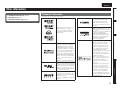
Features
Fully Discrete, identical quality and power for all
7 channels (100 W x 7ch, 8Ω)
The unit is equipped with a power amplifier that plays back highfidelity sound in surround mode with equal quality and power for all
channels, true to the original sound.
The power amplifier circuit adopts a discrete-circuit configuration
that achieves high-quality surround sound play back.
Supports HDMI 1.4a with 3D, ARC, Deep Color,
x.v.Color , Auto Lipsync and HDMI control function
This unit can output 3D video signals input from a Blu-ray Disc
player to a TV that supports a 3D system. This unit also supports
the ARC (Audio Return Channel) function, which plays back TV
sound with this unit via an HDMI cable used for connecting the
unit and a TVz.
zThe TV should support the ARC function.
4-HDMI inputs and 1-output
The unit is equipped with 4 HDMI input connectors for connecting
devices with HDMI connectors, such as a Blu-ray Disc player,
game machine, HD video camera, etc.
Cautions on handling
Auto setup function
The unit is provided with an “Auto setup function” which
automatically makes speaker settings best suited for the listening
environment. The sound from the speakers is picked up with the
supplied microphone. Reflecting sound and audio characteristics of
speakers are measured, and settings for an optimum sound field
are automatically made.
All sources are up-scaled to 1080p
The unit is provided with an HDMI video upscaling function that
converts an analog video signal input to the unit to a 1080p (HD
resolution) signal and supplies it to a TV via the HDMI connector.
This enables the unit and a TV connected with a single HDMI cable
and any video source to be reproduced precisely with HD level of
quality.
Direct Play for iPod® and iPhone® via USB
Music data from an iPod can be played back if you connect the
USB cable supplied with the iPod via the USB port of this unit, and
also an iPod can be controlled with the remote control unit for this
unit.
M-XPort (Marantz-eXtension Port)
High Definition Audio Support
The unit is equipped with a decoder which supports high-quality
digital audio format for Blu-ray Disc players such as Dolby TrueHD,
DTS-HD Master Audio, etc.
This unit is equipped with the M-Xport, a Marantz original innovation
that provides outstanding expandability. You can connect the
Wireless Receiver RX101 (sold separately) to this port.
Speaker terminal for front height channel
Dolby Pro Logic gz
The unit is provided with a Dolby Pro Logic gz decoder. When
you play back the sound in Dolby Pro Logic gz playback with front
height speakers connected to the unit, you can enjoy playback
sound with rich spacial expression.
The unit is equipped with dedicated front height channel speaker
terminals on the rear panel. You can enjoy 7.1-channel playback
using the front height channel and 7.1-channel playback using the
surround back channel, without having to reconnect the speakers.
Other features
Easy to use, On-Screen Display
Simple settings are enabled with the setting menus displayed on
the TV screen. When you control the sound volume, the volume
level is displayed on the screen, and when you switch the input
source, the name of the input source is displayed.
2
• Dolby Virtual Speaker (vpage 31)
• Dolby Headphone vpage 31)
• DTS Neural Surround (vpage 29)
• Before turning the power switch on
Check once again that all connections are correct and that there are
no problems with the connection cables.
• Power is supplied to some of the circuitry even when the unit is
set to the standby mode. When going on vacation or leaving home
for long periods of time, be sure to unplug the power cord from the
power outlet.
• About Condensation
If there is a major difference in temperature between the inside of
the unit and the surroundings, condensation (dew) may form on
the operating parts inside the unit, causing the unit not to operate
properly.
If this happens, let the unit sit for an hour or two with the power
turned off and wait until there is little difference in temperature
before using the unit.
• Cautions on using mobile phones
Using a mobile phone near this unit may result in noise. If that
occurs, move the mobile phone away from this unit when it is in use.
• Moving the unit
Turn off the power and unplug the power cord from the power
outlet. Next, disconnect the connection cables to other system units
before moving the unit.
• About Care
• Wipe the cabinet and control panel clean with a soft cloth.
• Follow the instructions when using a chemical cleaner.
• Benzene, paint thinner or other organic solvents as well as
insecticide may cause material changes and discoloration if brought
into contact with the unit, and should therefore not be used.
69(16.$
(63$f2/
,7$/,$12
)5$1d$,6
'(876&+
(1*/,6+
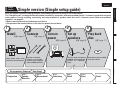
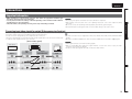
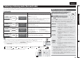
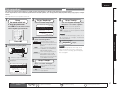
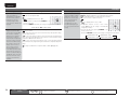
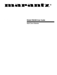
Simple version (Simple setup guide)
1
2
Install
3
Connect
(vpage 4)
(vpage 4)
4
Turn on
power
5
Set up
speakers
(vpage 6)
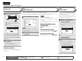
Basic version
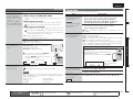
Here, we explain the entire setup procedure, from unboxing the unit to using it in a home theater.
The “Simple version” section provides the speaker installation, connection, and setup methods for the 7.1-channel system with surround
back speakers. For the installing, connecting, and setup methods of speakers other than the 7.1-channel system (with surround back
speakers), see page 33.
n Before connecting the unit, turn off the power to all devices.
n For operation of the connected devices, refer to the user manuals for each device.
Simple version
Simple
version
1('(5/$1'6
Play back
disc
(vpage 6)
(vpage 11)
Advanced version
Enjoy better audio, using
the correct install method.
Connect 7.1-channel
speakers, a TV and Bluray Disc player equipped
with an HDMI connector.
Use the setup microphone
(ACM1H) included with the
product, for automatic
setup.
Enjoy Blu-ray Disc and DVD
in surround sound.
Information
Set up speakers (Audyssey® Auto Setup)
Preparation
Step 1
Step 2
Step 3
Step 4
Step 5
Speaker
Detection
Measurement
Calculating
Check
Store
Finish
3
(1*/,6+
'(876&+
)5$1d$,6
,7$/,$12
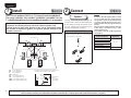
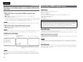
1 Install
(63$f2/
1
2
3
4
5
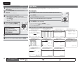
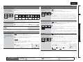
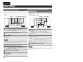
This unit can perform 2.0/2.1 to 7.1-channel surround playback.
This page provides the speaker installation procedure for the
7.1-channel playback using surround back speakers as an example.
The default setting is 7.1-channel. You can also perform 5.1-channel playback.
To perform 5.1-channel playback, connect 5.1-channel speakers only.
Use the Audyssey Auto Setup function of this unit to automatically detect
the number of connected speakers and perform optimal settings for the
speakers to be used.
1('(5/$1'6
69(16.$
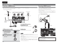
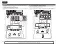
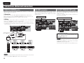
2 Connect
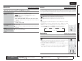
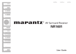
Speakers
Carefully check the left (L) and right (R)
channels and + (red) and – (black) polarities
on the speakers being connected to the
this unit, and be sure to interconnect the
channels and polarities correctly.
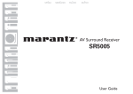
Connecting the speaker cables
Peel off about 0.03 ft/10 mm of sheathing from
the tip of the speaker cable, then either twist the
core wire tightly or terminate it.
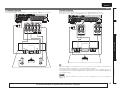
FL
C
22 – 30˚
90 – 110˚
Speaker terminals
SR
Listening
position
SBL
FL
FR
C
SW
SL
SR
SBL
SBR
Front speaker (L)
Front speaker (R)
Center speaker
Subwoofer
Surround speaker (L)
Surround speaker (R)
Surround back speaker (L)
Surround back speaker (R)
SBR
• Install the surround speakers in a position 2 to
3 ft (60 to 90 cm) higher than ear level.
Front
speaker
Surround
speaker
2 – 3 ft /
60 – 90 cm
Surround back
speaker
• Point slightly
downwards
GViewed from the sideH
4
3
4
5
NOTE
135 – 150˚
SL
2
• Connect so that the speaker cable core wires
do not protrude from the speaker terminal.
The protection circuit may be activated if the
core wires touch the rear panel or if the + and –
sides touch each other (vpage 79 “Protection
Circuit”).
• Never touch the speaker terminals while the
power supply is connected. Doing so could
result in electric shock.
• Use speakers with the speaker impedances
shown below.
FRONT A
CENTER
SURROUND
SURR. BACK/AMP ASSIGN
FRONT B/HEIGHT
FRONT A + FRONT B
FR
SW
1
The “Simple version” section provides the speaker installation, connection, and setup methods for the 7.1-channel system with surround back speakers.
For the installing, connecting, and setup methods of speakers other than the 7.1-channel system (with surround back speakers), see page 33.
Speaker
impedance
6−8Ω
8Ω
69(16.$
1('(5/$1'6
(63$f2/
,7$/,$12
)5$1d$,6
'(876&+
(1*/,6+
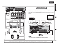
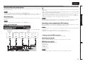
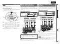
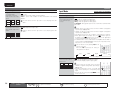
Blu-ray Disc player and TV
TV
Basic version
Use only an HDMI (High-Definition Multimedia Interface) cable that bears the HDMI
logo (a certified HDMI product). Using a cable without the HDMI logo (an uncertified
HDMI product) may result in abnormal playback.
When outputting Deep Color or 1080p, etc., we recommend you use a “High Speed
HDMI cable” or a “High Speed HDMI cable with Ethernet” for enhanced high-quality
playback.
Simple version
Connect
Blu-ray Disc player
Audio cable
(sold separately)
FL
SW
)%.*
*/
HDMI cable
(sold separately)
FR
Advanced version
)%.*
065
HDMI cable
(sold separately)
C
Subwoofer
with built-in
amplifier
Speaker cables
(sold separately)
SL
SR
SBL
SBR
Power cord
(supplied)
Information
To household power outlet
(AC 120 V, 60 Hz)
NOTE
• Do not plug in the power cord until all connections have been completed.
• Do not bundle power cords together with connection cables. Doing so can result in humming or noise.
The “Simple version” section provides the speaker installation, connection, and setup methods for the 7.1-channel system with surround back speakers.
For the installing, connecting, and setup methods of speakers other than the 7.1-channel system (with surround back speakers), see page 33.
5
(1*/,6+
'(876&+
)5$1d$,6
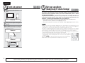
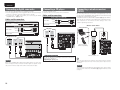
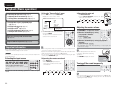
3 Turn on power
1
7XUQRQWKH79DQGVXEZRRIHU
SRZHU
Power on
2 &KDQJHWKH79LQSXWWRWKHLQSXWRI
WKLVXQLW
3 3UHVVONWRWXUQRQSRZHUWRWKHXQLW
The power indicator switches off, and power
is supplied to the unit.
Power on
,7$/,$12
(63$f2/
1
2
3
4
5
1('(5/$1'6
69(16.$
4 Set up speakers
(Audyssey® Auto Setup)
2
3
4
5
The acoustic characteristics of the connected speakers and listening room are
measured and the optimum settings are made automatically. This is called
“Audyssey Auto Setup”.
To perform measurement, place the setup microphone in multiple locations all
around the listening area. For best results, we recommend you measure in six
positions, as shown in the illustration (up to six positions).
• When performing Audyssey Auto Setup, MultEQ®/Dynamic EQ®/Dynamic
Volume® functions become active (vpage 53, 54).
• To set up the speakers manually, use “Speaker Setup” (vpage 56) on the menu.
NOTE
• Make the room as quiet as possible. Background noise can disrupt the room measurements. Close
windows, silence cell phones, televisions, radios, air conditioners, fluorescent lights, home appliances,
light dimmers, or other devices as measurements may be affected by these sounds.
• Cell phones should be placed away from all audio electronics during the measurement process as Radio
Frequency Interference (RFI) may cause measurement disruptions (even if the cell phone is not in use).
• Do not unplug the setup microphone from the main unit until Audyssey Auto Setup is completed.
• Do not stand between the speakers and setup microphone or allow obstacles in the path while the
measurements are being made. This will cause inaccurate readings.
• Loud test sounds may be played during Audyssey Auto setup. This is part of
normal operation. If there is background noise in room, these test signals will
increase in volume.
• Operating VOLUME + – during the measurements will cancel the measurements.
• Measurement cannot be performed when headphones are connected.
Power on
6
1
The “Simple version” section provides the speaker installation, connection, and setup methods for the 7.1-channel system with surround back speakers.
For the installing, connecting, and setup methods of speakers other than the 7.1-channel system (with surround back speakers), see page 33.
69(16.$
1('(5/$1'6
(63$f2/
,7$/,$12
)5$1d$,6
'(876&+
(1*/,6+
Set up speakers (Audyssey® Auto Setup)
GExample qH
GExample wH
FL SW C
FL SW C
FR
( : Measuring positions)
Sound receptor
SBL
SL
SR
SBL
SBR
Set up the remote control unit
n Set up the operation mode
3UHVVAMPWRVHWWKHUHPRWHFRQWUROXQLWWRDPSOL¿HU
RSHUDWLRQPRGH
Setup
microphone
FR
*M
SL
SBR
FL Front speaker (L)
FR Front speaker (R)
C Center speaker
SW Subwoofer
When placing the setup microphone, adjust the height of the
sound receptor to the level of the listener’s ear.
Press AMP
( : Measuring positions)
SR
SBL
0RXQW WKH VHWXS PLFURSKRQH RQ D WULSRG RU VWDQG
DQGSODFHLWLQWKHPDLQOLVWHQLQJSRVLWLRQ
3
Advanced version
*M
SL
Set up the microphone
Basic version
• Measurements are performed by placing the setup microphone
successively at multiple positions throughout the entire listening
area, as shown in GExample qH. For best results, we recommend
you measure in six positions, as shown in the illustration (up to six
positions).
• Even if the listening environment is small as shown in GExample wH,
measuring at multiple points throughout the listening environment
results in more effective correction.
1
Simple version
About setup microphone placement
SR
SBR
Surround speaker (L)
Surround speaker (R)
Surround back speaker (L)
Surround back speaker (R)
About the main listening position (*M)
The main listening position is the position where listeners would
normally sit or where one would normally sit alone within the listening
environment. Before starting Audyssey Auto Setup, place the setup
microphone in the main listening position. Audyssey MultEQ® uses
the measurements from this position to calculate speaker distance,
level, polarity, and the optimum crossover value for the subwoofer.
NOTE
• Do not hold the setup microphone in your hand during
measurements.
• Avoid placing the setup microphone close to a seat back or wall as
sound reflections may give inaccurate results.
2
Set up the subwoofer
,IXVLQJDVXEZRRIHUFDSDEOHRIWKHIROORZLQJ
DGMXVWPHQWVVHWXSWKHVXEZRRIHUDVVKRZQEHORZ
n When using a subwoofer with a direct mode
Set the direct mode to “On” and disable the volume adjustment
and crossover frequency setting.
n When using a subwoofer without a direct mode
The “Simple version” section provides the speaker installation, connection, and setup methods for the 7.1-channel system with surround back speakers.
For the installing, connecting, and setup methods of speakers other than the 7.1-channel system (with surround back speakers), see page 33.
Information
Make the following settings:
• Volume : “12 o’clock position”
• Crossover frequency :
“Maximum/Highest Frequency”
• Low pass filter : “Off”
• Standby mode : “Off”
7
(1*/,6+
'(876&+
)5$1d$,6
,7$/,$12
(63$f2/
1('(5/$1'6
69(16.$
Set up speakers (Audyssey® Auto Setup)
Preparation
4
&RQQHFWWKHVHWXSPLFURSKRQHWRWKH
6(7830,&MDFNRIWKLVXQLW
Step 1
Step 2
Speaker Detection
Measurement
• In step 1, you will perform measurements at the main listening position.
• This step automatically checks the speaker configuration and speaker size, and calculates the channel
level, distance, and crossover frequency. It also corrects distortion in the listening area.
6
When the setup microphone is
connected, the following screen is
displayed.
3-1.Audyssey Auto Setup
MultEQ
Please place microphone
at ear height at
main listening position.
F.Height : Measure
Front Sp. : A
Amp Assign: Normal
Start
Cancel
[ENT]:Select [RTN]:Back
The setting method for 7.1-channel playback using
the surround back speakers is described here.
For the method of setting up speakers other than
the 7.1-channel system, select “Amp Assign”
and perform steps 3 and 4 of “Set up speakers”
(vpage 37).
5
7KHGHWHFWHGVSHDNHUVDUHGLVSOD\HG
Step1:Speaker Detection
MultEQ
Front Sp.
:Yes
F.Height Sp.
:No
Center Sp.
:Yes
Surround Sp.
:Yes
S.Back Sp.
:Yes 2ch
Subwoofer
:Yes
Next
Retry
[ENT]:Next
NOTE
If a connected speaker is not displayed, the
speaker may not be connected correctly. Check
the speaker connection.
8VH ui WR VHOHFW ³1H[W´ DQG WKHQ
7 SUHVV
ENTER
NOTE
If “Caution” is displayed:
Go to “Error messages” (vpage 10), check
any related items, and perform the necessary
procedures.
If the problem is resolved, return and restart
“Audyssey Auto Setup”.
8 0RYHWKHVHWXSPLFURSKRQHWR
SRVLWLRQXVHuiWRVHOHFW³1H[W´
DQGWKHQSUHVVENTER
The measurement of the second position
starts. Measurements can be made in up to
six positions.
When performing Audyssey Auto
Setup over again
Press ui to select “Retry”, and then press
ENTER.
When measuring has stopped
Press ui to select “Cancel”, then press ENTER.
Press o p to select “Yes”, then press ENTER.
Step2:Measurement
MultEQ
Please place microphone
at ear height at
2nd listening position.
Next
Calculate
Cancel
[ENT]:Next
Setting up the speakers again
Repeat the operation from step 4 of Preparation
• In step 2, you will perform measurements at
multiple positions (two to six positions) other than
the main listening position.
• You can achieve a more effective correction of
distortion within the listening area by performing
measurements at multiple positions.
.
If you want to omit measurements from the next
position onward, select “Calculate”.
(Go to Step 3 Calculating
)
9 5HSHDWVWHSPHDVXULQJSRVLWLRQV
WR
8VH ui WR VHOHFW ³6WDUW´ DQG WKHQ
SUHVVENTER
When measurement of position 6 is
completed, a “All the measurements were
finished.” message is displayed.
When measuring begins, a test tone is
output from each speaker.
Step2:Measurement
• Measurement requires several minutes.
MultEQ
All the measurements
were finished.
If “Cancel” is selected
Calculate
Retry
Cancel
“Cancel Auto Setup?” is displayed on the TV
screen. If “Yes” is selected, “Audyssey Auto
Setup” closes.
8
Remote control operation
buttons
[ENT]:Calculate
Move the cursor
(Up/Down/Left/Right)
Confirm the setting
Return to previous menu
69(16.$
1('(5/$1'6
(63$f2/
,7$/,$12
)5$1d$,6
'(876&+
(1*/,6+
Set up speakers (Audyssey® Auto Setup)
Step 4
Step 5
Calculating
Check
Store
Simple version
Step 3
Finish
8QSOXJ WKH VHWXS PLFURSKRQH IURP
8VH uiWRVHOHFWWKHLWHP\RXZDQW
8VH ui WR VHOHFW ³6WRUH´ DQG WKHQ
VFUHHQXVHui
10 2QWKH
11
13
14
WKHXQLW¶V6(7830,&MDFN
WRFKHFNDQGWKHQSUHVV
SUHVV
ENTER
ENTER
WRVHOHFW³&DOFXODWH´DQGWKHQSUHVV
ENTER
15 6HW'\QDPLF9ROXPH®
Step 2
MultEQ
Please check the results
of the measured item.
Measuring results are analyzed, and the
frequency response of each speaker in the
listening room is determined.
MultEQ
Calculating
Please wait...
MultEQ
Please select “Store”
to store measurement
values.
• Subwoofers may measure a greater reported
distance than the actual distance due to added
electrical delay common in subwoofers.
• If you want to check another item, press
RETURN.
12
Store
Cancel
Turn on Dynamic Volume?
Yes : No
[
MultEQ
Storing
Please wait...
[----------]
[ENT]:Exit
• Saving the results requires about 10 seconds.
• If you do not want to save the measurement
results, use ui to select “Cancel”, then select
“Yes” using o p. All the measured Audyssey
Auto Setup data will be erased.
n When turning Dynamic Volume on
• Use o to select “Yes”, and then press ENTER.
The unit automatically enters “Evening” mode.
n When turning Dynamic Volume off
• Use p to select “No”, and then press ENTER.
NOTE
After performing Audyssey Auto Setup, do not
change the speaker connections or subwoofer
volume. In event of a change, perform Audyssey
Auto Setup again.
NOTE
During saving of measurement results, be sure
not to turn off the power.
Information
Move the cursor
(Up/Down/Left/Right)
]:Select
• For details of Dynamic Volume settings, see
page 54.
Step5:Store
NOTE
Remote control operation
buttons
MultEQ
Storing complete.
Auto Setup is now
finished.
[ENT]:Store
8VH ui WR VHOHFW ³1H[W´ DQG WKHQ
SUHVVENTER
• If the result differs from the actual connection
status, or if “Caution!” is displayed, see “Error
messages” (vpage 10). Then carry out Audyssey
Auto Setup again.
• If the result still differs from the actual connection
status after remeasurement or the error message
still appears, it is possible that the speakers
are not connected properly. Turn this unit off,
check the speaker connections and repeat the
measurement process from the beginning.
• If you change speaker positions or orientation,
perform Audyssey Auto Setup again to find the
optimal equalizer settings.
Finish
Advanced version
• Analysis takes several minutes to complete. The
time required for this analysis depends on the
number of speakers connected.
The more connected speakers there are, the
longer it takes to perform analysis.
Step5:Store
Speaker Config.Check
Distance Check
Channel Level Check
Crossover Freq.Check
Next
[ENT]:Select
Step3:Calculating
[----------]
Save the measurement results.
Basic version
Step4:Check
Confirm the setting
Return to previous menu
9
(1*/,6+
'(876&+
)5$1d$,6
,7$/,$12
(63$f2/
1('(5/$1'6
69(16.$
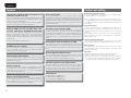
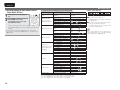
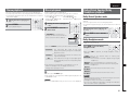
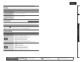
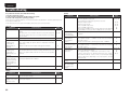
Error messages
Parameter Check
An error message is displayed if Audyssey® Auto Setup could not be completed due to speaker placement, the measurement environment, etc.
If this happens, check the relevant items, be sure to take the necessary measures, then perform Audyssey Auto Setup over again.
This function enables you to check the measurement results and
equalizer characteristics after Audyssey Auto Setup.
NOTE
Be sure to turn off the power before checking speaker connections.
Examples
Error details
Caution
MultEQ
FMicrophone:None
or
Speaker
:None
Measures
• The connected setup microphone is broken, or a • Connect the included setup microphone to the
device other than the supplied setup microphone SETUP MIC jack of this unit.
is connected.
• Not all speakers could be detected.
• The front L speaker was not properly detected. • Check the speaker connections.
8VH ui WR VHOHFW ³3DUDPHWHU &KHFN´ DQG WKHQ
1 SUHVV
ENTER
8VH uiWRVHOHFWWKHLWHP\RXZDQWWRFKHFNWKHQ
2 SUHVV
ENTER
3-2.Parameter Check
Speaker Config.Check
Distance Chenck
Channel Level Check
Crossover Freq.Check
EQ Check
Retry
Cancel
[ENT]:Retry
Restore
Caution
MultEQ
noise is
too high or
Level is too low.
FAmbient
Retry
Cancel
• There is too much noise in the room for accurate • Either turn off any device generating noise or
measurements to be made.
move it away.
• Perform again when the surroundings are quieter.
• Speaker or subwoofer sound is too low for • Check the speaker installation and the direction
accurate measurements to be made.
in which the speakers are facing.
• Adjust the subwoofer’s volume.
[ENT]:Retry
• The displayed speaker could not be detected.
Caution
• Check the connections of the displayed speaker.
[ENT]:Select [RTN]:Back
Speaker Config. Check
Distance Check
Check the speaker configuration.
Check the distance.
Channel Level Check
Check the channel level.
Crossover Freq. Check
Check the crossover frequency.
EQ Check
Check the equalizer.
MultEQ
• If “EQ Check” is selected, press ui to select equalizing curve
(“Audyssey” or “Audyssey Flat”) to be checked.
Use o p to switch the display between the different speakers.
Front
R :None
[
Retry
Cancel
Skip
]:Up/Down [
Caution
MultEQ
Front
L :Phase
[
10
Retry
Cancel
Skip
]:Up/Down [
3 3UHVVRETURN
]:CH
The confirmation screen reappears. Repeat step 2.
• The displayed is connected with the polarities • Check the polarities of the displayed speaker.
reversed.
• For some speakers, this error message may
be displayed even if the speaker is properly
connected. If you are sure the connection is
correct, press ui to select “Skip”, then press
ENTER.
Retrieving Audyssey Auto Setup settings
If you set “Restore” to “Yes”, you can return to Audyssey Auto Setup
measurement result (value calculated at the start by MultEQ®) even
when you have changed each setting manually.
]:CH
Remote control operation
buttons
Move the cursor
(Up/Down/Left/Right)
Confirm the setting
Return to previous menu
69(16.$
1('(5/$1'6
(63$f2/
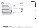
1
3UHVVBDWZRWLPHVLQDURZ
WRVZLWFKDQLQSXWVRXUFHIRUD
SOD\HUXVHGIRUSOD\EDFN
Make the necessary settings on the
player (language setting, subtitles
setting, etc.) beforehand.
2
3
4
'(876&+
(1*/,6+
5
When power is switched to standby
Press STANDBY.
GPower indicator status in standby modeH
• Normal standby : Red
• When “HDMI Control” is set to “ON” : Orange
Basic version
2 3OD\WKHFRPSRQHQWFRQQHFWHGWR
WKLVXQLW
1
)5$1d$,6
Simple version
5 Play back disc
,7$/,$12
You can also switch the power to standby by
pressing ON/STANDBY on the main unit.
3 $GMXVWWKHVRXQGYROXPH
VOLUME + ····································· Volume up
VOLUME – ································ Volume down
MUTE ·················································· Muting
Set the listening mode according to the playback contents
(cinema, music, etc.) or according to your liking (vpage 29
“Selecting a listening mode (Surround mode)”).
NOTE
During power standby, a minimal amount of power is consumed. To
totally cut off the power, remove the power cord from the power
outlet.
Advanced version
4
6HWWKHOLVWHQLQJPRGH
Information
Remote control operation
buttons
Move the cursor
(Up/Down/Left/Right)
Confirm the setting
Return to previous menu
11
(1*/,6+
'(876&+
)5$1d$,6
,7$/,$12
(63$f2/
1('(5/$1'6
69(16.$
Basic
version
Basic version
Here, we explain the connections and basic operation methods for this unit.
F Connections vpage 13
F Playback (Basic operation) vpage 22
F Selecting a listening mode (Surround mode) vpage 29
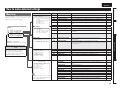
n Refer to the pages indicated below for information on connecting and playing back the various
media and external devices.
Audio and video
Playback
TV
vpage 15, 16
–
Blu-ray Disc player
vpage 15, 16
vpage 23
DVD player
vpage 15, 16
vpage 23
Set-top box (Satellite tuner or cable TV)
vpage 15, 17
–
Game console
vpage 15
–
Video cassette recorder
vpage 17
–
Digital camcorder
vpage 18
–
Connection
Playback
iPod®
vpage 19
vpage 23
USB memory device
vpage 19
vpage 24
CD player
vpage 18
vpage 23
SIRIUS satellite radio
vpage 20
vpage 25
FM/AM radio
vpage 20
vpage 27
Wireless receiver (RX101)
vpage 18
–
Audio
For speaker connections, see page 4.
12
Connection
69(16.$
1('(5/$1'6
(63$f2/
,7$/,$12
)5$1d$,6
'(876&+
(1*/,6+
Simple version
Connections
Important information
• Make connections as follows before using this unit. Select an appropriate connection type
according to the components to be connected.
• You may need to make some settings on this unit depending on the connection method. Refer to
each description for more information.
• Select the cables (sold separately) according to the components being connected.
NOTE
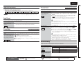
Converting input video signals for output (Video conversion function)
This unit is equipped with three types of video input connector (HDMI, Component video and video) and
three types of video output connector (HDMI, Component video and video).
Use the connectors corresponding to the components to be connected.
This function automatically converts various formats of video signals input to this unit into the formats used
to output the video signals from this unit to a monitor.
GFlow of video signalsH
This unit
Input
(IN)
Output
(MONITOR OUT)
HDMI connector
HDMI connector
HDMI
connector
Component video
connectors
Component video
connectors
Component video
connectors
Video connector
Video connector
Video connector
• HDMI signals cannot be converted into analog signals.
• When a non-standard video signal from a game machine or some other source is input, the video
conversion function might not operate.
• Component video input signals cannot be converted into Video format.
Input
Advanced version
Output
• The video conversion function supports the NTSC, PAL, SECAM, NTSC 4.43, PAL-N, PAL-M and PAL-60
formats.
• Resolutions of HDMI-compatible TVs can be checked at “HDMI Monitor Information” (vpage 61).
NOTE
Monitor
Video device
Basic version
• Do not plug in the power cord until all connections have been completed.
• When making connections, also refer to the operating instructions of the other components being
connected.
• Be sure to connect the left and right channels properly (left with left, right with right).
• Do not bundle power cords together with connection cables. Doing so can result in noise.
HDMI connector
Component video
connectors
Video connector
Information
13
(1*/,6+
'(876&+
)5$1d$,6
,7$/,$12
(63$f2/
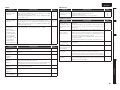
Important information
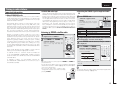
How the on-screen display appears in accordance with the video
input signal
The way the on-screen display of the menus, status, etc., is displayed differs according to the type of video
signal input to this unit.
n When video signals are input from the HDMI or component video
connector
• Menu: Switches to a screen with a black background and the menu is superimposedz.
• Status display: Not displayed.
z If you want to display the menus superimposed on the background image, input the same video signals
to the video connectors. When a menu is displayed, the picture switches to the one being input from
the video connectors and the menu is displayed superimposed over this picture.
NOTE
The menus and status display screen will not be superimposed on the video output from the component
video connector.
n When video signals are input from the video connector
• Menu: Menus are displayed superimposed over the background image.
• Status display: Displayed.
When you use the component video output connector, the on-screen display is not displayed. If you want
to display the on-screen display, connect a TV to the HDMI connector or video output connector.
Examples of on-screen display
• Status display screen
When the input source is
switched
MENU
You can connect up to four HDMI-compatible devices to the unit.
HDMI function
This unit supports the following HDMI functions:
• 3D
• Deep Color (vpage 78)
• Auto Lip Sync (vpage 58)
• x.v.Color, sYCC601 color, Adobe RGB color, Adobe YCC601color (vpage 78, 79)
• High definition digital audio format
• ARC (Audio Return Channel)
• Content Type
• CEC (HDMI control)
Copyright protection system
In order to play back digital video and audio such as BD-Video or DVD-Video via HDMI connection, both
this unit and TV or the player need to support the copyright protection system known as HDCP (Highbandwidth Digital Content Protection System). HDCP is copyright protection technology comprised of
data encryption and authentication of the connected AV device. This unit supports HDCP.
• If a device that does not support HDCP is connected, video and audio are not output correctly. Read
the owner’s manual of your television or player for more information.
• When a device supporting Deep Color signal transfer is connected, use a cable compatible “High Speed
HDMI cable” or “High Speed HDMI cable with Ethernet”
• When the ARC function is used, connect a device with a ”Standard HDMI cable with Ethernet” or “High
Speed HDMI cable with Ethernet” for HDMI 1.4a.
This function allows you to operate external devices from the receiver and operate the receiver from
external devices.
NOTE
• The HDMI control function may not work depending on the device it is connected to and its settings.
• You cannot operate a TV or Blu-ray Disc player / DVD player that is not compatible with the HDMI control
function.
[Auto]
IN :DVD
MODE:STEREO
About 3D function
Master Volume -80.0dB
Status display: The operating status appears briefly on the screen
when the input source is switched or the volume is
changed.
NOTE
When you connect a TV to this unit using the video connector, the on-screen display may not be
displayed on a TV in some cases. If the on-screen display is not displayed on your TV, set the on-screen
display output mode to "Video" mode in accordance with “Switching the on-screen display output mode”
(vpage 62).
14
Connecting an HDMI-compatible device
HDMI control function (vpage 39)
When the volume is adjusted
1.Audio Adjust
2.Information
3.Auto Setup
4.Manual Setup
5.Input Setup
[ENT]:Select
69(16.$
About HDMI cables
NOTE
• Menu screen
1('(5/$1'6
This unit supports input and output of 3D (3 dimensional) video signals of the HDMI 1.4a standards. For
playing the 3D video content, a player, and a TV that support the 3D function of the HDMI 1.4a standards
are required in addition to this unit.
69(16.$
1('(5/$1'6
(63$f2/
,7$/,$12
)5$1d$,6
'(876&+
(1*/,6+
Connecting an HDMI-compatible device
NOTE
• To enable the ARC function,set “HDMI Control” to “ON” (vpage 58).
• When connecting a TV that does not support the ARC function, a separate connection using an audio
cable is required. In this case, refer to “Connecting a TV” (vpage 16) for the connection method.
NOTE
To enable the Content type, set “Video Mode” to “Auto” (vpage 49).
NOTE
The audio signal from the HDMI output connector (sampling frequency, number of channels, etc.) may be
limited by the HDMI audio specifications of the connected device regarding permissible inputs.
Basic version
About Content Type
The HDMI Specification Version 1.4a enables simple, automated picture setting selection with no user
intervention.
• When this unit is connected to other devices with HDMI cables, connect this unit and TV also with an
HDMI cable.
• When connecting a device that supports Deep Color transmission, please use a “High Speed HDMI
cable” or “High Speed HDMI cable with Ethernet”.
• Video signals are not output if the input video signals do not match the monitor’s resolution. In this case,
switch the Blu-ray Disc/DVD player’s resolution to a resolution with which the monitor is compatible.
• When this unit and monitor are connected with an HDMI cable, if the monitor is not compatible with
HDMI audio signal playback, only the video signals are output to the monitor.
Simple version
About ARC (Audio return channel) function
The Audio Return Channel in HDMI 1.4a enables a TV, via a single HDMI cable, to send audio data
“upstream” to this unit.
Connecting to a device equipped with a DVI-D connector
Cables used for connections
When an HDMI/DVI conversion cable (sold separately) is used, the HDMI video signals are converted to
DVI signals, allowing connection to a device equipped with a DVI-D connector.
Audio and video cable (sold separately)
NOTE
HDMI cable
Blu-ray Disc
player
DVD player
Set-top box
Game
console
TV
)%.*
065
)%.*
065
)%.*
065
)%.*
065
)%.*
*/
n Settings related to HDMI connections
Set as necessary. For details, see the respective reference pages.
Advanced version
• This interface allows transfer of digital video signals and digital audio signals over a single HDMI cable.
• No sound is output when connected to a device equipped with a DVI-D connector. Make separate audio
connections.
• Signals cannot be output to DVI-D devices that do not support HDCP.
• Depending on the combination of devices, the video signals may not be output.
Input Assign (vpage 48)
Set this to change the HDMI input connector to which the input source is assigned.
HDMI Setup (vpage 58)
Make settings for HDMI video/audio output.
• Auto Lip Sync
• HDMI Audio Out
• HDMI Control
• Standby Source
• Power Off Control
Information
NOTE
The audio signals output from the HDMI connectors are only the HDMI input signals.
15
(1*/,6+
'(876&+
)5$1d$,6
,7$/,$12
(63$f2/
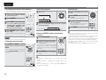
Connecting a TV
1('(5/$1'6
69(16.$
Connecting a Blu-ray Disc player / DVD player
• Select the connector to use and connect the device.
• For video connections, see “Converting input video signals for output (Video conversion function)”
(vpage 13).
• For instructions on HDMI connections, see “Connecting an HDMI-compatible device” (vpage 14).
• You can enjoy video and audio from a Blu-ray Disc or DVD.
• Select the connector to use and connect the device.
• For instructions on HDMI connections, see “Connecting an HDMI-compatible device” (vpage 14).
Cables used for connections
Video cable (sold separately)
To listen to TV audio through this device, use the optical digital connection.
Video cable
(Yellow)
NOTE
This connection is not required when a TV compatible with the ARC function (Audio Return Channel (HDMI
1.4a standard function)) is connected to this unit via an HDMI connection.
For details, see “About ARC (Audio return channel) function” (vpage 15) or refer to the instruction manual
for your TV.
Component
video cable
Video cable
Audio cable
(Yellow)
Component video
cable
(Green)
Y
Y
(Blue)
PB
PB
(Red)
PR
PR
Audio cable (sold separately)
Optical cable
Y
Y
(Blue)
PB
PB
(Red)
PR
PR
Audio cable (sold separately)
Cables used for connections
Video cable (sold separately)
(Green)
Coaxial
digital cable
(White)
L
L
(Red)
R
R
(Black)
Blu-ray Disc player
"6%*0
"6%*0
065
3
DVD player
7*%&0
7*%&0
065
"6%*0
7*%&0
$0.10/&/57*%&0
065
:
1# 13
$0.10/&/57*%&0
065
:
1# 13
7*%&0
065
$0"9*"065
"6%*0
065
3
TV
"6%*0
7*%&0
$0.10/&/57*%&0
*/
:
1# 13
Y
PB
PR
Y
PB
PR
7*%&0
*/
L
R
Y
PB
PR
Y
PB
PR
L
R
L
R
Y
PB
PR
Y
PB
PR
L
R
015*$"065
in Set as Necessary
Set this to change the digital input connector or component video input connector to which the input
source is assigned.
“Input Assign” (vpage 48)
in Set as Necessary
Set this to change the digital input connector or component video input connector to which the input
source is assigned.
“Input Assign” (vpage 48)
16
For HD audio (Dolby TrueHD, DTS-HD, Dolby Digital Plus and DTS Express) playback, connect with HDMI
(vpage 14 “Connecting an HDMI-compatible device”).
69(16.$
1('(5/$1'6
• You can watch satellite or cable TV.
• Select the connector to use and connect the device.
• For instructions on HDMI connections, see “Connecting an HDMI-compatible device” (vpage 14).
Cables used for connections
Video cable
(Yellow)
Audio cable (sold separately)
Y
Y
(Blue)
PB
PB
(Red)
PR
PR
Audio cable
(White)
L
L
(Red)
R
R
(White)
L
L
(Red)
R
R
Basic version
(Green)
Video cassette recorder
Audio cables (sold separately)
Coaxial
digital cable
(1*/,6+
Connecting a video cassette recorder
(Yellow)
Audio cable
'(876&+
Video cable (sold separately)
Video cable (sold separately)
Component
video cable
)5$1d$,6
• You can record video onto a video cassette tape.
• Select the connector to use and connect the device.
Cables used for connections
Video cable
,7$/,$12
Simple version
Connecting a set-top box (Satellite tuner/cable TV)
(63$f2/
(Black)
7*%&0
"6%*0
7*%&0
"6%*0
7*%&0
*/
"6%*0
*/
3
7*%&0
065
"6%*0
065
3
L
R
L
R
L
R
L
R
Satellite Tuner/Cable TV
7*%&0
065
$0"9*"065
"6%*0
065
3
Y
PB
PR
L
R
Y
PB
PR
L
R
Advanced version
"6%*0
7*%&0
$0.10/&/57*%&0
065
:
1# 13
in Set as Necessary
Set this to change the digital input connector or component video input connector to which the input
source is assigned.
“Input Assign” (vpage 48)
NOTE
To record video signals through this unit, use the same type of video cable for connection between this
unit and the player as used for connection between this unit and the recorder.
Information
in Set as Necessary
Set this to change the digital input connector or component video input connector to which the input
source is assigned.
“Input Assign” (vpage 48)
17
(1*/,6+
'(876&+
)5$1d$,6
,7$/,$12
Connecting a digital camcorder
• You can enjoy video and audio from a digital comcorder.
• You can enjoy games by connecting a game machine via the AUX1 input
connector. In this case, select the input source to “AUX1”.
• For instructions on HDMI connections, see “Connecting an HDMIcompatible device” (vpage 14).
Cables used for connections
(63$f2/
Connecting a wireless receiver
(RX101)
• You can enjoy CD sound.
• Select the connector to use and connect the device.
Cables used for connections
Audio cable (sold separately)
Audio cable
(Yellow)
69(16.$
Connecting a CD player
Video cable (sold separately)
Video cable
1('(5/$1'6
(White)
L
L
(Red)
R
R
By connecting a wireless receiver RX101 (sold separately) to this unit,
you can receive and playback audio signals from other devices using
the Bluetooth Communication Function.
• Use a Bluetooth device that is A2DP compatible (vpage 78 “A2DP”).
• You can also use wireless receiver RX101 as an external IR receiver.
• For instructions on the wireless receiver settings, refer to the
RX101’s operating instructions.
Optical cable
Wireless receiver RX101
Audio cable (sold separately)
Audio cable
(White)
L
L
(Red)
R
R
CD player
"6%*0
015*$"065
Optical cable
"6%*0
065
3
Digital camcorder
7*%&0
7*%&0
065
"6%*0
015*$"065
L
R
L
R
"6%*0
065
3
L
R
L
R
Bluetooth device
(A2DP Compatibility)
in Set as Necessary
NOTE
When a non-standard video signal from a game machine or some other
source is input, the video conversion function might not operate. In this
case, use the monitor output of the same connector as the input.
Set this to change the digital input connector to which the
input source is assigned.
“Input Assign” (vpage 48)
Remote control unit
You can enjoy listening to music by connecting a wireless receiver
via the M-XPort input connector. In this case, set the input source to
“M-XPort”.
NOTE
To use wireless receiver RX101 as external IR receiver, set the remote
sensor function of this unit to “DISABLE” (vpage 62 “Remote control
settings”).
18
69(16.$
1('(5/$1'6
(63$f2/
,7$/,$12
)5$1d$,6
'(876&+
(1*/,6+
Simple version
Connecting an iPod or USB memory device to the USB Port
You can enjoy music, stored on an iPod or USB memory device.
Supported iPod Models
Made for
• iPod touch (2nd generation)
• iPod touch (1st generation)
• iPod classic
• iPod with video
• iPod nano (5th generation)
• iPod nano (4th generation)
• iPod nano (3rd generation)
• iPod nano (2nd generation)
• iPod nano (1st generation)
iPod
USB memory
device
or
• iPhone
• iPhone 3G
• iPhone 3GS
Basic version
Cables used for connections
To connect an iPod to this unit, use the USB cable supplied with the iPod.
Advanced version
Marantz does not guarantee that all USB memory devices will operate or receive power. When using a
portable USB connection type HDD of the kind to which an AC adapter can be connected to supply power,
use the AC adapter.
NOTE
• USB memory devices will not work via a USB hub.
• Do not use an extension cable when connecting a USB memory device. This may cause radio interference
with other devices.
Information
19
(1*/,6+
'(876&+
)5$1d$,6
,7$/,$12
(63$f2/
1('(5/$1'6
69(16.$
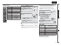
Connecting an antenna
Connecting an FM/AM antenna
Connecting a SIRIUS connector
• Connect the FM antenna or AM loop antenna supplied with the unit to enjoy listening to radio broadcasts.
• After connecting the antenna and receiving a broadcast signal (vpage 27 “Listening to FM/AM broadcasts”), fix the antenna with tape in a
position where the noise level becomes minimal.
• This unit is a SIRIUS Satellite Radio Ready® receiver. You can
receive SIRIUS® Satellite Radio by connecting to the SiriusConnect
Home Tuner and subscribing to the SIRIUS service.
• Plug the SIRIUS connector on the SIRIUS service.
• Position the Home Tuner antenna near a south-facing window to
receive the best signal.
For details, see “Listening to SIRIUS satellite radio” (vpage 25).
When making connections, also refer to the operating instructions
of the SiriusConnect Home Tuner.
Direction of broadcasting station
FM outdoor
antenna
q
w
AM loop antenna
(supplied)
e
75 Ω Coaxial
cable
SiriusConnect Home Tuner
Black
White
FM indoor
antenna
(supplied)
n Using the AM loop antenna
Suspending on a wall
Suspend directly on a wall without assembling.
AM outdoor
antenna
Ground
When
connecting
digital audio
Nail, tack, etc.
n AM loop antenna assembly
1
3XWWKHVWDQGVHFWLRQ
WKURXJKWKHERWWRPRI
WKHORRSDQWHQQDIURP
WKHUHDUDQGEHQGLW
IRUZDUG
2 ,QVHUWWKHSURMHFWLQJSDUW
LQWR WKH VTXDUH KROH LQ
WKHVWDQG
20
Standing alone
Stand
Use the procedure shown left to assemble.
Square
hole
Loop
antenna
Projecting
part
NOTE
• Do not connect two FM antennas simultaneously.
• Even if an external AM antenna is used, do not disconnect the AM
loop antenna.
• Make sure the AM loop antenna lead terminals do not touch metal
parts of the panel.
• If the signal has noise interference, connect the ground terminal
(GND) to reduce noise.
• If you are unable to receive a good broadcast signal, we recommend
installing an outdoor antenna. For details, inquire at the retail store
where you purchased the unit.
in Set as Necessary
When connecting digital of the SiriusConnect Home Tuner,
perform the setting “Digital”.
“Input Assign” (vpage 48)
69(16.$
Connecting an antenna
Keep the power cord unplugged until the SiriusConnect Home Tuner
connection have been completed.
n Positioning the antenna
For a consistent satellite signal, the antenna must be positioned
correctly. Use the following map to determine which area you are
in and position the antenna accordingly.
(63$f2/
,7$/,$12
Connect a device that has a
multichannel output terminal
)5$1d$,6
Cables used for connections
• You can use this unit as a pre-amp by connecting a commercially
available power amp to the PRE OUT connector. Adding a power amp
to each of the channels provides an even greater sound presence.
• Select the connector to use and connect the device.
Cables used for connections
Audio cable
(White)
L
L
(Red)
R
R
Audio cable
(White)
L
L
(Red)
R
R
Basic version
Audio cable (sold separately)
Audio cable (sold separately)
NORTH
(1*/,6+
Connecting a external power
amplifier
• You can connect this unit to an external device fitted with multichannel sound audio output jacks to enjoy music and video.
• The video signal can be connected in the same way as a Blu-ray Disc
player / DVD player (vpage 16 “Connecting a Blu-ray Disc player /
DVD player”).
SKY
'(876&+
Audio cable
Audio cable
WEST
q
t
w
r
EAST
Power amplifier
SUBWOOFER
FRONT
L
SUBWOOFER
R
CENTER
SURROUND
L
R
L
SURROUND
BACK
L
L
L
R
R
L
L
R
R
L
L
R
CENTER
SURROUND
L
R
SURROUND
BACK
L
R
R
HORIZON
Area 1 Point the antenna toward the sky in the east, northeast, or
southeast, either through a window or outside.
Area 2 Point the antenna toward the sky in the north or northeast,
either through a window or outside.
Area 3 Point the antenna toward the sky in the north or northwest,
either through a window or outside.
Area 4 Point the antenna toward the sky in the west, northwest, or
southwest, either through a window or outside.
Area 5 Put the antenna outside and point it straight up. The antenna
cannot be used indoors.
FRONT
L
R
L
R
L
R
L
R
L
R
L
R
Advanced version
SOUTH
AUDIO
Blu-ray Disc player / DVD player /
External decoder
AUDIO
e
Simple version
NOTE
1('(5/$1'6
R
R
When a device is connected to the SBL/SBR terminal of 7.1CH INPUT
terminals, set “Amp Assign” (vpage 56) to “Normal”.
NOTE
• When speakers have been connected to PRE OUT terminals, do not
connect the speakers to the speaker terminals.
• The output channels for the PRE OUT connector change to SBL and
SBR in the “Amp Assign” (vpage 56) settings in the menu.
21
Information
in Set as Necessary
To play analog signals input from 7.1CH INPUT terminals, set
“Input Mode” (vpage 50) to “7.1CH INPUT”.
“7.1CH INPUT” can also be selected with A/D on the remote
control unit.
• When using just one surround back speaker, connect it to the left
channel (L) terminal.
• Use the volume control on the subwoofer to control subwoofer
volume.
• If the subwoofer volume sounds low, use the volume control
provided on the subwoofer to adjust the volume.
(1*/,6+
'(876&+
)5$1d$,6
,7$/,$12
(63$f2/
1('(5/$1'6
69(16.$
Playback (Basic operation)
n Using the “Source Select” menu
n Selecting the input source (vpage 22)
n Adjusting the master volume (vpage 22)
n Turning off the sound temporarily (vpage 22)
n Playing a Blu-ray Disc player/DVD player
(vpage 23)
n Playing a CD player (vpage 23)
n Playing an iPod® (vpage 23)
n Playing a USB memory device (vpage 24)
n Tuning in radio stations (vpage 25)
Selecting a listening mode (Surround mode)
(vpage 29)
n Operating the main unit
q Press AMP and then press SOURCE SEL.
Turn INPUT SELECTOR.
• Turning INPUT SELECTOR switches the input
source, as shown below.
Display the “Source Select” menu.
Source Select
BD
USB
DVD
TV
CD
VCR
SAT
SIRIUS
GAME
TUNER
AUX1
M-XPort
[
]:Source The currently selected input source
[ENT]:Select is highlighted.
w Use uio p to select the input source,
then press ENTER.
SAT
SIRIUS
GAME
CD
AUX1
TV
USB
Adjusting the master volume
8VHVOLUME + –WRDGMXVWWKHYROXPH
GAdjustable rangeH 0.0 – 99.0
• The adjustable range may vary depending on input signal and
channel level settings.
Also refer to the operating instructions of the connected components
when playing them.
Selecting the input source
n Operating the remote control unit
Press INPUT d f.
• When INPUT d f is pressed, the
input source is switched in the order
shown below.
BD
M-XPort
DVD
TUNER
VCR
SAT
SIRIUS
3UHVVMUTE
GAME
CD
You can also operate via the main unit.
In this case, perform the following
operations.
Turn VOLUME to adjust the volume.
Turning off the sound temporarily
The desired input source can be selected
directly.
You can also use the following operation to select an input
source.
VCR
n When the “Volume Display” setting (vpage 60) is
“Absolute”
• When using with an iPod connected directly to the USB port of this
unit, select “USB” for the input source.
• Input sources that are not going to be used can be set ahead of time.
Make this setting at “Source Delete” (vpage 60).
• To turn off the source selection menu without selecting an input
source, press SOURCE SEL again.
3UHVV WKH LQSXW VRXUFH VHOHFW EXWWRQ
BD DVD VCR SAT GAME AUX1
USB TV CD SATR TUNE M-XP
WZLFHWRSOD\EDFNWKDWVRXUFH
TUNER
GAdjustable rangeH
–––
–80.5dB – 18.0dB
Important information
NOTE
DVD
n When the “Volume Display” setting
(vpage 60) is “Relative”
The input source is set and the source
selection menu is turned off.
Playback (Advanced operation) (vpage 39)
Before starting playback, make the connections between the different
components and the settings on the receiver.
BD
M-XPort
AUX1
TV
USB
• The sound is reduced to the level set at “Mute Level” (vpage 60).
• To cancel, press MUTE again. Muting can also be canceled by
adjusting the master volume.
22
69(16.$
The following describes the procedure for playing Blu-ray Disc player/
DVD player.
1
3UHSDUHIRUSOD\EDFN
q Turn on the power of the TV,
4 3OD\WKHFRPSRQHQWFRQQHFWHGWRWKLVXQLW
Make the necessary settings on the player (language setting,
subtitles setting, etc.) beforehand.
The following describes the procedure for playing CD player.
3UHSDUHIRUSOD\EDFN
q Turn on the power of the
subwoofer and player.
w Load the disc in the player.
2
3UHVVCDWZLFHWRVZLWFKWKH
3 LQSXWVRXUFHWRWKH&'SOD\HU
4 3OD\WKHFRPSRQHQWFRQQHFWHGWRWKLVXQLW
3UHVVONWRWXUQRQSRZHUWR
WKHXQLW
'(876&+
(1*/,6+
6 3UHVVENTERpRU1
Listening to music on an iPod®
Playback starts.
WRWKH86%
1 &RQQHFWWKHL3RG
SRUWvSDJH³&RQQHFWLQJDQ
L3RGRU86%PHPRU\GHYLFHWR
WKH86%3RUW´
• You can specify the duration of the on-screen display to be
displayed (default: 30 sec) at menu “USB” (vpage 60). Press
uio p to return to the original screen.
• To play back compressed audio with extended
bass or treble reproduction, we recommend
playback in M-DAX mode (vpage 55). The
default setting is “OFF”.
• In Remote mode, press STATUS during playback
to check the title name, artist name, and album
name.
3UHVVONWRWXUQRQSRZHUWRWKH
2 XQLW
3UHVVUSBWZLFHWRVZLWFKWKH
3 LQSXWVRXUFHWR³86%´
NOTE
If the connections screen is not displayed,
the iPod may not be properly connected.
Reconnect it.
4
iPod operation
3UHVV SEARCH DQG KROG LW GRZQ IRU VHFRQGV RU
PRUHWRVHOHFWWKHGLVSOD\PRGH
• There are two modes for displaying the contents recorded on the
iPod.
Remote mode
Display iPod information on the TV screen.
• English letters, numbers and certain
symbols are displayed. Incompatible
characters are displayed as “.”
(period).
• In “Remote mode”, the iPod display is
OK to disconnect.
as shown at right.
Playable Music file
files
Video file
iPod®
3
Page search mode
SEARCH
(Press and hold)
Direct/Remote mode switching
RETURN
Return
Manual search
(fast-reverse/fast-forward)
Direct mode
1
8 9
3
2
REPEAT
RANDOM
3
TV POWER
Playback / Pause
Auto search (cue)
Pause
Stop
Repeat playback
Shuffle playback
TV power on/standby
(Default : Marantz)
Switch TV input
(Default : Marantz)
z
3
SEARCH
(Press and release)
3
3
z Only the sound is played.
uiWRVHOHFWWKHLWHPWKHQSUHVVENTERRUpWR
5 8VH
VHOHFWWKH¿OHWREHSOD\HG
TV INPUT
Repeat playback and shuffle playback can also be set from
“Input Setup” – “Playback Mode” (vpage 51) in the menu.
NOTE
• Depending on the type of iPod and the software version, some
functions may not operate.
• Note that Marantz will accept no responsibility whatsoever for any
problems arising with the data on an iPod when using this unit in
conjunction with the iPod.
23
Information
Active
buttons
Remote
control unit
(This unit)
Remote mode
Function
Cursor operation
Enter
6 7
(Press and hold)
Direct mode
Display iPod information on the iPod screen.
• “Direct iPod” is displayed on the display of this unit.
Display mode
Operation buttons
uio p
ENTER
Advanced version
Playing a CD player
)5$1d$,6
Basic version
3UHVVONWRWXUQRQSRZHUWR
2 WKHXQLW
3UHVVBDRUDVDWZLFHWRVZLWFK
3 WKHLQSXWVRXUFHIRUWKHSOD\HU
XVHGIRUSOD\EDFN
1
You can play back both video, photo and audio.
subwoofer and player.
this unit.
,7$/,$12
Playing an iPod®
w Change the TV input to the input of
e Load the disc in the player.
(63$f2/
Simple version
Playing a Blu-ray Disc player/DVD
player
1('(5/$1'6
(1*/,6+
'(876&+
)5$1d$,6
,7$/,$12
(63$f2/
1('(5/$1'6
69(16.$
Playing a USB memory device
Playing back music files recorded on a USB memory device.
Playing files stored on USB memory
devices
Important information
n USB memory devices
A USB memory device can be connected to the USB port of this
unit to play music files stored on the USB memory device.
• Only USB memory devices conforming to mass storage class can
be played on this unit.
• This unit is compatible with USB memory devices in “FAT16” or
“FAT32” format.
GCompatible formatsH
USB memory devices z1
WMA (Windows Media Audio)
3z2
MP3 (MPEG-1 Audio Layer-3)
3
MPEG-4 AAC
3z3
WAV
3
1 &RQQHFWWKH86%PHPRU\
GHYLFHWRWKH86%SRUW
vSDJH³&RQQHFWLQJDQL3RG
RU86%PHPRU\GHYLFHWRWKH
86%3RUW´
3UHVVUSBWZLFHWRVZLWFKWKH
2 LQSXWVRXUFHWR³86%´
ui WR VHOHFW WKH VHDUFK
3 3UHVV
LWHPRUIROGHUWKHQSUHVVENTER
RUp
z1 USB
• This unit is compatible with MP3 ID3-Tag (Ver. 2) standards.
• This unit is compatible with WMA META tags.
z2 Copyright-protected files can not be played.
z3 Only files that are not protected by copyright can be played on
this unit.
Also, files encoded in WMA format when ripped from a CD, etc.
on a computer may be copyright protected, depending on the
computer’s settings.
GCompatible formatsH
uiWRVHOHFWWKH¿OHWKHQ
4 3UHVV
SUHVVENTERpRU1
Playback starts.
• You can specify the duration of the on-screen display to be displayed
(default: 30 sec) at menu “USB” (vpage 60). Press uio p to
return to the original screen.
• To play back compressed audio with extended bass or treble
reproduction, we recommend playback in M-DAX mode
(vpage 55). The default setting is “High”.
• If the USB memory device is divided into multiple partitions, only the
top partition can be selected.
• This unit is compatible with MP3 files conforming to “MPEG-1 Audio
Layer-3” standards.
NOTE
• Note that Marantz will accept no responsibility whatsoever for any
problems arising with the data on a USB memory device when using
this unit in conjunction with the USB memory device.
• USB memory devices will not work via a USB hub.
• Marantz does not guarantee that all USB memory devices will
operate or be supplied power. When using a USB portable hard disk
that can draw power from an AC adapter, we recommend using the
AC adapter.
• It is not possible to connect and use a computer via the USB port of
this unit using a USB cable.
n USB operation
Operation buttons
uio p
ENTER
SEARCH
RETURN
Function
Cursor operation
Enter
Page search
Return
Sampling
frequency
Bit rate
or
Bit length
Extension
6 7
(Press and hold)
Manual search
(fast-reverse/fast-forward)
WMA (Windows
Media Audio)
32/44.1/48 kHz
48 – 192 kbps
.wma
MP3 (MPEG-1
Audio Layer-3)
32/44.1/48 kHz
32 – 320 kbps
.mp3
MPEG-4 AAC
32/44.1/48 kHz
16 – 320 kbps
.m4a
WAV
32/44.1/48 kHz
16 bit
.wav
1
8 9
3
2
REPEAT
RANDOM
Playback/Pause
Auto search (cue)
Pause
Stop
Repeat playback
Shuffle playback
TV power on/standby
(Default : Marantz)
Switch TV input
(Default : Marantz)
TV POWER
TV INPUT
Repeat playback and shuffle playback can also
be set from “Input Setup” – “Playback Mode”
(vpage 51) in the menu.
24
69(16.$
1('(5/$1'6
(63$f2/
,7$/,$12
)5$1d$,6
'(876&+
(1*/,6+
Important information
n About SIRIUS XM radio
To listen to Satellite Radio, you’ll need to connect either a SIRIUS
or XM Satellite Radio tuner (sold separately) to your satellite-ready
receiver. Satellite Radio is available to residents of the US (except
Alaska and Hawaii) and Canada.
Listening to SIRIUS satellite radio
SATRWZLFHWRVZLWFKWKH
1 3UHVV
LQSXWVRXUFHWR³6,5,86´
TUNING +RU TUNING –WR
2 8VH
VHOHFWWKHFKDQQHO
When the channel is tuned in, the
name of the song and artist are
displayed.
Family friendly packages are also available to restrict channels
featuring content that may be inappropriate for children.
STATUSXQWLO
1 3UHVV
³6,*1$/´DSSHDUVRQWKH
GLVSOD\
The display will switch as shown
below, depending on the reception
conditions.
Display
EXCELLENT
GOOD
WEAK
NO SIGNAL
Status
Signal strength is excellent
Signal strength is good
Signal strength is weak
No signal
WKH SRVLWLRQ RI WKH DQWHQQD XQWLO ³6,*1$/
2 $GMXVW
(;&(//(17´LVVKRZQRQWKHGLVSOD\
3UHVVSTATUSXQWLOWKHFKDQQHOH[DPSOH³65´
3 LVGLVSOD\HG
3UHVVTUNING +RUTUNING –
4 DQGVHOHFWFKDQQHO65
Channel No. and Sirius ID are alternately
shown on the display.
To subscribe to XM, U.S. customers should visit xmradio.com
or call 1-800-XMRADIO (1-800-967-2346); Canadian customers
should visit xmradio.ca or call XM Listener Care at 1-877-GETXMSR
(1-877-438- 9677).
To subscribe to SIRIUS, U.S. and Canadian customers can
call 1-888-539-SIRI (1-888-539-7474) or visit sirius.com (US) or
siriuscanada.ca (Canada).
n Checking the SIRIUS signal strength and radio
ID
Advanced version
Whether you purchase a SIRIUS or XM tuner, you’ll need to
activate and subscribe to begin enjoying the service. Easy to follow
installation and setup instructions are provided with the satellite
tuners. Whichever service you choose, there are a variety of
programming packages available, including the option of adding
“The Best of SIRIUS” programming to your XM tuner or “The Best
of XM” programming to your SIRIUS tuner, enabling you to enjoy
the most popular programming among both services. The “Best
of” packages are not available to SIRIUS or XM Canada subscribers
at this time.
SIRIUS, XM and all related marks and logos are trademarks of Sirius
XM Radio Inc. and its subsidiaries. All other marks and logos are the
property of their respective owners. All rights reserved. SIRIUS and
XM subscriptions sold separately. Taxes and a one-time activation
fee may apply. XM tuners and home docks or SIRIUS tuners (each
sold separately) are required to receive the SIRIUS or XM satellite
radio service. All programming and fees subject to change. It is
prohibited to copy, decompile, disassemble, reverse engineer,
hack, manipulate or otherwise make available any technology or
software incorporated in receivers compatible with the SIRIUS or
XM Satellite Radio Systems. Service not available in Alaska and
Hawaii.
Basic version
Satellite Radio delivers a variety of commercial-free music from
categories ranging from Pop, Rock, Country, R&B, Dance, Jazz,
Classical and many more plus coverage of all the top professional
and college sports including play by play games from select
leagues and teams. Additional programming includes expert sports
talk, uncensored entertainment, comedy, family programming,
local traffic and weather and news from your most trusted sources.
n SIRIUS XM radio legal
Simple version
Tuning in radio stations
SR000 SiriusID
************
Sirius ID :
The strength of both the SIRIUS satellite and terrestrial signals can be
checked “Antenna Aiming” (vpage 47).
25
Information
• The channel switches continuously when TUNING + or TUNING – is
pressed and held.
• You can specify the duration of the on-screen display to be displayed
(default: 30 sec) at menu “TUNER” (vpage 60). Press uio p to
return to the original screen.
• The song title, artist name, composer name,
category and reception level can be checked by
pressing STATUS.
Sirius ID
• Write your own SIRIUS ID for storage use.
(1*/,6+
'(876&+
)5$1d$,6
,7$/,$12
(63$f2/
1('(5/$1'6
69(16.$
Tuning in radio stations
n Presetting radio channels (Preset memory)
Your favorite broadcast channels can be preset so that you can
tune them in easily. Up to 56 channels can be preset.
LQ WKH EURDGFDVW FKDQQHO
1 7XQH
\RXZDQWWRSUHVHW
2 3UHVVMEMORY
SHIFT WR VHOHFW WKH EORFN
3 3UHVV
$ WR * LQ ZKLFK WR SUHVHW WKH
FKDQQHO WR SHU EORFN WKHQ
SUHVVPRESET +PRESET –RU1 –
8WRVHOHFWWKHSUHVHWQXPEHU
MEMORYDJDLQWRFRPSOHWH
4 3UHVV
WKHVHWWLQJ
• To preset other stations, repeat steps 1 to
4.
NOTE
Preset channels are erased by overwriting them.
n Listening to preset channels
3UHVV PRESET + PRESET – WR VHOHFW
WKHGHVLUHGSUHVHWFKDQQHOWKHQSUHVV
ENTER
• Preset channels can also be selected by
pressing SHIFT/TOP MENU (Block) and 1 –
8 (Channel).
n Searching categories
n Parental Lock
1 3UHVVop
1 7XQHWRWKHFKDQQHO\RXZDQWWR
ORFN
3UHVV ENTER IRU DW OHDVW 2 VHFRQGV
CATEGORY SEARCH
“Enter Lock Code” is displayed.
CAT: Pops
Channel category
opWRVHOHFWWKHFDWHJRU\WRXVHuiWRVHOHFW
2 8VH
WKHGHVLUHGFKDQQHO
Channel category
Pops SR001
Channel
n Accessing SIRIUS satellite radio channels
directly
1 3UHVVSEARCH/INFO
2 3UHVV0 – 9WRLQSXWWKHFKDQQHO
Example: Accessing channel “SR123”:
Press 1, 2 and 3.
• If no button is pressed within several
seconds,
the
channel
automatically
switches to the one whose number has
been input.
3 3UHVVENTERWRVHWWKDWFKDQQHO
Reception switches to the selected
channel.
• “UPDATING” is displayed while the encording code is being
updated.
• “SIRIUS UPDATING” is displayed when updating SIRIUS tuner
firmware.
• Refer to “Troubleshooting” – “SIRIUS Satellite Radio” (vpage 81)
regarding other messages.
26
3 (QWHUWKHGLJLWORFNFRGHXVLQJ
uiopRU0 – 9
When you enter the correct code, the
corresponding channel is locked.
4 3UHVVENTER
• Channels under Parental Lock cannot be tuned in by performing
channel up/down or by category search.
• Channels stored in preset memory can be tuned in by the preset
channel select operation, even if Parental Lock is applied.
• When a channel to which Parental Lock is applied is being played,
Parental Lock for that channel is cancelled by performing step 2.
• See “Edit Lock Cord” (vpage 47) for the method of changing
Parental Lock Cord.
• You can also set “Parental Lock” (vpage 47) from the menu.
69(16.$
1('(5/$1'6
(63$f2/
,7$/,$12
)5$1d$,6
'(876&+
(1*/,6+
Tuning in radio stations
Listening to FM/AM broadcasts
Operation buttons
Function
PRESET +, –
Preset channel selection
Cursor operation / Category search
uio p
ENTER
To parental lock password check screen
(Press and hold)
Direct search
Return
Channel selection
0–9
Preset channel selection (1 – 8) /
Channel direct call
SHIFT
MEMORY
TV POWER
TV INPUT
Preset channel block selection
Preset memory registration
TV power on/standby
(Default : Marantz)
Switch TV input
(Default : Marantz)
FM
When listening to an FM broadcast.
AM
When listening to an AM broadcast.
3 7XQHLQWKHGHVLUHGEURDGFDVW
VWDWLRQ
q To tune in automatically (Auto tuning)
Press T.MODE to light the “AUTO” indicator on the display, then
use TUNING + or TUNING – to select the station you want to
hear.
• Stations can be preset automatically at “Auto Preset”
(vpage 47). If “Auto Preset” is performed after performing
“Manual Preset”, the “Manual Preset” settings will be overwritten.
1 7XQHLQWKHEURDGFDVWVWDWLRQ\RX
ZDQWWRSUHVHW
2 3UHVVMEMORY
SHIFT/TOP MENUWRVHOHFW
3 3UHVV
WKHEORFN$WR*LQZKLFKWR
SUHVHWWKHFKDQQHOWRSHU
EORFNWKHQSUHVVPRESET +
PRESET –RU 1 – 8WRVHOHFWWKH
SUHVHWQXPEHU
MEMORYDJDLQWRFRPSOHWH
4 3UHVV
WKHVHWWLQJ
Advanced version
w To tune in manually (Manual tuning)
Press T.MODE to turn off the display’s “AUTO” indicator, then use
TUNING + or TUNING – to select the station you want to hear.
Your favorite broadcast stations can be preset so that you can tune
them in easily. Up to 56 stations can be preset.
Basic version
SEARCH
RETURN
TUNING +, –
1
3UHVV BAND WR VHOHFW ³)0´ RU
2 ³$0´
3UHVVTUNEWZLFHWRVZLWFKWKH
LQSXWVRXUFHWR³781(5´
n Presetting radio stations (Manual preset)
• To preset other stations, repeat steps 1 to 4.
• If the desired station cannot be tuned in with auto tuning, tune it in
manually.
• When tuning in stations manually, press and hold TUNING + or
TUNING – to change frequencies continuously.
• You can specify the duration of the on-screen display to be displayed
(default: 30 sec) at menu “TUNER” (vpage 60). Press uio p to
return to the original screen.
Simple version
n SIRIUS operation
Default settings
Block (A – G)
and
Channel (1 – 8)
A1 – A8
B1 – B8
C1 – C8
D1 – D8
E1 – E8
F1 – F8
G1 – G8
Default Settings
87.5 / 89.1 / 98.1 / 107.9 / 90.1 / 90.1 / 90.1 /
90.1 MHz
520 / 600 / 1000 / 1400 / 1710 kHz,
90.1 / 90.1 / 90.1 MHz
90.1 MHz
90.1 MHz
90.1 MHz
90.1 MHz
90.1 MHz
Information
Specify a name for the preset broadcast station
(Preset Name) (vpage 48)
27
(1*/,6+
'(876&+
)5$1d$,6
,7$/,$12
(63$f2/
1('(5/$1'6
69(16.$
Tuning in radio stations
n Listening to preset stations
3UHVV SHIFT/TOP MENUWRVHOHFW
1 WKHPHPRU\EORFN$WR*
PRESET + PRESET – RU
2 3UHVV
1 – 8 WR VHOHFW WKH GHVLUHG SUHVHW
FKDQQHO
n Tuner (FM/AM) operation
Operation buttons
PRESET +, –
uio p
ENTER
SEARCH
BAND
T.MODE
TUNING +, –
0–9
SHIFT
MEMORY
TV POWER
TV INPUT
You can also operate via the main unit. In this
case, perform the following operations.
Press o p to select the preset radio station.
Switching the tuning increment
Function
Preset channel selection
Cursor operation
Enter
Direct frequency tuning
FM/AM switching
Switch search modes
Tuning (up/down)
Preset channel selection (1 – 8) /
Direct frequency tuning (0 – 9)
Preset channel block selection
Preset memory registration
TV power on/standby
(Default : Marantz)
Switch TV input
(Default : Marantz)
The tuning increment factory settings are 9kHz for AM, and 0.05
MHz for FM.
ON/STANDBY
AUTO
DISPLAY
o p
:KLOHSUHVVLQJGRZQAUTODQGDISPLAYSUHVVON/
1 STANDBY
WRWXUQRQWKHSRZHU
“Step 0 AM9/FM50 1” appears on the display.
2 3UHVVop
“Step 0 AM10/FM200 1” appears on the display, and the
tuning increment is switched to AM and FM are 10 kHz and
0.2 MHz.
n Direct frequency tuning
You can enter the receiving frequency directly to tune in.
1
2 ,QSXWIUHTXHQFLHVXVLQJWKH0±9
3UHVVSEARCH/INFO
• If o is pressed, the immediately preceding
input is cancelled.
VHWWLQJ LV FRPSOHWHGSUHVV
3 :KHQ
ENTER
The preset frequency is tuned in.
28
3 3UHVVON/STANDBY
• The tuner preset memory will be cleared if this operation is
performed.
• This setting will not revert to the default values even when the
microprocessor is reset.
69(16.$
1('(5/$1'6
(63$f2/
,7$/,$12
)5$1d$,6
'(876&+
(1*/,6+
This unit can play input audio signals in multi-channel surround mode or in stereo mode.
Select a listening mode suitable for the playback contents (cinema, music, etc.) or according to your liking.
Multi-channel playback
Listening mode
Input audio signal
n Surround playback of 2-channel sources
Playback
Listening mode
Multi-channel playback
(vpage 29)
Surround
Multi channel
2-channel
Stereo
Multi channel
Stereo
Multi channel
Surround
Multi channel
Virtual
Surround
Stereo playback
(vpage 31)
• If multichannel signals are input, they are mixed down to 2-channel
audio and are played.
• Subwoofer signal is also output.
Direct playback
(vpage 31)
Sound recorded in source is played as is.
• Surround back signals or front height signals are not created.
• In this mode, the following items cannot be adjusted.
• Tone (vpage 53)
• MultEQ® (vpage 53)
• Dynamic EQ® (vpage 54) • Dynamic Volume® (vpage 54)
• M-DAX (vpage 55)
Dolby Virtual Speaker/
Dolby Headphone
playback (vpage 31)
Virtual Surround processing is performed on 2-channel or
multichannel input signals that are played back.
• Some listening modes cannot be selected, depending on the audio format or number of channels of the input
signal. For details, see “Types of input signals, and corresponding surround modes” (vpage 76).
• Adjust the sound field effect with the menu “Surround Parameter” (vpage 52) to enjoy your favorite sound mode.
• You can select the listening mode by pressing SURROUND MODE on the main unit.
Press SURROUND MODE and the modes are switched as shown below.
AUTO*(STEREO)
DOLBY PLgz
NEURAL
DOLBY PLg(x) Movie
MULTI CH STEREO
zFor “AUTO”, press AUTO on the amplifier or remote control.
DOLBY PLg(x) Music
DTS NEO:6 music
DOLBY PLg(x) Game
DTS NEO:6 cinema
VRXQG
• Each time SURR. is pressed, the surround mode is switched.
Which decoder can be selected depends on the settings of “Amp
Assign” (vpage 56) or “Speaker Config.” (vpage 56).
DOLBY PLgz
z1 This mode is for 7.1-channel surround playback using
DOLBY PLgx
z2 This mode is for 7.1-channel or 6.1-channel surround
DOLBY PLg
DTS NEO:6
MULTI CH
STEREO
NEURAL
the front height speakers.
• “PLgz Height” is displayed.
playback using the surround back speakers.
• “PLgx Movie”, “PLgx Music”or “PLgx Game” is
displayed.
This mode is for 5.1-channel surround playback. Select
this mode if no front height speaker nor surround back
speaker is to be used.
• “PLg Movie”, “PLg Music”or “PLg Game” is
displayed.
This mode is for 7.1-channel, 6.1-channel or
5.1-channel surround playback using the surround
back speakers.
• “DTS NEO:6 Cinema” or “DTS NEO:6 Music” is
displayed.
This mode is for enjoying stereo sound from all
speakers.
z3 This mode is for 7.1-channel, 6.1-channel or
5.1-channel surround playback using the surround
back speakers.
• “NEURAL” is displayed.
z1 This can be selected when the “Amp Assign” (vpage 56) setting
in the menu is set to “Normal”, and the “Front Speaker Setup”
setting (vpage 58) is set to “A”.
This cannot be selected when the “Speaker Config.” – “Front
Height” is set to “None”.
z2 This can be selected when “Amp Assign” is set to “Normal” or
“Speaker Config.” – “S.Back” is not set to “None”.
z3 This mode supports analog 2-channel audio, and linear PCM 2
channel (44.1 kHz, 48 kHz) audio.
29
Information
DOLBY VIRTUAL
STEREO
1 3OD\LQJWKHVRXUFHvSDJH–
SURR.WRVHOHFWWKHVXUURXQG
2 3UHVV
GHFRGHUWRSOD\EDFNPXOWLFKDQQHO
Advanced version
2-channel
For 2-channel signal input:
• Surround-channel signals are created and played with surround
playback.
For multichannel signal input:
• The surround signal recorded in source is played as surround
playback. (The sound is played according to the settings of the
speaker size in “Speaker Config.” (vpage 56).)
• Surround-back-channel or front-height-channel signals that are not
recorded in source can be created.
Basic version
2-channel
2-channel
Simple version
Selecting a listening mode (Surround mode)
(1*/,6+
'(876&+
)5$1d$,6
,7$/,$12
(63$f2/
1('(5/$1'6
69(16.$
Multi-channel playback
n Surround playback of multi-channel sources
(Dolby Digital, DTS etc.)
3OD\LQJWKHVRXUFHvSDJH–
1 3UHVVSURR.WRVHOHFWWKH
2 VXUURXQGGHFRGHUWRSOD\EDFN
PXOWLFKDQQHOVRXQG
Select the surround mode while viewing the display on the
screen (v“Displaying the currently playing surround mode”
at right).
• Which decoder can be selected depends on the input signal,
the settings of “Amp Assign” (vpage 56) or “Speaker Config.”
(vpage 56).
Displaying the currently playing surround mode
Input signal
DOLBY DIGITAL
(2ch)
DOLBY DIGITAL
(other than 2ch) /
DOLBY DIGITAL EX
DOLBY DIGITAL Plus
DOLBY TrueHD
DTS (5.1ch) /
DTS-ES Discrete 6.1 /
DTS-ES Matrix 6.1 /
DTS 96/24
DTS-HD
PCM (multi ch)
All Input signal
Surround mode
Display
q
w
NEURAL
NEURAL
DOLBY DIGITAL
DOLBY DIGITAL EX
DOLBY DIGITAL + PLgx Movie
DOLBY DIGITAL + PLgx Music
DOLBY DIGITAL + PLgz
DOLBY DIGITAL Plus
DOLBY DIGITAL Plus + EX
DOLBY DIGITAL Plus + PLgx
Movie
DOLBY DIGITAL Plus + PLgx
Music
DOLBY DIGITAL Plus + PLgz
DOLBY TrueHD
DOLBY TrueHD + EX
DOLBY TrueHD + PLgx Movie
DOLBY TrueHD + PLgx Music
DOLBY TrueHD + PLgz
DTS SURROUND
DTS + PLgx Movie
DTS + PLgx Music
DTS + PLgz
DTS + NEO:6
DTS ES MTRX6.1z1
DTS ES DSCRT6.1z2
DTS 96/24z3
DTS-HD HI RES
DTS-HD MSTR
DTS-HD + NEO:6
DTS-HD + PLgx Movie
DTS-HD + PLgx Music
DTS-HD + PLgz
DTS Express
MULTI CH IN
MULTI IN + Dolby EX
MULTI IN + PLgx Movie
MULTI IN + PLgx Music
MULTI IN + PLgz
MULTI CH IN 7.1
Dolby VIRTUAL SPEAKER
DOLBY DIGITAL
DOLBY DIGITAL EX
D+ PL x Movie
D+ PL x Music
DOLBY D
PL z
DOLBY DIGITAL +
DOLBY D +
EX
D + + PL x Mv
q Shows a decoder to be used.
D + + PL x Ms
DOLBY D +
PL z
DOLBY TrueHD
DOLBY HD EX
HD +PL x Mv
HD +PL x Ms
DOLBY HD PL z
DTS SURROUND
DTS
PL x Mv
DTS
PL x Ms
DTS
PL z
DTS
NEO:6
DTS ES MTRX6.1
DTS ES DSCRT6.1
DTS 96/24
DTS-HD HI RES
DTS-HD MSTR
DTS-HD
NEO:6
DTS-HD
PL x Mv
DTS-HD
PL x Ms
DTS-HD
PL z
DTS Express
MULTI CH IN
MULTI Dolby EX
MULTI IN PL x Mv
MULTI IN PL x Ms
MULTI IN PL z
MULTI CH IN 7.1
DOLBY VS
For an input signal that can be reproduced in
each surround mode, see “Surround modes and
surround parameters” (vpage 74).
z1 This is displayed when the input signal is “DTS-ES Matrix 6.1”.
z2 This is displayed when the input signal is “DTS-ES Discrete 6.1”.
z3 This is displayed when the input signal is “DTS 96/24”.
30
GViews on the displayH
• A DOLBY DIGITAL Plus decoder is displayed
as “DOLBY D +”.
w Shows a decoder that creates sound output
from the surround back speakers.
• “+ PLgz” indicates the front height sound
from front height speakers.
69(16.$
This is the mode for playing in stereo. The tone can be adjusted.
• Sound is output from the front left and right speakers and subwoofer.
• If multichannel signals are input, they are mixed down to 2-channel
audio and are played.
Stereo playback begins.
,7$/,$12
Direct playback
Sound recorded in source is played as is.
• Surround back signals or front height signals are not created.
• In this mode, the following items cannot be adjusted.
• Tone (vpage 53)
• MultEQ® (vpage 53)
• Dynamic EQ® (vpage 54) • Dynamic Volume® (vpage 54)
• M-DAX (vpage 55)
1 3OD\LQJWKHVRXUFHvSDJH
–
3UHVVP.DIRECTWRVHOHFWWKH
2 GLUHFWPRGH
• If PURE DIRECT on the main unit is
pressed, the same function as with the
remote control unit can be obtained.
)5$1d$,6
'(876&+
(1*/,6+
Dolby Virtual Speaker/Dolby
Headphone playback
Dolby Virtual Speaker mode
This delivers a full surround sound experience from two stereo
speakers.
• Sound is output from the front left and right speakers.
• If multichannel signals are input, they are mixed down to 2-channnel
audio.
3OD\LQJWKHVRXUFHvSDJH–
1 3UHVVSURR.WRVHOHFW³'2/%<
2 96´
Basic version
1
2 3UHVVSTEREO
3OD\LQJWKHVRXUFHvSDJH–
(63$f2/
Simple version
Stereo playback
1('(5/$1'6
Dolby Headphone mode
You can enjoy listening to multi-channel surround sound through
headphones using this mode.
Source Direct
This mode plays back tracks at high sound
quality without passing through the sound quality
adjustment circuits.
Pure Direct z This mode plays back tracks at the closest to the
original sound quality.
Auto
This mode detects the type of input digital signal,
and automatically selects the corresponding mode
for playback.
zThe following circuits that affect sound quality are set to off.
• Main unit’s display circuit (The display is turned off.)
• Analog video input/output circuit
NOTE
When in the PURE DIRECT mode, the menu screen is not displayed.
• Each time SURR. is pressed, the Dolby Headphone mode is
switched.
This is the surround mode for listening with
DOLBY
HEADPHONE headphones.
The surround sound field is played through regular
headphones.
DOLBY HP
BYPASS
The sound is played in the normal stereo mode
rather than the surround mode when listening with
headphones.
DOLBY HP
PLg Movie
This mode is best suited for movie sources.
DOLBY HP
PLg Music
This mode is best suited for music sources.
NOTE
• The surround mode returns to the previous setting as soon as the
plug is removed from the jack.
• In headphone mode, Tone Control is not available.
• You can select Dolby HP PLⅡ Movie or Dolby HP PLⅡ Music
when a 2-channel source is played back.
31
Information
• To cancel, press P. DIRECT again.
• Video signals are only output when HDMI signals are played in the
PURE DIRECT mode.
3UHVVSURR.WRVHOHFWWKH'ROE\
+HDGSKRQHPRGH
Advanced version
• Each time P.DIRECT is pressed, the direct mode is switched.
(1*/,6+
'(876&+
)5$1d$,6
,7$/,$12
(63$f2/
1('(5/$1'6
69(16.$
Advanced
version
Advanced version
Here, we explain functions and operations that let you make better use of this unit.
F Speaker installation/connection (Other than 7.1-channel system with surround
back speakers) vpage 33
F Connections (Advanced connection) vpage 38
F Playback (Advanced operation) vpage 39
F How to make detailed settings vpage 43
F Other settings vpage 62
F Operating the connected devices by remote control unit vpage 63
32
69(16.$
1('(5/$1'6
(63$f2/
,7$/,$12
)5$1d$,6
'(876&+
(1*/,6+
This section explains a wide range of speaker installation/connection/setting procedures.
For details on installing/connecting/setting 7.1 channel audio that uses surround back speakers, see “Simple version (Simple setup guide)” (vpage 3).
Use the Audyssey® Auto Setup function of this unit to automatically detect the number of connected speakers and perform optimal settings for the speakers to
be used.
When 7.1ch (Front height speaker) installed
Procedure for speaker settings
FHL
When 5.1ch installed
Basic version
Install
FHR
FL
FR
FL SW
Connect (vpage 34)
Simple version
Speaker installation/connection (Other than 7.1-channel system with surround back speakers)
FR
SW
C
C
z2
z1
z1
z2
z3
Set up speakers (vpage 37)
SL
SR
SR
Listening
position
Listening position
This unit is compatible with Dolby Pro Logic gz (vpage 78),
which offers an even wider and deeper surround sensation.
When using Dolby Pro Logic gz, install front height speakers.
z1 22˚ – 30˚
z2 22˚ – 45˚
z1 22˚ – 30˚
z3 90˚ – 110˚
When 6.1ch (Surround back speaker) installed
Advanced version
Install
SL
z2 120˚
When 2.1ch installed
Install the surround back speakers in a position 2 to 3 ft (60 to 90 cm)
higher than ear level.
Front height
speaker
• Point slightly
downwards
At least
3.3 ft / 1 m z
FL
Surround
speaker
FR
SW
FL
SW
FR
C
z2
z1
2 – 3 ft /
60 – 90 cm
SL
SR
GViewed from the sideH
Listening position
z Recommended for Dolby Pro Logic gz
SB
NOTE
It is not possible to use the surround back speakers and front height
speakers simultaneously.
z1 22˚ – 30˚
z2 90˚ – 110˚
Information
Surround back
speaker
• Point slightly
downwards
Front
speaker
Listening position
FL
FR
C
SW
SL
SR
Front speaker (L)
Front speaker (R)
Center speaker
Subwoofer
Surround speaker (L)
Surround speaker (R)
SB Surround back speaker
FHL Front height speaker (L)
FHR Front height speaker (R)
33
(1*/,6+
'(876&+
)5$1d$,6
,7$/,$12
(63$f2/
1('(5/$1'6
69(16.$
Connect
• For the method of connecting the 7.1-channel system with surround back speakers, see page 4.
• For the method of connecting the TV, see page 5.
7.1-channel (Front height speaker) connection
For 7.1-channel (Front height speaker) playback, set “Amp Assign” in “Set up speakers” (vpage 37) to
“Normal”.
6.1-channel (Surround back speaker) connection
If a single surround back speaker is to be used (with a 6.1-channel connection), connect it to the “L”
terminals of the SURR. BACK/AMP ASSIGN terminal.
For speaker settings in this case, see “When 6.1ch (Surround back speaker) installed” (vpage 33).
For 6.1-channel (Surround back speaker) playback, set “Amp Assign” in “Set up speakers” (vpage 37) to
“Normal”.
FL
FHL
FR
SW
C
FHR
FL
FR
SW
C
SL
SL
SR
SR
SB
34
For speaker impedance and speaker cable connections, see page 4.
69(16.$
1('(5/$1'6
(63$f2/
,7$/,$12
)5$1d$,6
'(876&+
(1*/,6+
Connect
Front A/B connection
The second set of front speakers can be connected to the FRONT B/HEIGHT terminals.
In this case, set “Front Speaker Setup” (vpage 58) of “Speaker Setup” to “B” or “A+B”.
Simple version
5.1-channel connection
For 5.1-channel playback, set “Amp Assign” in “Set up speakers” (vpage 37) to “Normal”.
Basic version
Advanced version
SW
FL
FR
SW
FL(B) FL(A)
C
SL
FR(A) FR(B)
SR
NOTE
When using speakers A and B at the same time, check the impedance of the connected speakers
(vpage 4).
For speaker impedance and speaker cable connections, see page 4.
35
Information
For surround playback of a multichannel source, if you connect the center speaker, surround speakers,
surround back speakers and subwoofers, 7.1-channel playback is available.
Front speakers can be used separately, depending on the speaker’s specifications or playback source such
as front speakers (A) for multichannel playback and front speakers (B) for 2-channel playback (vpage 58
“Front Speaker Setup”).
(1*/,6+
'(876&+
)5$1d$,6
,7$/,$12
(63$f2/
1('(5/$1'6
69(16.$
Connect
Bi-amp connection
2.1-channel/2-channel connection
A bi-amp connection is to connect separate amplifiers to the tweeter terminals and woofer terminals
of speakers compatible with the bi-amp function. This prevents the back electromotive force (returned
force without output) of the woofer sent to the tweeter, which affects the sound quality of the tweeter,
and you can enjoy playback with higher-quality sound.
In this case, set “Amp Assign” of “Set up speakers” (vpage 37) to “SPKR-C”.
FL
FR
SW
q
w
q
FL
(L)
w
FR
(R)
2-channel connection
For 2-channel playback, disconnect the
subwoofers.
When making a bi-amp connection, the same signal is output from the FRONT A terminal and the SURR.
BACK/AMP ASSIGN terminal.
For surround playback of a multichannel source, if you connect the center speaker, surround speakers
and subwoofers, 5.1-channel playback is available.
NOTE
• Use speakers compatible with bi-amp connections.
• When making bi-amp connections, be sure to remove the short-circuiting plate or wire between the
speaker’s woofer and tweeter terminals.
36
For speaker impedance and speaker cable connections, see page 4.
69(16.$
1('(5/$1'6
(63$f2/
Set up speakers
,7$/,$12
)5$1d$,6
'(876&+
(1*/,6+
around items indicate the settings.
Simple version
This section provides the setup methods of speaker systems other than the 7.1-channel system (with surround back speakers).
For the setup methods of the 7.1-channel system with surround back speakers, see “Set up speakers (Audyssey® Auto Setup)” (vpage 6) of “Simple
version”.
First install and connect the speakers to this unit.
1
Set up
the remote control unit
3
3-1.Audyssey Auto Setup
MultEQ
Please place microphone
at ear height at
main listening position.
F.Height : Measure
Front Sp. : A
Amp Assign: Normal
Start
Cancel
[RTN]:Back
opWRVHOHFWWKHFRQ¿JXUDWLRQ
4 8VH
RIWKHFRQQHFWHGVSHDNHUV
Normal
2 &RQQHFWWKHVHWXSPLFURSKRQH
ZONE2
SPKR-C
When the setup microphone is
connected, the following screen is
displayed.
Remote control operation
buttons
5
8VH ui WR VHOHFW ³)URQW 6S´ DQG
WKHQSUHVVopWRVHOHFWDVSHDNHU
A
Select this to use front speaker A.
B
Select this to use front speaker B.
A+B
Select this to use front speakers A and B
simultaneously.
NOTE
If “Mesure” is selected in step 5, select “A”. If
“B” is selected, the “F.Height” measurement
cannot be performed.
7 3URFHHGWRSDJH
³ Preparation ´VWHS
NOTE
After performing Audyssey Auto Setup, do not
change the speaker connections or subwoofer
volume. In event of a change, perform Audyssey
Auto Setup again.
Set up “F. Height”
3UHVV uWRVHOHFW³)+HLJKW´
Measure
Skip
Set to measure the front height
speakers.
Information
3-1.Audyssey Auto Setup
MultEQ
Please place microphone
at ear height at
main listening position.
F.Height : Measure
Front Sp. : A
Amp Assign: Normal
Start
Cancel
[ENT]:Select [RTN]:Back
Set when using 7.1-channel
(Front/Center/Surround/Surround
Back or Front height/Subwoofer)
speakers.
Set for connecting the speakers
for ZONE2 to the SURR. BACK/
AMP ASSIGN terminals.
Set for connecting a tweeter of
a front speaker to the SURR.
BACK/AMP ASSIGN terminals
and a woofer of the front speaker
to the FRONT A terminals.
Set up “Front.Sp.”
Advanced version
Press AMP
8VHuiWRVHOHFW³$PS$VVLJQ´
6
Basic version
n Set up the operation mode
3UHVVAMPWRVHWWKHUHPRWHFRQWURO
XQLWWRDPSOL¿HURSHUDWLRQPRGH
Set up “Amp Assign”
Set not to measure the front
height speakers.
Move the cursor
(Up/Down/Left/Right)
Confirm the setting
Return to previous menu
37
(1*/,6+
'(876&+
)5$1d$,6
,7$/,$12
(63$f2/
1('(5/$1'6
69(16.$
Connections (Advanced connection)
REMOTE CONTROL jacks
RS-232C connector
When you use this unit connected to Marantz audio components, it sends operation
signals to operate each component.
n Connection
Use the remote connection cable (supplied with a Marantz audio component you
want to connect) to connect the REMOTE CONTROL OUT terminal of this unit to the
REMOTE CONTROL IN terminal of the component to be connected.
By connecting an external serial controller, you can control all
sorts of household electrical devices (including lights, electric
curtains, and air conditioning units) in addition to your audio
and video devices.
DC OUT (TRIGGER OUT) jacks
When a device with DC IN jack is connected, the connected
device’s power on/standby can be controlled through linked
operation to this unit.
The DC OUT (TRIGGER OUT) jack outputs a maximum 12
V/150 mA electrical signal.
External serial controller
12 V/150 mA trigger-compatible device
n Setting
Set the remote control switch located on the rear panel of the connected audio
component to “EXTERNAL” or “EXT.” to use this feature.
• This setting will disable remote sensor reception of the connected audio component.
• To operate the connected audio component, point the remote control at the remote
sensor of this unit.
Wireless receiver
RX101 (vpage 18)
in Set as Necessary
Set to change the conditions for linked operation via the
DC OUT (TRIGGER OUT) jack.
“DC Trigger” (vpage 61)
NOTE
3&.05&
$0/530-
3&.05&
$0/530-
3&.05&
$0/530-
*/ 065
*/ 065
*/ 065
CD Recorder
DVD Player
&95&3/"- */5&3/"-
&95&3/"- */5&3/"-
CD Player
&95&3/"- */5&3/"-
Remote control unit
NOTE
To use wireless receiver RX101 as external IR receiver, set the remote sensor function
of this unit to “DISABLE” (vpage 62 “Remote control settings”).
38
If the permissible trigger input level for the connected device
is larger than 12V/150mA, or has shorted, the DC OUT
(TRIGGER OUT) jack cannot be used.
In this case, turn off the power to the unit, and disconnect it.
69(16.$
1('(5/$1'6
(63$f2/
,7$/,$12
)5$1d$,6
'(876&+
(1*/,6+
Playback (Basic operation) (vpage 22)
Selecting a listening mode (Surround mode)
(vpage 29)
HDMI control function (vpage 39)
Sleep timer function (vpage 40)
Adjusting the volume of the speakers (vpage 40)
Panel lock function (vpage 41)
HDMI control function
When you make an HDMI connection with a TV or player compatible
with this unit and HDMI control functions, you can perform the
following operations by setting the HDMI control function of each
device.
n This unit power off can be linked to the TV power off
step.
n You can switch audio output devices with a TV
operation.
When you set “Output audio from amp” in the TV audio output
setup operation, you can switch the amp power on.
NOTE
• Please consult the operating instructions for the connected
equipment to check the settings.
• Carry out steps 1 and 2 should any of the equipment be unplugged.
WKH WHOHYLVLRQ LQSXW WR WKH +'0, LQSXW
4 6ZLWFK
FRQQHFWHGWRWKLVXQLW
5 6ZLWFKWKLVXQLWLQSXWWRWKH+'0,LQSXWVRXUFHDQG
FKHFNLIWKHSLFWXUHIURPWKHSOD\HULVRN
\RX WXUQ WKH 79¶V SRZHU WR VWDQGE\ FKHFN
6 :KHQ
WKDWWKHSRZHURIWKLVXQLWDOVRJRHVWRVWDQGE\
If the HDMI control function does not operate properly, check the
following points.
• Is the TV or player compatible with the HDMI control function?
• Is “HDMI Control” (vpage 58) set to “ON”?
• Is “Power Off Control” (vpage 59) set to “All” or “Video”?
• Are the HDMI control function settings of all equipment correct?
NOTE
Should any of the operations below be performed, the interlocking
function may be reset, in which case, repeat steps 2 and 3.
• “Input Assign” – “HDMI” (vpage 48) setting has changed.
• There is a change to the connection between the equipment and the
HDMI, or an increase in equipment.
39
Information
• When “HDMI Control” is set to “ON”, it consumes more
standby power.
• The HDMI control function controls operations of a TV that is
compatible with the HDMI control function. Make sure that the TV
and HDMI are connected when you perform HDMI control.
• Some functions may not operate depending on the connected TV
or player. Check the owner’s manual of each device for details
beforehand.
• When “Power Off Control” on the menu is set to “OFF” (vpage 59),
this unit is not set to standby even if the connected device is in the
standby mode.
• When connection changes are implemented, such as adding
connections to HDMI devices, linked operations may be initialized.
In this case, you will need to reconfigure the settings.
• When “HDMI Control” is set to “ON”, it is not possible to assign an
HDMI connector to “TV” at “Input Assign” (vpage 48).
Set “HDMI Control” (vpage 58) to “ON“.
Advanced version
n You can adjust this unit volume in the TV volume
adjustment operation.
n You can switch this unit input sources through
linkage to TV input switching.
n When playing the player, this unit input source
switches to the source for that player.
1 (QDEOHWKH+'0,FRQWUROIXQFWLRQRIWKLVXQLW
2 7XUQWKHSRZHURQIRUDOOWKHHTXLSPHQWFRQQHFWHG
E\+'0,FDEOH
WKH +'0, FRQWURO IXQFWLRQ IRU DOO HTXLSPHQW
3 6HW
FRQQHFWHGE\+'0,FDEOH
Basic version
n
n
n
n
Convenient functions
Simple version
Playback (Advanced operation)
(1*/,6+
'(876&+
)5$1d$,6
,7$/,$12
(63$f2/
1('(5/$1'6
69(16.$
Convenient functions
Sleep timer function
Adjusting the volume of the speakers
The power automatically goes into standby once the set time has
elapsed.
This is convenient for playing sources while going to sleep.
You can adjust the channel level either according to the playback
sources or to your taste, as described below.
3UHVVSLEEPDQGGLVSOD\WKHWLPH\RX
ZDQWWRVHW
The “SLEEP” indicator on the display lights.
OFF
120
10 min
110
100
20
90
30
80
n Adjusting the volume of the different speakers
This function lets you adjust (fade) the sound all at once from the front
(front speaker / front height speaker / center speaker) or rear (surround
speaker / surround back speaker).
3UHVVAMPWRVHWWKHUHPRWH
1 FRQWUROXQLWWRDPSOL¿HU
3UHVVAMPWRVHWWKHUHPRWH
1 FRQWUROXQLWWRDPSOL¿HU
2 3UHVVCH LVL
2 3UHVVCH LVL
RSHUDWLRQPRGH
• The time switches as shown below each
time SLEEP is pressed.
40
70
n Adjusting the volume of groups of speakers
(Fader function)
Channel Level
50
RSHUDWLRQPRGH
Channel Level
FL
C
FR
SW
60
0.0dB
0.0dB
0.0dB
0.0dB
SR
SBR
SBL
SL
0.0dB
0.0dB
0.0dB
0.0dB
To cancel the sleep timer
Press SLEEP to set “OFF”.
The “SLEEP” indicator on the display turns off.
[
FL
C
FR
SW
Fader
FRONT : REAR
]:CH Sel.
[
The sleep timer setting is canceled if this unit’s power is set to standby
or turned off.
3 8VHuiWRVHOHFWWKHVSHDNHU
The speaker that can be set switches
each time one of the buttons is pressed.
4
8VHopWRDGMXVWWKHYROXPH
• In the case of a subwoofer, pressing o when it is at “–12 dB” will
change the setting to “OFF”.
0.0dB
0.0dB
0.0dB
0.0dB
SR
SBR
SBL
SL
0.0dB
0.0dB
0.0dB
0.0dB
Fader
FRONT : REAR
]:CH Sel.
3 8VHiWRVHOHFW³)DGHU´WKHQ
VHOHFWWKHLWHPWREHDGMXVWLQJ
XVLQJop
4 8VHopWRDGMXVWWKHYROXPHRIWKHVSHDNHUV
(o : front, p: rear)
• The fader function does not affect the subwoofer.
• The fader can be adjusted until the volume of the speaker is adjusted
to the lowest value of –12 dB.
When a headphone jack is inserted, the headphone channel level can
be adjusted.
40
69(16.$
Convenient functions
To prevent accidental operation of this unit, you can disable operation
of the buttons on the front panel.
ON/STANDBY
AUTO RETURN
p
n Disabling all key button operations
3UHVVON/STANDBYZKLOH\RXSUHVVDQGKROGAUTODQG
ENTERZLWKWKHXQLWLQVWDQGE\PRGH
n Disabling all button operations except VOLUME
)5$1d$,6
'(876&+
(1*/,6+
Playback in ZONE2 (Separate room)
• You can operate this unit so as to enjoy audio in a room (ZONE2)
other than the MAIN ZONE (room where the unit is located).
• You can simultaneously play back the same source in both the MAIN
ZONE and ZONE2. You can also play back separate sources in the
MAIN ZONE and ZONE2.
• There are two methods to do this, as described below. Choose one
of the methods.
q ZONE2 playback by speaker output
w ZONE2 playback by audio output (PRE OUT)
(using an external amplifier)
w ZONE2 playback by audio output
The audio signals connected to this unit’s ZONE2 output terminals
(ZONE2 OUT) are output to the ZONE2’s amplifier and played with
that amplifier.
Connection (ZONE2)
MAIN ZONE
q ZONE2 playback by speaker
output
L
R
This unit
The ZONE2 audio signals are output from this unit’s SURR.BACK/AMP
ASSIGN speaker terminals using the amplifier assignment function.
Connecting and setting the speakers
“Amp Assign” setting
(vpage 56) and audio
signals output
3UHVVON/STANDBYZKLOH\RXSUHVVDQGKROGAUTODQG
pZLWKWKHXQLWLQVWDQGE\PRGH
Advanced version
“Panel Lock:ON” appears on the display and all button operations
except ON/STANDBY are disabled.
,7$/,$12
Basic version
ENTER
VOLUME
(63$f2/
ZONE2
Connecting the speakers
R
L
AUX
IN
MAIN ZONE
“Panel Lock:ON” appears on the display and all button operations
except ON/STANDBY and VOLUME are disabled.
This unit
n Canceling the Panel lock function
3UHVVON/STANDBYZKLOH\RXSUHVVDQGKROGAUTODQG
RETURNZLWKWKHXQLWLQVWDQGE\PRGH
The Panel lock function is canceled.
Even when the Panel lock function is set, you can operate the unit
using the remote control unit.
Simple version
Panel lock function
1('(5/$1'6
ZONE2
Output signal :
Stereo (L / R)
ZONE2
• We recommend using high quality pin-plug cables for audio
connections in order to prevent noise.
• Also be sure to read the operating instructions of the connected
devices.
41
Information
NOTE
It is not possible to play the digital audio signals input from the
HDMI, COAXIAL or OPTICAL terminals in ZONE2. Play using analog
connections (in stereo).
(1*/,6+
'(876&+
)5$1d$,6
,7$/,$12
Playback
3UHVV Z2 WR VZLWFK WKH UHPRWH
1 FRQWURORSHUDWLQJPRGH
The remote control unit switches to the
operating mode for ZONE2.
3UHVV ONWRWXUQRQWKH=21(
2 SRZHU
The
(63$f2/
1('(5/$1'6
69(16.$
Adjusting the volume
Use VOLUME + – to adjust the volume.
GAdjustable rangeH – – – –80dB – –40dB – 18dB
(When the “Volume Display” (vpage 60) setting is “Relative”)
GAdjustable rangeH
0 – 41 – 99
(When the “Volume Display” (vpage 60) setting is “Absolute”)
• At time of purchase, “Volume Limit” (vpage 59) is set to “–10dB
(71)”.
indicator on the display lights.
• When STANDBY is pressed, ZONE2 turns
off.
• Power in ZONE2 can be turned on or off by
pressing ZONE2 ON/OFF on the main unit.
Turn MASTER VOLUME after pressing ZONE2 SELECT on the main
unit to adjust the sound volume.
3 3UHVVINPUT df
Press MUTE.
The sound is reduced to the level set at “Mute Level” (vpage 60) in
the menu.
• To cancel, either adjust the volume or press MUTE again.
• The setting is canceled when the zone’s power is turned off.
The audio signal of the selected source
is output to ZONE2.
• Turn INPUT SELECTOR after
pressing ZONE SELECT on the
main unit to select an input
source.
When power for both MAIN ZONE and ZONE2 is set to ON, power of
the MAIN ZONE only can be turned off. Press STANDBY.
42
Turning off the sound temporarily
69(16.$
1('(5/$1'6
(63$f2/
,7$/,$12
)5$1d$,6
'(876&+
(1*/,6+
Menu map
For menu operation, connect a TV to this unit and
display the menu on the TV screen. For menu
operations, see the following page.
1.Audio Adjust
1.Surround Parameter
2.Tone
3.Audyssey Settings
4.Manual EQ
5.M-DAX
6.Audio Delay
2. Information
2.Information
1.Audio Adjust
2.Information
3.Auto Setup
4.Manual Setup
5.Input Setup
1.Status
2.Audio Input Signal
3.HDMI Information
4.Preset Channel
3. Auto Setup
Number
Detailed items
Surround Parameter
Tone
Audyssey Settings
Manual EQ
M-DAX
1-6
2-1
2-2
2-3
Audio Delay
Status
Audio Input Signal
HDMI Information
2-4
Preset Channel
3-1
Audyssey Auto Setup
1.Audyssey Auto Setup
2.Parameter Check
3-2
4-1
4-2
4-3
4-4
4-5
Page
52
53
53
55
55
6
Parameter Check
Makes the optimum settings for the speakers being used
automatically.
Checks Audyssey® Auto Setup measurement results.
This item is only displayed after Audyssey Auto Setup procedure has
been performed.
10
Speaker Setup
HDMI Setup
Audio Setup
ZONE2 Setup
Option Setup
Sets the speaker size and distance, the channel level, etc.
Makes settings for HDMI video/audio output.
Makes settings for audio playback.
Makes settings for audio playback in a ZONE2 system.
Makes various other settings.
56
58
59
59
60
Auto Preset
Preset Skip
Uses the auto preset function to program radio stations.
Sets the preset memories that you do not want to display when
tuning.
Sets the Parental Lock.
Adjusts the SIRIUS reception sensitivity.
Assigns name to a preset memory.
Changes input connector assignment.
Makes the video settings.
Sets the audio input mode and decode mode.
Changes the display name for this source.
Adjuts the playback level of the audio input.
Makes settings for iPod and USB memory device playback.
47
47
3.Auto Setup
[ENT]:Select
Description
Adjuts surround sound parameters.
Adjuts the tonal quality of the sound.
Makes MultEQ®, Dynamic EQ® and Dynamic Volume® settings.
Uses the graphic equalizer to adjust the tone of each speaker.
Uncompresses compressed sources and apply bass boost for richer
sound.
Compensates for incorrect timing between video and audio.
Shows information about current settings.
Shows information about audio input signals.
Displays the HDMI input/output signals and HDMI monitor
information.
Shows information about tuner preset channels.
55
61
61
61
61
Advanced version
1-1
1-2
1-3
1-4
1-5
Basic version
Menu
Setting items
1. Audio Adjust
Items that only need to be set
once
Set these for example upon purchase.
Once these items are set, there is
no need to set them again unless
the speaker layout or the connected
speakers have been changed.
4. Manual Setup
4.Manual Setup
1.Speaker Setup
2.HDMI Setup
3.Audio Setup
4.ZONE2 Setup
5.Option Setup
5. Input Setup
(Example: BD)
5.Input Setup
BD
Displayed items of the “Input
Setup” menu differs, depending on
the selected input source.
–
Parental Lock
Antenna Aiming
Preset Name
Input Assign
Video
Input Mode
Rename
Source Level
Playback Mode
47
47
48
48
49
50
51
51
51
Information
1.Input Assign
2.Video
3.Input Mode
4.Rename
5.Source Level
Simple version
How to make detailed settings
43
(1*/,6+
'(876&+
)5$1d$,6
,7$/,$12
(63$f2/
1('(5/$1'6
69(16.$
Examples of on-screen display and front display
Below we describe typical examples of displays on the TV screen and on the set’s display window.
On-screen Display
Top menu display
Front Display
Description
MENU
q
Adjust
w 1.Audio
2.Information
e
3.Auto Setup
4.Manual Setup
5.Input Setup
Audio Adjust
w
e
q The menu items are displayed here.
w The selected line is displayed here.
The currently selected item is displayed on the display.
Use ui to move to the item you want to set.
e The number of the current selected setting menu is displayed.
[ENT]:Select
Display when changing settings
5-1.Input Assign
qDefault
HDMI Digi
BD
DVD
VCR
SAT
GAME
AUX1
1
2
w3
q The number of the current selected setting menu is displayed.
w Use uio p to move to the item you want to set.
e Press ENTER to set to the mode in which the setting can be made.
Comp
C2
1
2
C1
3
q
4
F
e [ENT]:Select
[RTN]:Back
BD
Press ENTER.
5-1.Input Assign
qDefault
HDMI Digi
BD
DVD
VCR
SAT
GAME
AUX1
1
2
r3
[HDMI1 ]
w
Press ENTER.
r 0 1 is displayed at the sides of item whose setting can be changed.
Use o p to change to the desired setting.
Comp
C2
1
2
C1
3
BD
•HDMI1 –
r
4
F
[ENT]:Select [RTN]:Back
Display when inputting characters
e 5-4.Rename
DVD
: DVD
Default
[SFT]:a/A
[ENT]:OK
Display when resetting
w
q
DVD
w
[SRCH]:KeyBD
[RTN]:Cancel
:[DVD
For inputting characters on a keyboard screen or with the number buttons
on the remote control unit, see page 45.
Default
q
w
]
q Default
Press ENTER.
w
[ ]:Up/Down
[ENT]:Select [RTN]:Back
Default? : • No
44
e
–
q
5-4.Rename
DVD
•DVD
q When o p is pressed, the cursor moves to the left or right.
w When ui is pressed at the position where you want to input the
character, the character is input.
e The number of the current selected setting menu is displayed.
q Press i to select “Default”, then press ENTER to set.
w The number of the current selected setting menu is displayed.
69(16.$
1('(5/$1'6
(63$f2/
,7$/,$12
)5$1d$,6
'(876&+
(1*/,6+
“Preset Name” (vpage 48) and “Rename” (vpage 51) can be
changed as desired.
For inputting characters, there are three methods, as shown below.
Method for inputting characters
Method
Using the keyboard
screen
• Operating with the remote control unit.
• Select a character on the TV screen to
input characters.
Normal screen
n Display of a normal input screen
5-4.Rename
Default
e
[SFT]:a/A
[ENT]:OK
• The types of characters that can be input are
as shown below.
GUpper case charactersH
ABCDEFGHIJKLMNOPQRSTUVWXYZ
GLower case charactersH
abcdefghijklmnopqrstuvwxyz
GSymbolsH ’ ( ) z + – . / : ; < = > ? [ ]
GNumbersH 0123456789 (Space)
• The input character type can be switched by pressing SHIFT/TOP
MENU while the display name is being changed.
: DVD
q
w
[SRCH]:KeyBD
[RTN]:Cancel
ENTERWR
4 5HSHDWVWHSVDQGWRUHQDPHWKHQSUHVV
UHJLVWHULW
n Display of a keyboard input screen
q
w
e
r
t
y
q
w
e
r
t
y
u
i
o
5-4.Rename
[DVD
]
ABCDEFGHIJKLMNOPQRST
UVWXYZ’()*+-./:;<=>?
[a/A] [SP] [ ] [ ] [OK]
[SFT]:a/A [SRCH]:Normal
[ENT]:Input [RTN]:Cancel
u
i
o
Cursor
Character input section
Cursor
Keyboard section
Upper (Symbols)- / lower (Numbers)-case character switching key
Space key
OK key
Cursor keys
Guide for operation buttons
Switching upper- and lower-case characters
• [SFT] SHIFT
• [SRCH] SEARCH For switching to the normal screen input
method
For inputting a selected character
• [ENT] ENTER
Canceling an input character
• [RTN] RETURN
Advanced version
DVD
1 'LVSOD\WKHVFUHHQIRULQSXWWLQJFKDUDFWHUV
vSDJH³0HQXPDS´
2 8VHopWRVHWWKHFXUVRUWRWKH
FKDUDFWHU\RXZDQWWRFKDQJH
3 8VHuiWRFKDQJHWKHFKDUDFWHU
WKHQSUHVVENTER
Keyboard screen
Basic version
Operations
• Operating with the remote control unit
or the main unit.
Using the cursor buttons
• Use uio p and ENTER to input
(normal screen)
characters.
Using the cursor buttons
Simple version
Inputting characters
q Cursor
w Character input section
e Guide for operation buttons
Switching upper- and lower-case characters
• [SFT] SHIFT
• [SRCH] SEARCH Switching to the keyboard screen input
method
Registering an input character
• [ENT] ENTER
Canceling an input character
• [RTN] RETURN
Information
45
(1*/,6+
'(876&+
)5$1d$,6
,7$/,$12
Inputting characters
WKHVFUHHQIRULQSXWWLQJFKDUDFWHUVvSDJH
1 'LVSOD\
³0HQXPDS´
3UHVVSEARCH/INFOZKLOHDQRUPDOVFUHHQLV
2 GLVSOD\HG
A keyboard screen is displayed.
3 6HOHFWDFKDUDFWHUWREHFKDQJHG
q 3UHVVuiopWRVHOHFW³> @´RU³>
@´
w 3UHVV ENTERWRSODFHWKHFXUVRUDWWKHFKDUDFWHU
WREHFKDQJHG
Each time ENTER is pressed, the cursor moves by one
character.
4 6HOHFWDFKDUDFWHUWREHLQSXWZLWK
uiopWKHQSUHVVENTER
• The types of characters that can be input are
as shown below.
GUpper case characters/SymbolsH
ABCDEFGHIJKLMNOPQRST
UVWXYZ ’ ( ) z + - . / : ; < = > ?
GLower case characters/NumbersH
abcdefghijklmnopqrst
uvwxyz[ ]0123456789
5 5HSHDWVWHSVDQGWRUHQDPH
6 8VHuiopWRVHOHFW³>2.@´WKHQSUHVVENTER
(63$f2/
1('(5/$1'6
69(16.$
Input Setup
Perform settings related to input source playback.
• You do not have to change the settings to use the unit. Make settings when needed.
Menu operation
1 3UHVVAMPWRVHWWKHUHPRWHFRQWUROXQLWWRDPSOL¿HURSHUDWLRQPRGH
2 3UHVVMENU
3 3UHVVuiWRVHOHFWWKHPHQXWREHVHWRURSHUDWHG
4 3UHVVENTERWRHQWHUWKHVHWWLQJ
The menu is displayed on the TV screen.
• To return to the previous item, press RETURN.
• Exiting the Menu, press MENU while the menu is displayed.
The menu display disappears.
Items that can be set with the Input Setup procedure
Auto Preset (vpage 47)
5-1.Auto Preset
Auto Tuning
Preset Station Memory
Storing Preset Memory
Start
[ENT]:Start [RTN]:Back
Preset Name (vpage 48)
5-3.Preset Name
Block: A
A1FM 87.50MHz:
A2FM 89.10MHz:
A3FM 98.10MHz:
A4FM107.90MHz:
A5FM 90.10MHz:
A6FM 90.10MHz:
A7FM 90.10MHz:
A8FM 90.10MHz:
[ENT]:Select [RTN]:Back
Rename (vpage 51)
Preset Skip (vpage 47)
5-2.Preset Skip
Block
:
A Block Presets:
A1 FM 87.50MHz :
A2 FM 89.10MHz :
A3 FM 98.10MHz :
A4 FM107.90MHz :
A5 FM 90.10MHz :
A6 FM 90.10MHz :
A7 FM 90.10MHz :
A8 FM 90.10MHz :
A
ON
ON
ON
ON
ON
ON
ON
ON
ON
1.Lock Setting
2.Edit Lock Code
Satellite
MIN
Video (vpage 49)
1
2
C2
1
2
3
4
C1
3
5-2.Video
Input Mode (vpage 50)
5-3.Input Mode
Video Select: Source
Video Mode : Auto
i/p Scaler : OFF
Input Mode
Decode Mode
[ENT]:Select [RTN]:Back
Source Level (vpage 51)
BD
Source Level(A):
Source Level(D):
[RTN]:Back
Playback Mode (vpage 51)
5-4.Playback Mode
0dB
0dB
Repeat Mode
Shuffle Mode
: OFF
: OFF
Default
46
Remote control operation
buttons
]:Up/Down [ ]:Rename
[RTN]:Back
Move the cursor
(Up/Down/Left/Right)
: Auto
: Auto
F
5-5.Source Level
[
: 0
MAX
[ENT]:Select [RTN]:Back
Input Assign (vpage 48)
BD
DVD
VCR
SAT
GAME
AUX1
Antenna Aiming (vpage 47)
5-3.Antenna Aiming
Terrestrial : 0
MIN
MAX
5-1.Input Assign
Default HDMI Digi Comp
5-4.Rename
: BD
Parental Lock (vpage 47)
5-2.Parental Lock
[RTN]:Back
Confirm the setting
[RTN]:Back
Return to previous menu
[RTN]:Back
69(16.$
1('(5/$1'6
(63$f2/
,7$/,$12
)5$1d$,6
'(876&+
(1*/,6+
Input Setup
Parental Lock
n About the display of input sources
For any channel, set the radio reception limits.
In this section, the configurable input sources for each item are shown as follows.
BD
DVD
VCR
SAT
GAME
AUX1
USB
TV
CD
SIRIUS
TUNER
M-XPort
NOTE
Input sources that have been set to “Delete” at “Source Delete” (vpage 60) cannot be selected.
Default settings are underlined.
Setting items
Lock Setting
Set the channel radio
reception limits.
Auto Preset
Use the auto preset function to program radio stations.
Setting items
Start
Start the auto preset
process.
• The default password is “0000”.
• If the password is wrong, “Lock Code is incorrect” is displayed. Input
the correct password.
• While listening to the channel being played, you can also set parental
lock (vpage 26).
Setting details
If an FM station cannot be preset automatically, select the desired
station by tuning it in manually, then preset it manually.
Edit Lock Code
Change the password.
TUNER
Default settings are underlined.
SIRIUS
Set preset ch to be skipped when selecting.
Setting items
Setting details
A–G
Set the preset channels you
do not want to display. You
can set by preset memory
block (A to G) or by preset
channel (1 to 8).
1 – 8 : Set by individual preset channels in the currently selected preset
memory block.
• ON : Display the selected preset channel.
• Skip : Do not display the selected preset channel.
TUNER
• If the old password is incorrectly input, “Current Lock Code is incorrect”
is displayed, and proceed again from step 1.
• If the password input is 3 digits or less, “Enter 4 digits number” is
displayed, and input again with a 4 digit password.
• If the new password is not correctly input, “New Lock Codes do not
Match” is displayed and the password does not change.
If you set “Block Presets” to “Skip”, you can skip the preset memory
blocks (A to G).
Advanced version
Preset Skip
1. Press ui to select “Edit Lock Code”, and then press p or ENTER.
2. Input current lock code (4 digits) using uio p, and press ENTER.
3. Input new lock code (4 digits) using uio p, and press ENTER.
4. Input new lock code (4 digits) again using uio p, and press ENTER.
5. Press ui to select “Execute”, and then press ENTER.
If the correct password is input, “Completed” is displayed, and the new
password is modified.
Basic version
SIRIUS
Setting details
1. Press ui to select “Lock Setting”, and then press p or ENTER.
2. Pressing uio p, input the password (4 digits number) and press
ENTER.
3. Select channel by pressing ui, and set the lock by pressing o p.
Unlock : Do not lock selected channel(s).
Lock : Lock selected channel(s). When a Parental Locked channel is
tuned, “Enter Lock Code” is displayed, then input the password.
Simple version
Important information
SIRIUS
Antenna Aiming
Install the antenna with radio reception sensitivity set to maximum.
Setting items
SIRIUS
Terrestrial
Indicate terrestrial signal
strength.
Setting details
Display
3
2
1
0
MIN–––MAX
MIN–– MAX
MIN– MAX
MIN
MAX
Condition
Signal strength is excellent
Signal strength is good
Signal strength is weak
No signal
Information
Satellite
Indicate satellite signal
strength.
SIRIUS
Remote control operation
buttons
Move the cursor
(Up/Down/Left/Right)
Confirm the setting
Return to previous menu
47
(1*/,6+
'(876&+
)5$1d$,6
,7$/,$12
(63$f2/
1('(5/$1'6
69(16.$
Input Setup
Preset Name
Setting items
Assign a name to a preset memory.
Setting items
A1 – G8
Select the preset channel.
Setting details
• Up to eight characters can be input.
• For character input, see page 45.
TUNER
SAT
Default
The changed preset name
is returned to the default
setting.
Input Assign
Examples of input assign menu screen displays
5-1.Input Assign
Default HDMI Digi Comp
q
BD
DVD
VCR
SAT
GAME
AUX1
1
2
C2
1
2
3
4
C1
3
w
GAME
AUX1
TV
Yes : Reset to the defaults.
No : Do not reset to the defaults.
q
w
e
r
Input Source
HDMI input
Digital audio input
Component video input
F
e
r
[ENT]:Select [RTN]:Back
Setting details
HDMI
HDMI 1 / HDMI 2 / HDMI 3 / HDMI 4
Set this to change the HDMI None : Do not assign an HDMI input connector to the selected input
input connectors assigned
source.
to the input sources.
• At time of purchase, the settings of the different input sources are as
shown below.
BD
DVD
VCR
Input
source
BD
DVD
VCR
SAT
GAME
AUX1
TV
Default
setting
HDMI
1
HDMI
2
None
HDMI
3
HDMI
4
None
None
• An input source to which an HDMI input connector cannot be assigned
is displayed as “–”.
• To play the video signal assigned at “HDMI” combined with the audio
signal assigned at “Input Assign“ – “Digital”, select “Digital” at “Input
Mode” (vpage 50).
• The audio signals input from the analog and digital connectors are not
output to the monitor.
• When “HDMI Control” (vpage 58) is set to “ON”, HDMI input connector
cannot be assigned to “TV”.
C1, C2 (COAXIAL) / O1, O2 (OPTICAL)
Digital
Set this to change the digital None : Do not assign a digital input connector to the selected input source.
input connectors assigned
• At time of purchase, the settings of the different input sources are as
to the input sources.
shown below.
BD
DVD
VCR
GAME
Input source
BD
DVD
VCR
SAT
SAT
GAME
TV
CD
SIRIUS
Input assignments menu operations
1 8VHuiopWRPRYHWKHKLJKOLJKWWRWKHLWHP\RXZDQWWRVHW
3UHVV ENTERWKHQXVHopWRVHOHFWWKHLQSXWFRQQHFWRUWREH
2 DVVLJQHG
3 3UHVVENTERWRHQWHUWKHVHWWLQJ
Default
setting
Input source
Default
setting
None
COAXIAL
2
None
TV
CD
SIRIUS
OPTICAL
1
OPTICAL
2
None
NOTE
NOTE
Remote control operation
buttons
Move the cursor
(Up/Down/Left/Right)
None
The OPTICAL input connectors in the front panel accept only digital input
signals from AUX1. Input connector assignments cannot be changed.
If all “HDMI”, “Digital” and “Component” assignment of the Game source are set to “None”, Game
source cannot be selected with the input source selection.
48
COAXIAL
1
Confirm the setting
Return to previous menu
69(16.$
1('(5/$1'6
(63$f2/
,7$/,$12
)5$1d$,6
'(876&+
(1*/,6+
Input Setup
BD
DVD
VCR
SAT
GAME
AUX1
• At time of purchase, the settings of the different input sources are as
shown below.
Input
source
Default
setting
Default
The “Input Assign” settings
are returned to the default
settings.
Setting items
BD
DVD
Component Component
1
2
VCR
SAT
GAME
AUX1
TV
None
Component
3
None
None
None
An input source to which an component video input connector cannot
be assigned is displayed as “–”.
Yes : Reset to the defaults.
No : Do not reset to the defaults.
If you select “Default” and press ENTER, the message “Default
Setting?” is displayed. Select “Yes” or “No”, and then press ENTER.
Video Mode
Make settings for video
processing.
BD
SAT
TV
i/p Scaler
Convert the input source’s
resolution to the resolution
set at “Resolution”.
BD
SAT
Video
Default settings are underlined.
DVD
VCR
GAME z AUX1
z
TV
DVD
VCR
GAME z AUX1
z
Setting items
Video Select
Video of another input
source is played back
combined with the playing
audio.
Setting details
Source : Play the picture and sound of the input source.
BD / DVD / VCR / SAT / GAME / AUX1 / TV : Select video input source to
view. This can be set for individual input sources.
“TV” and “GAME” can be selected only when a component video
connector is assigned as an input source.
NOTE
Resolution
Set the output resolution.
Resolution A : Analog Video
Resolution H : HDMI
BD
SAT
• It is not possible to select HDMI input signals.
• Input sources for which “Delete” is selected at “Source Delete”
(vpage 60) cannot be selected.
TV
VCR
z
GAME
AUX1
z
• This can be assigned to HDMI terminal in “Input Assign” in the menu.
• If “Video Mode” is set to “Auto”, the mode is switched according to the
input contents.
• If a source is played in both MAIN ZONE (audio and video) and ZONE2
(audio only) modes in the same room, audio in MAIN ZONE and ZONE2
modes may sound out of synchronization, but this is not malfunction.
In this case, setting to “Game” mode may improve audio synchronization.
Analog : Use i/p scaler function for analog video signal.
Analog & HDMI : Use i/p scaler function for analog and HDMI video signal.
HDMI : Use i/p scaler function for HDMI video signal.
OFF : Do not use i/p scaler function.
• “Analog & HDMI” and “HDMI” can be set for input sources for which an
HDMI input connector is assigned.
• Which items can be set depend on the input source assigned to each
input connector.
• This function is not effective when the input signal is x.v.Color, 3D,
sYCC601 color, Adobe RGB color, Adobe YCC601 color or computer
resolution.
Auto : The number of pixels the TV connected to the HDMI output
connector supports is detected automatically and the appropriate output
resolution is set.
480p / 576p / 1080i / 720p / 1080p : Set the output resolution.
DVD
• This item can be set when “i/p Scaler” is set to anything other than
“OFF”.
• When “i/p Scaler” is set to “Analog & HDMI”, the resolution of both the
analog video input signal and HDMI input signal can be set.
1080p
Move the cursor
(Up/Down/Left/Right)
Confirm the setting
Information
• This can also be set by pressing RES on the
remote control unit.
Each time RES is pressed, the setting is changed
as shown below.
Auto
480p/576p
1080i
Buttons on the remote control unit can be used
for operations.
Press V.SEL until the desired picture appears.
• To cancel, press V.SEL to select “Source”.
Remote control operation
buttons
Advanced version
Set the source video.
z“TV” or “GAME” can be set when “HDMI” (vpage 48) or “Component” (vpage 49) has been assigned.
Setting details
Auto : Process video automatically based on the HDMI content
information.
Movie : Process video normally.
Game : Always process video appropriate for game content.
Basic version
TV
Setting details
Comp1/Comp2/Comp3 (Component video)
None : Do not assign a component video input connector to the selected
input source.
Simple version
Setting items
Component
Set this to change the
component video input
connectors assigned to the
input sources.
720p
Return to previous menu
49
(1*/,6+
'(876&+
)5$1d$,6
,7$/,$12
(63$f2/
1('(5/$1'6
69(16.$
Input Setup
Setting items
Progressive Mode
Set an appropriate
progressive conversion
mode for the source video
signal.
BD
SAT
TV
DVD
VCR
GAME z AUX1
z
Aspect
Set the aspect ratio for the
video signals output to the
HDMI.
BD
SAT
TV
Setting details
Auto : The video signal is automatically detected and the appropriate
mode is set.
Video1 : Select mode suitable for video playback
Video2 : Select mode suitable for video and 30-frame film material
playback.
This item can be set when “i/p Scaler” is set to anything other than
“OFF”.
Input Mode
Default settings are underlined.
The input modes available for selection may vary depending on the input source.
Setting items
Input Mode
Set the audio input modes
for the different input
sources.
Full : Output at 16:9 aspect ratio.
Normal : Output at 4:3 aspect ratio.
Setting details
Auto : Automatically detect input signal and perform playback.
HDMI : Play only signals from HDMI input.
Digital : Play only signals from digital input.
Analog : Play only signals from analog input.
7.1CH INPUT : Only signals input from the 7.1CH INPUT terminal will be
played back.
• “HDMI” can be set for input sources for which “HDMI” is assigned at
“Input Assign” (vpage 48).
• “Digital” can be set for input sources for which “Digital” is assigned at
“Input Assign” (vpage 48).
• If the input source is set to “TV” or “Game”, it cannot be set to “Analog”.
• When digital signals are properly input, the
indicator lights on
the display. If the
indicator does not light, check the digital input
connector assignment and the connections.
• If “HDMI Control” is set to “ON” and a TV compatible with the ARC is
connected via the HDMI MONITOR connectors, the input mode whose
input source is “TV” is fixed to ARC.
“Aspect” can be set when “i/p Scaler” is set to anything other than
“OFF”.
DVD
VCR
GAME z AUX1
z
This can also be set by pressing A/D on the
remote control unit.
Each time A/D is pressed, the setting is
changed as shown below.
Auto
HDMI
Digital
Analog
7.1CH INPUT
Decode Mode
Set the decode mode for
input source.
50
Remote control operation
buttons
Move the cursor
(Up/Down/Left/Right)
BD
DVD
VCR
SAT
GAME
AUX1
TV
CD
SIRIUS
Confirm the setting
Auto : Detect type of digital input signal and decode and play automatically.
PCM : Decode and play only PCM input signals.
DTS : Decode and play only DTS input signals.
• This item can be set for input sources for which
“HDMI” or “Digital” is assigned at “Input Assign”
(vpage 48).
• Normally set this mode to “Auto”. Set “PCM” and
“DTS” when inputting the corresponding input
signal.
• This can also be set by pressing D.MODE on the
remote control unit.
Return to previous menu
69(16.$
1('(5/$1'6
(63$f2/
,7$/,$12
)5$1d$,6
'(876&+
(1*/,6+
Input Setup
Simple version
Rename
Change the display name of the selected input source.
Setting items
Setting details
• Up to eight characters can be input.
• For character input, see page 45.
Yes : Reset to the defaults.
No : Do not reset to the defaults.
Source Level
Basic version
Rename
Change the display name of
the selected input source.
Default
The input source name
is returned to the default
setting.
Default settings are underlined.
• This function corrects the playback level of the selected input source’s audio input.
• Make this setting if there are differences in the input volume levels between the different sources.
Setting details
–12dB – +12dB (0dB)
Advanced version
The analog input level and digital input level can be adjusted independently for input sources for
which “HDMI” or “Digital” is assigned at “Input Assign“ (vpage 48).
Playback Mode
Setting items
Repeat
Make settings for repeat
mode.
USB
Shuffle
Make settings for shuffle
mode.
USB
Setting details
n For iPod playback
All : All files are played repeatedly.
One : A file being played is played repeatedly.
OFF : Repeat playback mode is canceled.
n For USB memory device playback
All : All files are played repeatedly.
One : A file being played is played repeatedly.
Folder : A file in the folder being played is played repeatedly.
n For iPod playback
Songs : Shuffle songs.
Albums : Shuffle albums.
OFF : Shuffle playback mode is canceled.
Remote control operation
buttons
Move the cursor
(Up/Down/Left/Right)
Information
n For USB memory device playback
ON : Shuffle playback mode is enabled.
OFF : Shuffle playback mode is canceled.
Confirm the setting
Return to previous menu
51
(1*/,6+
'(876&+
)5$1d$,6
,7$/,$12
(63$f2/
1('(5/$1'6
69(16.$
Surround Parameter
Audio Adjust
The sound being played in the surround mode can be adjusted to your liking.
The items (parameters) that can be adjusted depend on the signal being input and the currently
set surround mode. For details on the adjustable parameters, see “Surround modes and surround
parameters” (vpage 74).
Menu operation
AMPWRVHWWKHUHPRWHFRQWUROXQLWWRDPSOL¿HURSHUDWLRQ
1 3UHVV
PRGH
2 3UHVVMENU
3 3UHVVuiWRVHOHFWWKHPHQXWREHVHWRURSHUDWHG
4 3UHVVENTERWRHQWHUWKHVHWWLQJ
The menu is displayed on the TV screen.
• To return to the previous item, press RETURN.
• Exiting the Menu, press MENU while the menu is displayed.
The menu display disappears.
Items that can be set with the Audio Adjust procedure
Surround Parameter (vpage 52)
Tone (vpage 53)
Audyssey Settings (vpage 53)
Manual EQ (vpage 55)
M-DAX (vpage 55)
Default settings are underlined.
Adjust surround sound parameters. It may not be possible to set this item depending on the input signal.
Setting items
HT-EQ
Soften the treble range
of movie soundtracks for
better understanding.
D.Comp
Compress dynamic range
(difference between loud
and soft sounds).
DRC
Compress dynamic range
(difference between loud
and soft sounds).
LFE
Adjust the low-frequency
effects level (LFE).
Center Image
Assign center channel
signal to front left and right
channels for wider sound.
Panorama
Assign front L/R signal also
to surround channels for
wider sound.
Dimension
Shift sound image center
to front or rear to adjust
playback balance.
Center Width
Assign center channel
signal to front left and right
channels for wider sound.
Setting details
ON : “HT-EQ” is used.
OFF : “HT-EQ” is not used.
This can also be set by pressing HT-EQ on the
remote control unit.
Low / Mid / High : These set the compression level.
OFF : Turn dynamic range compression off.
Auto : Automatic dynamic range compression on/off control according to
the source. This can be set in the Dolby TrueHD mode.
Low / Mid / High : These set the compression level.
OFF : Dynamic range compression is always off.
–10dB – 0dB
For proper playback of the different sources, we recommend setting
to the values below.
• Dolby Digital sources : “0dB”
• DTS movie sources : “0dB”
• DTS music sources : “–10dB”
0.0 – 1.0 (0.3)
ON : Set.
OFF : Do not set.
0 – 6 (3)
0 – 7 (3)
Audio Delay (vpage 55)
52
Remote control operation
buttons
Move the cursor
(Up/Down/Left/Right)
Confirm the setting
Return to previous menu
69(16.$
1('(5/$1'6
(63$f2/
,7$/,$12
)5$1d$,6
'(876&+
(1*/,6+
Audio Adjust
Setting details
Low : Reduce the front height channel volume.
Mid : Front height channel sound is output with standard sound volume.
High : Increase the front height channel volume.
Default settings are underlined.
Adjust the tonal quality of the sound.
Setting items
Setting details
Setting items
MultEQ
Select one equalizer from
three modes. MultEQ
corrects both time and
frequency response
problems in the listening
area based on Audyssey
Auto Setup calibration. We
recommend “Audyssey”.
MultEQ is the prerequisite
function for Dynamic EQ
and Dynamic Volume.
NOTE
The tone cannot be adjusted in the direct mode.
–6dB – +6dB (0dB)
Setting details
Audyssey : Optimize the frequency response of all speakers.
Audyssey Byp.L/R : Optimize frequency response of speakers except
front L and R speakers.
Audyssey Flat : Optimize frequency response of all speakers to flat
response.
Manual : Apply frequency response set with “Manual EQ” (vpage 55).
OFF : Turn “MultEQ” equalizer off.
• “Audyssey”, “Audyssey Byp. L/R” and “Audyssey Flat” can be
selected after Audyssey Auto Setup has been performed. “Audyssey”
is automatically selected after performing Audyssey Auto Setup. When
“Audyssey”, “Audyssey Byp. L/R” or “Audyssey Flat” is selected,
illuminates.
• After running Audyssey Auto Setup, if the Speaker Configuration,
Distance, Channel Level, and Crossover Freq. have changed without
increasing the number of speakers measured, only
illuminates.
• Press MULTEQ on the remote control unit to
set this setting.
Bass
Adjust low frequency range
“Bass” can be set when “Tone Control” is set to “ON”.
(bass).
Treble
–6dB – +6dB (0dB)
Adjust high frequency range
“Treble” can be set when “Tone Control” is set to “ON”.
(treble).
Advanced version
Tone Control
ON : Allow tone adjustment (bass, treble).
Set the tone control function OFF : Playback without tone adjustment.
to ON and OFF.
“Tone Control” can be set when “Dynamic EQ” (vpage 54) is set to
“OFF”.
If you have not performed Auto Setup, or if you change the speaker settings after performing Auto Setup,
you may not be able to select Dynamic EQ/Dynamic Volume, and “Run Audyssey” may be displayed.
In this case, either perform Audyssey Auto Setup over again or perform “Restore” (vpage 10) to return to
the settings after Audyssey Auto Setup was run.
Basic version
“Height Gain” is displayed for the following settings.
• When “Amp Assign” (vpage 56) is set to “Normal”.
• When the “Speaker Config.” – “Front Height” setting (vpage 57) is set
to other than “None”.
• When surround mode is “PLgz” or the PLgz decoder is used.
Yes : Reset to the defaults.
No : Do not reset to the defaults.
Tone
Default settings are underlined.
Set MultEQ®, Dynamic EQ® and Dynamic Volume®. These can be selected after Audyssey® Auto Setup
has been performed. For additional information on Audyssey technology, please see page 78.
NOTE
NOTE
Default
The “Surround Parameter”
settings are returned to the
default settings.
Audyssey Settings
Simple version
Setting items
Height Gain
Control the front height
channel volume.
NOTE
• “MultEQ” and “Manual” cannot be selected when “EQ Customize” is
set to “Not Used” (vpage 59).
• When using headphones, “MultEQ” is automatically set to “OFF”.
Information
Remote control operation
buttons
Move the cursor
(Up/Down/Left/Right)
Confirm the setting
Return to previous menu
53
(1*/,6+
'(876&+
)5$1d$,6
,7$/,$12
(63$f2/
1('(5/$1'6
69(16.$
Audio Adjust
Setting items
Dynamic EQ®
Solve the problem of
deteriorating sound quality
as volume is decreased
by taking into account
human perception and
room acoustics. Works with
MultEQ.
Setting details
ON : Use Dynamic EQ.
OFF : Do not use Dynamic EQ.
•
is displayed when set to “ON”.
• This can also be set by pressing DYN EQ on the
remote control unit.
Each time DYN EQ is pressed, the setting is changed as shown below.
Dynamic EQ : ON
Reference Level Offset
Audyssey Dynamic EQ is
referenced to the standard
film mix level. It makes
adjustments to maintain
the reference response
and surround envelopment
when the volume is turned
down from 0 dB. However,
film reference level is not
always used in music or
other non-film content.
Dynamic EQ Reference
Level Offset provides three
offsets from the film level
reference (5 dB, 10 dB, and
15 dB) that can be selected
when the mix level of the
content is not within the
standard.
54
Dynamic EQ : OFF
Setting items
Dynamic Volume®
Solve the problem of large
variations in volume level
between TV, movies and
other content (between
quiet passages and
loud passages, etc.) by
automatically adjusting to
the user’s preferred volume
setting.
0dB (Film Ref) : This is the default setting and should be used when
listening to movies.
5dB : Select this setting for content that has a very wide dynamic range,
such as classical music.
10dB : Select this setting for jazz or other music that has a wider dynamic
range. This setting should also be selected for TV content as that is usually
mixed at 10 dB below film reference.
15dB : Select this setting for pop/rock music or other program material
that is mixed at very high listening levels and has a compressed dynamic
range.
Setting details
Heavy : Most adjustment to softest and loudest sounds.
Medium : Medium adjustment to loudest and softest sound.
Light : Least adjustment to loudest and softest sounds.
OFF : Do not use the “Dynamic Volume”.
•
is displayed when set to “ON”.
• If “Dynamic Volume” is set to “Yes” in Auto
Setup (vpage 9), the setting is automatically
changed to “Heavy”.
• This can also be set by pressing DYN VOL on the
remote control unit.
Each time DYN VOL is pressed, the setting is changed as shown below.
Dynamic Volume : OFF
Dynamic Volume : Heavy
Dynamic Volume : Light
Dynamic Volume : Medium
Setting is enabled when “Dynamic EQ” is “ON” (vpage 54).
Remote control operation
buttons
Move the cursor
(Up/Down/Left/Right)
Confirm the setting
Return to previous menu
69(16.$
1('(5/$1'6
(63$f2/
,7$/,$12
)5$1d$,6
'(876&+
(1*/,6+
Audio Adjust
Default settings are underlined.
Use the graphic equalizer to adjust the tone of each speaker.
“Manual EQ” can be set when “MultEQ®” setting (vpage 53) is “Manual”.
Setting items
Setting details
Default settings are underlined.
Compressed audio formats such as MP3, WAV, WMA (Windows Media Audio) and MPEG-4 AAC reduce
the amount of data by eliminating signal components that are hard for the human ear to hear. The M-DAX
function generates the signals eliminated upon compression, restoring the sound to conditions near those
of the original sound before compression. It also corrects the sense of volume of the bass to obtain richer
sound with compressed audio signals.
Setting details
OFF : Do not use M-DAX.
Low : Optimized mode for compressed sources with normal highs.
Mid : Apply suitable bass and treble boost for all compressed sources.
High : Optimized mode for compressed sources with very weak highs.
Basic version
• This item can be set with analog signals or when a PCM signal (fs = 44.1/48
kHz) is input.
• This cannot be set when the surround mode is set to “DIRECT” or “PURE
DIRECT”.
• When set to “OFF”, the M-DAX indicator on the front panel switches off.
• This can also be set by pressing M-DAX on the remote control unit.
Each time M-DAX is pressed, the setting is changed as shown below.
OFF
LOW
MID
HIGH
Audio Delay
Default settings are underlined.
Advanced version
q Select the speaker tone adjustment method.
All CH : Adjust the tone of all speakers together.
L/R CH : Adjust the tone of left and right speakers together.
Each CH : Adjust the tone of each speaker.
w Select the speaker.
e Select the adjustment frequency band.
63Hz / 125Hz / 250Hz / 500Hz / 1kHz / 2kHz / 4kHz / 8kHz / 16kHz
• Select the speakers you want to adjust when “L/R” or “Each” is
selected.
r Adjust the level.
–20.0dB – +6.0dB (0.0dB)
Base Curve Copy
Yes : Copy.
Copy “Audyssey Flat” curve No : Do not copy.
from MultEQ.
“Base Curve Copy” is displayed after Audyssey Auto Setup has been
performed.
Default
Yes : Reset to the defaults.
The “Manual EQ” settings
No : Do not reset to the defaults.
are returned to the default
settings.
Adjust CH
Correct the tone of each
speaker.
M-DAX
Simple version
Manual EQ
While viewing video, manually adjust the time to delay audio output.
Setting details
0ms – 200ms
Remote control operation
buttons
Move the cursor
(Up/Down/Left/Right)
Confirm the setting
Return to previous menu
Information
• This item can be set within the range of 0 to 200 ms when “Auto Lip Sync” is set
to “ON” and when a TV compatible with Auto Lip Sync is connected.
• Store “Audio Delay” for each input source.
• Audio Delay for game mode can be set when “Video Mode” (vpage 49) is set
to “Game”.
• You can also adjust the time to delay audio output after pressing DLY followed
by the o p on the remote control, instead of using the menu operation.
55
(1*/,6+
'(876&+
)5$1d$,6
,7$/,$12
(63$f2/
1('(5/$1'6
69(16.$
Speaker Setup
Manual Setup
Set when changing Audyssey® Auto Setup settings, or when changing the audio, video, display
or other settings.
• If you change the speaker settings after performing Audyssey Auto Setup, it will not be possible
to set MultEQ®, Dynamic EQ® and Dynamic Volume® (vpage 53, 54).
• Can be used without changing the settings. Please set if necessary.
Menu operation
AMPWRVHWWKHUHPRWHFRQWUROXQLWWRDPSOL¿HURSHUDWLRQ
1 3UHVV
PRGH
2 3UHVVMENU
3 3UHVVuiWRVHOHFWWKHPHQXWREHVHWRURSHUDWHG
4 3UHVVENTERWRHQWHUWKHVHWWLQJ
Perform when setting the speakers manually or when changing settings made in Audyssey Auto Setup.
• If you change the speaker settings after performing Audyssey Auto Setup, it will not be possible to select
MultEQ, Dynamic EQ and Dynamic Volume (vpage 53, 54).
• Manual Setup can be used without changing the settings. Please set if necessary.
Setting items
Setting details
Amp Assign
Set the speakers connected
to this unit.
Normal : Set when using 7.1-channel (Front/Center/Surround/Surround
Back or Front Height/Subwoofer) speakers.
ZONE2 : Set for connecting the speakers for ZONE2 to the SURR. BACK/
AMP ASSIGN terminals.
SPKR-C : Set for connecting a tweeter of a front speaker to the SURR.
BACK/ AMP ASSIGN terminals and a woofer of the front speaker to the
FRONT A terminals.
The menu is displayed on the TV screen.
• To return to the previous item, press RETURN.
• Exiting the Menu, press MENU while the menu is displayed.
The menu display disappears.
Items that can be set with the Manual Setup procedure
Speaker Setup (vpage 56)
HDMI Setup (vpage 58)
Audio Setup (vpage 59)
4-1.Speaker Setup
4-2.HDMI Setup
4-3.Audio Setup
1.Amp Assign
2.Speaker Config.
3.Bass Setting
4.Distance
5.Channel Level
6.Crossover Freq.
7.Front Sp Setup
Auto Lipsync
: ON
HDMI Audio Out : Amp
HDMI Control
: OFF
1.EQ Customize
[RTN]:Back
[ENT]:Select [RTN]:Back
ZONE2 Setup (vpage 59)
Bass
Treble
HPF
Level Lch
Level Rch
Channel
1.Volume Control
2.Source Delete
3.On-Screen Display
4.Zone Rename
5.DC Trigger
6.Display
7.Setup Lock
[RTN]:Back
56
Remote control operation
buttons
NOTE
Do not use the outward
shape of the speaker to
determine selection of a
“Large” or “Small” speaker.
Instead, use the frequencies
set in “Crossover Freq.”
(vpage 58) as the standard
for determining bass
reproduction capability.
• When “Subwoofer” is set to “No”, “Front” is automatically set to
“Large”.
• When “Front” is set to “Small”, “Center”, “Surround“, “Surround
Back” and “Front Height” can not be set to “Large”.
Center : Set the presence and size of the center speaker.
• Large : Use a large speaker that can adequately play back low
frequencies.
• Small : Use a small speaker that has inadequate playback capacity for
low frequencies.
• None : Select when a center speaker is not connected.
“Large” is not displayed when “Front” is set to “Small”.
Subwoofer : Set the presence of a subwoofer.
• Yes : Use a subwoofer.
• No : Select when a subwoofer is not connected.
Option Setup (vpage 60)
4-5.Option Setup
:
0dB
:
0dB
: OFF
:
0dB
:
0dB
: Stereo
Speaker Config.
Front : Set the front speaker size.
Select speaker configuration • Large : Use a large speaker that can adequately play back low
and size (bass reproduction
frequencies.
capability).
• Small : Use a small speaker that has inadequate playback capacity for
low frequencies.
[ENT]:Select [RTN]:Back
4-4.ZONE2 Setup
Default settings are underlined.
When “Front” is set to “Small”, “Subwoofer” is automatically set to
“Yes”.
[ENT]:Select [RTN]:Back
Move the cursor
(Up/Down/Left/Right)
Confirm the setting
Return to previous menu
69(16.$
1('(5/$1'6
(63$f2/
,7$/,$12
)5$1d$,6
'(876&+
(1*/,6+
Manual Setup
Setting details
Surround : Set the presence and size of the surround speakers.
• Large : Use a large speaker that can adequately play back low
frequencies.
• Small : Use a small speaker that has inadequate playback capacity for
low frequencies.
• None : Select when the surround speakers are not connected.
Setting items
Bass Setting
Set subwoofer and LFE
signal range playback.
NOTE
When the “Amp Assign” setting (vpage 56) is other than “Normal”, you
cannot make the “S.Back” setting.
Front Height : Set the presence and size of the front height speakers.
• Large : Use a large speaker that can adequately play back low
frequencies.
• Small : Use a small speaker that has inadequate playback capacity for
low frequencies.
• None : Select when the front height speakers are not connected.
NOTE
Distance
Set distance from listening
position to speakers.
Measure beforehand the
distance from the listening
position to each speaker.
If “Front” and “Center” for “Speaker Config.” are set to “Large”, and
“Subwoofer Mode” is set to “LFE”, no sound may be output from the
subwoofers, depending on the input signal or selected surround mode.
LPF for LFE : Set LFE signal playback range.
• 80Hz / 90Hz / 100Hz / 110Hz / 120Hz / 150Hz / 200Hz / 250Hz
Unit : Set the unit of distance.
• Feet / Meters
Step : Set the minimum variable width of the distance.
• 1ft / 0.1ft
• 0.1m / 0.01m
FL / FR / C / SW / SL / SR / SBLz / SBRz / FHL / FHR : Select the speaker.
z When the “Speaker Config.” – “S.Back” setting (vpage 57) is set to
“1sp”, “S.Back” is displayed.
• 0.0ft – 60.0ft / 0.00m – 18.00m : Set the distance.
NOTE
• The speakers that can be selected differ depending on the “Amp Assign”
(vpage 56) and “Speaker Config.” (vpage 56) settings.
• Default settings :
FL / FR / C / SW / FHL / FHR : 12.0 ft (3.6 m)
SL / SR / SBL / SBR : 10.0 ft (3.0 m)
• Set the difference in the distance between the speakers to less than 20
ft (6.0 m).
When the “Amp Assign” setting (vpage 56) is other than “Normal”, you
cannot make the “Front Height” setting.
When you select “Default” and press ENTER, the “Default Setting?”
prompt is displayed. Select either “Yes” or “No”, and press ENTER.
Move the cursor
(Up/Down/Left/Right)
Confirm the setting
Return to previous menu
57
Information
NOTE
Speakers set to “None” in “Speaker Config.” (vpage 56) are not displayed.
Default : The “Distance” settings are returned to the default settings.
• Yes : Reset to the defaults.
• No : Do not reset to the defaults.
Remote control operation
buttons
Advanced version
• 2sp : Use two surround back speakers.
• 1sp : Use only one surround back speaker. When you select this setting,
connect the surround back speaker to the left (L) channel.
• “Subwoofer Mode” can be set when “Speaker Config.” – “Subwoofer”
(vpage 56) is set to “Yes”.
• Play music or a movie source and select the mode offering the strongest
bass.
• Select “LFE+Main” if you want the bass signals to always be produced
from the subwoofer.
Basic version
• When “Surround” is set to “Large”, “Surround Back” and “Front
Height” can be set to “Large”.
• When “Surround” is set to “None”, “Surround Back” and “Front
Height” can automatically set to “None”.
S.Back : Set the presence, size and number of surround back speakers.
• Large : Use a large speaker that can adequately play back low
frequencies.
• Small : Use a small speaker that has inadequate playback capacity for
low frequencies.
• None : Select when the surround back speakers are not connected.
Setting details
Subwoofer Mode : Select low range signals to be reproduced by
subwoofer.
• LFE : The low range signal of the channel set to “Small” speaker size is
added to the LFE signal output from the subwoofer.
• LFE+Main : The low range signal of all channels is added to the LFE
signal output from the subwoofer.
Simple version
Setting items
Speaker Config.
(Continued)
(1*/,6+
'(876&+
)5$1d$,6
,7$/,$12
(63$f2/
1('(5/$1'6
69(16.$
Manual Setup
Setting items
Setting details
Channel Level
Test Tone Start : Output test tone.
Set the volume of the test
• FL / C / FR / SR / SBRz / SBLz / SL / FHL / FHR / SW : Select the
tone to be the same when it
speaker.
is output from each speaker. z When the “Speaker Config.” – “S.Back” setting (vpage 57) is set to
“1sp”, “S.Back” is displayed.
Setting items
Front Speaker Setup
Set the front speakers to
use for every surround
mode.
Setting details
• A:Front speaker A is used.
• B:Front speaker B is used.
• A+B:Both front speakers A and B are used.
You can switch speakers by pressing SPKR
A/B on the remote control.
• –12.0dB – +12.0dB (0.0dB) : Adjust the volume.
• When o is pressed while the subwoofer volume is set to “–12 dB”, the
“Subwoofer” setting switches to “OFF”.
• When “Channel Level” is adjusted, the adjusted values are set for all the
surround modes. To adjust the channel level separately for the different
surround modes, use the operation see page 40.
• When you press TEST TONE on the remote control, you can enter this
setting item immediately.
NOTE
• Speakers set to “None” in the “Speaker Config.” (vpage 56) settings
are not displayed.
• When a headphones jack is inserted in the PHONES jack of this unit, the
“Channel Level” is not displayed.
Default : The “Channel Level” settings are returned to the default settings.
• Yes : Reset to the defaults.
• No : Do not reset to the defaults.
Crossover : Set the crossover frequency.
Crossover Freq.
Set the maximum frequency • 40Hz / 60Hz / 80Hz / 90Hz / 100Hz / 110Hz / 120Hz / 150Hz / 200Hz /
250Hz
of the bass signal output
from each channel to
Advanced : Specify crossover frequency for each speaker.
the subwoofer. Set the
• Front / Center / Surround / S.Back / Front Height : Select the speaker.
Crossover Freq. to suit the
• 40Hz / 60Hz / 80Hz / 90Hz / 100Hz / 110Hz / 120Hz / 150Hz / 200Hz /
bass reproduction capability
250Hz : Set the crossover frequency.
of the speaker being used.
HDMI Setup
Make settings for HDMI video/audio output.
Setting items
Auto Lip Sync
Make automatic
compensation for timing
shift in audio and video
output.
HDMI Audio Out
Select HDMI audio output
device.
Remote control operation
buttons
Move the cursor
(Up/Down/Left/Right)
Setting details
ON : Compensated.
OFF : Not compensated.
Amp : Play back through speakers connected to the receiver.
TV : Play back through TV connected to the receiver.
When the HDMI control function is activated, priority is given to the TV
audio setting (vpage 39 “HDMI control function”).
ON : Use HDMI control function.
HDMI Control
You can link operations with OFF : Do not use HDMI control function.
devices connected to HDMI
and compatible with HDMI
• When a device that is not compatible with the HDMI control function is
Control.
connected, set “HDMI Control” to “OFF”.
• Please consult the operating instructions for each connected component
to check the settings.
• Refer to “HDMI control function” (vpage 39) for more information about
the HDMI control function.
NOTE
• When “HDMI Control” is set to “ON”, it consumes more standby
power. If you are not using this unit for an extended period, it is
recommended that you unplug the power cord from the power outlet.
• “HDMI Control” does not work when the power to the equipment is off.
Either turn power on or set to standby.
• The HDMI control function controls operations of a TV that is compatible
with the HDMI control function. Make sure that the TV and HDMI are
connected when you perform HDMI control.
• If the “HDMI Control” settings have been changed, always reset the
power to connected devices after the change.
• “Crossover Freq.” can be set when the “Bass Setting” – “Subwoofer
Mode” (vpage 57) setting is “LFE+Main”, or when you have a speaker
that is set to “Small”.
• Always set the crossover frequency to “80Hz”. When using small
speakers, however, we recommend setting the crossover frequency to
a higher frequency.
• For speakers set to “Small”, sound below the crossover frequency
is cut from the sound output. The cut bass sound is output from the
subwoofer or front speakers.
• The speakers that can be set when “Advanced” is selected differ
depending on the “Subwoofer Mode” setting (vpage 57).
• When “LFE” is selected, speakers set to “Small” at “Speaker Config.”
can be set. If the speakers are set to “Large”, “Full Band” is displayed
and the setting cannot be made.
• If set to “LFE+Main”, this setting can be made regardless of the
speaker size.
58
Default settings are underlined.
Confirm the setting
Return to previous menu
69(16.$
1('(5/$1'6
(63$f2/
,7$/,$12
)5$1d$,6
'(876&+
(1*/,6+
Manual Setup
Setting details
Last : This item is set at the last-used input source.
HDMI1 / HDMI2 / HDMI3 / HDMI4 : Put the respective input source into
standby.
“Power Off Control” can be set when “HDMI Control” is set to “ON”.
Audio Setup
Default settings are underlined.
Make settings for audio playback.
Setting items
Setting details
Set so that “Audyssey Flat” settings can be made when Audyssey
Auto Setup is performed.
Manual : Set when not using the “Manual” equalizer.
• Used : Use.
• Not Used : Do not use.
Set the audio to play back with ZONE2.
Setting items
Bass
Adjust low frequency range
(bass).
Treble
Adjust high frequency range
(treble).
HPF
Make settings for cutting
the low range to reduce
distortion in the bass.
Level Lch
Adjust the left channel
output level.
Level Rch
Adjust the right channel
output level.
Setting details
–10dB – +10dB (0dB)
–10dB – +10dB (0dB)
ON : The low range is attenuated.
OFF : The low range is not attenuated.
–12dB – +12dB (0dB)
The “Level Lch” can be set when “Channel“ (vpage 59) is set to
“Stereo“.
–12dB – +12dB (0dB)
The “Level Rch” can be set when “Channel“ (vpage 59) is set to
“Stereo“.
Stereo : Select stereo output.
Mono : Select mono output.
Channel
Set the signal output from
ZONE2.
Variable : Volume adjustment is enabled by main unit and remote control
Volume Level
Set the volume output level. unit.
–40dB (41) : Fix volume at –40 dB. Set when adjusting volume by external
amplifier.
0dB (81) : Fix volume at 0 dB. Set when adjusting volume by external
amplifier.
Volume Limit
Make a setting for
maximum volume.
When “Amp Assign” (vpage 56) is set to “ZONE2”, the “Volume
Level” setting is automatically set to “Variable”.
OFF : Do not set a maximum volume.
–20dB (61) / –10dB (71) / 0dB (81)
Move the cursor
(Up/Down/Left/Right)
Confirm the setting
Return to previous menu
59
Information
• This can be set when the ZONE2 “Volume Level” setting (vpage 59) is
“Variable”.
• This is displayed from 0 to 99 when “Volume Display” (vpage 60) is set
to “Absolute”.
Remote control operation
buttons
Advanced version
EQ Customize
Audyssey Byp. L/R : Set when not using “Audyssey Byp. L/R” equalizer.
Set so that unused equalizer • Used : Use.
settings are not displayed
• Not Used : Do not use.
when MULTEQ is pressed.
Set so that “Audyssey Byp. L/R” settings can be made when
Audyssey Auto Setup is performed.
Audyssey Flat : Set when not using “Audyssey Flat” equalizer.
• Used : Use.
• Not Used : Do not use.
Default settings are underlined.
Basic version
Power Off Control
Links the power standby
of this unit to external
equipment.
“Standby Source” can be set when “HDMI Control” is set to “ON”.
All : If power to a connected TV is turned off independently of the input
source, power to this unit is automatically set to standby.
Video : If power to a connected TV is turned off when the input source
is BD / DVD / VCR / SAT / GAME / AUX1 / TV, power to this unit is
automatically set to standby.
OFF : This unit does not link with power to a TV.
ZONE2 Setup
Simple version
Setting items
Standby Source
Sets the HDMI input source
to put into standby when
the power is on.
(1*/,6+
'(876&+
)5$1d$,6
,7$/,$12
(63$f2/
1('(5/$1'6
69(16.$
Manual Setup
Setting items
Power On Level
Define the volume setting
that is active when the
power is turned on.
Mute Level
Set the amount of
attenuation when muting
is on.
Setting details
Last : Use the memorized setting from the last session.
– – – (0) : Always mute when power is turned on.
–80dB – 18dB (1 – 99) : The volume is adjusted to the set level.
• This can be set when the ZONE2 “Volume Level” setting (vpage 59) is
“Variable”.
• This is displayed from 0 to 99 when “Volume Display” (vpage 60) is set
to “Absolute”.
Full : The sound is muted entirely.
–40dB : The sound is attenuated by 40 dB down.
–20dB : The sound is attenuated by 20 dB down.
Option Setup
Default settings are underlined.
Make various other settings.
Setting items
Volume Control
Set the volume setting.
Source Delete
Remove from the display
input sources that are not
used.
Setting details
Volume Display : Set how volume is displayed.
• Relative : Display - - -dB (Min), in the range –80.5 dB – 18 dB.
• Absolute : Display in the range 0 (Min) – 99.
The “Volume Display” setting is applied also to the “Volume Limit”
and “Power On Level” display method.
Volume Limit : Make a setting for maximum volume.
• OFF : Do not set a maximum volume.
• –20dB (61) / –10dB (71) / 0dB (81)
Power On Level : Define the volume setting that is active when the
power is turned on.
• Last : Use the memorized setting from the last session.
• – – – (0) : Always use the muting on condition when power is turned on.
• –80dB – +18dB (1 – 99) : The volume is adjusted to the set level.
Mute Level : Set the amount of attenuation when muting is on.
• Full : The sound is muted entirely.
• –40dB : The sound is attenuated by 40 dB down.
• –20dB : The sound is attenuated by 20 dB down.
BD / DVD / VCR / SAT / GAME / AUX1 / USB / TV / CD / SIRIUS / TUNER
/ M-XPort : Select input source that is not used.
• ON : Use this source.
• Delete : Do not use this source.
Setting items
Setting details
On-Screen Display
Screensaver : Make screensaver settings.
Make the settings related to • ON : The screen saver is activated during menu display, iPod or TUNER
displays on the TV screen.
screen display if no operation is performed for an approximately 3-minute
continuous period. When you press uio p, the screensaver is
cancelled and the screen before that screen saver started is displayed.
• OFF : Screensaver is not activated.
Text : Display the details of operation when switching surround mode,
input mode, etc.
• ON : Turn display on.
• OFF : Turn display off.
Master Volume : Display the master volume during adjustment.
• Bottom : Display at the bottom.
• Top : Display at the top.
• OFF : Turn display off.
When the master volume display is hard to see when superimposed
on movie subtitles, set to “Top”.
USB : Set the USB screen display time when the input source is “USB”.
• Always : Show display continuously.
• 30sec : Show display for 30 seconds after operation.
• 10sec : Show display for 10 seconds after operation.
• OFF : Turn display off.
TUNER : Set the tuner screen display time when the input source is
“TUNER” or “SIRIUS”.
• Always : Show display continuously.
• 30sec : Show display for 30 seconds after operation.
• 10sec : Show display for 10 seconds after operation.
• OFF : Turn display off.
Zone Rename
• Up to 10 characters can be input.
Change the display title of
• For character input, see page 45.
each zone to one you prefer. Default : The changed display names are reset to the defaults.
• Yes : Reset to the defaults.
• No : Do not reset to the defaults.
NOTE
Input sources set to “Delete” cannot be selected using SOURCE SELECT.
60
Remote control operation
buttons
Move the cursor
(Up/Down/Left/Right)
Confirm the setting
Return to previous menu
69(16.$
1('(5/$1'6
Manual Setup
Setting details
Information
Items
Status
Show information about
current settings.
NOTE
The information displayed
differs according to the
input source.
Setting details
n MAIN ZONE
This item shows information about settings for MAIN ZONE.
Select Source / Name / Surround Mode / Input Mode /
Decode Mode / Video Select / Video Mode / Content Type /
i/p Scaler / Resolution / Progressive Mode / Aspect etc.
n ZONE2
This item shows information about settings for ZONE2.
Power / Select Source / Volume Level
“Status” for ZONE2 is displayed when “Amp Assign” is set to
“ZONE2”.
Audio Input Signal
Show information about
audio input signals.
Surround Mode : The currently set surround mode.
Signal : The input signal type.
fs : The input signal’s sampling frequency.
Format : The number of channels in the input signal (front, surround, LFE).
Offset : The dialogue normalization correction value.
Flag : This is displayed when inputting signals including a surround back
channel. “MATRIX” is displayed with Dolby Digital EX and DTS-ES Matrix
signals, “DISCRETE” with DTS-ES Discrete signals.
Dialogue normalization function
This function is automatically activated when playing
Dolby Digital sources.
It automatically corrects the standard signal level for
individual program sources.
The correction value can be checked using STATUS.
This can also be set by pressing DISPLAY on
the remote control unit or main unit.
Each time DISPLAY is pressed, the setting is
changed as shown below.
ON
Display Auto Off
The figure is the corrected
value. This cannot be
changed.
Display OFF
Setup Lock
Protect settings from
inadvertent change.
ON : Turn protection on.
OFF : Turn protection off.
When canceling the setting, set “Setup Lock” to “OFF”.
NOTE
Move the cursor
(Up/Down/Left/Right)
HDMI Information
Show information about
HDMI input/output signals
and monitor.
HDMI Signal Information
• Resolution / Color Space / Pixel Depth
Preset Channel
Show information about
preset channels.
A/B/C/D/E/F/G
A1 – A8 / B1 – B8 / C1 – C8 / D1 – D8 / E1 – E8 / F1 – F8 / G1 – G8
HDMI Monitor Information
• Interface / Suport Resolution
Information
When “Setup Lock” is set to “ON”, the settings listed below can no
longer be changed. Also, “SETUP LOCKED!” is displayed if you attempt
to operate related settings.
· Menu operations
· Dynamic EQ®
· M-DAX
· Dynamic Volume®
· MultEQ®
· Channel Level
Remote control operation
buttons
(1*/,6+
Advanced version
Display
Set the display on/off
setting.
• ON : Activate trigger on this mode.
• – – – : Do not activate trigger on this mode.
Default : The “Trigger Out” settings are returned to the default settings.
• Yes : Reset to the defaults.
• No : Do not reset to the defaults.
ON : Display is always on.
Display Auto OFF : Display is off except when
showing the status display.
Display OFF : Display is always off.
'(876&+
Show information about receiver settings, input signals, etc.
Activate trigger out when the surround mode set to “ON” is selected.
Active when the “MAIN ZONE” set to “ON” with “When Setting
for Zone” is selected, and when the input source set to “ON” with
“When Setting for Input Source” is selected.
)5$1d$,6
Basic version
DC Trigger
Trigger Out
Select the condition for
n When setting for zone (MAIN ZONE / ZONE2)
activating Trigger Out for
Trigger out is activated through linkage to the power of the zone set
the input source, surround
to “ON”.
mode, etc.
n
When setting for input source
See “DC OUT (TRIGGER
Activate trigger out when the input source set to “ON” is selected.
OUT) jacks” (vpage 38) for
Active for the zone set to “ON” with “When Setting for Zone”.
more information on trigger
out.
n When setting for surround mode
,7$/,$12
Simple version
Setting items
(63$f2/
TUNER
Confirm the setting
Return to previous menu
61
(1*/,6+
'(876&+
)5$1d$,6
,7$/,$12
(63$f2/
1('(5/$1'6
69(16.$
Other settings
Remote control settings
• When you connect a remote control receiver unit (purchased
separately) to the REMOTE CONTROL IN terminal of this unit, use
the following procedure to disable the remote sensor function of
this unit.
• The remote sensor function of remote control signals is enabled by
default.
ENTER
Switching the on-screen display
output mode
Set whether the menu is operated by the monitor connected to the
VIDEO OUT terminal or the monitor connected to the COMPONENT
VIDEO MONITOR OUT terminal.
• The factory setting is “Comp”.
o p RETURN ZONE2 ON/OFF
RETURN PURE DIRECT
n Disabling the sensor function of the remote control
1
7RHQDEOHWKHUHPRWHVLJQDOVHQVRUIXQFWLRQSUHVV
DQGKROGZONE2 ON/OFFDQGRETURNIRUVHFRQGV
“IR:< ENABLE >” is displayed.
2
3 3UHVVENTER
3UHVVopWRVHOHFW³',6$%/(´
The sensor function of the remote control signal of this unit is
disabled.
ENTER
DIRECTIRU
1 3UHVVDQGKROGRETURNDQGPURE
VHFRQGV
Corresponding to the video signal format settings,
“OSD Out: 0 Comp 1” or “OSD Out: 0 Video 1” is shown
in the display.
3UHVV o p WR FKDQJH WKH VHWWLQJV DFFRUGLQJ WR WKH
2 FRQQHFWLRQPHWKRG
Comp
Set when the COMPONENT VIDEO MONITOR OUT
connector is connected to a TV.
Video
Set when the VIDEO OUT connector is connected
to a TV.
NOTE
If a remote control receiver unit (purchased separately) is not
connected, do not perform this setting. If you do, you will not be
able to operate this unit using the remote control.
n Enabling the remote sensor function
1 7RGLVDEOHWKHUHPRWHVLJQDOVHQVRUIXQFWLRQSUHVV
DQGKROGZONE2 ON/OFFDQGRETURNIRUVHFRQGV
“IR:< DISABLE >” is displayed.
2 3UHVVopWRVHOHFW³(1$%/(´
3 3UHVVENTER
The sensor function of the remote control signal of this unit is
enabled.
62
op
3 3UHVVENTER WRHQWHUWKHVHWWLQJ
NOTE
When operating the on-screen display menu using the monitor
connected to the HDMI OUT terminal, either setting may be used
without problem.
69(16.$
1('(5/$1'6
(63$f2/
,7$/,$12
)5$1d$,6
'(876&+
(1*/,6+
Registering the supplied preset codes in the remote control unit
enables you to operate devices made by other manufacturers.
Operating AV equipment
The operation mode of the remote
control unit is switched as shown in the
table.
z
BD
z
DVD
Device registered on the DVD button
z
VCR
Device registered on the VCR button
z
SAT
Device registered on the SAT button
NOTE
Press the input source select buttons once
to switch the operation mode of the remote
control unit supplied with this unit.
Press the input source select buttons twice
consecutively to switch the operation mode
of the remote control unit and input source
of this unit.
z
z
Device registered on the BD button
GAME
Device registered on the GAME button
AUX1
Device registered on the AUX1 button
USB
Device registered on the USB button
TV
CD
Device registered on the TV button
Device registered on the CD button
SIRIUS Satellite Radio
TUNER
Radio of this unit
M-XPort
Device registered on the M-XP button
z If a preset code is registered for this button, the remote control
unit of this unit can control another devices.
NOTE
Registering preset codes
When preset codes are registered in the included remote control unit,
it can then be used to operate any devices you have, such as DVD
players or TVs made by different manufacturers.
NOTE
• No preset codes other than BD, DVD, TV, SAT and CD can be
registered.
• In the factory settings, remote control codes for all Marantz products
are registered.
n Buttons used for operating the devices
q SOURCE ON/OFF
For switching power of each device on or off.
w uio p, ENTER
For menu operation of each device.
e MENU, SETUP, TOP MENU
For displaying the menu of each device.
r 1, 2, 3, 6, 7, 8, 9
t Number button (0 – 9, +10)
y PRESET +, PRESET –
u TV POWER, TV INPUT
For operating a TV
This button is enabled in any mode.
For details on operation with the remote control unit, see pages 23
to 24, 27, 28, and 65.
63
Information
If the mode of the remote control unit is set to other than ampoperation mode, press AMP to switch the remote control unit to the
amp-operation mode to perform the following operations:
• For menu operation by pressing MENU
• For setting the channel level of the unit by pressing CH LVL
• For performing direct playback
• For switching the MultEQ, Dynamic EQ, and Dynamic Volume
settings.
• For using the Video Select function.
• For using the sleep timer function.
• For displaying the Source Select screen.
• For switching the M-DAX function.
• For directly selecting “AUTO” and “STEREO” of the listening
modes.
• For details, refer to the operating instructions for each device.
For operations of iPod, SIRIUS and TUNER, see the following
pages.
• iPod (vpage 23)
• SIRIUS (vpage 27)
• TUNER (vpage 28)
Advanced version
SIRIUS
2 2SHUDWHWKLVXQLWRUWKHGHYLFHZKRVHLQSXWVRXUFHLV
VZLWFKHG
Basic version
1 3UHVVWKHLQSXWVRXUFHVHOHFW
EXWWRQ vSDJH
Input
Devices controllable with the remote
source Input source
control unit
select
of this unit
(Operation mode)
buttons
Simple version
Operating the connected devices by remote control unit
(1*/,6+
'(876&+
)5$1d$,6
,7$/,$12
(63$f2/
1('(5/$1'6
69(16.$
Registering preset codes
n Programming with the 4-digit code
n Checking the code
1
1
3UHVVDQGKROGGRZQWKHLQSXW
VRXUFHVHOHFWEXWWRQVIRUWKH
DSSOLDQFHWRFRQWURODQGSUHVV
SETXQWLOWKH6(1'LQGLFDWRU
EOLQNVWZLFH
The back light flashes.
2 3UHVVWKHGLJLWFRGHIRUWKH
DSSOLDQFHXVLQJWKHQXPHULF
EXWWRQVFRGHWDEOHDWWKHHQGRI
WKLVERRN
When the procedure is successful, the
SEND indicator blinks twice.
The back light flashes.
2 3UHVVSEARCH/INFO
3 7RYLHZWKHFRGHIRU¿UVWGLJLW
SUHVVRQFH
The SEND indicator blinks twice.
Count the number of times the SEND
indicator blinks (e.g. 3 blinks = 3) and
write down the number.
NOTE
If the indicator did not blink twice, then repeat
steps 1 and 2 and try entering the same code
again.
n Scanning the code table
1 6ZLWFKRQWKHDSSOLDQFHWR
FRQWURO
2 3UHVVDQGKROGGRZQWKHLQSXW
VRXUFHVHOHFWEXWWRQVIRUWKH
DSSOLDQFHWRFRQWURODQGSUHVV
SETXQWLOWKH6(1'LQGLFDWRU
EOLQNVWZLFH
The back light flashes.
3 $LPWKHUHPRWHFRQWURODWWKH
DSSOLDQFHDQGVORZO\DOWHUQDWH
EHWZHHQSUHVVLQJINPUTd
DQGSOURCE ON/OFFIRUWKH
DSSOLDQFH
4 6WRSZKHQWKHDSSOLDQFHWXUQV
RII
ENTER RQFH WR ORFN LQ WKH
5 3UHVV
FRGH
64
3UHVVDQGKROGGRZQWKH
LQSXWVRXUFHVHOHFWEXWWRQVIRU
DSSOLDQFHWRFRQWURODQGSUHVV
SETXQWLOWKH6(1'LQGLFDWRU
EOLQNVWZLFHDQGEDFNOLJKW
ÀDVKHV
4
n Resetting the code
The devices shown below are registered for each input source
button as default. Settings can be changed according to the
devices to be used.
1 3UHVVDQGKROGGRZQWKH
LQSXWVRXUFHVHOHFWEXWWRQVIRU
DSSOLDQFHWRFRQWURODQGSUHVV
SETXQWLOWKH6(1'LQGLFDWRU
EOLQNVWZLFH
The back light flashes.
2 3UHVVWKHFRGHVEHORZWRUHVHWWKH
FRGH
The indicator will blink twice.
Input source select
buttons
7KHQSUHVVWRFKHFNWKHVHFRQG
GLJLWRIWKHFRGH1RZSUHVVDQG
WR FKHFN WKH WKLUG DQG IRXUWK
GLJLWVRIWKHFRGH
NOTE
If a code digit is “0”, the SEND indicator does
not blink.
Category
Preset code
Blu-ray Disc player
5000
DVD player
2000
Television
1000
Satellite set top box
4000
CD player
3000
NOTE
After this procedure, the selected source reset to its initial code.
69(16.$
1('(5/$1'6
(63$f2/
,7$/,$12
)5$1d$,6
'(876&+
(1*/,6+
The supplied remote control unit can control a component other than
this unit.
1
2 2SHUDWHWKHFRPSRQHQW
6ZLWFKWKHLQSXWVRXUFH
vSDJH
n CD player / CD recorder operation
Operation buttons
SOURCE ON/OFF
Function
Power on/off
6 7
Manual search
(fast-reverse/fast-forward)
• For details, refer to the component’s
operating instructions.
n Blu-ray Disc player / HD-DVD player /
DVD player / DVD recorder operation
Function
Power on/standby
(Popup) Menu
Top menu
Cursor operation
Enter
6 7
Manual search
(fast-reverse/fast-forward)
1
8 9
3
2
Playback
Auto search (cue)
Pause
Stop
0–9
CLR
TV POWER
TV INPUT
Select title, chapter or channel
selection
Clear the inputting
TV power on/standby
(Default : Marantz)
Switch TV input
(Default : Marantz)
TV INPUT
Operation buttons
SOURCE ON/OFF
PRESET +, –
uio p
ENTER
0–9
CLR
TV POWER
TV INPUT
Function
Power on/standby
Switch channels (up/down)
Cursor operation
Enter
Channel selection
Clear the inputting
TV power on/standby
(Default : Marantz)
Switch TV input
(Default : Marantz)
Advanced version
Operation buttons
SOURCE ON/OFF
MENU
TOP MENU
uio p
ENTER
TV POWER
Playback
Auto search (cue)
Pause
Stop
Clear the inputting
TV power on/standby
(Default : Marantz)
Switch TV input
(Default : Marantz)
n Set top box for satellite (SAT) operation
Basic version
1
8 9
3
2
CLR
Simple version
Operating components
n TV operation
Operation buttons
SOURCE ON/OFF
PRESET +, –
CLR
TV POWER
TV INPUT
Function
TV power on/standby
(Default : Marantz)
Switch channels (up/down)
Clear the inputting
TV power on/standby
(Default : Marantz)
Switch TV input
(Default : Marantz)
Information
65
(1*/,6+
'(876&+
)5$1d$,6
,7$/,$12
(63$f2/
1('(5/$1'6
69(16.$
Operating learn mode
This remote control unit is capable of learning and storing codes used
by other remote controls that you already own.
For codes which are not learned, the remote control unit will transmit
either the Marantz preset codes from the initial settings, or remote
codes from another manufacturer’s AV equipment which is set by the
customer.
The receiver sensor for the remote control unit signals is located at the
top of the remote control unit.
This remote control unit is capable of learning around 160 codes.
NOTE
The learning procedure does not operate correctly if the batteries have
become worn.
n Learning procedure
1 3ODFHWKH0DUDQW]UHPRWHFRQWURODQGUHPRWH
FRQWUROIURPWKHRWKHUGHYLFHDSSUR[LPDWHO\FP
DSDUWZLWKWKHUHPRWHFRQWUROVLJQDOWUDQVPLVVLRQ
VHFWLRQVIDFLQJHDFKRWKHU
4 6HOHFWWKHEXWWRQWREHOHDUQHG
LEARN indicator lights up.
NOTE
• The learning function is unavailable for all SOURCE and D.MODE in
any mode.
• The learning function is unavailable for all buttons in TUNER mode
and AMP mode.
5
3UHVV DQG KROG WKH EXWWRQ RI WKH RULJLQDO UHPRWH
FRQWUROXQLWWREHOHDUQHGXQWLOWKH6(1'LQGLFDWRU
EOLQNVWZLFH
NOTE
• If the SEND indicator blinks once, repeat this step.
• If the LEARN indicator flashes when the SEND indicator is lit, then
the button cannot be learned.
• When the memory of the remote control unit is full, the LEARN and
SEND indicators blink once. If you want to learn the code, you need
to erase a different learned button.
6
7 5HSHDWVWHSVWRWROHDUQRWKHULQSXWVRXUFHV
8 :KHQSURJUDPPLQJRIWKHUHPRWHFRQWUROXQLWLV
FRPSOHWHGSUHVVSET
5HSHDW VWHSV DQG WR OHDUQ RWKHU EXWWRQV IRU WKH
VDPHLQSXWVRXUFH
5 cm
The LEARN display disappears, and the remote control unit
exits learn mode.
SETDQG
2 3UHVVDQGKROGGRZQ
SOURCE SEL XQWLOWKH/($51
LQGLFDWRUEOLQNV
3 3UHVVLQSXWVRXUFHVHOHFW
EXWWRQVWRVHOHFWWKHLQSXW
VRXUFH
NOTE
• When the SEND indicator blinks once again, the transmitting code
is unavailable for remote control unit, or the transmitting signal has
been interrupted by noise.
• If no buttons are pressed for approximately 1 minutes while in the
LEARN mode, the remote control unit automatically exits from the
LEARN mode.
n Erasing programmed codes
Codes can be erased in three ways: by buttons, sources, and by all
memory contents.
Erasing the code by buttons
SETDQG
1 3UHVVDQGKROGGRZQ
SOURCE SELXQWLOWKH/($51
LQGLFDWRUEOLQNV
2 3UHVVLQSXWVRXUFHVHOHFWEXWWRQV
WRVHOHFWWKHLQSXWVRXUFH\RX
ZDQWWRGHOHWH
3UHVVDQGKROGGRZQD.MODE
3 DQGSUHVVWKHOHDUQHGEXWWRQWR
EHHUDVHGWZLFH
SEND indicator blinks twice and the
mode returns to LEARN mode.
4 7RUHWXUQWKHQRUPDOPRGHSUHVVSET
Erasing the code by SOURCE
SETDQG
1 3UHVVDQGKROGGRZQ
SOURCE SELXQWLOWKH/($51
LQGLFDWRUEOLQNV
3UHVVDQGKROGGRZQD.MODE
2 DQGSUHVVWKHOHDUQHGLQSXW
VRXUFHVHOHFWEXWWRQVWREHHUDVHG
WZLFH
LEARN indicator lights.
3 3UHVVENTERWRFRQWLQXHHUDVLQJ
• The SEND indicator blinks twice and
the mode returns to LEARN mode.
• To cancel the erasing operation, do not
press ENTER, and simply press any
other button.
4 7RUHWXUQWKHQRUPDOPRGH
SUHVVSET
66
69(16.$
Operating learn mode
SETDQG
1 3UHVVDQGKROGGRZQ
SOURCE SELXQWLOWKH/($51
LQGLFDWRUEOLQNV
LEARN indicator lights.
3 3UHVVENTERWRFRQWLQXHHUDVLQJ
• The SEND indicator blinks twice and
the mode returns to LEARN mode.
• To cancel the erasing operation, do
not press ENTER and simply press any
other button.
)5$1d$,6
'(876&+
(1*/,6+
Setting the back light
Press the Light button on the side of the remote control, and the
buttons on the remote control light for 2 seconds. If the Light button
is pressed while the buttons are lit, the buttons remain lit for another
2 seconds.
• Backlight is set on in the factory settings.
n Disabling the backlight
3UHVVDQGKROGERWKSETDQG
STANDBYXQWLOWKH6(1'LQGLFDWRU
ÀDVKHVWZLFH
n Turning the backlight on
3UHVVDQGKROGERWKSETDQGON
XQWLOWKH6(1'LQGLFDWRUÀDVKHV
WZLFH
Advanced version
4 7RUHWXUQWKHQRUPDOPRGHSUHVVSET
,7$/,$12
Basic version
2
3UHVVDQGKROGGRZQD.MODE
DQGSUHVVONDQGSTANDBY
(63$f2/
Simple version
Erasing the all sources
1('(5/$1'6
NOTE
Erasing codes will return to the factory preset code, or there will leave
empty if the button has no factory preset code.
Information
67
(1*/,6+
'(876&+
)5$1d$,6
,7$/,$12
(63$f2/
1('(5/$1'6
69(16.$
Information
Information
Here, we list various information related to this unit.
Please refer to this information as needed.
F Part names and functions vpage 69
F Other information vpage 73
F Troubleshooting vpage 80
F Specifications vpage 83
F Index vpage 83
68
69(16.$
1('(5/$1'6
(63$f2/
,7$/,$12
)5$1d$,6
'(876&+
(1*/,6+
Front panel
Display
For buttons not explained here, see the page indicated in parentheses ( ).
Q5
Q4
Q3
Q2 Q1
Q3
Q2
w
q Decoder indicators
These light when the respective decoders are
operating.
Q7 Q8 Q9 W0 W1 W2 W3 W4 W5 W6
w Input signal indicators
e Information display
The input source name, surround mode, setting
values and other information are displayed here.
This lights when audio signals are being output
from the speakers.
r ty ui
q Power indicator ·········································· (11)
w Power operation button
(ON/STANDBY) ······································ (6, 11)
Turns power to this unit on and off (standby).
e Headphones jack (PHONES)
When the headphones are plugged into this
jack, audio will no longer be output from the
connected speakers or from the PRE OUT
connectors.
NOTE
r SETUP MIC jack ······································ (8, 37)
t iPod/USB port ············································ (19)
y DIGITAL connector ····································· (18)
u Cursor buttons (uio p) ·················· (44 – 46)
i ENTER button ····································· (44 – 46)
o AUX1 INPUT connector ····························· (18)
i u
y
o
Q0 VOLUME control knob ······························· (22)
Q1 Remote control sensor ······························ (72)
Q2 M-DAX indicator ········································· (55)
Q3 Master volume indicator
Q4 Display ························································· (69)
Q5 PURE DIRECT indicator ······························ (31)
Q6 INPUT SELECTOR knob ····························· (22)
Q7 SURROUND MODE button ························ (29)
Q8 AUTO buton ················································ (29)
Q9 DISPLAY button·········································· (61)
W0 STATUS button ······························ (23, 25, 61)
W1 MENU button·············································· (46)
W2 RETURN button ·································· (44 – 46)
W3 BAND button ········································ (27, 82)
W4 ZONE SELECT button ································ (42)
W5 ZONE2 ON/OFF button ······························ (42)
W6 PURE DIRECT button ··························· (31, 62)
t ZONE2 indicator
This lights when ZONE2 (separate room) power
is turned on (vpage 42).
y Master volume indicator
When performing setting operations, displays
the menu number.
u Sleep timer indicator
This lights when the sleep mode is selected
(vpage 40).
i MUTE indicator
This lights when the mute mode is selected
(vpage 22).
r
e
t
o Audyssey® indicators
Lighting is as follows, depending on the setting
of “Dynamic EQ” (vpage 54) and “Dynamic
Volume” (vpage 54).
When “Dynamic EQ” and
“Dynamic Volume” are “ON”.
When “Dynamic EQ” is “ON” and
“Dynamic Volume” is “OFF”.
When “Dynamic EQ” and
“Dynamic Volume” are “OFF”.
Q0 Surround back indicator
This lights when audio signals are being output
from the surround back speakers (vpage 57).
Q1 Input mode indicators
Set the audio input modes for the different input
sources (vpage 50).
Q2 HDMI indicator
This lights when playing using HDMI connections.
Q3 Tuner reception mode indicators
These light according to the reception conditions
when the input source is set to “TUNER”.
STEREO: In the FM mode, this light when
receiving analog stereo broadcasts.
TUNED: Lights when the broadcast is properly
tuned in.
AUTO: This light when in the auto tuning mode.
69
Information
To prevent hearing loss, do not raise the volume
level excessively when using headphones.
o
Advanced version
r Front speaker indicator
e
Q0
Q0
q
qw
Q1
Basic version
Q6
Simple version
Part names and functions
(1*/,6+
'(876&+
)5$1d$,6
,7$/,$12
(63$f2/
1('(5/$1'6
69(16.$
Rear panel
See the page indicated in parentheses ( ).
Q6
Q5
Q4
q
Q3
Q2
Q1 Q0
w
q FM/AM antenna terminals ····················································· (20)
w Analog audio connectors···········································(16 – 18, 21)
e PRE OUT connector················································(5, 21, 34 – 36)
r 7.1CH INPUT connectors ························································ (21)
t Speaker terminals ·······················································(5, 34 – 36)
y AC inlet (AC IN)·········································································· (5)
u COMPONENT VIDEO connectors ····································· (16, 17)
i HDMI connectors ····································································· (15)
o Digital audio connectors··················································(16 – 18)
70
o
i
e
r
u
t
Q0 FLASHER IN jack
Used when using a control BOX or other such control devices to
control this unit.
Q1 VIDEO connectors ····························································(16 – 18)
Q2 REMOTE CONTROL connectors ············································· (38)
Q3 M-XPort connector ···························································· (18, 38)
Q4 SIRIUS connector ···································································· (20)
Q5 DC OUT jack ············································································· (38)
Q6 RS-232C connector ·································································· (38)
y
NOTE
Do not touch the inner pins of the connectors on the rear panel.
Electrostatic discharge may cause permanent damage to the unit.
69(16.$
1('(5/$1'6
(63$f2/
,7$/,$12
)5$1d$,6
'(876&+
(1*/,6+
For buttons not explained here, see the page indicated in parentheses ( ).
q
w
e
r
t
y
Q9
W0
W1
W2
W3
W4
(SOURCE SEL) ············································ (22)
o INPUT buttons ······································ (22, 42)
Q0 DISPLAY/Tuner mode
u
i
(T.MODE) button ·································· (27, 61)
W5
W6
W7
Q0
Q1
W8
W9
E0
Q2
Q3
Q4
Q5
Q6
E2
E3
R3
E4
E5
E6
R4
E7
R5
E8
E9
R0
R1
R2
• Pause button (3)
• Play button (1)
• Stop button (2)
• Skip button (8, 9)
• Search button (6, 7)
FM/AM band switching button
(BAND) ··················································· (27, 28)
E3 AUTO button ·············································· (29)
E4 MULTEQ® button································· (53, 59)
E5 STEREO button··········································· (31)
E6 Channel level button (CH LVL) ·················· (40)
E7 SLEEP button ·············································· (40)
E8 Pure direct button (P.DIRECT) ··················· (31)
E9 Dynamic EQ® button (DYN EQ) ················ (54)
R0 Dynamic Volume® button (DYN VOL) ····· (54)
R1 Video select button (V.SEL) ······················ (49)
R2 M-DAX button ············································ (55)
R3 REPEAT button ····································· (23, 24)
R4 RANDOM button ·································· (23, 24)
R5 TV operation buttons
(TV POWER / INPUT) ································· (65)
R6 CHANNEL/PRESET buttons (+, –)
······················································· (26 – 28, 65)
(VOLUME +, –) ······································ (11, 22)
W8 Surround mode (SURR.)/MEMORY button
R6
················································· (26, 27, 29 – 31)
Information
Q7
E1
····································· (23, 24, 26 – 28, 46, 64)
E0 ENTER button ····································· (44 – 46)
E1 RETURN button ·································· (44 – 46)
E2 System buttons ······························ (23, 24, 65)
Advanced version
o
Q1 SHIFT/TOP MENU button ·············· (26, 27, 45)
Q2 Cursor buttons (uio p) ·················· (44 – 46)
Q3 MENU button·············································· (46)
Q4 HT-EQ button ·············································· (52)
Q5 Number buttons ··································· (26, 65)
Q6 Clear button (CLR) ······································ (65)
Q7 TUNING buttons (+, –) ························ (25, 27)
Q8 Remote control signal transmitter ··········· (72)
Q9 SEND indicator ··········································· (67)
W0 LEARN indicator ········································· (66)
W1 Power buttons (ON, STANDBY) ············ (6, 11)
W2 Speaker A/B button (SPKR A/B) ··············· (58)
W3 TEST TONE button ····································· (58)
W4 ZONE2 button (Z2) ····································· (42)
W5 Muting button (MUTE) ························ (11, 22)
W6 Light button ················································ (67)
W7 Master volume control buttons
W9 SEARCH/Information (INFO) button
Basic version
q SET button ······································ (64, 66, 67)
w SOURCE power button ······················ (63 – 65)
e Decode mode button (D.MODE) ··············· (50)
r Input mode button (A/D) ··························· (50)
t Resolution button (HDMI/RES) ················· (49)
y Audio delay button (DLY) ·························· (55)
u Input source select buttons··········· (22, 63, 65)
i Source select button
Q8
Simple version
Remote control unit
71
(1*/,6+
'(876&+
)5$1d$,6
,7$/,$12
(63$f2/
1('(5/$1'6
69(16.$
Remote control unit
Inserting the batteries
Operating range of the remote control unit
q Remove the rear lid in the
direction of the arrow and
remove it.
Point the remote control unit at the remote sensor when operating it.
w Load the two batteries
properly as indicated by
the marks in the battery
compartment.
R03/AAA
30°
30°
Approx. 23 ft/7 m
e Put the rear cover back on.
NOTE
• Insert the specified batteries in the remote control unit.
• Replace the batteries with new ones if the set does not operate
even when the remote control unit is operated close to the unit. (The
supplied batteries are only for verifying operation.)
• When inserting the batteries, be sure to do so in the proper direction,
following the q and w marks in the battery compartment.
• To prevent damage or leakage of battery fluid:
• Do not use a new battery together with an old one.
• Do not use two different types of batteries.
• Do not attempt to charge dry batteries.
• Do not short-circuit, disassemble, heat or dispose of batteries in
flames.
• Do not keep the battery in a place exposed to direct sunlight or in
places with extremely high temperatures, such as near a heater.
• If the battery fluid should leak, carefully wipe the fluid off the inside
of the battery compartment and insert new batteries.
• Remove the batteries from the remote control unit if it will not be in
use for long periods.
• Used batteries should be disposed of in accordance with the local
regulations regarding battery disposal.
72
NOTE
The set may function improperly or the remote control unit may not
operate if the remote control sensor is exposed to direct sunlight,
strong artificial light from an inverter type fluorescent lamp or infrared
light.
69(16.$
1('(5/$1'6
(63$f2/
,7$/,$12
)5$1d$,6
'(876&+
(1*/,6+
n Trademark information (vpage 73)
n Surround (vpage 74)
n Explanation of terms (vpage 78)
Simple version
Other information
Trademark information
This product uses the following technologies:
73
Information
SIRIUS, XM and all related marks
and logos are trademarks of Sirius
XM Radio Inc. and its subsidiaries.
All rights reserved.
Service not available in Alaska and
Hawaii.
“Made for iPod” and “Made for
iPhone” mean that an electronic
accessory has been designed
to connect specifically to iPod
or iPhone, respectively, and has
been certified by the developer
to meet Apple performance
standards. Apple is not responsible
for the operation of this device
or its compliance with safety and
regulatory standards.
iPhone, iPod, iPod classic, iPod
nano, iPod shuffle, and iPod touch
are trademarks of Apple Inc.,
registered in the U.S. and other
countries.
• Individual users are permitted to
use iPhone, iPod, iPod classic,
iPod nano, iPod shuffle, and
iPod touch for private copy and
playback of non-copyrighted
contents and contents whose
copy and playback is permitted
by law. Copyright infringement is
prohibited by law.
Advanced version
Manufactured under license
under U.S. Patent #’s: 5,451,942;
5,956,674; 5,974,380; 5,978,762;
6,226,616; 6,487,535; 7,212,872;
7,333,929; 7,392,195; 7,272,567 &
other U.S. and worldwide patents
issued & pending. DTS and the
Symbol are registered trademarks,
& DTS-HD, DTS-HD Master Audio,
and the DTS logos are trademarks
of DTS, Inc. Product includes
software.
© DTS, Inc. All Rights Reserved.
Manufactured under license from
DTS Licensing Limited. DTS and the
Symbol are registered trademarks,
& DTS Neural Surround and the DTS
logos are trademark of DTS, Inc.
Product includes software. © DTS,
Inc. All Rights Reserved.
Basic version
Manufactured under license from
Dolby Laboratories. “Dolby”,
“Pro Logic” and the double-D
symbol are trademarks of Dolby
Laboratories.
HDMI, the HDMI Logo and HighDefinition Multimedia Interface
are trademarks or registered
trademarks of HDMI Licensing
LLC in the United States and other
countries.
Manufactured under license from
Audyssey Laboratories™. U.S. and
foreign patents pending. Audyssey
MultEQ® is a registered trademark
of Audyssey Laboratories.
Audyssey Dynamic EQ® is a
registered trademark of Audyssey
Laboratories. Audyssey Dynamic
Volume® is a trademark of
Audyssey Laboratories.
(1*/,6+
'(876&+
)5$1d$,6
,7$/,$12
(63$f2/
1('(5/$1'6
69(16.$
Surround
This unit is equipped with a digital signal processing circuit that lets you play program sources in the surround mode to achieve the same sense of presence as in a movie theater.
Surround modes and surround parameters
This table shows the speakers that can be used in each surround mode and the surround parameters adjustable in each surround mode.
Symbols in the table
S This indicates the audio output channels or surround parameters that can be set.
D This indicates the audio output channels. The output channels depend on the settings of “Speaker Config.” (vpage 56).
Channel output
Surround mode (vpage 29)
Front
L/R
Center
Surround
L/R
D
D
Surround Parameter (vpage 52)
Surround Back
L/R
PURE DIRECT (2channel)
S
PURE DIRECT (Multi-channel)
S
DIRECT (2channel)
S
DIRECT (Multi-channel)
S
STEREO
S
MULTI CH IN
S
D
D
DOLBY PRO LOGIC gz
S
D
D
DOLBY PRO LOGIC gx
S
D
D
DOLBY PRO LOGIC g
S
D
D
DTS NEO:6
S
D
D
D
DOLBY DIGITAL
S
D
D
D
DOLBY DIGITAL Plus
S
D
D
DOLBY TrueHD
S
D
DTS SURROUND
S
DTS 96/24
D
D
Dz1
Dz1
Front Height L/R
Dz1
Dz1
LFE
z6
(vpage 52)
DRC
z4
(vpage 52)
D. Comp
z5
(vpage 52)
Dz2
S
S
D
Dz2
S
S
S
S
S
S
S
S
S
S
Subwoofer
HT-EQ.
z3
(vpage 52)
D
S
D
S
D
S
D
S
S
S
D
S
S
S
D
S
S
S
D
S
S
S
D
D
S
S
S
D
D
D
S
S
S
D
D
D
D
S
D
D
D
D
D
S
S
S
S
D
D
D
D
D
S
S
S
DTS-HD
S
D
D
D
D
D
S
S
S
DTS Express
S
D
D
D
D
D
S
S
S
MULTI CH STEREO
S
D
D
D
DOLBY VIRTUAL SPEAKR
S
Neural
S
Dolby Headphone
S
z1
z2
z3
z4
z5
z6
74
D
D
D
D
D
D
D
Dz2
S
D
S
S
S
A signal for each channel contained in an input signal is output as audio.
Only when “Subwoofer Mode” is set to “LFE+Main” (vpage 57), sound is output from the subwoofer.
For HD Audio whose sampling frequency of an input signal is more than 96kHz, this sound parameter cannot be set.
This item can be selected when a Dolby TrueHD signal is played.
This item can be selected when a Dolby Digital or DTS signal is played.
This item can be selected when a Dolby Digital or DTS signal or DVD-Audio is played.
S
S
S
S
S
69(16.$
1('(5/$1'6
(63$f2/
,7$/,$12
)5$1d$,6
'(876&+
(1*/,6+
Surround
Simple version
Surround Parameter (vpage 52)
PRO LOGIC g/gx Music mode only
Surround mode (vpage 29)
Height Gain
(vpage 53)
Panorama
(vpage 52)
Dimension
(vpage 52)
Center Width
(vpage 52)
NEO:6 Music
mode only
Audyssey Settingsz11(vpage 53)
Tonez7
(vpage 53)
Center Image
(vpage 52)
MultEQ®
(vpage 53)
Dynamic
EQ®z8
(vpage 54)
Dynamic
Volume®
z9
(vpage 54)
M-DAX
z10
(vpage 55)
PURE DIRECT (2 channel)
PURE DIRECT (Multi-channel)
Basic version
DIRECT (2 channel)
DIRECT (Multi-channel)
STEREO
S
S
S
S
MULTI CH IN
S
S
S
S
DOLBY PRO LOGIC gz
S
S
S
S
S
S
S
S
S
S
S
S
S
S
DOLBY PRO LOGIC g
S
S
S
S
S
S
S
S
S
S
S
S
S
DOLBY DIGITAL
S
S
S
S
DOLBY DIGITAL Plus
S
S
S
S
DOLBY TrueHD
S
S
S
S
DTS SURROUND
S
S
S
S
DTS 96/24
S
S
S
S
DTS-HD
S
S
S
S
DTS Express
S
S
S
S
MULTI CH STEREO
S
S
S
S
S
DOLBY VIRTUAL SPEAKER
S
S
S
S
S
Neural
S
S
S
S
S
Dolby Headphone
S
S
S
S
S
S
DTS NEO:6
z7
z8
z9
z10
z11
Advanced version
S
DOLBY PRO LOGIC gx
This item cannot be set when “Dynamic EQ” (vpage 54) is set to “ON”.
This item cannot be set when “MultEQ” (vpage 53) is set to “OFF” or “Manual”.
This item cannot be set when “Dynamic EQ” (vpage 54) is set to “OFF”.
This item can be set when the input signal is analog, PCM 48 kHz or 44.1 kHz.
For HD Audio whose sampling frequency of an input signal is more than 96 kHz, this sound parameter cannot be set.
Information
75
(1*/,6+
'(876&+
)5$1d$,6
,7$/,$12
(63$f2/
1('(5/$1'6
69(16.$
Surround
n Types of input signals, and corresponding surround modes
This table shows the input signal that can be played in each surround mode. Check the audio signal of the input source then select the surround mode.
Symbols in the table
S This indicates the selectable surround mode.
Input signal types and formats
PCM
NOTE
Surround mode (vpage 29)
DTS SURROUND
DTS-HD MSTR
DTS-HD HI RES
DTS ES DSCRT6.1
DTS ES MTRX6.1
DTS SURROUND
DTS 96/24
DTS (–HD) + PLgx MOVIE
DTS (–HD) + PLgx MUSIC
DTS (–HD) + PLgz
DTS EXPRESS
DTS (–HD) + NEO:6
DTS NEO:6 CINEMA
DTS NEO:6 MUSIC
DOLBY SURROUND
DOLBY TrueHD
DOLBY DIGITAL+
DOLBY DIGITAL EX
DOLBY (D+) (HD) +EX
DOLBY DIGITAL
DOLBY (D) (D+) (HD) +PLgx MOVIE
DOLBY (D) (D+) (HD) +PLgx MUSIC
DOLBY (D) (D+) (HD) +PLgz
DOLBY PRO LOGIC gx MOVIE
DOLBY PRO LOGIC gx MUSIC
DOLBY PRO LOGIC gx GAME
DOLBY PRO LOGIC gz
DOLBY PRO LOGIC g MOVIE
DOLBY PRO LOGIC g MUSIC
DOLBY PRO LOGIC g GAME
DOLBY VIRTUAL SPEAKER
DOLBY HEADPHONE
LINEAR PCM LINEAR PCM
(multi ch)
(2ch)
DTS-HD
Master
Audio
DTS
DTS-HD
High
Resolution
Audio
DTS
EXPRESS
DTS ES
DSCRT
(With Flag)
DTS ES
MTRX
(With Flag)
DOLBY
DTS
(5.1ch)
DTS 96/24
DOLBY
TrueHD
DOLBY DIGITAL
DOLBY
DOLBY
DOLBY
DIGITAL EX
DIGITAL EX
DIGITAL Plus
(With no
(With Flag)
Flag)
DOLBY
DIGITAL
(5.1/5/4ch)
DOLBY
DIGITAL
(2ch)
S
S
z1z4
z1z4
S
z2z4
z1z4
z3
z1z4
S
S
S
S
S
S
S
S
S
S
S
S
S
S
S
S
S
S
S
S
S
S
S
S
S
S
S
S
S
S
S
S
S
S
S
S
S
S
S
S
S
z1z4
z1z4
z2z4
z1z4
z3
z1z4
z1z4
z1z4
z3
z1
z2
z3
z4
76
ANALOG
DTS-HD
S
S
S
S
S
S
S
S
S
S
S
S
S
S
S
S
S
S
S
S
S
S
S
S
S
S
S
S
S
S
S
S
If “Speaker Config.“ – “S.Back“ (vpage 57) is set to “None”, this surround mode cannot be selected.
If “Speaker Config.“ – “S.Back“ (vpage 57) is set to “1sp” or “None”, this surround mode cannot be selected.
If “Speaker Config.“ – “Front Height“ (vpage 57) is set to “None”, this surround mode cannot be selected.
This surround mode can be selected when “Amp Assign” (vpage 56) is set to “Normal”.
S
S
S
S
S
S
S
S
S
S
S
S
S
S
S
S
S
S
S
S
S
S
S
S
S
S
S
S
S
S
S
S
S
S
S
S
S
S
S
S
S
S
S
S
69(16.$
1('(5/$1'6
(63$f2/
,7$/,$12
)5$1d$,6
'(876&+
(1*/,6+
Surround
Simple version
Input signal types and formats
PCM
NOTE
Surround mode (vpage 29)
z2z4
z1z4
z3
z1z4
z1z4
S
S
S
S
S
S
PURE DIRECT
MULTI CH STEREO
STEREO
NEURAL
AUTO
z1
z2
z3
z4
S
S
S
S
DOLBY
DOLBY DIGITAL
DTS-HD
Master
Audio
DTS
EXPRESS
DTS ES
DSCRT
(With Flag)
DTS ES
MTRX
(With Flag)
DTS
(5.1ch)
DTS 96/24
DOLBY
TrueHD
S
S
S
S
S
S
S
S
S
S
S
S
S
S
S
S
S
S
S
S
S
S
S
S
S
S
S
S
S
S
S
S
S
S
S
S
S
S
S
S
S
S
S
S
S
S
S
S
S
S
S
LINEAR PCM LINEAR PCM
(multi ch)
(2ch)
S
S
S
S
S
S
S
DTS
DTS-HD
High
Resolution
Audio
DOLBY
DOLBY
DOLBY
DIGITAL EX
DIGITAL EX
DIGITAL Plus
(With no
(With Flag)
Flag)
DOLBY
DIGITAL
(5.1/5/4ch)
DOLBY
DIGITAL
(2ch)
S
S
S
S
S
S
S
S
S
S
S
S
S
S
S
S
Basic version
MULTI CH IN
MULTI CH IN
MULTI CH IN + PLgx MOVIE
MULTI CH IN + PLgx MUSIC
MULTI CH IN + PLgz
MULTI CH IN + Dolby EX
MULTI CH IN 7.1
DIRECT
ANALOG
DTS-HD
If “Speaker Config.“ – “S.Back“ (vpage 57) is set to “None”, this surround mode cannot be selected.
If “Speaker Config.“ – “S.Back“ (vpage 57) is set to “1sp” or “None”, this surround mode cannot be selected.
If “Speaker Config.“ – “Front Height“ (vpage 57) is set to “None”, this surround mode cannot be selected.
This surround mode can be selected when “Amp Assign” (vpage 56) is set to “Normal”.
Advanced version
Information
77
(1*/,6+
'(876&+
)5$1d$,6
,7$/,$12
(63$f2/
1('(5/$1'6
69(16.$
Explanation of terms
A
A2DP
A2DP is one profile of Bluetooth definded for
in-car devices or AV devices that use wireless
communication instead of a cable.
Adobe RGB color / Adobe YCC601 color
Like x.v.Color, each of these color spaces defines
a palette of available colors that is larger than the
traditional RGB color model.
Audyssey Dynamic EQ®
Audyssey Dynamic EQ solves the problem of
deteriorating sound quality as volume is decreased
by taking into account human perception and room
acoustics. Audyssey Dynamic EQ works in tandem
with Audyssey MultEQ® to provide well-balanced
sound for every listener at any volume level.
Audyssey Dynamic Volume®
Audyssey Dynamic Volume solves the problem of
large variations in volume level between television
programs, commercials, and between the soft and
loud passages of movies. Audyssey Dynamic EQ
is integrated into Dynamic Volume so that as the
playback volume is adjusted automatically, the
perceived bass response, tonal balance, surround
impression, and dialog clarity remain the same.
Audyssey MultEQ®
Audyssey MultEQ is a room equalization solution
that calibrates any audio system so that it can
achieve optimum performance for every listener
in a large listening area. Based on several room
measurements, MultEQ calculates an equalization
solution that corrects for both time and frequency
response problems in the listening area and also
performs a fully automated surround system setup.
Auto Lip Sync
If you connect the receiver to a TV that supports the
Auto Lip Sync function, it can automatically correct
delay between the audio and video.
B
Bluetooth
Bluetooth is a short-distance wireless
communication technology used for connecting
handheld devices several meters apart. This
enables notebook computers, PDA s, mobile
phones, etc. to connect without a cable for
transmitting audio and data.
78
D
Deep Color
This technology allows expression of more number
of colors than the conventional 8 bits and can
reproduce colors close to natural ones without color
streak.
Dolby Digital
Dolby Digital is a multi-channel digital signal format
developed by Dolby Laboratories.
A total of 5.1 channels are played: 3 front channels
(“FL”, “FR” and “C”), 2 surround channels
(“SL” and “SR”) and the “LFE” channel for low
frequencies.
Because of this, there is no crosstalk between
channels and a realistic sound field with a “threedimensional” feeling (sense of distance, movement
and positioning) is achieved.
A realistic, powerful sense of presence is achieved
when playing movie sources in AV rooms as well.
Dolby Digital EX
Dolby Digital EX is a 6.1-channel surround format
proposed by Dolby Laboratories that allows users
to enjoy in their homes the “DOLBY DIGITAL
SURROUND EX” audio format jointly developed by
Dolby Laboratories and Lucas Films.
The 6.1 channels of sound, including surround back
channels, provide improved sound positioning and
expression of space.
Dolby Digital Plus
Dolby Digital Plus is an improved Dolby Digital signal
format that is compatible with up to 7.1 channels
of discrete digital sound and also improves sound
quality thanks to extra data bit rate performance.
It is upwardly compatible with conventional Dolby
Digital, so it offers greater flexibility in response to
the source signal and the conditions of the playback
equipment.
Dolby Headphone
The Dolby Headphone technology provides a surround
sound listening experience over headphones.
When listening to multichannel content such
as DVD movies over headphones, the listening
experience is fundamentally different than listening
to speakers. Since the headphone speaker drivers
are covering the pinna of the ear, the listening
experience differs greatly from traditional speaker
playback. Dolby utilizes patented headphone
perspective curves to solve this problem and
provides a non-fatiguing, immersive, home theater
listening experience. Dolby Headphone also
delivers exceptional 3D audio from stereo material.
Dolby TrueHD
Dolby TrueHD is a high definition audio technology
developed by Dolby Laboratories, using lossless
coding technology to faithfully reproduce the sound
of the studio master.
This format provides the facility to support up to
8 audio channels with a sampling frequency of
96kHz/24bit resolution and up to 6 audio channels
with a sampling frequency of 192kHz/24bit
resolution. Dolby TrueHD is adopted for applications
that put very high importance on sound quality.
Dolby Pro Logic g
Dolby Pro Logic g is a matrix decoding technology
developed by Dolby Laboratories.
Regular music such as that on CDs is encoded into
5 channels to achieve an excellent surround effect.
The surround channel signals are converted into
stereo and full band signals (with a frequency
response of 20 Hz to 20 kHz or greater) to create
a “three-dimensional” sound image offering a rich
sense of presence for all stereo sources.
Dolby Pro Logic gx
Dolby Pro Logic gx is a further improved version of
the Dolby Pro Logic g matrix decoding technology.
Audio signals recorded in 2 channels are decoded
to achieve a natural sound with up to 7.1 channels.
There are three modes: “Music” suited for playing
music, “Movie” suited for playing movies, and
“Game” which is optimized for playing games.
Dolby Pro Logic gz
Dolby Pro Logic gz introduces a new dimension to
Home Entertainment through the addition of a pair
of front height channels. Compatible with stereo,
5.1-channel and 7.1-channel content, Dolby Pro
Logic gz provides enhanced spaciousness, depth
and dimension to movies, concert video and video
game playback while maintaining the full integrity
of the source mix.
Dolby Pro Logic gz identifies and decodes spatial
cues that occur naturally in all content, directing
this information to the front height channels,
complementing the performance of left and right
surround sound speakers. Content that is encoded
with Dolby Pro Logic gz height channel information
can be even more revealing, with perceptually
discrete height channel information bringing an
exciting new dimension to home entertainment.
Dolby Pro Logic gz, with front height channels is
also an ideal alternative for households that cannot
support the placement of back surround speakers
of a typical 7.1-channel system but may have
bookshelf space available to support the addition of
height speakers.
Dolby Virtual Speaker
Dolby Virtual Speaker is a technology certified
by Dolby Laboratories that creates a virtualized
surround sound experience from two speakers
using a multichannel Dolby Digital source.
Additionally, Dolby Virtual Speaker can simulate
the surround sound effect produced by Dolby Pro
Logic or Dolby Pro Logic g
Dolby Virtual Speaker retains all the original
Multichannel audio information and provides the
listener with the sensation of being surrounded by
additional speakers.
Downmix
This function converts the number of channels of
surround audio to less number of channels and
plays back.
DTS
This is an abbreviation of Digital Theater System,
which is a digital audio system developed by DTS.
When playing back audio by connecting this system
with a device such as DTS amplifier, accurate sound
field position and realistic sound effect as if you are
in a movie theater can be obtained.
69(16.$
1('(5/$1'6
(63$f2/
,7$/,$12
)5$1d$,6
'(876&+
(1*/,6+
Explanation of terms
S
Sampling frequency
Sampling involves taking a reading of a sound wave
(analog signal) at regular intervals and expressing
the height of the wave at each reading in digitized
format (producing a digital signal).
The number of readings taken in one second is
called the “sampling frequency”. The larger the
value, the closer the reproduced sound is to the
original.
Speaker impedance
This is an AC resistance value, indicated in Ω
(ohms). Greater power can be obtained with this
value smaller.
sYCC601 color
Like x.v.Color, each of these color spaces defines
a palette of available colors that is larger than the
traditional RGB color model.
L
LFE
This is an abbreviation of Low Frequency Effect,
which is an output channel that emphasizes
low frequency effect sound. Surround audio is
intensified by outputting 20 Hz to 120 Hz deep
bass.
X
x.v.Color
This function lets HDTVs display colors more
accurately. It enables display with natural, vivid
colors. “x.v.Color” is a Sony registered trademark.
Z
ZONE2
This unit can operate in a room other than the room
where this unit is placed (MAIN ZONE) (ZONE2
playback). The room for ZONE2 playback is called
ZONE2.
Information
H
HDCP
When transmitting digital signals between devices,
this copyright protection technology encrypts
the signals to prevent content from being copied
without authorization.
HDMI
This is an abbreviation of High-Definition Multimedia
Interface, which is an AV digital interface that can
be connected to a TV or amplifier. Video signal and
audio signal can be connected using 1 cable.
P
Pairing
Pairing is an operation required for settings to
connect two Bluetooth devices. Pairing enables
Bluetooth devices to access each other.
Protection Circuit
This is a function to prevent damage to components
within the power supply when an abnormality
such as an overload, excess voltage occurs or
temperature for any reason.
In this unit, the power indicator blinks and the unit
enters standby mode when an abnormality occurs.
W
WAV (Wave)
WAV is a standard audio format of Windows. The
file size tends to increase, but sound near the
original sound can be maintained.
WMA (Windows Media Audio)
This is audio compression technology developed by
Microsoft Corporation.
WMA data can be encoded using Windows
Media® Player Ver.7, 7.1, Windows Media®Player
for Windows® XP and Windows Media® Player 9
Series.
To encode WMA files, only use applications
authorized by Microsoft Corporation. If you use
an unauthorized application, the file may not work
properly.
Advanced version
M
MAIN ZONE
The room where this unit is placed is called the
MAIN ZONE.
MP3 (MPEG Audio Layer-3)
This is an internationally standardized audio data
compression scheme, using the “MPEG-1” video
compression standard. It compresses the data
volume to about one eleventh its original size while
maintaining sound quality equivalent to a music CD.
MPEG (Moving Picture Experts Group), MPEG-2,
MPEG-4
These are the names for digital compression format
standards used for the encoding of video and audio.
Video standards include “MPEG-1 Video”, “MPEG2 Video”, “MPEG-4 Visual”, “MPEG-4 AVC”. Audio
standards include “MPEG-1 Audio”, “MPEG-2
Audio”, “MPEG-4 AAC”.
Basic version
DTS-HD Master Audio
DTS-HD Master Audio is a lossless audio format
created by Digital Theater System (DTS). This
format provides the facility to support up to 8 audio
channels with a sampling frequency of 96kHz/24bit
resolution and up to 6 audio channels with a
sampling frequency of 192kHz/24bit resolution.
It is fully compatible with conventional products,
including conventional DTS digital surround
5.1-channel data.
DTS Neural Surround
DTS Neural Surround has been chosen as the
surround sound format for XM Satellite Radio’s
“XM HD Surround”, TV sports broadcasting, 7.1
games, Music Direct Internet streaming as well as
leading FM/HD radio stations. It delivers the rich
envelopment and discrete image detail of surround
sound by unmasking the audio details, typically
lost by other playback modes. Audiences will
experience the deep ambience and subtle details of
movies, music and games.
DTS NEO:6™ Surround
DTS NEO:6™ is a matrix decoding technology
for achieving 6.1-channel surround playback
with 2-channel sources. It includes “DTS NEO:6
Cinema” suited for playing movies and “DTS
NEO:6 Music” suited for playing music.
Dynamic range
The difference between the maximum undistorted
sound level and the minimum discernible level
above the noise emitted by the device.
Simple version
DTS 96/24
DTS 96/24 is a digital audio format enabling high
sound quality playback in 5.1 channels with a
sampling frequency of 96 kHz and 24 bit quantization
on DVD-Video.
DTS Digital Surround
DTS Digital Surround is the standard digital surround
format of DTS, Inc., compatible with a sampling
frequency of 44.1 or 48 kHz and up to 5.1 channels
of digital discrete surround sound.
DTS-ES™ Discrete 6.1
DTS-ES™ Discrete 6.1 is a 6.1-channel discrete
digital audio format adding a surround back (SB)
channel to the DTS digital surround sound.
Decoding of conventional 5.1-channel audio signals
is also possible according to the decoder.
DTS-ES™ Matrix 6.1
DTS-ES™ Matrix 6.1 is a 6.1-channel discrete digital
audio format inserting a surround back (SB) channel
to the DTS digital surround sound through matrix
encoding. Decoding of conventional 5.1-channel
audio signals is also possible according to the
decoder.
DTS Express
DTS Express is an audio format supporting low bit
rates (max. 5.1 channels, 24 to 256 kbps).
DTS-HD
This audio technology provides higher sound quality
and enhanced functionality than the conventional
DTS and is adopted as an optional audio for Blu-ray
Disc. This technology supports multi-channel, high
data transfer speed, high sampling frequency, and
lossless audio playback. Maximum 7.1-channels are
supported in Blu-ray Disc.
DTS-HD High Resolution Audio
DTS-HD High Resolution Audio is an improved
version of the conventional DTS, DTS-ES and
DTS 96/24 signals formats, compatible with
sampling frequencies of 96 or 48 kHz and up to
7.1 channels of discrete digital sound. High data
bit rate performance provides high quality sound.
This format is fully compatible with conventional
products, including conventional DTS digital
surround 5.1-channel data.
79
(1*/,6+
'(876&+
)5$1d$,6
,7$/,$12
(63$f2/
1('(5/$1'6
69(16.$
Troubleshooting
If a problem should arise, first check the following:
1. Are the connections correct?
2. Is the set being operated as described in the user guide?
3. Are the other components operating properly?
If this unit does not operate properly, check the items listed in the table below. Should the problem persist,
there may be a malfunction.
In this case, disconnect the power immediately and contact your store of purchase.
GAudioH
Cause/Solution
Page
Audio is not output.
Symptom
• Check the connections for all devices.
• Check the speaker connections.
• Check whether the audio device power is turned on.
• Adjust the master volume.
• Cancel the mute mode.
• Select a suitable input source.
• Select a suitable input mode.
• Disconnect the headphones. No sound is output from the speakers
or the PRE OUT connectors when headphones are connected.
5, 14 – 21
5, 34 – 36
–
22, 42
22, 42
22, 42
50
69
No sound is
produced from
surround speaker.
• Check if the surround speakers are connected to the SURROUND
terminals.
–
No sound is
produced from
surround back
speaker.
• Set “Amp Assign” on the menu to “Normal”.
• Set “Speaker Config.” – “S.Back” on the menu to something
other than “None”.
• Set the surround mode to something other than “STEREO”.
56
57
• Set “Amp Assign” on the menu to “Normal”.
• Set “Speaker Config.” – “Surround” on the menu to something
other than “None”.
56
57
5, 34 – 36
6
56
56, 57
GGeneralH
Symptom
Cause/Solution
Page
Power does not turn
on.
• Check whether the power plug is correctly inserted into the power
outlet.
• The protection circuit is active. Disconnect the power plug from
the electric outlet, wait 5 to 10 seconds and then insert it back
into the outlet.
5
4, 79
Display is off.
• Set “Display” on the menu to something other than “OFF”.
61
The power indicator
is blinking red
in intervals of
approximately 2
seconds.
• The temperature inside the unit has risen. Please turn off power
once, and re-apply the power after the temperature has fallen
sufficiently.
• Please re-install this unit in a place having good ventilation.
,,
,,
No sound is
produced from front
height speaker.
The power indicator
is blinking red
in intervals of
approximately 0.5
seconds.
• Please use speakers which have the specified impedance.
• The speaker cable has shorted (is touching). Firmly twist the core
wire in the speaker cable, and then re-connect it to the speaker
terminal.
4
4
No sound is
produced from
subwoofer.
After turning on the
power, the power
indicator is blinking
red in intervals of
approximately 0.5
seconds.
• This unit amplifier circuit has failed. Turn off the power and please
contact the Marantz service adviser.
–
• Check the subwoofer connections.
• Turn on the subwoofer’s power.
• Set “Speaker Config.” – “Subwoofer” on the menu to “Yes”.
• If “Front” and “Center” for “Speaker Config.” are set to “Large”,
and “Subwoofer Mode” is set to “LFE”, no sound may be output
from the subwoofers, depending on the input signal or selected
surround mode.
DTS sound is not
output.
• Set “Decode Mode” on the menu to “Auto” or “DTS”.
50
Dolby TrueHD, DTSHD, Dolby Digital
Plus audio is not
output.
• Make HDMI connections.
15
Set does not operate • Reset the microprocessor.
properly.
82
GVideoH
Symptom
No picture appears.
Cause/Solution
• Check the TV connection.
• Set the TV input correctly.
The on-screen
• Set the on-screen display output mode to match your TV and
display is not shown.
connection method.
Or noise occurs.
80
Page
5
6
62
29
69(16.$
1('(5/$1'6
GHDMIH
)5$1d$,6
'(876&+
Page
• Check the connection of the HDMI connectors.
• When outputting HDMI audio from the speakers, set “HDMI
Audio Out” on the menu to “Amp”.
• When outputting HDMI audio from a TV, set “HDMI Audio Out”
on the menu to “TV”.
15
58
• Check the connection of the HDMI connectors.
• Set the input source to match the connected HDMI connector.
• Check whether the TV is compatible with copyright protection
(HDCP). If connected to a device not compatible with HDCP, video
will not be output correctly.
15
15, 22, 48
14
58
39, 58
Symptom
Symptom
Cause/Solution
When a USB
• The set cannot recognize a USB memory device. Check the
memory device is
connection.
connected, “USB” is • A USB memory device not conforming to mass storage class is
not displayed on the
connected. Connect a USB memory device conforming to mass
menu.
storage class.
• A USB memory device cannot be connected via a USB hub.
20
“Connection Error”
is displayed.
”ACQUIRING
SIGNAL” is
displayed.
• The signal cannot be received. Reposition your SiriusConnect
Home Tuner and Home Dock antenna.
• Displays while SiriusConnect Home Tuner is connected. Reposition
your SiriusConnect Home Tuner and Home Dock antenna.
–
”Call SIRIUS”z is
displayed.
• Channels are not subscribed to. If you subscribe to the channel,
you can receive the channel.
–
”SUBSCRIPTION
UPDATED” is
displayed.
• While updating contract information.
–
”Enter Lock Code
[ ]” is displayed.
• Selected channels are locked. Please insert pass word (4 digits)
into “[ ]”
–
“Overcurrent” is
displayed.
19
23
”ANTENNA ERROR” • The antenna is not connected. Check that the connections are
is displayed.
correct.
–
–
• Characters that cannot be displayed on this unit are replaced by
“.” (period).
20
• Channel is not present. Select another channel.
19
–
“CHECK SR TUNER” • The SiriusConnect Home Tuner unit is not connected. Check that
is displayed.
the connections are correct.
”INVALID
CHANNEL” is
displayed.
Page
–
–
–
–
• Unable to communicate properly. Turn off the power to this unit,
unplug the USB memory device and then plug it back in.
• The USB memory device is not responding. Turn off the power to
this unit, unplug the USB memory device and then plug it back in.
–
• The USB memory device is consuming too much power. When
using a USB portable hard disk that can be powered by an AC
adapter, connect its AC adapter.
–
Advanced version
The file names
are not displayed
properly (“...”, etc.).
Page
20
20
20
20
• Set the USB memory device format to “FAT16” or “FAT32”. For
details, refer to the USB memory device’s operating instructions.
• If the USB memory device is divided into multiple partitions, only
files stored in the top partition can be played.
• The file is recorded in an incompatible format. Please record it in
a compatible format.
• This unit cannot play back files covered by copyright protection.
The sound quality is • The file being played back has a low bit rate.
poor or there is noise
during playback.
Cause/Solution
Page
GUSB memory deviceH
Files on a USB
memory device
cannot be played.
GSIRIUS Satellite RadioH
Cause/Solution
Reception fails, or
• Change the antenna orientation or position.
there is a lot of noise • Separate the AM loop antenna from the unit.
or distortion.
• Use an FM outdoor antenna.
• Separate the antenna from other connection cables.
Basic version
Cause/Solution
When the following
• Set “HDMI Control” on the menu to “OFF”. To operate power
operations are
only for each device, set “Power Off Control” to “OFF”.
performed on
devices compatible
with HDMI control,
the same operations
occur on this unit.
• Power ON/OFF
• Switching
audio
output devices
• Adjust volume
• Switch input source
Symptom
(1*/,6+
Simple version
No video is
output with HDMI
connection.
,7$/,$12
GFM/AM radioH
Symptom
No audio is
output with HDMI
connection.
(63$f2/
–
–
Information
z After scroll displays “Call 888-539-....” twice, displays “Call SIRIUS”.
81
(1*/,6+
'(876&+
)5$1d$,6
,7$/,$12
(63$f2/
GiPodH
Symptom
Cause/Solution
Page
iPod cannot be
played.
• Check the iPod connections.
• Switch the input source to “USB”.
• Incompatible iPod types cannot be played back.
“Connection Error”
is displayed.
• Unable to communicate properly. Turn off the power to this unit,
disconnect the iPod and then reconnect it.
–
“Not Support” is
displayed.
• The iPod connected to the unit is not compatible. Please make
sure the iPod you are connecting is compatible.
• The software version of the connected iPod is an old one. Please
update to the latest version.
19
“Connection Error”
is displayed.
• The iPod is not responding. Turn off the power to this unit,
disconnect the iPod and then reconnect it.
–
When an iPod is
connected, “No
Connection” is
displayed.
• “No Connection” may display if you connect an iPod that has
only a small amount of charge remaining in its battery to this unit.
Should this occur, charge the iPod before connecting it to this unit.
–
Cause/Solution
Page
• Check that the Bluetooth device and Wireless receiver (RX101)
are correctly paired.
–
19
22
19
–
1('(5/$1'6
69(16.$
Resetting the microprocessor
Perform this procedure if the display is abnormal or if operations cannot be performed.
When the microprocessor is reset, all the settings are reset to their default values.
Various setting details can be saved and reset on this device. If setting details are saved before returning
to the default values, after returning to the default settings, setting details can be returned to the same
values as before returning to the defaults.
To return all of the settings to the default values, perform steps 2 to 4 without performing step 1.
ON/STANDBY AUTO
MENU BAND
GM-XPortH
Symptom
Audio is not output
when a wireless
receiver (RX101 is
connected).
The set cannot be
operated with the
remote control unit.
o p
ENTER
1 :KHQWKHSRZHULV21SUHVVDQGKROGBANDDQGENTERIRUPRUHWKDQVHFRQGV
GRemote control unitH
Symptom
SURR.
MODE
Cause/Solution
Page
• Batteries are worn out. Replace with new batteries.
• Operate the remote control unit within a distance of about 23 ft/7
m from this unit and at an angle of within 30°.
• Remove any obstacle between this unit and the remote control
unit.
• Insert the batteries in the proper direction, checking the q and
w marks.
• The set’s remote control sensor is exposed to strong light (direct
sunlight, inverter type fluorescent bulb light, etc.). Move the set
to a place in which the remote control sensor will not be exposed
to strong light.
72
72
72
72
72
After “MEMORY SAVING” is shown on the display, “COMPLETE”is shown to inform you that the
settings have been saved.
2 7XUQRIIWKHSRZHUXVLQJON/STANDBY
3 3UHVVON/STANDBYZKLOHVLPXOWDQHRXVO\SUHVVLQJSURR. MODEDQGAUTO
WKH GLVSOD\ VWDUWV ÀDVKLQJ DW LQWHUYDOV RI DERXW VHFRQG UHOHDVH WKH WZR
4 2QFH
EXWWRQV
5 3UHVVDQGKROGMENUDQGBANDIRUPRUHWKDQVHFRQGV
After “MEMORY LOAD” is shown on the display, “COMPLETE” is shown to inform you that the
settings have returned to those saved in step 1.
If in step 4 the display does not flash at intervals of about 1 second, start over from step 2.
82
69(16.$
1('(5/$1'6
n Tuner section
Receiving Range:
Usable Sensitivity:
50 dB Quieting Sensitivity:
S/N (IHF-A):
Total harmonic Distortion (at 1 kHz):
n General
Power supply:
Power consumption:
[FM]
(Note: μV at 75 Ω, 0 dBf = 1 x 10–15 W)
87.5 MHz – 107.9 MHz
1.2 μV (12.8 dBf)
MONO 2.8 μV (20.2 dBf)
MONO 70 dB
STEREO 67 dB
MONO 0.7 %
STEREO 1.0 %
[AM]
520 kHz – 1710 kHz
18 μV
AC 120 V, 60 Hz
650 W
0.2 W (Standby)
3 W (CEC standby)
440 (W) x 161 (H) x 389 (D) mm
11.6 kg
n Remote control unit (RC010SR)
Batteries:
R03/AAA Type (two batteries)
For purposes of improvement, specifications and design are subject to change without notice.
vB
Base Curve Copy ················································ 55
Bass ····························································· 53, 59
Bass Setting ······················································· 57
Bi-amp ································································ 36
Bluetooth ······················································ 18, 78
vC
Cable
Audio cable ································· 5, 16, 17, 18, 21
Coaxial digital cable ····································16, 17
Component video cable ······························16, 17
HDMI cable ·················································· 5, 15
Optical cable ·············································· 16, 18
Speaker cable ···················································· 5
Video cable ··········································· 16, 17, 18
Center Image ····················································· 52
Center Width ······················································ 52
Channel ······························································ 59
vD
D.Comp ······························································ 52
DC Trigger ·························································· 61
Decode Mode ···················································· 50
Deep Color ··················································· 14, 78
Dimension ·························································· 52
Direct mode ······················································· 23
Display ·························································· 61, 69
Distance ····························································· 57
Dolby
Dolby Digital··············································· 30, 78
Dolby Digital EX ········································· 30, 78
Dolby Digital Plus ······································· 30, 78
Dolby Headphone ······································ 31, 78
Dolby Pro Logic II ············································· 78
Dolby Pro Logic IIx ··········································· 78
Dolby Pro Logic IIz ····································· 33, 78
Dolby TrueHD ············································· 30, 78
Dolby Virtual Speaker ································· 31, 78
Downmix ···························································· 78
DRC ···································································· 52
83
Information
Maximum external dimensions:
Weight:
Y (brightness) signal — 1 Vp-p, 75 Ω
PB / CB signal — 0.7 Vp-p, 75 Ω
PR / CR signal — 0.7 Vp-p, 75 Ω
5 Hz – 60 MHz — +0, –3 dB
Channel Level ····················································· 58
Characters ·························································· 45
Coaxial digital cable ······································ 16, 17
Component video cable ······························· 16, 17
Condensation ······················································· 2
Connection
7.1CH INPUT ···················································· 21
Antenna ··························································· 20
Blu-ray Disc player ································· 5, 15, 16
Cable TV ··························································· 17
CD player ························································· 18
DC OUT (TRIGGER OUT) ································· 38
Digital camcorder ············································· 18
DVD player ················································· 15, 16
External power amplifier ·································· 21
Game console ·················································· 15
HDMI ······························································· 14
iPod ·································································· 19
Power cord ························································· 5
REMOTE CONTROL ········································ 38
RS-232C ··························································· 38
Satellite tuner··················································· 17
Set-top box ·················································15, 17
SIRIUS ····························································· 20
Speaker ························································ 4, 34
TV··························································· 5, 15, 16
USB memory device ········································ 19
Video cassette recorder ··································· 17
Wireless receiver ············································· 18
Crossover Freq. ·················································· 58
Advanced version
Frequency response:
1 Vp-p, 75 Ω
5 Hz – 10 MHz — +1, –3 dB
vA
A2DP ···························································· 18, 78
Accessories ·························································· 1
Adjust CH ··························································· 55
Adobe RGB color / Adobe YCC601 color ··········· 78
AM loop antenna ················································ 20
Amp Assign ························································ 56
Antenna Aiming ·················································· 47
ARC ···································································· 15
Aspect ································································ 50
Audio Adjust ······················································· 52
Audio cable ··································· 5, 16, 17, 18, 21
Audio Delay ························································ 55
Audio Setup ························································ 59
Audyssey Auto Setup ····································· 6, 37
Audyssey Dynamic EQ ································· 54, 78
Audyssey Dynamic Volume ························· 54, 78
Audyssey MultEQ ·································· 53, 69, 78
Audyssey Settings ············································· 53
Auto Lip Sync ··············································· 58, 78
Auto Preset ························································ 47
Auto Setup ····················································· 6, 37
(1*/,6+
Basic version
165 mV/50 kΩ
10 Hz – 100 kHz — ±3 dB (Source Direct mode)
98 dB (IHF–A weighted, Source Direct mode)
2.1-channel ··················································· 33, 36
3D ······································································· 14
5.1-channel ··················································· 33, 35
6.1-channel ··················································· 33, 34
7.1-channel ··············································· 4, 33, 34
'(876&+
Simple version
Front:
100 W + 100 W (8 Ω, 20 Hz – 20 kHz with 0.08 % T.H.D.)
180 W + 180 W (6 Ω, 1 kHz with 10 % T.H.D.)
Center:
100 W (8 Ω, 20 Hz – 20 kHz with 0.08 % T.H.D.)
180 W (6 Ω, 1 kHz with 10 % T.H.D.)
Surround:
100 W + 100 W (8 Ω, 20 Hz – 20 kHz with 0.08 % T.H.D.)
180 W + 180 W (6 Ω, 1 kHz with 10 % T.H.D.)
Surround Back:
100 W + 100 W (8 Ω, 20 Hz – 20 kHz with 0.08 % T.H.D.)
180 W + 180 W (6 Ω, 1 kHz with 10 % T.H.D.)
6 – 8 Ω (SPEAKER A + B : 8 Ω)
n Video section
• Standard video connectors
Input/output level and impedance:
Frequency response:
• Color component video connector
Input/output level and impedance:
)5$1d$,6
v Numerics
n Audio section
Output connectors:
• Analog
Input sensitivity/Input impedance:
Frequency response:
S/N:
,7$/,$12
Index
Specifications
• Power amplifier
Rated output:
(63$f2/
(1*/,6+
'(876&+
)5$1d$,6
DTS ······························································ 30, 78
DTS 96/24 ·················································· 30, 79
DTS-ES Discrete 6.1 ·································· 30, 79
DTS-ES Matrix 6.1 ····································· 30, 79
DTS-HD ······················································ 30, 79
DTS-HD High Resolution Audio ······················· 79
DTS-HD Master Audio ····································· 79
DTS Digital Surround ······································· 79
DTS Express ···················································· 79
DTS NEO:6™ Surround ····························· 29, 79
DTS Neural Surround ································· 29, 79
Dynamic EQ ······················································· 54
Dynamic range ··················································· 79
Dynamic Volume ················································ 54
vE
EQ Customize ···················································· 59
Error messages (Auto Setup) ····························· 10
vF
FM indoor antenna ············································· 20
Front A/B (connection) ······································· 35
Front Height ······················································· 57
Front height speaker ···································· 33, 34
Front Panel ························································· 69
Front Speaker Setup ·········································· 58
vH
HDCP ··························································· 14, 79
HDMI ···························································· 14, 79
HDMI 1.4a ···················································· 14, 15
HDMI Audio Out ················································ 58
HDMI cable ···················································· 5, 15
HDMI Control ··············································· 39, 58
HDMI Setup ······················································· 58
Headphones ······················································· 69
Height Gain ························································ 53
HPF ···································································· 59
HT-EQ ································································· 52
vI
Information ························································· 61
Audio Input Signal ············································ 61
HDMI Information ············································ 61
Preset Channel ················································ 61
Status······························································· 61
Input Assign ······················································· 48
Input Mode ························································· 50
Input Setup ························································· 46
Input signal ··················································· 30, 76
i/p Scaler ····························································· 49
84
,7$/,$12
(63$f2/
vL
Learn mode ························································ 66
Level Lch ···························································· 59
Level Rch ··························································· 59
LFE ······························································· 52, 79
Listening mode ·················································· 29
Listening position ················································· 7
vM
MAIN ZONE ················································· 41, 79
Manual EQ ························································· 55
Manual Setup ····················································· 56
Master volume display ······································· 60
M-DAX ································································ 55
Menu map ·························································· 43
MP3 ···································································· 79
MPEG ································································· 79
MPEG-4 AAC ······················································ 79
MultEQ ······························································· 53
Mute Level ························································· 60
M-XPort ······························································ 18
vO
On-Screen Display ·············································· 60
Output mode ··················································· 62
Optical cable ················································· 16, 18
Option Setup ······················································ 60
DC Trigger ························································ 61
Display ····························································· 61
On-Screen Display ··········································· 60
Setup Lock ······················································· 61
Source Delete ·················································· 60
Volume Control ················································ 60
Zone Rename ·················································· 60
vP
Pairing ································································ 79
Panel lock function ············································· 41
Panorama ··························································· 52
Parameter Check ················································ 10
Parental Lock ······················································ 47
Playback
Blu-ray Disc player ··········································· 23
CD player ························································· 23
Direct ······························································· 31
DVD player ······················································· 23
FM/AM broadcasts ·········································· 25
iPod ·································································· 23
MP3 ································································· 24
MPEG-4 AAC ··················································· 24
Multi-channel ··················································· 29
SIRIUS ····························································· 25
1('(5/$1'6
69(16.$
Stereo ······························································ 31
USB memory device ········································ 24
WMA ······························································· 24
ZONE2 ····························································· 42
Playback Mode ··················································· 51
Power Off Control ·············································· 59
Power On Level ················································· 60
Preset codes ······················································ 63
Preset Name ······················································ 48
Preset Skip ························································· 47
Presetting radio stations ···································· 27
Progressive Mode ·············································· 50
Protection circuit ················································ 79
vR
Rear panel ·························································· 70
Reference Level Offset ······································ 54
Remote control unit ····································· 63, 71
Inserting the batteries ······································ 72
Operating components ···································· 65
Registering Preset Codes ································ 63
Remote mode ···················································· 23
Rename ······························································ 51
Repeat ································································ 51
Resetting the microprocessor ···························· 82
Resolution ·························································· 49
vS
Sampling frequency ··········································· 79
S.Back ································································ 57
Screensaver ······················································· 60
Selecting the input source ································· 22
Setup Lock ························································· 61
Shuffle ································································ 51
SIRIUS ·························································· 20, 25
Sleep timer ························································· 40
Source Delete ···················································· 60
Source Level ······················································ 51
Speaker
Connect ······················································· 4, 34
Install ··························································· 4, 33
Set up ·························································· 6, 37
Speaker cable ······················································· 5
Speaker Config. ·················································· 56
Speaker impedance ········································ 4, 79
Speaker Setup ···················································· 56
Standby Source ·················································· 59
Subwoofer setting ················································ 7
Surround back speaker ····························· 4, 33, 34
Surround Mode ············································ 29, 74
Surround Parameter ··········································· 52
sYCC601 color ···················································· 79
vT
Tone ··································································· 53
Tone Control ······················································· 53
Trademark ·························································· 73
Treble ··························································· 53, 59
Turn off power (standby) ···································· 11
Turn on power ······················································ 6
vV
Video ·································································· 49
Video cable ············································· 16, 17, 18
Video conversion ················································ 13
Video Mode ························································ 49
Video Select ······················································· 49
Volume Control ·················································· 60
Volume Level ····················································· 59
Volume Limit ················································ 59, 60
vW
WAV ··································································· 79
WMA ·································································· 79
vX
x.v.Color ····························································· 79
vZ
ZONE2 ·························································· 41, 79
ZONE2 Setup ····················································· 59
Zone Rename ····················································· 60
List of preset codes / Liste de codes préréglés / Lista de códigos pre-ajustados
Samsung
Device select : BD
Blu-ray Disc Player
D
H
I
J
L
M
O
P
R
S
T
Y
Denon
Hitachi
Integra
JWC
LG
Marantz
Mitsubishi
Onkyo
Panasonic
Philips
Pioneer
RCA
Samsung
Sharp
Sony
Toshiba
Yamaha
5034, 5035, 5036
5031, 5032, 5033
5013
5014, 5015, 5017, 5018,
5019, 5020
5010, 5011
5000, 5026, 5027
5024, 5025
5013
5001, 5002, 5003
5004
5005
5012
5005
5028, 5029, 5030
5007, 5008, 5009, 5016
5012
5021, 5022, 5023
T
Y
Z
Device select : SAT
Satellite Receiver
A
B
C
D
Device select : DVD
A
Aiwa
Apex
F
B
D
F
G
H
J
K
M
O
P
R
S
BOSE
Denon
Funai
GE
Harman Kardon
Hitachi
JVC
Kenwood
Koss
Magnavox
Marantz
Marantz (Blu-ray)
Mitsubishi
Onkyo
Oritron
Panasonic
Philips
Pioneer
Proscan
RCA
Sampo
2036, 2037
2012, 2017, 2018, 2019,
2021, 2034
2038, 2039, 2063
2047, 2048
2049
2009, 2020, 2029, 2033
2061
2008, 2012, 2031
2006, 2010, 2040, 2041,
2042, 2043
2053, 2054
2058
2007, 2011, 2023, 2025
2025, 2065
2064
2011, 0215
2062
2009, 2030
2003, 2015, 2016, 2055
2007, 2011, 2058
2002, 2014, 2056
2009, 2020, 2032
2005, 2009, 2020, 2035,
2057
2041
Sony
T
U
E
DVD Player
Sanyo
Sharp
Sherwood
Sony
Toshiba
Yamaha
Zenith
2008, 2012, 2022, 2024,
2027
2050, 2052
2044, 2045
2051
2001, 2013, 2059
2004, 2008, 2026, 2028
2046, 2060
2010
G
H
J
M
N
O
P
R
S
Alphastar
Amstrad
Atsky
B Sky B
Chaparral
DIRECTV
DISH Network
Drake
4027
4046, 4047, 4050
4048
4021, 4045, 4046
4039
4001, 4016, 4044
4030
4026
4007, 4017, 4018, 4019,
Echostar
4020, 4062, 4063, 4064
Eurosky
4047, 4056
Express Vu
4017
Foxtel
4051
Freesat
4056
Fujitsu
4025
GE
4002, 4008, 4009
General Instruments 4036, 4037
Gradiente
4044, 4057
Hitachi
4001, 4015
Hughes
4001, 4016
4049, 4050, 4051, 4052,
Humax
4053
Janeil
4025
JVC
4017
Mitsubishi
4001
Nokia
4058, 4059, 4060, 4061
Optima
4048
Panasonic
4004, 4010
Philips
4031, 4035, 4044, 4057
Proscan
4002, 4008, 4009, 4011
Radio Shack
4036, 4037
RCA
4002, 4008, 4009, 4029
Realistic
4040
Rural Cable
4036
4022, 4027, 4042, 4043,
Samsung
4050, 4054, 4055
Schneider
4041, 4043
SKY
4044, 4045, 4057
Skyplus
4048
Skysat
4041, 4047, 4056
V
Z
Star Choice
Star Trak
STS
SuperDish
Teac
Thomson
Toshiba
Uniden
Universum
Video Pall
Zenith
4003, 4012, 4014, 4065,
4066, 4067
4032
4024
4038
4028
4049
4046, 4056
4001, 4034
4005, 4006, 4013
4056
4025
4023, 4025, 4033
Device select : TV
G
GE
Goldstar
H
B
C
Acer
Admiral
Aiko
Aiwa
Akai
Amtron
Anam
Anam National
AOC
Audiovox
Bell & Howell
Benq
Broksonic
Celebrity
Citizen
Colortyme
Contec
Contec/Cony
Craig
Crown
Curtis Mathes
D
E
Daewoo
Daytron
Dimensia
Dumont
Electroband
Electrohome
Emerson
F
Envision
Fisher
1141
1002, 1009, 1089
1059
1117, 1118
1001
1023
1113
1023, 1069, 1092
1003, 1024, 1049, 1127
1023
1009, 1025
1104, 1142
1003, 1097, 1098, 1113
1001
1003, 1013, 1023, 1026,
1059, 1063
1003, 1043
1113
1023, 1045, 1047
1020, 1022, 1023, 1113
1023, 1067
1003, 1013, 1025, 1026,
1062, 1103, 1110
1003, 1013, 1024, 1035,
1036, 1059, 1084, 1101
1003, 1013, 1016
1103, 1110
1003, 1010, 1153
1001
1001, 1003, 1069, 1133
1003, 1013, 1015, 1020,
1021, 1022, 1023, 1025,
1038, 1044, 1045, 1048,
1055, 1061, 1094, 1096,
1099, 1101, 1113
1003
1025, 1051, 1091, 1160
Hallmark
Hisense
Hitachi
I
J
Television
A
Fujitsu
Funai
Gateway
Infi nity
Janeil
JBL
JC Penney
Jensen
JVC
K
Kawasho
Kenwood
Kloss Novabeam
KTV
L
M
LG
M.Wards
Magnavox
Marantz
Mitsubishi
Motorola
N
O
P
NEC
NET-TV
Orion
Panasonic
Philips
Pioneer
Plasmsync
Portland
Price Club
Prism
Proscan
Proton
Q
Quasar
1038, 1124, 1125, 1155
1023, 1038, 1113
1150
1003, 1018, 1022, 1046,
1054, 1069, 1085, 1103,
1110, 1113, 1133, 1136,
1153
1003, 1013, 1024, 1030,
1045, 1080, 1100
1112, 1154
1003
1116
1003, 1012, 1031, 1032,
1037, 1041, 1045, 1047,
1065, 1068, 1082, 1088,
1094, 1139, 1140, 1145,
1159
1067
1134
1067
1003, 1013, 1018, 1019,
1024, 1026, 1046, 1047,
1054, 1063, 1083, 1085,
1100, 1103, 1110, 1112,
1133, 1154
1003
1028, 1029, 1045, 1047,
1050, 1060, 1065
1001, 1003
1003
1023, 1056, 1057, 1134
1013, 1023, 1033, 1034,
1073, 1099, 1113
1024, 1030
1002, 1009, 1038
1003, 1052, 1053, 1056,
1057, 1063, 1067, 1081,
1106
1003, 1031, 1067, 1122
1003, 1024, 1051, 1115,
1122, 1133
1014, 1069
1003, 1012, 1024, 1043,
1069
1137, 1150
1020, 1096
1017, 1067, 1069, 1095,
1111
1003, 1011, 1045, 1052,
1054, 1056, 1057, 1058,
1063, 1067, 1069, 1106
1003, 1018, 1037, 1070,
1071, 1094, 1145, 1147,
1149
1135
1003, 1013, 1024, 1059
1026
1018
1004, 1005, 1006, 1007,
1008, 1085, 1103, 1110
1003, 1045
1010, 1069, 1073, 1111,
1153
R
Radio Shack
RCA
Realistic
S
Runco
Sampo
Samsung
Sansui
Sanyo
Sharp
Signature
Sony
Soundesign
Starlite
Supre-Macy
Sylvania
T
Symphonic
Tandy
Tatung
Technics
Techwood
Teknika
Telecaption
Toshiba
U
V
Totevision
Universal
Video Concepts
Viewsonic
W
Y
Z
Wards
White
Westinghouse
Yamaha
Zenith
1003, 1013, 1015, 1023,
1024, 1025, 1045, 1100,
1103, 1110, 1113
1003, 1004, 1005, 1006,
1007, 1008, 1014, 1024,
1049, 1069, 1075, 1079,
1085, 1087, 1088, 1093,
1094, 1101, 1103, 1110,
1113, 1153
1013, 1015, 1023, 1025,
1045, 1100, 1103, 1110
1010, 1153
1150
1003, 1013, 1024, 1026,
1040, 1045, 1062, 1078,
1083, 1090, 1100, 1105,
1114, 1120, 1121, 1146,
1148, 1157
1119
1003, 1025, 1051, 1072,
1077, 1091, 1156, 1157,
1158
1003, 1013, 1014, 1015,
1045, 1055, 1064, 1066,
1076, 1089, 1123
1009
1001, 1102, 1108
1003, 1023, 1038, 1063,
1113
1023
1134
1003, 1039, 1042, 1052,
1053, 1056, 1057, 1063,
1067, 1089, 1151
1023, 1039, 1044
1014
1069
1018
1003, 1018
1003, 1009, 1013, 1023,
1024, 1026, 1038, 1045,
1047, 1059, 1063, 1111,
1113
1074
1003, 1019, 1025, 1026,
1042, 1074, 1098, 1107,
1111, 1135, 1136
1013
1046, 1054
1113
1006, 1022, 1109, 1128,
1129, 1130, 1131, 1138,
1143, 1145, 1150
1003, 1009, 1015, 1024,
1038, 1044, 1046, 1052,
1054, 1056, 1057, 1067,
1086, 1103, 1110
1001, 1101
1003, 1024
1003, 1009, 1010, 1132,
1144, 1153
PRESET CODE
1
SAMSUNG
SANSUI
Device select : CD
SANYO
CD Player
A
C
D
E
F
G
H
I
J
K
L
M
N
O
AIWA
AKAI
AUDIO
AUDIO LABS
CALIFORNIA
CARVER
CASIO
CURTIS
DENON
EMERSON
FISHER
GE
GENEXXA
HARMON
HITACHI
INKEL
JC PENNEY
JVC
KARDON
KRELL
LUXMAN
LX I
MAGNAVOX
MARANTZ
MATHES
MCS
MGA
MISSION
MITSUBISHI
NAD
NAKAMICHI
NEC MCS
NIKKO
ONKYO
OPTIMUS
P
PANASONIC
PHILIPS
PIONEER
Q
R
QUASAR
RCA
REALISTIC
S
2
ROTEL
RS ORIGINAL
SAE
SCOTT
3001, 3002, 3003
3004, 3005, 3006
3007
3008
3008
3010, 3011, 3009
3012, 3020
3020, 3012
3013
3014
3011, 3015, 3016, 3017,
3018
3019
3014, 3021, 3020
3022, 3023, 3051
3020
3024
3012, 3020, 3025
3026, 3027
3022, 3051, 3023
3010
3035, 3036, 3037, 3038
3012, 3020, 3014
3010, 3039, 3040
3010, 3041, 3042, 3043
3012, 3020
3012, 3020
3023
3010
3023, 3044
3034, 3045
3046, 3047, 3048
3025
3007, 3016
3049, 3050, 3051, 3052,
3055, 3102, 3103
3011, 3014, 3020, 3028,
3053, 3054, 3056, 3057,
3058, 3059
3008, 3060, 3061
3009, 3010, 3010, 3040
3020, 3021, 3062, 3063,
3064
3008
3011, 3014, 3065, 3066,
3067, 3068, 3069
3011, 3014, 3020, 3042,
3054, 3057
3010
3070
3010, 3083
PRESET CODE
SEARS
SHARP
SHERWOOD
SHURE
SONY
SYLVANIA
SYMPHONIC
T
TEAC
TECHNICA
V
Y
Z
THETA DIGITAL
TOSHIBA
VICTOR
YAMAHA
ZENITH
3071
3014, 3068, 3072, 3073
3011, 3018, 3074, 3075,
3076
3014
3012, 3014, 3020, 3028,
3042
3028, 3042, 3077
3042, 3056, 3070, 3078,
3024
3025
3039, 3079, 3080, 3081,
3082, 3097, 3098, 3099,
3100, 3101
3010
3083
3016, 3042, 3057, 3083,
3084, 3085, 3086
3007, 3008, 3061, 3087,
3088
3040
3045
3026
3007, 3089, 3090, 3091,
3092
3016, 3093, 3094, 3095,
3096
161.0 (6 3/8)
146.5 (5 3/4)
17.5
(11/16)
389.0 (15 3/8)
348.5 (13 11/16)
22.5
(15/16)
Unit : mm (in)
14.5
(5/8)
Dimensions / Dimensions / Dimensions
440.0 (17 3/8)
D&M Holdings Inc.
Printed in China 5411 10481 021M
lDapantz@
MARANTZ CANADA LIMITED WARRANTY
Marantz Canada ("Marantz") warrants the following Marantz
products for the periods indicated:
Who May Enforce the Warranty
3-year warranty for both Parts & Labour, from the original
purchase date:
What We Will Pay For
Amplifiers; Pre Amplifiers; Pre Amplifier-Processor-Tuners;
Integrated Amplifiers; Tuners; Receivers; Blu-ray DVD Super
Audio CD/CD Players/Changers; Learning Remote Control
Devices; iPod Docks & DLP front Projectors.
90 day warranty for parts and labour from the original purchase
date:
DLPlamps
What Is Covered and What is Not Covered
Except as specified below, this warranty covers parts and
labor to correct all defects in materials and workmanship. The
following are not covered by the warranty:
1. Damage, deterioration, malfunction or failure to meet
performance specifications resulting from:
a) Accident; acts of nature; misuse; abuse; neglect;
unauthorized product modification.
b) Improper installation, removal or maintenance, or
failure to follow instructions supplied with the
product.
c) Repair or attempted repair by anyone not authorized
by Marantz to repair the product.
d) Any shipment of the product (claims must be
presented to the carrier)
e) Any cause other than a product defect
2. Cleaning, initial set-up, check-ups with no defects found,
or charges incurred for installation, removal or
reinstallation of the product.
3. Any product on which the serial number has been
defaced, modified or removed.
4. Accessories, including but not limited to, batteries, cables,
mounting hardware and brackets, cleaning accessories,
antenna and detachable power cords.
5. Warranty is void if purchase was made from anyone
other than an authorized Marantz dealer.
Only the original purchaser may enforce this warranty.
We will pay for all labor and material expenses for items
covered by the warranty. Payment of shipping charges is
discussed in the next section of this warranty.
How You Can Get Service
1. If your unit needs service, please first contact your dealer
to see what support services they do offer. You can also
contact one of our Authorized Marantz Service Centers as
per our website http://ca.marantz.com /162.asp or
contact us directly as below. Please do not return your
unit to the factory without prior authorization.
2. You must pay any shipping charges if it is necessary to
ship the product for service. However, if the necessary
repairs are covered under warranty, we will pay the
return shipping charges to any destination within
Canada.
3. Whenever warranty service is required, you must present
the original dated sales receipt or other proof of date of
purchase.
Limitation of Impiied warranties
All implied warranties, including warranties of
merchantability and fitness for a particular purchase, are
limited in duration to the length of this warranty.
Exclusion of damages
Marantz liability for any defective product is limited to repair
or replacement of the product at Marantz's option. Marantz
shall not be liable for damage to other products caused by
any defects in Marantz products, damages based upon
inconvenience or loss of use of the product, or any other
damages, whether incidental, consequential, or otherwise.
Some provinces do not allow limitations on how long an
implied warranty lasts and / or does not allow the exclusion of
incidental or consequential damages, so the above limitations
and exclusions may not apply to you.
This warranty gives you specific legal rights, but you may
also have other rights, which vary from province to province.
MARANTZ Canada
Division of D&M Canada Inc.
5-505 Apple Creek Blvd.,
Markham, Ontario
L3R 5B1
1-888-258-9361
www.marantz.com
PRINTED IN CHINA
11/09
00M183J854018
lTIapantz@
GARANTIE LlMITEE DE MARANTZ CANADA
Marantz Canada ("Marantz") garantie les produits suivants
pour les periodes indiquees :
3 ans de garantle pour les pieces et la main d'muvre prenant
effet ill partir de la date d'achat du produit :
Amplificateurs, Preamplificateurs, Pre-ampIi-processeurssyntoniseurs; amplificateurs integres, syntoniseurs, recepteurs,
Blu-ray DVD Super Audio CD/Lecteur CD/Changeur,
telecommandes programmables, Docks iPod et projecteurs
avantDLP.
90 jours de garantle pour les pieces et la main d'muvre prenant
effet apartir de la date d'achat du praduit :
LampesDLP
Ce qui est couvert et pas couvert par la garantie :
A l'exception de ce qui est mentionne ci-dessous, cette
garantie couvre les pieces et la main d'reuvre afin de reparer
tous les defauts de materiel ou de fabrication du produit. Ce
qui suit n'est pas couvert par la garantie :
1. Les dommages, deterioration, defauts de fonctionnement,
ou Ie fait de ne pas respecter les specifications d'executions
resultant d'un (e) :
a) accident, acte de la nature, abus, negligence, utilisation
impropre ou d'une modification de produit non
autorisee ;
b) installation incorrecte, deplacement, maintenance ou
d'un emploi contraire aux instructions fournies avec
Ie produit;
c) reparations ou tentatives de reparations par une
personne non reconnue par Marantz;
d) envoi de produit (les reclamations doivent etre
presentees au transporteur)
e) cause autre qu'un defaut de produit.
2. L'entretie.n.l'installation initiale, toute verification de produit
ou aucun defaut n'a ete trouve, ou tous frais encourus pour
l'installatio.n.le deplacement ou la reinstallation du produit.
3. Tout produit dont Ie numero de serie a ete efface, modifie
ou enleve.
4. Les accessoires incluant mais non limites aux, piles,
cables, materiaux de support, accessoires de nettoyage,
antennes et cordons de secteur detachables.
5. La garantie n'est pas valable si l'achat a ete fait au Canada
chez un revendeur non reconnu par Marantz.
Qui peut falre appllquer la garantie
Seule la personne qui a achete Ie produit a l'origine peut faire
appliquer la garantie.
Notre paiement
Nous paierons tous les frais de pieces et de main d'reuvre
pour tous les produits couverts par la garantie. Le paiement
des frais de livraison est aborde dans la section suivante de
cette garantie.
Comment obtenir du service
1. Si votre produit Marantz requiert du service,
communiquez premierement avec votre revendeur
autorise afin de connaitre s'il peut proceder au service de
votre appareil. Vous pouvez aussi consulter la liste des
centres de service auto rises sur notre site web au
http://ca.marantz.com / 162.asp ou contactez nous
directement aux coordonnees ci-dessous. Veuillez ne pas
retourner votre appareil chez Ie manufacturier sans
autorisation obtenue prealablement.
2. Vous devez payer les frais de livraison dans Ie cas ou votre
appareil a besoin d'etre envoye au service des reparations.
Toutefois, si les reparations oecessaires soot couvertes par
la garantie, nous payerons les frais de retour d'expedition
et ce queUe que soit la destination au Canada.
3. Lorsque vous envoyez votre appareil pour un service
sous garantie, vous devez joindre une copie de la facture
d'achat (ticket ou autre preuve d'achat)
Limltes des garantles Impllcites
Toutes les garanties implicites, y compris les garanties de
valeur marchande et specifique pour un achat particulier,
sont limitees dans la duree a la longueur de cette garantie.
Exclusion des dommages
La responsabilite de Marantz est limitee pour n'importe quel
produit defectueux en ce qui concerne la reparation ou Ie
remplacement du produit en question. Si des dommages
interviennent a des produits autres que ceux de Marantz,
Marantz ne sera pas tenu responsable des dits dommages,
bases sur Ie derangement ou la perte d'utilisation du produit
ou tout autre dommage qu'il soit fortuit, indirect ou autre.
Certaines provinces ne permettent pas de limites quant a la
duree d'une garantie sous-entendue et/ou ne permettent pas
l'exclusion de dommages fortuits ; ainsi les limitations et les
exclusions mentionnees ci-dessus peuvent ne pas s'appliquer
a votre cas.
Cette garantie vous donne des droits legaux specifiques, mais
vous pouvez aussi avoir d'autres droits qui peuvent varier
d'une province a l'autre.
Cette garantie n'est seulement valable qu'au Canada.
MARANTZ Canada
Division of D&M Canada Inc.
5-505 Apple Creek Blvd.,
Markham, Ontario
L3R 581
1-888-258-9361
www.marantz.com
PRINTED IN CHINA
11/09
00M1 83J85401 8
For U.S.A.
lDapanlZ@
Limited Warranty
Marantz America, Inc. ("Marantz") warrants the following Marantz
Products for the periods indicated:
Who may enforce the warranty
This warranty may be enforced only by the original purchaser.
1. The following Marantz Audio/Video components, have a 3
year warranty for both Parts & Labor, from the original
purchase date:
Amplifiers, Pre Amplifiers, Pre Amplifier-ProcessorTuners, Integrated Amplifiers, Tuners, Receivers, Blu-ray
DVD SA-CD/CD Players/Changers, Learning Remote
Control Devices, iPod Docks & DLP front Projectors.
2. DLP lamps have a 90 day warranty for parts and labor from
the original purchase date.
What is covered and what is not covered
Except as specified below, this warranty covers parts and labor
to correct all defects in materials and workmanship. The
following are not covered by the warranty:
1. Damage, deterioration, malfunction or failure to meet
performance specifications resulting from:
a) Accident, acts of nature, misuse, abuse, neglect or
unauthorized product modification.
b) Improper installation, removal or maintenance, or
failure to follow instructions supplied with the product.
c) Repair or attempted repair by anyone not authorized by
Marantz to repair the product.
d) Any shipment of the product (claims must be presented
to the carrier).
e) Any cause other than a product defect.
2. Cleaning, initial set-up, check-ups with no defects found, or
charges incurred for installation, removal or reinstallation of
the product.
3. Any product on which the serial number has been defaced,
modified or removed.
4. Batteries.
5. Accessories, including but not limited to, batteries, cables,
mounting hardware and brackets, cleaning accessories,
antenna and detachable power cords.
6. Warranty is void if purchase was made from anyone other
than an authorized Marantz dealer.
What we will pay for
We will pay for all labor and material expenses for items covered
by the warranty. Payment of shipping charges is discussed in the
next section of this warranty.
How you can get service
1. If your unit needs service, contact Marantz customer service
by calling 201-762-6666. We will advise you of the name
and location of one or more authorized Marantz service
stations from which service can be obtained. Please do not
return your unit to the factory without prior authorization.
2. You must pay any shipping charges if it is necessary to ship
the product for service. However, if the necessary repairs are
covered under warranty, we will pay the return shipping
charges to any destination within the United States, its
possessions or territories.
3. Whenever warranty service is required, you must present the
original dated sales receipt or other proof of date of purchase.
Limitation of implied warranties
All implied warranties, including warranties of merchantability
and fitness for a particular purchase, are limited in duration to
the length of this warranty.
Exclusion of damages
Marantz liability for any defective product is limited to repair or
replacement of the product at Marantz's option. Marantz shall
not be liable for damage to other products caused by any defects
in Marantz products, damages based upon inconvenience or
loss of use of the product, or any other damages, whether
incidental, consequential, or otherwise.
How state law relates to the warranty
Some states do not allow limitations on how long an implied
warranty lasts and / or do not allow the exclusion or limitation
of incidental or consequential damages, so the above limitations
or exclusions may not apply to you.
This warranty gives you specific legal rights, and you may also
have other rights which vary from state to state.
Marantz America, Inc.
100 Corporate Drive,
Mahwah, NJ, 07430-2041
Phone. 201-762-6666
PRINTED IN CHINA
6/09
543110105026M