1
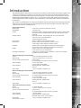
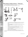
2060 Dome Camera
Installation Manual
Weatherproof and Indoor versions
www.dedicatedmicros.com
2060
Contents
Introduction............................................................ 3
RF Interference warning........................................ 4
Components supplied............................................ 5
Mounting Configurations - Indoor........................... 7
Safety Bond - Weatherproof Dome........................ 8
Safety Bond - Indoor Dome................................... 9
Ceiling Mounting - Weatherproof dome................. 10
Wall Mounting Bracket........................................... 12
Tile Mounting - Weatherproof Dome...................... 13
Dome Mounting - Weatherproof Dome.................. 15
Dome Mounting - Indoor Dome.............................. 16
Tile Mounting - Indoor Dome.................................. 17
Electrical Connections - Weatherproof Dome........ 18
Electrical Connections - Indoor.............................. 19
Control Configuration............................................. 20
Control Switches - Weatherproof Dome................ 22
Control Switches - Indoor Dome............................ 23
Switch Configuration - Indoor & Weatherproof Domes....... 24
Circuit diagram....................................................... 27
Troubleshooting..................................................... 28
Appendix A............................................................. 30
While every attempt is made to ensure these manuals are accurate and current, Dedicated Micros reserve the right to
alter or modify the specification of the machine described herein without prejudice.
Dedicated Micros ©2009
The Dedicated Micros 2060 camera is a precision unit, offering a wide variable speed range, together with
a large pre-set memory for positions, tours and alarm responses. There are sensitive day/night camera
versions with a switchable infra-red filter and with 36 times or 18 times optical zoom lenses plus 12 times
digital enhancement suitable for outdoor use, or a colour/mono camera with 18 times optical zoom and
12 times digital enhancement suitable for indoor applications. The external 2060 camera is weatherproof
(IP-66 rated).
2060
Introduction
The unit has a comprehensive set of features as standard, which can be tailored for individual preferences.
These can be accessed through an internally generated set of menus overlaid on the video signal if the
controller does not have a suitable layout.
Outline Specification:
Speed range
Repeatability
Control
Storage capacity
Power Supply
Dimensions
Protection
Weight
Mounting Configurations
0.05 to 300° / second max (both Pan and Tilt)
5 minutes of arc
RS485 half duplex or simplex, 9600 Baud Dennard, Pelco P, Bosch Ultrak
OR ‘Up the coax’ for Dedicated Micros, Dennard, BBV, Baxall or Pelco
protocols
200 preset positions, with identifying title of up to 20 characters
100 tours of up to 16 preset positions
100 alarm response memory
24VAC, Camera & control electronics:-20W
Outdoor variant: 206mm diameter x 240mm overall
Indoor variant: 189mm diameter x 250mm overall
Outdoor variant - BS EN 60529 to level IP66 (no water ingress)
Indoor variant - BS EN 60529 to level IP50 (no dust ingress)
Outdoor variant: 3kg + mounting bracket
Indoor variant: 2kg + mounting bracket
Ceiling mount, pendant mount, wall bracket, corner mount, snowdrop
parapet & tile mounts available
18X zoom day/night camera module
Sensor
Optical range
Auto-focus with manual override
Video sensitivity
Video resolution
Video output
¼” Ex-view HAD progressive scan CCD
3.4mm to 122.4mm zoom; F1.6 to F4.5
Privacy zones
24 programmable zones (8 on screen at any time)
0.07 lux color 50IRE
0.01 lux ICR-on mode 50IRE
440000 pixels PAL, 380000 NTSC
530 TVL
1.0v p-p composite, negative synch
36X zoom day/night camera module
Sensor
Optical range
Auto-focus with manual override
Video sensitivity
Video resolution
Video output
18X zoom colour/mono camera
Sensor
Optical range
Auto-focus with manual override
Video sensitivity
Video resolution
Video output
Dedicated Micros ©2009
¼” Ex-view HAD progressive scan CCD
3.4mm to 122.4mm zoom; F1.6 to F4.5
24 programmable zones (8 on screen at any time)
0.1 lux color 50IRE
0.01 lux color ICR-on 50IRE
440000 pixels PAL, 380000 NTSC
530 TVL
1.0v p-p composite, negative synch
¼” Super HAD CCD
4.1mm to 73.8mm zoom; F1.4 to F3.0
Privacy zones
24 programmable zones (8 on screen at any time)
1 lux color 50IRE
440000 pixels PAL, 380000 NTSC
More than 460 TVL PAL, 470 TVL NTSC
1.0v p-p composite, negative synch
2060
RF Interference warning
This is a class A product. In a domestic environment this product may cause radio frequency
interference, in which case the user may be required to take adequate measures.
IMPORTANT SAFETY INSTRUCTIONS
1
2
3
4
6
7
8
9
Read, follow and keep these instructions.
Heed all warnings.
Use only attachments/accessories specified by the manufacturer.
Use only with the brackets or equipment specified by the manufacturer.
Unplug this apparatus during lightening storms or when unused for long periods of time.
Refer all servicing to authorized service personnel. Servicing is required when the
apparatus has been damaged in any way, such as power cord or plug is damaged.
WARNING. DANGER OF EXPLOSION IF BATTERY IS INCORRECTLY
REPLACED. REPLACE ONLY WITH THE SAME OR EQUIVALENT TYPE.
Use a 1.5 Amp power supply provided for the weatherproof product; Use a power
supply with a minimum current of 1 amps and floating (not referenced to ground
output) for the indoor product.
CE NOTICE (EUROPEAN UNION).
Marking by the symbol CE indicates compliance of this DM product to the Electromagnetic
Compatibility Directive 89/336/EEC, and the Low Voltage Directive 73/23/EEC of the European
Union. Such marking is indicative that this system meets the following technical standards.
•
•
EN 61000-6-3 EMC Standard Residential, Commercial and Light Industry.
EN 61000-3-3 Limitations of voltage changes, fluctuations and flicker in public lowvoltage supply systems for equipment with rated current up to 16A.
•
EN 61000-3-2 Limits for harmonic current emissions for equipment with rated
current up to 16A.
•
EN 50130-4 Immunity requirements for components of fire, intruder and social
alarm systems.
•
EN 60950 Safety of IT and related equipment.
•
EN 55022 Class B. Radiated Emissions Standard, suitable for Commercial or
Residential use.
•
EN 60825-1 Safety standard for LED’s and Lasers.
Further details about these applicable standards can be obtained from Dedicated Micros LTD. 1200
Daresbury Park, Daresbury, Cheshire, WA44HS. A “Declaration of Conformity” with all relevant
European Union Directives has been made, is on file and is available from the Dedicated Micros
address above.
This product is marked with the CE symbol and indicates compliance with all applicable directives.
Directive 89/336/EEC.
Dedicated Micros ©2009
Before installing the dome, please remove the components from the packaging and verify that all
items listed below have been supplied:
2060
Components supplied
Indoor Dome
1x
Note:
Dedicated Micros 2060 Indoor Dome enclosure and camera (with incorporated
safety bond)
1x
5mm A/F hexagonal socket key
1x
Installation manual
1x
Operation and Programming Manual
The PSU must be 24VAC Power Supply with floating output and a minimum current of
1 amps. Dedicated Micros recommends the DM/94012 for indoor dome for the UK and
DM/94013 for Europe.
Note:
Mounting brackets may have been ordered and delivered separately.
Note:
Indoor domes are rated to IP50 and are not sealed against water ingress.
Weatherproof Dome
1x
Note:
Dedicated Micros 2060 IP66 Weatherproof Dome enclosure and camera (with
incorporated safety bond)
1x
Power Supply
1x
3m Flying Lead connection
1x
5mm A/F hexagonal socket key
1x
Installation manual
1x
Operation and Programming Manual
Mounting brackets may have been ordered and delivered separately.
Dedicated Micros ©2009
2060
Mounting Configurations - External
With appropriate brackets this dome enclosure can be mounted in any of the orientations shown
below. The mounting bracket is prewired for ease of installation.
Note:
Mounting brackets may have been ordered and delivered separately.
1
2
4
3
7
5
6
9
8
1.
2.
Wall/Pendant Mount (order code DM/90002) giving pendant or wall mount options.
Pendant Mount bracket (order code DM/90003) giving pendant or wall mount
options.
3.
Snowdrop mount bracket (order code DM/90004) for mounting at the top of a pole,
column or roof parapet.
4.
Vintage mount bracket (order code DM/90005) for installation near historic
buildings.
5.
Ceiling mount bracket (order code DM/90006) for solid or suspended ceilings.
6.
Tile mount (order code DM/90001) for suspended ceilings
7.
Corner bracket (order code DM/90007) for mounting to corners of buildings in
conjunction with DM/90002.
8.
Extended corner bracket (order code DM/90008) for mounting to corners of
buildings in conjunction with DM/90002.
9.
Extended wall bracket (order code DM/90009) for extending out from a wall.
All mounting versions are suitable for both weatherproof (IP66 BS EN 60529/NEMA Type 4X) and
indoor units.
Dedicated Micros ©2009
With appropriate brackets this dome enclosure can be mounted in any of the
orientations shown below. The mounting bracket is prewired for ease of installation.
Note:
2060
Mounting Configurations - Indoor
Mounting brackets may have been ordered and delivered separately.
1
2
3
1.
2.
3.
Wall/Pendant Mount (order code DM/90002) giving pendant or wall mount options.
Corner Bracket (order code DM/90007) for mounting to corners of buildings in
conjunction with DM/90002.
Tile mount (order code DM/CSD/TMR) for suspended ceilings.
Dedicated Micros ©2009
2060
Safety Bond - Weatherproof Dome
The safety bond is designed to prevent damage to the dome if it is dropped during installation or
maintenance. It should be connected between the mounting point on the dome and a suitable
secure position, either on the bracket or within the ceiling void. This point should be selected with
the consideration that it will receive the full force of the dome if it is dropped.
A
B
For wall, pendant & snowdrop/parapet mounted domes;
1.
Clip safety bond to the mounting bracket eyelet (A) on flange of bracket to secure.
For standard ceiling mounted domes attach the supplied safety bond;
Note:
1.
Attach safety bond to a suitable secure position in the ceiling void.
Always support dome with bond prior to mating connector (B). Weight of dome should be
supported by bond ensuring no stress is placed on centre connector (B) at any time.
Dedicated Micros ©2009
The safety bond is designed to prevent damage to the dome if it is dropped during installation or
maintenance. It should be connected between the mounting point on the dome and a suitable
secure position, either on the bracket or within the ceiling void. This point should be selected with
the consideration that it will receive the full force of the dome if it is dropped.
2060
Safety Bond - Indoor Dome
For wall, pendant & snowdrop mounted domes;
1.
Clip safety bond to the mounting bracket eyelet on flange of bracket to secure.
For standard ceiling mounted domes attach the supplied safety bond;
Note:
1.
Attach bond to a suitable secure position in the ceiling void.
Always support dome with bond prior to mating connector. The weight of dome should be
supported by bond ensuring no stress is placed on centre connector at any time.
Dedicated Micros ©2009
2060
Ceiling Mounting - Weatherproof dome
1.
Note:
Cut or drill a hole in the ceiling in the required position using the pattern shown
below.
The installer is responsible for ensuring the fixings used to mount the dome are suitable for
the material and will adequately support the weight of the dome.
Ø15mm
1 slot
160mm
m
113mm
2.
10
m
0m
Ø8
m
20
-1
3 x Ø15mm
113mm
160mm
Attach the mounting disc (B) to the ceiling in the chosen position and fix 4x M6x16
socket head cap screws (supplied) into the bushes (C) as shown below.
Dedicated Micros ©2009
Note:
Attach the Transfer Disc to the top of the dome enclosure using 4x prefitted M6 cap
head screws (D).
Fit the safety bond bracket (E) as shown.
2060
3.
4.
5.
Note:
Fit the safety bond between the enclosure and the mounting disk.
Offer the dome enclosure up to the ceiling mounting disk, (shown upper right)
engaging the screw heads (C) into the keyhole slots on the base of the dome (F)
enclosure. Twist once located to secure, then tighten screw heads (C) to secure the
dome enclosure to the mounting disk.
Ensure the safety bond is fitted.
Dedicated Micros ©2009
11
2060
Wall Mounting Bracket
1.
Note:
Remove the bracket base by unscrewing the outer trilobular fixings, then mark
and drill 4x Ø7mm holes using the bracket base casting as a pattern. Use a spirit
bubble level against one of the flats to align accurately.
2.
If mounting onto masonry, insert 4x M6 rawlplugs into the wall until flush.
3.
Offer the bracket base casting into position and fasten to the wall using appropriate
fixings.
Locating the dome on the corner of a building will give an increased area of surveillance.
For this application, Dedicated Micros offer an optional corner bracket, (DM90007) to adapt
the standard wall bracket.
4.
Note:
Thread the cable from the bracket throught the cable entry hole in the bottom of the
bracket casting, then fit the bracket (shown above left).
The bracket casting can be oriented to position the cable entry hole below, on either side of
at the top.
5.
12
Attach the bracket to the base using the supplied trilobular fixings (shown above
right).
Dedicated Micros ©2009
Note:
2060
Tile Mounting - Weatherproof Dome
1.
Cut or drill a hole in the tile in the required position using the pattern shown below.
The installer is responsible for ensuring the fixings used to mount the dome are suitable for
the material and will adequately support the weight of the dome.
m
5m
1
Ø2
4xØ7mm
255mm
255mm
113mm
2.
Attach the mounting disc (A) to the dome in the chosen position and use 3 of the
existing M4 dome hd screws to attach the hemisphere to the dome.
Dedicated Micros ©2009
13
2060
Note:
14
3.
Place dome, complete with attached mounting disc, into the pre-cut hole (B) in the
tile from beneath.
4.
5.
6.
From above, clamp to the tile via 2 x off split clamp rings (C).
Secure the mounting disc with 4 x supplied off M6 socket button head fixings (D).
Fit the supplied safety bond (E) to an attachment point in the ceiling.
When using soffit mount, the split clamp ring (F) must be fixed into position using 4 off M4
pan head screws (supplied)
Dedicated Micros ©2009
2060
Dome Mounting - Weatherproof Dome
1.
Note:
Secure & hang the dome to the bracket by attaching the safety bond spring clip into
the eyelet (A)
2.
Connect the central connector supplying power & control to the dome (B).
Ensure power is OFF before connecting the dome.
3.
4.
Lift the dome to the bracket flange ensuring head of screws pass through the
keyhole slots. Twist to locate and lock.
Tighten the 4 top mounting fixings with 5mm A/F Hexagonal key (as supplied) to
secure. Finally secure the plastic cover to the metal pins on the bracket flange (C).
Dedicated Micros ©2009
15
2060
Dome Mounting - Indoor Dome
1.
Note:
Secure & hang the dome to the bracket by attaching the safety bond spring clip to
eyelet (as shown).
Wall bracket shown. Procedure is the same for Snowdrop/Roof Parapet installation.
Note:
2.
Connect the central connector supplying power & control to the dome.
Ensure power is OFF before connecting the dome.
3.
4.
16
Lift the dome to bracket flange ensuring head of screws (previously fitted
M6x20mm Caphead Screw) pass through the keyhole slots. Twist to locate and
lock.
Tighten the 4 top mounting fixings with 5mm A/F Hexagonal key (as supplied) to
secure. Finally secure the plastic cover to the metal pins on the bracket flange.
Dedicated Micros ©2009
2060
Tile Mounting - Indoor Dome
Ø190mm
3 x Ø6mm
204mm PCD
A
C
D
B
E
F
1.
Note:
Remove the selected tile that will have the dome mounted to it. Use the mounting
ring (B) as a template to mark the drilling positions of the 3 x supporting holes on
a 204mm pitch circle diameter (6mmØ holes, if using the supplied cavity plugs (A))
and the 190mmØ hole for the dome. Fit the cavity plugs (A) to the holes.
The installer is responsible for ensuring the fixings used to mount the dome are suitable for
the material and will adequately support the weight of the dome.
2.
3.
Note:
Attach the mounting ring to the dome using the provided 6 x M3x8 fixings (C).
Re-install the tile in the ceiling. Secure and hang the dome to a suitable mounting
point in the ceiling void by attaching the safety bond spring clip to the eyelet
(through the large centre hole in the tile).
Ceiling installation is made easier by removing an adjacent ceiling tile during installation.
4.
Note:
Fasten the dome to the mounting ring (B) using the provided 3 x No.8x1”(25.4mm)
self tapping screws (D) (or suitable fixings provided by the installer).
5.
Snap fit the tile mount bezel (E). This replaces the standard bezel (F) provided with
the camera. Discard the standard bezel (F).
If the dome requires tile mounting Part E must be ordered separately using part number
DM/CSD/TMR.
Dedicated Micros ©2009
17
2060
Electrical Connections - Weatherproof
Dome
The Dedicated Micros 2060 external connections are via an IP66 Amphenol connector with 3 metre
composite cable flying lead that can be extended to 30 metres max., comprising co-ax, power pair &
RS485 pair. This lead should be connected to the boxed P.S.U. supplied with the dome.
A
B
a.
Multicore cable with integral Co-ax (Video)
b.
Co-ax. (Video)
The co-ax and power wires are always connected, the RS 485 wires are only connected when an
external protocol converter is fitted or an RS485 controller is being used.
18
Wire
Connection
Red
24VAC live
Blue
24VAC neutral
Yellow
RS485 A
Green
RS485 B
Coax screen
BNC screen
Coax Signal
BNC centre pin
Dedicated Micros ©2009
The dome requires connection to the power supply and to the BNC connection of the DVR. Use the
serial port connection if serial telemetry is required. There is no prepared cable included, the connector
for the camera is included.
2060
Electrical Connections - Indoor
1
9
TX+
TX-
BNC
Vid Sig
Vid GND
485B
485A
24VAC
24VAC
+
-
24V Power
Supply
Connector
24VAC
24VAC
485A
485B
Vid GND
Vid Sig
Spare Terminal
Dedicated Micros ©2009
Function
24VAC+ from 24VAC 1A
24VAC- from 24VAC 1A
Pin 1 on Serial Connection to appropriate DVR
Pin 9 on Serial Connector to appropriate DVR
BNC Earth (screen connection)
BNC Signal (centre pin connection)
Not connected
19
2060
Control Configuration
The DM 2060 Dome can be controlled by one of three methods. The configuration drawings show
the three connection arrangements. DM 2060 domes are delivered with the address switches set at
FD (DM/Dennard UTC). DM 2060 with rx domes are delivered with the address switches set at 01.
RS485
The switches on each dome must be set to a unique RS485 camera address, refer to ‘Switch
Configuration - Indoor and Weatherproof Domes ->RS485 Serial Connection’.
1 to 32 Dome Cameras
RS 485
Data Link
(Daisy chain)
connect to
controller
Local
230Va.c
input
Local
230Va.c
input
PSU
Video cable
PSU
Video cable
To Controller
RX100 or AL008 Alarm Card Configuration
The switches on all domes must be set to address 01 by setting blue switch at position 0 and yellow
switch set at position 1, refer to ‘Switch Configuration - Indoor and Weatherproof Domes’.
1 to 16 Dome Cameras
Wiring
Breakout
Box
Wiring
Breakout
Box
4 x local
alarms
drx 100
& psu
Twisted Pair
(20mA)
(current loop)
drx 100
& psu
Video cable
Video cable
4 x local
alarms
To controller
20
Dedicated Micros ©2009
The dome switches must be set according to the UTC protocol, , refer to ‘Switch Configuration
- Indoor and Weatherproof Domes’.
2060
UTC (Up the co-ax)
1 to 16 Dome Cameras
Local
230Vac
Input
PSU
Video cable
Local
230Vac
Input
PSU
Video cable
To controller
Dedicated Micros ©2009
21
2060
Control Switches - Weatherproof Dome
To access the address switches and the RS485 termination switch, remove the outer hemisphere as
shown above. The location of the switches is also shown. This operation should be carried out in an
office type environment to avoid ingress of moist air.
Note:
22
When reassembling the dome, check the hemisphere sealing gasket is in place and that the
hemisphere retaining screws are retightened to avoid water ingress.
Dedicated Micros ©2009
2060
Control Switches - Indoor Dome
To access the address switches and the RS485 termination switch, remove the outer hemisphere
by popping off the external trim and removing and retaining the three screws fastening it onto the
body. Remove and retain the four screws securing the shield to the head and lift off the shield.
The location of the switches is also shown. This operation should be carried out in an clean, dry
environment.
Dedicated Micros ©2009
23
2060
Switch Configuration - Indoor and
Weatherproof Domes
The same address switches are used for both RS485 and up the coax control.
Up the Coax Configuration
Switch settings
The switches are color coded, blue and yellow, and are located inside the dome camera housing.
Configure the switches for the controller being used as shown in table below.
Note:
The switches are factory set to FD (DM up the coax control).
Up the Coax Switch Configuration
Control
Blue Yellow
DM/Dennard up the coax
F
D
Pelco Coaxitron up the coax
F
8
Baxall AC controllers
F
C
Baxall DC controllers
F
E
For up the coax control using external protocol convertors or alarm interfaces such as RX100 or
AL008, the address switches should be set to Blue - 0 Yellow - 1.
RS485 Serial Connection
The coax cable and power wires are always connected.
The RS485 wires are only connected when an RS485 controller is being used.
The dome supports a range of serial RS485 PTZ protocols. The desired protocol and the node
address for the dome are selected by the two rotary hex switches (blue and yellow) inside the
dome. These are accessed by removing the outer hemisphere and inner shroud, refer to Switch
Configuration for more information.
The switch settings for the protocols and node addresses are shown in the table below.
To use the table;
1.
Select the protocol required
2.
Select the node address of the dome to be configured.
3.
Scan across the table to identify the values for the blue and yellow switches.
For example, if the dome is to be used with a Dedicated Micros PTZ controller system with address
ID#5 the switches should be set to ‘05’. i.e. the blue switch should be set to ‘0’ and the yellow switch
set to ‘5’.
24
Dedicated Micros ©2009
2060
The dome will display its switch setting when first powered on as the screen will show (in the
example above) “CAM 05”.
Set the individual RS485 address for the dome on the blue and yellow switches fitted inside the
dome housing.
Set each switch to its desired position as shown in the table.
Extended RS485 addressing
The dome can be configured to allow up to 239 Dennard or Pelco P RS485 addresses to be used.
The mechanism needs to be removed from the dome to enable this.
1.
2.
3.
Follow the instructions to access the address switches, then unscrew 4x posi
screws that hold the mechanism mounting in place and unclip the connector from
the rear.
Locate SW3 on the main PCB adjacent to the mounted connector attaching the
daughter board housing the yellow and blue address switches.
Set SW3 using the following parameters
Protocol
SW3
1
2
3
4
5
6
7
8
Extended Dennard RS485 on
off
off
off
off
off
off
off
Extended Pelco RS485
off
on
off
off
off
off
off
off
Multi-protocol (default)
off
off
off
off
off
off
off
off
Dedicated Micros ©2009
25
2060
Termination
All Dedicated Micros 2060 domes are fitted with a termination switch, shown above. If a single dome
is connected on the RS485 line, or if a star configuration is used, the termination switch should be
switched to ‘IN’ (towards the colored address switches).
If multiple domes are connected in a ‘daisy chain’ configuration, then only the last dome in the chain
should be switched to ‘IN’. All other domes in the chain should be switched to “OUT’.
Note:
26
If the dome is being used with Dedicated Micros latest DVIP products (DV-IP
Express, DV-IP Server, DV-IP HD, DV-IP RT), the termination should be switched
to ‘OUT’ in all circumstances.
Dedicated Micros ©2009
2060
Circuit diagram
drx options
500mA
FUSE
L
240V AC E
I/P
N
240V
0V
RD
24Vac
2A5
BK
GN/YL
BL
2Amp
FUSE
RD
BR
WH/RD
WH/BK
POWER FROM
DOME
BL
250mA
FUSE
WH/RD
9V
100mA WH/BK
9Vac 100mA
TO drx100 CARD
FITTED CALL SEQUENCES
LINK J6/4-5 LOCAL ALARM HANDLING REMOVED CALL PRESET POSITIONS
LINK J6/1-2 STARTS SEQUENCE 1 AFTER 10 MINS INACTIVITY
J6
J4
9-12V
SUPPLY
or
TWISTED
PAIR 1/P
RS485
FROM DOME
GN
YL
ALARM O/P
ALARM I/P’s 4 OFF
J3
VIDEO IN FROM DOME
U2
AC
AC
TP
TP
GND
C1
C2
C3
C4
GND
A OUT
A OUT
GND
GND
A1
A2
A3
A4
VIDEO OUT TO TRANSMITTER
J1
LIGHTS
SUPPLY IN
& DOME O/P
J5
drx100 PCB ASSY.
RS485/Up the Co-ax Configuration
COAX TO
CONTROLLER
COMPOSITE CABLE
FROM DOME
0V
240V
DRAIN
WIRE NOT
CONNECTED
RD
POWER TO
DOME
FS2 2A
L
RD
BR
E
N
BL
RS485 A
RS485 B
TO DOME
Dedicated Micros ©2009
24Vac
2A5
0V
24V
N/U
COAX FROM
DOME
YL
GR
L
E
BK
BL
N
FS1 500mA
240V AC
I/P
MAINS IN
CONNECT FOR
RS485 CONTROL ONLY
DO NOT CONNECT
FOR UP THE CO-AX CONTROL
27
2060
Troubleshooting
No Picture
Cause
1.
Check the Input and Output voltage
2.
Check the continuity on the power and video cables.
3.
Check the multicore cable on the weatherproof dome;
Pin
Signal
1
Video
2
Video screen
3
Data + (yellow)
4
Data - (green)
5
24V neutral (blue)
6
24V live (red)
E
Earth (drain wire)
No Control
1.
Check the DVR is set to use the correct telemetry protocol and address settings.
2.
Check the dome address switches are correctly set for the controller being used.
3.
If RS485 telemetry is being used, check that the cable is connected to the serial port
configured in the menus of the DVR, and that the RS485 connections are the correct way around
(yellow=Data+ & green=Data-).
Picture with intermittent control
Cause
1.
2.
Control up the coax - This is most likely due to too much or too little video gain.
Dome in co-ax mode requires video level be set to 1V p-p.
i.
Open the Technician menu (see Operation and Programming
manual for details on accessing the menu).
ii.
Select ‘Miscellaneous Services’
iii.
Select ‘Host Comms/Video Amp’.
iv.
Adjust lift and gain settings.
RS485: Termination may be incorrect - check termination switch settings, refer to
‘Switch Configuration - Indoor and Weatherproof Domes’ ->’Termination’.
Dome spins continuously (DM controllers)
Cause
No joystick dead band recognized as joystick was off centre during powerup.
Solution
Reboot the controller with the joystick self centred.
Reset the Dome (software reset)
1.
2.
28
Open the Technician Menu (see Operation and Programming manual for details on
accessing the menu).
Select ‘Miscellaneous Services’
Dedicated Micros ©2009
2060
Note:
3.
Select ‘NVM Services’.
4.
Select ‘Reload Factory defaults’.
This will delete all preset positions and tours from the dome memory.
Software Version
To check the version of software installed in the dome;
1.
Open the Technician Menu (refer to the Operation and Programming manual for
details on accessing the menus).
2.
Select ‘Maintenance Services’.
3.
Select ‘Software Version’.
The OSD will display the version of software installed in the dome.
Camera Version
To verify the version of camera supported by the dome software;
1.
Open the Technician Menu (see Operation and Programming manual for details on
accessing the menu).
2.
Select ‘Miscellaneous Services’
3.
Select ‘Reset Head’.
As the dome resets, the OSD will display a reference number similar in format to
“1.4 V MB42”
The single letter in the middle of the reference indicates the supported camera, refer to the table
below for more information.
Letter
N
O
V
M
X
Y
Dedicated Micros ©2009
Camera Model
36x Day/Night
36x Day/Night
18x Colour/Mono
18x Colour/Mono
18x Day/Night
18x Day/Night
Resolution
530TVL
530TVL
460TVL
470TVL
530TVL
530TVL
Format
PAL
NTSC
PAL
NTSC
PAL
NTSC
29
2060
Appendix A
DM 2060 Fixed Attitude Dome Camera - Setup
Telemetry cameras can be positioned remotely, fixed atitude cameras require manual adjustment to
position the camera. Framing the desired camera image will be easier using a local monitor.
To Frame the image from a Fixed attitude camera;
1.
Unscrew the 6x fixings securing the outer hemisphere to the casing and remove.
2.
Note:
Grip the inner hemisphere and rotate to adjust the Pan position of the camera. This
adjustment povides up to 180˚ of pan right and pan left movement.
Do not rotate more than 180˚ in either direction as this will stress the connections to
the camera.
3.
Grip the camera platform, accessible through the camera viewing slot, to adjust the tilt
position. This provides tilt up/down adjustment, refer to ‘Zoom Cam Setup’ for more information.
30
Dedicated Micros ©2009
The Dedicated Micros 2060 Fixed Attitude Camera Dome is supplied with an IP66 Amphenol
connector with 3 metre composite cable flying lead. The connector mates with the dome as shown in
the image below.
2060
DM 2060 Fixed Attitude Dome Camera - Electrical Connections
A
B
a.
Multicore cable with integral Co-ax (Video)
b.
Co-ax. (Video)
The co-ax and power wires are always connected, the RS 485 wires are only connected when an
external protocol converter is fitted or an RS485 controller is being used.
Wire
Connection
Red
24VAC live
Blue
24VAC neutral
Yellow
RS485 A
Green
RS485 B
Coax screen
BNC screen
Coax Signal
BNC centre pin
}
Not required for
fixed attitude dome
VIDEO TO
MONITOR
VIDEO FROM
DOME
FS2 500mA
230Vac I/P
MAINS
IN
L
BN
E
N
Dedicated Micros ©2009
230V
24V
RD
0V
BL
0V
10V
0V
BK
FS1 2A
24Vac
L
E
N
HEATER
SUPPLY
24Va.c.
31
2060
DM 2060 Fixed Attitude Dome Camera - ‘Zoom Cam’ Setup
The DM 2060 Fixed Attitude ‘Zoom Cam‘ is equipped wih the ‘zoom cam’ high resolution camera.
This offers a range of features which are described below.
1.
Note:
Control
Remote zoom control requires a Dennard, BBV or DM telemetry controller and the
removal of lnk ‘B’ (refer to ‘View of right side of camera’ below and to point 6).
2.
Presets
The ‘zoom cam’ can store up to 8 user definable zoom presets within memory, refer
to the relevant controller instructions for preset programming details.
3.
Default Position
After a definable period of inactivity (default setting 1 minute) the ‘zoom cam’ will
default to preset 1 (or wide angle if no presets are configured). On DM and BBV
controllers, the setting ‘Patrol 2 delay program‘ will adjust the time interval. Intervals
steps are 1, 2, 3, 4, 5, 6, 8 & 10 minutes, using co-responding keys 1-8.
4.
Patrol
The ‘zoom cam’ patrol feature can be used to sequence between the preset
positions. Follow the relevant controller instructions to setup ‘Patrol 1’. Patrol mode
is cancelled with any manual zoom action.
5.
Video level adjustment
Video level is factory set, but can be adjusted by turning VR1, located just above
link ‘B’ on the receiver board (refer to ‘View of right side of camera’ below). This will
lighten/darken the picture to compensate for the length of co-ax required.
6.
Fixed lens
When no remote control is available, the zoom cam can function as a fixed lens
camera.
a.
Ensure link ‘B‘ is fitted as shown (refer to ‘View of right side of camera’
below) between pins 9&10 on power up.
b.
Frame the preset picure required by zooming, using the buttons (A) on
the left side of the camera (refer to ‘View of left side of camera’ below).
c.
Remove the link ‘B’ for ten seconds and then refit. The link must be left
on permanently.
To revert to ‘zoom cam’ operation, the link must be removed and power to the camera
cycled (removed and reapplied).
View of left side of camera
32
View of right side of camera
Dedicated Micros ©2009
Dedicated Micros ©2009
2060
Notes
33
2060
34
Notes
Dedicated Micros ©2009
Appendix A................................................................................................................................................... 30
Camera Version............................................................................................................................................ 29
Ceiling Mounting - Weatherproof dome........................................................................................................ 10
CE NOTICE (EUROPEAN UNION)................................................................................................................ 4
Circuit diagram............................................................................................................................................. 27
2060
Index
Components supplied..................................................................................................................................... 5
Contents......................................................................................................................................................... 2
Control Configuration................................................................................................................................... 20
Control Switches - Indoor Dome.................................................................................................................. 23
Control Switches - Weatherproof Dome....................................................................................................... 22
DM 2060 Fixed Attitude Dome Camera - ‘Zoom Cam’ Setup....................................................................... 32
DM 2060 Fixed Attitude Dome Camera - Electrical Connections................................................................. 31
DM 2060 Fixed Attitude Dome Camera - Setup........................................................................................... 30
Dome Mounting - Indoor Dome.................................................................................................................... 16
Dome Mounting - Weatherproof Dome......................................................................................................... 15
Dome spins continuously (DM controllers)................................................................................................... 28
drx options.................................................................................................................................................... 27
Electrical Connections - Indoor.................................................................................................................... 19
Electrical Connections - Weatherproof Dome.............................................................................................. 18
Extended RS485 addressing........................................................................................................................ 25
For standard ceiling mounted domes attach the supplied safety bond;......................................................... 8
For standard ceiling mounted domes attach the supplied safety bond;......................................................... 9
For wall, pendant & snowdrop/parapet mounted domes;............................................................................... 8
For wall, pendant & snowdrop mounted domes;............................................................................................ 9
IMPORTANT SAFETY INSTRUCTIONS........................................................................................................ 4
Indoor Dome................................................................................................................................................... 5
Introduction..................................................................................................................................................... 3
Mounting Configurations - Indoor................................................................................................................... 7
No Control.................................................................................................................................................... 28
No Picture..................................................................................................................................................... 28
Outline Specification: . ................................................................................................................................... 3
Picture with intermittent control.................................................................................................................... 28
Reset the Dome (software reset)................................................................................................................. 28
RF Interference warning................................................................................................................................. 4
RS485.......................................................................................................................................................... 20
RS485/Up the Co-ax Configuration.............................................................................................................. 27
RS485 Serial Connection............................................................................................................................. 24
Safety Bond - Indoor Dome............................................................................................................................ 9
Safety Bond - Weatherproof Dome................................................................................................................ 8
Software Version.......................................................................................................................................... 29
Switch Configuration - Indoor and Weatherproof Domes............................................................................. 24
Termination................................................................................................................................................... 26
Tile Mounting - Indoor Dome........................................................................................................................ 17
Tile Mounting - Weatherproof Dome............................................................................................................ 13
To Frame the image from a Fixed attitude camera;...................................................................................... 30
To use the table;........................................................................................................................................... 24
Troubleshooting............................................................................................................................................ 28
Twisted Pair Configuration........................................................................................................................... 20
Up the Coax Configuration........................................................................................................................... 24
Up the Coax Switch Configuration............................................................................................................... 24
UTC (Up the co-ax)...................................................................................................................................... 21
Wall Mounting Bracket.................................................................................................................................. 12
Weatherproof Dome....................................................................................................................................... 5
Dedicated Micros ©2009
35
Dedicated Micros Ltd.
1200 Daresbury Park, Daresbury,
Cheshire, WA4 4HS, UK
Dedicated Micros USA.
14434 Albemarle Point Place, Suite 100,
Chantilly, Virginia 20151 USA
Dedicated Micros Benelux
Joseph Chantraineplantsoen 1,
3070 Kortenberg, Belgium
Dedicated Micros Europe
Hamtorstraße 9,
41460 Neuss, Germany
Dedicated Micros, Australia PTY.
5/3 Packard Avenue, Castle Hill,
NSW 2154, Australia
Dedicated Micros France
9-13 rue du Moulinet
75013 Paris, France
Dedicated Micros, Asia PTY
16 New Industrial Road,
#03-03 Hudson Techno Centre,
Singapore 536204
Dedicated Micros Slovenia
Delavska cesta 26,
4208 Sencure, Slovenia
Dedicated Micros Middle East
Building 12, Suite 302, P.O. Box 500291, Dubai Internet
City, Dubai, United Arab Emirates
Dedicated Micros (Malta) Ltd.
BLB017, Bulebel Industrial Estate,
Zejtun, ZTN08, Malta
Installed by
UK:MI-I-2060/E1-0
Dennard Ref: 740417 Rev 1