1
StorageWorks Secure Path
for Windows NT
A High Availability Solution
Installation Guide
EK–WNTMP–MH. D01
Compaq Computer Corporation
123995–002
While Compaq Computer Corporation believes the information included in this manual is correct
as of the date of publication, it is subject to change without notice. Compaq makes no
representations that the interconnection of its products in the manner described in this document
will not infringe existing or future patent rights, nor do the descriptions contained in this
document imply the granting of licenses to make, use, or sell equipment or software in
accordance with the description. No responsibility is assumed for the use or reliability of
firmware on equipment not supplied by Compaq or its affiliated companies. Possession, use, or
copying of the software or firmware described in this documentation is authorized only pursuant
to a valid written license from Compaq, an authorized sublicensor, or the identified licensor.
Commercial Computer Software, Computer Software Documentation and Technical Data for
Commercial Items are licensed to the U.S. Government with Compaq’s standard commercial
license and, when applicable, the rights in DFAR 252.227 7015, “Technical Data Commercial
Items.”
© 1999 Compaq Computer Corporation.
All rights reserved. Printed in U.S.A.
Compaq, DIGITAL, Tru64 UNIX, DECconnect, HSZ, HSG StorageWorks, VMS, OpenVMS, and
the Compaq logo are trademarks of Compaq Computer Corporation.
UNIX is a registered trademark in the United States and other countries exclusively through
X/Open Company Ltd. Windows NT is a trademark of the Microsoft Corporation. Sun is a
registered trademark of Sun Microsystems, Inc. Hewlett-Packard and HP-UX are registered
trademarks of the Hewlett-Packard Company. IBM and AIX are registered trademarks of
International Business Machines Corporation. SGI and IRIX are trademarks of Silicon Graphics,
Incorporated. All other trademarks and registered trademarks are the property of their respective
owners.
This equipment has been tested and found to comply with the limits for a Class A digital device,
pursuant to Part 15 of the FCC Rules. These limits are designed to provide reasonable protection
against harmful interference when the equipment is operated in a commercial environment. This
equipment generates, uses and can radiate radio frequency energy and, if not installed and used in
accordance with the manuals, may cause harmful interference to radio communications.
Operation of this equipment in a residential area is likely to cause harmful interference in which
case the user will be required to correct the interference at his own expense. Restrictions apply to
the use of the local-connection port on this series of controllers; failure to observe these
restrictions may result in harmful interference. Always disconnect this port as soon as possible
after completing the setup operation. Any changes or modifications made to this equipment may
void the user's authority to operate the equipment.
Warning!
This is a Class A product. In a domestic environment this product may cause radio interference in
which case the user may be required to take adequate measures.
Achtung!
Dieses ist ein Gerät der Funkstörgrenzwertklasse A. In Wohnbereichen können bei Betrieb dieses
Gerätes Rundfunkstörungen auftreten, in welchen Fällen der Benutzer für entsprechende
Gegenmaßnahmen verantwortlich ist.
Avertissement!
Cet appareil est un appareil de Classe A. Dans un environnement résidentiel cet appareil peut
provoquer des brouillages radioélectriques. Dans ce cas, il peut être demandé à l’ utilisateur de
prendre les mesures appropriées.
JAPAN
USA
This equipment generates, uses, and may emit radio frequency energy. The equipment has been
type tested and found to comply with the limits for a Class A digital device pursuant to Part 15 of
FCC rules, which are designed to provide reasonable protection against such radio frequency
interference. Operation of this equipment in a residential area may cause interference in which
case the user at his own expense will be required to take whatever measures may be required to
correct the interference. Any modifications to this device - unless expressly approved by the
manufacturer - can void the user’s authority to operate this equipment under part 15 of the FCC
rules.
Contents
Revision Record
About This Guide
Audience ...........................................................................................................................................................xi
Document Structure .........................................................................................................................................xi
Conventions................................................................................................................................................... xiii
Support and Services .................................................................................................................................... xiii
COMPAQ StorageWorks Web Site Address ............................................................................................. xiii
1
2
3
Theory of Operation
1.1
An Overview of Secure Path for Windows NT................................................................................1–1
1.2
Secure Path Technology.....................................................................................................................1–2
1.3
Implementation ...................................................................................................................................1–2
1.4
Installation and Configuration ...........................................................................................................1–3
1.5
The Secure Path Software for Microsoft Windows NT...................................................................1–5
Choosing a Method of Installation
2.1
Quick Setup Method ...........................................................................................................................2–1
2.2
Comprehensive RoadMap Method....................................................................................................2–1
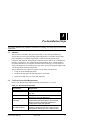
Pre-Installation Steps
3.1
Summary..............................................................................................................................................3–1
3.2
Verify the Secure Path Requirements ...............................................................................................3–1
3.3
Inventory the StorageWorks Kits Required for Secure Path ..........................................................3–2
3.4
Examine the Current Configuration ..................................................................................................3–4
3.5 Prepare the RAID Array for Secure Path Operation........................................................................3–4
3.5.1
Preparing an Existing RAID Array for Secure Path Operation................................................3–5
3.5.2
Preparing a New RAID Array for Secure Path Operation........................................................3–5
EK–WNTMP–MH. D01
123995–002
v
StorageWorks Secure Path for Windows NT
4
Installing Secure Path Software
4.1
Summary .............................................................................................................................................4–1
4.2 Installing the Secure Path Software ..................................................................................................4–1
4.2.1
Description of the Secure Path Software ...................................................................................4–1
4.2.2
Installing the Secure Path Driver and Agent .............................................................................4–2
4.2.3
Installing the Secure Path Manager ............................................................................................4–2
4.3
Establishing a Serial Link to the RAID Subsystem .........................................................................4–3
4.4 Configuring the RAID Subsystem for Secure Path Operation .......................................................4–3
4.4.1
Setting HSZ70 or HSG80 Controllers to Multiple-Bus Failover Mode ..................................4–3
4.4.2
“Preferring” Storage Unit Paths..................................................................................................4–4
5
Installing Secure Path Hardware
5.1
Summary..............................................................................................................................................5–1
5.2 Prepare and Install the Second SCSI Host Adapter ........................................................................5–1
5.2.1
Setting Up SCSI Host Adapters ..................................................................................................5–2
5.3 Installing Cables and Termination ....................................................................................................5–2
5.3.1
Installing an RA7000 or ESA10000 (SCSI) with One Windows NT Server..........................5–3
5.3.2
Installing an RA7000 or ESA10000 (SCSI) with a Windows NT Clusters with Y-Cables...5–4
5.3.3
Installing an RA7000 or ESA10000 (SCSI) with a Windows NT Cluster with SCSI Hubs .5–5
5.3.4
Installing an RA8000 or ESA12000 (Fibre Channel) with One Windows NT Server...........5–6
5.3.5
Installing an RA8000 or ESA12000 (Fibre Channel) with a Windows NT Cluster...............5–7
5.4
6
Verify the Secure Path Hardware Configuration .............................................................................5–7
Using Secure Path Manager
6.1 About Secure Path Manager ................................................................................................................6–1
6.2 Secure Path Manager Login and Agent Connection..........................................................................6–2
6.3 Host Connection Status Montior .........................................................................................................6–4
6.4
6.5
6.6
Path and Drive Status Monitor ..........................................................................................................6–5
Assigning New Primary Paths to Drives ..........................................................................................6–6
Balancing the I/O Load Between Paths ............................................................................................6–7
6.7
Defining a Persistent Secure Path RAID Array Drive Configuration ............................................6–7
6.8 Automatic Failover .............................................................................................................................6–8
6.8.1
Automatic Failover Detection and Status Reporting ................................................................6–8
6.9
Automatic Failback.......................................................................................................................... 6–10
6.10 Manual Failback and Status Reporting .......................................................................................... 6–11
6.11 Notification when No-Single-Point-of-Failure is Compromised ................................................ 6–12
6.11.1 No Preferred Path Detectable upon Server Boot .................................................................... 6–13
6.11.2 No Redundant Path Detectable upon Server Boot ................................................................. 6–14
6.12 Adding New Storagesets with Secure Path.................................................................................... 6–15
6.13 Removing a Storageset with Secure Path ...................................................................................... 6–15
vi
123995–002
EK–WNTMP–MH. D01
Contents
Appendix A
Quick Setup
RA7000 or ESA10000 (SCSI) and One Windows NT Server.................................................................A–2
RA7000 or ESA10000 (SCSI) and a Windows NT Cluster with SCSI Y-Cables..................................A–5
RA7000 or ESA10000 (SCSI) and a Windows NT Cluster with SCSI Hubs.........................................A–8
RA8000 or ESA12000 (Fibre Channel) and One Windows NT Server................................................A–11
RA8000 or ESA12000 (Fibre Channel) and a Microsoft Windows NT Cluster..................................A–13
Appendix B
De-Installing Secure Path Software
Appendix C
Troubleshooting Secure Path Connection Problems
Figures
1–1 Secure Path Single Host Configuration ............................................................................................1–4
1–2 Secure Path Microsoft Cluster Configuration ..................................................................................1–4
5–1 Secure Path Hardware Interconnect – SCSI Single Server .............................................................5–3
5–2 Secure Path Hardware Interconnect – SCSI Cluster Y-Cable ........................................................5–4
5–3 Secure Path Hardware Interconnect –SCSI Cluster Hub.................................................................5–5
5–4 Secure Path Hardware Interconnect – Fibre Channel Single Server ..............................................5–6
5–5 Secure Path Hardware Interconnect – Fibre Channel Cluster.........................................................5–7
6–1 Invoking the Secure Path Manager ...................................................................................................6–2
6–2 Secure Path Login Window ...............................................................................................................6–2
6–3 Stopping the Secure Path Agent ........................................................................................................6–3
6–4 Secure Path Host Connection Icons ..................................................................................................6–4
6–5 Typical Secure Path Manager Display..............................................................................................6–5
6–6 Automatic Disk Failover from Failed Path Controller A ................................................................6–9
6–7 Enabling the Auto-Failback Feature .............................................................................................. 6–10
6–8 Secure Path Indicates when Preferred Path is Undetectable ........................................................ 6–13
6–9 Secure Path Indicates when Redundant Path is Undetectable ..................................................... 6–14
Tables
3–1 Secure Path Prerequisites ...................................................................................................................3–1
EK–WNTMP–MH. D01
123995–002
vii
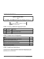
Revision Record
This Revision Record provides a concise publication history of this manual. It lists the manual
revision levels, release dates, and reasons for the revisions.
The following revision history lists all revisions of this publication and their effective
dates. The publication part number is included in the Revision Level column, with the last
entry denoting the latest revision.
Revision Level
Date
Summary of Changes
EK–WNTMP–MH. A01
June 1998
Original release. Secure Path Software V1.0
Single Host – SCSI RA7000 / ESA10000
EK–WNTMP–MH. B01
November 1998
Secure Path Software V2.0
Supports Fibre Channel RA8000 / ESA12000
RAID Arrays and Microsoft Cluster Server
EK–WNTMP–MH. C01
March 1999
Secure Path Software V2.1
Supports automatic path failback
Provides StorageWorks Data Replication
Management (DRM) to support disaster
tolerant HSG80 configurations
Includes minor Secure Path Manager
enhancements
EK–WNTMP–MH. D01
May 1999
Secure Path Software V2.2
Notification of Undetectable Preferred or
Reundant Paths upon Server Boot
EK-WNTMP-MH. D01
123995–002
ix
About This Guide
This section defines the scope, structure and conventions of this guide. It identifies associated
reference documentation, and the StorageWorks sales, service, and technical support contacts
worldwide.
Audience
This guide is intended for administrators and system integrators of Intel or Alpha based
host servers and StorageWorks RAID storage solutions. Setting up a Secure Path
environment requires a general understanding of server networks, RAID storage concepts
and device drivers, Windows NT software, SCSI and/or Fibre Channel hardware
configurations. Or, contact your service representative for installation assistance.
Document Structure
This guide contains the following chapters:
Chapter 1: Theory of Operation
This chapter offers an overview of Secure Path for Windows NT, and explains the
operation of Secure Path in a No-Single-Point-of-Failure configuration.
Chapter 2: Choosing an Installation Method
This chapter describes the two methods, available in this guide, to install and configure
Secure Path for Windows NT.
Chapter 3: Pre-Installation Steps
This chapter addresses the preparation needed before installing and configuring the
Secure Path components.
Chapter 4: Installing Secure Path Software
This chapter describes the software configuration procedures required to establish a
Secure Path storage environment. It includes the procedures to set the two StorageWorks
RAID controllers for multiple-bus mode operation, prefer storagesets between the
controllers, and install the StorageWorks Secure Path software on the host servers and
client.
EK–WNTMP–MH. D01
123995–002
xi
StorageWorks Secure Path for Windows NT
Chapter 5: Installing Secure Path Hardware
This chapter provides the procedures for preparing the host bus adapters, and
interconnecting Secure Path hardware components.
Chapter 6: Using Secure Path Manager
This chapter describes features of the Secure Path Manager. The Secure Path storage
environment can be monitored and managed using the Secure Path Manager. Secure Path
Manager provides graphic representation of bus path vitality status, disk I/O path
assignments, automatic path failover, automatic path failback, and manual path failback
functionality.
Appendix A: Quick Setup
This section provides simplified installation instructions to enable experienced system
integrators and administrators to quickly establish a Secure Path environment.
Appendix B: De-Installing Secure Path Software
The procedure for removing Secure Path software from your system is provided in this
appendix.
Appendix C: Troubleshooting Secure Path Connection Problems
This appendix describes general network configuration issues which might affect the
ability of the Secure Path Client and Agent to establish connection.
xii
123995–002
EK–WNTMP–MH. D01
About This Guide
Conventions
In this guide, references to RAID, Array, subsystem, HSZ70, RA7000, ESA10000; HSG80,
RA8000 or ESA12000 pertain to either of the following:
• UltraSCSI Raid Array 7000 or Enterprise Storage Array (ESA) 10000
• Fibre Channel Raid Array 8000 or Enterprise Storage Array (ESA) 12000
This guide uses the following documentation conventions:
Style Conventions
Style
Meaning
boldface monospace type
italic type
plain monospace type
To be input by the user.
For emphasis, manual titles, utilities, menus, screens,
and filenames.
Screen text.
HS*** >
RAID controller prompt
Getting Help
If you have a problem and have exhausted the information in this guide, you can get
further information and other help in the following locations.
Compaq Web Site
The Compaq Web Site has information on this product as well as the latest drivers and
Flash ROM images. You can access the Compaq Web Site by logging on to the Internet
at:
http://www.compaq.com
Telephone Numbers
For the name of your nearest Compaq Authorized Reseller:
In the United States, call 1-800-345-1518
In Canada, call 1-800-263-5868
For Compaq technical support:
In the United States and Canada, call 1-800-386-2172
EK–WNTMP–MH. D01
123995–002
xiii
1
Theory of Operation
This section provides an overview of StorageWorks Secure Path v2.2 for Windows NT.
1.1
An Overview of Secure Path for Windows NT
StorageWorks Secure Path is a high availability software product providing continuous
data access for Ultra SCSI RAID Array 7000 / Enterprise Storage Array 10000 and Fibre
Channel RAID Array 8000 / Enterprise Storage Array 12000 storage subsystems
configured on Windows NT 4.0 Intel or Alpha platforms. Redundant hardware, advanced
RAID technology and automated failover capability are used to enhance fault tolerance
and availability. Secure Path, in conjunction with your StorageWorks RAID Array
subsystem, effectively eliminates controllers, disk drives, interconnect hardware and host
bus adapters as single points of failure in the storage subsystem.
Secure Path v2.2 allows a StorageWorks dual-controller RAID subsystem to be cabled on
two independent SCSI busses or Fibre Channel loops, using two separate host bus
adapters in each server.
Secure Path monitors each path and automatically re-routes I/O to the functioning,
alternate path should an adapter, cable, hub or controller failure occur. Failure detection is
reliable and designed to prevent false or unnecessary failovers. Failovers are transparent
and non-disruptive to applications.
The Secure Path management utility provides continuous monitoring capability and
identifies failed paths and failed-over storage units. To facilitate static load balancing,
devices can be moved between paths using simple “drag-and-drop” operations.
Through the use of dual RAID controllers configured in an active/active multiple-bus
mode of operation, Secure Path can also exploit the potential for improved data
throughput and bandwidth performance.
EK–WNTMP–MH. D01
123995–002
1–1
StorageWorks Secure Path for Windows NT
1.2
Secure Path Technology
Key to Secure Path’s functionality is the capability of dual StorageWorks RAID
controllers to operate in an active/active implementation referred to as dual-redundant
multiple-bus mode. Multiple-bus mode allows each controller to be configured on its own
bus and to process I/O independently under normal operation. Available storage units are
preferred to one or the other of the two controllers by setting a PREFERRED_PATH unit
attribute. This attribute determines which controller path is used for access at system boot
time. During runtime, units may be moved between paths at any time through use of the
Secure Path Management utility.
The Secure Path software detects the failure of I/O operations on a failed controller’s path
and automatically re-routes all traffic to the path of the surviving controller. Controller
and path failover is completed seamlessly, without process disruption or data loss.
Secure Path version 2.2 provides auto-failback capability. With auto-failback enabled,
Secure Path will monitor a failed path and automatically return failed-over storage units
to their original path, once the path has been restored. Anti-thrash filters are implemented
to prevent ping-pong effects resulting from marginal or intermittent conditions. The user
may select auto or manual failback policy through use of the Secure Path Management
utility.
Following a warm-swap of a failed controller, adapter or cable component, storage units
can be failed-back to their original path using the Secure Path Management utility.
To protect against drive failure in a Secure Path environment, storage units can be
configured using raid levels 0+1, 1, 3/5, or 5. Secure Path will support either FAT or
NTFS file system formats on single host configurations. Microsoft requires the NTFS file
system in Microsoft Cluster Server (MSCS) configurations.
1.3
Implementation
Secure Path’s primary failover capability is implemented in a Windows NT filter driver
called RaiDisk. RaiDisk provides support for the StorageWorks RAID subsystem
multiple-bus mode of operation and provides all functions required for monitoring I/O and
detecting path failures.
1-2
123995-002
EK-WNTMP-MH. D01
Chapter 1. Theory of Operation
Secure Path also incorporates the custom Windows NT class driver, HszDisk, developed
for use with StorageWorks RAID Array controllers. This class driver provides unique
error handling features and performance enhancements not available in the native
Windows NT disk class driver.
Multiple-bus management is implemented using Secure Path Manager. Secure Path
Manager is a client/server graphical application that continuously monitors the multiplebus storage environment and automatically updates the displayed configuration
information. Secure Path Manager indicates which path is currently servicing each
configured storage unit. Online, offline, and pending state information for available
storage units and paths is depicted using color codes. The capability to swap storage units
between paths is also provided through simple “drag-and-drop” operations.
1.4
Installation and Configuration
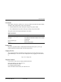
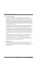
A single host Secure Path configuration is comprised of a server, two host bus adapters, a
StorageWorks RAID Array subsystem, and two sets of cables. A Secure Path single
server configuration is shown in Figure 1-1.
A Microsoft Cluster Secure Path configuration is comprised of two servers, two host bus
adapters in each server, a StorageWorks RAID Array subsystem, and two sets of cables.
A Secure Path Microsoft Cluster configuration is shown in Figure 1-2.
All Secure Path software components are installed on either Intel or Alpha based
platforms using the same InstallShield based setup utility. The setup procedure requires
that a standard single path configuration be established, with all storage units defined,
prior to installation of the Secure Path software. The Secure Path software is then
installed on the single path configuration before re-configuration of the storage controllers
for multiple-bus mode and installation of hardware for the redundant path. This softwarefirst/hardware-second procedure allows the operating system to properly configure the
multiple-bus environment when rebooted.
For previously installed subsystems, no modifications are required to existing storage
units or data volumes.
EK-WNTMP-MH. D01
123995-002
1-3
StorageWorks Secure Path for Windows NT
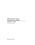
Figure 1–1 Secure Path Single Host Configuration
Figure 1–2 Secure Path Microsoft Cluster Configuration
Network Interconnect
WNT
Server
HBA
HBA
Clients
RAID
Subsystem
WNT
Server
HBA
HBA
Controller A
Controller B
SHR-1274-99EPS
1-4
123995-002
EK-WNTMP-MH. D01
Chapter 1. Theory of Operation
1.5
The Secure Path Software for Microsoft Windows NT
The Secure Path (v2.2) Software Kit for Microsoft Windows NT is comprised of the
following software components:
•
HszDisk.sys is a Windows NT class driver that works with StorageWorks RAID
Array controllers to enhance on-line storage availability and fault-tolerance. HszDisk
works in single-host and cluster environments to maintain optimum subsystem
performance during controller and storageset error recovery operations.
•
RaiDisk.sys is a Windows NT filter driver that provides support for multiple-bus
mode operation with StorageWorks RAID Arrays. RaiDisk performs automatic
failover of storagesets to the alternate path in the event of a primary path failure.
•
Secure Path Manager is the client application used to manage multiple-bus
StorageWorks RAID Array configurations. Secure Path Manager displays a graphical
representation of the current multiple-bus environment and indicates the location and
state of all configured storagesets on each of the paths. To facilitate static load
balancing, Secure Path Manager provides the capability to move storagesets between
paths. Secure Path Manager can be run locally at the managed servers, or remotely at
a management workstation.
•
Secure Path Agent is the server service that communicates with the RaiDisk filter
driver on the server and with the Secure Path Manager on the client side via TCP
WinSock interface. The Secure Path Agent makes use of Windows NT application
and event log and will post error and informational messages as required.
•
Secure Path Setup supports driver installation and uninstallation with Windows NT
4.0.
EK-WNTMP-MH. D01
123995-002
1-5
2
Choosing an Installation Method
This chapter describes the two methods, available in this guide, to install and configure Secure
Path for Windows NT.
2.1
Quick Setup Method
Experienced system integrators and administrators may want to use the simplified
installation instructions that are included in Appendix A, Quick Setup, to quickly
establish a Secure Path environment.
2.2
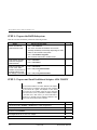
Comprehensive RoadMap Method
This comprehensive roadmap lists each installation step required, and points to the
chapter of this guide that provides more detail, to serve as the master procedural reference
guide for establishing a Secure Path environment.
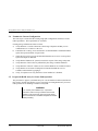
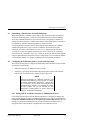
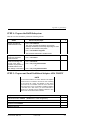
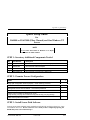
Table 2–1 Secure Path for Windows NT - ROADMAP
STEP
PERFORM THIS PROCEDURE…
DESCRIBED IN…
1
All Pre-Installation steps:
Verify Secure Path Requirements
•
Inventory the Secure Path Kits
•
Prepare the RAID Array for Secure Path
•
Chapter 3
2
Configure the RAID subsystem for Secure Path and
Install the Secure Path Software
Chapter 4
3
Install the Secure Path Hardware
Chapter 5
4
Monitor and Manage the Secure Path Environment,
Using the Secure Path Manager to…
Chapter 6
•
•
•
•
•
Check the Vitality of the Two SCSI Paths
Check/Assign Disk I/O SCSI Paths
Balance Disk I/O Between SCSI Paths
Monitor Automatic Failover Activity
Enable AutoFailback (and/or perform manual failback)
EK–WNTMP–MH. D01
123995–002
2–1
3
Pre-Installation Steps
This section addresses the preparation needed before installing and configuring the Secure Path
components.
3.1
Summary
The procedures described in this guide require that you have already installed your
storage subsystem in a single host/single path configuration or a dual host cluster/single
path configuration. It is further required that you have created storagesets on the
subsystem using either the StorageWorks Command Console (SWCC) or Command Line
Interface (CLI) and have also partitioned and formatted these drives with the Windows
NT Disk Administrator. For complete information about setting-up your subsystem in a
single path/single host environment please refer to the Getting Started guide shipped with
your StorageWorks Solutions platform kit.
The pre-installation steps required to support a Secure Path environment are:
• Verify the Secure Path Requirements
• Inventory the StorageWorks Kits Required for Secure Path
• Prepare the RAID Array for Secure Path Operation
3.2
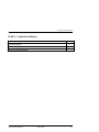
Verify the Secure Path Requirements
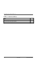
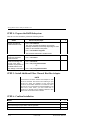
Please verify that the Secure Path requirements listed in Table 3-1 are met.
Table 3–1 Secure Path Prerequisites
Host Feature
Platform
Operating System
Secure Path Software
RAID Storage
Subsystem
SCSI Host Adapters
(and adapter driver)
EK–WNTMP–MH. D01
Requirement
One or two (Intel or Alpha) host server(s)
Microsoft Windows NT Enterprise Edition, Version
4.0, SP3
StorageWorks Secure Path Software Kit v2.2 for
Windows NT (Kit # QB-669AA-SA)
At least one StorageWorks dual-redundant
UltraSCSI RA7000 / ESA10000 or Fibre Channel
RAID Array 8000 or ESA12000 installed and
configured for single path operation.
Two identical Host Adapters. Supported models:
Adaptec AHA-2944UW (for Intel or Alpha servers)
StorageWorks KGPSA (for Intel or Alpha servers)
123995–002
3–1
StorageWorks Secure Path for Windows NT
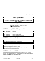
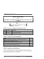
Table 3–1 Secure Path Prerequisites (cont)
Additional Items
Interconnect Hardware
RAID Hardware
Service Tools
Technical
Documentation
Requirement
As required
Cables supplied with host RAID Array Platform kit
Appropriate tools to service your equipment
The reference guides for your RAID subsystem, the
host server and the Windows NT software
supplement this installation guide.
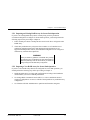
NOTE
With the exception of controller-based partitioning, RAID
software, and system boot disk support, all RAID Array
features supported for single path environments are also
supported with multipath environments.
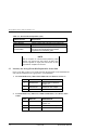
3.3
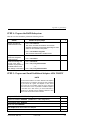
Inventory the StorageWorks Kits Required for Secure Path
Please verify that you have received the following StorageWorks Secure Path hardware
and software installation kit(s) appropriate to your installation:
1.
For SCSI RAID Array 7000 or ESA 10000 with one Windows NT Server
QTY.
2.
PART NO.
DESCRIPTION
1
QB-669AA-SA
Secure Path for Windows,
version 2.2
1
AHA2944UW
UltraSCSI Host Adapter
1
SWXKT-FA
RAID SCSI Connection Kit
For SCSI Raid Array 7000 or ESA 10000 with Windows NT Clusters and YCables.
QTY.
3–2
PART NO.
DESCRIPTION
1
QB-669AA-SA
Secure Path for Windows,
Version 2.2
2
AHA2944UW
UltraSCSI Host Adapter
1
SWXKT-DF
Cluster RAID Connection Kit
123995–002
EK–WNTMP–MH. D01
Chapter 3. Pre-Installation Steps
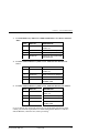
3.
For SCSI Raid Array 7000 or ESA 10000 with Windows NT Clusters and SCSI
Hubs
QTY.
4.
PART NO.
DESCRIPTION
1
QB-669AA-SA
Secure Path for Windows,
version 2.2
2
AHA2944UW
UltraSCSI Host Adapter
1
DS-DWZZH-03
UltraSCSI 3-port Hub
1
SWXKT-EA
UltraSCSI Hub Cluster RAID
Connection Kit
For Fibre Channel Raid Array 8000 or ESA 12000 with One Windows NT
Server
QTY.
5.
PART NO.
DESCRIPTION
1
QB-669AA-SA
Secure Path for Windows,
version 2.2
1
KGPSA-BC
Fibre Channel Host Adapter
1
DS-DHGGB-AA
Fibre Channel Hub
1
DS-DXGK2-SA
Fibre Channel Connection
Kit GBIC 2*2M
For Fibre Channel Raid Array 8000 or ESA 12000 with Windows NT Clusters
QTY.
PART NO.
DESCRIPTION
1
QB-669AA-SA
Secure Path for Windows,
version 2.2
2
KGPSA-BC
Fibre Channel Host Adapter
1
DS-DHGGB-AA
Fibre Channel Hub
1
DS-DXGK1-SA
Fibre Channel Connection
Kit GBIC 3*2M
If you are missing any component required for your Secure Path environment, please
contact your local sales representative or call the StorageWorks Resource Center at 1800-STORWOR (1-800-786-7967) before proceeding.
EK–WNTMP–MH. D01
123995–002
3–3
StorageWorks Secure Path for Windows NT
3.4
Examine the Current Configuration
The next step is to ensure that the existing single path configuration conforms to Secure
Path requirements. The requirements are as follows:
Existing storage infrastructure must be robust –
a)
Verify that there is a serial connection to the storage subsystem and that you can
communicate to it via SWCC or the CLI.
b) Launch the NT event log viewer and check to see that HSZdisk is installed and that it
reports the expected number of logical units.
c)
Check the NT event log viewer and determine that there are no error events reported
by the host adapter or HSZdisk.
d) Verify that the Windows NT system (boot) disk is not part of the storage subsystem.
e)
Verify that none of the LUNs are partitioned by the storage controller hardware.
f)
Verify that none of the NT volume sets use software RAID or use extended volumes.
g) Verify that the server has the TCP/IP protocol installed and that the server is
available on the network by pinging it.
h) Verify, for Alpha servers only, that FX!32 is not installed or is disabled.
3.5
Prepare the RAID Array for Secure Path Operation
The procedures to prepare your RAID Array for a Secure Path environment (described in
this section), depend upon whether you are converting an existing RAID Array to Secure
Path operation or are installing a brand new subsystem.
WARNING
If you currently have a RAID Array in a production
environment, which is being converted to Secure Path
operation, make sure that all users have logged off the
server and that all I/O to the RAID subsystem has ceased
before proceeding.
3–4
123995–002
EK–WNTMP–MH. D01
Chapter 3. Pre-Installation Steps
3.5.1 Preparing an Existing RAID Array for Secure Path Operation
If you have an existing RAID Array that is currently being used in a production
environment and plan to reconfigure for Secure Path operation, you should perform the
following steps before proceeding to Chapter 4:
1.
Follow normal procedures to backup the data stored on all drives configured on the
RAID Array.
2. Check that your RAID Array subsystem does not make use of controller-based
partitioning. Partitioned storagesets and partitioned single-disk units are not
supported in Multiple-Bus failover, dual-redundant configurations. Re-configure to
eliminate any controller-based partitions.
WARNING
Before you delete any partitions on the RAID Array, backup
your data and then use Windows NT Disk Administrator to
delete the partition(s) from the drives before you delete the
storage unit(s) from the RAID Array configuration.
3.5.2 Preparing a New RAID Array for Secure Path Operation
If you have a new RAID Array that will be configured for Secure Path operation, you
should perform the following steps before proceeding to Chapter 4:
1.
Install the RAID Array in a single path configuration according to the installation
documentation you received with the platform kit.
2.
Use StorageWorks Command Console (SWCC) or CLI to establish the desired
storageset configuration. Do not use controller-based partitions in your RAID Array
configuration.
3.
Use Windows NT Disk Administrator to partition and format the storagesets.
EK–WNTMP–MH. D01
123995–002
3–5
4
Installing Secure Path Software
This chapter describes the software configuration procedures required to establish Secure Path
operation to a RAID Subsystem.
4.1
Summary
The following sections describe the software configuration procedures required for your
Secure Path storage environment, which are as follows:
•
Install the StorageWorks Secure Path software on the host server(s)
•
Establish a serial link to the RAID subsystem
•
Set RAID controllers to multiple-bus failover mode
•
Prefer the paths of the storagesets (units) to the RAID controllers
After performing these procedures in sequence, the software configuration of your Secure
Path storage environment will be complete.
4.2
Installing the Secure Path Software
This section describes the Secure Path software; how to install the Secure Path driver and
agent, and how to install the Secure Path Manager.
4.2.1 Description of the Secure Path Software
Secure Path for Windows NT consists of a kernel mode driver that is responsible for
directing I/O to the desired path, and for changing paths whenever the driver detects a
failure in a redundant path.
Secure Path for Windows NT is managed by a client/server management application
which requires that TCP/IP be installed in the Windows NT server attached to the Storage
where the Secure Path agent is installed; and on the management station on which the
Secure Path Manager graphical user interface is installed.
The Secure Path user interface and agent (client/server) may be installed in the same
server, as long as the agent is installed on the server that is attached to the storage
subsystem to be managed.
EK–WNTMP–MH. D01
123995–002
4–1
StorageWorks Secure Path for Windows NT
4.2.2 Installing the Secure Path Driver and Agent
The following section describes how to install the Secure Path drivers and configuration
management agent on the host server.
1.
Insert the StorageWorks Secure Path Software (v2.2) for WNT distribution CD in your
CD-ROM driver.
2.
If you have CD AUTORUN enabled on your server, the Secure Path setup program
will start automatically. Otherwise, Choose “Run” from the START menu and enter
the command shown below, substituting your CD-ROM’s drive letter for the one
shown.
Drive_Letter:\SPINSTAL \SETUP.EXE
When the setup starts, choose the server install option. The server option will install
the drivers and the agent required by Secure Path.
Be prepared to designate those clients that you wish to allow to manage the host.
These names have to be fully qualified, for example “myserver.mydomain.com”.
There are many ways to configure TCP/IP on your network. They include a) host
files on servers and clients and b) DNS, with NetBios using DNS resolution. Check
with your system administrator to assure proper network configuration.
3.
Make sure to enter a validation password. For cluster configurations make sure the
password is the same for each member of the cluster.
4.2.3 Installing the Secure Path Manager
The following section describes how to install the Secure Path management application
on the management station. The management application can be installed on the host
server, or on a separate management station.
1.
Insert the StorageWorks Secure Path Software (v2.2) for WNT distribution CD in your
CD-ROM driver.
2.
If you have CD AUTORUN enabled on your server, the Secure Path setup program
will start automatically. Otherwise, Choose “Run” from the START menu and enter
the command shown below, substituting your CD-ROM’s drive letter for the one
shown.
Drive_Letter:\SPINSTAL \SETUP.EXE
When the setup starts, choose the client install option. The client option will install the
Secure Path Management graphical user interface.
4–2
123995–002
EK–WNTMP–MH. D01
Installing Secure Path Software
4.3
Establishing a Serial Link to the RAID Subsystem
While StorageWorks Command Console (SWCC) may be used to define and configure
storagesets on the subsystem, it cannot be used to establish a Secure Path environment.
Thus, the Command Line Interface (CLI) must be used to configure the controllers for
multiple-bus mode operation. Controller status may be obtained through use of the SWCC
CLI Window or a terminal emulation program via serial connection.
Use StorageWorks Command Console (serial connection/CLI Window) or a terminal
emulation program such as Hyperterminal to establish a serial connection to the
subsystem. You will use this connection to issue “CLI” commands to the subsystem.
You may use a serial line connection from the host server or from any PC workstation.
Please refer to the Command Console User’s Guide or the Getting Started Guide shipped
with your platform kit for information on how to setup and use a serial connection and the
“CLI Reference Manual ” for complete information on CLI commands and syntax.
4.4
Configuring the RAID Subsystem for Secure Path Operation
This section describes how to configure the RAID subsystem controllers for a Secure Path
environment, which includes:
•
Setting the controllers to multiple-bus failover mode
•
“Preferring” (specifying) which RAID controller (SCSI bus path or Fibre Channel
loop) the I/O of each disk will be assigned to upon system boot.
NOTE
Partitioned storagesets and partitioned single-disk units
(controller-based partitioning) cannot function in multiplebus failover dual-redundant configurations. Because they
are not supported, you must delete and re-configure these
storagesets before configuring the controllers for multiplebus failover. Make sure you use Windows NT Disk
Administrator to delete partitions on drive(s) before you
delete the corresponding storageset(s).
4.4.1 Setting HSZ70 or HSG80 Controllers to Multiple-bus Failover
Secure Path operation requires that the RAID controllers be configured for multiple-bus
failover mode through use of the Command Line Interface (CLI). This is accomplished by
issuing four individual commands, in the sequence provided in this section, at the CLI
prompt. For clarity, the command lines are presented in bold text, and followed by a
description of the action produced or required after each command is issued.
EK–WNTMP–MH. D01
123995–002
4–3
StorageWorks Secure Path for Windows NT
HS*** > set nofailover
The “other” controller will shutdown and must be manually restarted by momentarily
depressing the reset button on the controller’s front panel. Wait for 2 minutes for the
controller to boot before proceeding.
HS*** > set multibus copy=this
The controllers will restart in multiple-bus mode.
After the other controller has restarted, verify that both controllers are configured for
multiple-bus mode by issuing the following commands:
HS*** > show this
HS*** > show other
The controllers are now configured for multiple-bus operation.
4.4.2 “Preferring” Storage Unit Paths
To complete the multiple-bus configuration setup, you must “prefer” (assign) storage
units to one or the other controller to specify which controller is used to access units at
system boot time. The preferred_path unit attribute assigns units to either “this” or the
“other” controller. In effect, this procedure specifies on which p ath (controller, SCSI bus,
and host adapter) the I/O will travel.
Initially, it is recommended that you balance the available storagesets between the busses.
As storage demands are defined and individual drive throughput requirements are
understood, adjustments to the disk I/O path configuration may be made using the
StorageWorks Secure Path Manager, as described in Chapter 6 of this guide.
Use the following command to obtain a list of all units defined in the RAID subsystem:
HS***> show units
Use the following command to specify PREFERRED_PATH for units:
HS*** > set (unit #) preferred=this
- or HS*** > set (unit #) preferred=other
Repeat for each configured storage unit in your configuration. Power must be cycled
on the RAID Array cabinet for the Preferred Path settings to take effect.
You have completed the software configuration required to support your Secure Path
environment. Proceed to Chapter 5 to cable the second path. Then you will be ready to
monitor and manage Secure Path activity using the StorageWorks Secure Path Manager,
as described in Chapter 6 of this guide.
4–4
123995–002
EK–WNTMP–MH. D01
5
Installing Secure Path Hardware
This chapter provides the procedures for installing and terminating a second individual I/O path
between a StorageWorks RAID subsystem and an NT host server or a Microsoft Cluster Server,
where currently a single I/O path exists.
WARNING!
Follow normal procedures to power off your server prior to
cabling.
5.1
Summary
Configuring Secure Path hardware components consists of three main tasks to be
performed in sequence, as described in the following sections.
5.2
1.
Prepare and Install the Second Host Adapter
2.
Cable the Secure Path Hardware Components
3.
Verify the Secure Path Hardware Configuration
Prepare and Install the Second Host Adapter
To complete your Secure Path installation you must install a second host (bus) adapter in
the server(s).
Prior to installing the second host adapter into the server, the host adapter must be
prepared for Secure Path operation.
For SCSI Adaptec AHA2944UW host adapters:
•
Setting/Verifying SCSI Host Adapter Termination
•
Disabling SCSI Bus Reset
•
Disabling SCSI Host Adapter BIOS
•
Set Start Unit to “NO”
For Fibre Channel KGPSA host adapters:
•
No preparation required
EK–WNTMP–MH. D01
123995–002
5–1
StorageWorks Secure Path for Windows NT
5.2.1 Setting Up SCSI Host Adapters
NOTE
You must assure that the connection between host adapters
on both servers is consistent. Use the PCI slot numbering
on your servers as a guide. The adapters on each server
that connect to one controller should be in the same PCI
slot in each server. If it is not possible to install the adapters
in the same slot in each server, you must install them in
sequence. For example, the first adapters installed in each
server must connect to the same controller.
Refer to the documentation supplied with your adapter to help you configure the
following parameters. Make sure that these settings are identical for each host adapter.
For SCSI host adapters:
1.
Termination is enabled unless you are using Y-cables with external termination. If
you are using Y-cables with external termination then you must disable termination
on the host bus adapter.
2.
SCSI bus resets following board initialization (power-on reset) are disabled.
3.
SCSI host adapter BIOS is disabled.
The host adapters are now prepared for Secure Path operation. Follow the adapter
vendor’s recommended procedure to install the second adapter in your server’s system
bus.
5.3
Installing Cables and Termination
Choose from one of the following subsections to properly cable your Secure Path
configuration:
If you are installing an RA7000 or ESA10000 (SCSI) and One Windows NT server,
choose section 5.3.1
If you are installing an RA7000 or ESA10000 (SCSI) and a Windows NT Cluster with
SCSI Y-cables, choose section 5.3.2
If you are installing an RA7000 or ESA10000 (SCSI) and a Windows NT Cluster with
SCSI Hubs, choose section 5.3.3
If you are installing an RA8000 or ESA12000 (Fibre Channel) and one Windows NT
Server, choose section 5.3.4
If you are installing an RA8000 or ESA12000 (Fibre Channel) and a Windows NT
Cluster, choose section 5.3.5
5–2
123995–002
EK–WNTMP–MH. D01
Chapter 5. Installing Secure Path Hardware
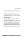
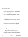
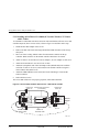
5.3.1 Installing an RA7000 or ESA10000 (SCSI) and One Windows NT Server
To establish two individual SCSI busses between a single Windows NT host server and a
RAID subsystem, where one bus exists, reference Figure 5-1 and follow these steps:
1.
Install the host adapter in the server.
2.
Remove the link cable connecting both HSZ70 RAID controllers in the subsystem.
3.
Connect a terminator (H8863-AA) to the remaining tri-link connector of the
controller that is currently connected to the host server.
4.
Attach end of the UltraSCSI cable (BN37A-05) to the tri-link connector on the
controller in the RAID subsystem that is not currently connected to the host server.
5.
Connect end of the .2M adapter cable (BN38-E-0B) to the available end of the
UltraSCSI cable.
6.
Attach the other end of the .2M adapter cable to the available SCSI host adapter
board resident in the host server.
7.
Verify that the terminator (H8863-AA) pre-existing in the newly-cabled controller is
firmly attached into its tri-link connector.
8.
Reboot the host server.
The Secure Path solution is now properly prepared, cabled and terminated.
Figure 5–1 Secure Path Hardware Interconnect – SCSI Single Server
Windows NT
Server
HD68 Pin
SCSI RA7000 Subsystem
(2 controllers)
H8863-AA Terminators
SCSI Host
Bus
Adapters
BN38E-0B
0.2m Adapter Cable
Additional
Hardware
BN37A-05
UltraSCSI Cable
SHR-1275
NOTE
In Figure 5-1, notice that the link cable between the two
RAID controller boards has been removed, and that both
busses are terminated on the controller.
EK–WNTMP–MH. D01
123995–002
5–3
StorageWorks Secure Path for Windows NT
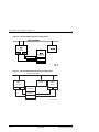
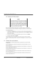
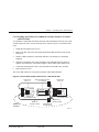
5.3.2 Installing an RA7000 or ESA10000 (SCSI) and a Windows NT Cluster
with Y-Cables.
To establish two individual SCSI busses between clustered Windows NT host servers and
a RAID subsystem, where one bus exists, reference Figure 5-2 and follow these steps:
1.
Install the Host Bus Adapter in the servers.
2.
Remove the link cable interconnecting both HSZ70 RAID controllers in the storage
subsystem.
3.
Move one of the existing VHDCI cables from the bottom controller to the top
controller. Both connectors on the bottom controller should now be unused.
4.
Attach Y-cables to each of the new host bus adapters, one new adapter in each server.
5.
Attach SCSI terminators to one end of each Y-cable.
6.
Attach the (compatible) end of the .2M adapter cable (BN38E-0B) to the available
end of the Y-cable of one server, and extend it to the bottom controller using the 5
meter VHDCI cable (BN37A-05)
7.
Attach the VHDCI/HD68 5 meter cable between the remaining Y-cable and the
bottom controller.
8.
Reboot the host servers.
The Secure Path solution is now properly prepared, cabled and terminated.
Figure 5–2 Secure Path Hardware Interconnect – SCSI Cluster Y-Cable
Windows NT SCSI RA7000 Subsystem
(2 controllers)
Server "A"
Windows NT
Server "B"
HD68 Pin
SCSI Host
Bus
Adapters
HD68 Pin
SCSI Host
Bus
Adapters
BN21W-0B Y-Cable
Terminator
Additional
Hardware
BN21W-0B Y-Cable
Cable
Terminator
BN38E-0B
0.2m Adapter Cable
BN37A-05
UltraSCSI Cable
SHR-1276
5–4
123995–002
EK–WNTMP–MH. D01
Chapter 5. Installing Secure Path Hardware
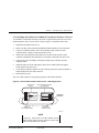
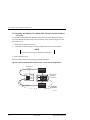
5.3.3 Installing an RA7000 or ESA10000 (SCSI) and a Windows NT Cluster
with SCSI Hubs.
To establish two individual SCSI busses between clustered Windows NT host servers and
a RAID subsystem, where one bus currently exists, reference Figure 5-3 and follow these
steps:
1.
Install the host adapter in the servers.
2.
Remove the link cable interconnecting both HSZ70 RAID controllers in the storage
subsystem.
3.
Install a VHDCI terminator on the both controllers (one already has a terminator
installed)
4.
Attach the (compatible) end of the .2M adapter cable (BN38E-0B) to the host bus
adapters, and extend it to a SCSI hub using the 5 meter VHDCI cable (BN37A-05)
5.
Connect the remaining port of the 3 port SCSI hub to the RAID Array controller.
6.
Reboot the host servers.
The Secure Path solution is now properly prepared, cabled and terminated.
Figure 5–3 Secure Path Hardware Interconnect – SCSI Cluster Hub
Windows NT
Server "A"
SCSI RA7000 Subsystem
(2 controllers)
HD68 Pin
SCSI Host
H8863-AA
Terminators
Bus
Adapters
BN38E-0B
0.2m Adapter Cable
Additional
Hardware
Windows NT
Server "B"
HD68 Pin
SCSI Host
Bus
Adapters
BN38E-0B
0.2m Adapter Cable
BN37A-05
UltraSCSI Cable
BN37A-05
UltraSCSI Cable
DS-DWZZH-03
ULtraSCSI Hub
SHR-1277
EK–WNTMP–MH. D01
123995–002
5–5
StorageWorks Secure Path for Windows NT
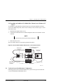
5.3.4 Installing an RA8000 or ESA12000 (Fibre Channel) and One Windows
NT Server
To establish two individual Fibre Channel busses between a single Windows NT host
server and a RAID subsystem, where one bus currently exists, reference Figure 5-4 and
follow these steps:
1.
Install the host adapter in the server.
2.
Connect the second hub to the second host adapter and to the second controller.
NOTE
You must use only one set of ports in the controller pair.
3.
Reboot the host server.
The Secure Path solution is now properly prepared and cabled.
Figure 5–4 Secure Path Hardware Interconnect – Fibre Channel Single Server
Windows NT
Server
Fibre RA8000
Subsystem
(2 controllers)
KGPSA
Fibre Host
Bus
Adapters
Fibre Cable
Fibre Hub
Additional
Hardware
SHR-1278
5–6
123995–002
EK–WNTMP–MH. D01
Chapter 5. Installing Secure Path Hardware
5.3.5 Installing an RA8000 or ESA12000 (Fibre Channel) and a Windows NT
Cluster
To establish two individual Fibre Channel loops between clustered Windows NT host
servers and a RAID subsystem, where one bus currently exists, reference Figure 5-5 and
follow these steps:
1.
Install the host adapters in the servers
2.
Connect the second hub to the second host adapter in each server and to the second
controller.
NOTE
You must use only one set of ports in the controller pair.
3.
Reboot the host servers.
The Secure Path solution is now properly prepared and cabled.
Figure 5–5 Secure Path Hardware Interconnect – Fibre Channel Cluster
Fibre RA8000 Subsystem
(2 controllers)
Windows NT
Server A
Windows NT
Server B
KGPSA
Fibre Host
Bus
Adapters
KGPSA
Fibre Host
Bus
Adapters
Additional
Hardware
Fibre Cable
Fibre Cable
Fibre Hub
SHR-1279
5.4
Verify the Secure Path Hardware Configuration
Following system reboot, check the Windows NT system event log for successful start
events for the RaiDisk and HszDisk drivers.
EK–WNTMP–MH. D01
123995–002
5–7
6
Using StorageWorks Secure Path Manager
This chapter describes how to use StorageWorks Secure Path Manager to monitor and manage a
StorageWorks Secure Path for Windows NT environment.
6.1
About StorageWorks Secure Path Manager (SPM)
NOTE
This chapter assumes that RAID Array storagesets have already
been configured using SWCC or CLI and that the drives have been
partitioned and formatted with Windows NT Disk Administrator.
These procedures are described in the Getting Started guide
shipped with your subsystem.
StorageWorks Secure Path Manager is a Graphical User Interface (GUI) utility that:
•
Reports the status of the two paths
•
Facilitates balancing I/O between the two bus paths
•
Reports disk status (path assignment, failover, and failback activity)
•
Provides manual and auto-failback capabilities
It is recommended that Secure Path Management application remain active (or
minimized), to provide continuous Secure Path status monitoring.
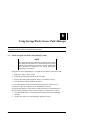
To monitor and manage a Secure Path environment using Secure Path Manager as
described in the following sections, reference Figure 6-1 and proceed as follows:
1.
From the START menu, select the Programs\ StorageWorks\SecurePath Mgr
submenu.
2.
Double-click on the Secure Path Manager application ICON.
EK–WNTMP.MH. D01
123995–002
6–1
StorageWorks Secure Path for Windows NT
Figure 6–1 Invoking Secure Path Manager
6.2
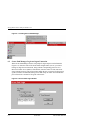
Secure Path Manager Login and Agent Connection
When Secure Path Manager starts it will prompt for login and password information
(Figure 6-2). Enter the name of the Secure Path configured host (server) you wish to
manage in single host environments, along with the corresponding password. For
Microsoft Cluster Server (MSCS) environments, enter the names of each cluster host
along with the password. The password must match the one you entered for the agent or
agents (in cluster environments) during Secure Path setup. In cluster environments this
password must be common for all agents in the cluster.
Figure 6–2 Secure Path Login Window
6-2
123995-002
EK-WNTMP-MH. D01
Chapter 6. Using Secure Path Manager
Each instance of Secure Path Manager is capable of managing one single host
configuration with multiple storage subsystems or a dual-host MSCS cluster with multiple
subsystems. In order to manage multiple single host or MSCS configurations, additional
instances of the Secure Path Manager are required, one for each single host or pair of
clustered hosts.
To change an agent password you must run the Secure Path Agent Configuration utility
located in the Start menu along with the Secure Path Manager application. Once you have
changed an agent’s client access list and/or password following initial setup, you must
stop and restart the agent using the Services Applet located in Control Panel. Find and
select the Secure Path Agent in the list of services and push the Stop button (Figure 6-3).
Once the agent has stopped, select Secure Path Agent again and press the Start button.
The agent will now update its client and/or password database. In cluster environments
make sure you do this for the agent on each host.
Figure 6–3 Stopping the Secure Path Agent
If you experience problems connecting the client with the Secure Path agent/s, please
refer to Appendix C, Troubleshooting Secure Path Connection Problems , for help.
EK-WNTMP-MH. D01
123995-002
6-3
StorageWorks Secure Path for Windows NT
6.3
Host Connection Status Monitor
As shown in Figure 6-4, Secure Path Manager will display, immediately below the tool
bar, an icon representing a connection to each active Secure Path host. If a connection is
lost to a host, an "X" will appear over that host’s icon. Secure Path Manager periodically
attempts to reconnect to selected hosts and will remove the "X" if the connection state is
re-established.
In cluster configurations, if Secure Path Manager loses connection to one of the hosts, it
will display the Secure Path configuration state based on information received from the
surviving host.
Figure 6–4 Secure Path Host Connection Icons
6-4
123995-002
EK-WNTMP-MH. D01
Chapter 6. Using Secure Path Manager
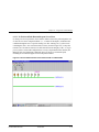
6.4
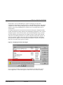
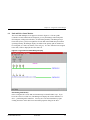
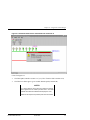
Path and Drive Status Monitor
The Secure Path Manager screen appears as shown in Figure 6 -6. The two paths
(Controller A and Controller B) are displayed green by the Manager when both paths
(host adapters, cabling and controllers), are functioning normally. The Manager keeps
track of the primary path (bus assignment) for each disk in the RAID subsystem. When
operating normally, the Manager displays each disk on the primary path to which it has
been assigned, as a disk icon, shaded yellow and gray. If a drive letter has been assigned
to the disk, it will be displayed above the disk icon.
Figure 6–5 Typical Secure Path Manager Display
Determining Disk Identity
Drives configured in a Secure Path environment may be identified three ways. If you
hover the cursor over a disk icon, The Manager will display the various identities of a
drive – port/bus/target/lun and disk #. You may also view this information by rightclicking the mouse on the disk icon to launch the properties dialog for the drive.
EK-WNTMP-MH. D01
123995-002
6-5
StorageWorks Secure Path for Windows NT
The port/bus/target/lun information refers to the physical identity of the drive’s
corresponding storageset (unit) as designated by the RAID Array subsystem. The disk #
refers to the number assigned to a drive by Windows NT’s Disk Administrator and the
drive letter, appearing above the drive icon, is assigned to that partition (if one exists). If a
drive has more than one partition they will appear above the drive as well. This drive
information should allow you to quickly map storageset to operating system identity and
determine which storagesets are currently serviced through each path.
6.5
Assigning New Primary Paths to Drives
To assign a new primary path to a drive using the Manager, proceed as follows:
1.
Use the left mouse key to select the icon of the disk that is to receive a new primary
path assignment (the icon will become a null-circle when selected).
2.
Drag the disk icon from its current primary path to the alternate path displayed on the
screen.
3.
Drop the disk icon, anywhere you see the squared arrow along the “new” primary
(formerly alternate) path, by releasing the mouse key. (The icon turns gray while in
transition, and the cursor becomes an hour-glass).
When the primary path re-assignment of a disk completes, its icon will appear in its
original form, shaded gray and yellow, on the new path. (It may appear above or beneath
the path line, depending on your exact placement of the mouse). Repeat this procedure for
each disk that is to be assigned a new primary path. A maximum of 24 drives can be
assigned between both paths.
The Secure Path Manager will not permit a new primary path assignment to a failed path.
If an attempt is made to move a drive to a failed path the Manager will return the drive to
the original path. A popup will also appear stating that the move was not successful.
NOTES
The display is refreshed every 90 seconds, and can be
refreshed immediately using the View/Refresh pull-down
menu of the Manager window or by depressing the F5 hot
key.
6-6
123995-002
EK-WNTMP-MH. D01
Chapter 6. Using Secure Path Manager
6.6
Balancing the I/O Load Between Paths
As the storage demands of your Secure Path environment are defined and individual drive
throughput requirements are understood, it is recommended that the disks generating the
highest I/O loads be evenly balanced between the two paths to maximize overall
throughput. The Manager may be used to statically load balance your Secure Path
configuration by following the procedure noted below.
1.
Identify “hot” drives - those that consistently experience the greatest I/O load while
running workloads typical of your production environment. Enable Windows NT disk
performance statistics, if you have not done so already, by issuing “diskperf –y”
from a command window and restarting your system. Next, use Windows NT
Performance Monitor to characterize individual drive loading in terms of throughput
(I/O’s per second) and/or bandwidth (bytes per second), whichever is more
appropriate for your application.
2.
Note the path assignments of hot drives.
3.
Balance the overall I/O load by evenly distributing (reassigning drive primary path),
as much as possible, the hot drives between the two paths. Run your workload,
monitor, and re-adjust as necessary.
Reference Section 6.5 for the procedures to assign a new primary path to a drive using the
Secure Path Manager.
6.7
Defining a Persistent Secure Path RAID Array Drive Configuration
When the primary path for a drive is changed using the Manager, the preferred_path
(refer to section 4.4.2) assignment for the corresponding storage unit on the RAID Array
does not change. If the preferred_path is not changed to the new path, the unit will revert
to its original preferred_path if both the RAID Array and host server are power cycled
together. To make the primary path assignment persistent for those drives you have
reassigned with the Manager, re-set the preferred_path attribute for the corresponding
storage unit on the RAID Array. Use the following procedure:
1.
Use the CLI command show units to show the preferred_path settings for all units.
This command will also indicate which controller each storageset is currently online
with (“this” or “other).
2.
Next, use the CLI command set unit# preferred=this/other to change the preferred
path attribute to the appropriate path. For instance, if a storage unit is reported as
being “online to other controller” but is preferred to the “this” controller, then you
should change the preferred_path attribute to the “other” controller.
3.
Repeat this procedure for each storage unit that is online to a path that is not its
preferred path. It is not necessary to restart your server or RAID Array to perform this
procedure.
EK-WNTMP-MH. D01
123995-002
6-7
StorageWorks Secure Path for Windows NT
6.8
Automatic Failover
When a path fails, (Secure Path software detects the loss of drive I/O due to adapter, cable
or controller malfunction), the Secure Path software will:
•
Perform an automatic failover and move the effected drive/s to the alternate path.
•
Log failover event/s in the Windows NT system Event Log.
•
Report the path failure via a Secure Path Manager pop-up message.
•
Reflect the drive/s reassignment to the failover path on the display.
NOTE
Check the Windows NT system and application Event Logs
for entries generated by the Secure Path software to help in
determining which component(s) of the path have
malfunctioned. Look for entries by the HszDisk and RaiDisk
drivers.
6.8.1 Automatic Failover Detection and Status Reporting
The Secure Path software continuously monitors the operational status of drives
configured on each path. If the Secure Path software detects the failure of an I/O to
complete for a drive, it will immediately move that drive to its alternate path and reroute
outstanding I/O accordingly. Following the occurrence of any drive failure, the Manager
will reflect the updated Secure Path configuration within its 90 second refresh interval, or
sooner if the user depresses the F5 key.
When the Manager discovers the failover of at least one drive, it generates a pop-up
message and designates the path as failed by changing its color from green to yellow or
red. Because the Secure Path software detects path failure through failed I/O operations ,
only those drives with I/O active at the time of the failure will failover . Those without
active I/O will remain on the failed path until I/O is generated to them. When all drives
have been failed-over, the Manager will color the failed path red.
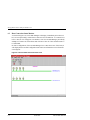
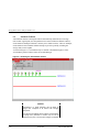
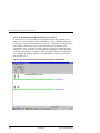
As shown in Figure 6-6, a failover is indicated by the Secure Path Manager in three ways:
6-8
1.
The failed path changes from green to red, or yellow if inactive drives remain on the
path.
2.
The affected disk icons relocate from their primary path to the alternate path,
indicating that disk I/O has been failed-over to the alternate path.
3.
On the alternate path, the disk icons that have been failed-over from their primary
path reappear, shaded green.
4.
A Secure Path Manager pop-up message appears to report the failure.
123995-002
EK-WNTMP-MH. D01
Chapter 6. Using Secure Path Manager
Figure 6–6 Automatic Disk Failover from Failed Path Controller A
Colors for Figure 6-6:
•
The failed path (Controller A) turns red, (or yellow if inactive disk/s remains on it).
•
The failed-over disks appear green on their alternate path (Controller B).
NOTES
For a quick reference of the disk colors and their meaning,
select Legend from the “VIEW” pull-down menu. The three
possible drive states are identified and displayed in color.
Reference the Help files for possible path colors and states.
EK-WNTMP-MH. D01
123995-002
6-9
StorageWorks Secure Path for Windows NT
6.9
Automatic Failback
Auto-failback monitors a failed path and will automatically return failed-over storage
units to their original path, once the path has been restored. With auto-failback enabled,
Secure Path will attempt to failback a unit only twice within one hour. After two attempts,
Secure Path will cancel further failback attempts to prevent repeatedly switching the
storage unit(s) between paths.
As shown in Figure 6-7, auto-failback may be enabled or disabled through use of the
AutoFailBack pull-down menu in the Secure Path Manager.
Figure 6–7 Enabling the Auto-Failback Feature
NOTES
Auto-failback is a global parameter that will affect all
storage units configured on all Secure Path managed
subsystems.
Even with the auto-failback feature enabled, manual failback
of storage units (described in Section 6.9) can still be
performed at any time, once the path’s integrity is validated.
6-10
123995-002
EK-WNTMP-MH. D01
Chapter 6. Using Secure Path Manager
6.10 Manual Failback and Status Reporting
Once a failed path is restored, the disks that had been failed-over to an alternate path may
be failed-back manually, one at a time. Manual failback can be used as an alternative to
the auto-failback feature, enabling the administrator to fully validate the integrity of the
restored path before returning the storagesets. The manual failback feature may also be
used when the auto-failback feature is enabled.
NOTE
For a failed path display to return to the normal (green)
state, the path must be restored and one or both of the
following events must occur:
•
All of the failed-over disks are failed back to it.
•
The NT server is rebooted.
Failed-over drives may be restored to their primary path using one of the four failback
methods described in this section.
Manual Failback Methods
•
Failback Method 1: Double-click on the disk (icon) to be failed-back.
•
Failback Method 2: From the “FAILBACK” pull-down menu, select the Failback
option; select the disk, then click “OK”.
•
Failback Method 3: In the Manager Toolbar, click on the failback button (white
button with an arrow and red line); select the disk, then click “OK”.
•
Failback Method 4: Drag-and-drop each failed-over disk icon to its primary path, as
follows:
1.
Use the left mouse key to select the icon of the disk that is to failback to its
assigned primary path (the icon will become a null-circle when selected).
2.
Drag the disk icon from its current, alternate path to the primary path displayed
on the screen (the icon turns gray while in transition, and the cursor changes to a
squared arrow).
3.
Drop the disk icon anywhere along the disk’s primary path by releasing the
mouse key.
If more than one drive requires failback, repeat these steps until all the drives are failedback, and the restored path turns green. As each individual drive returns to its primary
path, the drive icons will return to their normal yellow and gray color. (The disk icon may
appear above or beneath the path line, depending on your exact placement of the mouse).
The failback path’s color will not return to green until all failed-over drives have been
restored to their primary path.
EK-WNTMP-MH. D01
123995-002
6-11
StorageWorks Secure Path for Windows NT
6.11 Notification when No-Single-Point-of-Failure is Compromised
When a server is booted, Secure Path software interrogates each managed device for its
preferred path information, as well as expecting to discover redundant paths for each
device. In some situations, broken or malfunctioning hardware at boot time may prevent
the operation of one of the paths to one or more StorageWorks RAID Arrays. Since this
situation seriously compromises the integrity of the no-single-point-of-failure capabilities
of your configuration, Secure Path detects and distinguishes between the two possible
occurrences of this condition. Section 6.11.1 describes Secure Path notification in cases
where one or more drives cannot be accessed through their preferred path at boot time.
Section 6.11.2 describes notification in cases where all devices are accessible through
their preferred path, but the redundant path could not be discovered.
Secure Path will provide continuous automatic failover protection for any device which
still has a viable alternate path. However, to maximize the high availability potential of
your Secure Path configuration, corrective action should be undertaken immediately to
eliminate the cause of the failed alternate path. The affected server(s) will need to be
rebooted following corrective action.
In summary, when no-single-point-of-failure is compromised, as indicated by the circled
’M’ icon on one or more devices, or the information icon, Secure Path behaves as follows:
6-12
Secure Path Will…
Secure Path Will Not…
•
automatically failover devices with
viable alternate paths
•
allow a multiple path device to be
reassigned to another path
•
automatically move failed-over device
back to original path if the path
appears healthy and auto-failback
option is enabled
•
allow a failover device to be manually
returned to its original path
123995-002
EK-WNTMP-MH. D01
Chapter 6. Using Secure Path Manager
6.11.1 No Preferred Path Detectable upon Server Boot
If, during server boot operations, Secure Path is unable to detect the preferred path to one
or more devices due to component failure ( i.e., a broken SCSI adapter), it indicates this
condition through the use of a special warning icon. The warning icon, (a yellow circle
containing the letter “M” crossed out with a red line), shown in Figure 6-8, overlays the
normal icon of each device known to be affected. Because the integrity of the no-singlepoint-of-failure Secure Path configuration is severely compromised in this situation, the
Manager locks out all attempts to manually move any device to an alternate path,
including devices that still appear to have both paths available.
Figure 6–8 Secure Path Indicates when Preferred Path is Undetectable
EK-WNTMP-MH. D01
123995-002
6-13
StorageWorks Secure Path for Windows NT
6.11.2 No Redundant Path Detectable upon Server Boot
If, during server boot, Secure Path finds a StorageWorks RAID Array that has devices
which are accessible through their preferred path, but for which a redundant path cannot
be detected, it will place an Information icon next to the “Subsystem” identifier at the top
of the window. Hovering the cursor over the Information icon (a small blue circle
containing the letter “I”) produces a tool tip, as shown in Figure 6-9, identifying which
subsystem(s) is (are) affected by the missing path. The Information icon will appear next
to all Subsystem identifiers, regardless of which subsystem is affected, to insure that the
user is alerted to the problem. All other Secure Path behavior in this case is identical to
that described in 6.11.1.
Figure 6–9 Secure Path Indicates when Redundant Path is Undetectable
6-14
123995-002
EK-WNTMP-MH. D01
Chapter 6. Using Secure Path Manager
6.12 Adding New Storagesets with Secure Path
To add new storagesets to a Secure Path configuration, proceed as follows:
1.
Use StorageWorks Command Console (SWCC) or CLI to create a new storageset/s
on the RAID Array.
2.
Use CLI to assign a preferred path to the new unit, as described in Section 4.4.2.
3.
Use appropriate procedures to add a new volume to the NT server or cluster.
4.
Restart the host server(s) so that Windows NT and the Secure Path software can
configure the new unit.
6.13 Removing a Storageset with Secure Path
1.
Use Windows NT Disk Administrator to delete the partition from the drive to be
removed using appropriate procedures.
2.
Shutdown Windows NT on the host server(s).
3.
Use StorageWorks Command Console (SWCC) or CLI to delete the storageset/s on
the RAID Array.
4.
Reboot the host server(s) to allow the Secure Path software to configure storage
devices.
EK-WNTMP-MH. D01
123995-002
6-15
A
Quick Setup
This section provides simplified installation instructions to enable experienced system integrators
and administrators to quickly establish a Secure Path environment. For a more comprehensive
installation method, please reference the roadmap provided in Chapter 2 of this guide.
About Quick Setup
NOTE
•
You must have completed installation of a SCSI RAID
Array 7000 or a Fibre Channel RAID Array 8000 in a
Windows NT single server or cluster environment with
a single I/O path, and it must be functioning properly.
You must have established a serial line connection to
the RAID Array.
•
Do not proceed until the single path installation is
functioning properly.
•
Do not install Secure Path for Windows in an Alpha
server which has FX!32 installed.
Use the Quick Setup Guide that corresponds to your RAID subsystem type and desired
configuration.
For this type of RAID Array…
And this Windows NT
Configuration…
Use the Quick
Setup Guide
on…
RA7000 or ESA10000 (SCSI)
One Windows NT Server
Page A–2
RA7000 or ESA10000 (SCSI)
Windows NT Cluster with Y-cables
Page A–5
RA7000 or ESA10000 (SCSI)
Windows NT Cluster with SCSI Hub
Page A–8
RA8000 or ESA12000 (Fibre Channel)
One Windows NT Server
Page A–11
RA8000 or ESA12000 (Fibre Channel)
Windows NT Cluster
Page A–13
EK–WNTMP–MH. D01
123995–002
A–1
StorageWorks Secure Path for Windows NT
Quick Setup Guide
for
RA7000 or ESA10000 (SCSI) and One Windows NT Server
NOTE
Do not install Secure Path for Windows in an Alpha
server which has FX!32 installed.
STEP 1: Inventory Additional Components Needed
Qty
Part Number
Description
1
QB-669AA-SA
Secure Path for Windows (version 2.1)
1
AHA2944UW
UltraSCSI Host Bus Adapter
1
SWXKT-FA
RAID SCSI Connection Kit
STEP 2: Examine Present Configuration
✔
Action
Single path configuration functions properly – check event log
Serial line connection available to the controller
StorageSets and NT volumes defined – not hardware partitioned
Windows NT system disk not part of RAID subsystem
TCP/IP protocol installed on Windows NT server
[Alpha servers] FX!32 not installed
STEP 3: Install Secure Path Software
From the Secure Path CDROM, launch \SPINSTAL\SETUP.EXE, and follow directions. Setup
will shutdown the server. Do not restart the server until you have completed preparing the
RAID subsystem, as described in Step 4.
A–2
123995–002
EK–WNTMP–MH. D01
Appendix A. Quick Setup
STEP 4: Prepare the RAID Subsystem
After the server has shutdown, perform the following actions:
Action
Serial Line (CLI) steps
Set the controllers to
multibus failover mode
✔
HS***> set nofailover
The “other” controller will shutdown and must be
manually restarted by momentarily depressing the reset
button on the controller’s front panel .
HS***> set multibus copy=this
The controllers will restart in multibus mode
Verify that the controller
mode was changed to
multibus failover
HS***> show this
Prefer each storage unit
to “this” or the “other”
controller. Cycle power on
the RAID cabinet for the
new settings to take effect
HS***> show units
HS***> show other
HS***> set (unit#) preferred=this
- or HS***> set (unit#) preferred=other
STEP 5: Prepare and Install Additional Adaptec AHA 2944UW
NOTE
You must assure that the connection between host adapters
on both servers is consistent. Use the PCI slot numbering
on your servers as a guide. The adapters on each server
that connect to one controller should be in the same PCI
slot in each server. If it is not possible to install the adapters
in the same slot in each server, you must install them in
sequence. For example, the first adapters installed in each
server must connect to the same controller.
✔
Adaptec AHA 2944UW BIOS Settings
Internal termination enabled
(disable with Y-cable configuration)
Host adapter BIOS disabled
SCSI bus reset disabled
Set start unit to no
EK–WNTMP–MH. D01
123995–002
A–3
StorageWorks Secure Path for Windows NT
STEP 6: Confirm Installation
✔
Action
Reboot the server
Check event log for proper SCSI operation
Launch Secure Path Manager
A–4
123995–002
EK–WNTMP–MH. D01
Appendix A. Quick Setup
Quick Setup Guide
for
RA7000 or ESA10000 (SCSI) and a Windows NT Cluster with
SCSI Y-Cables
NOTE
Do not install Secure Path for Windows in an Alpha
server which has FX!32 installed.
STEP 1: Inventory Additional Components Needed
Qty
Part Number
Description
1
QB-669AA-SA
Secure Path for Windows (version 2 or higher)
2
AHA2944UW
UltraSCSI Host Bus Adapter
1
SWXKT-DF
UltraSCSI Cluster RAID Connection Kit
STEP 2: Examine Present Configuration
✔
Action
Single path configuration functions properly – check event log
Serial line connection available to the controller
StorageSets and NT volumes defined – not hardware partitioned
Windows NT system disk not part of RAID subsystem
TCP/IP protocol installed on both Windows NT servers
Verify Client(s) can ping Secure Path server(s) and server(s) can ping client(s)
[Alpha servers] FX!32 not installed on either server
STEP 3: Install Secure Path Software
From the Secure Path CDROM, launch \SPINSTAL\SETUP.EXE on each server, and follow
directions. Setup will shutdown the server. Do not restart the server until you have completed
preparing the RAID subsystem, as described in Step 4.
EK–WNTMP–MH. D01
123995–002
A–5
StorageWorks Secure Path for Windows NT
STEP 4: Prepare the RAID Subsystem
After the server has shutdown, perform the following actions:
Action
✔
Serial Line (CLI) steps
Set the controllers to
multibus failover mode
HS***> set nofailover
The “other” controller will shutdown and must be
manually restarted by momentarily depressing the reset
button on the controller’s front panel .
HS***> set multibus copy=this
The controllers will restart in multibus mode
Verify that the controller
mode was changed to
multibus failover
HS***> show this
Prefer each storage unit
to “this” or the “other”
controller. Cycle power on
the RAID cabinet for the
new settings to take effect
HS***> show units
HS***> show other
HS***> set (unit#) preferred=this
- or HS***> set (unit#) preferred=other
STEP 5: Prepare and Install Additional Adaptec AHA 2944UW
NOTE
You must assure that the connection between host adapters
on both servers is consistent. Use the PCI slot numbering
on your servers as a guide. The adapters on each server
that connect to one controller should be in the same PCI
slot in each server. If it is not possible to install the adapters
in the same slot in each server, you must install them in
sequence. For example, the first adapters installed in each
server must connect to the same controller.
✔
Adaptec AHA 2944UW BIOS Settings:
Internal termination disabled (disable with Y-cable configuration)
Host adapter BIOS disabled
SCSI bus reset disabled
Set unique SCSI Ids for each new adapter
Set start unit to no
A–6
123995–002
EK–WNTMP–MH. D01
Appendix A. Quick Setup
STEP 6: Confirm Installation
✔
Action
Reboot the servers
Check event log for proper SCSI operation
Launch Secure Path Manager
EK–WNTMP–MH. D01
123995–002
A–7
StorageWorks Secure Path for Windows NT
Quick Setup Guide
for
RA7000 or ESA10000 (SCSI) and a Windows NT Cluster with
SCSI Hubs
NOTE
Do not install Secure Path for Windows in an Alpha
server which has FX!32 installed.
STEP 1: Inventory Additional Components Needed
Qty
Part Number
Description
1
QB-669AA-SA
Secure Path for Windows (version 2 or higher)
2
AHA2944UW
UltraSCSI Host Bus Adapter
1
SWXKT-EA
UltraSCSI Hub Cluster RAID Connection Kit
STEP 2: Examine Present Configuration
✔
Action
Single path configuration functions properly – check event log on both servers
Serial line connection available to the controller
StorageSets and NT volumes defined – not hardware partitioned
Windows NT system disk not part of RAID subsystem
TCP/IP protocol installed on both Windows NT servers
[Alpha servers] FX!32 not installed on either server
STEP 3: Install Secure Path Software
From the Secure Path CDROM, launch \SPINSTAL\SETUP.EXE on each server, and follow
directions. Setup will shutdown the server. Do not restart the server until you have completed
preparing the RAID subsystem, as described in Step 4.
A–8
123995–002
EK–WNTMP–MH. D01
Appendix A. Quick Setup
STEP 4: Prepare the RAID Subsystem
After the server has shutdown, perform the following actions:
Action
Serial Line (CLI) steps
Set the controllers to
multibus failover mode
✔
HS***> set nofailover
The “other” controller will shutdown and must be
manually restarted by momentarily depressing the reset
button on the controller’s front panel .
HS***> set multibus copy=this
The controllers will restart in multibus mode
Verify that the controller
mode was changed to
multibus failover
HS***> show this
Prefer each storage unit
to “this” or the “other”
controller. Cycle power on
the RAID cabinet for the
new settings to take effect
HS***> show units
HS***> show other
HS***> set (unit#) preferred=this
- or HS***> set (unit#) preferred=other
STEP 5: Prepare and Install Additional Adaptec AHA 2944UW
NOTE
You must assure that the connection between host adapters
on both servers is consistent. Use the PCI slot numbering
on your servers as a guide. The adapters on each server
that connect to one controller should be in the same PCI
slot in each server. If it is not possible to install the adapters
in the same slot in each server, you must install them in
sequence. For example, the first adapters installed in each
server must connect to the same controller.
Adaptec AHA 2944UW BIOS Settings
✔
Internal termination disabled (disable with Y-cable configuration)
Host adapter BIOS disabled
SCSI bus reset disabled
Set unique SCSI Ids for each new adapter
Set start unit to no
EK–WNTMP–MH. D01
123995–002
A–9
StorageWorks Secure Path for Windows NT
STEP 6: Confirm Installation
✔
Action
Reboot the servers
Check event log for proper SCSI operation
Launch Secure Path Manager
A–10
123995–002
EK–WNTMP–MH. D01
Appendix A. Quick Setup
Quick Setup Guide
for
RA8000 or ESA12000 (Fibre Channel) and One Windows NT
Server
NOTE
Do not install Secure Path for Windows in an Alpha
server which has FX!32 installed.
STEP 1: Inventory Additional Components Needed
Qty
Part Number
Description
1
QB-669AA-SA
Secure Path for Windows (version 2 or higher)
1
KGPSA-BC
Fibre Channel Host Bus Adapter
1
DS-DHGGB-AA
Fibre Channel Hub
1
DS-DXGK2-SA
Fibre Channel Connection Kit 2 GBIC 2*2M
STEP 2: Examine Present Configuration
✔
Action
Single path configuration functions properly – check event log on server
Serial line connection available to the controller
StorageSets and NT volumes defined – not hardware partitioned
Windows NT system disk not part of RAID subsystem
TCP/IP protocol installed on Windows NT server
Verify Client(s) can ping Secure Path server(s) and server(s) can ping client(s)
[Alpha servers] FX!32 not installed
STEP 3: Install Secure Path Software
From the Secure Path CDROM, launch \SPINSTAL\SETUP.EXE, and follow directions. Setup
will shutdown the server. Do not restart the server until you have completed preparing the
RAID subsystem, as described in Step 4.
EK–WNTMP–MH. D01
123995–002
A–11
StorageWorks Secure Path for Windows NT
STEP 4: Prepare the RAID Subsystem
After the server has shutdown, perform the following actions:
Action
✔
Serial Line (CLI) steps
Set the controllers to
multibus failover mode
HS***> set nofailover
The “other” controller will shutdown and must be
manually restarted by momentarily depressing the reset
button on the controller’s front panel .
HS***> set multibus copy=this
The controllers will restart in multibus mode
Verify that the controller
mode was changed to
multibus failover
HS***> show this
Prefer each storage unit
to “this” or the “other”
controller. Cycle power on
the RAID cabinet for the
new settings to take effect
HS***> show units
HS***> show other
HS***> set (unit#) preferred=this
- or HS***> set (unit#) preferred=other
STEP 5: Install Additional Fibre Channel Host Bus Adapter
NOTE
Ensure that the connection between host adapters on both
servers is consistent. Use the PCI slot numbering on your
servers as a guide. The adapters on each server that
connect to one controller should be in the same PCI slot in
each server. If it is not possible to install the adapters in the
same slot in each server, you must install them in
sequence. For example, the first adapters installed in each
server must connect to the same controller.
STEP 6: Confirm Installation
✔
Action
Reboot the server
Check event log for proper Fibre Channel operation
Launch Secure Path Manager
A–12
123995–002
EK–WNTMP–MH. D01
Appendix A. Quick Setup
Quick Setup Guide
for
RA8000 or ESA12000 (Fibre Channel) and a Windows NT Cluster
NOTE
Do not install Secure Path for Windows in an Alpha
server which has FX!32 installed.
STEP 1: Inventory Additional Components Needed
Qty
Part Number
Description
1
QB-669AA-SA
Secure Path for Windows (version 2 or higher)
2
KGPSA-BC
Fibre Channel Host Bus Adapter
1
DS-DHGB-AA
Fibre Channel Hub
1
DS-DXGK1-SA
Fibre Channel Connection Kit 2 GBIC 3*2M
STEP 2: Examine Present Configuration
✔
Action
Single path configuration functions properly – check event log on server
Serial line connection available to the controller
StorageSets and NT volumes defined – not hardware partitioned
Windows NT system disk not part of RAID subsystem
TCP/IP protocol installed on both Windows NT servers
Verify Client(s) can ping Secure Path server(s) and server(s) can ping client(s)
[Alpha servers] FX!32 not installed on Windows NT server
STEP 3: Install Secure Path Software
From the Secure Path CDROM, launch \SPINSTAL\SETUP.EXE on each server, and follow
directions. Setup will shutdown the server. Do not restart the server until you have completed
preparing the RAID subsystem, as described in Step 4.
EK–WNTMP–MH. D01
123995–002
A–13
StorageWorks Secure Path for Windows NT
STEP 4: Prepare the RAID Subsystem
After the server has shutdown, perform the following actions:
Action
✔
Serial Line (CLI) steps
Set the controllers to
multibus failover mode
HS***> set nofailover
The “other” controller will shutdown and must be
manually restarted by momentarily depressing the reset
button on the controller’s front panel .
HS***> set multibus copy=this
The controllers will restart in multibus mode
Verify that the controller
mode was changed to
multibus failover
HS***> show this
Prefer each storage unit
to “this” or the “other”
controller. Cycle power on
the RAID cabinet for the
new settings to take effect
HS***> show units
HS***> show other
HS***> set (unit#) preferred=this
- or HS***> set (unit#) preferred=other
STEP 5: Install Additional Fibre Channel Host Bus Adapter
NOTE
Ensure that the connection between host adapters on both
servers is consistent. Use the PCI slot numbering on your
servers as a guide. The adapters on each server that
connect to one controller should be in the same PCI slot in
each server. If it is not possible to install the adapters in the
same slot in each server, you must install them in
sequence. For example, the first adapters installed in each
server must connect to the same controller.
STEP 6: Confirm Installation
✔
Action
Reboot the servers
Check event log for proper SCSI operation
Launch Secure Path Manager
A–14
123995–002
EK–WNTMP–MH. D01
B
De-Installing Secure Path Software
This appendix describes how to remove StorageWorks Secure Path software from your server as
required to resume a single path RAID storage environment.
B.1
How to De-Install StorageWorks Secure Path Software
To remove Secure Path software from your system, perform the following steps:
1. Establish a serial connection to the storage subsystem (as described in Chapter 4).
2. Issue the de-installation commands (in bold text) below. (The commands are
followed by a description of the action that is produced or required upon issuance).
HSZ70> set nomultibus
The other controller will shutdown. Momentarily depress the restart button on
the controller’s front panel to restart the controller. Wait for the controller to
restart before proceeding to the next command.
HSZ70> set failover copy = this
The controllers will configure for dual-redundant operation.
3. Launch the WNT control panel and choose “Add/Remove Programs”.
4. Select “Remove StorageWorks RaiDisk”, and click OK to the resulting window.
5. Select “Remove StorageWorks Secure Path Manager ”, and click OK to the resulting
window.
6. Select “Remove StorageWorks Secure Path Agent ”, and click OK to the resulting
window
7. For Fibre Channel RAID Array 8000 or ESA 12000 storage subsystems,
uninstall HSZdisk by selecting “Remove StorageWorks HSZdisk” and re-install
HSZinstall from your RA8000 NT Platform Kit.
8. Shutdown the system.
9. Remove the second SCSI cable path from the controller trilink.
10. Remove the terminator.
11. Reconnect the link cable between the two controllers.
The de-installation process is complete.
EK–WNTMP–MH. D01
123995–002
B–1
C
Troubleshooting Secure Path Connection Problems
This appendix describes general network configuration issues which might affect the ability of the
Secure Path Client and Agent to establish connection.
C.1 Client/Agent Considerations
•
Add each client’s NetBIOS name or Fully Qualified Domain Name (FQDN) to the
agent’s list of authorized clients using the Agent Configuration utility, and set the
password in the password dialog box. Once you’ve made the modifications, Stop and
Restart the Secure Path Agent to update the database using the Services applet from
Control Panel.
•
Make sure that you use the same name type, either NetBIOS or FQDN, during Secure
Path client login that you have entered in the agent’s database.
•
Each name you use must be mapped to its network IP address using a HOSTS file
(static text file with either NetBIOS or FQDN mapped to IP,) the Windows Internet
Naming Service (WINS with a NetBIOS name) , or by the Domain Name System
(DNS with a Fully Qualified Domain Name .) See network considerations below for
more information.
•
In cluster configurations make sure that the password you choose is common for both
agents in the cluster.
•
Secure Path does not use Windows NT domain authentication to authorize clients.
Client authentication is handled for each agent using name-to-IP address resolution
and password verification from the Secure Path configuration database.
EK–WNTMP–MH. D01
123995–002
C–1
StorageWorks Secure Path for Windows NT
C.2 Network Considerations
C–2
•
Client names up to 15 letters without a dot (".") can be resolved by NetBIOS
broadcast resolution as long as the client and agent nodes are configured on the same
subnet. If the client and agent are located on different subnets then you must use
either the LMHOSTs file, HOSTs file, WINS , or DNS to resolve the address.
•
If you use the LMHOSTs file make sure that the "Enable LMHOSTs Lookup" box is
checked in the TCP/IP protocol properties of the client system. On the client system
you must enter the NETBIOS name and the IP address of the agent you wish to
connect with in the LMHOST file and save it. Click the "Import LMHOSTS" button
to specify the location of the LMHOST file. The LMHOSTs and HOSTs files are
normally located in the \system32\drivers\etc subdirectory. Finally, from a command
prompt issue the "NBTSTAT -R" command to purge and reload the remote name
table.
•
Client names that exceed 15 letters or with a dot require an entry for that name in the
HOSTS file or resolution by a DNS server. It is also possible to have DNS resolve
NetBIOS names as long as the DNS server is updated with the appropriate
information. Make sure that you have checked the "Enable DNS for Windows
Resolution" box in the TCP/IP protocol properties of the client system.
•
If you are using DNS for host name-to-IP resolution, then the DNS database on the
DNS server must be updated with the appropriate information.
•
For best network connection results, it is recommended that you use Fully Qualified
Domain Names with DNS.
•
For production environments, where management and security are a concern, it is
recommended that fully qualified names be used with with DNS name resolution.
•
For test and evaluation environments it is usually easier to simply add the server’s
name to the client’s HOSTS file and the client’s name to the server’s HOST file.
•
Make sure that you can ping the Secure Path host both locally and from a remote host
using the host name, not the IP address.
123995–002
EK–WNTMP–MH. D01