1
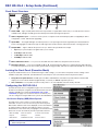
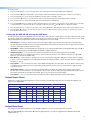
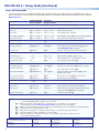
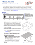
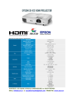
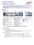
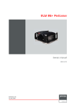
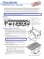
DSC HD-3G A Scaler • Setup Guide The Extron DSC HD-3G A is an HDMI to 3G-SDI scaler that converts HDMI signals to 3G-SDI, HD-SDI, and SD-SDI. It accepts computer and SMPTE video resolutions up to 1920x1200 and 2k, and offers multiple output rates from 480i up to HDTV 1080p @ 60 Hz and 2k. The DSC HD-3G A features advanced Extron video signal processing with 1080i deinterlacing and Deep Color processing for optimal image quality. Dual SDI outputs, stereo audio embedding, and genlock are also provided. This setup guide provides step-by-step instructions for an experienced user to set up and configure a DSC HD-3G A. It covers how to perform basic operations using the front panel controls and selected Simple Instruction Set (SIS™) commands. NOTE: For full installation, configuration, menus, connector wiring, and operation details, see the DSC 3G-HD A and DSC HD-3G A User Guide, available at www.extron.com. Installation a AC power connector b 5-pole captive screw audio input Rear Panel Features connector DSC HD-3G A 100-240V ~ .3A MAX INPUT AUDIO L HDMI SYNC GENLOCK OUTPUT 3G/HD/SD-SDI R REMOTE RS-232 Tx Rx G 50-60 Hz c HDMI video input connector d Genlock sync connectors e 3G/HD/SD-HDI output connectors f 3-pole RS-232 captive screw connector 1 2 3 4 5 6 Mounting and Cabling the DSC HD-3G A 1. Disconnect power: Turn off or disconnect all equipment power sources. 2. Mount the unit: (Optional) Mount the DSC HD-3G A either in a rack using shelf mounting brackets (RSU 129 or RSB 129) or under furniture using furniture mounting brackets (MBU 125) (see figures 1 and 2 at right). A false face plate (RFF 052) can be fitted on top of the low profile DSC if desired. 3. Connect the input: Connect an HDMI video source to the HDMI input connector c. Half-rack false front panel uses 2 front holes. 4. Connect analog audio input: (Optional) Connect analog audio from the source to the captive screw Audio input connector b. NOTE: To embed audio from this input, you must first set it up using the on-screen display (OSD) (see page 2) or SIS commands (see page 4). (2) 4-40 x 3/16" screws DI GI TA DV C L VID EO 50 CO 1S NV D ER TE R Use 2 mounting holes on opposite corners. Figure 1. Rack Mounting 5. Connect the output: Connect one or two SDI display devices to the 3G/HD/SD-SDI output connectors e for SDI output with optional embedded analog or HDMI audio. 6. Connect a control device: For remote control via SIS commands or the PCS Windows®-based control software: zz RS-232 — For serial RS-232 control, connect a host computer or control system to the 3-pole captive screw RS-232 connector f. RS-232 protocol (default values) are 9600 baud, 1 stop bit, no parity, 8 data bits, no flow control. zz USB — Connect a host computer or control system to the front panel mini USB port (b in the front panel illustration on page 2) for configuration and control via Extron PCS Control software. 7. AC power connector — Connect the supplied US standard IEC power cord between this connector a and a 110-220 V 50-60 Hz AC power source. Mounting Screws (2) Places Each Side #8 Screw (4) Places Each Side MBU 125 Mounting Bracket Figure 2. Under-furniture Mounting 1 DSC HD-3G A • Setup Guide (Continued) Front Panel Overview Extron INPUT CONFIG 1 2 OUTPUT SIGNAL SYNC 2CH-LPCM 2.97 Gbps MULTI-CH PCM 1.485 Gbps ANALOG 270 Mbps 3 4 DSC HD-3G A MENU AUTOIMAGE ENTER HOLD 5 FOR 720p 1080i 6 a Status LED — Lights steadily amber when there is power but no signal, blinks amber every 3 seconds when the unit is in standby mode, and lights steadily green when both power and an input signal are present. b USB configuration port — Connect a control system or computer to this mini USB port (cable not supplied) for device configuration, control, and firmware upgrading. c Input LEDs — The Signal LED lights to indicate presence of an input signal. An audio signal LED (2CH-LPCM, Multi-CH PCM, or Analog) lights to indicate the type of audio signal (two-channel LPCM, multi-channel PCM, or analog) if present. d Output LEDs — Light to indicate the presence of sync and the rate specified for the output: zz Sync: Sync is present (does not light if video sync is muted). zz 2.97 Gbps: SMPTE 424M zz 1.485 Gbps: SMPTE 292M zz 270 Mbps: SMPTE 259M e Menu and Enter buttons — Let you access the OSD and select submenus and options from the menus. f Navigation buttons — Press these right , left , up , and down arrow buttons to step through the OSD submenus, to lock the front panel (see the next section), perform Auto-Image (press ), and reset the output rate (hold for 5 seconds). Locking the Front Panel (Executive Mode) To prevent unauthorized access or accidental changes to DSC settings, you can lock the front panel controls, making control available only by SIS commands. (The default state is unlocked.) You can lock and unlock the front panel as follows: zz zz Using the front panel buttons: To lock, press the Menu and buttons simultaneously and hold them until the OSD displays Executive Mode Enabled (approximately 5 seconds). To unlock, repeat this process. SIS commands: To lock (enable executive mode), enter 1X. To unlock (disable executive mode), enter 0X. Configuring the DSC HD-3G A The DSC HD-3G A can be configured through a host connected to the RS-232 or USB port, using Extron PCS Windows-based control software (available at no charge at www.extron.com) or SIS commands (see page 4 for a selection of basic commands). You can also configure it using the OSD menu system, described below. On-Screen Display (OSD) Menu System The OSD menu system consists of seven submenus and two information screens. To access the menus, press the front panel Menu button. With the main menu displayed, use the arrow buttons to step through the submenus and submenu options. Press the Enter button to select items that you highlight. Communication and Device Info screens are read-only and do not provide selections. • Quick Setup • User Presets • Picture Controls • Input • Output • Audio • Advanced • Communication • Device Info. NOTE: The OSD times out and closes after 1 minute if no buttons are pressed. 2 To use any menu: 1. Press the Menu button to access the main menu. The menu opens with the Quick Setup menu displayed. 2. Press the and buttons repeatedly to cycle through to the desired submenu (each button press outlines the next option). 3. Press the Enter button to access the desired submenu. The first option is outlined in yellow. 4. Press the and buttons to cycle through the options of the selected submenu until the desired item is outlined. 5. Press the Enter button to select the outlined option (the selected option is highlighted). 6. Press the and buttons to adjust the values within the option. For the options on the Picture Controls submenu, press the right or left arrow button to select the sub-option on the right or left, then press the and buttons to adjust the settings. 7. Press the Enter button to confirm your new values. The yellow highlighting is replaced by the yellow outline on the submenu screen. to move to another submenu option or press the Menu button to exit the submenu. To exit the menu system, press the Menu button twice. 8. Press the or Setting Up the DSC HD-3G A Using the OSD Menu The Quick Setup submenu is displayed when the OSD opens. This submenu contains options from other submenus that you are most likely to need when configuring the DSC for the first time. Use the Quick Setup submenu to perform a basic system setup and get started quickly using the DSC. Select the following options from it as needed: zz Auto-Image™ — Performs an Auto-Image on the video input to adjust the horizontal and vertical size and positioning to the selected aspect ratio (fill the screen or follow the input device aspect ratio). To perform an Auto-Image, select this option, then press Enter again to initiate the Auto-Image. zz Input EDID — Matches the input EDID to the output rate or sets a discrete EDID. After selecting Input EDID, press the or button to step through the available EDIDs (the default is 720p @ 59.94 Hz). zz Output Resolution — Lets you select the resolution and refresh rate for the current output from 42 available factory-installed rates (see "Output Scaler Rates"). Select the Output Resolution submenu, then press the and buttons to cycle through the available rates. zz Auto Memory — Sets the DSC to automatically save the current input configuration and picture control values according to the most recent configuration for each different rate. After selecting Auto Memory, press any arrow button to toggle Auto Memories on and off. zz Aspect Ratio — Lets you specify how much of the display the image fills. The sub-options are Fill (fills the entire screen) or Follow (uses the aspect ratio of the input). After selecting Aspect Ratio, press any arrow button to toggle between Fill and Follow. zz Input Audio Format — Lets you select the format of the audio to embed in the output. After selecting Input Audio Format, press any arrow button to cycle through the options: None (mute the audio), Analog (embed analog audio onto the SDI output), LPCM-2CH (use the first channel pair), Multi-Ch (use the first four channel pairs). zz Test Pattern — Lets you select from seven test patterns to aid in setting up the DSC and the output display. Output Scaler Rates Output rates can be set using the OSD menu or SIS commands. The table below gives the rates and their SIS variables (see page 4 for the commands). SIS Variables for DSC HD-3G A Resolutions and Refresh Rates (X2) = 65 through 96) Resolution 23.98 Hz 24 Hz 25 Hz 29.97 Hz 30 Hz 50 Hz 480i 576i 720p 59.94 Hz 60 Hz 65 66 72* 73 67 95 96 68 69 70 71 74 75 76 1080p 77 78 79 80 81 82 83 84 2048x1080 (2k) 85 86 87 88 89 90 91 92 1080i *Default output resolution Output Rate Reset If an image cannot be displayed due to an incompatible output rate, you can reset the output rate as follows: With the OSD closed, press and hold the button for approximately 5 seconds to toggle between 1080i @ 59.94 Hz and 720p @ 59.94 Hz. 3 DSC HD-3G A • Setup Guide (Continued) Basic SIS Commands The DSC HD-3G A can be configured with specific SIS commands via RS-232 or USB connection. This table lists a selection of basic commands. For a full list of SIS commands and variables see the DSC HD-3G A and DSC HD-3G A User Guide, online at www.extron.com. Command ASCII Command (host to Scaler) Response (Scaler to Host) Additional Description View input video format 1*\ Vtype 1 * X# ] View detected input video format X#. Audio Input Format — select between analog (5-pole captive screw connector) and digital (embedded in HDMI input) audio sources. Set to none E I 1 * 0 AFMT } Afmt I 1 * 0 ] Mute all audio for the input. Set to analog E I 1 * 1 AFMT } Afmt I 1 * 1 ] Select analog audio for the input. Set to LPCM-2CH digital E I 1 * 2 AFMT } Afmt I 1 * 2 ] Select LPCM 2-channel digital audio for the input (default). Set to Multi-CH digital E I 1 * 3 AFMT } Afmt I 1 * 3 ] Select multi-channel digital audio for the input. Execute Auto-Image A Img ] Perform an Auto-Image on the current input. Set output scaler rate E X2) RATE } RATE X2) ] Select output resolution and refresh rate X2) (see the output SIS variables table on page 3). View output rate E RATE } X2) ] Show the current output rate for the DSC HD-3G A. Output Configuration Video Mute (Defaults to unmuted after a power cycle.) Mute video to black 1 * 1B Vmt 1 * 1 ] Mute the video and display a black screen. Mute video and output sync 1 * 2B Vmt 1 * 2 ] Mute all TMDS signals on the HDMI video output. View video mute status 1B X4@ ] View output video mute status (X4@). Screen Saver Mode (Takes place when no signal is detected on the input.) Set screen saver mode E M X4) SSAV } Ssav M X4) ] Set the screen saver mode to X4) (default = 1 = black). View screen saver mode E M SSAV } X4) ] View current screen saver mode X4). Set sync timeout duration E T X2* SSAV } Ssav T X2* ] Set the period before sync timeout to X2* seconds (default = 501 = never). View sync timeout duration E T SSAV } X2* ] View the amount of time X2* before sync timeout. View screen saver status E S SSAV } X6# ] View the screen saver status X6#. Reset device to factory settings E ZXXX } Zpx ] Resets all device settings to the factory defaults. Power save off E 0 PSAV } Psav 0 ] Set the DSC to run in full power mode (default). Power save on E 1 PSAV } Psav 1 ] Place the DSC in low power mode). (This mode can be exited only via the E 0 PSAV } command View power save setting E PSAV } X6@ ] View power save status X6@. Power Save Mode NOTE: X# = Input video format: 0 = no signal; 1 = HDMI, 2 = DVI, 3 = invalid signal (up to 30 Hz); 4 = 3G-SDI 1080p (@ 50, 59.94, and 60 Hz), 2k; 5 = unknown. X2) = Output scaler rate: 0 = match output rate, 1 = custom rate 1, 2 = custom rate 2, 3 = custom rate 3, 9 = match input (see the resolution and refresh rate table on page 3 for more rate variables). X2* = Output sync timeout duration in seconds (1-500 in 1-second increments): 501 = never (default), 0 = immediate timeout X4) = Screen saver mode: 1 = black (default), 2 = blue X4@ = Video mute: 0 = off (unmute), 1 = on (mute to black screen), 2 = on (mute all output sync and video) X6@ = Power save setting: 0 = full power (default), 1 = low power state X6# = Screen saver status: 0 = active, timer not running; 1 = no active input, timer running, output sync active; 2 = No active input, timer expired Extron Headquarters +1.800.633.9876 (Inside USA/Canada Only) Extron Asia +65.6383.4400 Extron China +86.21.3760.1568 Extron Korea +82.2.3444.1571 Extron Europe +31.33.453.4040 Extron Japan +81.3.3511.7655 Extron Middle East +971.4.2991800 Extron India +91.80.3055.3777 © 2013 Extron Electronics — All rights reserved. All trademarks mentioned are the property of their respective owners. www.extron.com 4 68-2261-50 Rev. A 10 13