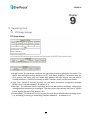
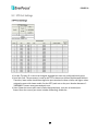
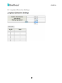
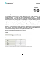
1
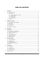
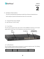
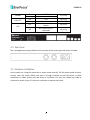
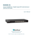
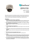
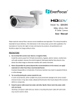
ES1625-31 16-port 10/100M PoE + 2 Gigabit Copper/SFP Combo Rackmount Web Smart PoE Switch User’s Manual Copyright © EverFocus Electronics Corp, Release Date: September, 2013 Notice: This content is subject to be changed without notice. EVERFOCUS ELECTRONICS CORPORATION ES1625-31 User’s Manual 2013 EverFocus Electronics Corp www.everfocus.com All rights reserved. No part of the contents of this manual may be reproduced or transmitted in any form or by any means without written permission of the Everfocus Electronics Corporation. Release Date: September, 2013 QuickTime is a registered trademark of the Apple Computer, Inc. Windows is a registered trademark of the Microsoft Corporation. Linksys is a registered trademark of the Linksys Corporation. D-Link is a registered trademark of the D-Link Corporation. DynDNS is a registered trademark of the DynDNS.org Corporation. Other product and company names mentioned herein may be the trademarks of their respective owners. Safety Precautions FCC Warning This Equipment has been tested and found to comply with the limits for a Class-A digital device, pursuant to Part 15 of the FCC rules. These limits are designed to provide reasonable protection against harmful interference in a residential installation. This equipment generates, uses, and can radiate radio frequency energy. It may cause harmful interference to radio communications if the equipment is not installed and used in accordance with the instructions. However, there is no guarantee that interference will not occur in a particular installation. If this equipment does cause harmful interference to radio or television reception, which can be determined by turning the equipment off and on, the user is encouraged to try to correct the interference by one or more of the following measures: Reorient or relocate the receiving antenna. Increase the separation between the equipment and receiver. Connect the equipment into an outlet on a circuit different from that to which the receiver is connected. Consult the dealer or an experienced radio/TV technician for help. CE Mark Warning This is a Class-A product. In a domestic environment this product may cause radio interference in which case the user may be required to take adequate measures. ii TABLE OF CONTENTS 1. Introduction.................................................................................................................. 1 1.1 Product Overview .......................................................................................................... 1 1.2 Key Features................................................................................................................... 1 1.2.1 Web Management Features ............................................................................... 1 1.2.2 Specifications ...................................................................................................... 2 1.2.3 Mechanical .......................................................................................................... 2 1.2.4 Performance........................................................................................................ 3 1.3 Package .......................................................................................................................... 3 2. Hardware Description ................................................................................................... 4 2.1 2.2 2.3 2.4 2.5 Physical Dimensions/ Weight ........................................................................................ 4 Front Panel ..................................................................................................................... 4 LED Indicators ................................................................................................................ 4 Rear Panel ...................................................................................................................... 5 Hardware Installation .................................................................................................... 5 3. User Log In .................................................................................................................... 6 4. Administrator ............................................................................................................... 8 4.1 4.2 4.3 4.4 4.5 4.6 5. Port Management ....................................................................................................... 12 5.1 5.2 5.3 5.4 5.5 6. Authentication Configuration ........................................................................................ 8 System IP Configuration................................................................................................. 8 System Status ................................................................................................................. 9 Load Default Setting..................................................................................................... 10 Firmware Update ......................................................................................................... 10 Reboot Device .............................................................................................................. 11 Port Configuration ....................................................................................................... 12 Port Mirroring .............................................................................................................. 13 Bandwidth Control ....................................................................................................... 13 Broadcast Storm Control.............................................................................................. 14 PoE ............................................................................................................................... 15 VLAN Setting ............................................................................................................... 16 6.1 VLAN Mode .................................................................................................................. 16 6.2 VLAN Member .............................................................................................................. 17 6.3 Multi to 1 Setting ......................................................................................................... 19 7. Per Port Counter ......................................................................................................... 20 iii 7.1 7.2 7.3 7.4 8. Port Counter................................................................................................................. 20 QoS Setting................................................................................................................... 21 Priority Mode ............................................................................................................... 21 Port, 802.1p, IP/DS based ............................................................................................ 22 Security....................................................................................................................... 23 8.1 MAC Address Binding................................................................................................... 23 8.2 TCP/UDP Filter ............................................................................................................. 23 9. Spanning Tree ............................................................................................................. 24 9.1 STP Bridge Settings ...................................................................................................... 24 9.2 STP Port Settings .......................................................................................................... 25 9.3 Loopback Detection Settings ....................................................................................... 26 10. Trunking.................................................................................................................... 27 11. Backup /Recovery ..................................................................................................... 28 12. Miscellaneous ........................................................................................................... 29 13. Logout....................................................................................................................... 30 14. Specification ............................................................................................................. 31 iv ES1625-31 Chapter 1. 1 Introduction 1.1 Product Overview This switch provides 16 10/100Mbps RJ-45 ports and can support 2 Combo Gigabit RJ-45/SFP to uplink. This web-smart switch includes auto-MDI/MDIX crossover detection function. 16 of those ports are all built with PoE functionality, providing the ultimate choice in network flexibility. With this added PoE feature, this switch is an ideal solution for building wireless, IP surveillance, and VoIP networks. It also provides port-based and 802.1Q tag VLAN function to provide better traffic management, reduces latency, improve security and save bandwidth. This is also a cost-saving feature as it reduces the need to add additional hardware to the network. These 16 10/100Mbps RJ-45 support the IEEE 802.3at PoE protocol. Each port and transmit a maximum power 30 watts. User can also enable or disable power supply on PoE ports from UI.. 1.2 Key Features 1.2.1 Web Management Features • Port Management Port Configuration Port Mirroring Bandwidth Control Broadcast Strom Control PoE On/Off Setting • VLAN Setting Port-based/ Tag-based VLAN ID: 1~4094 • Trunking Link Aggregation Setting 2 groups (1~4 port for each group) • QoS Setting Priority Mode 1 ES1625-31 Class of Service Configuration TCP/UDP Port-based • Security Setting MAC address filtering TCP/UDP Port filtering • STP/RSTP • Spanning Tree Protocol • Backup Recovery Configuration 1.2.2 Specifications • Standard IEEE 802.3 10BaseT IEEE 802.3u 100BaseTX IEEE 802.3x Full-duplex and Flow Control IEEE 802.af PoE IEEE 802.at PoE IEEE 802.3ad Link Aggregation IEEE 802.1d Spanning tree protocol IEEE 802.1w Rapid Spanning tree protocol IEEE 802.1x Port-based Network Access Control IEEE 802.1Q VLAN IEEE 802.1p Class of Service • Number of Port 16-port 10/100BaseTX with PoE 2-port Combo Gigabit uplink (RJ-45/SFP) 1.2.3 Mechanical • LED Indicator Per Port: Link/ Act PoE Port: Act/Status Per Unit: Power • Power Consumption: 250Watts (Max) • Power Input: 100~240V/AC, 50~60HZ • Power Output: 48V/DC per Port Output – 30W Max per Port • Product Dimensions/ Weight 2 ES1625-31 45 × 440 × 330 mm (H × W ×D) / 4.4kg 1.2.4 Performance • MAC Address: 4K • Buffer Memory: 2.75Mb • Transmission Method: Store and Forward 1.3 Package Before you start to install this switch, please verify your package that contains the following items: 1. One Fast Ethernet PoE Switch 2. One EU Power Cord 3. A User Manual CD 4. Rack-mount kit 3 ES1625-31 Chapter 2 2. Hardware Description This section mainly describes the hardware of the 8 PoE port Ethernet Combo Web-Smart Switch and gives a physical and functional overview on the certain switch. 2.1 Physical Dimensions/ Weight 45 × 440 × 330 mm (H × W ×D) / 4.4kg 2.2 Front Panel The front panel of the web smart switch consists of 16 10/100Base-TX RJ-45 ports and 2 combo gigabit uplink RJ-45/SFP ports. The LED Indicators are also located on the front panel. LED Display RJ-45 Port Combo Uplink RJ-45/SFP Port 2.3 LED Indicators The LED Indicators present real-time information of systematic operation status. The following table provides description of LED status and their meaning. LED Power Status On Description Power on 4 No. Of LED Power ES1625-31 1000M Link/ ACT On off On Flashing On PoE Off Link 1000Mbps Link 10/100Mbps Link Data activating Port is linked to Power Device No Power Device is connected 2 (17~18) 18 (1~18) 18 (1~18) 16 (1~16) 16 (1~16) 2.4 Rear Panel The 3-pronged power plug is placed at the rear panel of the switch right side shown as below. 2.5 Hardware Installation Set the switch on a large flat space with a power socket close by. The flat space should be clean, smooth, level and sturdy. Make sure there is enough clearance around the switch to allow attachment of cables, power cord and allow air circulation. The last, use twisted pair cable to connect this switch to your PC then user could start to operate the switch 5 ES1625-31 Chapter 3 3. User Log In This part instructs user how to set up and manage the switch through the web user interface. Please follow the description to understand the procedure. At the first, open the web browser, and go to 192.168.2.1 site then the user will see the login screen. Key in the password to pass the authentication then clicks the OK. The log in process is completed and comes out the sign “Password successfully entered”. Log in ID: admin Password: admin ※Note: It will show error message if you key in wrong user name or password. 6 ES1625-31 Main Page 7 ES1625-31 Chapter 4 4. Administrator 4.1 Authentication Configuration This page shows authentication configuration information. User can set new Username and Password in this page. 4.2 System IP Configuration This page shows system configuration including the current IP address and sub-net mask and gateway. 8 ES1625-31 User can configure the IP settings, Subnet Mask, Gateway as below: IP address: Manually assign the IP address that the network is using. The default IP is 192.168.2.1 Subnet Mask: Assign the subnet mask to the IP address. Gateway: Assign the network gateway for industrial switch. If you change the IP address of this switch and then press Update. It will show “update successfully” then press Reboot button. It will enter user login screen automatically. 4.3 System Status This page displays the information about the switch of MAC address, how many ports it has, system version and. Besides, users can also fill in up to 15 characters in the Comment, Contact and Location field for note. MAC Address: Displays the unique hardware address assigned by manufacturer (default). Number of Ports: Displays number of ports in the switch. System Version: Displays the switch’s firmware version. Idle Time Security: User can set the time security. When user leave the computer for a moment, the software will auto logout or back to the last display. And then click Update button. 9 ES1625-31 4.4 Load Default Setting Clicking the Load button will make the switch being set to the original configuration. ※ Note: It exclude to change user name, password and IP configuration. If you want to restore default setting including IP and user name password, then you can press the reset button for hardware base reset. More detail information about Load Default Setting - Hardware Base is described as following. The purpose of this function is to provide a method for the network administrator to restore all configurations to the default value. (1) To activate this function, the user should follow the following procedures. Press the “Load default” button for 3 seconds until you see the LED blinking. (2) When LED starts blinking, it means the CPU is executing the “load default” procedure. You can release the button now. After completing this procedure, all the factory default value will be restored. It includes the IP address, the user name, the password and all switch configurations. 4.5 Firmware Update Before the firmware update procedure is executed, you should enter the password twice and then press Update button. The smart switch will erase the flash memory. There is a self-protection mechanism in the Boot Loader, so the Boot Loader will keep intact. Even though the power is turned off or the cable link fails during the firmware update procedure, the Boot loader will restore the code to firmware update page. 10 ES1625-31 After pressing Update button, the old web code will be erased. Then you can select the image file and press “update” button to update the firmware you need. 4.6 Reboot Device Click Confirm button to reboot the device. ※Note: The reboot is for software base instead of hardware base. 11 ES1625-31 Chapter 5 5. Port Management Port Management includes Port Configuration, Port Mirroring, Bandwidth Control, Broadcast Storm Control and PoE. 5.1 Port Configuration In Port Configuration, you can set and view the operation mode for each port. Auto-Negotiation: Enable and Disable. Being set as ‘Enable’, the Speed, Duplex mode, Pause, Backpressure, TX Capability and Address Learning are negotiated automatically. When you set it as ‘Disable’, you have to assign those items manually. Speed: When the Auto-Negotiation column is set as Disable, users have to set the connection speed to the ports ticked. Duplex: When the Auto-Negotiation column is set as Disable, users have to set the connection mode in Half/Full to the ports ticked. Pause: Flow Control for connection at speed of 10/100Mbps in Full-duplex mode. Backpressure: Flow Control for connection at speed of 10/100Mbps in Half-duplex mode. TX/RX Capability: When the Auto-Negotiation column is set as Disable, users have to set this column as Enable or Disable. Addr. Learning: When the Auto-Negotiation column is set as Disable, users have to set this column as Enable or Disable. Select Port No.: Tick the check boxes beside the port numbers being set. Click Update to have the configuration take effect. 12 ES1625-31 Current Status: Displays current port status. Setting Status: Displays current status. Click Update to make the configuration effective. 5.2 Port Mirroring The Port mirroring is a method for monitoring traffic in switched networks. That Traffic through ports can be monitored by any of the ports means traffic goes in or out monitored (source) ports will be duplicated into mirroring (destination) port. Destination (mirroring) port for monitoring Rx only, Tx only or both RX and TX traffic which come from the source port. Users can connect the mirroring port to LAN analyzer or Netxray. Monitored Packets: Pull down the selection menu to choose what kind of packet is to be monitored. Source Port: The ports that the user wants to monitor. All monitored port traffic will be copied to mirroring (destination) port. Users can select multiple source ports by ticking the check boxes beneath the port number label to be monitored. And then, click Update to have the configuration take effect. 5.3 Bandwidth Control This page allows the setting of the bandwidth for each port. The TX rate and Rx rate can be filled with the number ranging from 1 to 255. This number should be multiplied by the selected bandwidth resolution to get the actual bandwidth. 13 ES1625-31 5.4 Broadcast Storm Control The switch implements a broadcast storm control mechanism. Tick the check boxes to have them beginning to drop incoming broadcast packets if the received broadcast packet counts reach the threshold defined. Each port’s broadcast storm protection function can be enabled individually by ticking the check boxes. The broadcast packet is only checked at the selected port and the number of broadcast packets is counted in every time unit. One time unit is 500 us for 10Mbps speed and 5ms for 100Mbps. The excessive broadcast packet will be discarded. For those broadcast packets incoming from the un-selected port, the switch treats it as the normal traffic. Threshold: Type in the threshold in the range between 1 and 63 to limit the maximum byte counts, which a port can send or receive in a period of time. Enable Port: Having ticked the boxes, the port will stop transmitting or receiving data when their sending byte counts or receiving byte counts reach the defined threshold. Click Update to have the configuration take effect. 14 ES1625-31 5.5 PoE User could know per PoE port out power status in this page and also enable or disable per port. 15 ES1625-31 Chapter 6 6. VLAN Setting A Virtual LAN (VLAN) is a logical network grouping that limits the broadcast domain, which would allow you to isolate network traffic, so only the members of the same VLAN will receive traffic from the ones of the same VLAN. Basically, creating a VLAN from a switch is logically equivalent of reconnecting a group of network devices to another Layer 2 switch. However, all the network devices are still plugged into the same switch physically. 6.1 VLAN Mode You may select the VLAN Mode of the switch. Port-based VLAN is for separating traffic only on this single switch. There is no handover of network traffic within VLAN groups to other switches. For the handover to other switches use Tag Based VLAN. In VLAN Mode you can switch from Tag to Port Based VLAN. Port Based VLAN is the default mode. After having switched to Tag Based VLAN Mode, the screen changes. On this screen you can now define and configure your Up- and Downlink ports. These are important since here the handover between the switches of your network takes place. VLAN Mode: Displays VLAN mode: port based/Tag based VLAN. Here you can also switch back to Port Based VLAN Mode Add tag means the outgoing packet of the selected port will be inserted a 802.1Q tag. Use this 16 ES1625-31 setting for your Up- and Downlink Ports in your VLAN Tagged Network. Don’t care means the outgoing packet of the selected port keep the original packet received at the source port. This is the default setting when starting VLAN configuration. You should change to either Add or Remove Tag. Remove tag means the 802.1Q tag of the outgoing packet of the selected port will not be sent. Use this setting for your Network Connections to PCs. Only packets of the VLAN Group the Port is member of will be sent. 6.2 VLAN Member The ports need to be made member of your VLAN groups. This is for Tag Based and Port Based VLAN Mode. The screen here looks different whether you run Tag Based or Port Based Mode. VLAN Member in Port Based Mode In Port Based Mode you see a matrix of your 8 Ports. Simply select the port on top screen you want to configure, click on Read, and then select or deselect the ports that are on the same VLAN group. In this configuration mode you do not need to worry about defining VLAN groups and VLAN IDs. VLAN Member in Tag Based Mode In Tag Based Mode you need to define and configure your VLAN groups. Since you want the handover to other switches take place smoothly, the VLAN IDs (Numbers) need to be like on the rest of your network. On other switches you may have the chance to configure names. These are just for your reference. Only the numbers are important! 17 ES1625-31 There firstly add your VLAN Groups (identified throughout your network by unique and constant numbers). Start with IDs from 100 and up. Keep in mind that some switches use “1” as the default, while others use “4095” or “4096” as default. Starting with 100 gives you enough free room and less compatibility issues. So enter “100” in the field right of VID Setting, then select or deselect which ports are member of that group. Your up- and downlink ports need to member of every existing group! Then click on add. The new group with its setting will be displayed at the bottom of the screen. With the PVID Setting you define to which VLAN group incoming traffic belongs. Consider the example that Port 1 is member of group 100 and 101. A simple PC is connected to Port 1. If that PC is now sending out data, with PVID you define if that data is for group 100 or 101. 18 ES1625-31 6.3 Multi to 1 Setting Multi to 1 VLAN is used in CPE side of Ethernet-to-the-Home and is exclusive to VLAN setting on VLAN Member Setting. When VLAN member Setting is updated, multi to 1 setting will be void and vice versa. The disable port means the port which will be excluded in this setting. All ports excluded in this setting are treated as the same VLAN group. In a normal Tag Based VLAN network you will not need this configuration option. 19 ES1625-31 Chapter 7. 7 Per Port Counter 7.1 Port Counter This page provides port counter of each port. There are 4 categories: Receive Packet & Transmit Packet/ Transmit & Collision / Receive Packet & Drop /Receive & CRC error. Once you change the counter category, the counter will be cleared automatically. Transmit packet & Receive packet: This category shows both the received packet count (excluding the incorrect packet) and the transmitted packet count. Collision Count & Transmit packet: This category shows the packets outgoing from the switch and the count of collision. Drop packet & Receive packet: This category shows the number of received valid packet and the number of dropped packet. CRC packet & Receive packet: This category shows the received correct packet and received CRC error. Clear: Press “clear” will clear all counters. Refresh: Press “Refresh” button will aggregate the number of the counter for all ports. 20 ES1625-31 7.2 QoS Setting Here you can configure QoS policy priority mode and CoS (Class of Service) configuration. QoS (Quality of Service) refers to mechanisms in the network software that make the actual determination of which packets have priority. CoS refers to feature sets, or groups of services, that are assigned to users based on company policy. If a feature set includes priority transmission, then CoS winds up being implemented in QoS functions within the routers and switches in the network. In an enterprise network, class of service (CoS) differentiates high-priority traffic from lower-priority traffic. Tags may be added to the packets to identify such classes, but they do not guarantee delivery as do quality of service (QoS) functions, which are implemented in the network devices. 7.3 Priority Mode There are three priority modes available to specify the priority of packets being serviced. Those include First-In-First-Out, All-High-Before-Low, and Weight-Round-Robin. First-In-First-Out: Packets are placed into the queue and serviced in the order they were received. All-high-before-low(Strict priority):All packets will be assigned to either high priority queue (Queue 2) or low priority queue (Queue 1). The packet on the low priority queue will not be forwarded until the high priority queue is empty. WRR mode: There are 4 priority queues for Weighted-and-round-robin (WRR) mode. When this mode is selected, the traffic will be forwarded according to the number set in each queue. 21 ES1625-31 7.4 Port, 802.1p, IP/DS based TCP/UDP Port Based 22 ES1625-31 Chapter 8 8. Security 8.1 MAC Address Binding Port No: Displays the port number being assigned the MAC addresses. MAC Address: Users can assign up to 3 MAC addresses to the port. Read: Pull down the selection bar to choose a port number and click the read button to show the MAC addresses bound with the port or modify the MAC addresses. Select Port: Pull down the selection menu bar to choose a port number to be set. Binding: Enable or disable the binding function. Click Update to have the configuration take effect. 8.2 TCP/UDP Filter 23 ES1625-31 Chapter 9 9. Spanning Tree 9.1 STP Bridge Settings Bridge Priority: This parameter configures the spanning tree priority globally for this switch. The device with the highest priority becomes the STP root device. However, if all devices have the same priority, the device with the lowest MAC address will then become the root device. Number between 0 - 61440 in increments of 4096. Therefore, there are 16 distinct values. Hello Time: Interval (in seconds) at which the root device transmits a configuration message (BPDU frame). Number between 1-10 (default is 2). Max Age – The maximum time (in seconds) a device can wait without receiving a configuration message before attempting to reconfigure. That also means the maximum life time for a BPDU frame. Number between 6-40 (default is 20). Forward Delay: The maximum time (in seconds) the root device will wait before changing states (i.e., discarding to learning to forwarding). Number between 4 – 30 (default is 15). 24 ES1625-31 9.2 STP Port Settings Port No: The port ID. It cannot be changed. Aggregations mean any configured trunk group. Root Path Cost: This parameter is used by the STP to determine the best path between devices. Therefore, lower values should be assigned to ports attached to faster media, and higher values assigned to ports with slower media. Set the RSTP path cost on the port. Number between 0 200000000. 0 means auto generated path cost. State: Show the current port state includes designated port, root port or blocked port. Status: Show the current port status includes forwarding, disable etc… 25 ES1625-31 9.3 Loopback Detection Settings 26 ES1625-31 Chapter 10 10. Trunking Port trunk allows multiple links to be bundled together and act as a single physical link for increased throughput. It provides load balancing, and redundancy of links in a switched inter-network. Actually, the link does not have an inherent total bandwidth equal to the sum of its component physical links. Traffic in a trunk is distributed across an individual link within the trunk in a deterministic method that called a hash algorithm. The hash algorithm automatically applies load balancing to the ports in the trunk. A port failure within the trunk group causes the network traffic to be directed to the remaining ports. Load balancing is maintained whenever a link in a trunk is lost or returned to service. This switch may use Port ID, Source MAC Address, Destination MAC Address, or a combination of Source MAC Address and Destination MAC Address to be the selection for Trunk Hash Algorithm. Traffic pattern on the network should be considered carefully before applying it. When a proper hash algorithm is used, traffic is kind of randomly decided to be transmitted across either link within the trunk and load balancing will be seen. This managed switch supports two trunk group, each trunk consists of 2~4 ports. Trunk hash algorithm can be selected according to 4 different methods. 27 ES1625-31 Chapter 11 11. Backup /Recovery This function provides the user with a method to backup/recovery the switch configuration. The user can save configuration file to a specified file. If the user wants to recover the original configuration, which is saved at the specified path, just enter the password and then press the “upload” button. Finally the original configuration of the switch will be recovered. 28 ES1625-31 Chapter 12 12. Miscellaneous Miscellaneous setting is used to configure output queue aging time, VLAN stride and IGMP snooping. Output queue aging: This function is used to avoid the poor utilization of the switch. When a packet is stored in a switch for a long time, it will expire from the allowable time defined by the protocol and become a useless packet. To prevent these packets from wasting the bandwidth, this switch provide an option for the administrator to enable the queue aging function. VLAN Striding: By selecting this function, the switch will forward uni-cast packets to the destination port, no matter whether destination port is in the same VLAN. IGMP Snooping: When this function is enabled, the switch will execute IGMP snooping version 1 and version 2 without the intervention of CPU. The IGMP report and leave packets are automatically handled by the switch. 29 ES1625-31 Chapter 13 13. Logout The administrator has write access for all parameters governing the onboard agent. User should therefore assign a new administrator password as soon as possible, and store it in a safe place. When you forgot your IP or password, please use the reset button for the factory default setting? Please take the following steps to reset the Web Smart Switch back to the original default: Step 1: Turn on the Web Smart Switch Step 2: Press and hold the reset button continuously for 5 seconds and release the reset button. Step 3: The switch will reboot for 20 seconds and the configuration of switch will back to the default setting. Key in the user ID and the password to pass the authentication; the user ID and the password are “admin” IP: 192.168.2.1 ID: admin Password: admin 30 ES1625-31 Chapter 14 14. Specification Model Name Standards Features Smart Features ES1325-31 Ethernet: IEEE 802.3 10BaseT, IEEE 802.3u 100BaseTX, IEEE 802.ab 1000BaseT, IEEE 802.3z 1000BaseSX/LX IEEE 802.3x Flow Control IEEE 802.3ad Link Aggregation Control Protocol IEEE 802.1Q VLAN IEEE 802.1p Class of Service IEEE 802.1D Spanning Tree Protocol IEEE 802.1w Rapid Spanning Tree Protocol IEEE 802.3at Power Over Ethernet (PoE+) Number of Ports: 18 10/100BaseTX with RJ-45 Connectors: 16 port with PoE+ Gigabit Uplink: 2x 10/100/1000BaseT RJ-45 / Gigabit SFP Combo Port MAC Address: 4K Buffer Memory: 2.75Mb Transmission Method: Store and Forward Port Based VLAN: 18 Tagged Based VLAN: 32, VID = 1~4094 STP/RSTP IGMP Snooping V1&V2 Link Aggregation: 1, Gigabit Ports Quality of Service(QoS): High & Low queues, 802.1p Security: Port & MAC binding, 3 MAC per port Port: Port State, Speed/Duplex, Flow Control Port Mirroring Bandwidth Control Broadcast Storm Control PoE Control: PoE Port Enable/Disable, PoE Status 31 ES1625-31 Filtering/Forwarding Rates Transmission Media LED Indicators Power Input Power Output Power Consumption Dimensions Operating Temperature Storage Temperature Humidity Certifications Weight Management: Web Management, password protected access, Configuration backup/restore, TFTP firmware upgrade 1000Mbps port – 1,488,000pps 100Mbps port - 148,800pps, 10Mbps port - 14,880pps 10/100BaseTX Cat. 5 UTP/STP 1000BaseT Cat. 5 / Cat. 5E UTP/STP Per Port: Link/Act, PoE : Act / Status, Per Unit: Power 100~240 V/AC, 50~60Hz 53V DC Per Port Output 250 Watts 44 × 440 × 332 mm (H x W x D) 0 to 40 ℃ -20 to 90 ℃ 10 to 90% RH (non-condensing) FCC Class A, CE 4.2kg 32 EverFocus Electronics Corp. EverFocus Taiwan: 12F, No.79, Sec. 1, Shin-Tai Wu Road, Hsi-Chih, Taipei, Taiwan TEL: +886 2 2698 2334 FAX: +886 2 2698 2380 www.everfocus.com.tw [email protected] EverFocus Europe - Germany: Albert-Einstein-Strasse 1, D-46446 Emmerich, Germany TEL: +49 2822 93940 FAX: +49 2822 939495 www.everfocus.de [email protected] EverFocus China - Beijing: Room 609, Technology Trade Building, Shangdi Information Industry Base, Haidian District, Beijing 100085, China TEL: +86 10 6297 3336~39 FAX: +86 10 6297 1423 www.everfocus.com.cn [email protected] EverFocus China - Shenzhen: 4F, No. 2, D4 Building, Wan Yelong Industrial Park, Tangtou Road, Shiyan, Baoan, Shenzhen, Guangdong 518101, China TEL: +86 755 2765 1313 FAX: +86 755 2765 0337 www.everfocus.com.cn [email protected] EverFocus USA - California: 1801 Highland Avenue, Unit A, Duarte, CA 91010, USA TEL: +1 626 844 8888 FAX: +1 626 844 8838 www.everfocus.com [email protected] EverFocus USA - New York: 415 Oser Avenue, Unit S, Hauppauge, NY 11788, USA TEL: +1 631 436 5070 FAX: +1 631 436 5027 www.everfocus.com [email protected] EverFocus Japan: 5F, Kinshicho City Building, 2-13-4 Koto-Bashi,Sumida-Ku, Tokyo, 130-0022, Japan TEL: +81 3 5625 8188 FAX: +81 3 5625 8189 www.everfocus.co.jp [email protected] EverFocus Europe - UK: Unit 12, Spitfire Business Park, Hawker Road, Croydon Surrey, CR0 4WD, UK TEL: +44 20 8649 9757 / +44 845 430 9999 FAX: +44 20 8649 9907 www.everfocusuk.co.uk [email protected] EverFocus India: Suite 803, Housefin Bhavan, C-21, Bandra Kurla Complex, Bandra (East), Mumbai 400051, India TEL: +91 22 6128 8700 FAX: +91 22 6128 8705 www.everfocus.in [email protected] Your EverFocus product is designed and manufactured with high quality materials and components which can be recycled and reused. This symbol means that electrical and electronic equipment, at their end-of-life, should be disposed of separately from your household waste. Please, dispose of this equipment at your local community waste collection/recycling centre. In the European Union there are separate collection systems for used electrical and electronic product. Please, help us to conserve the environment we live in! Ihr EverFocus Produkt wurde entwickelt und hergestellt mit qualitativ hochwertigen Materialien und Komponenten, die recycelt und wieder verwendet werden können. Dieses Symbol bedeutet, dass elektrische und elektronische Geräte am Ende ihrer Nutzungsdauer vom Hausmüll getrennt entsorgt werden sollen. Bitte entsorgen Sie dieses Gerät bei Ihrer örtlichen kommunalen Sammelstelle oder im Recycling Centre. Helfen Sie uns bitte, die Umwelt zu erhalten, in der wir leben!