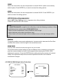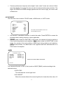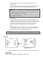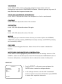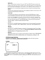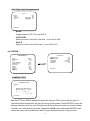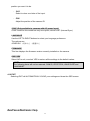
1
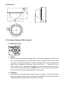
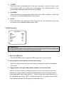
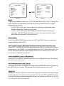
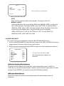
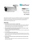
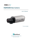
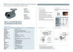
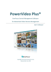
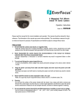
EVERFOCUS Model No. EHD630s 700TVL Super Low Light D-WDR & 3-Axis Gimbal Mechanism Vandal Proof & Weather Resistant Outdoor IR Dome Camera Operating Instructions Please read this manual first to ensure correct installation and operation. This manual should be retained for future reference. The information in this manual was current when published. The manufacturer reserves the right to revise and improve its products. All specifications are therefore subject to change without notice. PRECAUTIONS 1. Do not install the camera near electric or magnetic fields. Install the camera away from TV/radio transmitters, magnets, electric motors, transformers and audio speakers, because the electromagnetic fields generated by these devices may distort the video image or otherwise interfere with camera functions. 2. Never disassemble the camera beyond the recommendations in this manual, nor apply materials to it other than those recommended herein. Improper disassembly or introduction of corrosive materials may result in equipment failure or other damage. 3. Try to avoid pointing the camera toward the sun. In some circumstances, direct sunlight may cause permanent damage to the sensor and/or internal circuits. It may also create unbalanced illumination that may be beyond the camera’s ability to compensate. 4. Keep the power cable away from water and other liquids. Never touch the power cable with wet hands. Touching a wet power cable with your hands or touching the power cable with wet hands may result in electric shock. 5. Never install the camera in areas exposed to oil, gas or solvents. Oil, gas or solvents may cause equipment failure, electric shock or, in extreme cases, fire. 6. Cleaning For cameras with interchangeable lenses, do not touch the surface of the sensor directly with your hands. Use lens tissue or a cotton tipped applicator and ethanol to clean the sensor and the camera lens. Use a damp soft cloth to remove any dirt from the camera body. Do not use complex solvents, or corrosive or abrasive agents to clean any part of the camera. 7. Do not operate the camera beyond the specified temperature, humidity and power source levels. This camera is suitable for indoor operation only. Use the camera at temperatures between -10°C~50°C (14°F~122°F) and humidity levels between 20%~ 80%. This device is not rated as submersible. The input power source should be 12VDC or 24VAC. Be sure to connect the polarity (+ / -) and power properly. Incorrect polarity or too high a voltage will likely cause damage to the camera, and such damage is not covered by the warranty. The use of a properly fused or “Class 2 Limited Power Source” power supply is highly recommended. 8. Mounting Select a solid mounting surface that will support the weight of the camera and any additional loading from wind, snow, ice or other factors. Securely attach the camera to the mounting surface using screws and anchors that will properly support the camera. If necessary, (e.g. when mounting the camera to a drop ceiling, or unsupported ceiling) use a safety wire to provide additional support for the camera. 1. INTRODUCTION The EverFocus Polestar III-series EHD630s dome camera features amazing 700TVL color low light sensitivity of 0.03 lux, delivered by a 1/3” Sony EXview HAD CCD II 960H sensor. It also features the added benefits of advanced Effio-S DSP technology to enhance image quality. This camera also utilizes technologies like 3DNR (to reduce recording file sizes and thus conserve DVR HDD space), Digital Slow Shutter (to “see” in very low light by enabling super-high light sensitivity of up to 0.00006 lux), Digital Wide Dynamic Range, Day/Night mode switching, Digital Image Stabilizer, a 3-Axis gimbal mechanism, Privacy Masking, Motion Detection, 256x Digital Zoom, Mirroring, and much more! 1.1 FEATURES 700TVL superior image quality with Sony 1/3” EXview HAD CCD II 960H sensor. Starlight super-high sensitivity of 0.00006Lux/F=1.2 is achieved by Digital Slow Shutter (Sens-Up 512x). The Sony Effio-S platform performs advanced camera functions and delivers excellent picture quality. Varifocal DC Iris Lens 2.8~10mm. Supports 3D & 2D Noise Reduction. High sensitivity, low smear, high anti-blooming and high S/N ratio for high-performance video. 30 IR LEDs with a range of up to 15m (50ft) Easy-to-use OSD Setup Menu. D-WDR functions enabled by Sony Extended ATR technology handle tough backlight conditions. Built-in Back Light Compensation (BLC), High Light Compensation (HLC), Auto Electronic Shutter (AES), Auto Gain Control (AGC) and Auto White Balance (AWB). Digital Image Stabilization. Digital Zoom. Built-in Motion Detection and Privacy Mask advanced surveillance functions. 3-Axis Gimbal Mechanism enables flexible view perspective. Weather Resistant IP66, Vandal Proof for outdoor usage. 1 1.2 PACKAGE CONTENTS 1 x EHD630s Camera with pigtail 1 x EHD630s User Manual 1 x Accessory pack with screws 1 x Mounting template 1 x Lens-cleaning cloth 1.3 SPECIFICATIONS Pickup Device Video Format Picture Elements Horizontal Resolution Sensitivity S/N Ratio Video Output Gamma Correction Lens Type High Light Compensation Auto Electronic Shutter Auto Gain Control Auto White Balance Sync. Mode Day & Night Mode IR LED IR Configuration IR Wavelength IR Range OSD Menu DNR D-WDR(Extended ATR) Digital Slow Shutter Digital Image Stabiliz. Digital Zoom Mirror Motion Detection Privacy Mask Power Source Power Consumption Operating Temperature Dimensions (O.D.xH) Weight Certifications Accessory Options 1/3" Sony 960H EXview HAD CCD II NTSC PAL 1020(H)x508(V) 1020(H)x596(V) 700TVL 0.03Lux/F1.2; 0.00006Lux/Sens-up 512x Over 52dB (AGC off) 1.0Vp-p Composite, 75Ω ; BNC 0.45 Vari-Focal DC IRIS Lens 2.8~10mm/F1.2 ON / OFF / AUTO CLIP: 0~255 / SCALE: 0~15 1/60(50) ~1/100,000sec. 0~200 Levels adjustable ATW / AWB / 3200K / 6300K / ANTI CR / PUSH LOCK / MANUAL Internal External / Auto / Color / B&W 30 units IR LED IR On < 2 Lux / IR Off > 5 Lux 850nm 15m/50ft. OSD Control (English / Trad. Chinese / Simpl. Chinese) 3DNR: OFF / ON / MIDLOW / MID / MIDHIGH / HIGH 2DNR: OFF / ON / MIDLOW / MID / MIDHIGH / HIGH OFF / BLC / WDR Sens-Up ~ 512x Yes Yes Normal / Vertical / Mirror / Rotate On / Off for 24 x16 Detection Zone Blocks On / Off for 8 Zones Programmable, Mosaic 12VDC / 24VAC IR Off: 12VDC = 2.5W / 24VAC = 4W IR On: 12VAC = 6W / 24VAC = 7.5W -10˚C~50˚C / 14˚F~122˚F Optional: Heater for minimum temp. of -40˚C / -40˚F 140mm (O.D.) x 112mm (H) / 5.5” x 4.4” 1000 g / 2.2 lbs CE / FCC Wall Bracket: BA-611 / Ceiling Bracket: BA-613 / Thread Metal Flexible Conduit Fittings BA-614 / Connection Box for Adapter: BA-615 2 2. CAMERA OVERVIEW 2.1 Description of Camera Parts ①. FAR/NEAR Adjuster Use this to adjust the lens to focus near or far. ②. WIDE/TELE Adjuster Use this to adjust the lens angle for wide or telescope (zoom) view. ③. OSD Control Buttons ENTER button UP & DOWN button LEFT & RIGHT button ④. VIDEO Connector This output can be connected to a video monitor or similar device (75Ω). ⑤. Primary Power Input Terminal Connect the power supply here – 12VDC or 24VAC. ⑥. Secondary Power Input Terminal (DC/AC version only) The 12VDC power supply can also be connected here. ⑦. Secondary VIDEO Connector (DC/AC version only) This is an RCA output. 3 2.2 Dimensions 3. On-Screen Display (OSD) Controls 3.1 OSD Control Stick ① ENTER Press this button (by pressing straight down on the stick) to display the OSD’s main menu on the monitor you have connected directly or indirectly to the camera’s video connector. Also press this button to confirm changes and to open the submenus when they’re available and selected. (Menu items with a “<┘” symbol at the end contain submenus. For adjusting submenu items, select the desired menu item with the and buttons and press the ENTER button to open the desired submenu. Use the and buttons to toggle between value options.) ② R (RIGHT) Press this button (by pressing the control stick to the right) to move the on-screen cursor to the right to select items or to adjust the level/intensity of a selected function. The level/intensity increases when this button is pressed. 4 ③ L (LEFT) Press this button (by pressing the control stick to the left) to move the cursor to the left to select items or to adjust the level/intensity of a selected function. The level/intensity decreases when this button is pressed. ④ D (DOWN) Press this button (by pressing the control stick in the “down” direction) to scroll the on-screen cursor downwards between menu items. ⑤ U (UP) Press this button (by pressing the control stick in the “up” direction) to scroll the on-screen cursor upwards between menu items. 3.2 OSD Operation ** MAIN MENU ** LENS EXPOSURE WDR WHITE BALANCE 2DNR & 3DNR DAY/NIGHT IMAGE EFFECT SYSTEM EXIT<┘ AUTO<┘ SET<┘ OFF ATW <┘ SET<┘ AUTO<┘ SET<┘ SET<┘ SET<┘ PLEASE NOTE: The OSD display shown in the image above is for reference only. The actual version will look different, but will have the same wording and format. 1. Open the OSD menu Press the ENTER button to open the OSD’s main menu on your screen. 2. Scroll with the cursor buttons to select menu items Use the and buttons to move the cursor up and down to scroll to the desired menu items. 3. Toggle between the right-hand options (modes) of each menu item Use the and buttons to change the modes of menu items and to access the submenus of those modes (to adjust the parameters or values of submenu items – where applicable). Menu items with a “<┘” symbol at the end contain submenus. (If the right-hand menu title is “SET”, it means that there are no modes to choose from, only a settings submenu for the left-hand main menu item.) 5 4. Open submenus Right-hand items (or “modes”) with a “<┘” symbol at the end contain submenus. For adjusting submenu items, select the desired menu item with the and buttons, then select the desired submenu title (or “mode”) to the right of the menu item with the and buttons, then press ENTER to open the submenu. 5. Return to the previous page Scroll to RETURN and press the ENTER button to return to the previous page. 6. Exit the OSD menu Scroll to EXIT and press the ENTER button to exit the OSD menu. 4. Configuration with the OSD 4.1 LENS Once you have opened the OSD’s main menu on your screen, use the UP and DOWN buttons to scroll to the “LENS” menu item. Use the LEFT and RIGHT buttons to toggle between the MANUAL and AUTO modes. If you selected AUTO, you can press the ENTER button to open the LENS > AUTO submenu (also called “Auto Iris”). ** MAIN MENU ** LENS EXPOSURE WDR WHITE BALANCE 2DNR & 3DNR DAY/NIGHT IMAGE EFFECT SYSTEM EXIT<┘ ** AUTO IRIS ** AUTO<┘ SET<┘ OFF ATW <┘ SET<┘ AUTO<┘ SET<┘ SET<┘ SET<┘ |||||||||||||||| 050 SPEED RETURN<┘ Submenu Main Menu s Menu SPEED The speed of the DC lens depends on the number you set here. The range of SPEED settings is 000 to 255. The higher the number, the faster the lens. Push the LEFT and RIGHT buttons to decrease or increase the number. 4.2 EXPOSURE Once you have opened the OSD’s main menu on your screen, use the UP and DOWN buttons to scroll to the “EXPOSURE” menu item. Press the ENTER button to open the Exposure submenu. 6 ** MAIN MENU ** LENS EXPOSURE WDR WHITE BALANCE 2DNR & 3DNR DAY/NIGHT IMAGE EFFECT SYSTEM EXIT<┘ ** EXPOSURE ** AUTO<┘ SET<┘ OFF ATW <┘ SET<┘ AUTO<┘ SET<┘ SET<┘ SET<┘ MODE BRIGHTNESS SHUT SHUT MAX LOW LUX BRIGHT. AGC GAIN SENSE UP AUTO IRIS |||||||||||||||| 030 1/50 (S) x1.0 |||||||||||||||| 150 OFF RETURN<┘ Main Menu Submenu MODE s Menu There are two modes to select from: AUTO IRIS and SHUT+AUTO IRIS. To change the mode, highlight the MODE field and press the LEFT and RIGHT buttons to toggle between the two modes. In AUTO IRIS mode, SHUT (shutter speed) is activated and adjustable while SENSE UP and SHUT MAX are deactivated. In SHUT+AUTO IRIS mode, SHUT MAX and SENSE UP are activated and adjustable. The SHUT MAX value that you select will be the maximum shutter speed that will be allowed in automatic mode. BRIGHTNESS Scroll to the BRIGHTNESS field and use the LEFT and RIGHT buttons to adjust the screen brightness (000 to 255). SHUT (shutter speed) / SHUT MAX (maximum allowed shutter speed for auto) Use the LEFT and RIGHT buttons to adjust the shutter speed (or to select the maximum shutter speed – SHUT MAX – for when the camera is in SHUT+AUTO IRIS mode). The shutter speed and maximum shutter speed can be set to be anything from a 50th of a second up to a 100,000th of a second. LOW LUX BRIGHT. (Low Lux Brightness) Use the LEFT and RIGHT buttons to adjust the Low Lux Brightness value. The options are x0.25, x0.5, x0.75, x1.0. AGC GAIN (Automatic Gain Control) The bigger the number, the brighter the image. Note that the noise will also increase as the AGC GAIN is increased. The selectable AGC GAIN values are 000 to 200. SENSE UP SENSE UP is used to maintain a vivid screen image by automatically detecting changes in light levels when the light levels are generally low. Use the LEFT and RIGHT buttons to switch this function on/off and adjust its settings. The options are OFF, x2, x4, x8, x16, x32, x64, x128, x256, x512, and OFF. 7 4.3 WDR 1. When the main menu is displayed on the screen, use the UP and DOWN buttons to scroll to the “WDR” menu item. ** MAIN MENU ** AUTO<┘ SET<┘ OFF ATW <┘ SET<┘ AUTO<┘ SET<┘ SET<┘ SET<┘ LENS EXPOSURE WDR WHITE BALANCE 2DNR & 3DNR DAY/NIGHT IMAGE EFFECT SYSTEM EXIT<┘ The WDR modes are WDR, BLC, and OFF. 2. Press the LEFT and RIGHT buttons to switch this function OFF or to put it in BLC mode or WDR mode. Press ENTER to enter the submenu of the selected mode. WDR (Wide Dynamic Range) When the camera is pointed at a scene that has both bright and dark areas, selecting this mode evens out the contrast and makes these contrasting areas distinctive. ** WDR ** LEVEL DARK AREA BRIGHT AREA |||||||||||||||| 185 MIDHIGH |||||||||||||||| 000 RETURN<┘ Submenu of the WDR function. s Menu - LEVEL Use LEVEL to adjust the brightness of the whole area (000~255). - DARK Use DARK to only adjust the brightness of the dark areas (LOW to HIGH). - BRIGHT Use BRIGHT to only adjust the brightness of the bright areas (000~255). BLC (Back Light Compensation) On the main menu, scroll to WDR and select BLC mode in the right-hand column. Even when there is a bright backlight behind an object, bright images of the object and its background can still be captured by selecting the BLC mode. 8 ** BLC ** MODE AREA MANUAL LEVEL AUTO LEVEL AUTO --|||||||||||||||| 008 The BLC modes are AUTO and MANUAL. RETURN<┘ Submenu of the WDR > BLC mode. Menu - s AUTO Select AUTO to adjust the BLC automatically. The range is 000~015. - MANUAL LEVEL Selecting MANUAL lets you select the AREA and MANUAL LEVEL, to adjust the BLC value manually. The default AREA value is BOTTOM 1/3, and the default MANUAL LEVEL value is MID. With these default values, the bottom third of the screen will be the brighter area, using the middle level of brightness. AREA: BOTTOM 1/3, TOP 2/3, BOTTOM 2/3, LEFT 2/3, and RIGHT 2/3. MANUAL LEVEL: HIGH, MID, and LOW. 4.4 WHITE BALANCE The screen color can be adjusted by using the WHITE BALANCE function. 1. Scroll to WHITE BALANCE on the main menu and use the LEFT and RIGHT buttons to toggle between this menu item’s seven mode options. 2. Select the desired mode and press ENTER to open the mode’s adjustment submenu. ** MAIN MENU ** LENS EXPOSURE WDR WHITE BALANCE 2DNR & 3DNR DAY/NIGHT IMAGE EFFECT SYSTEM EXIT<┘ AUTO<┘ SET<┘ OFF ATW <┘ SET<┘ AUTO<┘ SET<┘ SET<┘ SET<┘ The modes for WHITE BALANCE are ATW, AWB, 3200K, 6300K, ANTI CR, MANUAL, and PUSH LOCK. ATW (Auto Tracking White Balance) This mode can be used to view areas with a color temperature range of 1800°K to 10500°K (e.g., around fluorescent lights, outdoors, around sodium vapor lamps or inside tunnels). Press ENTER if you want to access the ATW setting options. AWB (Auto White Balance) Select this to allow the camera automatically adjust the white balance under all conditions. 9 3200K Select this mode when the color temperature is around 3200°K (when surrounded by sodium lights). Press ENTER if you want to access the setting options. 6300K Select this mode when the color temperature is around 6300°K. Press ENTER if you want to access the setting options. ANTI CR (Color rolling suppression) Select ANTI Color Rolling mode to suppress color rolling incidents. Follow the instructions on the screen. NOTE: The WHITE BALANCE can not function effectively under the following conditions. When the following occurs, please select PUSH LOCK Mode. When the color temperature in the surveillance area is high. When darkness surrounds a surveillance area. When there’s a fluorescent light in the surveillance area or the light changes all the time. MANUAL This mode enables more precise adjustments. Increase and/or decrease the Red Gain and Blue Gain values to suit the light in the surveillance area. PUSH LOCK For this mode, follow the instructions given on your screen. To find this mode’s optimal setting for the surveillance area’s luminance environment, point the camera towards a sheet of white paper before entering the PUSH LOCK adjustment sequence. Press the ENTER button while pointing the camera at the sheet. Ideally, this adjustment sequence should be repeated whenever the luminance environment changes. 4.5 2DNR & 3DNR (Digital Noise Reduction) ** MAIN MENU ** LENS EXPOSURE WDR WHITE BALANCE 2DNR & 3DNR DAY/NIGHT IMAGE EFFECT SYSTEM EXIT<┘ ** 2DNR & 3DNR ** AUTO<┘ SET<┘ OFF ATW <┘ SET<┘ AUTO<┘ SET<┘ SET<┘ SET<┘ 2DNR 3DNR MIDLOW MIDLOW RETURN<┘ Submenu of the 2DNR & 3DNR mode. 10 s Menu Camera performance improves when digital “video noise” levels are reduced. When recording digitally, the image file size can also be lessened with noise reduction. The higher the 2DNR and 3DNR settings (options are from Low to High), the more noise is filtered out. 4.6 DAY/NIGHT Use this menu item to select COLOR mode, or B/W mode, or AUTO mode. ** MAIN MENU ** AUTO<┘ SET<┘ OFF ATW <┘ SET<┘ AUTO<┘ SET<┘ SET<┘ SET<┘ LENS EXPOSURE WDR WHITE BALANCE 2DNR & 3DNR DAY/NIGHT IMAGE EFFECT SYSTEM EXIT<┘ The modes for the DAY/NIGHT function are: COLOR, B&W and AUTO. Use the LEFT and RIGHT buttons to select the mode. Press ENTER to access the selected mode’s setting submenu, where applicable. COLOR mode is ideal for DAYTIME. In this mode, the camera is forced to deliver a Color feed during daytime and nighttime. B&W mode is ideal for NIGHTTIME. In this mode, the camera is forced to deliver a B&W feed during daytime and nighttime. AUTO mode switches to a B&W feed in the nighttime and then switches back to a Color feed in the daytime. AUTO ** DAY/NIGHT AUTO ** LIVE LEVEL DAY->NIGHT NIGHT->DAY DELAY TIME BURST ||||||||||||||||||||| ||||||||||||||||||||| ||||||||||||||||||||| ||||||||||||||||||||| 063 003 025 005 OFF Submenu of the DAY / NIGHT > AUTO mode s Menu RETURN<┘ The camera will switch to DAY (Color) mode or NIGHT (B&W) mode according to the selected values. •LIVE LEVEL: This indicates the current light level. •DAYNIGHT: When the camera detects the current light level is lower than this value, it’ll 11 switch from DAY mode to NIGHT mode. Selectable values are 0~63. •NIGHTDAY: When the camera detects the current light level is higher than this value, it’ll switch from NIGHT mode to DAY mode. Selectable values are 0~63. NOTE: 1. The difference in the selected values of DAY NIGHT and NIGHTDAY should be more than 5, or else the camera will keep switching from DAY NIGHT and NIGHTDAY constantly. 2. It is not recommended to use an infrared illuminator when the camera is in DAY/NIGHT > AUTO mode. •DELAY TIME: The Delay Time will keep the camera from unnecessarily switching between Day and Night modes when there is a sudden and short change in the light levels. The camera will switch from one mode to the other only if a switch-inducing change in light levels stays the same for the selected number of seconds. The selectable values are 0 to 255 seconds. •BURST : Turn the BURST function off to reduce the color noise when the camera switches to B&W mode. If the camera cannot switch back to COLOR mode from B&W mode, please turn the BURST function on. NOTE: The BURST function can also be switched on/off in the B&W mode’s submenu. 4.7 IMAGE ** MAIN MENU ** LENS EXPOSURE WDR WHITE BALANCE 2DNR & 3DNR DAY/NIGHT IMAGE EFFECT SYSTEM EXIT<┘ ** IMAGE ** RESOLUTION SHARPNESS SHARP. SUP. CONTRAST SATURATION HUE MIRROR POS./NEG. WHITE PIXEL COMP AUTO<┘ SET<┘ OFF ATW <┘ SET<┘ AUTO<┘ SET<┘ SET<┘ SET<┘ MID ||||||||||||||||||||| 010 ||||||||||||||||||||| 010 ||||||||||||||||||||| 000 ||||||||||||||||||||| 000 ||||||||||||||||||||| 000 NORMAL OFF SET<┘ RETURN<┘ The IMAGE > SET submenu. s Menu Scroll to the IMAGE > SET line and press ENTER to open the settings submenu. RESOLUTION Options are HIGH, MIDHIGH, MID, MIDLOW, LOW, and OFF. 12 SHARPNESS Level: 000~015. The contour of the video image becomes cleaner and more distinguished as the level of SHARPNESS increases. If the level goes up very much, it may affect the video image and cause noise. SHARP. SUP. (SHARPNESS SUPPRESSION) Level: 000~015. Adjusts the value of the sharpness in a Low Lux environment. CONTRAST Level: -032~031. Adjusts the value of the contrast. SATURATION Level: -050~050. Adjusts the value of the gain. HUE Level: -050~050. Adjusts the value of the hue. MIRROR This setting lets you rotate the camera view on your screen. Options are NORMAL, VERTICAL (vertically rotated), MIRROR (horizontally rotated), and ROTATE (vertically and horizontally rotated). POS. / NEG. ON/OFF. Positive/Negative Reversal. Select ON or OFF to enable or disable this function. WHITE PIXEL COMP (WHITE PIXEL COMPENSATION) Level: 000~010. Once highlighted, press ENTER to enter the settings submenu. Click START to search for the white pixels of the CCD. Decrease the THRESHOLD value to find more white pixels, or increase the value to reduce the number of white pixels. 4.8 EFFECT 1. Scroll to EFFECT on the main menu and press the ** EFFECT ** MOTION DET PRIVACY MASK DIS E-ZOOM HLC OFF OFF OFF OFF SET<┘ ENTER button to enter the settings submenu. 2. In the settings submenu, click the LEFT and RIGHT buttons to switch menu items ON and then press ENTER to access their respective submenus. RETURN<┘ 13 MOTION DETECTION If you want your camera to detect motion, set this submenu item to ON and click ENTER to open its settings submenu. ** MOTION DET ** DETECT SENSE BLOCK DISP DETECT AREA MONITOR AREA ||||||||||||||||||||| 115 ON SET<┘ SET<┘ RETURN<┘ - DETECT SENSE The higher the number, the more sensitive the camera’s motion detector will be. - BLOCK DISP Block Display displays small blocks around movement points on the screen. It is generally used to test if the motion detection function is working. Set the block display to OFF for normal operation. - DETECT AREA Press ENTER to enter the setting submenu and select the Detect Area by using your direction buttons to move the blue cursor to the area on the grid that you want to select. Once the cursor lands on the desired block, press ENTER to select that block. The block will become clear once you have selected it. You can select as many blocks as you want, on any part of the screen. - MONITOR AREA Press ENTER to enter the submenu and set the Monitor Area. - AREA SEL: Use your LEFT and RIGHT buttons to choose one of a maximum of four possible Monitor Areas (on-screen blocks). MODE: Once you have selected a monitor area, set the Mode to ON to set this area’s parameters in the setting bars below this menu item (TOP, BOTTOM, LEFT, RIGHT). PRIVACY MASK Options are ON/OFF. Set to ON and click ENTER to bring up submenu for further settings. ** PRIVACY MASK ** AREA SEL MODE POSTION COLOR TRANSP MOSAIC 1/15 ON SET<┘ BLACK 0.50 OFF RETURN<┘ 14 - AREA SEL Up to 15 areas can be masked. Use your LEFT and RIGHT buttons to select the number of the mask you want to switch on/off or edit. By default, all 15 mask areas will be activated and displayed on the screen, in five different-colored columns. To switch them off, or to tweak their shapes and colors, follow the instructions below. - MODE Choose ON to activate the mask area, and to display and edit it on the screen, OFF to hide the protected area on the screen. - POSITION To edit the area selected in the Area Sel line, press the ENTER button. A blue cursor will appear at the bottom right corner of the selected area block. Adjust the block’s size and shape by using your direction buttons to drag the corners of the blocks. Press ENTER to switch between the four corners. Pressing ENTER a fifth time will close the submenu. Press ENTER again to open the same area block’s submenu again, or select another area block to edit. - COLOR Use the LEFT and RIGHT buttons to adjust the color of the selected Privacy Mask. The options are BLACK, RED, GREEN, BLUE, YELLOW, CYAN, MAGENTA and WHITE. - TRANSP Use the LEFT and RIGHT buttons to adjust the Transparency of the Privacy Mask. The options are 0.00, 0.50, 0.75 and 1.00. Note that the MOSAIC function will be disabled when the Transparency is set to 1.00. - MOSAIC Switch this function on if you want to give the block a mosaic texture. Note that the MOSAIC function will be disabled when the Transparency setting is 1.00. DIS (Digital Image Stabilizer) Options are OFF and ON. When set to ON, the DIS function will help to prevent vibration, and the E-Zoom function will be disabled. E-ZOOM ** E-ZOOM ** RATIO PAN TILT ||||||||||||||||||||| ||||||||||||||||||||| ||||||||||||||||||||| 001 000 001 RETURN<┘ This function is only active if the DIS function is switched off. Select ON and press the ENTER button to do further setups. The setup options are RATIO 001~256 (zoom in 1 to 256 times), PAN -512~511 (horizontal zoomed-in viewing), and TILT 001~256 (vertical zoom-in viewing). 15 HLC (High Light Compensation) ** HLC ** MODE CLIP LEVEL SCALE ||||||||||||||||||||| ||||||||||||||||||||| OFF 010 010 RETURN<┘ - MODE Toggle between OFF, ON, and AUTO. - CLIP LEVEL Select the value of the HLC clip level – from 000 to 255. - SCALE Select the value of the HLC scale – from 000 to 015. 4.9 SYSTEM ** SYSTEM ** ** MAIN MENU ** LENS EXPOSURE WDR WHITE BALANCE 2DNR & 3DNR DAY/NIGHT IMAGE EFFECT SYSTEM EXIT<┘ CAMERA TITLE SYNC LANGUAGE FIRMWARE RESTORE AUTO<┘ SET<┘ OFF ATW <┘ SET<┘ AUTO<┘ SET<┘ SET<┘ SET<┘ OFF INT ENGLISH 1.0 11-06-02 NO RETURN<┘ CAMERA TITLE ** CAMERA TITLE ** CAMERA ABCDEFGHIJKLMNOPQRSTUV WXYZ0123456789 - ! ” # $ % & ’ ( ) _ ` , ¥ : ; <=>?@\ ^ * . x+/ ← →↑↓ CLR POS RETURN<┘ Use the LEFT and RIGHT buttons to switch the Camera Title function ON (to give it a name that will be displayed in the top left corner of the screen). Press ENTER to open the settings submenu and use your Direction and Enter buttons to select and confirm letters, numbers, etc. After entering a name, highlight the POS option and press ENTER to see where the name will be positioned, then use your direction buttons to drag it to the 16 position you want it to be. - CLR Select to clear one letter of the input. - POS Adjust the position of the camera ID. SYNC (Only available to cameras with AC power input) SYNC mode for this model has only one option, which is INT (Internal Sync). LANGUAGE Use the LEFT & RIGHT buttons to select your language preference. The options are: •ENGLISH •简体中文 •繁體中文 FIRMWARE This line displays the firmware version currently installed on the camera. RESTORE Select NO to exit, or select YES to restore all the settings to the default values. NOTE: The following items will not be restored: CAM ID, PROTOCOL, BAUD RATE and LANGUAGE. 4.10 EXIT Selecting EXIT will AUTOMATICALLY SAVE your settings and close the OSD screen. EverFocus Electronics Corp. 17 EverFocus Taiwan: EverFocus Europe - Germany: 12F, No.79, Sec. 1, Shin-Tai Wu Road, Hsi-Chih, Taipei, Taiwan TEL: +886 2 2698 2334 FAX: +886 2 2698 2380 www.everfocus.com.tw Albert-Einstein-Strasse 1, D-46446 Emmerich, Germany TEL: +49 2822 93940 FAX: +49 2822 939495 www.everfocus.de [email protected] [email protected] EverFocus China - Beijing: Room 609, Technology Trade Building, Shangdi Information Industry Base, Haidian District, Beijing 100085, China TEL: +86 10 6297 3336~39 FAX: +86 10 6297 1423 www.everfocus.com.cn EverFocus China - Shenzhen: 4F, No. 2, D4 Building, Wan Yelong Industrial Park, Tangtou Road, Shiyan, Baoan, Shenzhen, Guangdong 518101, China TEL: +86 755 2765 1313 FAX: +86 755 2765 0337 www.everfocus.com.cn [email protected] [email protected] EverFocus USA - California: EverFocus USA - New York: 1801 Highland Avenue, Unit A, Duarte, CA 91010, USA TEL: +1 626 844 8888 FAX: +1 626 844 8838 www.everfocus.com 415 Oser Avenue, Unit S, Hauppauge, NY 11788, USA TEL: +1 631 436 5070 FAX: +1 631 436 5027 www.everfocus.com [email protected] [email protected] EverFocus Japan: EverFocus Europe - UK: 5F, Kinshicho City Building, 2-13-4 Koto-Bashi,Sumida-Ku, Tokyo, 130-0022, Japan TEL: +81 3 5625 8188 FAX: +81 3 5625 8189 www.everfocus.co.jp Unit 12, Spitfire Business Park, Hawker Road, Croydon Surrey, CR0 4WD, UK TEL: +44 20 8649 9757 / +44 845 430 9999 FAX: +44 20 8649 9907 www.everfocusuk.co.uk [email protected] [email protected] EverFocus India: Suite 803, Housefin Bhavan, C-21, Bandra Kurla Complex, Bandra (East), Mumbai 400051, India TEL: +91 22 6128 8700 FAX: +91 22 6128 8705 www.everfocus.in [email protected] Your EverFocus product is designed and manufactured with high quality materials and components which can be recycled and reused. This symbol means that electrical and electronic equipment, at their end-of-life, should be disposed of separately from your household waste. Please, dispose of this equipment at your local community waste collection/recycling centre. In the European Union there are separate collection systems for used electrical and electronic product. Please, help us to conserve the environment we live in! Ihr EverFocus Produkt wurde entwickelt und hergestellt mit qualitativ hochwertigen Materialien und Komponenten, die recycelt und wieder verwendet werden können. Dieses Symbol bedeutet, dass elektrische und elektronische Geräte am Ende ihrer Nutzungsdauer vom Hausmüll getrennt entsorgt werden sollen. Bitte entsorgen Sie dieses Gerät bei Ihrer örtlichen kommunalen Sammelstelle oder im Recycling Centre. Helfen Sie uns bitte, die Umwelt zu erhalten, in der wir leben! 18