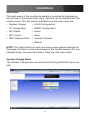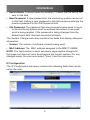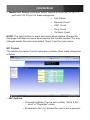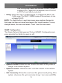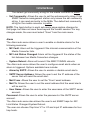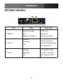
1
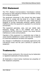
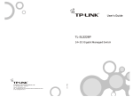
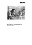
Managed 10/100 Mbps
RJ45 to Multimode
ST Fiber Media Converter
MMC110MMST
Instruction Manual
FCC Compliance Statement
This equipment has been tested and found to comply with the limits for a Class B digital
device, pursuant to part 15 of the FCC Rules. These limits are designed to provide reasonable protection against harmful interference in a residential installation. This equipment generates, uses and can radiate radio frequency energy and, if not installed and
used in accordance with the instructions, may cause harmful interference to radio communications. However, there is no guarantee that interference will not occur in a particular installation. If this equipment does cause harmful interference to radio or television
reception, which can be determined by turning the equipment off and on, the user is
encouraged to try to correct the interference by one or more of the following measures:
• Reorient or relocate the receiving antenna.
• Increase the separation between the equipment and receiver.
• Connect the equipment into an outlet on a circuit different from that to which the receiver
is connected.
• Consult the dealer or an experienced radio/TV technician for help.
Use of Trademarks, Registered Trademarks, and other Protected Names and Symbols
This manual may make reference to trademarks, registered trademarks, and other
protected names and/or symbols of third-party companies not related in any way to
StarTech.com. Where they occur these references are for illustrative purposes only and
do not represent an endorsement of a product or service by StarTech.com, or an endorsement of the product(s) to which this manual applies by the third-party company in
question. Regardless of any direct acknowledgement elsewhere in the body of this document, StarTech.com hereby acknowledges that all trademarks, registered trademarks,
service marks, and other protected names and/or symbols contained in this manual and
related documents are the property of their respective holders.
Instruction Manual
Table of Contents
Introduction ..................................................................... 1
Installation........................................................................ 2
Connecting to Power..................................................................2
Configuration and Management..................................... 3
Web Browser Configuration......................................................3
Logging Out Of The Monitoring System...................................3
System Change Menu..............................................................4
IP Configuration........................................................................5
MC Status.................................................................................6
MC Control...............................................................................7
MAC Address Filter..................................................................9
VLAN Configuration..................................................................9
SNMP Configuration.................................................................10
Telnet Management....................................................................12
Specifications................................................................... 14
LED Status Indicators...................................................... 15
Technical Support............................................................ 16
Warranty Information....................................................... 16
i
Instruction Manual
Introduction
Thank you for purchasing a StarTech.com Managed 10/100 Mbps RJ45
to Multimode ST Fiber Media Converter. A perfect solution for large, high
speed networks that require expansion of fast Ethernet networks over
long distances, the MMC110MMST acts as a standalone device allowing
for one-channel media conversion between 10/100 Base-TX and 100
Base-FX network segments.
Featuring fully integrated managed software, and support for Telnet,
SNMP v1 and v2 and Web Browser management, the MMC110MMST
ensures broad compatibility and maximum installation and configuration
convenience.
Features
• 10/100Mbps-Full/Half-duplex, Auto-Negotiation, Auto-MDI/MDIX
• 1024 MAC addresses
• 256Kbps of buffer memory
• Compact design and weight makes it portable and unobtrusive to carry
• Led Indicators that detect Power, Link, Activity, Duplex mode, and Col
lision status
• Provides MAC address filtering
• Supports Telnet, SNMP V1 & V2 and Web Browser Management
Package Contents
• 1 x Instruction Manual
• 1 x MMC110MMST
1
Instruction Manual
Installation
For optimal performance and safety, ensure that the MMC110MMS is
installed in an area that meets the following specifications:
• A temperature between 0 to 45° Celsius (32° and 113° Fahrenheit)
• Relative Humidity (RH) less than 95% (non condensing)
• Surrounding electrical devices that do not exceed the electromagnetic field (RFC) standards for IEC 801 3, Level 2 (3V/M) field strength
• Adequate ventilation, with the ventilation holes on each side of the equipment being clear of obstruction
• Power outlet within 1.8 meters (5.9’) of the product
Connecting to Power
Connect the AC to DC power adapter to the receptacle on the rear panel
of the MMC110MMS, then insert the corresponding plug into a standard
AC outlet with a voltage range from 100 to 240VAC.
PLEASE NOTE: A grounding strap should be worn while handling the
Media Converter as well as when plugging and unplugging the TX port
connector.
2
Instruction Manual
Configuration and Management
The MMC110MMST Media Converter can be configured and managed
through SNMP, Web browsers, and Telnet, as outlined in the following
sections:
Web Browser Configuration
Logging Into The Monitoring System
The MMC110MMS is accessible through a web browser such as Internet
Explorer. To access the MMC110MMS monitoring system, enter the default IP address of the MMC110MMS, 192.168.1.10, into your browser’s
address bar. By default, the username and password to access the
monitoring system are set to blank fields. The password can be changed
once the user has logged in; the username is not required to log into the
monitoring system and can be left blank.
Logging Out Of The Monitoring System
The MMC110MMS monitoring system does not include a separate log out
function. The system automatically ends a management session when the
browser software is closed. Logging off by closing the browser and then
logging in again may be required if changes made during a management
session do not seem to take effect on-screen.
3
Instruction Manual
Main Menu
The main menu of the monitoring system is persistently displayed on
the left side of the screen after log-in. Options can be selected with the
mouse cursor. The sub-menus available from the main menu are:
• System Change
• VLAN Configuration
• IP Configuration
• SNMP Configuration
• MC Status
• Alarm
• MC Control
• Save
• MAC Address Filter • Update Firmware
• Reboot
NOTE: The Apply button on each sub-menu page applies changes for
that page, but does not save them beyond the current session. For any
changes made, the user must select Save from the main menu.
System Change Menu
The System Change menu contains the following fields that users can
edit:
4
Instruction Manual
• Device Name: A device name for the MMC110MMS can be set by the
user in this field.
• New Password: A new password for the monitoring system can be set
in this field. Setting a new password in this field requires entering the
previous password in the Old Password field.
• Old Password: The password that was previously being used to log in
to the monitoring system must be entered here when a new password is being applied. If the password is being changed from the
default blank field, this field should be left blank.
The System Change menu also contains two fields that display reference
information:
• Version: The version of software currently being used.
• MAC Address: The MAC address assigned to the MMC110MMS.
NOTE: The Apply button in each sub-menu page applies changes for
that page, but does not save them beyond the current session. For any
changes made, the user must select “Save” from the main menu.
IP Configuration
The IP Configuration sub-menu contains the following fields that can be
set by the user:
5
Instruction Manual
• DHCP: Allows the user to set DHCP to “Enable” or “Disable”. If DHCP
is enabled the MMC110MMS will set its’ IP address according to
a DHCP server. This IP will replace any other IP address that the
Media Converter had been using.
• IP Address: Allows the user to set an IP address for the MMC110MMS. The default address is 192.168.1.10.
• Netmask: Allows the user to set the Netmask or subnet mask. The
default is 255.255.255.0.
• Default Gateway: Allows the user to set the gateway address of the
MMC110MMS in the network. The default is 192.168.1.254.
NOTE: The Apply button in each sub-menu page applies changes for
that page, but does not save them beyond the current session. For any
changes made, the user must select “Save” from the main menu.
MC Status
The Media Converter Status sub-menu contains the following reference
fields for a user to view:
• Operation Status: Normal, Hardware Fault or Software Fault
6
Instruction Manual
• Media Port Status: Individual status reports for both the 10/100 TX
port and 100 FX port in these categories:
• Link Status
• Receive Count
• CRC Count
• Drop Count
• Collision Count
NOTE: The Apply button in each sub-menu page applies changes for
that page, but does not save them beyond the current session. For any
changes made, the user must select “Save” from the main menu.
MC Control
The Media Converter Control sub-menu contains three main categories
of fields:
• MC Options:
• Forwarding Mode: Can be set to either “Store & Forward” or “Repeater” mode.
• Broadcast Limit (%): Allows the user to set a percent7
Instruction Manual
age limit on how much bandwidth is allocated for
broadcast traffic passing through the MMC110MMS.
If Broadcast Storm Protection is enabled on either or
both of the ports, the Broadcast Limit percentage will
be applied on the data packets using that port.
• Media Port 1: 10/100 TX
• Port Mode: Allows the user to set the port mode to
Auto, 10 Half Duplex (HD), 10 Full Duplex (FD),
100HD, or 100FD.
• Flow Control: Allows the user to enable or disable Flow
Control. If Flow Control is enabled, the input and
output rates are set in subsequent fields.
• Broadcast Storm Protection: Allows the user to enable
or disable Broadcast Storm Protection, according to
the parameters set in the Broadcast Limit (%) field.
• Output Rate: Allows the user to select the output rate
for this port from the following options: Full, 6%, 12%,
18%, 24%, 30%, 36%, 42%, 48%, 54%, 60%, 66%,
72%, 78%, 84%, or 90%.
• Input Rate: Allows the user to select the input rate for
this port from the following options: Full, 6%, 12%,
18%, 24%, 30%, 36%, 42%, 48%, 54%, 60%, 66%,
72%, 78%, 84%, or 90%.
Media Port 2: 100 FX
• Port Mode: Allows the user to set the port mode to Auto,
10HD, 10FD, 100HD, or 100FD.
• Flow Control: Allows the user to enable or disable Flow
Control. If Flow Control is enabled, the input and
output rates are set in subsequent fields.
• Broadcast Storm Protection: Allows the user to enable
or disable Broadcast Storm Protection, according to
the parameters set in the Broadcast Limit (%) field.
8
Instruction Manual
NOTE: The Apply button in each sub-menu page applies changes for
that page, but does not save them beyond the current session. For any
changes made, the user must select “Save” from the main menu.
MAC Address Filter
The MAC Address Filter sub-menu contains fields for each of the two
ports on the MMC110MMS that allows the user to enable MAC address
filtering for specific addresses. If one or more MAC addresses are enabled, the filter process is turned on and only those MAC addresses that
are enabled will be able to pass through the MMC110MMS. All packets
with MAC addresses that are not listed will be blocked.
NOTE: The Apply button in each sub-menu page applies changes for
that page, but does not save them beyond the current session. For any
changes made, the user must select “Save” from the main menu.
VLAN Configuration
The VLAN Configuration sub-menu has four main columns of fields:
• Active: Allows the user to enable VLAN configuration
• VLAN ID: Allows the user to enter a VLAN ID number.
• VLAN Member: Allows the user to configure which ports will be added 9
Instruction Manual
to a VLAN group. Users can choose TX Port, FX Port, or Mgmt Port. If Mgmt Port is selected, one of TX Port or FX Port must also be selected.
• Untag: Allows the user to enable tagged or untagged VLAN for that VLAN group. The MMC110MMS supports a maximum of one untagged VLAN.
NOTE: The Apply button in each sub-menu page applies changes for
that page, but does not save them beyond the current session. For any
changes made, the user must select “Save” from the main menu.
SNMP Configuration
The Simple Network Management Protocol (SNMP) Configuration submenu provides four fields for users to edit:
• System Contact: Allows the user to enter the name of the person in
charge of the network system.
• System Location: Allows the user to set the location of the network
system.
• Get Community: Allows the user to set the getcommunity string. If the
system only knows the get community string, it can only read MIBs.
10
Instruction Manual
The default get community string for the media converter is public.
• Set Community: Allows the user to set the setcommunity string. If the
SNMP Network management station only knows the set community
string, it can read and write to the MIBs. The default set community
string for the media converter is public.
NOTE: The Apply button in each sub-menu page applies changes for
that page, but does not save them beyond the current session. For any
changes made, the user must select “Save” from the main menu.
Alarm
The Alarm sub-menu allows a user to enable or disable alarms for the
following scenarios:
• MC Fault: Alarm will be triggered if the internal communication of the
Media Converter fails.
• MC Link Status Changed: Alarm will be triggered if the status of the
link between two Media Converters changes.
• System Reboot: Alarm will sound if the MMC110MMS reboots.
The Alarm sub-menu allows the user to configure email alerts when an
alarm is triggered. Options available here include:
• Alarm by SMTP: Allows the user to enable or disable email alerts.
• SMTP Server Address: Allows the user to set the IP address of the
server that will send the email alert.
• Mail From: Allows the user to set the “From” email address.
• Mail To: Allows the user to set the email address that the email alerts
will be sent to.
• User Name: Allows the user to enter the username of the SMTP server
account.
Password: Allows the user to enter the password of the SMTP server
account.
The Alarm sub-menu also allows the user to set SNMP traps for: MC
Link-Status Changed System Reboot.
The user can choose Trap Host V1 or V2 and input IP addresses for four
trap hosts.
11
Instruction Manual
NOTE: The Apply button in each sub-menu page applies changes for
that page, but does not save them beyond the current session. For any
changes made, the user must select “Save” from the main menu.
Save
The Save sub-menu allows the user to confirm any changes that have
been made in the monitoring system. If changes are not confirmed with
this function, they will not be stored in the MMC110MMS.
Update Firmware
The Update Firmware sub-menu allows the user to download new firmware for the MMC110MMS. There are two fields in this sub-menu:
• TFTP Server IP Address: Allows the user to enter the IP address of
the server that the new firmware will be downloaded from.
• File Name: Allows the user to enter the file name of the firmware to be
installed.
Once the information in the fields is correct, pressing the Upgrade button
begins the installation. Pressing the Reset button will clear the fields.
Reboot
The Reboot sub-menu allows the user to reboot the MMC110MMS.
Rebooting through this menu will require a new log-in to the monitoring
system after the MMC110MMS is successfully rebooted.
Telnet Management
To begin managing the MMC110MMS through Telnet, log in to the Media
Converter by entering your password; the username field is not required
by the device. The following commands are available from the Main
Screen:
• Get Command - Usage: get(g) <OPTION>
12
Instruction Manual
mc-status(ms)..........Get central MC status
mc-config(mc)..........Get central MC configuration
netconf(nc)..........Get networking configuration
sysinfo(si)..........Get system information
• Set Command - Usage: set(s) <OPTION>
mc-mode(mm)..........Set central MC operation mode
port-mode(pm)..........Set central MC port mode
port-rate(pr)..........Set central MC port rate
netconf(nc)..........Set networking configuration
sysadmin(sa)..........Set system administrator
13
Instruction Manual
Specifications
Applicable Standards
IEEE802.3 10Base-T
IEEE802.3u 100Base-TX/100Base-FX
Ports
1-port 10/100Base-TX with RJ-45 connector
1-port 100Base-FX with fiber optic connector
Speed
100Base-TX: 200Mbps full duplex
100Mbps half duplex
10Base-T: 20Mbps full duplex
10Mbps half duplex
Performance
148,810pps forwarding rate for 100Mbps
14,880pps forwarding rate for 10Mbps
Port LED
Indicators
Unit: PW/FA
TX: LK/AT, FD/CL
FX: LK/AT
Dimensions
80mm (W) x 145mm (D) x 20mm (H)
(3.15” (W) x 5.71” (D) x 0.79” (H))
Weight
150g (0.33lb.)
Power Input
0.27A @ 12VDC
Power Consumption
3.24W Max.
Operating Temperature
0 ° C ~ 45 ° C (32 ° F ~ 113 ° F)
Storage Temperature
-10 ° C ~ 70 ° C (14 ° F ~ 158 ° F)
Humidity
5 ~ 95%, non condensing
Emissions
FCC Part 15 Class A, CE Mark Class A
14
Instruction Manual
LED Status Indicators
2
3
1
LED
1. PW/FA
State
Steady (Green)
Power On
Off
Power Off
Steady (Orange)
Booting or failed
Steady
2. LK/AT
3. FD/CL
Indication
Valid connection
Flashing
Transmitting/receiving
Off
No connection
Steady
Full duplex mode
Flashing
Collision occurred
Off
Half duplex mode
15
Instruction Manual
Technical Support
StarTech.com’s lifetime technical support is an integral part of our commitment to provide industry-leading solutions. If you ever need help with your
product, visit www.startech.com/support and access our comprehensive
selection of online tools, documentation, and downloads.
Warranty Information
This product is backed by a one year warranty.
In addition, StarTech.com warrants its products against defects in materials and workmanship for the periods noted, following the initial date of
purchase. During this period, the products may be returned for repair,
or replacement with equivalent products at our discretion. The warranty
covers parts and labor costs only. StarTech.com does not warrant its
products from defects or damages arising from misuse, abuse, alteration,
or normal wear and tear.
Limitation of Liability
In no event shall the liability of StarTech.com Ltd. and StarTech.com USA
LLP (or their officers, directors, employees or agents) for any damages
(whether direct or indirect, special, punitive, incidental, consequential, or
otherwise), loss of profits, loss of business, or any pecuniary loss, arising
out of or related to the use of the product exceed the actual price paid
for the product. Some states do not allow the exclusion or limitation of
incidental or consequential damages. If such laws apply, the limitations or
exclusions contained in this statement may not apply to you.
16
StarTech.com has been making “hard-to-find easy” since 1985,
providing high quality solutions to a diverse IT and A/V customer
base that spans many channels, including government, education
and industrial facilities to name just a few. We offer an unmatched
selection of computer parts, cables, A/V products, KVM and Server Management solutions, serving a worldwide market through our
locations in the United States, Canada, the United Kingdom and
Taiwan.
Visit www.startech.com today for complete information about all
our products and to access exclusive interactive tools such as the
Cable Finder, Parts Finder and the KVM Reference Guide.