1
Keysight E3632A
DC Power Supply
Service Guide
Notices
© Keysight Technologies 1997 - 2014
Warranty
No part of this manual may be reproduced in
any form or by any means (including electronic storage and retrieval or translation
into a foreign language) without prior agreement and written consent from Keysight
Technologies as governed by United States
and international copyright laws.
The material contained in this document is
provided “as is,” and is subject to change,
without notice, in future editions. Further,
to the maximum extent permitted by the
applicable law, Keysight disclaims all
warranties, either express or implied, with
regard to this manual and any information
contained herein, including but not limited
to the implied warranties of merchantability and fitness for a particular purpose.
Keysight shall not be liable for errors or for
incidental or consequential damages in
connection with the furnishing, use, or
performance of this document or of any
information contained herein. Should Keysight and the user have a separate written
agreement with warranty terms covering
the material in this document that conflict
with these terms, the warranty terms in
the separate agreement shall control.
Manual Part Number
E3632-90010
Edition
Edition 8, November 2014
Keysight Technologies
1400 Fountaingrove Parkway
Santa Rosa, CA 95403
Technology Licenses
The hardware and or software described in
this document are furnished under a license
and may be used or copied only in accordance with the terms of such license.
Restricted Rights Legend
U.S. Government Restricted Rights. Software and technical data rights granted to
the federal government include only those
rights customarily provided to end user customers. Keysight provides this customary
commercial license in Software and technical data pursuant to FAR 12.211 (Technical
Data) and 12.212 (Computer Software) and,
for the Department of Defense, DFARS
252.227-7015 (Technical Data - Commercial
Items) and DFARS 227.7202-3 (Rights in
Commercial Computer Software or Computer Software Documentation).
II
Safety Notices
CAUTION
A CAUTION notice denotes a hazard. It calls attention to an operating procedure, practice, or the likes
of that, if not correctly performed
or adhered to, could result in damage to the product or loss of important data. Do not proceed beyond a
CAUTION notice until the indicated
conditions are fully understood and
met.
WA R N I N G
A WARNING notice denotes a
hazard. It calls attention to an
operating procedure, practice, or
the likes of that, if not correctly
performed or adhered to, could
result in personal injury or death.
Do not proceed beyond a WARNING notice until the indicated
conditions are fully understood
and met.
E3632A Service Guide
Safety Symbols
The following symbols on the instrument and in the documentation
indicate precautions which must be taken to maintain safe operation of
the instrument.
Caution, risk of danger (refer to this manual
for specific Warning or Caution information)
In position of a bi-stable push control
DC (Direct current or voltage)
Terminal is at earth potential. Used for
measurement and control circuits designed to
be operated with one terminal at earth
potential.
AC (Alternating current or voltage)
Positive binding post
Protective conductor terminal
Negative binding post
Out position of a bi-stable push control
Earth (ground) terminal
E3632A Service Guide
III
Safety Considerations
Read the information below before using this instrument.
The following general safety precautions must be observed during all
phases of operation, service, and repair of this instrument. Failure to
comply with these precautions or with specific warnings elsewhere in this
manual violates safety standards for design, manufacture, and intended
use of the instrument. Keysight Technologies assumes no liability for the
customer’s failure to comply with these requirements.
CAUTION
• Use the device with the cables provided with the shipment.
• If the device is used in a manner not specified by the manufacturer,
the device protection may be impaired.
• Always use a dry cloth to clean the device. Do not use ethyl alcohol
or any other volatile liquid to clean the device.
• Do not permit any blockage of the ventilation holes of the device.
IV
E3632A Service Guide
WA R N I N G
• Do not use MAINS supply cords by inadequately RATED cord.
Always use the MAINS supply cord provided by the manufacturer.
• Do not use the device if it appears damaged or defective. REMOVE
POWER and do not use the device until safe operation is verified
by service-trained personnel. If necessary, return the device to
Keysight for service and repair to ensure that the safety features
are maintained.
• Do not operate the device around flammable gases or fumes,
vapor, or wet environments.
• Observe all markings on the device before connecting any wiring
to the device.
• Turn off the output of the power supply before connecting to the
output terminals.
• When servicing the device, use only the specified replacement
parts.
• Do not install substitute parts or perform any unauthorized
modification to the device. Return the device to Keysight for
service and repair to ensure that the safety features are
maintained.
• Do not operate the device with the cover removed or loosened.
This power supply is a Safety Class I instrument, which means that it has a
protective earth terminal. That terminal must be connected to earth
ground through a power source with a 3-wire ground receptacle.
Before installation or operation, check the power supply and review this
manual for safety markings and instructions. Safety information for
specific procedures is located at the appropriate places in this manual.
E3632A Service Guide
V
Safety and EMC Requirements
This power supply is designed to comply with the following safety and
Electromagnetic Compatibility (EMC) requirements:
• IEC61326-1:2005/EN61326-1:2006
• Canada: ICES/NMB-001: Issue 4, June 2006
• Australia/New Zealand: AS/NZS CISPR11:2004
• IEC 61010-1:2001/EN 61010-1:2001
• Canada: CAN/CSA-C22.2 No. 61010-1-04
• USA: ANSI/UL 61010-1:2004
Environmental Conditions
This instrument is designed for indoor use and in an area with low
condensation. The table below shows the general environmental
requirements for this instrument.
VI
Environmental condition
Requirements
Temperature
Operating condition
• 0 °C to 40 °C (full rated output)
Storage condition
• –20 °C to 70 °C
Humidity
Up to 80% RH
Altitude
Up to 2000 m
Installation category
II (for indoor use)
Pollution degree
2
E3632A Service Guide
Regulatory Markings
The CE mark is a registered trademark
of the European Community. This CE
mark shows that the product complies
with all the relevant European Legal
Directives.
The C-tick mark is a registered
trademark of the Spectrum
Management Agency of Australia. This
signifies compliance with
the Australia EMC Framework
regulations under the terms of the
Radio Communication Act of 1992.
ICES/NMB-001 indicates that this ISM
device complies with the Canadian
ICES-001.
Cet appareil ISM est confomre a la
norme NMB-001 du Canada.
This instrument complies with the
WEEE Directive (2002/96/EC) marking
requirement. This affixed product label
indicates that you must not discard
this electrical or electronic product in
domestic household waste.
The CSA mark is a registered
trademark of the Canadian Standards
Association.
This symbol indicates the time period
during which no hazardous or toxic
substance elements are expected to
leak or deteriorate during normal use.
Forty years is the expected useful life
of the product.
This symbol is a South Korean Class A
EMC Declaration. This is a Class A
instrument suitable for professional
use and in electromagnetic
environment outside of the home.
E3632A Service Guide
VII
Waste Electrical and Electronic Equipment (WEEE) Directive 2002/96/EC
This instrument complies with the WEEE Directive (2002/96/EC) marking
requirement. This affixed product label indicates that you must not discard
this electrical or electronic product in domestic household waste.
Product Category:
With reference to the equipment types in the WEEE directive Annex 1, this
instrument is classified as a “Monitoring and Control Instrument” product.
The affixed product label is as shown below.
Do not dispose in domestic household waste.
To return this unwanted instrument, contact your nearest Keysight Service
Center, or visit
www.keysight.com/environment/product
for more information.
VIII
E3632A Service Guide
Declaration of Conformity (DoC)
The Declaration of Conformity (DoC) for this instrument is available on the
Keysight Web site. You can search the DoC by its product model or
description at the Web address below.
http://www.keysight.com/go/conformity
NOTE
E3632A Service Guide
If you are unable to search for the respective DoC, contact your local
Keysight representative.
IX
THIS PAGE HAS BEEN INTENTIONALLY LEFT BLANK.
X
E3632A Service Guide
Table of Contents
1
Calibration Procedures
Closed-Case Electronic Calibration
Keysight Calibration Services
Calibration Interval
2
2
2
Automating Calibration Procedures
Recommended Test Equipment
Test Considerations
3
4
5
Performance Verification Tests 6
Self-test 6
Performance verification tests 7
Measurement Techniques 8
Setup for most tests 8
Electronic load 9
Current-monitoring resistor
Programming 10
9
Constant Voltage (CV) Verifications 11
Constant voltage test setup 11
Voltage programming and readback accuracy 11
CV load regulation 12
CV line regulation 13
Normal mode voltage noise (CV ripple and noise) 14
Load transient response time 15
Constant Current (CC) Verifications 16
Constant current test setup 16
Current programming and readback accuracy
CC load regulation 17
CC line regulation 18
E3632A Service Guide
16
XI
Normal mode current noise (CC ripple and noise)
Common Mode Current Noise
19
21
Performance Test Record for E3632A
CV performance test record 22
CC performance test record 23
22
Calibration Security Code 24
To unsecure the power supply for calibration 25
To unsecure the power supply without the security code
Calibration Count
26
28
Calibration Message
28
General Calibration/Adjustment Procedure
Voltage and OVP calibration 30
Current and OCP calibration 33
Aborting a Calibration in Progress
Calibration Record for E3632A
29
36
37
Error Messages 38
System error messages 38
Self-test error messages 39
Calibration error messages 40
Calibration Program
2
41
Service
Operating Checklist
48
Types of Service Available 49
Standard repair service (worldwide)
Repacking for Shipment
50
Electrostatic Discharge (ESD) Precautions
Surface Mount Repair
XII
49
51
51
E3632A Service Guide
To Replace the Power-Line Fuse
52
To Disconnect the Output Using an External Relay 52
Installation procedure for an external relay 53
Troubleshooting Hints 54
Unit is inoperative 54
Unit reports errors 740 to 750
Unit fails self-test 55
Bias supplies problems 55
55
Self-Test Procedures 57
Power-on self-test 57
Complete self-test 57
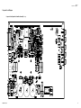
Component Locator Diagram 61
Component locator diagram for the main board assembly —
top 61
Component locator diagram for the front panel — top 62
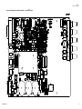
Component locator diagram for the main board assembly — top
(serial MY53xx6xxx) 63
Component locator diagram for the front panel — top (serial
MY53xx6xxx) 64
E3632A Service Guide
XIII
THIS PAGE HAS BEEN INTENTIONALLY LEFT BLANK.
XIV
E3632A Service Guide
List of Figures
Figure 1-1 Performance verification test setup 8
Figure 1-2 Transient response time 15
E3632A Service Guide
XV
THIS PAGE HAS BEEN INTENTIONALLY LEFT BLANK.
XVI
E3632A Service Guide
List of Tables
Table 1-1
Table 1-2
Table 1-3
Table 1-4
Table 1-5
Table 1-6
Table 1-7
Table 1-8
Table 2-1
Table 2-2
Table 2-3
E3632A Service Guide
Recommended test equipment 4
CV performance test record 22
CC performance test record 23
Parameters for calibration 29
Calibration record for E3632A 37
System error messages 38
Self-test error messages 39
Calibration error messages 40
Bias supplies voltages 55
Bias supplies voltages (serial MY53xx6xxx) 56
Self-test error messages 57
XVII
THIS PAGE HAS BEEN INTENTIONALLY LEFT BLANK.
XVIII
E3632A Service Guide
E3632A DC Power Supply
Service Guide
1
Calibration Procedures
Closed-Case Electronic Calibration 2
Keysight Calibration Services 2
Calibration Interval 2
Automating Calibration Procedures 3
Recommended Test Equipment 4
Test Considerations 5
Performance Verification Tests 6
Measurement Techniques 8
Constant Voltage (CV) Verifications 11
Constant Current (CC) Verifications 16
Common Mode Current Noise 21
Performance Test Record for E3632A 22
Calibration Security Code 24
Calibration Count 28
Calibration Message 28
General Calibration/Adjustment Procedure 29
Aborting a Calibration in Progress 36
Calibration Record for E3632A 37
Error Messages 38
Calibration Program 41
This chapter contains procedures to verify that the power
supply is operating normally and is within published
specifications.
1
Calibration Procedures
Closed-Case Electronic Calibration
Closed-Case Electronic Calibration
The power supply features closed- case electronic calibration
since no internal mechanical adjustments are required for
normal calibration. The power supply calculates correction
factors based upon the input reference value you enter. The
new correction factors are stored in non- volatile memory
until the next calibration adjustment is performed.
(Non- volatile memory does not change when power has been
switched off or after a remote interface reset.)
Keysight Calibration Services
When your power supply is due for calibration, contact your
local Keysight Service Center for a low- cost calibration. The
Keysight E3632A power supply is supported on calibration
processes which allow Keysight to provide this service at
competitive prices.
Calibration Interval
The power supply should be calibrated on a regular interval
determined by the accuracy requirements of your
application. A 1- year interval is adequate for most
applications. Keysight does not recommend extending
calibration intervals beyond 1 year for any application.
Keysight recommends that complete re- adjustment should
always be performed at the calibration interval. This will
increase your confidence that the Keysight E3632A will
remain within specification for the next calibration interval.
This criterion for re- adjustment provides the best long- term
stability.
2
E3632A Service Guide
Calibration Procedures
Automating Calibration Procedures
1
Automating Calibration Procedures
You can automate the complete verification procedures
outlined in this chapter if you have access to programmable
test equipment. You can program the instrument
configurations specified for each test over the remote
interface. You can then enter readback verification data into
a test program and compare the results to the appropriate
test limit values.
You can also enter calibration constants from the remote
interface. Remote operation is similar to the local
front- panel procedure. You can use a computer to perform
the adjustment by first selecting the required setup. The
calibration value is sent to the power supply and then the
calibration is initiated over the remote interface. The power
supply must be unsecured prior to initiating the calibration
procedure. A Keysight BASIC program for calibration over
the GPIB interface is listed at the end of this chapter.
For further details on programming the power supply, see
chapters 3 and 4 in the Keysight E3632A User's Guide.
E3632A Service Guide
3
1
Calibration Procedures
Recommended Test Equipment
Recommended Test Equipment
The test equipment recommended for the performance
verification and adjustment procedures is listed below. If the
exact instrument is not available, use the accuracy
requirements shown to select substitute calibration
standards.
Table 1-1 Recommended test equipment
Instrument
Requirements
Recommended model
Test function
GPIB controller
Full GPIB capabilities
Keysight 82341C Interface
card
Programming and readback
accuracy.
Oscilloscope
100 MHz with 20 MHz
bandwidth
Keysight 54602B
Display transient response
and ripple and noise
waveform.
RMS voltmeter
20 MHz
Digital voltmeter
Resolution: 0.1 mV
Measure rms ripple and
noise.
Keysight 34401A
Measure DC voltages.
Keysight 6063B
Measure load and line
regulations and transient
response time.
Accuracy: 0.01%
Electronic load
Voltage Range: 50 Vdc
Current Range: 10 Adc
Open and Short Switches
Transient On/Off
Resistive loads (RL)
2.1 Ω, 200 W
Measure ripple and noise.
7.5 Ω, 200 W
Current monitoring resistor
(shunt)
4
0.01 Ω, 0.01%
Constant current test setup.
E3632A Service Guide
Calibration Procedures
Test Considerations
1
Test Considerations
To ensure proper instrument operation, verify that you have
selected the correct power- line voltage prior to attempting
any test procedure in this chapter. Refer to the E3632A
User’s Guide for more information.
For optimum performance verification, all test procedures
should comply with the following recommendations.
• Assure that the calibration ambient temperature is stable
and between 20 °C and 30 °C.
• Assure ambient relative humidity is less than 80%.
• Allow a 1- hour warm- up period before verification or
calibration.
• Keep cables as short as possible, consistent with the
impedance requirements.
CAUTION
E3632A Service Guide
The tests should be performed by qualified personnel. During
performance verification tests, hazardous voltages may be present at
the outputs of the power supply.
5
1
Calibration Procedures
Performance Verification Tests
Performance Verification Tests
The performance verification tests use the power supply's
specifications listed in the E3632A User’s Guide.
You can perform two different levels of performance
verification tests:
• Self- test
A series of internal verification tests that provides high
confidence that the power supply is operational.
• Performance verification tests
These tests can be used to verify the power supply
specifications following repairs to specific circuits.
Self-test
A power- on self- test occurs automatically when you turn on
the power supply. This limited test assures you that the
power supply is operational.
The complete self- test is enabled by pressing the Recall
key (actually any front panel keys except the Error key)
and the power- line switch simultaneously and then
continuing to press the Recall key for 5 seconds. The
complete self- test will be finished in 2 more seconds.
You can also perform a self- test from the remote interface
(see chapter 3 in the E3632A User's Guide).
• If the self- test is successful, PASS is displayed on the
front panel.
• If the self- test fails, FAIL is displayed and the ERROR
annunciator turns on. If repair is required, see Chapter 2,
“Service” for further details.
• If self- test passes, you have a high confidence that the
power supply is operational.
6
E3632A Service Guide
Calibration Procedures
Performance Verification Tests
1
Performance verification tests
These tests can be used to verify the power supply
specifications following repairs to specific circuits. The
following sections explain all verification procedures in
detail. All of the performance test specifications are shown
in each test.
E3632A Service Guide
7
1
Calibration Procedures
Measurement Techniques
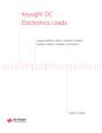
Measurement Techniques
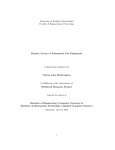
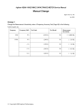
Setup for most tests
Most tests are performed at the front terminals as shown in
the following figure. Measure the DC voltage directly at the
(+) and (–) terminals on the front panel.
Figure 1-1 Performance verification test setup
8
E3632A Service Guide
Calibration Procedures
Measurement Techniques
1
Electronic load
Many of the test procedures require the use of a variable
load resistor capable of dissipating the required power.
Using a variable load resistor requires that switches be used
to connect, disconnect, and short the load resistor. An
electronic load, if available, can be used in place of a
variable load resistor and switches. The electronic load is
considerably easier to use than load resistors. It eliminates
the need for connecting resistors or rheostats in parallel to
handle power, it is much more stable than carbon- pile load,
and it makes easy work of switching between load conditions
as is required for the load regulation and load transient
response tests. Substitution of the electronic load requires
minor changes to the test procedures in this chapter.
Current-monitoring resistor
To eliminate output current measurement error caused by
the voltage drops in the leads and connections, connect the
current monitoring resistor between the (–) output terminal
and the load as a four- terminal device. Connect the
current- monitoring leads inside the load- lead connections
directly at the monitoring points on the resistor element (see
RM in Figure 1- 1).
E3632A Service Guide
9
1
Calibration Procedures
Measurement Techniques
Programming
Most performance tests can be performed only from the
front panel. However, a GPIB or RS- 232 controller is
required to perform the voltage and current programming
accuracy and readback accuracy tests.
The test procedures are written assuming that you know
how to program the power supply either from the front
panel or from a GPIB or RS- 232 controller. Complete
instructions on front panel and remote programming are
given in the E3632A User's Guide.
10
E3632A Service Guide
Calibration Procedures
Constant Voltage (CV) Verifications
1
Constant Voltage (CV) Verifications
Constant voltage test setup
If more than one meter or a meter and an oscilloscope are
used, connect each to the (+) and (–) terminals by a
separate pair of leads to avoid mutual coupling effects. Use a
coaxial cable or shielded 2- wire cable to avoid noise pick- up
on the test leads.
Voltage programming and readback accuracy
This test verifies that the voltage programming and the GPIB
or RS- 232 readback functions are within specifications. Note
that the readback values over the remote interface should be
identical to those displayed on the front panel.
NOTE
You should program the power supply over the remote interface for this
test to avoid round-off errors.
1 Turn off the power supply and connect a digital voltmeter
between the (+) and (–) terminals of the output to be
tested as shown in Figure 1- 1.
2 Turn on the power supply. Select the 30 V/4 A range and
enable the outputs by sending the commands:
VOLT:RANG P30V
OUTP ON
3 Program the output voltage to zero volt and current to
full rated value (4.0 A) by sending the commands:
VOLT 0
CURR 4
E3632A Service Guide
11
1
Calibration Procedures
Constant Voltage (CV) Verifications
4 Record the output voltage reading on the digital voltmeter
(DVM). The reading should be within the limits of
0 V ±10 mV. Note that the CV, Adrs, Limit, and Rmt
annunciators are on.
5 Readback the output voltage over the remote interface by
sending the command:
MEAS:VOLT?
6 Record the value displayed on the controller. This value
should be within the limits of DVM ±5 mV.
7 Program the output voltage to full rated value (30.0 V) by
sending the command.
VOLT 30.0
8 Record the output voltage reading on the digital voltmeter
(DVM). The readings should be within the limits of
30 V ±25 mV.
9 Readback the output voltage over the remote interface by
sending the command:
MEAS:VOLT?
10 Record the value displayed on the controller. This value
should be within the limits of DVM ±20 mV.
CV load regulation
This test measures the immediate change in the output
voltage resulting from a change in the output current from
full to no load.
1 Turn off the power supply and connect a digital
voltmeter between the (+) and (–) terminals of the output
to be tested as shown in Figure 1- 1.
2 Turn on the power supply. Select the 30 V/4 A range,
enable the output, and set the display to the limit mode.
When the display is in the limit mode, program the
output current to the maximum programmable value and
the voltage to the full rated value (30.0 V).
12
E3632A Service Guide
Calibration Procedures
Constant Voltage (CV) Verifications
1
3 Operate the electronic load in constant current mode and
set its current to 4.0 A. Check that the front panel CV
annunciator remains lit. If not lit, adjust the load so that
the output current drops slightly until the CV annunciator
lights. Record the output voltage reading on the digital
voltmeter.
4 Operate the electronic load in open mode (input off).
Record the output voltage reading on the digital voltmeter
immediately. The difference between the digital voltmeter
readings in steps 3 and 4 is the CV load regulation. The
difference of the readings during the immediate change
should be within the limit of 5 mV.
CV line regulation
This test measures the immediate change in output voltage
that results from a change in AC line voltage from the
minimum value (10% below the nominal input voltage) to
maximum value (10% above the nominal input voltage).
1 Turn off the power supply and connect a digital voltmeter
between the (+) and (–) terminals of the output to be
tested as shown in Figure 1- 1.
2 Connect the AC power line through a variable voltage
transformer.
3 Turn on the power supply. Select the 30 V/4 A range,
enable the output, and set the display to the limit mode.
When the display is in the limit mode, program the
current to the maximum programmable value and the
voltage to full rated value (30.0 V).
4 Operate the electronic load in constant current mode and
set its current to 4.0 A. Check that the CV annunciator
remains lit. If not lit, adjust the load so that the output
current drops slightly until the CV annunciator lights.
5 Adjust the transformer to low line voltage limit (104 Vac
for nominal 115 Vac, 90 Vac for nominal 100 Vac, or
207 Vac for nominal 230 Vac). Record the output reading
on the digital voltmeter.
E3632A Service Guide
13
1
Calibration Procedures
Constant Voltage (CV) Verifications
6 Adjust the autotransformer to high line voltage (127 Vac
for nominal 115 Vac, 110 Vac for nominal 100 Vac, or
253 Vac for nominal 230 Vac). Record the voltage reading
on the digital voltmeter immediately. The difference
between the digital voltmeter readings in steps 5 and 6 is
the CV line regulation. The difference of the readings
during the immediate change should be within the limit of
5 mV.
Normal mode voltage noise (CV ripple and noise)
The normal mode voltage noise is in the form of ripple
related to the line frequency plus some random noise. The
normal mode voltage noise is specified as the rms or
peak- to- peak output voltage in a frequency range from
20 Hz to 20 MHz.
1 Turn off the power supply and connect the output to be
tested as shown in Figure 1- 1 to an oscilloscope
(AC coupled) between (+) and (–) terminals. Set the
oscilloscope to AC mode and bandwidth limit to 20 MHz.
Connect a resistive load (7.5 Ω) as shown in Figure 1- 1.
2 Turn on the power supply. Select the 30 V/4 A range,
enable the output, and set the display to the limit mode.
When the display is in the limit mode, program the
current to the full rated value (4.0 A) and the voltage to
the full rated value (30.0 V).
3 Check that the front panel CV annunciator remains lit. If
not lit, adjust the load down slightly.
4 Note that the waveform on the oscilloscope does not
exceed the peak- to- peak limit of 2 mV.
5 Disconnect the oscilloscope and connect an AC RMS
voltmeter in its place. The rms voltage reading does not
exceed the rms limit of 0.35 mV.
14
E3632A Service Guide
Calibration Procedures
Constant Voltage (CV) Verifications
1
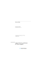
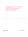
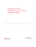
Load transient response time
This test measures the time for the output voltage to recover
to within 15 mV of nominal output voltage following a load
change from full load to half load, or half load to full load.
1 Turn off the power supply and connect the output to be
tested as shown in Figure 1- 1 with an oscilloscope.
Operate the electronic load in constant current mode.
2 Turn on the power supply. Select the 30 V/4 A range,
enable the outputs, and set the display to the limit mode.
When the display is in the limit mode, program the
current to the full rated value 4.0 A and the voltage to
the full rated value (30.0 V).
3 Set the electronic load to transient operation mode
between one half of the output's full scale value and the
output's full rated value at a 1 kHz rate with 50% duty
cycle.
4 Set the the oscilloscope for AC coupling, internal sync,
and lock on either the positive or negative load transient.
5 Adjust the the oscilloscope to display transients as shown
in Figure 1- 2. Note that the pulse width (t2–t1) of the
transients at 15 mV from the base line is no more than
50 msec for the output.
Figure 1-2 Transient response time
E3632A Service Guide
15
1
Calibration Procedures
Constant Current (CC) Verifications
Constant Current (CC) Verifications
Constant current test setup
Follow the general setup instructions in the “Measurement
Techniques” on page 8 and the specific instructions given in
the following paragraphs.
Current programming and readback accuracy
This test verifies that the current programming and the
GPIB or RS- 232 readback functions are within specifications.
Note that the readback values over the remote interface
should be identical to those displayed on the front panel.
The accuracy of the current monitoring resistor must be
0.01% or better.
NOTE
You should program the power supply over the remote interface for this
test to avoid round-off errors.
1 Turn off the power supply and connect a 0.01 Ω current
monitoring resistor (RM) across the output to be tested
and a digital voltmeter (DVM) across the current
monitoring resistor (RM).
2 Turn on the power supply. Select the 15 V/7 A range and
enable the output by sending the commands:
VOLT:RANG P15V
OUTP ON
3 Program the output voltage to full rated voltage (15.0 V)
and output current to zero amp by sending the
commands:
VOLT 15
16
E3632A Service Guide
Calibration Procedures
Constant Current (CC) Verifications
1
CURR 0
4 Divide the voltage drop (DVM reading) across the current
monitoring resistor (RM) by its resistance to convert to
amps and record this value (IO). This value should be
within the limits of 0 A ±10 mA. Also, note that the CC,
Adrs, Limit, and Rmt annunciators are on.
5 Readback the output current over the remote interface by
sending the command:
MEAS:CURR?
6 Record the value displayed on the controller. This value
should be within the limit of IO ±5 mA.
7 Program the output current to the full rated value (7.0 A)
by sending the commands:
CURR 7.0
8 Divide the voltage drop (DVM reading) across the current
monitoring resistor (RM) by its resistance to convert to
amps and record this value (IO). This value should be
within the limit of 7 A ±24 mA.
9 Readback the output current over the remote interface by
sending the command:
MEAS:CURR?
10 Record the value displayed on the controller. This value
should be within the limit IO ±15.5 mA.
CC load regulation
This test measures the immediate change in output current
resulting from a change in the load from full- rated output
voltage to short circuit.
1 Turn off the power supply and connect the output to be
tested as shown in Figure 1- 1 with the digital voltmeter
connected across the 0.01Ω current monitoring resistor
(RM).
E3632A Service Guide
17
1
Calibration Procedures
Constant Current (CC) Verifications
2 Turn on the power supply. Select the 15 V/7 A range,
enable the output, and set the display to the limit mode.
When the display is in the limit mode, program the
output voltage to the maximum programmable value and
the output current to the full rated value (7.0 A).
3 Operate the electronic load in constant voltage mode and
set its voltage to 15.0 V. Check that the CC annunciator is
on. If it is not, adjust the load so that the output voltage
drops slightly. Record the current reading by dividing the
voltage reading on the digital voltmeter by the resistance
of the current monitoring resistor.
4 Operate the electronic load in short (input short) mode.
Record the current reading immediately by dividing the
voltage reading on the digital voltmeter by the resistance
of the current monitoring resistor. The difference between
the current readings in step 3 and 4 is the load regulation
current. The difference of the readings during the
immediate change should be within the limit of 0.95 mA.
CC line regulation
This test measures the immediate change in output current
that results from a change in AC line voltage from the
minimum value (10% below the nominal input voltage) to the
maximum value (10% above nominal voltage).
1 Turn off the power supply and connect the output to be
tested as shown in Figure 1- 1 with the digital voltmeter
connected across the current monitoring resistor (RM).
2 Connect the AC power line through a variable voltage
transformer.
3 Turn on the power supply. Select the 15 V/7 A range,
enable the output, and set the display to the limit mode.
When the display is in the limit mode, program the ouput
voltage to the maximum programmable value and the
output current to the full rated value (7.0 A).
18
E3632A Service Guide
Calibration Procedures
Constant Current (CC) Verifications
1
4 Operate the electronic load in constant voltage mode and
set its voltage to 15.0 V. Check that the CC annunciator
remains lit. If not lit, adjust the load so that the output
voltage drops slightly until the CC annunciator lights.
5 Adjust the transformer to low line voltage limit (104 Vac
for nominal 115 Vac, 90 Vac for nominal 100 Vac, or
207 Vac for nominal 230 Vac). Record the output current
reading by dividing the voltage reading on the digital
voltmeter by the resistance of the current monitoring
resistor.
6 Adjust the transformer to 10% above the nominal line
voltage (127 Vac for a 115 Vac nominal input, 110 Vac for
a 100 Vac nominal input or 253 Vac for a 230 Vac nominal
input). Record the current reading again immediately by
dividing the voltage reading on the digital voltmeter by
the resistance of the current monitoring resistor. The
difference between the current readings in step 5 and 6 is
the load regulation current. The difference of the readings
during the immediate change should be within the limit of
0.95 mA.
Normal mode current noise (CC ripple and noise)
The normal mode current noise is specified as the rms
output current in a frequency range 20 Hz to 20 MHz with
the power supply in constant current operation.
1 Turn off the power supply and connect the output to be
tested as shown in Figure 1- 1 with a load resistor (2.1 Ω)
across output terminals to be tested. Connect a RMS
voltmeter across the load resistor. Use only a resistive
load for this test.
2 Turn on the power supply. Select the 15 V/7 A range,
enable the output, and set the display to the limit mode.
When the display is in the limit mode, program the
current to full rated value (7.0 A) and the voltage to the
full rated value (15.0 V).
E3632A Service Guide
19
1
Calibration Procedures
Constant Current (CC) Verifications
3 The output current should be at the full- rated rating with
the CC annunciator on. If not lit, adjust the load so that
the output voltage drops slightly until the CC annunciator
lights.
4 Divide the reading on the RMS voltmeter by the load
resistance to obtain rms current. The readings should be
within the limit of 2 mA.
20
E3632A Service Guide
Calibration Procedures
Common Mode Current Noise
1
Common Mode Current Noise
The common mode current is that AC current component
which exists between the output or output lines and chassis
ground. Common mode noise can be a problem for very
sensitive circuitry that is referenced to earth ground. When
a circuit is referenced to earth ground, a low level
line- related AC current will flow from the output terminals
to earth ground. Any impendance to earth ground will create
a voltage drop equal to the output current flow multiplied
by the impendance.
1 Turn off the power supply and connect a 100 KΩ resistor
(RS) and a 2200 pF capacitor in parallel between the (–)
terminal and chassis ground.
2 Connect a digital voltmeter (DVM) across RS.
3 Turn on the power supply. Select the 15 V/7 A range,
enable the output, and set the display to the limit mode.
When the display is in the limit mode, program the
output to the full rated value (15.0 V and 7.0 A).
4 Record the voltage across RS and convert it to current by
dividing by the resistance (DVM reading/100 KΩ). Note
that the current is less than 1.5 μA.
E3632A Service Guide
21
1
Calibration Procedures
Performance Test Record for E3632A
Performance Test Record for E3632A
CV performance test record
Table 1-2 CV performance test record
Test description
Actual result
Specifications
Upper limit
Lower limit
CV programming accuracy @ 0 volts
(DVM reading)
+0.0100 V
–0.0100 V
CV readback accuracy @ 0 volts
DVM + 0.0050 V
DVM – 0.0050 V
CV programming accuracy @ full scale
(DVM reading)
+30.025 V
29.9750 V
CV readback accuracy @ full scale
DVM + 0.0200 V
DVM – 0.0200 V
CV load regulation
Maximum change: <5 mV
CV line regulation
Maximum change: <5 mV
CV ripple/noise
<2 mVp-p, 0.35 mVrms
Load transient response time
<50 μsec
22
E3632A Service Guide
Calibration Procedures
Performance Test Record for E3632A
1
CC performance test record
Table 1-3 CC performance test record
Test Description
Actual Result
Specifications
Upper Limit
Lower Limit
CC programming accuracy @ 0 A (IO)
+0.0100 A
–0.0100 A
CC readback accuracy @ 0 A
IO + 0.0050 A
IO – 0.0050 A
CC programming accuracy @ full scale (IO)
7.0240 A
6.9760 A
CC readback accuracy @ full scale
IO + 0.0155 A
IO – 0.0155 A
CC load regulation
Maximum change: <0.95 mA
CC line regulation
Maximum change: <0.95 mA
CC ripple/noise
<2 mA
Common mode current noise
<1.5 μArms
E3632A Service Guide
23
1
Calibration Procedures
Calibration Security Code
Calibration Security Code
This feature allows you to enter a security code (electronic
key) to prevent accidental or unauthorized calibrations of
the power supply. When you first receive your power supply,
it is secured. Before you can calibrate the power supply, you
must unsecure it by entering the correct security code. A
procedure to unsecure the power supply is given on the
following page.
• The security code is set to HP003632 when the power
supply is shipped from the factory. The security code is
stored in non- volatile memory, and it does not change
when power has been off or after a remote interface
reset.
• To secure the power supply from the remote interface, the
security code may contain up to 12 alphanumeric
characters as shown below. The first character must be a
letter, but the remaining characters can be letters or
numbers. You do not have to use all 12 characters but the
first character must always be a letter.
A _ _ _ _ _ _ _ _ _ _ _
(12 characters)
• To secure the power supply from the remote interface so
that it can be unsecured from the front panel, use the
eight- character format shown below. The first two
characters must be “H P” and the remaining characters
must be numbers. Only the last six characters are
recognized from the front panel, but all eight characters
are required. To unsecure the power supply from the front
panel, omit the “H P” and enter the remaining numbers as
shown on the following pages.
H P
_ _ _ _ _ _
(8 characters)
• If you forget your security code, you can disable the
security feature by adding a jumper inside the power
supply, and then entering a new code. Refer to “To
unsecure the power supply without the security code” on
page 26.
24
E3632A Service Guide
Calibration Procedures
Calibration Security Code
1
To unsecure the power supply for calibration
The power supply can use a calibration security code to
prevent unauthorized or accidental calibration. This
procedure shows you how to unsecure the power supply for
calibration from the front panel.
Calibrate
Power
1 Turn on the front- panel calibration mode.
SECURED
Turn on the calibration mode by pressing the Calibrate key
while simultaneously turning on the power supply then
continue to hold the Calibrate key for about 5 seconds
until a beep is heard.
If the power supply is secured, you will see the above
message from the front panel for approximately one
second. The CAL MODE message is then displayed on the
front panel.
Secure
2 Move to the security code by pressing the Secure key.
000000 CODE
3 Enter the security code using the knob and resolution
selection keys.
003632 CODE
The security code is set to “HP003632” when the power
supply is shipped from the factory. The security code is
stored in non- volatile memory and does not change when
the power has been off or after a remote interface reset.
To enter the security code from the front panel, enter
only the last six digits. To enter the security code from
the remote interface, you may enter up to 12 characters.
Use the resolution selection keys to move left or right
between digits. Use the knob to change the digits. Notice
that the security code may be different if the security
code has been changed from the default setting.
E3632A Service Guide
25
1
Calibration Procedures
Calibration Security Code
Secure
4 Unsecure the power supply.
UNSECURED
The power supply is unsecured when you press the
Secure key. You will see the above message from the
front panel for one second. The CAL MODE message is
displayed on the front panel after above message.
Power
5 Turn off the calibration mode.
Turn off the power supply to exit the calibration mode.
NOTE
To re-secure the power supply (following calibration), perform this
procedure again.
To unsecure the power supply without the security code
To unsecure the power supply without the correct security
code (when you forget the security code), follow the steps
below. Refer to “Electrostatic Discharge (ESD)
Precautions” on page 51 before beginning this procedure.
1 Disconnect the power cord and all load connections from
front terminals.
2 Remove the instrument cover.
3 Connect the power cord and turn on the calibration mode
by pressing the Calibrate key while simultaneously turning
on the power supply, and then continue to hold the
Calibrate key for about 5 seconds until a beep is heard. Be
careful not to touch the power line connections.
4 Apply a short between the two exposed metal pads on
JP5[1] (located near U13). Refer to “Component locator
diagram for the main board assembly — top” on page 61.
5 While maintaining the short, press Secure to move to the
security code and enter any unsecure code in the
calibration mode. The power supply is now unsecured.
[1] For serial MY53xx6xxx, apply the short at JP12 (located near U36). Refer to
“Component locator diagram for the main board assembly — top (serial
MY53xx6xxx)” on page 63.
26
E3632A Service Guide
Calibration Procedures
Calibration Security Code
1
6 Remove the short at JP5[1]. (An error occurs if not
removed.)
7 Turn off and reassemble the power supply. Now you can
enter a new security code. Be sure you take note of the
new security code.
[1] For serial MY53xx6xxx, remove the short at JP12.
E3632A Service Guide
27
1
Calibration Procedures
Calibration Count
Calibration Count
The calibration count feature provides an independent
“serialization” of your calibrations. You can determine the
number of times that your power supply has been calibrated.
By monitoring the calibration count, you can determine
whether an unauthorized calibration has been performed.
Since the value increments by one for each calibration
parameter (see Table 1- 4 on the next page), a complete
calibration increases the value by 5 counts.
The calibration count is stored in non- volatile memory and
does not change when power has been off or after a remote
interface reset. Your power supply was calibrated before it
left the factory. When you receive the power supply, read
the calibration count to determine its value.
The calibration count increments up to a maximum of 32,767
after which it wraps around to 0. No way is provided to
program or reset the calibration count.
Calibration Message
You can use the calibration message feature to record
calibration information about your power supply. For
example, you can store such information as the last
calibration date, the next calibration due date, the power
supply’s serial number, or even the name and phone number
of the person to contact for a new calibration.
You can record and read information in the calibration
message from the remote interface only.
The calibration message may contain up to 40 characters.
The calibration message is stored in non- volatile memory
and does not change when power has been off or after a
remote interface reset.
28
E3632A Service Guide
Calibration Procedures
General Calibration/Adjustment Procedure
1
General Calibration/Adjustment Procedure
The calibration procedures from the front panel are
described in this section. For voltage calibration, disconnect
all loads from the power supply and connect a DVM across
the output terminals. For current calibration, disconnect all
loads from the power supply, connect an appropriate current
monitoring resistor (0.01 Ω) across the output terminals, and
connect a DVM across the terminals of the monitoring
resistor.
NOTE
The power supply should be calibrated after 1-hour warm-up with no load
connected.
The following table shows calibration parameters and points
which should be used to calibrate the output voltage and
current.
Table 1-4 Parameters for calibration
Calibration parameter
Voltage/current
Calibration point mnemonic
CAL SETUP 1
Voltage
V LO
V MI
V HI
CAL SETUP 2
OVP
None
CAL SETUP 3
Current
I LO
I MI
I HI
CAL SETUP 4
E3632A Service Guide
OCP
None
29
1
Calibration Procedures
General Calibration/Adjustment Procedure
NOTE
• You can terminate any CAL SETUP without changing its calibration
constants by turning off power.
• Perform the voltage calibration prior to the OVP calibration and the
current calibration prior to the OCP calibration.
To calibrate the output voltages and currents of the power
supply from the front panel, proceed as follows:
1 Unsecure the power supply.
To calibrate the voltage and current, you must unsecure
the power supply according to the procedure given on
page 59.
2 Disconnect all loads from the power supply and connect a
DVM across output terminals.
Calibrate
Power
3 Turn on the calibration mode.
CAL MODE
Turn on the calibration mode by pressing the Calibrate key
while simultaneously turning on the power supply, and
then continue to hold the Calibrate key for about 5
seconds until a beep is heard. Make sure that the power
supply is in CV mode. If the power supply is not in CV
mode, an error occurs.
Voltage and OVP calibration
Calibrate
4 Move down a level to the voltage calibration mode.
CAL SETUP 1
The display shows the above message to indicate that the
power supply is ready for the voltage calibration.
30
E3632A Service Guide
Calibration Procedures
General Calibration/Adjustment Procedure
Calibrate
1
5 Calibrate DAC and select the low voltage calibration point.
30 LEFT
The START BITCAL message is displayed for about
3 seconds to indicate that the power supply is ready for
DAC calibration. Then it counts down numbers from
30 to 0.
V LO 0.5000 V
Then, the display shows the low voltage calibration point.
6 Read the DVM and change the low voltage value on the
display to match the measured voltage.
For example, if the DVM reading is 0.4500 V, adjust the
voltage to 0.4500 V using the knob and resolution
selection keys.
V LO 0.4500 V
Calibrate
7 Pressing the Calibrate key saves the change and selects the
middle voltage calibration point.
V MI 15.000 V
If the entered number is within an acceptable range, an
ENTERED message appears for one second. If the entered
number is not correct, a MIN VALUE or MAX VALUE message
appears for one second and the display shows the low
voltage calibration point again. The display now shows the
middle voltage calibration point.
8 Read the DVM and change the middle voltage value on the
display to match the measured voltage.
For example, if the DVM reads 14.995 V, adjust the voltage
to 14.995 V using the knob and arrow keys.
V MI 14.995 V
E3632A Service Guide
31
1
Calibration Procedures
General Calibration/Adjustment Procedure
Calibrate
9 Pressing the Calibrate key saves the change and selects the
high voltage calibration point.
V HI 29.500 V
If the entered number is within an acceptable range, a
ENTERED message appears for one second. If the entered
number is not correct, a MIN VALUE or MAX VALUE message
appears for one second and the display shows the middle
voltage calibration point again. The display now shows the
high voltage calibration point.
10 Read the DVM and change the high voltage value on the
display to match the measured voltage.
For example, if the DVM reads 28.995 V, adjust the voltage
to 28.995 V using the knob and arrow keys.
V HI 28.995 V
Calibrate
11 Pressing the Calibrate key saves the new voltage calibration
constants, and goes to the OVP calibration mode.
CAL SETUP 2
A CALIBRATING message appears for one second to
indicate that the voltage calibration is progressing and
new voltage calibration constants of “SETUP 1” are stored.
Then, the display shows above message to indicate that
the power supply is ready for the OVP calibration.
If the calibration fails, a DAC CAL FAIL or ADC CAL FAIL
message appears for one second and the display shows
the CAL SETUP 1 for voltage calibration again.
32
E3632A Service Guide
Calibration Procedures
General Calibration/Adjustment Procedure
1
Current and OCP calibration
NOTE
Connect an appropriate shunt (0.01 Ω) across the output terminals, and
connect a digital voltmeter across the shunt resistor for the current
calibration.
12 Pressing the Calibrate key saves the new calibration
constants for OVP circuit and goes to the current
calibration mode.
CAL SETUP 3
A CALIBRATING message appears for about several seconds
to indicate that the OVP calibration is progressing and
new calibration constants of “SETUP 2” are stored. Then,
the display shows the above message to indicate that the
power supply is ready for the current calibration.
If the calibration fails, a OVP CAL FAIL message appears for
one second and the display shows the CAL SETUP 2 for OVP
calibration again.
Calibrate
13 Select the low current calibration point.
I LO 0.2000 A
The display shows the low current calibration point.
14 Read the DVM and change the low current value on the
display to match the computed current (DVM reading
divided by shunt resistance).
For example, if the computed value is 0.199 A, adjust the
current to 0.199 A using the knob and arrow keys.
I LO +0.1990 A
NOTE
E3632A Service Guide
Notice that you should wait for the DVM reading to stabilize for accurate
calibration.
33
1
Calibration Procedures
General Calibration/Adjustment Procedure
Calibrate
15 Pressing the Calibrate key saves the change and selects the
middle current calibration point.
I MI 3.5000 A
If the entered number is within an acceptable range, an
ENTERED message appears for one second. If the entered
number is not correct, a MIN VALUE or MAX VALUE message
appears for one second and the display shows the low
current calibration point again. The display now shows
the middle current calibration point.
16 Read the DVM and change the middle current value on the
display to match the computed current (DVM reading
divided by shunt resistance).
For example, if the computed value is 3.499 A, adjust the
current to 3.499 A using the knob and arrow keys.
I MI 3.4990 A
NOTE
Calibrate
Notice that you should wait for the DVM reading to stabilize for accurate
calibration.
17 Pressing the Calibrate key saves the change and selects the
high current calibration point.
I HI 6.9000 A
If the entered number is within an acceptable range, an
ENTERED message appears for one second. If the entered
number is not correct, a MIN VALUE or MAX VALUE message
appears for one second and the display shows the middle
current calibration point again. The display now shows
the high current calibration point.
18 Read the DVM and change the high current value on the
display to match the computed current (DVM reading
divided by shunt resistance).
For example, if the computed value is 6.899 A, adjust the
current to 6.899 A using the knob and arrow keys.
I HI 6.8990 A
34
E3632A Service Guide
Calibration Procedures
General Calibration/Adjustment Procedure
NOTE
Calibrate
1
Notice that you should wait for the DVM reading to stabilize for accurate
calibration.
19 Pressing the Calibrate key saves the new calibration
constants for the output current and goes to the OCP
calibration mode.
CAL SETUP 4
A CALIBRATING message appears for one second to
indicate that the current calibration is progressing and
new calibration constants of “SETUP 3” are stored. Then,
the display shows the above message to indicate that the
power supply is ready for the OCP calibration.
If the calibration fails, a DAC CAL FAIL or ADC CAL FAIL
message appears for one second and the display shows
the CAL SETUP 3 for current calibration again.
Calibrate
20 Pressing the Calibrate key saves the new OCP calibration
constants and return to the calibration mode.
CAL MODE
A CALIBRATING message appears for several seconds to
indicate that the OCP calibration is progressing and new
OCP calibration constants of “SETUP 4” are stored. Then
the display will return to the calibration mode.
Power
E3632A Service Guide
21 Turn off the power supply to exit the calibration mode.
35
1
Calibration Procedures
Aborting a Calibration in Progress
Aborting a Calibration in Progress
Sometimes it may be necessary to abort a calibration after
the procedure has already been initiated. You can abort a
calibration at any time by turning the power supply off from
the front panel. When performing a calibration from the
remote interface, you can abort a calibration by issuing a
remote interface device clear message or by pressing the
front- panel Local key.
36
E3632A Service Guide
Calibration Procedures
Calibration Record for E3632A
1
Calibration Record for E3632A
Table 1-5 Calibration record for E3632A
Step
Calibration Description
1
Unsecure the power supply (see “To unsecure the power supply for
calibration” on page 25).
2
Turn on CAL MODE (simultaneously press the Calibrate and Power keys)
until it beeps.
3
Move down menu to CAL SETUP 1 (press the Calibrate key).
4
Calibrate the DAC and select the low point for voltage calibration; “START
BITCAL appears for 3 seconds and the display counts down numbers from
30 to 0. Then, “V LO 0.5000 V” appears on the display (press the Calibrate
key and wait about 30 seconds, and change the display to match the DVM
reading).
5
“V MI 15.000 V” appears on the display (press the Calibrate key and change V
the display to match the DVM reading).
Middle voltage
point calibration
6
“V HI 29.500 V” appears on the display (press the Calibrate key and change
the display to match the DVM reading).
V
High voltage point
calibration
7
“CAL SETUP“ now appears on the display (press the Calibrate key).
V
OVP calibration
8
“CAL SETUP 3” now appears on the display (press the Calibrate key and
connect 0.01 Ω resistor across the output terminals).
Current
calibration
9
“I LO 0.2000 A” appears on the display (press the Calibrate key; then change A
the display to match the computed current through 0.01 Ω resistor).
Low current point
calibration
10
“I MI 3.5000 A” appears on the display (press the Calibrate key; then change A
the display to match the computed current through 0.01 Ω resistor).
Middle current
point calibration
11
“I HI 6.9000 A” appears on the display (press the Calibrate key and change
the display to match the computed current through 0.01 Ω resistor).
A
High current point
calibration
12
“CAL SETUP 4” now appears on the display (press the Calibrate key).
A
OCP calibration
13
Press the Calibrate key, and then press the Power switch.
E3632A Service Guide
Measurement
Mode (DVM)
Supply Being
Adjusted
Voltage
Calibration
V
DAC and low
voltage point
calibration
Exit CAL MODE
37
1
Calibration Procedures
Error Messages
Error Messages
The following tables are abbreviated lists of error messages
for the E3632A. The errors listed are the most likely errors
to be encountered during calibration and adjustment. A
more complete list of error messages and descriptions is
contained in “Chapter 4” of the E3632A User's Guide.
System error messages
Table 1-6 System error messages
Error
Error Message
-330
Self-test failed
-350
Queue overflow
501
Isolator UART framing error
502
Isolator UART overrun error
503[1]
SPI data error
511
RS-232 framing error
512
RS-232 overrun error
513
RS-232 parity error
514
Command allowed only with RS-232
521
Input buffer overflow
522
Output buffer overflow
550
Command not allowed in local
[1] This error message is only applicable for serial MY53xx6xxx.
38
E3632A Service Guide
Calibration Procedures
Error Messages
1
Self-test error messages
Table 1-7 Self-test error messages
601
Front panel does not respond
602
RAM read/write failed
603
A/D sync stuck
604
A/D slope convergence failed
605
Cannot calibrate rundown gain
606
Rundown gain out of range
607
Rundown too noisy
608
Serial configuration readback failed
609[1]
System ADC test failed
624
Unable to sense line frequency
625
I/O processor does not respond
626
I/O processor failed self-test
630
Fan test failed
631
System DAC test failed
632
Hardware test failed
[1] This error message is only applicable for serial MY53xx6xxx.
E3632A Service Guide
39
1
Calibration Procedures
Error Messages
Calibration error messages
Table 1-8 Calibration error messages
40
Error
Error message
701
Cal security disabled by jumper
702
Cal secured
703
Invalid secure code
704
Secure code too long
705
Cal aborted
708
Cal output disabled
712
Bad DAC cal data
713
Bad readback cal data
714
Bad OVP cal data
715
Bad OCP cal data
716
Bad OVP DNL error correction data
717
Cal OVP or OCP status enabled
740
Cal checksum failed, secure state
741
Cal checksum failed, string data
742
Cal checksum failed, store/recall data in location 0
743
Cal checksum failed, store/recall data in location 1
744
Cal checksum failed, store/recall data in location 2
745
Cal checksum failed, store/recall data in location 3
746
Cal checksum failed, DAC cal constants
747
Cal checksum failed, readback cal constants
748
Cal checksum failed, GPIB address
749
Cal checksum failed, internal data
750
Cal checksum failed, DAC DNL error correction data
E3632A Service Guide
Calibration Procedures
Calibration Program
1
Calibration Program
This section contains a Keysight BASIC program for
calibration over the GPIB interface. This program makes
software adjustments to the E3632A power supply using a
current shunt and a digital mutimeter which is connected to
the controller. In this program a 0.01 ohm current shunt is
used. Be sure to change the value of the variable
“Current_shunt” to the value of the current shunt used and
the GPIB address for the power supply and the digital
voltmeter.
10
20
30
40
50
60
70
80
90
100
110
120
130
140
150
160
170
180
190
200
210
220
230
240
250
260
270
280
290
300
310
320
!
! This program was written on a PC with Keysight Basic for Windows.
! It will make software adjustments to the E3632A Power Supply
! on the GPIB bus using a Keysight 34401A Digital Multimeter and a
! current shunt. In the program a 0.01 ohm current shunt is
! used to measure current. Be sure to change the value of
! the variable 'Current_shunt' to the value of the current
! shunt used.
!
CLEAR SCREEN
DIM Cal_msg$[40],Error$[40],Sec_code$[10]
REAL Dmm_rdg,Current_shunt
Current_shunt=.01
! Current Shunt value in Ohms
Sec_code$="HP003632"
! Assign the security code
ASSIGN @Dmm TO 722
! Assign address 22 to the Dmm
ASSIGN @Pwrsupply TO 705
! Assign address 5 to the Power Supply
CLEAR 7
! Clear GPIB, Dmm and Power Supply
OUTPUT @Pwrsupply;"*CLS"
! Clear Power Supply errors
OUTPUT @Dmm;"*RST"
! Reset Dmm
OUTPUT @Pwrsupply;"*RST"
! Reset Power Supply
OUTPUT @Pwrsupply;"CAL:STR?"
! Read the calibration message
ENTER @Pwrsupply;Cal_msg$
PRINT TABXY(5,2),"Calibration message of Power Supply is: ";Cal_msg$
!
! Set the Calibration security to off, and check to be sure
! it is off. If not successful, print message to screen and end.
!
OUTPUT @Pwrsupply;"VOLT:PROT:STAT OFF"
OUTPUT @Pwrsupply;"CURR:PROT:STAT OFF"
OUTPUT @Pwrsupply;"CAL:SEC:STAT OFF, ";Sec_code$
OUTPUT @Pwrsupply;"CAL:SEC:STAT?"
ENTER @Pwrsupply;A
E3632A Service Guide
41
1
42
Calibration Procedures
Calibration Program
330
340
350
360
IF A=1 THEN
PRINT TABXY(5,5),"****** Unable to Unsecure the Power supply ******"
GOTO 2290
END IF
370
380
390
400
410
420
430
440
450
460
470
480
490
500
510
520
530
540
550
560
570
580
590
600
610
620
630
640
650
660
670
680
690
700
710
720
730
740
750
760
770
780
790
!
! Perform the DAC error correction, voltage calibration and OVP calibration.
! Alert the operator to hook up the connection before calibrating.
!
! Alert operator to connect lead
PRINT TABXY(10,10),"*********************************************************"
PRINT TABXY(10,11)," Prepare for E3632A DAC DNL error correction and"
PRINT TABXY(10,12)," Voltage/OVP calibration. Connect the output to the DMM."
PRINT TABXY(10,13)," Observe Polarity!"
PRINT TABXY(10,14),"*********************************************************"
PRINT TABXY(10,16),"Press 'C' to Continue, 'I' to go to CURRENT calibration or"
PRINT TABXY(10,17),"'X' to eXit, then press 'Enter'"
Ch$="C"
INPUT Ch$
IF Ch$="X" OR Ch$="x" THEN GOTO 2250
IF Ch$="I" OR Ch$="i" THEN
CLEAR SCREEN
GOTO 1460
END IF
CLEAR SCREEN
PRINT TABXY(10,7),"BEGIN DAC ERROR CORRECTION"
WAIT 4
CLEAR SCREEN
OUTPUT @Pwrsupply;"OUTP ON"
! Turn on Power Supply output
OUTPUT @Pwrsupply;"CAL:DAC:ERROR"
! Perform DAC DNL error correction
WAIT 29
! Allow DAC error correction to finish
OUTPUT @Pwrsupply;"OUTPUT OFF"
! Turn off Power Supply output
OUTPUT @Pwrsupply;"SYST:ERR?"
ENTER @Pwrsupply;Error$
!
! Check to see if there is an error. If there is an error,
! display the error and exit the program.
!
CLEAR SCREEN
IF Error$="+0,""No error""" THEN
PRINT "DAC DNL Error Correction completed for Power Supply "
ELSE
PRINT "ERROR:";Error$;"DAC DNL Error not corrected "
BEEP
GOTO 2250
END IF
PRINT TABXY(10,5),"DAC DNL ERROR CORRECTION COMPLETE"
PRINT TABXY(10,7),"BEGIN VOLTAGE CALIBRATION"
E3632A Service Guide
Calibration Procedures
Calibration Program
800
810
820
830
840
850
860
870
WAIT 4
OUTPUT @Pwrsupply;"OUTPUT ON"
CLEAR SCREEN
OUTPUT @Pwrsupply;"CAL:VOLT:LEV MIN"
WAIT 2
OUTPUT @Dmm;"MEAS:VOLT:DC?"
ENTER @Dmm;Dmm_rdg
PRINT Dmm_rdg
880
890
900
910
920
930
940
950
960
970
980
990
1000
1010
1020
1030
1040
1050
1060
1070
1080
1090
1100
1110
1120
1130
1140
1150
1160
1170
1180
1190
1200
1210
1220
1230
1240
1250
OUTPUT @Pwrsupply;"CAL:VOLT:DATA ";Dmm_rdg ! send stored value to Power Supply
OUTPUT @Pwrsupply;"CAL:VOLT:LEV MID"
! set output to middle cal value
WAIT 2
! allow output to settle
OUTPUT @Dmm;"MEAS:VOLT:DC?"
! measure output with Dmm and
ENTER @Dmm;Dmm_rdg
! store in variable Dmm_rdg
PRINT Dmm_rdg
OUTPUT @Pwrsupply;"CAL:VOLT:DATA ";Dmm_rdg ! send stored value to Power Supply
OUTPUT @Pwrsupply;"CAL:VOLT:LEV MAX"
! set output to maximum cal value
WAIT 2
! allow output to settle
OUTPUT @Dmm;"MEAS:VOLT:DC?"
! measure output with Dmm and
ENTER @Dmm;Dmm_rdg
! store in variable Dmm_rdg
PRINT Dmm_rdg
OUTPUT @Pwrsupply;"CAL:VOLT:DATA ";Dmm_rdg ! send stored value to Power Supply
OUTPUT @Pwrsupply;"OUTP OFF"
OUTPUT @Pwrsupply;"SYST:ERR?"
ENTER @Pwrsupply;Error$
!
! Check to see if there is an error. If there is an error,
! display the error and exit the program.
!
CLEAR SCREEN
IF Error$="+0,""No error""" THEN
PRINT "Voltage calibration completed for Power Supply "
ELSE
PRINT "ERROR:";Error$;"Voltage not Calibrated"
BEEP
GOTO 2250
END IF
PRINT TABXY(10,5),"VOLTAGE CALIBRATION COMPLETE"
PRINT TABXY(10,7),"BEGIN OVP CALIBRATION"
WAIT 4
CLEAR SCREEN
OUTPUT @Pwrsupply;"OUTP ON"
! Turn on Power Supply output
OUTPUT @Pwrsupply;"CAL:VOLT:PROT"
! Perform OVP circuit calibration
WAIT 9
! Allow OVP calibration to finish
OUTPUT @Pwrsupply;"OUTP OFF"
! Turn off Power Supply output
OUTPUT @Pwrsupply;"SYST:ERR?"
ENTER @Pwrsupply;Error$
E3632A Service Guide
!
!
!
!
1
set output to minimum cal value
allow output to settle
measure output with Dmm and
store in variable Dmm_rdg
43
1
44
Calibration Procedures
Calibration Program
1260
1270
1280
1290
1300
1310
1320
1330
1340
1350
1360
1370
!
! Check to see if there is an error. If there is an error,
! display the error and exit the program.
!
CLEAR SCREEN
IF Error$="+0,""No error""" THEN
PRINT "OVP calibration completed for Power Supply "
ELSE
PRINT "ERROR:";Error$;"OVP not Calibrated"
BEEP
GOTO 2250
END IF
1380
1390
1400
1410
1420
1430
1440
1450
1460
1470
1480
1490
1500
1510
1520
1530
1540
1550
1560
1570
1580
1590
1600
1610
1620
1630
1640
1650
1660
1670
1680
1690
1700
1710
CLEAR SCREEN
PRINT TABXY(10,5),"DAC ERROR CORRECTION AND VOLTAGE/OVP CALIBRATION COMPLETE"
WAIT 4
!
! Perform the Current calibration and OCP calibration. Alert the operator to
! hook up the connection before calibrating.
!
! Alert operator to connect lead
PRINT TABXY(10,10),"*********************************************************"
PRINT TABXY(10,11)," Connect a CURRENT SHUNT to the Dmm input for measuring"
PRINT TABXY(10,12)," current. Connect the output to the shunt. Observe Polarity!"
PRINT TABXY(10,13),"*********************************************************"
PRINT TABXY(10,15),"Press 'C' to Continue, or 'X' to eXit, then 'Enter':"
Ch$="C"
INPUT Ch$
IF Ch$="X" OR Ch$="x" THEN GOTO 2250
OUTPUT @Pwrsupply;"OUTP ON"
! Turn on Power Supply output
CLEAR SCREEN
PRINT TABXY(10,7),"BEGIN CURRENT/OCP CALIBRATION"
WAIT 4
CLEAR SCREEN
OUTPUT @Pwrsupply;"CAL:CURR:LEVel MIN"
! set output to minimum cal value
WAIT 2
! allow output to settle
OUTPUT @Dmm;"MEAS:VOLT:DC? "
! measure output with Dmm and
ENTER @Dmm;Dmm_rdg
! store in variable Dmm_rdg
Dmm_rdg=Dmm_rdg/Current_shunt
! scale reading to amps
PRINT Dmm_rdg
OUTPUT @Pwrsupply;"CAL:CURR:DATA ";Dmm_rdg ! send stored value to Power Supply
OUTPUT @Pwrsupply;"CAL:CURR:LEVel MID"
! set output to middle cal value
WAIT 2
! allow output to settle
OUTPUT @Dmm;"MEAS:VOLT:DC? "
! measure output with Dmm and
ENTER @Dmm;Dmm_rdg
! store in variable Dmm_rdg
Dmm_rdg=Dmm_rdg/Current_shunt
! scale reading to amps
PRINT Dmm_rdg
E3632A Service Guide
Calibration Procedures
Calibration Program
1720
1730
1740
1750
1760
1770
1780
1790
1800
1810
1820
1830
1840
1850
OUTPUT @Pwrsupply;"CAL:CURR:DATA ";Dmm_rdg ! send stored value to Power Supply
OUTPUT @Pwrsupply;"CAL:CURR:LEVel MAX"
! set output to maximum cal value
WAIT 2
! allow output to settle
OUTPUT @Dmm;"MEAS:VOLT:DC?"
! measure output with Dmm and
ENTER @Dmm;Dmm_rdg
! store in variable Dmm_rdg
Dmm_rdg=Dmm_rdg/Current_shunt
! scale reading to amps
PRINT Dmm_rdg
OUTPUT @Pwrsupply;"CAL:CURR:DATA ";Dmm_rdg ! send stored value to Power Supply
OUTPUT @Pwrsupply;"OUTP OFF"
! Turn off Power Supply output
OUTPUT @Pwrsupply;"SYST:ERR?"
ENTER @Pwrsupply;Error$
!
! Check to see if there is an error. If there is an error,
! display the error and exit the program.
1860
1870
1880
1890
1900
1910
1920
1930
1940
1950
1960
1970
1980
1990
2000
2010
2020
2030
2040
2050
2060
2070
2080
2090
2100
2110
2120
2130
2140
2150
2160
2170
2180
!
CLEAR SCREEN
IF Error$="+0,""No error""" THEN
PRINT "Current calibration completed for Power Supply "
ELSE
PRINT "ERROR:";Error$;"Current not Calibrated"
BEEP
GOTO 2250
END IF
CLEAR SCREEN
PRINT TABXY(10,5),"CURRENT CALIBRATION COMPLETE"
PRINT TABXY(10,7),"BEGIN OCP CALIBRATION"
WAIT 4
CLEAR SCREEN
OUTPUT @Pwrsupply;"OUTP ON"
! Turn on Power Supply output
OUTPUT @Pwrsupply;"CAL:CURR:PROT"
! Perform OCP calibration
WAIT 9
! Allow OCP calibration to finish
OUTPUT @Pwrsupply;"OUTP OFF"
! Turn off Power Supply output
OUTPUT @Pwrsupply;"SYST:ERR?"
ENTER @Pwrsupply;Error$
!
! Check to see if there is an error. If there is an error,
! display the error and exit the program.
!
CLEAR SCREEN
IF Error$="+0,""No error""" THEN
PRINT "OCP calibration completed for Power Supply "
ELSE
PRINT "ERROR:";Error$;"OCP not Calibrated"
BEEP
GOTO 2250
END IF
CLEAR SCREEN
E3632A Service Guide
1
45
1
Calibration Procedures
Calibration Program
2190
2200
2210
2220
2230
2240
2250
2260
2270
2280
2290
46
PRINT TABXY(10,5),"CURRENT/OCP CALIBRATION COMPLETE"
!
! Create a time stamp and output to power supply
!
Cal_msg$="Last Calibrated "&DATE$(TIMEDATE)&" "&TIME$(TIMEDATE)
OUTPUT @Pwrsupply;"CAL:STR """;Cal_msg$;""""
OUTPUT @Pwrsupply;"CAL:SEC:STAT ON, ";Sec_code$
OUTPUT @Pwrsupply;"VOLT:PROT:STAT ON"
OUTPUT @Pwrsupply;"CURR:PROT:STAT ON"
DISP "Calibration terminated. "
END
E3632A Service Guide
E3632A DC Power Supply
Service Guide
2
Service
Operating Checklist 48
Types of Service Available 49
Repacking for Shipment 50
Electrostatic Discharge (ESD) Precautions 51
Surface Mount Repair 51
To Replace the Power-Line Fuse 52
To Disconnect the Output Using an External Relay 52
Troubleshooting Hints 54
Self-Test Procedures 57
Component Locator Diagram 61
This chapter contains procedures for returning a failed
power supply to Keysight for service or repair.
2
Service
Operating Checklist
Operating Checklist
Before returning your power supply to Keysight for service
or repair check the following items:
Is the power supply inoperative?
• Verify that the AC power cord is connected to the power
supply.
• Verify that the front- panel power switch is depressed.
• Verify that the power- line fuse is installed:
• Use the 4 AT, 250 V fuse for 100 Vac or 115 Vac
operation.
• Use the 2.5 AT, 250 V fuse for 230 Vac operation.
• Verify the power- line voltage setting.
• Refer to the E3632A User’s Guide.
Does the power supply fail self-test?
• Verify that the correct power- line voltage is selected.
• Refer to the E3632A User’s Guide.
• Remove all load connections to the power supply.
• Ensure that all terminal connections are removed while
the self- test is performed.
48
E3632A Service Guide
Service
Types of Service Available
2
Types of Service Available
If your power supply fails within three years of original
purchase, Keysight will repair or replace it free of charge. If
your unit fails after your three year’s warranty expires,
Keysight will repair or replace it at a very competitive price.
Keysight will make the decision locally whether to repair or
replace your unit.
Standard repair service (worldwide)
Contact your nearest Keysight Service Center. They will
arrange to have your power supply repaired or replaced.
E3632A Service Guide
49
2
Service
Repacking for Shipment
Repacking for Shipment
For the Express Exchange Service described on the previous
page, return your failed Keysight E3632A to the designated
Keysight Service Center using the shipping carton of the
exchange unit. A shipping label will be supplied. Keysight
will notify you when your failed unit has been received.
If the instrument is to be shipped to Keysight for service or
repair, be sure to:
• Attach a tag to the power supply identifying the owner
and indicating the required service or repair. Include the
instrument model number and full serial number.
• Place the power supply in its original container with
appropriate packaging material.
• Secure the container with strong tape or metal bands.
If the original shipping container is not available, place your
unit in a container which will ensure at least 4 inches of
compressible packaging material around all sides for the
power supply. Use static- free packaging materials to avoid
additional damage to your unit.
NOTE
50
Keysight recommends that you always insure shipments.
E3632A Service Guide
Service
Electrostatic Discharge (ESD) Precautions
2
Electrostatic Discharge (ESD) Precautions
Almost all electrical components can be damaged by
electrostatic discharge (ESD) during handling. Component
damage can occur at electrostatic discharge voltages as low
as 50 V.
The following guidelines will help prevent ESD damage when
serving the power supply or any electronic device.
• Disassemble instruments only in a static- free work area.
• Use a conductive work area to dissipate static charge.
• Use a conductive wrist strap to dissipate static charge
accumulation.
• Minimize handling.
• Keep replacement parts in original static- free packaging.
• Remove all plastic, styrofoam, vinyl, paper, and other
static- generating materials from the immediate work area.
• Use only anti- static solder suckers.
Surface Mount Repair
Surface mount components should only be removed using
soldering irons or desoldering stations expressly designed for
surface mount components.
NOTE
E3632A Service Guide
Use of conventional solder removal equipment will almost always result in
permanent damage to the printed circuit board and will void your Keysight
factory warranty.
51
2
Service
To Replace the Power-Line Fuse
To Replace the Power-Line Fuse
The power- line fuse is located within the power supply's
fuse- holder assembly on the rear panel (refer to the E3632A
User’s Guide). For 100 Vac or 115 Vac operation, you must
use a 4 AT slow- blow fuse (Keysight part number
2110- 0996). For 230 Vac operation, you must use a 2.5 AT
slow- blow fuse (Keysight part number 2110- 0999).
To Disconnect the Output Using an External Relay
When the output of the E3632A is turned off, it is
implemented by setting the output to 0 V and 0.02 A. This
gives a zero output voltage without actually disconnecting
the output. To disconnect the output, an external relay must
be connected between the output and the load. A TTL signal
of either low true or high true is provided to control an
external relay. This signal can only be controlled with the
remote command OUTPut:RELay {OFF|ON}. The TTL
output is available on the RS- 232 connector pin 1 and pin 9.
When the OUTPut:RELay state is ON, the TTL output of
pin 1 is high (4.5 V) and pin 9 is low (0.5 V). The levels are
reversed when the OUTPut:RELay state is OFF.
NOTE
• TTL output of pin 1 or pin 9 of the RS-232 connector is available only
after installing two jumpers inside the power supply. See below for
more information.
• Do not use the RS-232 interface if you have configured the power
supply to output relay control signals. Internal components on the
RS-232 circuitry may be damaged.
52
E3632A Service Guide
Service
To Disconnect the Output Using an External Relay
2
Installation procedure for an external relay
The assembly drawings are located in “Component Locator
Diagram” on page 61.
1 Remove the front and rear bumpers and take off the
cover.
2 Install JP3[1] and JP4[1] located adjacent to the connector
P5 (refer to “Component locator diagram for the main
board assembly — top” on page 61). A bare wire may be
used.
3 Reassemble the power supply.
[1] For serial MY53xx6xxx, install JP751 and JP752 located adjacent to the
connector CN751 (refer to “Component locator diagram for the main board
assembly — top (serial MY53xx6xxx)” on page 63)
E3632A Service Guide
53
2
Service
Troubleshooting Hints
Troubleshooting Hints
This section provides a brief check list of common failures.
Before troubleshooting or repairing the power supply, make
sure that the failure is in the instrument rather than any
external connections. Also make sure that the instrument is
accurately calibrated. The power supply's circuits allow
troubleshooting and repair with basic equipment such as a
digital multimeter and a 100 MHz oscilloscope.
CAUTION
This instrument contains CMOS integrated circuits which are
susceptible to failure due to electrostatic discharge. Refer to the
“Electrostatic Discharge (ESD) Precautions” on page 51 for further
handling precautions.
Unit is inoperative
• Verify that the AC power cord is connected to the power
supply.
• Verify that the front- panel power switch is depressed.
• Verify that the power- line fuse is installed:
• Use the 4 AT, 250 V fuse for 100 Vac or 115 Vac
operation..
• Use the 2.5 AT, 250 V fuse for 230 Vac operation..
• Verify the power- line voltage setting.
• Refer to the E3632A User’s Guide.
54
E3632A Service Guide
Service
Troubleshooting Hints
2
Unit reports errors 740 to 750
These errors may be produced if you accidentally turn off
power the unit during a calibration or while changing a
non- volatile state of the instrument. Recalibration or
resetting the state should clear the error. If the error
persists, a hardware failure may have occurred.
Unit fails self-test
Verify that the correct power- line voltage setting is selected.
Also, ensure that all terminal connections are removed while
the self- test is performed. Failure of the DAC U21[1] on the
top board will cause many self- test failures.
Bias supplies problems
Check that the input to the voltage regulators of the bias
supplies is at least 1 V greater than their output.
Circuit failures can cause heavy loads of the bias supplies
which may pull down the regulator output voltages.
Check the voltages of bias supplies as tabulated below.
Table 2-1 Bias supplies voltages
Bias supply
Minimum
Maximum
Check at
+5 V Floating
+4.75 V
+5.25 V
U11 pin 2
–5.1 V Floating
–4.75 V
–5.25 V
Anode of CR5
+15 V Floating
+14.25 V
+15.75 V
Anode of CR9
–15 V Floating
–14.25 V
–15.75 V
Cathode of CR10
[1] For serial MY53xx6xxx, failure of the DAC U36 on the top board will cause many
self-test failures.
E3632A Service Guide
55
2
Service
Troubleshooting Hints
Table 2-2 Bias supplies voltages (serial MY53xx6xxx)
Bias supply
Minimum
Maximum
Check at
+3.3 V Floating
+3.135 V
+3.465 V
U23 pin 3
+15 V Floating
+14.25 V
+15.75 V
Anode of CR7
–15 V Floating
–14.25 V
–15.75 V
Cathode of CR23
Some circuits produce their own local bias supplies from the
main bias supplies. Be sure to check that these local bias
supplies are active. In particular, the ADC (analog- to- digital
converter), AC input, and front panel sections have local
bias supplies. Always check that the power supplies are free
of AC oscillations using an oscilloscope. Failure of bias
supplies will cause many self- test failures.
56
E3632A Service Guide
Service
Self-Test Procedures
2
Self-Test Procedures
Power-on self-test
Each time the power supply is powered on, a set of
self- tests are performed. These tests check that the
minimum set of logic and measurement hardware are
functioning properly. The power- on self- test performs
checks, which covers from 601 through 604 and 624 through
634. For serial MY53xx6xxx, the power- on self- test utilize
the complete self- test, which covers from error codes 601
through 632.
Complete self-test
Hold any front panel key except the Error key for more than
5 seconds while turning on the power to perform a complete
self- test. The power supply beeps when the test starts. The
tests are performed in the order shown below.
Table 2-3 Self-test error messages
601
Front panel does not respond
The main controller U17 (U10 for serial MY53xx6xxx) attempts to establish serial communications with
the front panel controller U7 (U602 for serial MY53xx6xxx) on the front panel board. During this test, the
U7 (U602 for serial MY53xx6xxx) turns on all display segments. Communication must function in both
directions for this test to pass. If this error is detected during power-on self-test, the power supply will
beep twice. This error is only readable from the remote interface.
602
RAM read/write failed
This test writes and reads a 55h and AAh checker board pattern to each address of RAM U14. Any
incorrect readback will cause a test failure. This error is only readable from the remote interface.
603
A/D sync stuck
The main controller issues an A/D sync pulse to U17 and U18 to latch the value in the ADC slope
counters. A failure is detected when a sync interrupt is not recognized and subsequent time-out occurs.
E3632A Service Guide
57
2
Service
Self-Test Procedures
Table 2-3 Self-test error messages (Continued)
604
A/D slope convergence failed
The input amplifier is configured to the measure zero (MZ) state in the 10 V range. This test checks
whether the ADC integrator produces nominally the same number of positive and negative slope
decisions (±10%) during a 20 ms interval.
605
Cannot calibrate rundown gain
This test checks the nominal gain between integrating ADC and the U17 on-chip ADC. This error is
reported if the procedure can not run to completion due to a hardware failure.
606
Rundown gain out of range
This test checks the nominal gain between the integrating ADC and the U17 on-chip ADC. The nominal
gain is checked to ±10% tolerance.
607
Rundown too noisy
This test checks the gain repeatability between the integrating ADC and the U17 on-chip ADC. The gain
test (606) is performed eight times. Gain noise must be less that ±64 LSB’s of the U17 on-chip ADC.
608
Serial configuration readback failed
This test re-sends the last 3 byte serial configuration data to all the serial path (SERDAT, SERBCK,
SERCLK). The data is then clocked back into U18 and compared against the original 3 bytes sent. A
failure occurs if the data do not match. This tests checks the serial data path through U22.
609[1]
624
This test checks if the ADC hardware is functional. The main controller U10 establishes communication
with the ADC and checks if there are any error bits set for the ADC's status reporting.
Unable to sense line frequency
This test checks that the LSENCE logic input U17 is toggling. If no logic input detected, the power supply
will assume a 50 Hz line operation for all future measurements.
625
I/O processor does not respond
This test checks that communications can be established between U17 (U10 for serial MY53xx6xxx) and
U4 (U752 for serial MY53xx6xxx) through the isolated (U6 and U7) (U751 for serial MY53xx6xxx) serial
data link. Failure to establish communication in either direction will generate an error. If this condition is
detected at power-on self-test, the power supply will beep and the error annunciator will be on.
626
I/O processor failed self-test
This test causes the earth referenced processor U4 (U752 for serial MY53xx6xxx) to execute an internal,
ram test. Failure will generate an error.
630
Fan test failed
This test checks if the fan current is flowing. If the current is not detected at power-on self-test, the
power supply will beep and the error annunciator will be on. Fan test fail could likely induce
overtemperature condition in the power supply.
58
E3632A Service Guide
Service
Self-Test Procedures
2
Table 2-3 Self-test error messages (Continued)
631
System DAC test failed
This test checks if the DAC hardware is functional. The main controller U17 (U10 for serial MY53xx6xxx)
sends a reference voltage data to DAC and converts the DAC output to digital data to see if the digital
data is within a valid range.
632
Hardware test failed
This test checks the status of voltage and current error amplifiers for the power circuit of output1. If
both amplifiers are not operational, the power supply will beep and the error annunciator will be lit on.
[1] This error message is only applicable for serial MY53xx6xxx.
E3632A Service Guide
59
2
Service
Self-Test Procedures
THIS PAGE HAS BEEN INTENTIONALLY LEFT BLANK.
60
E3632A Service Guide
Service
Component Locator Diagram
2
Component Locator Diagram
Component locator diagram for the main board assembly — top
E3632A Service Guide
61
2
Service
Component Locator Diagram
Component locator diagram for the front panel — top
62
E3632A Service Guide
Service
Component Locator Diagram
2
Component locator diagram for the main board assembly — top (serial MY53xx6xxx)
E3632A Service Guide
63
2
Service
Component Locator Diagram
Component locator diagram for the front panel — top (serial MY53xx6xxx)
64
E3632A Service Guide
www.keysight.com
Contact us
To obtain service, warranty, or technical
assistance, contact us at the following
phone or fax numbers:
United States:
(tel) 800 829 4444
(fax) 800 829 4433
Canada:
(tel) 877 894 4414
(fax) 800 746 4866
China:
(tel) 800 810 0189
(fax) 800 820 2816
Europe:
(tel) 31 20 547 2111
Japan:
(tel) 0120 (421) 345 (fax) 0120 (421) 678
Korea:
(tel) (080) 769 0800 (fax) (080) 769 0900
Latin America:
(tel) (305) 269 7500
Taiwan:
(tel) 0800 047 866
(fax) 0800 286 331
Other Asia Pacific Countries:
(tel) (65) 6375 8100 (fax) (65) 6755 0042
Or visit the Keysight World Wide Web at:
www.keysight.com/find/assist
Product specifications and descriptions in
this document are subject to change
without notice. Always refer to the
Keysight Web site for the latest revision.
This information is subject to change without notice.
© Keysight Technologies 1997 - 2014
Edition 8, November 2014
*E3632-90010*
E3632-90010
www.keysight.com