1
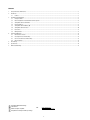
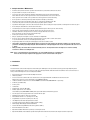
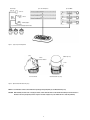
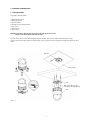
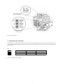
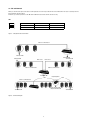
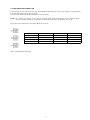
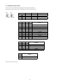
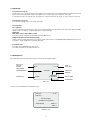
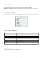
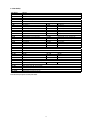
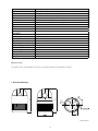
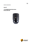
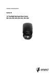
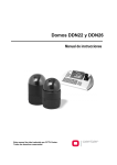
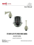
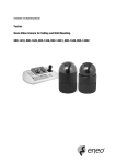
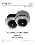
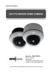
Quick Installation Guide
Fastrax III
1/4” Day/Night Dome Camera, PTZ, 22x
EDC-3222
Contents
1.
Safety Instructions / Maintenance.................................................................................................................................................................................... 3
2.
Introduction..................................................................................................................................................................................................................... 3
2.1
3.
Installation and Configuration........................................................................................................................................................................................... 5
Features.............................................................................................................................................................................................................. 3
3.1
Package Contents............................................................................................................................................................................................... 5
3.2
Basic Configuration of Fastrax III Dome Camera System...................................................................................................................................... 6
3.3
Setting Dome Camera Termination...................................................................................................................................................................... 7
3.4
Fail-safe Network................................................................................................................................................................................................ 8
3.5
Setting Dome Camera Address (ID)...................................................................................................................................................................... 9
3.6
Setting Dome Camera Protocol . ....................................................................................................................................................................... 10
3.7
Connections...................................................................................................................................................................................................... 11
3.8
Getting Started.................................................................................................................................................................................................. 11
4.
Program and Operation.................................................................................................................................................................................................. 12
4.1
Dome Camera Selection.................................................................................................................................................................................... 12
4.2
Accessing On-Screen Menu Utility..................................................................................................................................................................... 12
4.3
How to control On-Screen Menu Utility.............................................................................................................................................................. 12
4.4
More Information............................................................................................................................................................................................... 12
5.
Short Cut Key................................................................................................................................................................................................................. 13
6.
Specifications................................................................................................................................................................................................................ 14
7.
Dimensional Drawings................................................................................................................................................................................................... 15
Komplette Betriebsanleitung
Full Manual
Mode d’emploi complète
⇒
www.videor.com
www.eneo-security.com
Kompletna Instrukcja instalacji i obsługi
1. Safety Instructions / Maintenance
• Read these safety instructions and the operation manual first before you install and commission the camera.
• Keep the manual in a safe place for later reference.
• Protect your camera from contamination with water and humidity to prevent it from permanent damage. Never switch the camera on when it gets wet. Have it checked at an authorized service center in this case.
• Never operate the camera outside of the specifications as this may prevent the camera functioning.
• Do not operate the cameras beyond their specified temperature, humidity or power ratings.
• Operate the camera only at a temperature range of 0°C to +50°C and at a humidity of max. 90%.
• To disconnect the power cord of the unit, pull it out by the plug. Never pull the cord itself.
• Pay attention when laying the connection cable and observe that the cable is not subject to heavy loads, kinks, or damage and no moisture can get in.
• Do not attempt to disassemble the camera board from the dome.
• The warranty becomes void if repairs are undertaken by unauthorized persons. Do not open the camera housing.
• Never point the camera towards the sun with the aperture open. This can destroy the sensor.
• Installation, maintenance and repair have to be carried out only by authorized service centers.
Before opening the cover disconnect the unit from mains input.
• Contact your local dealer in case of malfunction.
• Only use original parts and original accessories from Videor E. Hartig GmbH.
• Do not use strong or abrasive detergents when cleaning the dome. Use a dry cloth to clean the dome surface.
In case the dirt is hard to remove, use a mild detergent and wipe gently.
• All openings provided in the housing for assembly purposes must be closed and/or sealed.
•The installer is responsible for ensuring that the degree of protection as per the technical specifications is upheld, e.g. by using all enclosed
gasket seals and O-rings, by waterproofing the cable exits with silicon or through laying the cable in such a way that the cable does not act as
a „gutter”.
• During assembly, care must be taken to ensure that existing seals are correctly inserted and are not displaced as a result of assembly.
You must not continue to use damaged seals.
NOTE: This is a class A digital device. This digital device can cause harmful interference in a residential area;
in this case the user may be required to take appropriate corrective action at his/her own expense.
2. Introduction
2.1 Features
The Fastrax III dome camera and the keyboard controller make up the building blocks for any surveillance/security system. Using multiple Keyboard Controllers and multiple dome cameras, no place is too large for monitoring. Extensible and flexible architecture facilitates remote control functions for a
variety of external switching devices such as multiplexers and DVRs.
• Built-in optical power zoom camera with True Night Shot function
• 240 Preset positions.
• 8 Tours consist of Preset, Pattern, Auto-Scan and other Tours can be programmed with over 300 functions and Preset location. While moving, each Preset scan can be watched in smooth Vector Scan mode.
• 16 Auto Scans with the normal, the vector, and the random mode and the Endless Auto-Pan with 13 speed steps
• 8 Patterns (up to 500seconds)
• 8 Privacy zones
• 16 Area Titles
• 8 Alarm inputs / 4 Aux outs (NC & NO)
• Variable speed from 0.1°/sec to 380°/sec
Three Variable speed (SLOW, NORMAL, TURBO). Turbo speed is Max 380°/sec with CTRL key pressed
• Pan / Tilt speed is inversely proportional to the zoom ratio with the option.
• Maximum speed is 380°/sec when preset command
• Auto Calibration from 0.1° to 6° (Tilt range is 0° to 180°)
• Programmable user preferences (alarm, preset, title, etc.)
• 180° Digital Flip or 90° Auto Flip depended on the model
• Up to 999 selectable camera addresses (3999 by software setting)
• Multi-Language Menu Display, Password Confirmation
• Function Run Menu using DVR without function key (Pattern, SCAN, ...)
• Built-in RS-485/422 receiver driver
• Optional Clear bubble with black liner (shelter) for concealing the camera
• Optional Tinted Bubble, Indoor & Outdoor pendant housing with heater & blower, Indoor Flush mount, Parapet mount & Roof Top mount
Alarm Input
(up to 8)
Alarm Output
(up to 4)
up to 255 multiplexers
up to 99 DVRs
<Sensor>
<Siren>
<Flashing light>
up to 254 cameras including 64 alarm modes
Figure 1 - Typical System Configuration
push
bubble ring ass’y
remove camera window
screw
push
Remove window
Assemble bubble ring ass’y
Figure 2 - Optional Assemble bubble ring ass’y
NOTE: It is recommended to remove camera window for improving picture quality when you assemble bubble ring ass’y.
CAUTION: When installing a Fastrax dome on a high pole outside, caution should be taken to avoid vibration and shaking of Fastrax dome due to
windload or shock of passing heavy vehicles. If pole is not stable enough, it may cause malfunction in accurate tilt positioning.
3. Installation and Configuration
3.1 Package Contents
The package contains the following:
1x Fastrax III (Dome Camera)
1x Bubble ring (optional)
1x Instruction manual
3x Assembly screws for attaching Fastrax III
3x Plastic anchor
1x 10Pin Connector
2x 12Pin Connector
CAUTION: B
e sure to have caution labels (E version only) on both body and base of the camera.
Different version will not support alarm input and output.
The dome camera is for use in surface mounting applications and the mounting surface should be capable of supporting loads up to 4.5kg.
The dome camera’s base should be attached to a structural object, such as a hard wood, wall stud or ceiling rafter that supports the weight of the dome
camera.
Cable entry
Surface (ceiling)
Unlock
Lock
Base
Align extruded tap in the base to the keyhole on the PCB in the body
Body
Lock
Figure 3 - Installation
3.2 Basic Configuration of Fastrax III Dome Camera System
RS485(+)
RS485(-)
J-Box
DOME1 +
DOME1 -
Dome
RX+(TX+)
RX-(TX-)
Power
24VAC
STP AWG #24
Alarm output
1 ~ 2
Sensor
Alarm input
up to 8
Alarm input
1 ~ 4
Power
24VAC
BNC
Dome1+
Siren
Dome1–
Light
Alarm output
up to 4
Alarm output
3~4
Alarm input
5~8
RS-485
Half Duplex mode: RX+(TX+), RX–(TX–)
Monitor
RS-422
Simplex mode: (RX+), (RX–)
Duplex mode: RX+(TX+), RX–(TX–), (RX+), (RX–)
Rear
Rear
Master Keyboard controller
Slave Keyboard controller
Figure 4 - Basic installation diagram
The dome camera must be installed by qualified service personnel in accordance with all local and federal electrical and building codes. The system should be installed according to Figures 4 through 9.
SW1: Termination switches
SW2: Fail-Safe Network
Addresses (ID) and protocol selection switches
Figure 5 - Layout of Switches
3.3 Setting Dome Camera Termination
The device which is connected at end of line, whether it be a dome camera or keyboard controller, must have the cable for communication terminated by
setting the appropriate DIP switch. Without proper termination, there is potential for control signal errors. Total length of the cable for communication should
not exceed 1.2km.
SW1
ON
1 2
SW1
1
2
Terminated
ON
ON
Not terminated
OFF
OFF
Figure 6 - Setting Dome Camera Termination
3.4 Fail-safe Network
When you control the dome by the other device not own keyboard, some error may be existed in the serial communication. The reason is caused by the other
device without the fail-safe network.
At this time, you solve the problem to set this DIP switch to ON of the nearest dome from the other device only.
SW2
ON
1 2
SW2
1
2
ON
PULL-UP
PULL-DOWN
OFF
NONE
NONE
Figure 7 - Setting Dome Camera Termination
Cable for communication
Termination ON
Termination ON
Termination ON
Termination ON
Dome 1 Port
Dome 2 Port
Cable for communication
Cable for communication
Termination ON
1.2km
Repeater/Splitter
1.2km
Cable for communication
Input termination ON
Output termination ON
Termination ON
Figure 8 - Termination Diagram
Termination ON
3.5 Setting Dome Camera Address (ID)
To prevent damage, each dome camera must have a unique address (ID). When installing multiple dome cameras using a multiplexer, it is suggested that the
dome camera address matches the multiplexer port number.
If you wan to set the address more than 999, you should connect the service provider.
Example: Port 1 = Dome 1, Port 2 = Dome 2 ... Port 16 = Dome 16. If more than 16 dome cameras are installed using two or more multiplexers, ID of the dome camera should be ID of MUX x No. of camera IN. (e.g. multiplexer ID= n, Camera IN= m then ID of Dome =16x (n-1) +m)
Refer to Figures 4-5 for setting the dome camera address (ID) and protocol selection.
Dome ID
S3
S2
S1
1
0
0
1
2
0
0
2
…
…
…
…
999
9
9
9
Figure 9 - Setting Dome Camera Address (ID)
3.6 Setting Dome Camera Protocol
If a dome camera is to be installed with a Fastrax keyboard controller, select the default protocol.
Consult service personnel if a dome camera is installed with device other than a keyboard controller.
S/W
D1
D2
D3
D4
S4-1
S4-2
S4-3
S4-4
On
Off
Function
Enable
PAL
Disable
NTSC
RS-422
RS-485
Alarm
NTSC/PAL
(Reserved)
RS-422/RS-485
D5
D6
D7
D12
S5-1
S5-2
S5-3
S6-4
Off
Off
Off
Off
On
On
On
On
Off
Off
Off
Off
Off
Off
On
On
Off
Off
On
On
Off
Off
On
On
Off
On
Off
On
Off
On
Off
On
Off
On
Off
On
Off
Off
Off
Off
Off
Off
Off
Off
On
On
On
On
D8
S5-4
Off
Off
Off
Off
On
D9
S6-1
Off
Off
On
On
Off
D10
S6-2
Off
On
Off
On
Off
D11
S6-3
Off
On
Protocol
F2, F2E, Pelco-D, Pelco-P: Default
F2, F2E
Sensormatic RS-422
Pelco-D, Pelco-P
Vicon
Ernitec
(Reserved)
F2
Philips (Bosch)
(Reserved)
Dynacolor
(Reserved)
Baud Rate
2400 bps
4800 bps
9600 bps (Default)
19200 bps
38400 bps
Parity Bit
None
Even
Figure 10 - Protocol Selection Switches
10
3.7 Connections
• Connecting to the RS-485/-422
The dome camera can be controlled remotely by an external device or control system, such as a control keyboard, using RS-485 half-duplex, RS-422 full duplex or simplex serial communications signals. Connect Marked Tx+, Tx- to Tx+(Rx+) and Tx-(Rx-) of the RS-485 control system.
If control system is RS-422, connect Rx+(Tx+), Rx+ (Tx-) and Rx+, Rx- of the dome camera to Rx+, Rx- and Tx+, Tx- of the control device respectively.
• Connecting Video out connector
Connect the video out (BNC) connector to the monitor or video input.
• Connecting Alarms
AL1 to 8 (Alarm In)
You can use external devices to signal the dome camera to react on events. Mechanical or electrical switches can be wired to the AL (Alarm In) and GND (Ground) connectors. See Chapter 3 - Program and Operation for configuring alarm input.
GND (Ground)
NOTE: All the connectors marked GND are common.
Connect the ground side of the Alarm input and/or alarm output to the GND connector.
NC(NO)1 TO 4 (Normal Close or Normal Open: Alarm Out)
The dome camera can activate external devices such as buzzers or lights. Connect the device to the NC(NO) (Alarm Out) and COM (Common) connectors. See Chapter 3 - Program and Operation for configuring alarm output.
• Connecting the Power
Connect the power of 24VAC 850mA to the dome camera.
Use certified / Listed Class 2 power supply transformer only.
3.8 Getting Started
Once installed apply power to the dome camera. The dome camera will start a configuration sequence.
PRESET TITLE
AREA TITLE
FUNCTION
UNDER RUNNING
001
AF AE
CAMERA TITLE
EMPTY DATA
INFORMATION DISPLAY
STATUS of FOCUS and AE
CAMERA ID
ALARM:1
ALARM DISPLAY
DOMEID:0001
W->360.0,090.0
PAN & TILT ANGLE
VIEW DIRECTION
OSD Position
The dome can move the OSD position in the OSD position setup.
(AREA TITLE)
(FUNC TITLE)
(AF AE)
(CTRL KEY TO MOVE)
SAVE AND EXIT (ESC TO CANCEL)
(ALARM MESSAGE)
OSD Position Setup
11
(DOME ID...)
(ANGLE...)
4. Program and Operation
4.1 Dome Camera Selection
Before you program or operate a dome camera, you must select the dome camera by pressing the dome camera No. + CAM.
Example: Pressing 1, 0 and CAM key sequentially will select dome camera 10. The selected dome camera ID will be displayed on the LCD monitor of the
keyboard controller. 4.2 Accessing On-Screen Menu Utility
You can call up the On-screen menu utility on your monitor by pressing MENU key on the keyboard controller, the following On-screen menu utility will appear:
DOME MENU
AUTO SCAN
PRESET
TOUR
PATTERN
ALARM
AREA TITLE
PRIVACY ZONE
CAMERA
DOME SETUP
FUNCTION RUN
EXIT (ESC TO EXIT)
4.3 How to control On-Screen Menu Utility
Button
Function
MENU
Call on On-screen menu utility
Joystick up or down
Navigate through the menu items.
Joystick left or right or IRIS OPEN
Go into the sub-menu items.
Joystick left or right or Zoom handle twist or
Tele, Wide
Change value.
Enter the editing title mode.
CTRL + Joystick
Change value of angle.
IRIS OPEN
Enter the changing angle mode.
IRIS CLOSE
Exit the changing angle mode.
ESC
Escape (EXIT)
4.4 More Information
For more information, please see the Full Installation and Operating Manual.
12
5. Short Cut Key
Short Cut Key
PRST
TOUR
PTRN
SCAN
NO.+ PGM + PRST
Short Cut Key
1 + ON
2 + ON
3 + ON
4 + ON
7 + ON
8 + ON
9 + ON
10 + ON
11 + ON
12 + ON
13 + ON
14 + ON
15 + ON
100 + ON
101 + ON
102 + ON
103 + ON
104 + ON
105 + ON
150 + ON
151 + ON
152 + ON
153 + ON
154 + ON
155 + ON
250 + ON
888 + ENTER
999 + ENTER
Function
Pop up preset setup menu
Pop up Tour setup menu
Pop up Pattern setup menu
Pop up Auto Scan setup menu
Store the current view at the selected number
Function
Turn On Relay 1
Turn On Relay 2
Turn On Relay 3
Turn On Relay 4
Change FOCUS to AUTO
Change AE to AUTO
Change Night Shot to AUTO
Night Shot ON (go to the manual mode)
BLC ON (AE auto mode)
Digital Zoom ON (According to digital zoom setting)
Dome OSD ON
Dome Area Title Display ON
View Direction ON
Shutter speed auto
Shutter speed 1/4 (PAL 1/3) sec
Shutter speed 1/2 sec
Shutter speed 1 sec
WDR ON
Image Stabilizer ON
Image Flip ON
Origin Check
Place the camera in the 0° area horizontally.
Go to the slow speed mode
Display System Information
Flip the camera in the 180° area horizontally.
Set the dome ID up to 3999
Night Shot ON (in the global mode only)
Night Shot OFF (in the global mode only)
Short Cut Key
1 + OFF
2 + OFF
3 + OFF
4 + OFF
7 + OFF
8 + OFF
Function
Turn Off Relay
Turn Off Relay
Turn Off Relay
Turn Off Relay
Change FOCUS to manual
Change AE to manual
10 + OFF
11 + OFF
12 + OFF
13 + OFF
14 + OFF
15 + OFF
Night Shot OFF (go to the manual mode)
BLC OFF (AE auto mode)
Digital Zoom OFF
Dome OSD OFF
Dome Area Title Display OFF
View Direction OFF
104 + OFF
105 + OFF
150 + OFF
WDR OFF
Image Stabilizer OFF
Image Flip OFF
153 + OFF
Go to the normal speed mode
Some function may not operate according to the model.
13
6. Specifications
Type
EDC-3222
Art. No.
74193
Series
eneo Fastrax III
System
day&night
Video standard
CCIR/PAL
Sensor size
1/4”
Imager
CCD, Sony ExView HAD Interline Transfer
Active picture elements
795(H) x 596(V) pixels
Horizontal resolution
580 TVL
Synchronization
Internal/AC line lock, phase adjustment via remote control
Signal-to-noise ratio
50dB (AGC OFF)
Sensitivity (at 50% video signal)
1.0 Lux, (colour), 0.1Lux (B&W) at F1.2 (measured)
Automatic electronic shutter (ESC)
yes
Manual electronic shutter (MES)
1/50 ~ 1/100,000sec.
Low speed shutter
yes
Digital Noise Reduction (DNR)
yes
Backlight compensation
BLC
Wide Dynamic Range (WDR)
WDR
White balance
modes: manually, automatic, indoor, outdoor, ATW, AWC
Aperture Correction (APC)
horizontal, vertical
Flickerless function
yes
IR cut filter
switchable
Privacy zones masking
8 zones masking with block or video OFF option
Menu languages
German, English, French, Spanish, Italian, Portugese, Polish
OSD function control
day&night, AGC, BLC, AWB, iris, MOD, flickerless, digital zoom, digital noise reduction (DNR), WDR, shutter mode
Text display
16 character label
Activity detection
yes
Mirror function
vertical
Digital zoom
16x
Analysis functions
activity detection
Lens type
zoom
Zoom factor
22x
Focal length
3.9mm - 85.8mm
Horizontal angle of view
49.5° - 2.46°
MOD (Minimum object distance)
1.0 m
Aperture range (F)
F1.6 (3.6) ~ F130
External adjustments
ID, Baud rate, Termination and protocol type switches
Video outputs
composite (CVBS), 1Vp-p, (C)VBS, 75ohms, BNC
Alarm inputs
8
Alarm outputs
4
Speed (manual control)
380°/sec.
Speed range at manual control (pan)
0.1° ~ 380°/sec. (proportional to zoom)
Speed range at manual control (tilt)
0.1° ~ 200°/sec. (proportional to zoom)
Preset speed
380°/sec.
Rotation range
360°
Tilt range
-10° ~ +190° (Digital Flip)
Backlash
0.2°
14
Patterns
8 patterns up to 500sec.
Tours
up to 8 programmable guard tours, consisting of 42 presets each and up to 12 character title display
Autoscan
16 User programmable auto scans with 13 selectable speeds and 12 character title display
Proportional pan and tilt
continually decreases pan and tilt speeds in proportion to depth of zoom
Auto flip function
180° digital flip (turns the video output from the camera upside down and reverses it horizontally)
Home position
included
Presets
240 presets with camera status (12-character title display)
Illumination
no
Serial interfaces
RS-422, RS-485
Housing material
plastic
Bubble
4.9” (125mm), clear acrylic plastic
Colour (bubble)
clear
Colour (housing)
black
Mounting
ceiling mount, housing assy
Supply voltage
24VAC, (18 ~ 30VAC), 50/60Hz
Power consumption
20W
Temperature range (operation)
0°C ~ +50°C
Vandalism resistant
no
Protection rating
n/a
Weight
1.25kg
Parts supplied
camera, manual
Certificates
CE
Optional Accessories
The optional accessories currently available can be found on our Homepages: www.videor.com and www.eneo-security.com.
199
202
7. Dimensional Drawings
R2.3
R5
45
Dimensions: mm
15
eneo® is a registered trademark of Videor E. Hartig GmbH
Exclusive distribution through specialised trade channels only.
VIDEOR E. Hartig GmbH
Carl-Zeiss-Straße 8 · 63322 Rödermark/Germany
Tel. +49 (0) 6074 / 888-0 · Fax +49 (0) 6074 / 888-100
Technical changes reserved.
www.videor.com
www.eneo-security.com
© Copyright by VIDEOR E. Hartig GmbH 05/2012
16