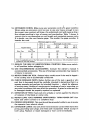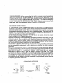
1
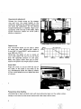
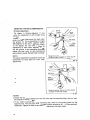
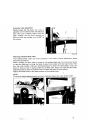
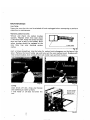
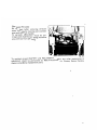
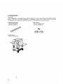
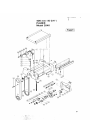
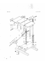
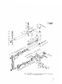
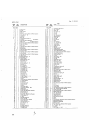
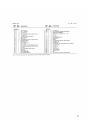
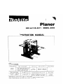
Planer
400 mm (15-3/4") MODEL 2040
INSTRUCTION MANUAL
SPECIFI CAT IONS
396 mm
I1 5~518")
1 mm 11/32")of stock wtdth
over 304 mmll 1-314")
3 mm 1118"l o f stock width
under 150 mm 15-718")
Max. srock height
12.7mm - 1 9 5 m m
1112" - 7-518")
No load speed
6,500
,,,,In,
9 m/mm
129 5 ftimin.1
396 mm x 600 nim
115 5/8" x 23 5/8"1
Overall dimenslons (W x
L
x
HI
570 mm x 1,025111111 x 715 r n n l
122 112" x 40.318'' x 28 118"l
2
Net weight
115 k g
(254 Ibsl
For Your Own Safety Read Instruction
Manual Before Operating Planer
GENERAL SAFETY PRECAUTIONS
(For All Tools)
1. KNOW YOUR POWER TOOL. Read the owner's manual carefully. Learn the
tools applications and limitations, as well as the specific potential hazards
peculiar t o it.
2. KEEP GUARDS IN PLACE and in working order.
3. REMOVE ADJUSTING KEYS AND WRENCHES. Form habit of checking t o
see that keys and adjusting wrenches are removed from tool before turning
it on.
4. KEEP WORK AREA CLEAN. Cluttered areas and benches invite accidents.
5. DON'T USE IN DANGEROUS ENVIRONMENT. Don't use power tools in damp
or wet locations, or expose them t o rain. Keep work area well lighted.
6.KEEP CHILDREN AWAY. All visitors should be kept safe distance from work
area.
7. MAKE WORKSHOP KID PROOF with padlocks, master switches, or by
removing starter keys.
8. DON'T FORCE TOOL. It will do the job better and safer at the rate for which
it was designed.
9. USE RIGHT TOOL. Don't force tool or attachment t o do a job for which it
was not designed.
10. WEAR PROPER APPAREL. Wear no loose clothing, gloves, neckties, rings,
bracelets, or other jewelry which may get caught in moving parts. Nonslip
footwear is recommended. Wear protective hair covering t o contain long hair.
11. ALWAYS USE SAFETY GLASSES. Also use face or dust mask if cutting operation is dusty. Everyday eyeglasses only have impact resistant lenses, they
are NOT safety glasses.
12. SECURE WORK. Use clamps or a vise t o hold work when practical. It's safer
than using your hand and it frees both hands t o operate tool.
13. DON'T OVERREACH. Keep proper footing and balance at all times.
14. MAINTAIN TOOLS WITH CARE. Keep tools sharp and clean for best and
safest performance. Follow instructions for lubricating and changing accessories.
15. DISCONNECT TOOLS before servicing; when changing accessories such as
blades, bits, cutters, and the like.
"
Total length of cord in feet
Volts
12OV
240V
Ampere Rating
I
More Than
Not
More Than
0
6
10
12
6
10
12
16
25ft.
5011.
50ft.
100 ft.
100ft.
200 ft.
150 ft.
300 ft.
AWG
18
18
16
14
16
16
16
12
16
14
14
12
14
12
Not Recommende
'Only the applicable parts of the Table need to be included. For instance. a 120-volt product need no
include the 240-volt headina.
17. REDUCE THE RISK OF UNINTENTIONAL STARTING. Make sure switch
in off position before plugging in.
18. USE RECOMMENDED ACCESSORIES. Consult the owner's manual fc
recommended accessories. The use of improper accessories may cause ris
of injury t o persons.
19. NEVER STAND ON TOOL. Serious injury could occur if the tool is tipped c
if the cutting tool is accidentally contacted.
20. CHECK DAMAGED PARTS. Before further use of the tool, a guard or otht
part that is damaged should be carefully checked t o determine that it wi
operate properly and perform its intended function
check for alignmer
of moving parts, binding of moving parts, breakage of parts, mounting, an
any other.conditions that may affect its operation. A guard or other part thc
is damaged should be properly repaired or replaced.
-
21. DIRECTION OF FEED. Feed work into a blade or cutter against the directio
of rotation of the blade or cutter only.
22. NEVER LEAVE TOOL RUNNING UNATTENDED. TURN POWER OFF. Don
leave tool until it comes t o a complete stop.
23. PROPER GROUNDING. This tool should be grounded while in use t o protec
the operator from electric shock.
24. EXTENSION CORDS: Use only three-wire extension cords which have threr
prong grounding-type plugs and three-pole receptacles which accept th
tool's plug. Replace or repair damaged or worn cord immediately.
I
3LTAGE WARNING: Before connecting the tool t o a power source (receptacle,
Itlet, etc.) be sure the voltage supplied is the same as that specified on the
m e p l a t e of the tool. A power source with voltage greater than that specified
)r the tool can result in SERIOUS INJURY t o the user
as well as damage t o
le tool. I f in doubt, DO NOT PLUG IN THE TOOL. Using a power source with
oltage less than the nameplate rating is harmful t o the motor.
-
;ROUNDING INSTRUCTIONS
\LL GROUNDED, CORD-CONNECTED TOOLS: In the event of a malfunction or
Breakdown, giounding provides a path of least resistance for electric current t o
educe the risk of electric shock. This tool is equipped with an electric cord having
an equipment-grounding conductor and a grounding plug. The plug must be
ilugged into a matching outlet that is properly installed and grounded in aczordance w i t h all local codes and ordinances.
Do not modify the plug provided-if it will not f i t the outlet, have the proper
outlet installed by a qualified electrician.
Improper connection of the equipment-grounding conductor can result in a risk
of electric shock. The conductor with insulation having an outer surface that
is green w i t h or without yellow stripes is the equipment-grounding conductor.
If repair or replacement of the electric cord or plug is necessary, do not connect
the equipment-grounding conductor t o a live terminal.
Check w i t h a qualified electrician or serviceman if the grounding instructions
are not completely understood, or if in doubt as t o whether the tool is properly
grounded.
This tool is intended for use on a circuit that has an outlet that looks like the
one illustrated in Figure A. The tool has a grounding plug that looks like the plug
illustrated in Figure A. A temporary adapter, which looks like the adapter
illustrated in Figure B and C, may be used to connect this plug t o a 2-pole
receptacle as shown in Figure B if a properly grounded outlet is not available.
The temporary adapter should be used only until a properly grounded outlet can
be installed by a qualified electrician. The green-colored rigid ear, lug, etc.
extending from the adapter must be connected t o a permanent ground such as
a properly grounded outlet box.
GROUNDING METHODS
FIG. A
FIG.
B
~
FIG. C
Grounding
Groundibg Pin
Munl
- I
. . ..
....
.
. .. ... ........ ,
......
.. .....i'.
...
:: (;;!..
.
. . :
......
.
. ... . . . .
,...
?. ::i 5 .
.. ,I ... ... ,.
"I
ADDITIONAL SAFETY RULES
1. Wear eye protection.
2. Never perform planing operation w i t h drive guard removed.
3. Do not perform planing operations on material shorter than (a dimension
equal t o the cutter head length plus 2 inches), narrower than 314 inch, or
wider than (the cutter capacity in inches) or thinner than 1/2 inch.
4. Don't use the tool in presence of flammable liquids or gases.
5. Handle the blades very carefully.
6. Check the blades carefully for cracks or damage before operation. Replace
cracked or damaged blades immediately.
7. Be sure the planer blade installation bolts are securely tightened before
operating.
8. Sharpen both blades evenly, or replace both blades or both cutterhead covers
at the same time.
9. Remove nails and clean the workpiece before cutting. Nail, sand or other
matter can cause blade damage.
10. Make sure the blade is not contacting workpiece before the switch is turned
on.
11. Wait until the blades attain full speed before cutting.
12. Keep hands away from rotating parts.
13. Don't back the workpiece toward the infeed table.
14. Two or more pieces of narrow but similar thickness stock can be passed
through the auto-planer side by side.
However, allow some spacing between the stock t o permit the feed rollers
t o grip the thinnest piece.
Otherwise, a slightly thinner piece could be kicked back by the cutterhead.
15. Stop operation immediately if you notice anything abnormal.
16. Always switch off and wait for blades t o come t o a complete stop before
adjusting any parts, cleaning out chips or approaching the blade.
17. Never stick your finger into the chip chute. Chute may jam when cutting
damp wood. Turn off the planer and then clean out chips w i t h a stick.
18. Don't touch blades right after operation, they may be extremely hot and could
burn your skin.
19. Don't abuse cord. Never yank cord to disconnect from receptacle. Keep cord
from heat, oil and sharp edges.
SAVE THESE INSTRUCTIONS.
Dimensional adjustment
Release the thumb screw on the stopper
ring and turn the crank handle to the
clockwise, aligning the indicator plate until
the scale bar graduation for the desired
finished dimension i s reached. Algin your
workpiece with the top of the table. (One
handle revolution makes for 3 mm (1/8")
ascent or descent.)
Fig. 1
Gauge height shows the amount of cut
Depth of cut
The maximum depth of cut with a piece
of wood less than 150 mm (6")wide i s
3 mm (1/8") (1mm (3/64")with a width of
over 300 mm ( 1 2")).
Determine the depth of cut in terms of
your stock width. Do not try to cut more
than the specified amount in one pass.
Make two passes rather than put an overload on the planer that might cause trouble.
OEP
118I3 mml
3m4"
11 mml
WIDTH
c'
1I'
16-314"
1150 mml
1300 mml
1400mml
Stock feed
Align the stock to be cut with the top of
the table. I f the stock is too thick to be
cut, immediately lower the table by means
of the crank handle so as to reduce the size
of the cut.
Fig.
Precautions when feeding
*Attempting to feed outsized stock will cause abnormal wear on the rubber rollers.
Keep on the level so that cutter action and roller wear will be even.
6
:
-~
~
Return
Returning cut stock back to the front side
is very easy if you use the convenient return rollers on top.
Return rollers
Stopper regulatingdepth
Numerous workpieces can be planed to the
same thickness very simply just by setting
the stopper ring to the desired dimension.
Do not crank the handle so hard that you
force the stopper ring to move.
Fig. 4
Key safety switch
This machine can only be switched on after the key i s inserted in the switch. The key can
be removed with the switch in the "ON" condition, and the tool may be switched off
without the key. When.unattended, the machine should be both "OFF" and unplugged.
7
CHANGING CUTTER KNIVES
First, unplug the planer from the power source so as to prevent any mishap.
Removal
a. Loosen the pan hd. screws on the set plates with the (+) screwdriver, then swing the set
plates.
Remove the chip guard, lift the lever and swing it a full 180 degrees; then use the knob
on the belt guard side to align the cutter drum as shown in Fig. 6.
Next, release the lever to make the drum stationary.
Fig.
b. Remove the 8 hex bolts with the socket wrench provided, then take off the drum
cover (cutter retaining plate). Use the end of the socket wrench handle to push the
cutter out slightly. Raise the lever, once more making the drum stationary a t the position seen in Fig. 7; then remove the cutter knife.
Cutter knife
Drum cover
Fig. 7
CUTTER KNIFE INSTALLATION &
HEIGHT ADJUSTMENT
a. At the position shown in Fig. 7, insert
the knife so the holes are aligned with
those on the drum. Set the wooden
levellers on each end of the knife edge
and press down on both ends until the
main frame surface is contacted.
The levellers should be pressed down
just above the hex bolt holes on either
end.
b. Fix the cutter drum a t the position
shown in Fig. 6, attach the durm cover
and fasten securely the hex bolts.
Tightening a l l bolts fully in order may
cause the knife to move. A t first,
tighten bolts gradually and evenly before applying the final tightening torque.
Fig. 11
c. Secure the lever a t the position you
found it a t when the chip guard was
raised, then set the lever on top (see
right), pressing down very gently and
turning the cutter drum in the arrow
direction. The leveller should move the
same amount when placed over either
end of one and the same knife (i.e., approx. 5 - 6 mm (3/16”- 1/4”)). After
adjusting knife height on both knives,
replace chip guard as before. Replace
guards after completing adjustments.
Auto-planer guard (chip cover) should
be secured a t original position.
5-6”
(3/16‘- 1/4“)
Press
li
Fig. 12
9
ADJUSTING VARIOUS COMPONENTS
Bed roller adjustment
(The planer i s factory-adjusted. If you
notice the adjustment is off, kindly do as
f 01I ows.)
Loosen the pan head screw for each roller
under the table. Use a screwdriver to rotate
the groove on the roller adjuster within
180 degrees on the four roller axes. Refer
to the figures for the correct range of
adjustment of each roller adjuster. Rotating the groove in the ascending direction
causes the bed roller to rise; turning the
groove down causes the bed roller to lower.
NOTE :
The above adjustment procedure should be
Range of groove rotation on roller adjuster
to adjust height o f bed roller (left).
Range of groove roation on roller adjuster
t o adjust of bed roller (right).
Fig. 11
Caution
Unless the two groove positions on the one roller face the same direction, the stock may
be twisted to the left or right.
I f the rollers protrude too much, notching may result in the surface planed on the
opposite end. The protrusion from the table surface should be 0.1 - 0.3mm (postcard
thickness). Tighten the small screw when the adjustment has been made.
Extension roller adjustment
Gently loosen the hex bolts, set a rule or
yardstick on the table surface and adjust so
that roller arm is slightly higher than the
table. Tighten the hex bolts securely so
that the roller arm surface is a t the 90" to
the column.
Fig. 11
Adjusting infeed/outfeed rollers
The infeed/outfeed rollers are factory adjusted. If the rollers require adjustment, please
follow this procedure :
Place a straight and.lever piece of wood on the outfeed table top. Turn the crank handle
to raise the table and to bring the piece of wood into contact with the main frame. Then
turn the crank handle a half-turn counterclockwise to lower the table slightly. Insert the
piece of wood so that it reaches under the outfeed roller. Adjust the right and left heighi
adjusting screws so that the outfeed roller contacts the piece of wood evenly.
Adjust the infeed roller in the same manner as the outfeed roller.
I
NOTE :
Turning the height adjusting screw one turn clockwise lowers the roller 3 mm (1/8").
MAINTENANCE
CAUTION :
Always be sure that the tool is switched off and unplugged before attempting to perform
inspection or maintenance.
Replacing carbon brushes
3emove and check the carbon brushes
egularly. Replace when they wear down
o the limit mark. Keep the carbon brushes
:lean and free to slip in the holders. Both
arbon brushes should be replaced a t the
ame time. Use only identical carbon
]rushes.
5
Limit
mark
Fig. II
nsert a minus screwdriver into the holes for carbon brush changeover on the base of the
daner. Remove the brush holder cap and take out the worn carbon brush. Replace with
new carbon brushes, then reinstall the brush holder caps and both holders.
Fig. 20
eaning
iways brush off dirt, chips and foreign
atter adhering to roller surfaces.
.e that water or oil does not enter the
mor.
Oil the contact
portion of the
I
Fig.
21
Lubrication (Periodic)
Oil the chain (after removing the chain
cover), the column moving parts (contact
areas) and the crank handle.
The periodic lubrication should be performed with machine oil. (Oiling should be
done with tool not operating.)
To maintain product SAFETY and RELIABILITY, repairs, any other maintenance or
adjustment should be performed by Makita Authorized or Factory Service Centers,
always using Makita replacement parts.
13
ACCESSOR I ES
CAUTION :
These accessories or attachments are recommended for use with your Makita tool specified in this
manual The use of any other accessories or attachments might present a risk of injury to persons.
The accessories or attachments hsould be used only in the proper and intended manner.
Replacement blades
0
400 mm (15-3/4”1
Part No. 731024-2
/
0
Planer stand
Part No. 122192-3A
c
14
Sprocket set
(For Low Speed Feed)
Part No. 191440-4
A&
; f i t
.
.
Mpy
400 mm (15-3/4")
12 '86 US
I
PLANER
Model 2040
15
Jan -08-'96
MODEL 2040
c
c
16
Us
17
MODEL 2040
I:.
,'"
May
$f,
DESCRIPTION
12-'86
DESCRIPTION
MACHINE
I
2
3
5
7
8
9
10
It
12
13
14
15
16
17
18
19
20
21
22
,
I
I
1
1
2
1
1
1
1
1
2
I
?
2
1
1
2
4
1
4
23
I
24
25
26
27
28
29
30
31
32
33
34
35
36
37
38
39
40
41
42
43
44
45
46
47
48
49
50
51
52
53
54
55
4
56
I
2
I
I
1
I
1
1
1
I
1
1
1
1
1
1
1
2
I
1
1
1
1
1
1
1
1
1
1
1
1
57
2
4
58
4
59
4
4
60
61
62
63
64
1
4
4
1
65
4
66
67
68
69
70
71
72
73
74
4
4
1
1
1
I
1
1
1
- -
Chip Covpr
GB"q.
Main Frame
Switch
Pan Head Screw M5.12 IWith Washerl
Spmg Pm 4 18
Lever 5 0
Bush 10
ComprFsIlO" sprmg 1 I
Lock Pin
Pan Heed Screw M 5 r 2 0 IWith Washer1
Bell cover
Pan Head Screw M5x35 lWith Warhnrl
Pan Heed Sciew M 5 x I O IWOlh Washeil
Bell covrr stay
Scale Bar
Pan Head Screw M 5 r 1 4 IWith Washerl
RlWf 0 5
Name Plate
Pen Heid Screw M 5 r 1 4 lWilh Warheil
Plarrure Plate
Pan Head Screw M5.14 W i t h Washer)
Chip Bleaker
Pen Head Screw M 5 r l O IWilh Washer)
Chain Cover
Remnmg Rtng S I 2
Flat Weshet 1 2
Tension Roller
Needle Bearing 12 12
Flat Washer 1 2
Tenslo" Cole
Ratasnmg Rmg S 12
Sorocket 15
Gear Housing
Flat W81her 12
Gear Complete 1 3 61
F l a Waihar I 2
Flat Washer 14
Helical Gear 69
Woodrvll K e y 4
Diiving Shaft
Flat Warher 14
Flat Washer 10
Gear Complete 11 73
Flat Washer 10
Hook
Pan Head Screw M 5 r 3 5 IWith Warherl
Tenslo" s p m g 8
Te"Sl0"W
Cham Cover Core
nlng 50
Ring 6
Wmg Bolt M 6 r 2 5
Extension Roller 25 ~ 3 9 5
Roller Arm
Stop Ring E 9
Hex Boll Max25 IWith Washeel
SIOP
Flat Washer 8
IndiCaIor Plate
Hex Bolt M8-25 IWith Washcil
Flat Washer 8
Table
Spring Washer 6
Hex Nut M 6
Pan Head Screw M6r50
Hex Not M I 2
Spring Wayher I 2
Flat Waihrr I 2
Rmq 46
Handle Supgorlrr
Woodrull K e y 4
Handle Shalt
88
89
90
91
92
93
94
95
96
97
98
99
00
01
02
03
04
05
06
07
08
09
IO
11
I2
13
14
15
16
17
18
19
20
21
22
23
24
I
1
1
1
1
1
I
I
1
1
1
1
4
4
2
4
4
1
4
1
1
5
1
1
4
8
4
4
2
2
2
2
2
2
2
2
2
4
2
2
2
2
2
2
2
2
I
2
2
4
26
27
28
29
I
1
I
2
16
30
4
31
32
33
34
35
36
37
38
8
2
39
4
25
40
11
12
13
14
15
16
,
14
Comp,e.l,a" sprmg 19
Hex Nul M I 0
Handle 175
Flat Washer 10
GVP 3 0
Bolt M I 0
Hex Bolt M a x 2 0
WOodrUll Key 4
Screw M24
c a p 34
Fell Rmq 34
88%
Flat Warher 1 1
Her 8011M10x70
Stable Base
Snap Ring 55
Bellow.
50181 Pm 3 25
snap Rmg 55
Straight Bevel Gear 16
Thrust Needle Bearing 1528
Pan Head Screw M6x3O IWith Washer1
Slraighl Bevel Gear 16
Rslalnmg Ring
I5
s-
COlUm"
Sprmg Pm 8 60
Felt Ring 60
Cao 60
Plana Bcarlng 10
Roller 32 - 353
Plane 8Fall"g 10
Adwit Screw M 2 7
Mete1 Holder
Pm 10
comprerrmn S O l W 14
Plane 8"
17
Metal C o w L
Pan Head Screw M 5 r 1 4 lWith Washerl
Roller 8 5 - 4 0 0
Woodrull Key 4
Cwnwersm S w m g 14
Pm 1 0
Mew Holder
Ad1u.l Screw M 2 7
Sprockst I 5
Retaining Ring S- 12
Cham 3 5 - 6 4
Plans 8earmg 17
Metal Cover S
Pan Head Screw M5x14 lWilh Washerl
Cord
Cord Guard
Sllam Rrlml
Pen Head SCTEWM4114 IWiIh Wa3hcrl
Hex Flange Head Bolt M a x 3 0
Dium Covet 4 0 0
Pan Head Screw MSx12 IWiIh Washer1
Blade Holder 4W
1
Hex Bolt M5x45
I
1
I
1
5pimg Washer 5
H~IIc~
Gear
I
15
1
I
1
I
2
1
1
1
- -
1
18
75
76
77
78
79
80
61
82
83
84
85
86
87
Ball 8aarmg 6204LLB
Drum
Kcv 5
Countersunk Head Screw M5r16 IWith Washer)
Besrmg Retainer 57
Pall Bearing 6204LL8
3ea.tng cover
'an Head Screw M5x20 IWiIh Warherl
d Pulls" 9 8 3
(nob 4 0
'oly v Bell 9 1143
US
MODEL 2040
Jan -08--'96
US
EDDESCRlPTlDN
MACHINE
__
147
148
149
150
151
152
153
154
155
156
157
158
159
160
161
162
1
1
1
2
1
1
I
1
2
2
2
2
1
I
1
1
2
163
I64
165
166
1
2
167
1
I
Hex Nul MB
Spring Washer 8
Flat Warher 8
P m Herd Screw M6.18 IWllh Washer1
Trnrlon mate
Cap Square NeLk Bolt Max35
Motor Housing
Rear Cover
Pan Head Screw M5.12 IWilh Warherl
I n ~ ~ l a i i oWashri
n
Cdibon Brush
Brush Holder Cap
Strain R e l d
Pan Head Screw M 5 x 1 0 IWilh Washell
Pan Head Screw M5x30 lWilh Warherl
P,DleC,Dl
Hex Bolt M8.30 (With Washer1
m y e PI"
Stop Ring E 15
FIELD ASSEMBLY
Ball Bearing 6200LLB
168
1
169
2
Dust Seal 1 0
Pan Heed Screw M5195 IWilh Warherl
I70
1
ARMATUAE ASSEMBLY
IWilh Iten> 167 168 LL 1 7 0
I71
172
173
174
175
176
177
I78
179
1BO
1
Fan 92
Dust Seal 12
BAII nearnng 6 2 0 1 ~ ~ 8
Rubber Pin 6
8iackeI
P m Head Screw M5r25 IWith Washer1
v PUllSV 9 - 35
Flat Washer 7
Countorsunk Head Screw M5r16 lWilh Washer1
Flat warhsr 18
Leal spnng
set Plate
1
1
1
1
4
1
1
I
I
900
901
903
2
904
I
905
1
906
908
-
1
1
1
2
-
1731
Switch Plale
Swtich Piotector
S w w h Cover
Kev
Pan Head Screw M5x14 lWilh Warhell
19
e
MAKnA LIMITED ONE YEAR WARRANTY
Warranty Policy
Fvery Makita tool is thorou ly inspected and tested before leaving the factory. It is warranted tu
he free of defects from w o r k a n s h i p and materials for the period of ONE YFAR from the date of
orignal purchase. Should 8ny trouble develop during this onc.year period. return the COMPLETE
tool, freight prepaid. lo one of Mnkitn's Factory or Authorized Service Centers. If inspection shows
the trouble is caused by defective workmanship or material. Makitn will repair for at our option.
replace) without chargc.
.
This Warranty does not apply where:
repairs have been made or attempted by others:
repairs are required because ofnormal wear and tear:
The tool has been abused, misused or improperly maintained:
alterations have been made t o the 1001.
IN NO EVFNT SHALL MAKITA BE LIABLE FOR ANY INDIRECT INCIDENTAL OR CONSEQUENTIAL DAMAGES FROM THE SALE OR USE O F THE P R O D k T . THIS DISCLAIMER
APPLIES BOTH DURING AND AFTER THE TERM O F THIS WARRANTY.
MAKITA DISCLAIMS LIABILITY FOR ANY IMPLIED WARRANTIES, INCLUDING IMPLIED
WARRANTIES O F "MERCHANTABILITY" AND "FITNESS FOR A SPECIFIC PURPOSE,"
AFTER THE ONE-YEAR TERM OF THIS WARRANTY.
This Warranty gives you specific legal rights. and you may also have other rights which vary from
stale l o state. Some stales do not allow the exclusion or limitation ofincidental or consequential
damages, so the above limitation or exclusion may not apply lo you. Some states d o not allow
limitation o n how long an implied warranty lasts, so the above limitation may not apply l o you.
Makita Corporation
3-11-8, Sumiyoshi-cho,
Anjo, Aichi 446 Japan
883106F069
PRINTED IN JAPAN
1996 - 2
N
-