1
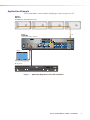
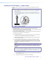
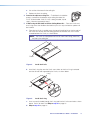
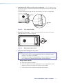
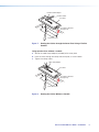
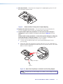
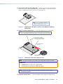
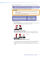
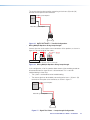
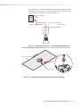
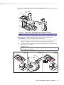
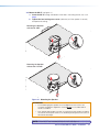
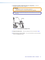
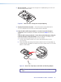
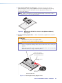
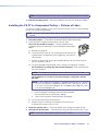
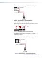
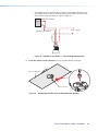
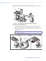
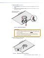
User Guide Speakers CS 3T and CS 120P CS 123T SpeedMount Ceiling Speaker System 68-2543-01 Rev. A 01 15 Safety Instructions Safety Instructions • English WARNING: This symbol, , when used on the product, is intended to alert the user of the presence of uninsulated dangerous voltage within the product’s enclosure that may present a risk of electric shock. ATTENTION: This symbol, , when used on the product, is intended to alert the user of important operating and maintenance (servicing) instructions in the literature provided with the equipment. For information on safety guidelines, regulatory compliances, EMI/EMF compatibility, accessibility, and related topics, see the Extron Safety and Regulatory Compliance Guide, part number 68-290-01, on the Extron website, www.extron.com. Instructions de sécurité • Français AVERTISSEMENT : Ce pictogramme, , lorsqu’il est utilisé sur le produit, signale à l’utilisateur la présence à l’intérieur du boîtier du produit d’une tension électrique dangereuse susceptible de provoquer un choc électrique. ATTENTION :Ce pictogramme, , lorsqu’il est utilisé sur le produit, signale à l’utilisateur des instructions d’utilisation ou de maintenance importantes qui se trouvent dans la documentation fournie avec le matériel. Pour en savoir plus sur les règles de sécurité, la conformité à la réglementation, la compatibilité EMI/EMF, l’accessibilité, et autres sujets connexes, lisez les informations de sécurité et de conformité Extron, réf. 68-290-01, sur le site Extron, www.extron.com. Sicherheitsanweisungen • Deutsch WARNUNG: Dieses Symbol auf dem Produkt soll den Benutzer darauf aufmerksam machen, dass im Inneren des Gehäuses dieses Produktes gefährliche Spannungen herrschen, die nicht isoliert sind und die einen elektrischen Schlag verursachen können. VORSICHT: Dieses Symbol auf dem Produkt soll dem Benutzer in der im Lieferumfang enthaltenen Dokumentation besonders wichtige Hinweise zur Bedienung und Wartung (Instandhaltung) geben. Weitere Informationen über die Sicherheitsrichtlinien, Produkthandhabung, EMI/EMF-Kompatibilität, Zugänglichkeit und verwandte Themen finden Sie in den Extron-Richtlinien für Sicherheit und Handhabung (Artikelnummer 68-290-01) auf der Extron-Website, www.extron.com. Instrucciones de seguridad • Español ADVERTENCIA: Este símbolo, , cuando se utiliza en el producto, avisa al usuario de la presencia de voltaje peligroso sin aislar dentro del producto, lo que puede representar un riesgo de descarga eléctrica. ATENCIÓN: Este símbolo, , cuando se utiliza en el producto, avisa al usuario de la presencia de importantes instrucciones de uso y mantenimiento recogidas en la documentación proporcionada con el equipo. Para obtener información sobre directrices de seguridad, cumplimiento de normativas, compatibilidad electromagnética, accesibilidad y temas relacionados, consulte la Guía de cumplimiento de normativas y seguridad de Extron, referencia 68-290-01, en el sitio Web de Extron, www.extron.com. Инструкция по технике безопасности • Русский ПРЕДУПРЕЖДЕНИЕ: Данный символ, , если указан на продукте, предупреждает пользователя о наличии неизолированного опасного напряжения внутри корпуса продукта, которое может привести к поражению электрическим током. ВНИМАНИЕ: Данный символ, , если указан на продукте, предупреждает пользователя о наличии важных инструкций по эксплуатации и обслуживанию в руководстве, прилагаемом к данному оборудованию. Для получения информации о правилах техники безопасности, соблюдении нормативных требований, электромагнитной совместимости (ЭМП/ЭДС), возможности доступа и других вопросах см. руководство по безопасности и соблюдению нормативных требований Extron на сайте Extron: www.extron.com, номер по каталогу - 68-290-01. Chinese Simplified(简体中文) 警告: 产品上的这个标志意在警告用户该产品机壳内有暴露的危险 电压, 有触电危险。 注 意: 产 品 上 的 这个 标 志 意 在 提 示用 户 设 备 随 附 的 用 户 手 册 中 有 重要的操作和维护(维修)说明。 关于我们产品的安全指南、遵循的规范、EMI/EMF 的兼容性、无障碍 使用的特性等相关内容,敬请访问 Extron 网站 www.extron.com,参见 Extron 安全规范指南,产品编号 68-290-01。 Chinese Traditional( ) 警告: 若產品上使用此符號,是為了提醒使用者,產品機殼內存在著 可能會導致觸電之風險的未絕緣危險電壓。 注意 若產品上使用此符號,是為了提醒使用者,設備隨附的用戶手冊中有重 要的操作和維護(維修)説明。 有關安全性指導方針、法規遵守、EMI/EMF 相容性、存取範圍和相關主題的詳 細資訊,請瀏覽 Extron 網站:www.extron.com,然後參閱《Extron 安全性 與法規遵守手冊》,準則編號 68-290-01。 Japanese 警告: この記号 が製品上に表示されている場合は、筐体内に絶縁されて いない高電圧が流れ、感電の危険があることを示しています。 注意: この記号 が製品上に表示されている場合は、本機の取扱説明書 に 記載されている重要な操作と保守(整備)の指示についてユーザーの 注 意を喚起するものです。 安全上のご注意、法規厳守、EMI/EMF適合性、その他の関連項目に ついては、エクストロンのウェブサイト www.extron.comより『Extron Safety and Regulatory Compliance Guide』(P/N 68-290-01) をご覧ください。 Korean 경고: 이 기호 가 제품에 사용될 경우, 제품의 인클로저 내에 있는 접지되지 않은 위험한 전류로 인해 사용자가 감전될 위험이 있음을 경고합니다. 주의: 이 기호 가 제품에 사용될 경우, 장비와 함께 제공된 책자에 나와 있는 주요 운영 및 유지보수(정비) 지침을 경고합니다. 안전 가이드라인, 규제 준수, EMI/EMF 호환성, 접근성, 그리고 관련 항목에 대한 자세한 내용은 Extron 웹 사이트(www.extron.com)의 Extron 안전 및 규제 준수 안내서, 68-290-01 조항을 참조하십시오. FCC Class A Notice This equipment has been tested and found to comply with the limits for a Class A digital device, pursuant to part 15 of the FCC rules. The Class A limits provide reasonable protection against harmful interference when the equipment is operated in a commercial environment. This equipment generates, uses, and can radiate radio frequency energy and, if not installed and used in accordance with the instruction manual, may cause harmful interference to radio communications. Operation of this equipment in a residential area is likely to cause interference. This interference must be corrected at the expense of the user. NOTE: For more information on safety guidelines, regulatory compliances, EMI/EMF compatibility, accessibility, and related topics, see the “Extron Safety and Regulatory Compliance Guide” on the Extron website. Copyright © 2015 Extron Electronics. All rights reserved. Trademarks All trademarks mentioned in this guide are the properties of their respective owners. The following registered trademarks®, registered service marks(SM), and trademarks(TM) are the property of RGB Systems, Inc. or Extron Electronics: Registered Trademarks (®) AVTrac, Cable Cubby, CrossPoint, eBUS, EDID Manager, EDID Minder, Extron, Flat Field, GlobalViewer, Hideaway, Inline, IP Intercom, IP Link, Key Minder, LockIt, MediaLink, PlenumVault, PoleVault, PowerCage, PURE3, Quantum, SoundField, SpeedMount, SpeedSwitch, System INTEGRATOR, TeamWork, TouchLink, V‑Lock, VersaTools, VN‑Matrix, VoiceLift, WallVault, WindoWall, XTP, and XTP Systems Registered Service Mark(SM) : S3 Service Support Solutions Trademarks (™) AAP, AFL (Accu‑Rate Frame Lock), ADSP (Advanced Digital Sync Processing), Auto‑Image, CableCover, DRS (Class D Ripple Suppression), DDSP (Digital Display Sync Processing), DMI (Dynamic Motion Interpolation), Driver Configurator, DSP Configurator, DSVP (Digital Sync Validation Processing), EQIP, FastBite, FlexOS, FOXBOX, Global Configurator, IP Intercom HelpDesk, LinkLicense, MAAP, MicroDigital, ProDSP, QS‑FPC (QuickSwitch Front Panel Controller), Scope‑Trigger, SIS, Simple Instruction Set, Skew‑Free, SpeedNav, Triple‑Action Switching, XTRA, ZipCaddy, ZipClip Conventions Used in this Guide Notifications The following notifications are used in this guide: WARNING: Potential risk of severe injury or death. AVERTISSEMENT : Risque potentiel de blessure grave ou de mort. ATTENTION: • Risk of property damage. • Risque de dommages matériels. NOTE: A note draws attention to important information. Specifications Availability Product specifications are available on the Extron website, www.extron.com. Contents Introduction............................................................ 1 About this Guide.................................................. 1 Overview............................................................. 1 Features.............................................................. 2 Application Example............................................ 3 Installation............................................................... 4 Installation Considerations................................... 4 Installation Configurations.................................... 4 Installing the CS 123T System — Single Installer. 5 Installing the CS 120P in a Suspended Ceiling — Division of Labor............................................... 18 Installing the CS 3T in a Suspended Ceiling — Division of Labor............................................... 23 Installing the CS 120P in a Hard Ceiling............. 30 Painting the Baffle and Grille.............................. 30 CS 3T and CS 120P User Guide • Contents v Introduction This section gives an overview of the Extron CS 123T SpeedMount Ceiling Speaker System, consisting of the CS 3T speakers and CS 120P enclosure. It also provides a list of system features and an application diagram. Topics include: • About this Guide • Overview • Features • Application Example About this Guide This guide describes the Extron CS 123T Speaker System, the CS 3T speaker pair and the CS 120P enclosure and provides instructions for installing all components of the system in different types of ceilings. Overview The CS 123T system features a low profile design that houses a 3-inch driver contained in a UL 2043 rated enclosure (CS 120P) designed for use in plenum rated ceiling spaces. This unique speaker system splits installation into two phases, rough-in and finish, allowing the installer to “reserve” space for the speaker system by installing the CS 120P back can and then later installing the CS 3T speaker. This two-step process (division of labor) is especially useful when multiple installers are involved. The CS 120P can be installed by the low voltage contractor while the CS 3T can be installed by the AV systems contractor. CS 3T and CS 120P User Guide • Introduction 1 Features • Patented two-piece speaker system for suspended ceilings in division-of-labor installations — • CS 120P plenum ceiling tile enclosure, 1’ x 2’ (30.5 cm x 61 cm), pair • CS 3T full-range speaker cartridge, pair • Components available separately or together in a CS 123T complete assembly • Enclosure and speaker cartridge can be installed separately by low-voltage and AV system contractors • Provides significant time and cost savings in ceiling speaker installation • 3” (7.6 cm) full-range driver • 165° conical dispersion provides wide coverage and allows for flexible speaker placement • 8 ohm direct or 70/100 volt operation on a 6 position, behind-the-grille selector — • 8 ohm direct • 70 volt: 16, 8, 4, 2, and 1 watt selectable • 100 volt: 16, 8, 4, and 2 watt selectable • 16 watts continuous pink noise, 32 watts continuous program • Internal driver overload protection • Thin bezel and magnetically attached grille • Grille and bezel are available in white only and may be painted to match environment • Spring-loaded locking arms on the CS 3T for quick installation • Fast-installing enclosure speeds installation; no tile bridge necessary • UL 2043 plenum rated enclosure • Low profile, 5” (12.7 cm) deep enclosure for plenum environments • Compatible with US 2’ x 2’ ceiling grids and metric 600 mm x 600 mm ceiling grids • Reinforced enclosure minimizes acoustical vibrations • 5 year parts and labor warranty CS 3T and CS 120P User Guide • Introduction 2 Application Example The illustration below is one example of configuring a system using the CS 123T. Extron CS 123T SpeedMount Ceiling Speaker System Extron Extron Extron Extron Extron Extron Extron Extron Extron Extron Extron Extron Extron IN1608 MA Audio Scaling Presentation Switcher IN1608 IPCP MA 70 COM 1 COM 2 COM 3 Tx Rx G RTS CTS Tx Rx G Tx Rx G IR/SERIAL 1 2 R 1 RELAYS 2 C 3 4 2 3 4 G AMPLIFIED OUTPUT 70V - 100W eBUS +V +S -S G C S G S G LAN 1 DIGITAL I/O 1 PWR OUT = 6W LAN 2 1 100-240V ~ -- A MAX 5 3 7 RS-232 SIG CONFIGURABLE 2 HDMI LINK HDMI RS-232 DTP IN SIG LINK IR Tx Rx G Tx Rx OVER DTP RS-232 DTP IN HDMI 1 R L 3 R L 5 1 R +48V LINK HDMI IR Tx Rx G Tx Rx L 1 2 CLASS 2 WIRING A SIG B L 2 R L 4 R L 6 R MIC/LINE 2 VARIABLE L R +48V DTP OUT INPUTS 50/60 Hz Laptop C 8 OVER DTP 6 4 IR Tx Rx G Tx Rx LAN 3 OUTPUTS AUDIO INPUTS RESET RS-232 Tx Rx G OUTPUTS REMOTE HDMI Blu-ray Player STANDBY/ON PQLS HDMI OPEN/CLOSE FL OFF USB Figure 1. Application Diagram of a CS 123T Installation CS 3T and CS 120P User Guide • Installation 3 Installation This section provides instructions for installing the CS 3T speakers and the CS 120P enclosure. Topics include: • Installation Considerations • Installation Configurations • Installing the CS 123T — Single Installer • Installing the CS 120P in a Suspended Ceiling — Division of Labor • Installing the CS 3T in a Suspended Ceiling — Division of Labor • Installing the CS 120P in a Hard Ceiling • Painting the Baffle and Grille Installation Considerations WARNING: May result in serious injury. Installation and service must be performed by authorized personnel only. AVERTISSEMENT : Risque potentiel de blessure grave. L’installation et l’entretien doivent être effectués par le personnel autorisé uniquement. • All wiring and electrical connections must conform to all applicable building codes and local ordinances. • Installation in a plenum-rated environment requires plenum rated cable or conduit. • If using secondary support cables, the installer provides the cables. NOTE: Installation of conduit and conduit adapters must conform to all applicable building codes and local ordinances. Installation Configurations The CS 3T can be configured in the following ways: • Open-back: For configurations in which the CS 120P is not used, use the ceiling mount kit accessory, available at www.extron.com. The C-ring spreads out the clamping force of the dog-legs when used in drop ceilings and gypsum ceilings. • Using the CS 120P: When used with the CS 120P, the CS 3T can be placed in plenum environments. This is the only configuration that is UL 2043 rated. NOTE: The CS 120P can be ordered separately or as part of the CS 123T kit. For hard ceiling installations, see Installing the CS 120P in a Hard Ceiling on page 30. CS 3T and CS 120P User Guide • Installation 4 Installing the CS 123T System — Single Installer If a single installer is installing the CS 123T system, follow this procedure for the entire system: NOTE: The ceiling grid must be installed before the installation of the CS 123T begins. • Verify if fiberglass ceiling tiles are being used (see step 3 below and step 11 on page 9 for details). • The grid face must be at least 15/16 inch (24 mm) for proper installation of the CS 120P (see step 13 on page 10 for details on suspending the enclosure on a smaller grid face). Side View 15/16" (24 mm) Figure 2. Grid Face Grid Face Example 1. Disconnect power — Power down all attached devices before proceeding. 2. Verify the space where the system will be installed — Ensure that there is sufficient clearance above the ceiling tile for the unit to be installed. 3. Cut a hole for the CS 3T speaker — Use the provided cutout template to outline the hole to be cut in the ceiling tile as described below. a. Remove the ceiling tile. b. To find the center of the tile, use a tape measure to measure the space between two opposite corners (diagonally), and mark the half-way point. c. Position the center hole of the cutout template directly over the center of the tile that you marked in step 3b. d. Using the provided cutout template, trace a circle on the ceiling tile as follows: For installations in ceiling tiles that are NOT fiberglass or when installing the speakers in an open back configuration: Trace a circle around the cutout template. NOTE: The fiberglass tile adapters are not needed and can be discarded. For installations in 1-inch (2.54 cm) thick fiberglass ceiling tiles with the CS 120P: NOTE: A set of fiberglass tile adapters is provided with both the CS 3T and the CS 120P. Only one set is needed to install the CS 3T with the CS 120P kit in a 1-inch (2.54 cm) thick fiberglass tile. The adapter works only with 1-inch (2.54 cm) thick fiberglass tile. i. Place the fiberglass tile adapter around the outer diameter of the template that was positioned in step 3c. ii. Trace a circle around the outer diameter of the adapter. CS 3T and CS 120P User Guide • Installation 5 e. Cut out the circle traced in the ceiling tile. f. Replace the tile in the ceiling. 4. Remove the adjacent ceiling tile — To facilitate the installation process, remove the tile adjacent to the ceiling tile where the CS 3T will be installed. If the CS 120P is being installed, skip to step 6. Otherwise, proceed to step 5. 5. If NOT using the CS 120P, install the Ceiling Mount kit — Place two V-rails and one C-ring across the tile above the hole that you cut in step 3 where the speaker will be installed. a. Place the two V-rails in parallel across the top of the ceiling tile so that the ends of the V-rails rest securely over the ceiling grid with the hole that was cut in the tile situated between the V-rails, as shown below. NOTE: The V-rails must be placed with the rail screw holes facing (closest to) the hole in the ceiling tile. V-rail Figure 3. Install the V-rails b. Install the C-ring clips over the V-rails screw holes so that the C-ring is centered over the tile hole and supported by the V-rails, as shown below. C-ring V-rail Figure 4. Install the C-ring c. Insert a screw (included) through the C-ring and into the V-rail screw hole as shown above. Do this for each V-rail.Skip to step 14 on page 10. d. Skip to step 14 on page 10. CS 3T and CS 120P User Guide • Installation 6 6. Configure the CS 120P for a U.S. or metric ceiling grid — For U.S. ceilings (2 feet by 2 feet or 2 feet by 4 feet), leave intact the four tabs that are on one of the short ends of the enclosure. For metric ceilings (600 mm by 600 mm or 600 mm by 1200 mm), cut off the tabs. Tabs (4) Removable Tabs Figure 5. Tabs on the CS 120P 7. Remove the cover plate — Loosen (do not remove) the two screws on the cover plate and remove it, as shown in figure 6. Cover Plate Figure 6. Removing the Cover Plate 8. Route the cables through the cover plate — NOTES: • The CS 120P is fully UL 2043 compliant only when it is used with a metal conduit or with plenum rated cables. • Installation of all conduits, conduit adapters, wiring, and electrical connections must conform to all applicable building codes and local ordinances. Using a flexible conduit: a. Route wires through the conduit. b. Insert the conduit into the cover plate opening using an appropriate conduit adapter, and secure the conduit to the plate as shown below. c. Pull the wires out of the conduit and through the cover plate. CS 3T and CS 120P User Guide • Installation 7 Flexible Conduit Adapter Flexible Conduit Cover Plate Secondary Cable Pass Through Loop Rear of Enclosure with flexible conduit Figure 7. Routing the Cables through the Cover Plate Using a Flexible Conduit Using speaker wires without a conduit: a. Secure the cable clamp adapter (included) to the cover plate. b. Insert the wires through the clamp and cover plate, as shown below. c. Tighten the clamp screws. Cable Clamp Adapter Cover Plate Secondary Cable Pass Through Loop Rear of Enclosure Figure 8. Routing the Cables Without a Conduit CS 3T and CS 120P User Guide • Installation 8 9. Wire the CS 120P — Route the wires through the H-shaped opening in the CS 120P. Be sure to leave sufficient slack. Figure 9. Route the Wires Through the H-shaped Opening 10. Replace the terminal cover plate — Reinstall the terminal cover plate onto the CS 120P and tighten the two screws that were previously loosened. 11. If the CS 120P is NOT being installed in a 1-inch (2.54 cm) thick fiberglass ceiling tile, discard the fiberglass tile adapter and proceed to step 12 on the next page. If the CS 120P is being installed in a 1-inch (2.54 cm) thick fiberglass ceiling tile, install the fiberglass ceiling tile adapter. Attach the fiberglass tile adapter to the outer side of the lip of the port hole on the CS 120P as follows: a. Cut four strips of adhesive tape (such as duct tape) approximately 4 inches (102 mm) long. b. Attach each tape strip starting from the outer side of the CS 120P metal baffle, up and over the port ring adapter, then down to the inner surface of the CS 120P metal baffle, as shown in figure 10. Fiberglass Tile Adapter Tape x 4 strips Figure 10. Attach Four Tape Strips to the Baffle and Port Ring Adapter NOTE: The tape strips must lie flat against all surfaces, with no ridges or raised edges. CS 3T and CS 120P User Guide • Installation 9 12. Place the CS 120P into the ceiling grid — Place the CS 120P over the tile grid so that the CS 120P is safely supported on the two short edges. Ensure that the hole in the tile is aligned with the hole in the CS 120P (see figure 11). Fig: Mounting the PRE NOTE: 2 feet x 2 feet (600 mm x 600 mm) grid mounting is the same as 2 feet x 4 feet. (600 mm x 1200 mm) grid mounting. Figure 11. Mounting the CS 120P in a 2 feet x 2 feet (600 mm x 600 mm) Ceiling Grid 13. Attach secondary support lines — Attach the support lines as shown below. NOTE: When placing the CS 120P in a micro tile grid without tiles, use the secondary attachment points as hanger suspension points. Anchor ends to suitable solid secure points within the permanent building structure. Secondary Support Cables (3) Attach cables here and secure. Figure 12. Attaching the Secondary Support Lines NOTE: The zip tie located in the CS 120P must be attached to the driver assembly. ATTENTION: • Do not allow any slack in the support cables. • Ne laissez aucun jeu entre les câbles de support. NOTE: Observe all applicable building codes and local ordinances when installing the speaker. 14. Route the speaker wires — Route the speaker wires through the ceiling tile hole. CS 3T and CS 120P User Guide • Installation 10 15. Remove the speaker grille — Carefully remove the grille from the front of the CS 3T. NOTE: Grille hooks are provided for grille removal, if needed. 16. Attach the speaker wires to the captive screw connector — ATTENTION: • Do not tin the wires. Tinned wires are not as secure in the connector and could be pulled out. • Ne pas étamer les câbles. Les câbles étamés ne sont pas aussi bien fixés dans le connecteur et pourraient être retirés. Number of Wires per Connection Point Maximum Wire Gauge 1 12 AWG 2 16 AWG 4 18 AWG Attach the speaker wires to the included four-pole captive screw connector using one of the following methods: • Wiring a Single Speaker: Connect the wires to the captive screw connector of the speaker as shown in figure 13. Be sure to tighten the screws. (Red) (Black) – –+ + LOOP Power Amplifier IN IN LOOP Speaker 1 Wiring a Single Speaker Figure 13. Wiring a Single Speaker • Wiring Multiple Speakers in Parallel: Connect the wires to the captive screw connectors of the speakers, as shown in figure 14. Be sure to tighten the screws. (Red) – –+ + LOOP Power Amplifier (Red) (Red) (Black) (Black) IN IN LOOP Speaker 1 (Black) – –+ + LOOP IN IN LOOP Speaker 2 in Parallel FigureWiring 14. Multiple WiringSpeakers Multiple Speakers in Parallel In the parallel configuration, all of the speakers downstream of the one being tested continue to function even when it is disconnected. This is especially useful in installations where the system can never be completely down, such as in a hospital setting. CS 3T and CS 120P User Guide • Installation 11 The source signal can be tested by connecting to the inner + (IN) and – (IN) terminals of the captive screw connector. Red Wire (+) from Amplifier Amplifier Black Wire (-) from Amplifier Test Points Figure 15. Signal TestTest Points — Parallel Configuration Signal Points • Wiring Multiple Speakers Using Loop-through: Connect the wires to the captive screw connectors of the speakers, as shown in figure 16. Be sure to tighten the screws. (Red) (Red) (Black) – –+ + LOOP Power Amplifier (Red) (Black) (Black) IN IN LOOP Speaker 1 – –+ + LOOP IN IN LOOP Speaker 2 Wiring Multiple Speakers Using Loop-through Figure 16. Wiring Multiple Speakers Using Loop-through In this configuration, all of the speakers downstream of the one being tested are disconnected from the signal when it is disconnected. This is useful for troubleshooting in three ways: • The system is sectioned for easier troubleshooting. • The source signal can be tested by connecting to the inner + (IN) and – (IN) terminals of the captive screw connector, as shown in figure 17. Red Wire (+) from Amplifier Amplifier Black Wire (-) from Amplifier Test Points Signal Points Figure 17. Signal TestTest Points — Loop-through Configuration CS 3T and CS 120P User Guide • Installation 12 • The impedance of the speakers downstream of the one being tested can be measured while the system is on by connecting to the outer (LOOP) terminals of the captive screw connector, as shown in figure 18. Red Wire (+) from Amplifier Amplifier To next speaker(s) Black Wire (-) from Amplifier Test Points Impedance Points Figure 18. Impedance TestTest Points — Loop-through Configuration 17. Insert the captive screw connector into the four-pole receptacle on the speaker. 2 feet x 4 feet Ceiling Tile 4 Pole Connector Figure 19. Connecting the Wire from the CS 120P to the Speaker CS 3T and CS 120P User Guide • Installation 13 18. Attach the speaker wire to the strain relief tie down point using the provided zip tie. Zip Tie Strain Relief Tab Figure 20. Attaching the Speaker Wire to the Strain Relief Point NOTE: Skip step 19 if installing the CS 3T in an open back configuration. 19. Attach the secondary support line (when mounting with the CS 120P configuration)— Attach the support line as shown below. a. Insert the free end of the zip tie, located inside of the CS 120P (see Fig. A below), through the secondary attachment point of the speaker (see Fig. B below). b. Insert the free end of the zip tie into the locking connector on the opposite end of the zip tie (see Fig. C below). c. Tighten the zip tie. NOTE: Leave enough slack in the zip tie so that the speaker can be securely installed in the enclosure. Fig. B Fig. A Fig. C Zip Tie Secondary Tie off Point CS 3T and CS 120P User Guide • Installation 14 20. Mount the CS 3T (see figure 21). a. Insert the CS 3T through the bottom of the hole in the ceiling tile that was cut in step 3. b. Tighten the four locking arm screws (clockwise) until the speaker is securely clamped to the ceiling. Mounting the Speaker with the CS 120P Mounting the Speaker without the CS 120P Figure 21. Mounting the Speaker ATTENTION: • To avoid damaging the speaker, do not overtighten the four screws. Use a manual screwdriver to tighten the screws. Do not use a cordless drill or electric screwdriver. • Pour éviter d’endommager l’enceinte, ne serrez pas trop les quatre vis. Utilisez un tournevis manuel pour serrer les vis. N’utilisez pas de perceuse-visseuse ou de tournevis électrique. NOTE: If the CS 3T was installed with the CS 120P skip step 21. CS 3T and CS 120P User Guide • Installation 15 21. Attach the secondary support line (open back configuration) — Attach the secondary support line as shown in figure 22. ATTENTION: • Do not allow any slack in the seconday support line. • Ne laissez aucun jeu au niveau du filin de sécurité secondaire. NOTE: Observe all applicable building codes and local ordinances when installing the speaker. Zip Tie Strain Relief Tab Secondary Support Line Secondary Tie off Point Figure 22. Attaching Secondary Support Lines 22. Replace the adjacent tile — Reinstall the adjacent tile that was removed in step 4. 23. Set the rotary tap selector switch — Use a small screwdriver to set the tap selector switch to the appropriate setting. CS 3T and CS 120P User Guide • Installation 16 ATTENTION: • When setting the taps for a distributed (high impedance) system, do not tap the system above the rated power of the amplifier. • Lors de la mise en place des capteurs pour un système distribué (haute impédance), n’exploitez pas le système au delà du niveau d’alimentation de l’amplificateur. ATTENTION: • When connecting multiple speakers in 8-ohm mode, be sure that the combined rated impedance does not equal a value less than the minimum rated impedance of the amplifier. 100 V 2W 4W 8W 16W 8Ω 8Ω 16W 8W 4W 2W 1W 70 V • Lors de la connexion de plusieurs enceintes en mode 8 ohm, assurez vous que le niveau d’impédance combinée ne soit pas équivalent à une valeur inférieure à l’impédance minimum de l’amplificateur. Adjust the Tap Selector Figure 23. Adjusting the Rotary Tap Selector 24. Install the grille. Position the outer perimeter of the grille into the groove of the speaker baffle. Six magnets pull the grille securely into place. Speaker Grille Figure 24. Installing the Speaker Grille NOTE: Grille hooks are provided for removal of the grille after installation. CS 3T and CS 120P User Guide • Installation 17 Installing the CS 120P in a Suspended Ceiling — Division of Labor In a division of labor installation, low-voltage contractors install the CS 120P enclosure (construction rough-in phase). NOTE: The ceiling grid must be installed before the installation of the CS 123T can begin. • Verify if fiberglass ceiling tiles are being used (see step 4d on the next page and step 10 on page 21 for details). • The grid face must be at least 15/16 inch (24 mm) for proper installation of the CS 120P (see step 12 on page 22 for details on suspending the enclosure on a smaller grid face). Side View 15/16" (24 mm) Grid Face Figure 25. Grid Face Example Use the following procedure: 1. Disconnect power — Power down all attached devices before proceeding. 2. Verify the space where the system will be installed — Ensure that there is sufficient clearance above the ceiling tile for the unit to be installed. 3. Configure the CS 120P for a U.S. or metric ceiling grid — For U.S. ceilings (2 feet by 2 feet or 2 feet by 4 feet), leave intact the four tabs that are on one of the short ends of the enclosure. For metric ceilings (600 mm by 600 mm or 600 mm by 1200 mm) cut off the tabs. Tabs (4) Removable Tabs Figure 26. Tabs on the CS 120P CS 3T and CS 120P User Guide • Installation 18 4. Cut a hole for the CS 3T speaker. Use the provided cutout template to outline the hole to be cut in the ceiling tile as described below. (If the ceiling tile will not be installed during this phase of the installation, skip to step 6.) a. Remove the ceiling tile. b. To find the center of the tile, use a tape measure to measure the space between two opposite corners (diagonally), and mark the half-way point. c. Position the center hole of the cutout template directly over the center of the tile that you marked in step 4b. d. Using the provided cutout template, trace a circle on the ceiling tile as follows: For installations in ceiling tiles that are NOT fiberglass: Trace a circle around the cutout template. NOTE: The fiberglass tile adapters are not needed and can be discarded. For installations in 1-inch (2.54 cm) thick fiberglass ceiling tiles with the CS 120P: NOTE: A set of fiberglass tile adapters is provided with both the CS 3T and the CS 120P. Only one set is needed to install the CS 3T with the CS 120P kit in a 1-inch (2.54 cm) thick fiberglass tile. The adapter works only with 1-inch (2.54 cm) thick fiberglass tile. i. Place the fiberglass tile adapter around the outer diameter of the template that was positioned in step 4c. ii. Trace a circle around the outer diameter of the adapter. e. Cut out the circle traced in the ceiling tile. f. Replace the tile in the ceiling. 5. Remove the adjacent ceiling tile — To facilitate the installation process, remove the tile adjacent to the ceiling tile where the CS 3T will be installed. 6. Remove the cover plate — Loosen (do not remove) the two screws on the cover plate and remove it, as shown in figure 27. Cover Plate Figure 27. Removing the Cover Plate CS 3T and CS 120P User Guide • Installation 19 7. Route the cables through the cover plate — NOTES: • The CS 120P is fully UL 2043 compliant only when it is used with a metal conduit or with plenum rated cables. • Installation of all conduits, conduit adapters, wiring, and electrical connections must conform to all applicable building codes and local ordinances. Using a flexible conduit: a. Route wires through the conduit. b. Insert the conduit into the cover plate opening using an appropriate conduit adapter, and secure the conduit to the plate as shown in figure 28. c. Pull the wires out of the conduit and through the cover plate. with flexible conduit Flexible Conduit Adapter Flexible Conduit Cover Plate Secondary Cable Pass Through Loop Rear of Enclosure Figure 28. Routing the Cables through the Cover Plate Using a Flexible Conduit Using speaker wires without a conduit: a. Secure the cable clamp adapter (included) to the cover plate. b. Insert the wires through the clamp and cover plate, as shown in figure 29. c. Tighten the clamp screws. Cable Clamp Adapter Cover Plate Secondary Cable Pass Through Loop Rear of Enclosure Figure 29. Routing the Cables Without a Conduit CS 3T and CS 120P User Guide • Installation 20 8. Wire the CS 120P — Route the wires through the H-shaped opening in the CS 120P. Be sure to leave sufficient slack. Figure 30. Route the Wires Through the H-shaped Opening 9. Replace the terminal cover plate — Reinstall the terminal cover plate onto the CS 120P and tighten the two screws that were previously loosened. 10. If the CS 120P is NOT being installed in a 1-inch (2.54 cm) thick fiberglass ceiling tile, discard the fiberglass tile adapter and proceed to step 11 on the next page. If the CS 120P is being installed in a 1-inch (2.54 cm) thick fiberglass ceiling tile, install the fiberglass ceiling tile adapter. Attach the fiberglass tile adapter to the outer side of the lip of the port hole on the CS 120P as follows: a. Cut four strips of adhesive tape (such as duct tape) approximately 4 inches (102 mm) long. b. Attach each tape strip starting from the outer side of the CS 120P metal baffle, up and over the port ring adapter, then down to the inner surface of the CS 120P metal baffle, as shown below. Fiberglass Tile Adapter Tape x 4 Figure 31. Attach Four Tape Strips to the Baffle and Port Ring Adapter NOTE: The tape strips must lie flat against all surfaces, with no ridges or raised edges. CS 3T and CS 120P User Guide • Installation 21 11. Place the CS 120P into the ceiling grid — Place the CS 120P over the tile grid so that the CS 120P is safely supported on the two short edges. If the ceiling tile was installed, ensure that the hole in the tile is aligned with the hole in the CS 120P (see figure 32). NOTE: 2 feet x 2 feet (600 mm x 600 mm) grid mounting is the same as 2 feet x 4 feet (600 mm x 1200 mm) grid mounting. Fig: Mounting the P Figure 32. Mounting the CS 120P in a 2 feet x 2 feet (600 mm x 600 mm) Ceiling Grid 12. Attach secondary support lines — Attach all secondary support lines as shown in figure 33. ATTENTION: • Do not allow any slack in the support cables. • Ne laissez aucun jeu entre les câbles de support. NOTE: • Observe all applicable building codes and local ordinances when installing the speaker. • When placing the CS 120P in a micro tile grid without tiles, use the secondary attachment points as hanger suspension points. Anchor ends to suitable solid secure points within the permanent building structure. Secondary Support Cables (3) Attach cables here and secure. SC 26T with PRE 120 Figure 33. Attaching Secondary Support Lines CS 3T and CS 120P User Guide • Installation 22 NOTE: The zip tie located in the CS 120P must be attached to the driver assembly. 13. Replace the adjacent tile — Reinstall the adjacent tile if one was removed in step 5. Installing the CS 3T in a Suspended Ceiling — Division of Labor In a division of labor installation, an AV system contractor installs the CS 3T (final installation phase). Use the following procedure: NOTE: Observe all applicable building codes and local ordinances when installing the speaker. 1. Disconnect power — Power down all attached devices before proceeding. 2. (If the ceiling tile is already cut and in place, skip this step.) Cut a hole for the CS 3T speaker — Use the provided cutout template to outline the hole to be cut in the ceiling tile as described below. a. Remove the ceiling tile. b. To find the center of the tile, use a tape measure to measure the space between two opposite corners (diagonally), and mark the half-way point. c. Position the center hole of the cutout template directly over the center of the tile that you marked in step 2b. d. Using the provided cutout template, trace a circle on the ceiling tile as follows: For installations in ceiling tiles that are NOT fiberglass: Trace a circle around the cutout template. NOTE: The fiberglass tile adapters are not needed and can be discarded. For installations in 1-inch (2.54 cm) thick fiberglass ceiling tiles with the CS 120P: NOTE: A set of fiberglass tile adapters is provided with both the CS 3T and the CS 120P. Only one set is needed to install the CS 26T with the CS 120P kit in a 1-inch (2.54 cm) thick fiberglass tile. The adapter works only with 1-inch (2.54 cm) thick fiberglass tile. i. Place the fiberglass tile adapter around the outer diameter of the template that was positioned in step 2c. ii. Trace a circle around the outer diameter of the adapter. e. Cut out the circle traced in the ceiling tile. f. Replace the tile in the ceiling, ensuring that the hole in the tile is aligned with the hole in the CS 120P. 3. Route the speaker wires — Route the speaker wires through the ceiling tile hole. 4. Remove the speaker grille — Carefully remove the grille from the front of the CS 26T. NOTE: Grille hooks are provided for grille removal, if needed. CS 3T and CS 120P User Guide • Installation 23 5. Attach the speaker wires to the captive screw connector — ATTENTION : • Do not tin the wires. Tinned wires are not as secure in the connector and could be pulled out. • Ne pas étamer les câbles. Les câbles étamés ne sont pas aussi bien fixés dans le connecteur et pourraient être retirés. Number of Wires per Connection Point Maximum Wire Gauge 1 12 AWG 2 16 AWG 4 18 AWG Attach the speaker wires to the included four-pole captive screw connector using one of the following methods: • Wiring a Single Speaker: Connect the wires to the captive screw connector of the speaker as shown in figure 34. Be sure to tighten the screws. (Red) (Black) – –+ + LOOP Power Amplifier IN IN LOOP Speaker 1 Wiring a Single Speaker Figure 34. Wiring a Single Speaker • Wiring Multiple Speakers in Parallel: Connect the wires to the captive screw connectors of the speakers, as shown in figure 35. Be sure to tighten the screws. (Red) – –+ + LOOP Power Amplifier (Red) (Red) (Black) (Black) IN IN LOOP Speaker 1 (Black) – –+ + LOOP IN IN LOOP Speaker 2 in Parallel FigureWiring 35. Multiple WiringSpeakers Multiple Speakers in Parallel In the parallel configuration, all of the speakers downstream of the one being tested continue to function even when it is disconnected. This is especially useful in installations where the system can never be completely down, such as in a hospital setting. CS 3T and CS 120P User Guide • Installation 24 The source signal can be tested by connecting to the inner + (IN) and – (IN) terminals of the captive screw connector. Red Wire (+) from Amplifier Amplifier Black Wire (-) from Amplifier Test Points Figure 36. Signal TestTest Points — Parallel Configuration Signal Points • Wiring Multiple Speakers Using Loop-through: Connect the wires to the captive screw connectors of the speakers, as shown in figure 37. Be sure to tighten the screws. (Red) (Red) (Black) (Black) – –+ + LOOP Power Amplifier (Red) (Black) IN IN LOOP Speaker 1 – –+ + LOOP IN IN LOOP Speaker 2 Wiring Multiple Speakers Using Loop-through Figure 37. Wiring Multiple Speakers Using Loop-through In this configuration, all of the speakers downstream of the one being tested are disconnected from the signal when it is disconnected. This is useful for troubleshooting in three ways: • The system is sectioned for easier troubleshooting. • The source signal can be tested by connecting to the inner + (IN) and – (IN) terminals of the captive screw connector, as shown in figure 38. Red Wire (+) from Amplifier Amplifier Black Wire (-) from Amplifier Test Points Signal Test Points Figure 38. Signal Test Points — Loop-through Configuration CS 3T and CS 120P User Guide • Installation 25 • The impedance of the speakers downstream of the one being tested can be measured while the system is on by connecting to the outer (LOOP) terminals of the captive screw connector, as shown in figure 39. Red Wire (+) from Amplifier Amplifier To next speaker(s) Black Wire (-) from Amplifier Test Points Impedance Points Figure 39. Impedance TestTest Points — Loop-through Configuration 6. Insert the captive screw connector into the four-pole speaker receptacle. 2 feet x 4 feet Ceiling Tile 4 Pole Connector Figure 40. Connecting the Wire from the CS 120P to the Speaker CS 3T and CS 120P User Guide • Installation 26 7. Attach the speaker wire to the strain relief tie down point using the provided zip tie. Zip Tie Strain Relief Tab Figure 41. Attaching the Speaker Wire to the Strain Relief Point 8. Attach the secondary support line. a. Insert the free end of the zip tie, located inside of the CS 120P (see Fig. A below), through the secondary attachment point of the speaker (see Fig. B below). b. Insert the free end of the zip tie into the locking connector on the opposite end of the zip tie (see Fig. C below). c. Tighten the zip tie. NOTE: Leave enough slack in the zip tie so that the speaker can be securely installed in the enclosure. Fig. B Fig. A Fig. C Zip Tie Secondary Tie off Point CS 3T and CS 120P User Guide • Installation 27 9. Mount the CS 3T (see figure 42). a. Insert the CS 3T through the bottom of the hole in the ceiling tile that was cut in step 2. b. Tighten the four locking arm screws (clockwise) until the speaker is securely clamped to the ceiling. Mounting the Speaker with the CS 120P Figure 42. Mounting the Speaker ATTENTION: • To avoid damaging the speaker, do not overtighten the four screws. Use a manual screwdriver to tighten the screws. Do not use a cordless drill or electric screwdriver. • Pour éviter d’endommager l’enceinte, ne serrez pas trop les quatre vis. Utilisez un tournevis manuel pour serrer les vis. N’utilisez pas de perceuse-visseuse ou de tournevis électrique. 100 V 2W 4W 8W 16W 8Ω 8Ω 16W 8W 4W 2W 1W 70 V 10. Set the rotary tap selector switch — Use a small screwdriver to set the tap selector switch to the appropriate setting. Adjust the Tap Selector Figure 43. Adjusting the Rotary Tap Selector CS 3T and CS 120P User Guide • Installation 28 11. Install the grille — Position the outer perimeter of the grille into the groove of the speaker baffle. Six magnets pull the grille securely into place. Speaker Grille Figure 44. Installing the Speaker Grille NOTE: Grille hooks are provided for removal of the grille after installation. CS 3T and CS 120P User Guide • Installation 29 Installing the CS 120P in a Hard Ceiling If you are installing the CS 123T in a hard ceiling (having no ceiling tiles), with the ceiling structure in place, install the CS 120P: • It is the responsibility of the installer to identify a suitable mounting location and provide the mounting hardware. • The CS 120P must be mounted as close as possible to the upper surface of the ceiling material. • The lip of the CS 120P should protrude into the hole cut for the speaker. • Do not leave a gap between the CS 120P and the ceiling material. NOTE: Installation in this type of ceiling must be done while access to the ceiling is still possible. Painting the Baffle and Grille NOTE: The cutout template that was used in step 2 of the previous section will be used as a paint shield when painting the outer circumference of the baffle. Painting the Baffle 1. Remove the grille using the provided grille hooks and set the grille aside. 2. Place the cutout template over the center of the speaker so that inner portions of the speaker (including the driver) are protected from the paint. 3. Tape over the center hole of the template to prevent any paint from entering the hole. 4. Tape over any exposed portion of the baffle that is normally covered by the grille. This includes the perimeter outside of the template where the grille magnets are located. ATTENTION: • Do not allow paint to touch the magnets, otherwise the grille installation will not be as secure. Do not allow paint to enter the baffle groove where the grille will reside, otherwise the grille may not contact the magnets properly for a secure fit. • Ne laissez pas la peinture se déposer sur les aimants, sinon l’installation de la grille ne sera pas aussi solide. Ne laissez pas la peinture rentrer dans les rainures de la baffle, là où sera la grille : celle-ci pourrait ne plus être correctement en contact avec les aimants et donc ne pas être maintenue. 5. Clean the outer perimeter of the baffle to be painted with a damp cloth. 6. Paint the outer baffle. CS 3T and CS 120P User Guide • Installation 30 Painting the Grille 1. With the grille detached from the speaker, carefully remove the scrim from the inner side of the grille. 2. Carefully remove the Extron logo from the front of the grille. 3. Clean the outside of the grille surface with a damp cloth. 4. Carefully spray paint the outside surface of the grille. ATTENTION: • Be sure to keep the paint from clogging the grille perforations, otherwise the speaker output will be affected. • Assurez-vous que la peinture n’encrasse pas les perforations de la grille, au risque d’empêcher la diffusion correcte du son depuis l’enceinte. 5. After the paint has completely dried, reattach the logo and scrim. CS 3T and CS 120P User Guide • Installation 31 Extron Warranty Extron Electronics warrants this product against defects in materials and workmanship for a period of five years from the date of purchase. In the event of malfunction during the warranty period attributable directly to faulty workmanship and/or materials, Extron Electronics will, at its option, repair or replace said products or components, to whatever extent it shall deem necessary to restore said product to proper operating condition, provided that it is returned within the warranty period, with proof of purchase and description of malfunction to: USA, Canada, South America, and Central America: Extron Electronics 1230 South Lewis Street Anaheim, CA 92805 U.S.A. Japan: Extron Electronics, Japan Kyodo Building, 16 Ichibancho Chiyoda-ku, Tokyo 102-0082 Japan Europe and Africa: Extron Europe Hanzeboulevard 10 3825 PH Amersfoort The Netherlands China: Extron China 686 Ronghua Road Songjiang District Shanghai 201611 China Asia: Extron Electronics Asia Pte Ltd 135 Joo Seng Road, #04-01 PM Industrial Bldg. Singapore 368363 Singapore Middle East: Extron Middle East Dubai Airport Free Zone F12, PO Box 293666 United Arab Emirates, Dubai This Limited Warranty does not apply if the fault has been caused by misuse, improper handling care, electrical or mechanical abuse, abnormal operating conditions, or if modifications were made to the product that were not authorized by Extron. NOTE: If a product is defective, please call Extron and ask for an Application Engineer to receive an RA (Return Authorization) number. This will begin the repair process. USA: 714.491.1500 or 800.633.9876 Asia:65.6383.4400 Europe:31.33.453.4040 Japan:81.3.3511.7655 Units must be returned insured, with shipping charges prepaid. If not insured, you assume the risk of loss or damage during shipment. Returned units must include the serial number and a description of the problem, as well as the name of the person to contact in case there are any questions. Extron Electronics makes no further warranties either expressed or implied with respect to the product and its quality, performance, merchantability, or fitness for any particular use. In no event will Extron Electronics be liable for direct, indirect, or consequential damages resulting from any defect in this product even if Extron Electronics has been advised of such damage. Please note that laws vary from state to state and country to country, and that some provisions of this warranty may not apply to you. Extron Headquarters Extron Europe Extron Asia Extron Japan +1.800.633.9876 (Inside USA/Canada Only) Extron USA - West Extron USA - East +1.714.491.1500+1.919.850.1000 +1.714.491.1517 FAX +1.919.850.1001 FAX +800.3987.6673 (Inside Europe Only) +31.33.453.4040 +31.33.453.4050 FAX 800.3987.6673 (Inside Asia Only) +65.6383.4400 +65.6383.4664 FAX +81.3.3511.7655 +81.3.3511.7656 FAX Extron China +4000. 398766 (Inside China Only) +86.21.3760.1568 +86.21.3760.1566 FAX Extron Middle East Extron Korea Extron India +971.4.299.1800 +971.4.299.1880 FAX +82.2.3444.1571 +82.2.3444.1575 FAX 1800.3070.3777 (Inside India Only) +91.80.3055.3777 +91.80.3055.3737 FAX © 2015 Extron Electronics All rights reserved. www.extron.com