1
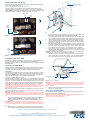
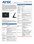
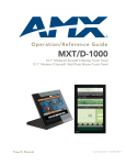
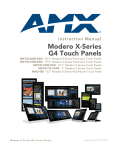
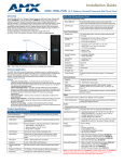
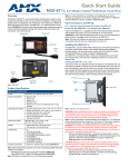
Quick Start Guide
MXD-1000 10.1" Modero X® Series Wall/Flush Mount Touch Panel
Overview
MXD-1000 (FG5968-07/13) Specifications (Cont.)
The MXD-1000 10.1” Modero X® Series Wall/Flush Mount Touch Panel, available in
portrait (FG5968-07) and landscape (FG5968-13) models, includes a beautiful,
panoramic capacitive multi-touch screen that provides users access to multiple
applications with minimal navigation. This new generation of touch panels is built for
usability, offering edge-to-edge capacitive touch glass with multi-touch capabilities. It
features advanced technology empowering users to operate AV equipment
seamlessly, while providing the ultimate in audio and video quality. With a lightning
fast processor, brilliant graphics and enhanced capabilities, the Modero X Series is the
control surface that simply delivers more.
For more information on installation and configuration, please refer to the
MXT/MXD-1000 Operation Reference Guide, available at www.amx.com.
Touch Panel Display (Cont.):
NFC Sensor
Sleep Button
Viewing Angle:
• Vertical: ± 89°
• Horizontal: ± 89°
Screen Resolution
(W x H):
• Landscape: 1280x800
• Portrait: 800x1280
Aspect Ratio (W x H):
• Landscape: 16:9
• Portrait: 9:16
Brightness:
400 cd/m2
Contrast Ratio:
700:1
Color Depth:
264K colors
Backlight Type:
LED
Touch Overlay:
Projected Capacitive; Multi-touch support, 3 simultaneous
max.
Communications:
FIG. 1 MXD-1000, Landscape and Portrait
Product Specifications
MXD-1000 (FG5968-07/13) Specifications
Power:
PoE (Power over Ethernet), 802.3af, class 3
Power Consumption:
• Full-On: 8W maximum
• Standby: 3.2 W
• Shutdown: 1 W
Front Panel Components:
Light Sensor:
Motion Sensor:
Photosensitive light detector for automatic adjustment of the
panel brightness.
Ethernet:
10/100 port, RJ-45 connector and cable. Supported IP and IPbased protocols: UCP, TCP, ICMP, ICSP, IGMP, DHCP, Telnet,
FTP, DNS, RFB (for VNC), HTTP
USB:
1 - USB host 2.0, Type A ports
Near Field
Communications
(NFC):
Supports standards ISO/IEC 15693, ISO/IEC 14443A, ISO/
IEC 14443B; Unique Identifier (UID), Typ Range=.25",
Max = .5"
Bluetooth:
HID Profile v1.1, Keyboard/Mouse Support, requires MXA-BT
Bluetooth Adaptor.
Video:
Supported Video
Codecs:
• MPEG2-TS: MPEG-2 Main Profile @High Level up to 720p
at 25 fps (decode only)
• MJPEG up to 720p at 25 fps (decode only)
Streaming/File Formats: MPEG-TS for MPEG-2; HTTP for MJPEG
Video Conferencing:
External application using on-board camera and microphone
through Micro-USB connection (Landscape only)
Audio:
Streaming/File Formats: WAV, MP3
Intercom:
Full Duplex VoIP, SIP v2.0 (supported with AMX-CSG)
Proximity detector to wake the panel when it is approached.
• Typical Range: 1 foot (30.48 cm)
• Maximum Range: 3 feet (91.44 cm)
• Range width: 10 degrees
Operating Environment:
•
•
•
•
LED Indicator:
Camera with active indicator (Landscape only)
Dimensions (HWD):
Sleep Button:
Single button on top of panel (Landscape) or left side
(Portrait) for placing panel in sleep mode, for powering off the
panel, and for accessing the Settings Pages.
• Landscape: 6 11/16" x 9 7/8" x 2 5/8" (171 mm x 252 mm x
67 mm)
• Portrait: 9 7/8" x 6 11/16" x 2 5/8" (252 mm x 171 mm x 67
mm)
Microphone:
-42dB ± 3dB sensitivity FET microphone
Speakers:
4 ohm, 2 Watt, 300Hz cutoff frequency
Camera:
HD 720P camera for video conferencing/video chat support
(Landscape only).
Weight:
2.0 lbs (0.91 Kg)
Certifications:
•
•
•
•
•
•
•
•
UL
FCC Part 15 Class B
C-Tick CISPR 22 Class B
CE EN 55022 Class B and EN 55024
CB Scheme IEC 60950-1
IC
IEC/EN-60950
RoHS
Included Accessories:
•
•
•
•
MXD-1000 Installation Guide (93-5968-07)
MXA-CLK Modero X Series Cleaning Kit (FG5968-16)
MXD-1000 Installation Template (68-5968-03)
MXD-1000 Back Box (68-5968-03)
Other AMX Equipment:
• PS-POE-AF-TC, POE Injector, 802.3af Compliant (
FG423-83)
• MXA-BT Bluetooth USB Adaptor (FG5968-19)
• CB-MXP10 Rough-In Box and Cover Plate for the 10" Wall
Mount Modero X Series Touch Panels (FG039-17)
• NXA-ENET8-2POE, Gigabit Switch, 8 Port POE, 2 Port
SFP (FG2178-63)
Rear Panel Components:
USB Port:
USB connector used for keyboard and mouse connections, or
for firmware uploads.
Micro-USB Port:
5-pin Micro-USB connector used for camera video and
microphone output only.
Ethernet 10/100 Port
and Cable:
10/100 Base-T RJ-45 connector for Ethernet connectivity and
PoE.
Touch Panel Display:
Display Type:
TFT Active Matrix Color LCD with In-Plane Switching (IPS)
technology.
Display Size:
• Landscape: 9.9" x 6.7" (252 mm x 170 mm), 12.0" (304 mm)
diagonal
• Portrait: 6.7" x 9.9" (170 mm x 252 mm), 12.0" (304 mm)
diagonal
Viewable Area:
• Landscape: 8.5" x 5.3" (217mm x 136mm), 10.1" (257mm)
diagonal
• Portrait: 5.3" x 8.5" (136 mm x 217 mm), 10.1" (257mm)
diagonal
Operating Temperature: 32° F to 104° F (0° C to 40° C)
Storage Temperature: 4° F to 140° F (-20° C to 60° C)
Humidity Operating: 20% to 85% RH
Humidity Storage: 5% to 85% RH
NOTE: The MXD-1000-P-NC (FG5968-25) and MXD-1000-L-NC (FG5968-26) No
Comm touch panels do not have camera, microphone, or NFC capability. These
otherwise have all of the functionality of the MXD-1000 panels.
Panel Connectors and Wiring
FIG. 2 shows the connectors located on the underside of the MXD-1000. The Micro-USB
Mounting Surface
port is used for camera video output.
Power for the MXD-1000 via Power Over Ethernet
Power for the MXD-1000 is supplied via Power Over Ethernet (PoE), utilizing an AMXcertified, capacitive touch-compliant PoE injector such as the PS-POE-AT High Power PoE
Injector (FG423-81) or other approved AMX PoE power source. The incoming Ethernet cable
should be connected to the RJ45 port on the MXD-1000 (FIG. 2 and FIG. 3).
Micro-USB
Port
Locking
Tabs
USB
Port
#4 Screws
Top
RJ45
Cable
Clip
Knockouts
RJ45
Port
Back Box
FIG. 4 MXD-1000 Back Box Installation (Portrait)
FIG. 2 Rear of the MXD-1000 (Landscape)
Top
RJ45
Cable
Clip
RJ45
Port
FIG. 3 Rear of the MXD-1000 (detail of the RJ45 connection)
knockout (Landscape) or a right-side knockout (Portrait), and the Micro-USB or USB
cables through a top knockout (Landscape) or left knockout (Portrait).
3.
Thread the incoming Ethernet and Micro-USB wiring (if Micro-USB access is desired)
from their terminal locations through the surface opening and through the knockouts.
4.
Push the back box flat into the mounting surface and secure with either the locking
tabs or #4 mounting screws (not included). In order to prevent damage to the touch
panel, make sure that any screws used are flush with the back box, and the back box
goes freely into the opening.
5.
Insert each connector into its corresponding location along the back of the MXD-1000.
Gently pull the RJ45 adapter from underneath the electronics cover (FIG. 3), attach the
RJ45 cable, and push the connection back under the cover. Lock the RJ45 cable into
the clip above the cable connection (FIG. 2) to facilitate the rest of the installation.
6.
Test the incoming wiring by attaching the panel connections to their terminal locations
and applying power. Verify that the panel is receiving power and functioning properly to
prevent repetition of the installation.
NOTE: Do not disconnect the connectors from the touch panel. The unit must be installed
with the attached connectors before being inserted into the drywall.
7.
Latch the panel onto the top hooks on the back box and rotate it down (Landscape)
onto the bottom snaps or on the left side and rotate it to the right (Portrait installation)
(FIG. 5). Press gently but firmly on the ends until the snaps “click” to lock it down.
Configuring the MXD-1000
The MXD-1000 is equipped with Settings Pages that allow you to set and configure various
features on the panel. For more information on connecting and configuring the
MXD-1000 to a network, please refer to the Modero X Series Programming Guide, available
at www.amx.com.
Latch Hooks
Installing the MXD-1000
The MXD-1000 can be installed either directly into a solid surface environment, using either
solid surface screws or the included locking tabs for different mounting options. For more
information, please refer to the MXD-1000 Operation/Reference Guide, available at
www.amx.com.
The MXD-1000 is contained within a clear outer housing known as the back box. This back
box is removed when installing the device into a wall or when using the optional Rough-In
Box accessory (FG039-17). For more information on back box removal, please refer to the
MXD/T-1000 Operation Reference Guide, available at www.amx.com.
Installing the MXD-1000 into a wall
The back box (FIG. 4) is designed to attach the panel to most standard wall and solid surface
materials. This back box has four locking tabs (two on top and two on bottom) to help lock the
back box to the wall. These locking tabs are only extended AFTER the back box is inserted
into the wall. Using the locking tabs is highly recommended for standard mounting surfaces
such as walls. For thin walls and solid surfaces, use #4 mounting screws (not included).
WARNING: When installing the back box, make sure that the assembly is in the correct
position and in the correct place. Once the locking tabs are extended and locked into place,
removing the back box may be difficult without having access to the back of the wall or
causing damage to the wall.
Note: In order to guarantee a stable installation of the MXD-1000, the thickness of the wall
material must be a minimum of .50 inches (1.27cm) and a maximum of .875 inches (2.22cm).
The surface should also be smooth and flat.
WARNING: The maximum recommended torque to screw in the locking tabs on the plastic
back box is 5 IN-LB [56 N-CM]. Applying excessive torque while tightening the tab screws,
such as with powered screwdrivers, can strip out the locking tabs or damage the plastic back
box.
1.
After ensuring proper placement, cut out the mounting surface, using the MXD-1000
Installation Template (68-5968-03) as a guide. Refer to the dimensions in the
MXD-1000 Operation/Reference Guide, available from www.amx.com, for more
information.
CAUTION: Making sure the actual cutout opening is slightly smaller than the provided
dimensions is highly recommended. This action provides the installer with a margin for error
if the opening needs to be expanded. Too little wall material removed is always better than
too much.
2.
Remove the back box knockouts (FIG. 4) and thread the incoming wiring through the
knockout holes.To facilitate installation, thread the Ethernet cable through a bottom
Back Box
Mounting Surface
Snaps
FIG. 5 Installing the MXD-1000
WARNING: if you see a gap between the panel and the back box, or feel any binding while
locking down the panel, stop immediately and verify that no cables or other items are in the
way. Do not force the panel into position, as this can cause damage to the touch screen or
the panel electronics.
8.
Reconnect the terminal Ethernet and USB to their respective locations on either the
Ethernet port or NetLinx Master.
Uninstalling the MXD-1000
For information on uninstalling the MXD-1000, please refer to the MXD/T-1000 Operation
Reference Guide, available at www.amx.com.
NOTE: For a demonstration of MXD-1000 uninstallation, please refer to the Modero X Wall
Removal video on the AMXconfigure channel on YouTube:
http://www.youtube.com/user/AMXconfigure/
For full warranty information, refer to the AMX Instruction Manual(s) associated with your Product(s).
10/13
©2013 AMX. All rights reserved. AMX and the AMX logo are registered trademarks of AMX.
AMX reserves the right to alter specifications without notice at any time.
3000 RESEARCH DRIVE, RICHARDSON, TX 75082 • 800.222.0193 • fax 469.624.7153 • technical support 800.932.6993 • www.amx.com
93-5968-07
REV: J