1
Operation/Reference Guide
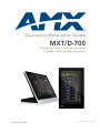
MXT/D-700
7" Modero® X Series Tabletop Touch Panel
7" Modero X® Series Wall/Flush Mount
Touch Panels
Last Updated: 9/23/2012
AMX Limited Warranty and Disclaimer
This Limited Warranty and Disclaimer extends only to products purchased directly from AMX or an AMX Authorized Partner which
include AMX Dealers, Distributors, VIP’s or other AMX authorized entity.
AMX warrants its products to be free of defects in material and workmanship under normal use for three (3) years from the date of
purchase, with the following exceptions:
•
Electroluminescent and LCD Control Panels are warranted for three (3) years, except for the display and touch overlay components are warranted for a period of one (1) year.
•
Disk drive mechanisms, pan/tilt heads, power supplies, and MX Series products are warranted for a period of one (1) year.
•
AMX lighting products are guaranteed to switch on and off any load that is properly connected to our lighting products, as long
as the AMX lighting products are under warranty. AMX also guarantees the control of dimmable loads that are properly connected to our lighting products. The dimming performance or quality there of is not guaranteed, impart due to the random combinations of dimmers, lamps and ballasts or transformers.
•
AMX software is warranted for a period of ninety (90) days.
•
Batteries and incandescent lamps are not covered under the warranty.
•
AMX AutoPatch Epica, Modula, Modula Series4, Modula CatPro Series and 8Y-3000 product models will be free of defects in
materials and manufacture at the time of sale and will remain in good working order for a period of three (3) years following the
date of the original sales invoice from AMX. The three-year warranty period will be extended to the life of the product (Limited
Lifetime Warranty) if the warranty card is filled out by the dealer and/or end user and returned to AMX so that AMX receives it
within thirty (30) days of the installation of equipment but no later than six (6) months from original AMX sales invoice date. The
life of the product extends until five (5) years after AMX ceases manufacturing the product model. The Limited Lifetime Warranty
applies to products in their original installation only. If a product is moved to a different installation, the Limited Lifetime Warranty
will no longer apply, and the product warranty will instead be the three (3) year Limited Warranty.
All products returned to AMX require a Return Material Authorization (RMA) number. The RMA number is obtained from the AMX
RMA Department. The RMA number must be clearly marked on the outside of each box. The RMA is valid for a 30-day period. After
the 30-day period the RMA will be cancelled. Any shipments received not consistent with the RMA, or after the RMA is cancelled, will
be refused. AMX is not responsible for products returned without a valid RMA number.
AMX is not liable for any damages caused by its products or for the failure of its products to perform. This includes any lost profits, lost
savings, incidental damages, or consequential damages. AMX is not liable for any claim made by a third party or by an AMX Authorized Partner for a third party.
This Limited Warranty does not apply to (a) any AMX product that has been modified, altered or repaired by an unauthorized agent or
improperly transported, stored, installed, used, or maintained; (b) damage caused by acts of nature, including flood, erosion, or earthquake; (c) damage caused by a sustained low or high voltage situation or by a low or high voltage disturbance, including brownouts,
sags, spikes, or power outages; or (d) damage caused by war, vandalism, theft, depletion, or obsolescence.
This limitation of liability applies whether damages are sought, or a claim is made, under this warranty or as a tort claim (including
negligence and strict product liability), a contract claim, or any other claim. This limitation of liability cannot be waived or amended by
any person. This limitation of liability will be effective even if AMX or an authorized representative of AMX has been advised of the
possibility of any such damages. This limitation of liability, however, will not apply to claims for personal injury.
Some states do not allow a limitation of how long an implied warranty last. Some states do not allow the limitation or exclusion of incidental or consequential damages for consumer products. In such states, the limitation or exclusion of the Limited Warranty may not
apply. This Limited Warranty gives the owner specific legal rights. The owner may also have other rights that vary from state to state.
The owner is advised to consult applicable state laws for full determination of rights.
EXCEPT AS EXPRESSLY SET FORTH IN THIS WARRANTY, AMX MAKES NO OTHER WARRANTIES, EXPRESSED OR
IMPLIED, INCLUDING ANY IMPLIED WARRANTIES OF MERCHANTABILITY OR FITNESS FOR A PARTICULAR PURPOSE. AMX
EXPRESSLY DISCLAIMS ALL WARRANTIES NOT STATED IN THIS LIMITED WARRANTY. ANY IMPLIED WARRANTIES THAT
MAY BE IMPOSED BY LAW ARE LIMITED TO THE TERMS OF THIS LIMITED WARRANTY. EXCEPT AS OTHERWISE LIMITED
BY APPLICABLE LAW, AMX RESERVES THE RIGHT TO MODIFY OR DISCONTINUE DESIGNS, SPECIFICATIONS, WARRANTIES, PRICES, AND POLICIES WITHOUT NOTICE.
AMX Software License and Warranty Agreement
•
LICENSE GRANT. AMX grants to Licensee the non-exclusive right to use the AMX Software in the manner described in this
License. The AMX Software is licensed, not sold. This license does not grant Licensee the right to create derivative works of the
AMX Software. The AMX Software consists of generally available programming and development software, product documentation, sample applications, tools and utilities, and miscellaneous technical information. Please refer to the README.TXT file on
the compact disc or download for further information regarding the components of the AMX Software. The AMX Software is subject to restrictions on distribution described in this License Agreement. AMX Dealer, Distributor, VIP or other AMX authorized
entity shall not, and shall not permit any other person to, disclose, display, loan, publish, transfer (whether by sale, assignment,
exchange, gift, operation of law or otherwise), license, sublicense, copy, or otherwise disseminate the AMX Software. Licensee
may not reverse engineer, decompile, or disassemble the AMX Software.
•
ACKNOWLEDGEMENT. You hereby acknowledge that you are an authorized AMX dealer, distributor, VIP or other AMX authorized entity in good standing and have the right to enter into and be bound by the terms of this Agreement.
•
INTELLECTUAL PROPERTY. The AMX Software is owned by AMX and is protected by United States copyright laws, patent
laws, international treaty provisions, and/or state of Texas trade secret laws. Licensee may make copies of the AMX Software
solely for backup or archival purposes. Licensee may not copy the written materials accompanying the AMX Software.
•
TERMINATION. AMX RESERVES THE RIGHT, IN ITS SOLE DISCRETION, TO TERMINATE THIS LICENSE FOR ANY REASON UPON WRITTEN NOTICE TO LICENSEE. In the event that AMX terminates this License, the Licensee shall return or
destroy all originals and copies of the AMX Software to AMX and certify in writing that all originals and copies have been
returned or destroyed.
•
PRE-RELEASE CODE. Portions of the AMX Software may, from time to time, as identified in the AMX Software, include PRERELEASE CODE and such code may not be at the level of performance, compatibility and functionality of the GA code. The
PRE-RELEASE CODE may not operate correctly and may be substantially modified prior to final release or certain features may
not be generally released. AMX is not obligated to make or support any PRE-RELEASE CODE. ALL PRE-RELEASE CODE IS
PROVIDED "AS IS" WITH NO WARRANTIES.
•
LIMITED WARRANTY. AMX warrants that the AMX Software (other than pre-release code) will perform substantially in accordance with the accompanying written materials for a period of ninety (90) days from the date of receipt. AMX DISCLAIMS ALL
OTHER WARRANTIES, EITHER EXPRESS OR IMPLIED, INCLUDING, BUT NOT LIMITED TO IMPLIED WARRANTIES OF
MERCHANTABILITY AND FITNESS FOR A PARTICULAR PURPOSE, WITH REGARD TO THE AMX SOFTWARE. THIS LIMITED WARRANTY GIVES LICENSEE SPECIFIC LEGAL RIGHTS. Any supplements or updates to the AMX SOFTWARE,
including without limitation, any (if any) service packs or hot fixes provided to Licensee after the expiration of the ninety (90) day
Limited Warranty period are not covered by any warranty or condition, express, implied or statutory.
•
LICENSEE REMEDIES. AMX's entire liability and Licensee's exclusive remedy shall be repair or replacement of the AMX Software that does not meet AMX's Limited Warranty and which is returned to AMX in accordance with AMX's current return policy.
This Limited Warranty is void if failure of the AMX Software has resulted from accident, abuse, or misapplication. Any replacement AMX Software will be warranted for the remainder of the original warranty period or thirty (30) days, whichever is longer.
Outside the United States, these remedies may not available. NO LIABILITY FOR CONSEQUENTIAL DAMAGES. IN NO
EVENT SHALL AMX BE LIABLE FOR ANY DAMAGES WHATSOEVER (INCLUDING, WITHOUT LIMITATION, DAMAGES
FOR LOSS OF BUSINESS PROFITS, BUSINESS INTERRUPTION, LOSS OF BUSINESS INFORMATION, OR ANY OTHER
PECUNIARY LOSS) ARISING OUT OF THE USE OF OR INABILITY TO USE THIS AMX SOFTWARE, EVEN IF AMX HAS
BEEN ADVISED OF THE POSSIBILITY OF SUCH DAMAGES. BECAUSE SOME STATES/COUNTRIES DO NOT ALLOW
THE EXCLUSION OR LIMITATION OF LIABILITY FOR CONSEQUENTIAL OR INCIDENTAL DAMAGES, THE ABOVE LIMITATION MAY NOT APPLY TO LICENSEE.
•
U.S. GOVERNMENT RESTRICTED RIGHTS. The AMX Software is provided with RESTRICTED RIGHTS. Use, duplication, or
disclosure by the Government is subject to restrictions as set forth in subparagraph ©(1)(ii) of The Rights in Technical Data and
Computer Software clause at DFARS 252.227-7013 or subparagraphs ©(1) and (2) of the Commercial Computer Software
Restricted Rights at 48 CFR 52.227-19, as applicable.
•
SOFTWARE AND OTHER MATERIALS FROM AMX.COM MAY BE SUBJECT TO EXPORT CONTROL. The United States
Export Control laws prohibit the export of certain technical data and software to certain territories. No software from this Site may
be downloaded or exported (i) into (or to a national or resident of) Cuba, Iraq, Libya, North Korea, Iran, Syria, or any other country to which the United States has embargoed goods; or (ii) anyone on the United States Treasury Department's list of Specially
Designated Nationals or the U.S. Commerce Department's Table of Deny Orders. AMX does not authorize the downloading or
exporting of any software or technical data from this site to any jurisdiction prohibited by the United States Export Laws.
This Agreement replaces and supersedes all previous AMX Software License Agreements and is governed by the laws of
the State of Texas, and all disputes will be resolved in the courts in Collin County, Texas, USA. For any questions concerning this Agreement, or to contact AMX for any reason, please write: AMX License and Warranty Department, 3000 Research
Drive, Richardson, TX 75082.
Table of Contents
Table of Contents
Modero X® Series Touch Panels ........................................................................1
Overview .................................................................................................................. 1
Features.................................................................................................................... 1
Modero X Dealer Benefits ........................................................................................ 1
Modero X Customer Benefits ................................................................................... 1
MXT-700 ................................................................................................................... 2
Connector Locations ....................................................................................................... 4
Memory........................................................................................................................... 4
Basic Operation............................................................................................................... 5
Powering on the MXT-700 .............................................................................................. 5
Microphone ..................................................................................................................... 5
Audio/Video Capabilities ................................................................................................ 5
MXT-700-NC ............................................................................................................. 5
MXD-700 .................................................................................................................. 5
Memory........................................................................................................................... 8
Basic Operation............................................................................................................... 8
Powering on the MXD-700.............................................................................................. 8
Microphone ..................................................................................................................... 8
Audio/Video Capabilities ................................................................................................ 8
MXD-700-NC ............................................................................................................ 8
MXD/T-700 Features ................................................................................................ 9
Picture View .................................................................................................................... 9
Preview Mode and Normal Mode ................................................................................. 10
Picture View Send Command ........................................................................................ 11
Configuration.......................................................................................................... 11
Bluetooth Support .................................................................................................. 11
NFC......................................................................................................................... 11
Cleaning the Touch Overlay and Case........................................................................... 12
Installation ........................................................................................................13
MXT-700 Installation............................................................................................... 13
Power via Power Over Ethernet ............................................................................. 13
Ethernet Cable Installation and Modification.......................................................... 13
MXD-700 Installation .............................................................................................. 14
Power Via Power Over Ethernet ................................................................................... 15
Installing the MXD-700 into a wall ................................................................................ 16
Uninstalling the MXD-700....................................................................................... 20
MXD/T-700 7" Modero® X Series Touch Panels
1
Table of Contents
Configuration and Programming ......................................................................21
Modero X Series Programming Guide .................................................................... 21
Upgrading Firmware .........................................................................................23
Overview ................................................................................................................ 23
Upgrading Firmware via USB Flash Drive ............................................................... 23
Load the Firmware on a USB Flash Drive ...................................................................... 23
Transfer the Firmware File From the Flash Drive to the Touch Panel............................ 24
Upgrading from Previous Firmware ........................................................................ 25
Returning to Factory Default Firmware .................................................................. 25
Upgrading Firmware Via NetLinx Studio ................................................................ 26
Viewing devices on the Virtual System.......................................................................... 28
Downloading firmware .................................................................................................. 28
Appendix: Troubleshooting ..............................................................................31
Overview ................................................................................................................ 31
Panel Doesn’t Respond To Touches .............................................................................. 31
Panel Isn’t Appearing In The Online Tree Tab ............................................................... 31
Can’t Connect To a NetLinx Master .............................................................................. 31
Only One Modero Panel In My System Shows Up ......................................................... 31
2
MXD/T-700 7" Modero® X Series Touch Panels
Modero X® Series Touch Panels
Modero X® Series Touch Panels
Overview
See more and do more with the most elegant interface designed specifically for dedicated room control. The
Modero X® Series Touch Panels provide several industry firsts, including a beautiful, panoramic capacitive
multi-touch screen that provides users access to multiple applications with minimal navigation. It is hardwareready for support of Near Field Communication™ (NFC) Technology, to allow personalization of the user
experience and productivity enhancing capabilities through integration with NFC capable personal devices.
The distinctive, low-profile design is engineered to sit perfectly on a table without obstructing views. Modero
X Series is the control surface that simply delivers more.
Features
Panoramic Control Surface – Combined with the new PanTastic UI, the panoramic touch panels
take the user experience to a whole new level with an impressive control surface to perform
activities much in the same way you use a computer – multi-tasking with dedicated spaces.
Future Technology Visions – HD video chat and conferencing using integrated camera and
hardware - ready to support Near Field Communication (NFC) Technology, which promises
short-range wireless technologies that deliver peer-to-peer communication by 'sharing, pairing and
transaction' between RF devices like exchanging data/identities.
Enhanced Usability – External phone connections via Bluetooth or USB and HD video streaming.
Graphic Leaps & Bounds – The Modero X Series includes some striking new intuitive UI
functionality including: gesturing, swiping, dynamic reordering and enhanced animation
capabilities
Perfect From Any Angle – Includes In-Plane Switching (IPS), the latest technology in popular
tablet/mobile devices that delivers the widest viewing angles and the most accurate color
reproduction on the market.
Modero X Dealer Benefits
Attract More Corporate Customers - The elegant design and simple beauty of the Modero X
Series will create demand from both new and current customers.
Address Unique Requirements – With a panoramic profile, the Modero X Series provides dealers
with a solution for uses where multiple applications must be viewed simultaneously.
Differentiate Yourself – The Modero X Series offers design and technology features unmatched in
the industry.
Modero X Customer Benefits
Multi-Task Capability – The contemporary design provides a large control surface, which allows
multiple views for different activities such as presenting, controlling and previewing.
Simple to Use Interfaces – The capacitive multi-touch screen combined with intuitive user-
interfaces makes it easy for anyone to operate sophisticated meeting room equipment
Sleek, Low-Profile Design - The Modero X Series is engineered to sit perfectly on a table without
obstructing views.
MXD/T-700 7" Modero® X Series Touch Panels
1
Modero X® Series Touch Panels
MXT-700
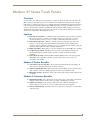
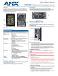
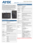
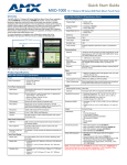
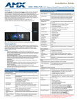
The MXT-700 7" Modero X® Series Tabletop Touch Panel (FG5968-04) (FIG. 1) is ideal for boardrooms,
conference rooms, or auditoriums where a panoramic control surface is needed to provide access to multiple
functions simultaneously while remaining elegantly unobtrusive. In residences, it is perfect for kitchens, home
theaters, or home offices where the panoramic control surface can be used to manage systems throughout the
house.
NFC Sensor
Sleep Button
5.0"
(126 mm)
7 5/16"
(187 m)
FIG. 1 MXT-700 touch panel
The MXT-700 features a 7.3" x 4.8" (186 mm x 122 mm), 8.8" (222 mm) diagonal display, with a viewable
area of 6.05" x 3.54" (154 mm x 90 mm), 7.0" (178 mm) diagonal.
The device communicates via Ethernet (10/100 port, RJ-45 connector, supported IP and IP-based protocols:
UCP, TCP, ICMP, ICSP, IGMP, DHCP, Telnet, FTP, DNS, RFB for VNC, and HTTP) and USB (2 USB host
2.0, Type A ports).
The MXT-700 also supports Near Field Communication (NFC) technology (please see the NFC section on
page 11 for more information) and Bluetooth keyboard and mouse use via the optional MXA-BT Bluetooth
Adapter.
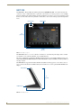
Sleep Button
5"
(74 mm)
USB Ports (2)
4 1/8" (105 mm)
FIG. 2 MXT-700 side view
2
MXD/T-700 7" Modero® X Series Touch Panels
Modero X® Series Touch Panels
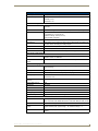
MXT-700 Specifications
Power Requirements:
Power Consumption:
PoE (Power over Ethernet), 802.3af, class 3
• Full-On: 8W maximum
• Standby: 3.2 W
• Shutdown: 1 W
Front Panel Components:
NFC Transceiver:
Antenna and transceiver for Near Field Communications device detection and
interaction.
Light Sensor:
Photosensitive light detector for automatic adjustment of the panel brightness.
Motion Sensor:
Proximity detector to wake the panel when it is approached.
• Typical Range: 1 foot (30.48 cm)
• Maximum Range: 3 feet (91.44 cm)
• Range width: 10 degrees
LED Indicator:
Camera active indicator
Sleep Button:
Single button on top of panel for placing panel in sleep mode, for powering off
the panel, and for accessing the Settings Pages.
Microphone:
-42dB ± 3dB sensitivity FET microphone
Speakers:
4 ohm, 2 Watt, 300Hz cutoff frequency
Camera:
HD 720P camera for video conferencing/video chat support.
Rear Panel Components:
USB connections:
2 easily accessible USB ports on rear of base, used for connection to
keyboard, mouse, or USB drive.
Ethernet 10/100 Port and
Cable:
10/100 Base-T RJ-45 connector for Ethernet connectivity and PoE.
Touch Panel Display:
Display Type:
TFT Active Matrix Color LCD with Fringe Field Switching (FFS) - Wide viewing
angle technology
Display Size:
7.3" x 4.8" (186 mm x 122 mm), 8.8" (222 mm) diagonal
Viewable Area:
6.05" x 3.54" (154 mm x 90 mm), 7.0" (178 mm) diagonal
Viewing Angle:
• Vertical: ± 89°
• Horizontal: ± 89°
Screen Resolution
(W x H):
1024x600
Aspect Ratio (W x H):
16x9
Brightness:
400 cd/m2
Contrast Ratio:
800:1
Color Depth:
16,7M colors
Backlight Type:
LED
Touch Overlay:
Projected Capacitive; Multi-touch support, 3 simultaneous max.
Communications:
Ethernet:
10/100 port, RJ-45 connector and cable. Supported IP and IP-based protocols:
UCP, TCP, ICMP, ICSP, IGMP, DHCP, Telnet, FTP, DNS, RFB (for VNC), HTTP
USB:
2 - USB host 2.0, Type A ports
Near Field Communications Supports standards ISO/IEC 15693, ISO/IEC 14443A, ISO/IEC 14443B;
(NFC):
Unique Identifier (UID), Typical Range = .25”, Maximum Range = .5"
Bluetooth:
MXD/T-700 7" Modero® X Series Touch Panels
HID Profile v1.1, Keyboard/Mouse Support, requires MXA-BT Bluetooth
Adaptor.
3
Modero X® Series Touch Panels
MXT-700 Specifications (Cont.)
Video:
Supported Video Codecs:
• MPEG2-TS: MPEG-2 Main Profile @High Level up to 720p at 25 fps (decode
only)
• MJPEG up to 720p at 25 fps (decode only)
Streaming/File Formats:
MPEG-TS for MPEG2; HTTP for MJPEG
Audio:
Streaming/File Formats:
WAV, MP3
Intercom:
Full Duplex VoIP, SIP v2.0 (supported with AMX-CSG)
Operating Environment:
• Operating Temperature: 32° F to 104° F (0° C to 40° C)
• Storage Temperature: 4° F to 140° F (-20° C to 60° C)
• Humidity Operating: 20% to 85% RH
• Humidity Storage: 5% to 85% RH
• Power ("Heat") Dissipation: On: 27.3 BTU/hr, Standby: 10.9 BTU/hr
Dimensions (HWD):
5" x 7 5/16" x 4 1/8" (126 mm x 187 mm x 105 mm)
Weight:
1.8 lbs (0.82 Kg)
Certifications:
• FCC Part 15 Class B
• C-Tick CISPR 22 Class B
• CE EN 55022 Class B and EN 55024
• CB Scheme IEC 60950-1
• IC
• IEC/EN-60950
• RoHS
Included Accessories:
• MXT-700 Installation Guide (93-5968-03)
• MXA-CLK Modero X Series Cleaning Kit (FG5968-16)
• HPG-10 .75-inch Hydraport .75-IN. Grommet (FG570-01)
• MXA-USB-C USB Cover Kit (FG5968-18)
Other AMX Equipment:
• PS-POE-AT, High-Power PoE Injector (FG423-81)
• PS-POE-AF-TC, POE Injector, 802.3af Compliant (FG423-83)
• MXA-BT Bluetooth USB Adaptor (FG5968-19)
• MXA-CLK, Modero X Series Cleaning Kit (FG5968-16)
• NXA-ENET8POE, Gigabit PoE Ethernet Switch (FG2178-62)
• NXA-ENET8-2POE, Gigabit Switch, 8 Port POE, 2 Port SFP (FG2178-63)
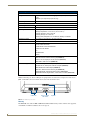
Connector Locations
With the unit facing you, the two USB ports for peripherals are located on the rear right corner of the device
(FIG. 3). The RJ45 connector for PoE is also located on the back of the device.
USB Ports
Entry for RJ45/
PoE Cable
Speaker
FIG. 3 MXT-700 USB port location
Memory
The MXT-700 comes with 512 MB of SDRAM and 4 GB of Flash memory, neither of which can be upgraded.
A maximum of 2.4 GB is available to the user for projects.
4
MXD/T-700 7" Modero® X Series Touch Panels
Modero X® Series Touch Panels
Basic Operation
The MXT-700 is operated using its integral touchscreen, as well as the Sleep button on the top of the device
(FIG. 1). If the device has gone into its Sleep Mode, a touch of the touchscreen or of the Sleep button will
reactivate it.
Powering on the MXT-700
The MXT-700 may be powered on by touching and holding the Sleep button on the top of the device.
Microphone
The MXT-700 contains a built-in microphone above the touch screen for video and audio conferencing
capabilities. This microphone is concealed by the casing.
Audio/Video Capabilities
The MXT-700 has the capability of displaying multiple JPEG and PNG files at one time. The device also
supports streaming motion JPEG video (of the sort used by many IP and Web cameras), as well as MP3 and
WAV audio files.
MXT-700-NC
The MXT-700-NC (FG5968-27) No Comm touch panel does not have camera or microphone capability. It
otherwise has all of the functionality of the MXT-700 panel.
MXD-700
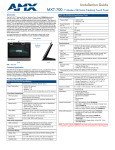
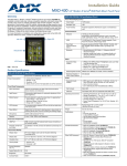
The MXD-700 7” Modero X Series Wall/Flush Mount Touch Panels (Portrait Wall Mount: FG5968-08;
Landscape Wall Mount: FG5968-14) are ideal for boardrooms, conference rooms, or auditoriums where a
panoramic control surface is needed to provide access to multiple functions simultaneously while remaining
elegantly unobtrusive. In residences, they are perfect for kitchens, home theaters, or home offices where the
panoramic control surface can be used to manage systems throughout the house.
The MXD-700 features a 7.3" x 4.8" (186 mm x 122 mm), 8.8" (222 mm) diagonal (Landscape) or 4.8" x 7.3"
(122 mm x 186 mm), 8.8" (222 mm) diagonal (Portrait) display, with a viewable area of 6.05" x 3.54" (154
mm x 90 mm), 7.0" (178 mm) diagonal (Landscape) or 3.54" x 6.05" (90 mm x 154 mm), 7.0" (178 mm)
diagonal.
The device communicates via Ethernet (10/100 port, RJ-45 connector, supported IP and IP-based protocols:
UCP, TCP, ICMP, ICSP, IGMP, DHCP, Telnet, FTP, DNS, RFB for VNC, and HTTP) and USB (1 USB host
2.0, Type A port).
The MXD-700 also supports Near Field Communication (NFC) technology (please see the NFC section on
page 11 for more information) and Bluetooth keyboard and mouse use via the optional MXA-BT Bluetooth
Adapter.
NFC Sensor
Sleep Button
FIG. 4 MXD-700, Landscape Wall Mount
MXD/T-700 7" Modero® X Series Touch Panels
5
Modero X® Series Touch Panels
Sleep Button
NFC Sensor
FIG. 5 MXD-700 (Portrait Wall Mount)
MXD-700 Specifications
Power Requirements:
PoE (Power over Ethernet), 802.3af, class 3
Power Consumption:
• Full-On: 8W maximum
• Standby: 3.2 W
• Shutdown: 1 W
Front Panel Components:
NFC Transceiver:
Antenna and transceiver for Near Field Communications device detection and
interaction.
Light Sensor:
Photosensitive light detector for automatic adjustment of the panel brightness.
Motion Sensor:
Proximity detector to wake the panel when it is approached.
• Typical Range: 1 foot (30.48 cm)
• Maximum Range: 3 feet (91.44 cm)
• Range width: 10 degrees
LED Indicator:
Camera active indicator (landscape only)
Sleep Button:
Single button on edge of panel for placing panel in sleep mode, for powering off
the panel, and for accessing the Settings Pages.
Microphone:
-42dB ± 3dB sensitivity FET microphone
Speakers:
4 ohm, 2 Watt, 300Hz cutoff frequency
Camera (landscape only:
HD 720P camera for video conferencing/video chat support.
Rear Panel Components:
USB Port:
USB connector used for keyboard and mouse connections, or for firmware
uploads.
Ethernet 10/100 Port:
10/100 Base-T RJ-45 connector for Ethernet connectivity and PoE.
Touch Panel Display:
Display Type:
Display Size:
TFT Active Matrix Color LCD with Fringe Field Switching (FFS) - Wide viewing
angle technology
• Landscape: 7.3" x 4.8" (186 mm x 122 mm), 8.8" (222 mm) diagonal
• Portrait: 4.8" x 7.3" (122 mm x 186 mm), 8.8" (222 mm) diagonal
6
MXD/T-700 7" Modero® X Series Touch Panels
Modero X® Series Touch Panels
MXD-700 Specifications (Cont.)
Touch Panel Display (Cont.):
Viewable Area
(W x H):
• Landscape: 6.05" x 3.54" (154 mm x 90 mm), 7.0" (178 mm) diagonal
Viewing Angle:
• Vertical: ± 89°
• Portrait: 3.54" x 6.05" (90 mm x 154 mm), 7.0" (178 mm) diagonal
• Horizontal: ± 89°
Screen Resolution
(W x H):
• Landscape: 1024x600
Aspect Ratio
(W x H):
• Landscape: 16:9
Brightness:
400 cd/m2
Contrast Ratio:
700:1
• Portrait: 600x1024
• Portrait: 9:16
Color Depth:
16,7M colors
Backlight Type:
LED
Touch Overlay:
Projected Capacitive; Multi-touch support, 3 simultaneous max.
Communications:
Ethernet:
10/100 port, RJ-45 connector and cable. Supported IP and IP-based protocols:
UCP, TCP, ICMP, ICSP, IGMP, DHCP, Telnet, FTP, DNS, RFB (for VNC), HTTP
USB:
1 - USB host 2.0, Type A ports
Near Field Communications Supports standards ISO/IEC 15693, ISO/IEC 14443A, ISO/IEC 14443B;
(NFC):
Unique Identifier (UID), Typical Range = .25", Maximum Range = .5"
Bluetooth:
HID Profile v1.1, Keyboard/Mouse Support, requires MXA-BT Bluetooth
Adaptor.
Video:
Streaming/File Formats:
MPEG-TS for MPEG2; HTTP for MJPEG
Audio:
Streaming/File Formats:
WAV, MP3
Intercom:
Full Duplex VoIP, SIP v2.0 (supported with AMX-CSG)
Operating
Environment:
• Operating Temperature: 32° F to 104° F (0° C to 40° C)
• Storage Temperature: 4° F to 140° F (-20° C to 60° C)
• Humidity Operating: 20% to 85% RH
• Humidity Storage: 5% to 85% RH
• Power ("Heat") Dissipation: On: 27.3 BTU/hr, Standby: 10.9 BTU/hr
Dimensions (HWD):
• Landscape: 4.8" x 7.3" x 2.5" (122 mm x 186 mm x 63 mm)
• Portrait: 7.3" x 4.8" x 2.5" (186 mm x 122 mm x 63 mm)
Weight:
Certifications:
1.4 lbs (0.64 Kg)
• FCC Part 15 Class B
• C-Tick CISPR 22 Class B
• CE EN 55022 Class B and EN 55024
• CB Scheme IEC 60950-1
• IC
• IEC/EN-60950
• RoHS
Included Accessories:
• MXD-700 Installation Guide (93-5968-07)
• MXA-CLK Modero X Series Cleaning Kit (FG5968-16)
• MXD-700 Installation Template (68-5968-04)
MXD/T-700 7" Modero® X Series Touch Panels
7
Modero X® Series Touch Panels
MXD-700 Specifications (Cont.)
Other AMX Equipment:
• PS-POE-AT, High Power PoE Injector (FG423-81)
• PS-POE-AF-TC, POE Injector, 802.3af Compliant (FG423-83)
• MXA-BT Bluetooth USB Adaptor (FG5968-19)
• CB-MXP7, Rough-In Box and Cover Plate for Modero X Series Touch Panel,
7" (FG039-18)
• NXA-ENET8POE, Gigabit PoE Ethernet Switch (FG2178-62)
• NXA-ENET8-2POE, Gigabit Switch, 8 Port POE, 2 Port SFP (FG2178-63)
USB
Port
Top
RJ45
Cable
Clip
RJ45
Port
FIG. 6 Rear of the MXD-700 (Landscape)
Memory
The MXD-700 comes with 512 MB of SDRAM and 4 GB of Flash memory, neither of which can be upgraded.
A maximum of 2.4 GB is available to the user for projects.
Basic Operation
The MXD-700 is operated using its integral touchscreen, as well as the Sleep button on the top of the device
(FIG. 4). If the device has gone into its Sleep Mode, a touch of the touchscreen or of the Sleep button will
reactivate it.
Powering on the MXD-700
The MXD-700 may be powered on by touching and holding the Sleep button on the top of the device.
Microphone
The MXD-700 contains a built-in microphone above the touch screen for video and audio conferencing
capabilities. This microphone is concealed by the casing.
Audio/Video Capabilities
The MXD-700 has the capability of displaying multiple JPEG and PNG files at one time. The device also
supports streaming motion JPEG video (of the sort used by many IP and Web cameras), as well as MP3 and
WAV audio files.
MXD-700-NC
The MXD-700-P-NC (FG5968-28) and MXD-700-L-NC (FG5968-29) No Comm touch panels do not have
camera or microphone capability. These otherwise have all of the functionality of the MXD-700 panels.
8
MXD/T-700 7" Modero® X Series Touch Panels
Modero X® Series Touch Panels
MXD/T-700 Features
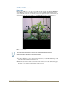
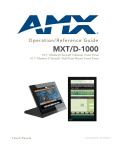
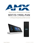
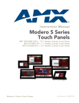
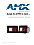
Picture View
By connecting a USB drive via one of the device’s USB ports (FIG. 3), Picture View allows the MXT-700 to
access JPEG images on that drive and display them on the touchscreen (FIG. 7). Individual images may be
accessed at any time, or the entire collection may be displayed for predetermined times. Picture View may be
stopped at any time by removing the USB drive, and the MXT-700 will return to its default display page.
FIG. 7 Picture View display
The maximum source resolution for Picture View is 1920x1920 pixels.The maximum
displayed resolution is the same as the screen resolution.
To start Picture View:
1. Connect a USB drive to the device. Picture View will automatically recognize all available images on the
drive and start displaying them on the touchscreen.
2. When the images begin to display, touch any place on the touchscreen to open the configuration popup
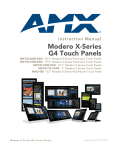
menu (FIG. 8). If no selection is made, this menu will remain in place for 15 seconds and then disappear.
It may be accessed again by touching anywhere on the touchscreen.
MXD/T-700 7" Modero® X Series Touch Panels
9
Modero X® Series Touch Panels
Pause/
Resume
Stop
Random/
A-Z
Counter
Previous image
saved
Next image
saved
Timer
FIG. 8 Picture View configuration popup menu
3. On the leftmost amber button, select between Rand (images display at random) and A-Z (images display
in alphabetical order based on the name of the file).
4. The four grey buttons allow scrolling through saved images and the rate of display:
The Previous Image Saved button returns the display to the first image uploaded by Page View.
The Stop button stops Page View and returns to the default panel page.
The Pause/Resume button allows the display to stop on one particular image. Press it again to
resume the display procession.
The Next Image Saved button returns the display to the last image uploaded by Page View. If the
panel has not accessed all of the images available on a USB drive, Page View will display the last
one uploaded to date.
5. On the rightmost red button, select the number of seconds a selected image will be displayed in Picture
View. This may be selected between 5, 10, 15, 30, and 60 seconds.
6. The counter beneath the buttons displays the number of images currently uploaded by the MXT-700
versus the number detected on the USB drive.
Preview Mode and Normal Mode
Picture View has two modes: Preview Mode and Normal Mode. Preview Mode allows the user to configure
Picture View. Once a USB drive containing images is inserted into the panel, the images will begin to display.
Touching any place on the display will result in the configuration popup to slide from the bottom of the
display.
Picture View goes into its Normal Mode when the MXT-700 goes into idle timeout while connected to a USB
drive. Normal Mode displays images until the touchscreen is touched, or some other wakeup event is detected.
When the device goes back into timeout, Normal Mode will return to displaying images until the USB drive is
removed from the device.
10
MXD/T-700 7" Modero® X Series Touch Panels
Modero X® Series Touch Panels
Picture View Send Command
The ^PIC Send Command stops either mode of Picture View, or starts Preview Mode. For more information,
please refer to the Modero X Series Programming Guide, available at www.amx.com.
All images must be in JPEG format. PNG and other image formats cannot be viewed
through Picture View.
Configuration
The MXT-700 and MXD-700 are equipped with Settings Pages that allow you to set and configure various
features on the panels. For more information on connecting and configuring the touch panels to a network,
please refer to the Modero X Series Programming Guide, available at www.amx.com.
Bluetooth Support
Both the MXT-700 and the MXD-700 allow the use of Bluetooth keyboard and mouse combinations, using
HID Profile v1.1. Using a keyboard and mouse with the device requires use of the MXA-BT Bluetooth USB
Adapter (FG5968-19).
NFC
Both the MXT-700 and the MXD-700 support Near Field Communications™ (NFC) Technology. NFC
technology facilitates making transactions, exchanging digital content, and connecting electronic devices with
a touch. NFC transmissions are short-range (from a touch to a few centimeters), working with existing
contactless card technologies and containing built-in capabilities to support secure applications. By using NFC
technology, users may receive access to touch panels and touch panel pages through access badges and other
card options.
Common Access Card (CAC) Support In MXT/D-1000
Card Type
15693
Card Unique
Identifier (UID)
Card Data
Personal Identity
Verification (PIV)
Card holder UID
8 byte UID
Not Supported
N/A
14443A Non-Gov't
4, 7 or 10 byte UID (1)
Not Supported
N/A
14443A Gov't
4, 7 or 10 byte UID (1)
Not Supported (2)
Not currently
14443B Non-Gov't
4 byte UID
Not Supported
N/A
14443B Gov't
4 byte UID
Not Supported (2)
Not currently
FeliCa
Not Supported
Not Supported
N/A
(1) The UID can be a fixed unique number or a random number dynamically generated by the card.
(2) Requires contact card reader (not accessible via NFC)
The maximum range for the NFC antenna is 0.5" (12.7 mm), but the typical usage range is 0.25" (6.35 mm).
The antenna itself is accessible from the front of the panel, 3.25" (82.55 mm) from the left corner of the panel
and 0.375" (9.53 mm) from the top edge. When using an NFC device with the MXT-700, you should align
your device’s antenna with the center of the touch panel’s antenna (FIG. 1 and FIG. 4).
To facilitate NFC antenna access, you may want to add an icon to the panel’s
page(s), pointing to the location of the antenna on the panel.
For further information, please refer to the video available at the AMX Configure
channel on YouTube: http://www.youtube.com/user/AMXconfigure
MXD/T-700 7" Modero® X Series Touch Panels
11
Modero X® Series Touch Panels
Cleaning the Touch Overlay and Case
Both the MXT-700 and the MXD-700 come with the MXA-CLK Modero X Series Cleaning Kit (FG5968-16),
which may be used to clean fingerprints and dirt from the device. This kit comes with cleaning cloths and a
bottle of cleaning fluid specifically for use with the device.
When cleaning the device, do not directly spray the device with cleaning fluid. Instead, spray the cloth and
then apply the cloth to the touch screen. Do NOT use abrasives of any type to clean the device, as abrasives
may permanently damage or remove the device’s finish.
12
MXD/T-700 7" Modero® X Series Touch Panels
Installation
Installation
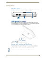
MXT-700 Installation
Any USB peripherals (mouse, keyboard, etc.) may be connected to one of the two USB ports on the rear of the
device (FIG. 9). Updates to the device’s firmware are also made via the USB ports.
Entry for RJ45/
PoE Cable
USB Ports
Speaker
FIG. 9 Connectors on the rear of the MXT-700
Power via Power Over Ethernet
Power for the MXT-700 is supplied via Power Over Ethernet (PoE), utilizing an AMX-certified, capacitive
touch-compliant PoE injector or other approved AMX PoE power source. The incoming Ethernet cable should
be connected to the RJ45 port on the cable attached to the device (FIG. 10).
RJ45 Port
Cable length
edited for clarity
FIG. 10 Back of the MXT-700, showing RJ45 port and cable for PoE
Ethernet Cable Installation and Modification
In installations where you wish to conceal the Ethernet cable, a hole at least 1.00” (2.54 cm) in diameter is
required in the surface to allow passage of the female RJ45 connector (FIG. 10). If using a smaller hole is
unavoidable, you will need to disconnect the Ethernet cable (ECA5968-05) from the device.
The minimum diameter hole through which the Ethernet cable may pass is 0.50"
(1.27 cm).
MXD/T-700 7" Modero® X Series Touch Panels
13
Installation
MXT-700
Ethernet Cable
Clamp
Connector
FIG. 11 Bottom of the MXT-700
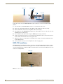
To disconnect and reconnect the MXT-700’s Ethernet cable to allow use of a hole smaller than 1.00” in
diameter:
1. On a soft surface, turn the MXT-700 face-down to access the bottom of the device.
2. Remove the clamp holding the Ethernet cable (FIG. 11) until the Ethernet cable moves freely.
3. Remove the Ethernet cable connector and pull the cable out of the clamp.
4. Pass the Ethernet cable (ECA5968-05) through the hole, with the RJ45 connector on the other side of the
installation surface from the device.
5. Press the Ethernet cable back into the clamp. Do NOT tighten the clamp at this time.
6. Using a nonconductive item such as a wooden stick, reinsert the Ethernet cable connector into the device.
Use the stick to ensure that the connector is properly seated.
7. Tighten the clamp to secure the Ethernet cable. Make sure the clamp is around the bundled black cable,
not the individual wires
8. Connect the RJ45 connector to its incoming Ethernet cable and apply power.
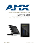
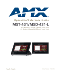
MXD-700 Installation
The MXD-700 may be installed directly into a solid surface environment, using either solid surface screws or
the included locking tabs for different mounting options. Once installed, the MXD-700 is contained within a
clear outer housing known as the back box (FIG. 12). This back box is removed when installing the device into
a wall or into a Rough-In Box.
Locking tab
Locking tab
FIG. 12 MXD-700 Back Box
14
MXD/T-700 7" Modero® X Series Touch Panels
Installation
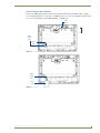
Power Via Power Over Ethernet
Power for the MXD-700 is supplied via Power Over Ethernet (PoE), utilizing an AMX-certified, capacitive
touch-compliant PoE injector or other approved AMX PoE power source. The incoming Ethernet cable should
be connected to the RJ45 port on the MXD-700 (FIG. 13 and FIG. 14).
USB
Port
Top
RJ45
Cable
Clip
RJ45
Port
FIG. 13 Rear of the MXD-700 (Landscape)
RJ45
Cable
Clip
RJ45
Port
FIG. 14 Rear of the MXD-700 (with RJ45 connection extended)
MXD/T-700 7" Modero® X Series Touch Panels
15
Installation
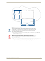
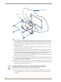
Installing the MXD-700 into a wall
The MXD-700 comes with a clear plastic backbox (designed to attach the panel to most standard wall
materials. This backbox has two locking tabs (one on top and one on bottom) to help lock the backbox to the
wall. These locking tabs are only extended AFTER the backbox is inserted into the wall. (FIG. 15).
Locking tab
Back box knockouts
MXD-700
(front)
Back box
FIG. 15 Oblique view of MXD-700 (Landscape)
When installing the backbox, make sure that the assembly is in the correct position
and in the correct place. Once the locking tabs are extended and locked into place,
removing the backbox may be difficult without having access to the back of the wall
or causing damage to the wall.
For typical mounting surfaces, such as drywall, use the locking tabs as the primary
method for securing the back box to the surface. For thin walls or solid surfaces, use
mounting screws (not included).
In order to guarantee a stable installation of the MXD-700, the thickness of the wall
material must be a minimum of .50 inches (1.27cm) and a maximum of .875 inches
(2.22cm). The mounting surface should also be smooth and flat.
The maximum recommended torque to screw in the locking tabs on the plastic back
box is 5 IN-LB [56 N-CM]. Applying excessive torque while tightening the tab screws,
such as with powered screwdrivers, can strip out the locking tabs or damage the
plastic back box.
To install the back box:
1. Prepare the area by removing any screws or nails from the drywall before beginning the cutout process.
2. For best results, use the MXD-700 Installation Template (68-5968-04) to ensure proper placement
(FIG. 16). The template is marked on one side with directions for both landscape and portrait installations
to ensure that the touch panel and back box are properly aligned.
16
MXD/T-700 7" Modero® X Series Touch Panels
Installation
4 13/16"
(12.22 cm)
4 1/16"
(10.32 cm)
6 9/16"
(16.67 cm)
7 5/16"
(18.50 cm)
FIG. 16 MXD-700 Installation Template
Using the included template to select the final placement of the back box is highly
recommended. The outside edges of the template are the same dimensions as the
touch panel, which allows you to troubleshoot possible conflicts with wall edges,
doors, and other potential obstacles.
3. After ensuring proper placement, cut out the mounting surface for the back box, using the MXD-700
Installation Template as a guide.
Making sure the actual cutout opening is slightly smaller than the provided
dimensions is highly recommended. This action provides the installer with a margin
for error if the opening needs to be expanded. Too little wall material removed is
always better than too much.
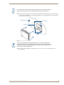
4. Thread the incoming Ethernet from their terminal locations through the surface opening (FIG. 17). Leave
enough slack in the wiring to accommodate any re-positioning of the panel.
MXD/T-700 7" Modero® X Series Touch Panels
17
Installation
Mounting Surface
Back Box
Locking
Tab
#4 Screws
Knockouts
FIG. 17 MXD-700 Back Box Installation (Landscape)
5. Remove the back box knockouts (FIG. 17) and thread the incoming wiring through the knockout holes.To
facilitate installation, thread the Ethernet cable through a bottom knockout (Landscape) or a right-side
knockout (Portrait), and the USB cable through a top knockout (Landscape) or left knockout (Portrait)
6. Thread the incoming Ethernet and USB wiring (if USB access is desired) from the surface opening and
through the knockouts.
7. Push the back box into the mounting surface. Insure that the locking tabs lie flush against the back box
and that the back box goes freely into the opening.
8. Extend the locking tabs on the sides of the back box by tightening the screws inside the box until snug.
Not all of the tabs must be extended to lock the back box in place, but extending a minimum of the top
and bottom tabs is highly recommended. Apply enough pressure to the screw head to keep the box flush
with the wall: this ensures that the locking tabs will tighten up against the inside of the wall.
The back box is clear to allow visual confirmation that the tabs have been extended and are gripping the
wall, as well as in assisting with removal if necessary.
9. For additional strength, #4 mounting screws (not included) may be secured through circular holes located
at the left and right sides of the MXD-700 (FIG. 17). In order to prevent damage to the touch panel, make
sure that these are flush with the back box.
10. Insert each connector into its corresponding location along the back of the device (FIG. 13). To reach the
RJ45 connector, gently pull it from beneath the electronics cover (FIG. 14). Attach the Ethernet cable and
gently push the connection back under the cover.
To facilitate connection of the RJ45 connector to the Ethernet cable, press the RJ45’s
cable into the RJ45 cable clip to hold it in a stable position. Make sure to remove the
cable from the cable clip before continuing the rest of the installation.
11. Test the incoming wiring by attaching the panel connections to their terminal locations and applying
power. Verify that the panel is receiving power and functioning properly to prevent repetition of the
installation.
18
MXD/T-700 7" Modero® X Series Touch Panels
Installation
Do not disconnect the connectors from the touch panel. The unit must be installed
with the attached connectors before being inserted into the mounting surface.
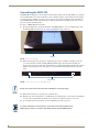
12. Latch the panel onto the top hooks on the back box and push it down (Landscape) onto the bottom snaps
or on the left side and push it to the right (Portrait) (FIG. 18). Press gently but firmly on the ends until the
snaps “click” to lock it down.
Mounting Surface
Latch Hooks
Back Box
Snaps
FIG. 18 Installing the MXD-700
If you see a gap between the panel and the back box, or feel any binding while
locking down the panel, stop immediately and verify that no cables or other items are
in the way. Do not force the panel into position, as this can cause damage to the
touch screen or the panel electronics.
13. Reconnect the terminal Ethernet and USB to their respective locations on either the Ethernet port or
NetLinx Master.
MXD/T-700 7" Modero® X Series Touch Panels
19
Installation
Uninstalling the MXD-700
The MXD-700 is held in place to the back box via latch hooks and clips on the back box (FIG. 19), securing it
to the mounting surface. In certain circumstances, such as firmware updates or other maintenance that requires
accessing the device’s USB port, the device may need to be removed from the back box. The clips that lock
down the MXD-700’s bottom edge (Landscape) or right edge (Portrait) may be unlatched in order to remove
the device from the mounting surface.
To remove an MXD-700 from its back box:
1. The bottom (Landscape) or right side (Portrait) of the MXD-700 has a series of ventilation holes along
the molding (FIG. 19). From each end, count to the fifth holes on the center row.
Molding
FIG. 19 Underside of MXD-700
2. With a stout, strong point (a push pin or straightened paper-clip, for example), carefully press into the
access holes in either end of the molding (FIG. 20) until the snap is disconnected. To facilitate the
disconnection, grasp the bottom of the panel (Landscape) or right side (Portrait) and pull gently outward
until the side of the panel is free of the snap. Use your other hand to hold stable the front of the touch
panel.
Access holes
FIG. 20 Location of access holes on MXD-700 molding
Always pull on the frame of the touch panel. NEVER pull on the glass edge.
3. When the first side is free, repeat the process with the other.
4. With the edge of the touch panel free, carefully lift up and out (Landscape) or to the left and out (Portrait)
to remove the touch panel from the back box. Be careful not to pull on the cables or connectors.
5. To reattach the panel to its back box, repeat the installation procedure on page 19.
For further information on this procedure, please refer to the video available at the
AMXconfigure channel on YouTube: http://www.youtube.com/user/AMXconfigure
20
MXD/T-700 7" Modero® X Series Touch Panels
Configuration and Programming
Configuration and Programming
Programming the MXT-700 and MXD-700 require the use of the latest versions of
NetLinx Studio and TPDesign 4, both available at www.amx.com.
Modero X Series Programming Guide
Information on Settings pages, panel configuration, and programming is included in the Modero X Series
Programming Guide, available at www.amx.com.
MXD/T-700 7" Modero® X Series Touch Panels
21
Configuration and Programming
22
MXD/T-700 7" Modero® X Series Touch Panels
Upgrading Firmware
Upgrading Firmware
Overview
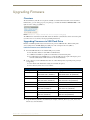
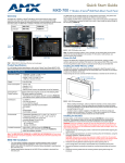
The latest firmware (*.kit) file for each panel is available to download from www.amx.com. To download
firmware files, go to the catalog page for your panel type, and click the link under "Firmware Files" on the
right side of the catalog page (FIG. 21):
FIG. 21 www.amx.com - example "Firmware Files" link on a touch panel catalog page
The ZIP file that is downloaded via this link contains the firmware (*.kit) file that can be loaded on the panel
(as well as release notes and any relevant programming instructions).
Upgrading Firmware via USB Flash Drive
Firmware and TPDesign4 files may be transferred to the panel via USB flash drive. When looking at the
device from the front, the MXT-700 has two USB ports on the rear right of the device (FIG. 3).
Load the Firmware on a USB Flash Drive
1. Insert the USB flash drive in an available USB port on your PC.
The flash drive must be in either FAT32 or FAT16 format.
32GB is the maximum acceptable size for flash drives used with touch panels.
For wall-mounted panels (MXD-xxx), accessing the USB ports may require removing the panel
from the wall mount (if a USB extension was not already installed).
2. Create a directory on the USB flash drive with one of the following names, depending on the panel you
are upgrading:
Note that the name must match exactly (do not include the quotes).
These directory names are not case-sensitive:
Directory Names for Firmware Files - by Touch Panel Type
Directory Name
"MXD-2000XL-PAN"
Panel Type(s)
MXD-2000XL-PAN-P (FG5968-05)
MXD-2000XL-PAN-P-NC (FG5968-33)
MXD-2000XL-PAN-L (FG5968-11)
MXD-2000XL-PAN-L-NC (FG5968-34)
"MXT-2000XL-PAN"
MXT-2000XL-PAN (FG5968-01)
MXT-2000XL-PAN-NC (FG5968-32)
"MXD-1900L-PAN"
MXD-1900L-PAN-P (FG5968-06)
MXD-1900L-PAN-P-NC (FG5968-22)
MXD-1900L-PAN-L (FG5968-12)
MXD-1900L-PAN-L-NC (FG5968-23)
"MXT-1900L-PAN"
MXT-1900L-PAN (FG5968-02)
MXT-1900L-PAN-NC (FG5968-21)
"MXT-1000"
MXT-1000 (FG5968-03)
MXT-1000-NC (FG5968-24)
"MXD-1000"
MXD-1000-P (FG5968-07)
MXD-1000-P-NC (FG5968-25)
MXD-1000-L (FG5968-13)
MXD-1000-L-NC (FG5968-26)
"MXT-700"
MXT-700 (FG5968-04)
MXT-700-NC (FG5968-27)
"MXD-700"
MXD-700-P (FG5968-08)
MXD-700-P-NC (FG5968-28)
MXD-700-L (FG5968-14)
MXD-700-L-NC (FG5968-29)
"MXD-430"
MXD-430-P (FG5968-15)
3. Copy the firmware (.kit) file to be transferred (for example, "SW5968_ModeroX_v2_103_52.kit") into
this directory on the flash drive.
MXD/T-700 7" Modero® X Series Touch Panels
23
Upgrading Firmware
Make sure this is the only .kit file in this directory - if not, the latest version will be
used.
4. Eject or unmount the flash drive from the PC.
Transfer the Firmware File From the Flash Drive to the Touch Panel
1. Connect the USB Flash Drive to one of the USB Type A ports on the panel.
The Micro USB port cannot be used for firmware upgrades.
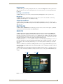
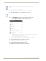
2. Go to the Install Firmware setup page (Configuration->Admin->Install Firmware):
a. Press and hold the Sleep button for 3 seconds to open the Settings page.
FIG. 22 Settings page
b. From the Settings page, select the Configuration page. This may require entering a password.
c. From the Configuration page, select Admin.
d. From the Admin Configuration page, select Install Firmware.
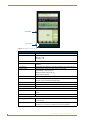
3. In the Firmware Installation page, select New to install new firmware from external disk.
4. The popup page displays the name of the firmware file (for example,
"SW5968_ModeroX_v2_103_52.kit").
5. Select Yes, and follow the directions displayed on the popup.
6. Once the panel reboots it will perform the firmware upgrade.
After the upgrade, the unit contains the newly loaded version of firmware.
24
MXD/T-700 7" Modero® X Series Touch Panels
Upgrading Firmware
Upgrading from Previous Firmware
The MXT-700 and MXD-700 allow the option to revert the device to the previous firmware run before an
upgrade. To upgrade the device from previously loaded firmware:
1. From the Settings page, select the Configuration page.
2. From the Configuration page, select Admin.
3. From the Admin Configuration page, select Install Firmware.
4. In the Firmware Installation page, select Previous.
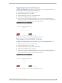
5. The Confirmation Dialog box (FIG. 23) will ask “Are you sure you want to install the following
firmware?” The option to choose Yes will be enabled after five seconds. Press Yes to load the firmware
listed, and No to return to the Firmware Installation popup window.
FIG. 23 Previous Firmware installation confirmation dialog
6. If you choose Yes, the device will retrieve the files and then reboot.
Returning to Factory Default Firmware
The MXT-700 and MXD-700 allow the option to return the device to its original factory default firmware,
which may be necessary in certain situations. To return the device to its factory default firmware:
1. From the Settings page, select the Configuration page.
2. From the Configuration page, select Admin.
3. From the Admin Configuration page, select Install Firmware.
4. In the Firmware Installation page, select Factory.
5. The Confirmation Dialog box (FIG. 23) will ask “Are you sure you want to install the following
firmware?” The option to choose Yes will be enabled after five seconds. Press Yes to load the firmware
listed, and No to return to the Firmware Installation popup window.
FIG. 24 Previous Firmware installation confirmation dialog box
6. If you choose Yes, the device will retrieve the files and then reboot.
MXD/T-700 7" Modero® X Series Touch Panels
25
Upgrading Firmware
Upgrading Firmware Via NetLinx Studio
The MXT-700 and MXD-700 use an Ethernet connection for programming, firmware updates, and touch panel
file transfer via NetLinx Studio. If you have access to the panel’s network, you may transfer files directly to the
panel through NetLinx Studio
Firmware upgrades cannot be made through an Ethernet-connected PC to the touch
panel, unless that PC is connected to the panel’s network. Upgrades cannot be made
with NetLinx Studio through a USB connection to the panel from a PC. For more
information on firmware transfers, please refer to the online help in NetLinx Studio.
To upgrade firmware via NetLinx Studio:
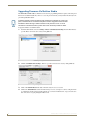
1. Launch NetLinx Studio and select Settings > Master Communication Settings from the Main menu to
open the Master Communication Settings dialog (FIG. 25)
FIG. 25 Master Communications Settings dialog box
2. Click the Communications Settings... button to open the Communications Settings dialog (FIG. 26).
FIG. 26 Communications Settings dialog box
3. Click on the NetLinx Master radio button from the Platform Selection section.
4. Click on the Virtual Master radio box from the Transport Connection Option section to configure the PC
to communicate directly with a panel. Everything else, such as the Authentication, is greyed-out because
this connection is not going through the Master’s UI.
26
MXD/T-700 7" Modero® X Series Touch Panels
Upgrading Firmware
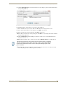
5. Click the Edit Settings button on the Communications Settings dialog to open the Virtual NetLinx Master
Settings dialog (FIG. 27).
FIG. 27 Virtual NetLinx Master Settings
6. Within this dialog, enter the Master System number. The default is 1.
7. In the Available Connections section, click on the IP address for the touch panel to select it.
8. In the Virtual NetLinx Master Settings dialog box, click OK to close the box.
9. In the Communications Settings dialog box, click OK to close the box.
10. In the Master Communications Settings dialog box, click OK to save your settings and return to the main
NetLinx Studio application.
11. Click the OnLine Tree tab in the Workspace window to view the devices on the Virtual System. The
default System value is 1.
12. Right-click on the Empty Device Tree/System entry and select Refresh System to re-populate the list.
The panel will not appear as a device below the virtual system number, in the Online
Tree tab, until both the system number used in step 14 for the Virtual NetLinx Master
is entered into the Master Connection section of the System Settings page and the
panel is restarted.
13. The OnLine Tree should now display the connection to the device. The Connection Status Icon on the
device may take up to five seconds to register the connection.
MXD/T-700 7" Modero® X Series Touch Panels
27
Upgrading Firmware
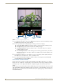
Viewing devices on the Virtual System
1. After the Communication Verification dialog window verifies active communication between the Virtual
Master and the panel, click the Online Tree tab in the Workspace window (FIG. 28) to view the devices
on the Virtual System. The default System value is 1.
2. Right-click on the System entry (FIG. 28) and select Refresh System to re-populate the list. Verify the
panel appears in the Online Tree tab of the Workspace window.
Virtual Master firmware
version and device number
Panel firmware version
and device number
FIG. 28 NetLinx Workspace window (showing panel connection via a Virtual NetLinx Master)
Downloading firmware
The panel-specific firmware is shown on the right of the listed panel.
Download the latest firmware file from www.amx.com and then save the Kit file to
your computer. Note that each Kit file is intended for download to its corresponding
panel. In some cases, several Kit files may be included in a .zip file; extract the .zip
file to access the required Kit file.
1. If the panel firmware version is not the latest available; locate the latest firmware file from
www.amx.com.
2. Click on the desired Kit file link and after accepting the Licensing Agreement, verify download of the
Modero Kit file to a known location.
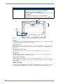
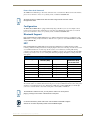
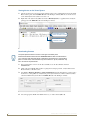
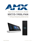
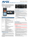
3. Select Tools > Firmware Transfers > Send to NetLinx Device from the main menu to open the Send to
NetLinx Device dialog (FIG. 29). Verify that the panel’s System and Device number values match those
values listed within the System folder in the Online Tree tab of the Workspace window.
FIG. 29 Send to NetLinx Device dialog window
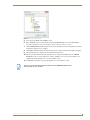
4. Select the appropriate Kit file from within the Browse for Folder window (FIG. 30).
28
MXD/T-700 7" Modero® X Series Touch Panels
Upgrading Firmware
FIG. 30 Browse for Folder window
5. Select the panel’s Kit file from the Files section.
6. Enter the Device value associated with the panel and the System number associated with the Master
(listed in the OnLine Tree tab of the Workspace window). The Port field is greyed-out.
7. Click the Reboot Device checkbox if it is not already checked. This causes the touch panel to reboot after
the firmware update process is complete.
8. Click Send to begin the transfer. The file transfer progress is indicated on the bottom-right of the dialog.
9. After the file transfer is complete, the panel will automatically reboot.
10. After the panel has finished rebooting, right-click the associated System number and select Refresh
System. This causes a refresh of all project systems, establishes a new connection to the Master, and
populates the System list with devices on your particular system.
11. Confirm that the panel has been properly updated to the correct firmware version.
Verify you have downloaded the latest firmware file from www.amx.com and then
save the Kit file to your computer.
MXD/T-700 7" Modero® X Series Touch Panels
29
Upgrading Firmware
30
MXD/T-700 7" Modero® X Series Touch Panels
Appendix: Troubleshooting
Appendix: Troubleshooting
Overview
This section describes the solutions to possible hardware/firmware issues that could arise during the common
operation of a Modero X touch panel.
Panel Doesn’t Respond To Touches
Symptom: The device either does not respond to touches on the touch screen or does not register the touch as
being in the correct area of the screen.
If the screen is off:
The device may be in Display Sleep Mode. Press and hold the Sleep button to wake up the panel.
The device may not be connected to power. Verify that the power source is connected to the device
and receiving power.
Panel Isn’t Appearing In The Online Tree Tab
1. Verify that the System number is the same on both the NetLinx Project Navigator window and the System
Settings page on the device.
2. Verify the proper NetLinx Master IP and connection methods entered into the Master Connection section
of the System Settings page.
Can’t Connect To a NetLinx Master
Symptom: I can’t seem to connect to a NetLinx Master using NetLinx Studio.
Select Settings > Master Comm Settings > Communication Settings > Settings (for TCP/IP), and uncheck the
"Automatically Ping the Master Controller to ensure availability".
The pinging is to determine if the Master is available and to reply with a connection failure instantly if it is not.
Without using the ping feature, a connection may still be attempted, but a failure will take longer to be
recognized.
If you are trying to connect to a Master controller that is behind a firewall, you may
have to uncheck this option. Most firewalls will not allow ping requests to pass
through for security reasons.
When connecting to a NetLinx Master controller via TCP/IP, the program will first try to ping the controller
before attempting a connection. Pinging a device is relatively fast and will determine if the device is off-line,
or if the TCP/IP address that was entered was incorrect.
If you decide not to ping for availability and the controller is off-line, or you have an incorrect TCP/IP address,
the program will try for 30-45 seconds to establish a connection.
Only One Modero Panel In My System Shows Up
Symptom: I have more than one Modero panel connected to my System Master and only one shows up.
Multiple NetLinx Compatible devices can be associated for use with a single Master. If the user does not
assign a device number, one will be assigned automatically to the panel. When using multiple panels, different
Device Number values have to be assigned to each panel.
1. Press and hold the Sleep button to open the Settings page.
2. Press the Protected button, enter 1988 into the on-screen Keypad’s password field, and press Done when
finished.
3. Enter a Device Number value for the panel into the Device Number Keypad. The range is from 1 - 32000.
MXD/T-700 7" Modero® X Series Touch Panels
31
Appendix: Troubleshooting
32
MXD/T-700 7" Modero® X Series Touch Panels
Appendix - Troubleshooting
MXD/T-700 7" Modero® X Series Touch Panels
33
AMX. All rights reserved. AMX and the AMX logo are registered trademarks of AMX. AMX reserves the right to alter specifications without notice at any time.
©2012
9/12
It’s Your World - Take Control™
3000 RESEARCH DRIVE, RICHARDSON, TX 75082 USA • 800.222.0193 • 469.624.8000 • 469-624-7153 fax • 800.932.6993 technical support • www.amx.com