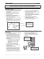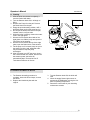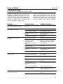
1
Installation, Operation & Maintenance Manual
PRESSURE STEAMERS
SERIES: PGM, PEM, PSM, PDM, PDL-2/3
260APC-A
Operator’s Manual
P/N-260APC-A
Table of Contents
INSTALLATION
3
Correct Installation
3
Water Quality
3
Drain Line Connection
4
Installation Safety
4
Installation Instructions
5
Installation checks
5
Gauge Pressure Reading with No Steam Flow* (Static Pressure)
7
OPERATION
7
Controls and Controls Panels
7
Steam Generator Controls
7
Start-up and Preheat
8
Cooking Operations
8
Startup and Preheat
9
Cooking Operation
9
Boiler Shutdown
9
Care and Cleaning
9
MAINTENANCE
Preventative Maintenance-Descaling Instructions
TROUBLESHOOTING
10
11
15
Operators Troubleshooting Guide
16
Troubleshooting Notes
16
PRESSURE STEAMER COOKING INFORMATION
17
______________________________________________________________________________2
Operator’s Manual
P/N-260APC-A
Installation
CORRECT INSTALLATION
You have purchased the finest Steam Cooking Equipment
made. The following information we know will increase the
productivity and life span of the equipment.
Every product needs proper installation and with a
steamer it is critical. The following is some important
information you should check on before and during
installation of the equipment.
Water
The quality of water you put into the steam generator is
important. Poor quality water will create generator problems.
Water is no longer just plain and simple. Water has many
natural ingredients in it. These are called Total Dissolved
Solids, or TDS. This includes calcium, iron, and other
minerals in the water that collect in the steam generator
Because of the droughts in many areas, water and TDS's
are being pumped up from the bottom of the water
systems. If these TDS are not pre-filtered out or cleaned
out with a regular preventive maintenance program, your
steam generator could deteriorate and develop holes.
CHLORIDE is another chemical in our water creating
many problems with all steam generators. When the generator creates steam from the water it also carries the
chloride gas with it. These chlorides begin to eat away the
inside of the generator and follow the steam into the
compartments causing a rusting action (oxidation) as it
goes along.
A CARBON OR CHARCOAL FILTER must be installed on
the incoming water line to the steamer if the chlorine is
over 30 parts per million. These filters will remove the
chloride.
The WATER QUALITY
STEAMER are as follows:
Total Dissolved Solids
Total Alkalinity
Silica
Chlorides
pH Factor
REQUIREMENTS
for
your
less than 60 parts per million
less than 20 parts per million
less than 13 parts per million
less than 30 parts per million
greater than 7.5
Drain Line Connection
A proper drain line connection is important. If the drain
line is clogged it can create a back up of pressure causing
extreme and costly repairs.
Figure 1. Drain Connections
If the drain line is not large enough, not open at the end,
or does not have a gravity flow; pressure and hot water
will back up into the compartments. If any of these conditions exist and hot water does back up into the compartment someone could be seriously burned and injured.
This can happen even with a correct installation if a drain
cleaner is not used on a regular basis.
An open and free flowing drain line IS REQUIRED for the
proper cooking performance of a CONVECTION
STEAMER. It helps create a swirling action around the
products being cooked. This movement of hot steam
around the product is your CONVECTION STEAM
COOKING.
DO NOT INSTALL UNIT OVER A FLOOR DRAIN. If it
becomes an absolute must, using an 18.' stainless steel
or aluminum pan turn it over and cut a notch in the side
wall to fit over the drain line. Place the pan directly over
the drain opening- DO NOT SEAL TO THE FLOOR. The
steam from the drain line will collect on the under side and
condense into the drain opening.
DO
NOT
INSTALL
GAS
UNITS
ON
FLAMMABLEFLOORS OR NEAR WALLS. A flammable
floor or wall is any material such as wood, linoleum, or
vinyl that is easily ignitable and bums rapidly.
The intent of these instructions is to provide meaningful
information, which will help you obtain many years of
production. Before installing the steamer, please read
those instructions carefully to maintain your safety and
warranty.
______________________________________________________________________________
3
Operator’s Manual
INSTALLATION SAFETY
WARNING
Qualified installation personnel, working to all applicable
local and national codes must accomplish installation of
this equipment. Improper installation of this product could
cause or damage.
Do not store or use gasoline or other flammable Vapors
and liquids in the vicinity of this or any other appliance.
The flooring that will be directly under the boiler must also
be made of a noncombustible material.
Cleveland Range equipment is designed and built to comply with applicable standards for manufacturers. Included
among those certification agencies which have approved
the safety of the equipment design and construction:
UL, A.G.A., NSF ASME, CSA, CGA, and others.
Cleveland Range equipment is designed and certified for
safe operation only when permanently installed in accordance with local and I or national codes. Many local codes
exist and it is the responsibility of the owner and installer
to comply with these codes
In no event shall Cleveland Range assume any liability for
consequential damage or injury resulting from installations
which is not in strict compliance with our installation
instructions. Specifically, Cleveland Range will not
assume any liability for damage resulting from improper
installation of equipment including, but not limited to,
temporary or mobile installations
INSTALLATION INSTRUCTIONS
1. These instructions must be retained by the owner/user
for future reference. Gas-fired boilers are only to be installed in noncombustible areas that have provisions for
s
adequate air supply. The term "boiler’ will be used synonymously with "steam generator".
2. Position: For proper operation and drainage, the equipment must be level. It should be placed next to an open
floor drain. DO NOT POSITION THE UNIT DIRECTLY
ABOVE WE FLOOR DRAIN. Observe all clearance requirements to provide air supply for proper operation,
as well as sufficient clearance for servicing. The
surrounding area must be free and clear of
combustibles. Dimensions and clearance specifications
are shown on the specification sheet.
3. Install in accordance with local codes and/or the National
Electric
Code
ANSI/NFPA
No.70-1987.
Installation in Canada must be in accordance with
Canadian Electrical Code CSA Standard C22.1. The
installer A wiring diagram is provided inside the
base cabinet must ground equipment that is
connected to electricity.
P/N-260APC-A
WARNING
INJURY TO PERSONNEL AND EQUIPMENT DAMAGE
May result from an improper drain connection. No
connection lines are to be under the unit
4. Drain Line. The drain line outlet discharges exhaust
steam and hot condensate. Connect 1-1/2-inch IPS
piping (or larger) to extend the drain line to a nearby
open floor drain. Up to two elbows and six feet of 1-1/2inch IFS (or larger) extension pipe should be connected
to the drain termination. No more than two pieces of
Cleveland Range Equipment should be connected to
one common drain line. The extension piping must have
a gravity flow and vent freely to the air. This drain outlet
must be free-vented to avoid the creation of
backpressure in the steamer cooking compartments. To
ensure a vented drain line, DO NOT UNDER ANY
CIRCUMSTANCES, CONNECT THE DRAIN OUTLET
DIRECTLY TO THE FLOOR DRAIN OR SEWER LINE.
Do not run the drain line discharge into PVC drain
piping or any other drain piping material not capable of
sustaining 180' F operation.
5. Water Supply. Connect COLD water plumbing to the
line strainer (Never conned hot water to the condensate
water fill line strainer) Constant flow pressure must be
maintained between 35 and 60 psi, and not experience
a pressure drop below 35 psi when other appliances
are used. If the water pressure exceeds 60 psi, a
pressure-reducing valve must be installed in the water
supply plumbing to reduce the water pressure to less
than 60 psi. Locations and pressure data are shown on
the specification sheet. 3/S-inch IPS plumbing is
sufficient for water supply lines up to 20 feet in length,
but water supply lines longer than 20 feet should be at
least 1/2-inch IPS. Flush water supply lines thoroughly
before connecting them to the unit. Use water, which is
low in total dissolved solids content and low in gas
content to prevent internal scaling, pitting and corrosion
of the steam generator, and carry-over of minerals into
the steam. Water, which is fit to drink, can still contain
highly detrimental impurities.
NOTE: If equipped with a kettle and kettle water fill
swing spout, 3/8-inch (10 mm) hot and/or
cold-water connection(s) will be required at
the swing spout valve.
6. Turn on the cold water supply to the unit Ensure that
the manual water valve, inside the base cabinet is
open.
7. Fuel Supply. Connect the primary fuel supply in accordance with the following instructions. Location and other
data are shown on the specification sheet.
For Gas-Fired Steam Generators: Post in a prominent
location, instructions to be followed in the event the user
smells gas. This information shall be obtained by the
consulting the local gas supplier.
______________________________________________________________________________
4
Operator’s Manual
Install a sediment trap (drip leg) in the gas supply line,
and then connect gas supply piping to the boiler gas valve
piping. GAS-FIRED EQUIPMENT IS DESIGNED FOR
INSTALLATION
ONLY
IN
NONCOMBUSJJBLE
LOCATIONS. THIS INCLUDES THE FLOOR-INC THAT
WILL BE DIRECTLY UNDER THE EQUIPMENT Location,
plumbing size, and pressure data are shown on the
specification sheet. Boilers rated at less than 225,000 Btu
require 3/4-inch 'PS gas supply piping, and boilers rated
at 225,000 Btu or more require 1-inch II'S gas supply
piping. Natural gas pressure must be between 4" -14"
water column and LP gas supply pressure must be
between 12" - 14" water column. NEVER EXCEED 14"
WATER COLUMN (1/2 psi) GAS PRESSURE. If the gas
supply pressure exceeds 14" water column, a pressureregulating valve must be installed in the gas plumbing to
reduce the gas pressure to less than 14" water column.
Installation must be in accordance with local codes, or in
the absence of local codes, with the National Fuel Gas
Code, ANSI Z223.1-1984. Installation in Canada must be
in accordance with Installation codes for Gas Burning
Appliances and Equipment B149.1 and B149.2. Use a gas
pipe joint compound, which is resistant to LP gas. Turn
the gas valve control knob to ON (the word "on" the knob
will be opposite the index on the valve's body). Test all
pipe joints for leaks with soap and water solutions. Never
obstruct the flow of combustion and ventilation air
Observe all clearance requirements to provide adequate
air openings into the combustion chamber. The appliance
and it's individual shutoff valve must be disconnected from
the gas supply piping system during any pressure testing
of that system at test pressures in excess of 14" water
column (1/2 psi or 3.45 k}'a). The appliance must be
isolated from the gas supply piping system at test
pressures equal to or less than 14" water column (1/2 psi
or 3.45 kpa). A permanent 115-volt electrical connection is
required at the junction box. The junction box location is
shown on the specification sheet. The installer must
electrically ground the unit.
For Electric-Powered Steam Generators: Connect
electric power: location and data are shown on the
specification sheet. Provide connection as required by the
unit, either directly to the single contactor, or to the
terminal block (when equipped with multiple contactors).
Electric supply must match power requirements specified
on the data plate inside the base cabinet. The copper
wiring size must be adequate to carry the required current
at the rated voltage. A separate fused disconnect switch
must be supplied and installed. The installer must
electrically ground the unit
For Steam Coil Steam Generators: Connect steam
supply piping to the input side of the steam coil. Location
and pressure data are shown on the specification sheet.
Incoming steam pressure must be regulated between 35
and 45 psi. A 3 /4inch strainer, equipped with a 20 mesh
stainless steel screen, must be supplied and installed at
the incoming steam connection point. Flush the steam
P/N-260APC-A
line thoroughly before connecting it to the boiler. To
ensure an adequate volume of steam, the branch steam
supply line must be 3/~inch 'PS minimum. Connect the
inverted bucket trap to the outlet end of the steam coil. Pill
the trap with water before installing it. A permanent 115volt electrical connection is required at the junction box.
The junction box location is shown on the specification
sheet. The installer must electrically ground the unit.
For Direct-Steam Connected Steamers and Kettles:
Connect steam supply piping to the input side of the line
strainer. Location and pressure data are shown on the
specification sheet. Flush the steam line thoroughly
before connecting it to the steamer. To ensure an
adequate volume of steam, the branch steam supply line
must be 3/4 inch 'PSI 'minimum. Direct-steam-connected
kettles require 1 /2-inch 'PS pipe if the kettle total capacity
is 20 gallons or less, and 3/4-inch 'PS pipe if the total
capacity exceeds 20 gallons.) A permanent 115-volt
electrical connection is required at the junction box. The
junction box location is shown on the specification sheet.
The installer must electrically ground the unit
INSTALLATION CHECKS
Proper operation of the Cleveland Convection Steamer is
dependent upon proper installation. After the steamer has
been installed, a few quick checks could save
unnecessary service calls.
1.
The unit must be level.
2.
The Convection Steamer requires a cold water
connection for proper efficient operation. DO NOT
USE HOT WATER. The cold water must be
connected to the line strainer, located at the front
lower right of the steamer base.
3.
Check that the manual water supply valve is open.
4.
Check all water supply lines and valves for leaks.
5.
Check that the water supply pressure and water
quality meets the requirements of installation
paragraphs.
6.
On electrical units, verify that the supply voltage
meets the voltage requirements on the rating plate
inside the base cabinet and the voltage shown on the
packing slip. Verify that the unit is protected with a
separate fused disconnect and is properly grounded
in accordance with the National Electric Code.
On gas, steam coil and dir'cct4team-connected units
7.
On all gas, steam-coil, and direct steam connected
units, verify that there is a 115-Volt connection at the
handy-box located on the left side of the base.
______________________________________________________________________________
5
Operator’s Manual
8. On all steamcoil units, the incoming steam pressure
must be 35-50 psi. Less than 35 will not effectively
operate the unit. Pressure in excess of 50 psi must be
reduced (with a pressure-reducing valve) to 35-50 psi.
9.
Check that the drain lines meet installation
requirements specified in installation paragraph 4
WARNING
INJURY TP PERSONNEL AND EQUIPMENT DAMAGE
may result from an improper installation.
10. After completing checks 1 through 9, correct any
deficiencies refer to the Start-Up and Pre heat
instructions in the Operation section. Verify that the unit
operates properly, make checks 11 and 12.
11.Check to ensure that the water in the boiler sight
gauge glass automatically stays about 1/3 full when
boiler is started up and operated.
12. Check to ensure that the steam pressure gauge
registers 10 psi. The steam pressure is factory-adjusted
to 10 psi
P/N-260APC-A
Factory setting may shift due to shaking in transit and
resetting will be required after installation. Proper adjustments and maintenance procedures am detailed on a
separate data sheet entitled "Steam Pressure Adjustments." Adjustments should be made only by qualified
service personnel- the factory pressure settings shown in
the accompanying chart should never be exceeded.
GAUGE PRESSURE READING WITH
NO STEAM FLOW* (STATIC PRESSURE)
Self-Contained Steam Generator; Gas or Electric
Operating Pressure Switch
10 psi
High Limit Safety Pressure Switch
15 psi
Self-Contained Steam Coil Generator
Operating Pressure Switch
High Limit Safety Pressure Switch
Steam Supply Pressure Range
10 psi
15psi
35-45 psi
Direct-Connect (to House Steam Supply)
Steamer Pressure Reducing Valve
10 psi
Steam Supply Pressure Range
1545 psi
** With or without kettle
______________________________________________________________________________
6
Operator’s Manual
OPERATION
Operation of the Cleveland Range Convection Steamer is
very easy. Each operator should read and understand the
following procedures to effectively start, operate, and shut
down the steamer each day. The owner(s) and operator(s)
of this equipment should be aware that live steam could
cause serious injuries, pay particular attention to the
WARNINGS in this text. These instructions are to be
retained by the owner(s)) and operator(s) for future
reference.
Note:
These instructions pertain to pressure steamers
equipped with a steam generator (boiler). For
pressure steamers direct-connected to a remote
(in-house) steam source. Disregard those
instructions, which pertain solely to a selfcontained boiler.
START-UP AND PREHEAT
WARNING
Do not attempt to start or operate the Pressure Steamers
during a power failure. Critical safety circuits are not
energized, and serious injury to personnel or damage to
equipment may result.
P/N-260APC-A
The red indicator light in the POWER rocker switch
turns on and the steam generator begins to fill with
water units takes about 5 minutes.
b. When the water level in the steam generator reaches
a safe operating level, the amber light in the STEAM
momentary switch turns on. Whenever the amber light
is on, the heaters, steam supply, or burners are off,
and no steam is being generated. The energy source
(electric, gas, etc.) cannot be activated until the boiler
contains sufficient water, indicated by the amber light.
c. Press the STEAM (amber colored) momentary switch
to produce steam in the boiler this activates the energy
source (electric heaters, gas burners, or steam solenoid valve) and the amber light turns off. The STEAM
switch must be pressed to restart the steamer after it is
shut off for any reason (including a brief power
interruption). No attempt should be made to operate
the equipment during a power failure.
NOTE: For steamers with built-in gas-fired boilers: If the
burners fail to ignite in four seconds, a safety
circuit energizes the system. In this event toggle
the POWER rocker switch to the OFF position
and back to the ON position. The amber light in
the STEAM momentary switch lights. Wait five
minutes, and then press the STEAM momentary
switch to start the burner ignition cycle once
again.
d. About 15 minutes after starting the boiler in step C; the
steam pressure gauge on the unit base should register
10 psi.
2. To preheat, close and latch the door securely Turn the
bar handle clockwise until the gasket just touches the
compartment face.
Boiler Controls
1. Start the steam supply. The steam is either an integral
steam generator boiler) built into the base unit, or an
external steam supply.
•
For units without a built-in boiler, refer to the start-up
procedures for the external steam supply and be sure
it is running properly. As soon as the pressure gauge
On the Pressure Steamer front console is a pressure
gauge, when it registers 10 psi, steamer preheating may
begin. Skip the remainder of step I, and begin step 2.
•
For units with a built-in boiler, fill the boiler with water
and start the steam generator as described in step a.
through d. below.
a. Press the ON end of the POWER on-off rocker switch
located next to the steam pressure gauge (Figure 2).
3. Start the steam supply by pulling the steam valve
handle out' The handle is located to the immediate left
of the door latch. set the time for 5 minutes. The
standard mechanical timer must be turned past 10
minutes to wind the spring. then set the timer for S
minutes. This is not necessary with the optional
automatic timer. At the start the compartment
thermostatic traps will release air and wet steam for
about two minutes, then shut of. Throughout the
preheating or cooking cycles, the traps will open and
close periodically. venting cooler steam and condensate
4. Seal the compartment door by turning the bar handle
clockwise just until steam leakage stops. DO NOT
OVERTIGHTEN.
5. At the completion of the 5-minute preheating cycle, the
timer's bell will ring. If fitted with an optional automatic
timer; turning the knob to "Or. will stop the bell. Push
______________________________________________________________________________
7
Operator’s Manual
the steam valve handle in slowly. all the way. This
shuts off the steam supply and also depressurizes and
drains the compartment, which takes about 2 minutes.
Note:
The automatic timer shuts an The steam
automatically; the mechanical timer does not
Neither timer depressurizes and drains the
compartment
WARNING
WAIT AT LEAST TWO MINUTES FOR THE
COMPARTMENT (S) TO DEPRESSURIZE AND DRAIN
BEFORE OPENING THE COMPARTMENT DOOR.
6. To open the compartment door. turn the bar handle
counter-clockwise. Do not attempt to disengage the
door arm latch. When the compartment has
depressurized and drained completely; the door will
open slightly and come to rest against the door arm
latch. WARNING: If at this point the door does not open
partially by itself, it is a sign that the drain line is
blocked. Do not attempt to open the door. Retighten the
bar handle and then call a serviceman to open the door
and unblock the drain line (Seepage 3. item #2,
regarding drain)
COOKING OPERATION
Check the cooking compartment to ensure it is warm. If ft
is cool. Perform the steps for preheating
Place the pan(s) of food into the cooking compartment by
sliding the pan(s) into the slide rack for optimum steam
heat transfer. and therefore, a higher quality food product
is achieved when shallow. perforated, uncovered pans are
used. if pans must be covered. use only stainless steel
pan lids designed for use with the pan racks. Do not cover
pans with aluminum foil or plastic wrap, as they may fall
out of the pan and clog the drain. A clogged drain may
cause an' accumulation of hot water in the cooking
compartment which could cause injury when the door is
opened.
Boiler Shutdown
The red-lighted power switch must be shut off for 3 minutes a minimum of once every 8 hours to automatically
drain highly mineralized water from the boiler, which reduces the formation of scale. See step J in CARE AND
CLEANING instructions, which follow.
CARE AND CLEANING
The Cleveland Convection Steamer must he cleaned
regularly to maintain its fast, efficient cooking
performance, and to ensure its continued safe, reliable
operation.
P/N-260APC-A
1. The boiler must be drained (Blowdown) after a maximum of 8 hours of use. If the boiler feedwater contains
more than 60 parts per million of total dissolved solids,
the boiler must have a Blowdown more often, the frequency depending upon the mineral content of the
feedwater Blowdown means the boiler must be drained
under pressure.
THE BOILER BLOWDOWN IS PERFORMED BY SIMPLY SHUTTING OFF THE STEAMER'S REDLIGHTEDPOWER SWITCH WHILE THE BOILER IS
AT NORMAL 10 PSI OPERATING PRESSURE.
WHEN THEBOTTOM OF THE POWER ROCKER
SWITCH ISPRESSED, ITS RED LIGHT GOES OUT,
AND THE DRAIN VALVE AUTOMATICALLY OPENS,
DRAINING THE BOILER. AUTOMATICALLY TIMED
DRAIN WATER CONDENSER WILL PLUSH THE
DRAIN FOR 3 MINUTES THEN SHUT OFF. AITER 3
MINUTES THE STEAMER IS READY TO BE RESTARTED.
When steam is produced, the water in the boiler is
being distilled. During this process, the minerals that
come into the boiler with the water; remain in the
boiler as the water boils away as steam. When
allowed to accumulate, the water becomes highly
mineralized, which results in erratic operation, lime
build-up, corrosion, and premature electric heater
failures. In some cases, complete boiler
replacement becomes necessary, which is
extremely expensive. By draining the boiler under
pressure, most sediment present will be flushed
down the drain.
2. The steamer is equipped with a drain in the back of
the cooking compartment. No compartment should
be o~ crated without the drain screen in place. This
screen prevents large food particles from entering
and possibly plugging the drain line. Any restriction
of the drain line may cause a slight build-up of
backpressure in the compartment, resulting in steam
leaks around the door gasket. It also may adversely
affect the convection action of the steam in the
compartment, which is critical to optimum
performance. Pouring USDA approved drain cleaner
through the compartment drains once a week will
help to ensure an open drain. An auger or "snake”
may be safely used to clear obstructions in the
compartment drains. Do not use a power auger, as
damage to the plastic drain system will result.
With the steamer off, open the cooking compartment
doors and allows the steamer to cool before
cleaning the cooking compartments and their
components.
3. At the end of each day's operation, wash the pan
slides door gaskets, and compartment interiors with
mild detergent and warm water, either by hand or in
a dishwasher Rinse thoroughly with clear water.
______________________________________________________________________________
8
Operator’s Manual
P/N-260APC-A
Rinse water should drain freely through the
compartment drain openings. If it does not, the drain
must be cleaned before using the steamer.
4. To prolong door gasket life, always
compartment door ajar when not in use.
leave
5. Exterior Care: Allow steamer to cool before washing.
Use the same cleaners and cleaning procedures as
for other kitchen surfaces of stainless steel and
aluminum. Mild soapy water, with a dear water rinse,
is recommended. DO NOT ALLOW WATER TO
RUN INTO ELECTRICAL Controls. Always turn off
equipment power before using water to wash
equipment. Do not hose down the steamer!
WARNING
Do not store gasoline or other flammable vapors and
liquids in the vicinity of this or any other appliance.
A. DAILY
1. Using a NON-CHLORINE DETERGENT
a. Wipe out the interior of the compartments
b. Wipe the face of the compartments
c. Rinse the pan slides
d. When the steamer is not cooking, leave the door open
resting against the door latch.
e. Wipe down the gaskets to prevent sticking
5. WEEKLY
1. Check the door gasket for wear and reverse or replace
the gasket when needed.
2. Pour a liquid chemical descaler down the back of each
compartment drain.
C. MONTHLY
1. Every 3 to 4 months the generator should be opened
and checked for mineral build up or Chloride corrosion.
MAINTENANCE
Periodically, a qualified serviceman should be summoned
for routine preventive maintenance.
1. The Blowdown procedure will not completely remove
the mineral deposits that adhere to the top of the boiler. A
boiler treatment specialist should do a chemical
descaling. This should be done 4 times a year in average
water conditions, but in poor water areas it may be
needed more often.
Look to see if the generator has a buildup of scale
greater than the thickness of a business card or if the top
is beginning to peel off in layers. If either one of these
conditions is present, the generator needs to be
chemically
descaled
by
your
CLEVELAND
AUTHORIZED SERVICE AGENCY.
a. Inspect more frequently in areas where the water
conditions do not meet the Water Quality
Requirements.
2. A qualified Field serviceman should make periodic
boiler inspections.
1. Change the boiler gasket every time you open the
boiler for liability reasons.
3. The cold water line strainer should be cleaned weekly.
2. Check to see that all door fasteners are tight.
Cleveland Range supports a comprehensive network of 3.
Maintenance and Repair Centers (regional parts and service distributors) throughout the United States and
Canada. Please contact your nearest distributor for the
name of an authorized service agency in your area, or for
replacement parts and information regarding the proper
maintenance and repair of Cleveland Range equipment.
In order to maintain the various agency safety
certifications, only factory-supplied replacement pans
should be used. The use of other than factory supplied
parts will void the warranty.
Preventive
Keeping
Maintenance
and
Record
PREVENTIVE MAINTENANCE is the key to keeping your
equipment in top condition. There are certain cleaning
procedures that should be performed on a regular
schedule.
Check to see that all steam, water, and electrical connections are secure. If any are loose contact your
authorized service agency to make the REPAIRS
It is in your best interest to maintain as many preventive
maintenance records as possible. When contacted by a
customer or service agency the manufacturer appreciates
having this information available.
The record keeping chart that is provided with the steam
generator would assist you and your service agency. It will
help you record your maintenance and service history of
the equipment.
If you have any questions concerning the proper installation and maintenance of your CLEVELAND STEAM
COOKER call the Cleveland Service Department at (216)
4814900.
______________________________________________________________________________
9
Operator’s Manual
Descaling is the most important maintenance you
can perform on a steam cooker, and is required by
the Cleveland Range warranty.
The Descaling Pump System circulates DISSOLVE
descaling liquid through the boiler of the steamer.
Recirculating the descaling liquid provides a faster
and more thorough cleaning process than the
conventional soaking process.
P/N-260APC-A
Descaling Procedure
Convection Steamers
Pressure Steamers
SteamPro/Convection Pro
Modular Boiler Bases
(Using the Descaling
Pump System)
Cleveland Range has developed the Descaling
Pump System for owners of the Classic Series
Convection Steamers, Pressure Steamers and
SteamPro/Convection Pro series steam
cookers.
The Pump System provides a fast,
highly efficient way to descale Cleveland Steam
Cookers. The descaling Pump Kit includes a
temporary hand-hole plate that is equipped with
two descaling ports, one for the inlet and one
for the outlet. This is to be used only for the
Pump Kit and replaced at the end of the
procedure.
The Descaling Pump System consists of a
submersible pump, a 5-gallon reservoir pail,
Hand-Hole plate with ports, the feed and drain
hoses, and the temporary hose couplings
necessary to connect the system to the Classic
Series Cleveland Steamers.
______________________________________________________________________________ 10
Operator’s Manual
P/N-260APC-A
NOTE:
Only service technicians authorized by
Cleveland Range should perform the
descaling procedure. Read and
be familiar with the
procedure before starting.
Follow the procedure
exactly as given.
DISSOLVE Descaling Liquid
Use only Cleveland Range DISSOLVE
descaling product. Five gallons of descaling
liquid will be needed during this procedure.
Avoid unnecessary contact with the
descaling product; read and follow safety
precautions on the container label.
Overview of
Pump Descaling Procedures
Below is a summary of the descaling procedure
using the Pump System. The detailed procedure is
given on page 3 and 4.
Descaling should be done as required by your
maintenance schedule. The process takes about an
hour and a half to complete.
Part A – Equipment Setup
•
•
•
•
Turn off the steamer to drain the boiler
Remove the handhold plate of the boiler
and attach the hand-hole plate with the
descaling ports
Connect feed and drain hoses
Fill reservoir pail with DISSOLVE descaling
liquid and insert pump.
Part B – Descaling
•
•
•
•
•
Turn on power to steamer; boiler will begin
to fill
Turn on pump
Monitor liquid levels in boiler and pailregulate level using hand valves
Let liquid circulate for one hour
Turn OFF steamer, pump; boiler will drain
Part C – Clean Water Flush
•
•
•
•
•
DISSOLVE Order Quantities
Container Size
Qty
Part No.
1-gallon bottles
6
106174
5-gallon pail
1
1061741
5-gallon pails
12
10617411
5-gallon pails
24
10617412
•
Turn On steamer; boiler will fill
Empty the pail of spent solution, refill with
fresh water
Route Drain hose to floor drain
Turn pump ON and circulate for 5 minutes,
monitoring water levels
Turn OFF pump; close all valves; turn OFF
steamer; boiler will drain
Replace hand-hole plate, check gasket
Part D –Take Down and Return to Service
•
•
•
Turn ON Steamer; boiler will fill
Remove hoses and couplings;
Activate steam switch; unit ready to operate
______________________________________________________________________________ 11
Operator’s Manual
P/N-260APC-A
Detail Procedure- Using the Descaling Pump System
A. Equipment Setup
1. Turn the Steamer OFF; the boiler will drain
automatically
2. Open the door at the base of the unit
3. Remove the hand-hole plate and gasket.
Discard old gasket.
4. Inspect the boiler for scale build up.
5. Remove any loose scale within reach that is
around the hand-hole plate.
6. Install Hand-Hole plate with the descaler ports.
And a new gasket.
7. Attach the 3” Feed and Drain nipples with the
attached unions to the INLET and OUTLET
ports.
1. Connect the ½” Feed Hose with attached
union to the bottom of the 3” nipple.
2. Connect the ¾” Drain Hose with the attached
union to the top 3” nipple.
3. Make sure both Feed and Drain Valves are
closed. Drop the open end of the Drain Hose
into the reservoir pail.
4. Fill the reservoir pail with 5 gallons of
DISSOLVE descaling liquid.
5. Lower the Pump into the descaling liquid.
Proceed to Part B, descaling.
Hand-Hole Plate with
Descaler Ports for
Feed and Drain Hoses.
Sight Glass located on
Left.
B. Descaling
1. Turn the Steamer power ON.
2. Turn the Pump ON and open the Feed Hose
Valve to the boiler. Let the boiler fill with
descaler to just above the top of the Sight
Glass before opening the Drain Hose Valve.
Make sure the Drain Line Hose is in the pail
with the pump.
• Do not allow the liquid to fall below the
pump intake. Water may be added to
reservoir pail to keep pump intake
submerged.
• Watch for liquid at the sight glass
3. Open the Drain Hose Valve when the
descaler reaches the level just above the to
of the Sight Glass.
4. While the descaler solution is
circulating, keep an eye on the liquid level in
the pail. Do not allow the level to fall below
the pump intake or to overflow in the pail.
The required level can be maintained by
controlling the flow with the Feed Hose Valve
5. Let the pump circulate descaler for 1 hour.
6. After 1 hour, turn the Steamer power OFF;
the boiler will automatically drain.
7. Turn OFF the pump; close both the Drain
and Feed Hose Valves. Proceed to Part C,
Flushing.
¾” Drain Hose and
Control Valve-Top
½” Feed Hose and
Control Valve-Bottom
______________________________________________________________________________ 12
Operator’s Manual
P/N-260APC-A
A. Flushing
1. After the boiler has drained completely, it
must be flushed with water.
2. Turn the Steamer back ON; it will begin to
filling.
3. Remove the Pump from the pail. Remove
the Drain Hose from the pail.
4. Empty the spent descaling solution, refill it
with fresh water and put the pump back in.
5. Do Not put the Drain Hose back in the pail;
instead, route it to a floor drain.
6. While the boiler is refilling, observe the water
level in the sight glass.
7. When the level reaches the middle of the
sight glass, turn ON the pump and open the
Feed Valve of the steamer.
8. When the level reaches the top of the sight
glass, open the Drain Valve of the steamer.
9. Let the pump run 5 minutes; keep an eye on
the water level in the pail; additional water
may be added to keep the pump
submerged.
10. After 5 minutes, turn OFF the pump, close
the Feed and Drain line Valves, turn the OFF
the steamer power; the boiler will
automatically drain. Proceed to Part D.
Takedown and Return to Service
Feed Line Hose
Drain Line Hose
D. Takedown and Return to Service
1. The Steamer descaling procedure is
complete; loosen the hose clamps, remove
the hoses.
2. Replace the Hand-hole plate with the
original.
3. Turn the Steamer back ON; the boiler will
refill.
4. When the amber Steam Light comes on,
activate the STEAM switch to bring the unit
back to operating temperature
5. Record the current date in your descaling
maintenance records
13
______________________________________________________________________________
Operator’s Manual
P/N-260APC-A
Troubleshooting
OPERATORS TROUBLESHOOTING GUIDE
This troubleshooting guide includes a list of
symptoms that may be encountered during the
operation and maintenance. The first column on the
left (problem) describes these symptoms. The second
column lists possible causes for the problem listed in
column one. The third column lists remedies for the
problems and causes columns one and two. The
causes and remedies are listed in the am
Or they should be checked, with the least costly and
easiest to repair listed first. The third column also
refers to notes that are grouped at the end of the
troubleshooting guide. Refer to these notes when
instructed to do so. Do not try to correct a problem
that requires an authorized service representative as
this may adversely affect warranty coverage.
PROBLEM
POSSIBLE CAUSE
REMEDY/REFERENCE
Switch light does not turn on:
When POWER switch is pressed switch.
On.
Power turned off at main disconnects,
SWITCH
Turn on power at main disconnect switch.
POWER switch light on and
Steam generator does not fill.
Water supply to steamer shut off.
Open water supply valves.
Water line strainer is clogged.
Clean water supply strainer
Water sensors shorted by scale,
Deposits.
Descale steam generator with USDA
Approved descaler.
Inoperative controls or solenoid
See note #1.
No water in steam generator.
See steam generator does not fill (above).
Gas models only
Gas supply valve closed.
Electric models only
Heating elements covered with
Scale.
Turn off steam generator and open gas
supply valve. Refer to Service Manual.
Descale steam generator with USDA
approved descaler
Electric models only
Heating elements damaged.
See note #1.
Water sensors covered by scale
Deposits.
Descale steam generator with USDA
Approved descaler.
Inoperative controls.
See note #1.
hot water instead of cold water
Connected to condenser fitting
Make proper connections. Refer to
Service Manual.
Water supply to condenser turned
off.
Open water supply valve.
Condenser waterline strainer
is clogged.
Clean out condenser water supply line.
See note #1.
Water supply line to the conCondenser blocked, broken, or
leaking.
Repair or replace solenoid. See note #1.
Inoperative condenser solenoid.
Replace solenoid. See note #1.
Inoperative five controls.
Turn off electricity at main disconnect
Switch.
See note #1.
Drain clogged or covered.
Clean drain with USDA approved drain
cleaner.
Door gasket or door parts worn.
See note #1
Steam Generator does not make
any steam.
Abnormal amount of steam
Coming from drain.
Steam and I or water draining
around compartment door
14
______________________________________________________________________________
Operator’s Manual
PROBLEM
P/N-260APC-A
POSSIBLE CAUSE
REMEDY/REFERENCE
Steamer not level
See note #2.
Hot Water to con denser
See note #2.
Steam generator scale buildup.
Descale steam generator with approved
Descaler
Steam nozzle scale buildup.
See note #1.
Steam solenoids scale buildup
See note #1.
Electric models only
Voltage too low for unit.
See note #4.
Electric models only
Faulty heating element or controls.
See note #1.
Operating in manual mode.
Switch to timed mode for timer to be
Effective.
Stuck open steam valve
See note #1.
Inoperative five controls inside
Cabinet.
Turn off electricity at main disconnect
switch. See note #1.
Water leaking from bottom of
Cabinet.
broken or loose plumbing inside
steamer cabinet.
Turn off electricity at main disconnects
switch and close water supply valve(s).
See note #1.
Water leaking from water pipes
or drain lines.
Plumbing needs repair
See note #3.
Food takes too long to cook.
(Cook in perforated pans when
possible.)
Not enough steam movement in
compartment. Hot water conConnected to condenser line.
Make proper connections. Refer to Service
Manual.
Pans too close to the bottom of
cabinet.
Put pans in racks near top of cabinet.
Steam generator scale buildup.
approved descaler
Descale steam generator with USDA
Compartment overloaded with
too much food.
Put less food in pan. Use fewer pans.
Voltage too low for unit.
See note #4.
Suggested cooking times are
usually listed for cooking at sea Level
Extend cooking times for altitudes above
2500 FEET.
Juices and /or food leaking from
pans.
Put a solid pan under perforated pans to
catch drippings, or put less food in pan.
Reduced steam flow into cooking
Compartment.
Steam flow does not stop when
timer stops.
Compartment bottom dirty with
food drippings.
TROUBLESHOOTING NOTES
1. If problem is inside the steamer, call an authorized
Service representative Cleveland Range will not pay for
Non- warranty repair centers. For more information on
products and services, contact
2. Proper installation of the Convection Steamer
Responsibility of the owner or installer Refer to Cleveland
3.
A Licensed Electrician should do repair to external wiring.
For More information on products and services,
contact your nearest Authorized Service
Representative.
15
______________________________________________________________________________
Operator’s Manual
P/N-260APC-A
PRESSURE STEAMER
Cooking Guidelines
INTRODUCTION
Steam cooking is an excellent way to prepare countless foods. With large or small quantities
you will find steam cooking to be efficient, economical, fast and convenient. roods can never
burn - pans will never boil over - there is no heavy lifting of water pots - no scouring of
containers - no waiting for boiling to start.
MEAT
Steam provides an even, intense and penetrating heat, which, because of its nature, cooks
meat with minimal shrinkage. The meat is tender, moist and flavorful. Stews, pot roasts, hams
and corned beef are excellent when steam cooked.
Chickens, turkeys and other poultry items are steamed with out any shrinkage. The meat is
tender and juicy. The birds may be steamed whole, cut in half, or in pieces. Chicken pieces
may be partially steam cooked and then finished in the skillet or fryer The result is flavor and
succulence.
Steam tenderizes stewing fowl. It produces excellent meat for sandwiches and salads, both
moist and savory, and is easily sliced.
VEGETABLE STEAMING
Vegetables should be crisp and fresh before cooking. They should be cooked al dente. This
prevents over cooking, the most prevalent mistake in pressure steam cooking. The natural
characteristic flavors are present when vegetables are cooked in this manner.
Cut vegetables to the seine size pieces to assure uniform results. Vegetables should be
washed before cooking. Removing tough stems and skins will shorten cooking times and
improve results. Vegetables may be lightly seasoned before or after steaming. In general, use
perforated pans for fastest results.
Frozen vegetables, in general, should be defrosted before pressure-cooking. Three vegetables
can be pressure steamed from the frozen stage: carrots, peas and whole kernel corn.
Volume cooking of produce and other tuberous vegetables is an excellent application. 100
pounds of potatoes per compartment can be cooked in 40 minutes. other tuberous vegetables
include: sweet potatoes, carrots, beets, onions, kohl rabbit, turnips and parsnips. winter squash
and cabbage can also be cooked in volume.
DESSERTS
Many kinds of cornstarch pudding and custard desserts are prepared by steaming. Any dish
cooked in the double boiler may be success-fully steamed. The steamer is ideal for heating or
scalding milk since the danger of scorching or burning is absent.
Fruit desserts such as steamed "baked" apples am another suggestion. Core the apple and
arrange on a shallow pan. Fill the cored space with cinnamon and sugar, then steam. If desired,
the apples may be finished by browning under the broiler Applesauce is another steam
application, as are stewed pears or peaches. Dried fruits, properly marinated, turn out
beautifully.
16
______________________________________________________________________________
Operator’s Manual
P/N-260APC-A
Under this heading comes a host of dishes not otherwise classified.
Cereals, eggs, noodles, spaghetti, rice, macaroni, and dumplings, with variations of each, are
just a few.
Cooked. frozen convenience foods such as beef stroganoff, pot roast and noodles, chicken
fricassee and rice, stuffed cabbage rolls, need only be brought up to serving temperature and
then transferred from the pack directly onto the serving plate. The time required to heat these
convenience foods is 5-10 minutes for the individual portion pack and 20-35 minutes for the 5pound multi-serving pack. The cover of the packs should be perforated with a sharp fork to let
the steam escape.
The disposable aluminum foil pans should be placed on a perforated stainless steel pan for
support when steaming or carrying the hot product. Cover the pan with a stainless lid it a cover
is not provided. Do not use plastic wrap or aluminum toil as a cover in the pressure steamer.
Vegetable Pressure Steam Cooking Chart
The cooking time for vegetables have wide limits due to several factors. Young or new vegetables cook in
less time than the older ones. Freshly picked vegetables cook taster than those long stored. Different
species of the same foods cook in varying time limits. The size of the vegetable or pieces affects the
speed of cooking. The type of container also influences the length of the cooking period. Shallow pans are
taster than deep ones, the perforated types are faster than the solid.
SUGGESTED TIME IN MINUTES
FRESH VEGETABLES
FROZEN VEGETABLES
Asparagus
7-8
Beans, Green
8-10
Beans, Green, regular
4-5
Bean, Lima
Beets
Broccoli Spears
Brussels Sprouts
Cabbage, wedges
Carrots
Cauliflower
Corn
Onions
Parsnips
Peas
Peppers, stuffed
Potatoes, white
Potatoes, sweet
Rutabaga, cubed
Spinach
Squash, summer, cut
Squash, winter, half
Turnips, cubed
15-17
20-40
Beans, Lima
Broccoli Spears.
4-5
5-6
8-10
*Brussels Sprouts
2-3
10-15
8-10
8-10
8-10
5-8
10-12
12-15
5-8
20-30
20-40
25-40
8-10
3-6
5-7
10-15
12-15
Carrots, diced
Cauliflower
Corn, cut (Kernel)
Peas
*Mixed Vegetables
5-6
3-4
3-4
4-5
5-6
* Defrosted Only
17
______________________________________________________________________________