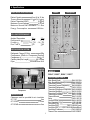
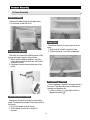
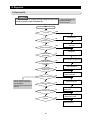
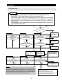
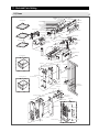
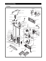
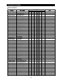
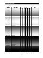
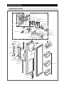
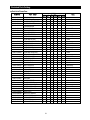
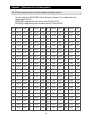
1
SAMSUNG Home Appliance Service
For the latest parts information,
Please access to our service web site
(http://www.e4buyer.com/refrigerator)
SIDE-BY-SIDE REFRIGERATOR
Model:
RS 24***
RS 25***
RS 26***
RS 27***
WARNING
IMPORTANT SAFETY NOTICE
The service guide is for service men with adequate backgrounds of
electrical, electronic, and mechanical experience. Any attempt to repair
a major appliance may result in personal injury and property damage.
The manufacturer or dealer cannot be responsible for the interpretation
of this information.
All rights reserved. This service guide may not be reproduced in whole or in
part in any form without written permission from the SAMSUNG ELECTRONICS
Company.
2
Contents
1. Introduction
4
2. Installation
5
3. Nomenclature
6
4. Specifications
7
5. Interior Views and Dimensions
8
6. Refrigeration Cycle and Cool Air Circulation Route
10
7. Mechanical Disassembly
12
8. Operation Function
22
9. Circuit Descriptions
37
10. Diagnostics
46
11. Illustrated Parts Catalog
58
12. Safety instruction on services
74
Appendix Ⅰ (Reference for circuit diagnostics)
75
Appendix Ⅱ (Circuit diagram)
80
3
1. INTRODUCTION
A newly developed SAMSUNG side by side refrigerator in 2002 has the following
characteristics.
1) Twin Cooling System
The refrigerator and the freezer have two
evaporators. Given this independent system, the
freezer and the refrigerator are cooled individually as
required and are, therefore, more efficient. Food
odor from the refrigerator does not affect food in the
freezer due to separate air flow circulation.
2) Multi-Flow System
Cool air circulates through multiple vents on every
shelf level. This provides even distribution of cooling
inside cabinets to keep your food fresh longer.
3) Xtra SpaceTM
Vertical room next to the ice maker in the freezer
provides space for pizza etc.
4) Door Alarm
Beep sound reminds you the door is open.
5) Xtra FreshTM
Optimized humidity control keeps vegetables & fruits
fresh.
6) Deodorizer
Reusable deodorizer keeps the refrigerator air
fresh and odor free.
7) CoolSelect ZoneTM Drawer (Optional)
User can select Quick Cool, and Select for quickly
soft freeze, chill, and cool. Select Soft freeze,Chill or
Cool to control the temperature of the drawer.
4
2. INSTALLATION
1) To protect refrigerator in movement
Use padded hand truck as shown. If entrance width is
less than 1m, remove doors prior to installation and
reattach doors according to procedure below.
2) Remove all protective tape and pad in refrigerators.
Connect water lines and power cord. Adjust the
clearance between the doors.
3) Set the temperature control to the temperature and
wait for an hour.
The refrigerator should get slightly chilled and the motor
runs smoothly.
4) Once the refrigerator temperature is sufficiently low
You can store food in the refrigerator. After starting the
refrigerator, it takes a few hours to reach the appropriate
temperature.
Removing Doors
Attaching Doors
Open the freezer and refrigerator doors, and
then take off the front leg cover assembly by
turning the three screws counter-clockwise.
Remove the screw from clamp disconnect, the
water tube by pressing the coupler, and pulling
the water tube away.
Insert the lower hinge in the bracket lower
hinge. Attach the freezer door by inserting the
hose in the lower side of the door into the hole in
the lower hinge and pulling the hose down.
Insert the upper hinge shaft into the hole. After
leveling between the upper hinge hole and the
hole of the cabinet. Reattach hinge screws and
screw in the clockwise direction. Connect the
wires. Put the front part of the upper hinge cover
on the front part of the upper hinge and reattach
from the front part of the upper hinge cover first.
With the door closed, remove the upper hinge
cover using a screwdriver, and then disconnect
the wires. Remove hinge screws and ground
screw counter-clockwise, and take off the upper
hinge. Take care removing the door to ensure that
it does not fall on you.
Remove the door from the lower hinge by
carefully lifting the door so as not to damage the
water tube. Remove the lower hinge from the
lower hinge bracket by lifting the lower hinge.
5
3. Nomenclature
BUSINESS MODEL BAR CODE
MANUFACTURE SPEC.
MANUFACTURE MODEL
R S 25 F A SW 1
/ XET (E Q G FA I)
BUYER NO.
CONTROL METHOD : E-ELECTRONIC
S- SEMI ELECTRONIC
POWER
K - 220V/50Hz
C - 115V/60Hz P - 127V/60Hz
H - 220V/50,60Hz Q - 230 240V/50Hz
DOOR PLATE
G - EMBOSSED + SECC
H - V/STEEL + SECC
P - PET + SECC
R - REAL STAINLESS
X- TRIM KIT
DOOR PLATE COLOR
NORMAL ; SW - SNOW WHITE
DB - DAISY BEIGE
TRIM KIT ;
SG - SILVER GLASS
MR - MIRROR
AL - ALUMINUM
NC - NATURAL CHERRY
OPTION
F* : FULL OPTION
D* : DISPENSER
M* : HOME BAR
N* : BASIC
FILTER/KEY
I : INTERIOR FILTER
O : EXTERIOR FILTER
Y : KEY
N : KEY
SL - NOBLE STAINLESS
LB - ILLUMANATE BLUE
TR - TROPICAL RED
NK - NATURE KHAKI
DW - DARK WALNUT
HANDLE TYPE (DESIGN)
A : A-TOP HANDLE
C : SKI BAR TYPE
G : LONG BAR
L : LONG BAR- TRIM KIT E : K-TOP HANDLE(only for N-PRJ)
GATEGORY
S : SBS
H : NETWORKING
Function ; N : BASIC MODEL
B : HOME BAR MODEL
D : DISPENSER
F : FULL
TM
J : DISPENSER+CoolSelect Zone K : FULL + CoolSelect ZoneTM
NET CAPA : 24, 25,26, 27(cu.ft)
Product : R - SAMSUNG REFRIGERATOR B-OEM REFRIGERATOR
6
4. Specifications
ELECTRICAL SPECIFICATIONS
Freezer
Refrigerator
Defrost Control
From 24 to 32 hrs
Thermo-Bimetal
12 (off)/-5 (on)
Defrost Thermistor(502AT)
12 (off)
Maximum Current Leakage
0.25 mA
Maximum Ground Path Resistance 0.1 Ohm
Energy Consumption
KWH/mo.
NO LOAD PERFORMANCE
Ambient Temperature
Refrigerator,
Freezer,
Run Time,%
20
1 7
-14 -25
40
32
1 7
-14 -25
60
Fan
Fan
REFRIGERATION SYSTEM
(Air inlet)
Heat exchanger
Refrigerant Charge (R134a)
220g
Compressor (Refer to Component Partlist)
Compressor oil
Freol -15
0.85, 3300mm
Capillary tube(Dia, Length)
Dryer
Molecular Sieve XH-9
C-Fan
(Air inlet)
Electric box
MODELS
RS24**, RS25**, RS26**, RS27**
REPLACEMENT PARTS
Dryer
Compressor
Main Board(Good)
DA41-00139A
Main Board(Better&Best)
DA41-00107A
Thermistor(Freezer)
DA32-10109W
Thermistor(Freezer Evaporator) DA32-00006A
Thermistor(Refrigerator)
DA32-10105U
Thermistor(Refrigerator Evaporator) DA32-00006B
Thermistor(Ambient)
DA32-10109V
Thermistor(CoolSelect ZoneTM)
DA32-10109X
Thermistor(Ice-Maker)
DA32-10108B
Thermo-Bimetal
DA47-10160E
Relay
DA35-10013Q
Overload Relay
DA34-10003D
Run Capacitor (12 )
2501-001045
Fan-Motor(FRE)
DA31-00020E
Fan-Motor(REF)
DA31-00002S(Good)
Fan-Motor(REF)
DA31-00020E(Better&Best)
Fan-Motor(Condenser)
DA31-00020H
Thermal Fuse
DA47-00095C
Sub-condenser
INSTALLATION
Clearance must be provided for air circulation
AT TOP
5cm
AT SIDES
0.25cm
AT REAR
5cm
7
5. Interior Views and Dimensions
5-1) Shelves and Bins
Freezer
Light
Xtra SpaceTM
Door Bin
Light
Ice Chute
Light Switch
Ice Maker
Glass Shelf
Pockets
Plastic Drawers
Front Leg Cover
RS 24/25/26/27
with Basic or Beverage StationTM
RS 24/25/26/27
with Dispenser or Beverage StationTM
Refrigerator
Water Filter (optional)
Light (upper)
Dairy Compartment
Wine Rack(optional)
Spill-proof glass Shelf
Muti-purpose Bin
Light Switch
Foldable Shelf (optional)
Beverage Station (optional)
Lights (lower)(optional)
Twin Deodorizer(optional)
Egg Container
CoolSelect ZoneTM
Drawer (Chilled Bin for optional)
Door Bin Top Lips
Vegetable & Fruit
Drawer (upper)
Gallon Door Bins
8
Interior Views and Dimensions
5-2) Dimensions of Refrigerator(RS24/25/26/27)
B
H
G
385.5
F
E
908
511.5
A
C
60
1773
Beverage StationTM
(option)
54
1637
29
D
A
B
C
D
E
F
G
H
RS24
710
50
864
774
1130.5
1255.5
420.5
545.5
RS25
710
85
899
809
1138
1263
428
553.0
RS26
760
50
914
824
1180.5
1305.3
420.5
545.3
RS27
760
85
949
859
1188
1313
4280
553.0
9
6. Refrigeration Cycle and Cool Air Circulation Route
6-1) Refrigerant Route in Refrigeration cycle
Compressor Sub-condenser Side Cluster Pipe(FRE) Side Cluster Pipe(REF) Hot Pipe
Dryer Capillary Tube Refrigerator Evaporator Freezer Evaporator Suction Pipe Compressor
Refrigerator Evaporator
SIDE CLUSTER PIPE
ACCUMULATOR
Freezer Evaporator
Dryer
SUCTION PIPE
SUB-CONDENSER
Capillary Tube
Muffler
Compressor
Hot Pipe
10
Hot Pipe
Refrigeration Cycle and Cool Air Circulation Route
6-2) Cool Air Circulation
Refrigerator
Freezer
11
7. Mechanical Disassembly
7-1) Refrigerator Disassembly
Control Panel
Door Handle
Beverage StationTM
Door Gasket
Refrigerator Door Light Switch
Refrigerator Light
Tempered Glass Shelf
Plastic Drawers in Refrigerator
Gallon Door Bin
Water Filter
Evaporator Cover in the Refrigerator
Upper Ductwork
Evaporator Fan Motor
Evaporator in Refrigerator
Refrigerator Thermistor
CoolSelect ZoneTM Thermistor
14
14
14
14
15
15
15
15
15
16
16
16
16
17
17
17
7-2) Freezer Disassembly
Door Bin in Freezer
Freezer Door Light Switch
Plastic(Wire) Drawer in Freezer
Freezer Shelf
Ice Dispenser Ice Maker
Auger Motor Case
Freezer Light
Evaporator Cover in Freezer
Upper Ductwork
Evaporator Fan Motor
Evaporator in Freezer
Freezer Thermistor
Ambient Thermistor
Ice-Maker Thermistor
18
18
18
18
18
19
20
20
20
20
21
21
21
21
7-3) Machine Compartment Disassembly
Machine Compartment
Water Solenoids
Condenser Fan
Sub-condenser
Electrix Box
22
22
22
22
12
7. Mechanical Disassembly
7-1) Refrigerator Disassembly
Control Panel
Beverage StationTM
1. Insert a flat-blade screwdriver on the slot as shown,
and unlock the tabs.
2. Disconnect the wire connector in the back of control
panel.
The beverage stationTM allows access to the
refrigerator without opening the refrigerator door.
1. Open the door beverage stationTM
2. With a small flat-blade screwdriver,take out the
rubbercap, then put it into the small hole and
push the button inside.
3. Take off its door.
Door Handle
The door handles allow access into the refrigerator
and freezer. They are front mounted with Phillips
head screws.
1. With a small flat-blade screwdriver, press the
small button and pull handle cover out.
2. Remove the Phillips screws (8).
3. Lift the handle with an in and upward motion until
it disengages the locking tabs. Pull the handle
outward to remove it.
Door Gasket
The door gasket is a molded gasket set into a
channel located in the door liner.
1. Open the door.
2. Grasp the gasket and pull in an outward motion
until the molded gasket separates from the door
liner.
Button
13
Mechanical Disassembly
Refrigerator Door Light Switch
The refrigerator has a door light switch located in
the upper right corner for the refrigerator.
1. Use a small flat-blade screwdriver to unlock the
locking tab and pull the switch out until the
wire connector is visible.
Plastic Drawers in Refrigerator
Drawers are designed for storage of fruits,
vegetables, and deli items. The drawers are located
in the lower portion of the refrigerator.
1. Pull out the drawer as far as it goes.
2. Tilt the drawer up and pull it out until it is
removed.
Refrigerator Light
The refrigerator lights are located in the upper and
lower portion of refrigerator.
1. Pull out the screw cap and remove the screw.
2. To access the lower lights, pull out the screw cap
and remove the screw.
3. Remove the lamp cover by unlocking the tabs
and pulling the cover down.
Gallon Door Bin
The door bins allow storage of perishable items.
1. Push the bin up and slide it out.
Tempered Glass Shelf
These shelves allow the storage of larger items and
pull out for easy access.
1. Pull the shelf out as for as it goes.
2. Lift it up and remove it.
14
Mechanical Disassembly
Water Filter
The water filter is located in the upper right-hand
corner of the refrigerator. The water filter filters water
for the ice maker and the water dispenser.
1. Turn the water filter 1/2 turn counterclockwise and
pull it down.
2. To install the filter, align the indication mark
(unlock position) and push it up while turning 1/2
turn clockwise until the lock position is aligned.
Do not over tighten.
Upper Ductwork
1. Remove the screw caps (2) and screws (5).
2. Slide the upper fan ductwork out while
disconnecting the wire connector(lamp and
thermistor).
Evaporator Cover in the Refrigerator
1. Pull out the screw cap and remove the screw.
2. Remove the lamp cover by unlocking the tabs
and pulling the cover down.
3. Remove the water tank from the evaporator cover
by unscrewing the screws (2).
4. Remove the screws (6) at the evaporator cover
and the two fixed screws of the wire connector
cover.
5. Take off motor and lamp wire connector located
on the upper liner.
6. Remove the duckwork of the evaporator fan in the
direction of the arrow as shown.
Evaporator Fan Motor
The evaporator fan is located in the middle rear of
the freezer. This fan circulates cold air in the freezer.
1. Remove screws (4) located at the four corners of
the fan bracket.
2. Take the fan motor assembly off.
15
Mechanical Disassembly
Evaporator in Refrigerator
Refrigerator Thermistor
Evaporator is located in the bottom of refrigerator.
1. Take off the ductwork in refrigerator.
2. Disconnect the wire connector.(Heater and
Thermistor)
3. Desolder the capillary tube and the suction line
from the evaporator.
4. Remove the evaporator.
5. With a file, score the capillary tube just upstream
of the soldered point. Break off the soldered
section to help prevent solder from plugging the
tube during soldering.
6. Place a new evaporator and braze the suction
and capillary tube to evaporator using silver
solder.
7. Install a replacement dryer.
8. Evacuate and recharge the system using
reasonable procedures.
The refrigerator thermistor is located inside of the
upper light cover of the refrigerator.
Thermistor
CoolSelect ZoneTM Thermistor
Thermistor
The CoolSelect ZoneTM thermistor is located outside
the back of CoolSelect ZoneTM drawer. The
temperature signal sends the micro-processor.
Capillary Tube
Suction Line
CoolSelect ZoneTM Thermistor
Thermal Fuse
16
Mechanical Disassembly
7-2) Freezer Disassembly
Door Bin in Freezer
The door bins allow storage of perishable items.
1. Push the bin up and slide it out.
Freezer Shelf
The shelves slide out for easy access for frozen
items.
1. Slide the shelf out until it reaches its stop.
2. Tilt down and slide it out of the compartment.
Freezer Door Light Switch
This switch is located in the left-hand portion of the
freezer and sends a signal to the processor.
1. With a small flat-blade screwdriver, unlock the
locking tabs and pull the switch out until the wire
connector is visible.
2. Disconnect the wire connector and remove the
switch.
Ice Dispenser
Ice Maker
The ice dispenser is located in the upper portion of
the freezer. This assembly stores ice made by the
icemaker and dispenses ice.
1. Lift the ice bucket up and slide out the ice
dispenser assembly .
Plastic (Wire) Drawer in Freezer
Drawers are designed for storage of meat and dry
foods. The drawers are located in the lower portion of
the freezer.
1. Pull out the drawer as far as it goes.
2. Tilt the drawer up and pull it out until it is
removed.
17
Mechanical Disassembly
top of the liner, and slide the ice maker in.
5. Tighten the screws (2) of the ice maker support.
Auger Motor Case
This shelf is designed to support the ice maker &
ice dispensed and Xtra SpaceTM.
1. Remove the Xtra SpaceTM cover to push it down
near the partition.
2. Slide the partition out.
3. Remove the screws (2) on the bottom front of the
case.
4. Slide out the case while disconnecting the wire
connect.
The ice maker is located inside of the ice dispenser
assembly.
1. Remove ice maker support screws (2), and slide out.
2. Disconnect the ice maker wire connector.
3. Unlock the locking tabs to separate the ice maker kit.
Partition
In order to assemble the icemaker kit.
1. Assemble the geared motor shaft and the front of
ice tray.
2. Lift the front locking tab and assemble the ice
maker kit.
3. Connect the ice maker wire connector.
4. Match the tab holes and tabs(2) located on the
Screws
18
Mechanical Disassembly
Freezer Light
Upper Ductwork
1. Remove the screw cap and screw.
2. Slide the upper fan ductwork out while
disconnecting the wire connector (Lamp and
Thermistor).
The freezer light is located in the bottom of the
auger motor case. The light is covered by an opaque
cover.
1. Remove the screw and the light cover.
Evaporator Cover in Freezer
1. Pull out the screw caps and remove screws (6).
2. Remove the ductwork of the evaporator fan in the
direction of the arrow as shown.
3. Disconnect the wire connector.
Evaporator Fan Motor
The evaporator fan is located in the lower rear of
refrigerator. This fan circulates cold air in the
refrigerator.
1. Remove screw(4) located at the four corners of
the fan bracket.
2. Take the fan motor assembly off.
19
Mechanical Disassembly
Evaporator in Freezer
Evaporator is located in the bottom of freezer to
produce cold air driven across the evaporator coils.
1. Take off the ductwork in Freezer.
2. Disconnect the wire connector (Heater, Bimental,
and Thermistor).
3. Desolder the inlet and outlet tubes.
4. Remove the evaporator.
5. Take the same steps to seal the system as
mentioned earlier.
Freezer Thermistor
Ambient Thermistor
The ambient thermistor is located inside the upper
hinge cover. It sends temperature signals to the
micro-processor.
Accumulator
Bimetal
Ambient
Thermistor
Thermal
Fuse
Ice-MakerThermistor
The Ice-Maker thermistor is located in its bottom.
The temperature signal sends the micro-processor.
Thermistor
Freezer Thermistor
The freezer thermistor is located at the top left of
freezer vent. It sends temperature signals to the
micro-processor.
Thermistor(Ice-Maker)
20
Mechanical Disassembly
7-3) Machine Compartment Disassembly
3. Disconnect water tubes (3).
Machine Compartment & Electric Box
1. Disconnect the power cord of the refrigerator.
2. Remove the fixed screws (6) of compressor
cover.
Condenser Fan
3. Slide up and take off the compressor cover to
see the machine compartment.
The condenser Fan is located in the middle of
machine compartment. It cools down the subcondenser and the compressor.
1. Disconnect the condenser fan wire.
2. Remove screw (1) on the drain water tray.
3. Take the condenser fan assembly off.
4. Press the tab in electric box cover to take out
by using a flat-blade screw driver.
(+)driver
Sub-condenser
The sub-condenser is located in the machine
compartment. The heat is extracted by condenser
fan.
1. Desolder the compressor discharge &
the sub-condenser outlet.
2. Take out the sub-condenser.
(-)driver
PCB-MAIN ASSY
Water Solenoids
When the solenoids receive a signal from the microprocessor, they supply water to the water dispenser
or the ice maker.
1. Remove bracket screw (1) on electric box.
2. Take the solenoids assembly out.
Desoldering Point
21
8. Operation Function
8-1) Digital Panel
23
8-2) Temperature Control Function
24
8-3) Power Freeze and Power Cool Functions
25
8-4) Child Lock Function
25
8-5) Ice
Water Dispenser Function
26
8-6) C-Fan Motor Delay Function of the Machine Compartment
26
8-7) CoolSelect ZoneTM Function(optional)
26
8-8) Water Filter Indicator Function
27
8-9) Ice-Maker Function
27
8-10) Defrost Function
29
8-11) Forced Operation Function (Pull-down/R-Defrost/R,F-Defrost/Cancellation)
30
8-12) Sound Function
31
8-13) Exhibition Function
31
8-14) Self-Diagnostics Function
31
8-15) Load Operation Check Function
33
8-16) Restoration Function for Power Outage
33
8-17) Set Point Shift Function
33
8-18) Table of Set Point Shift Function
34
22
8. Operation Function
8-1) Control Panel
●
For general control panel (Full option & Basic Model)
23
8. Operation Function
●
The control panel is applied only for Europe Area
Note) Initially the light of moisture control button is on. If the moisture in the dispenser or Beverage StationTM is
found, press this button. So the light will be on, and eliminate the moisture.
8-2) Temperature Control Function
When the system power is initally engaged, the default set temperature are -20 for the freezer and 3 for the set
refrigerator, respectively. The numbers shown on the digital display panel stand for the actual compartments
temperatures. When the compartment temperatures go down, so do the numbers on the display panel, and finally they
reach the set temperatures. Once the system is stabilized, the display temperatures are the set temperature.
1) Freezer Temperature Control.
To select a set temperature, press the Freezer Temp. button. The display shows the set temperature from -14 to
-25 in sequence.
2) Refrigerator Temperature Control.
To select a set temperature, press the Fridge Temp. button. The display shown the set temperature from 1 to
7 in sequence.
note) Because of the temperature sensor sensivity, the refrigerator can be under and/or over cooled when
the air flow is blocked by stored foods. (Temperature range of the sensor : -9 ∼30 )
In the event of a power failure, if the freezer temperature is maintained lower than 5 , the last
selected set temperature and functions memorized in EEPROM will be restored when the power is on.
24
Operation Function
8-3) Power Freeze and Power Cool Functions
Select the Power Freeze or Power Cool buttons separately.
These buttons are toggled ON and OFF and the indicators as well.
Although you select Power Freeze or Power Cool, the set temperatures in the freezer and refrigerator are not
changed.
● The set temperatures for the compartments can be changed while these functions are in use.
●
●
●
1) Power Freeze function
1-1) When you press the Power Freeze button, the LED indicator lights right away, but there is 10 seconds lag time
to an actual operation. When this button is pressed again, the Power Freeze function stops and the indicator is off
immediately .
1-2) If you select Power Freeze, both the compressor and the freezer fan run for 10 hours continuously.
note) When the Power Freeze is selected, it enables maximum ice maker output. The ice making interval is
reduced from 90 mins to 55 mins (55 mins after the water delivery, if the ice temperature is maintained
lower than -7 , the ice tray will be twisted). When the ice bucket is full before 10 hours of operation,
Power Freeze is automatically terminated.
1-3) During Power Freeze, the freezer retains the current settings.
1-4) When Power Freeze expires, the indicator goes off and the freezer set temperature will be restored.
2) Power Cool function
2-1) Power Cool operation and the indicator work exactly same as the Power Freeze function.
2-2) When Power Cool is selected, COMP and R-FAN operate continuosly until the refrigerator reaches -4 . This
function will be terminated after 2 ½ hr running.
3) When you select Power Freeze and Power Cool together
Each function works at the same time. The COMP and F-FAN run continuously and the R-FAN runs until -4
in the refrigerator.
4) Initial Power-On
4-1) The freezer and the refrigerator temperatures are higher than -10 and 10 espectively if, respectively. If Power
Freeze is selected, the R-FAN will be off. If Power Cool is selected, the F-FAN will be off.
4-2) When both functions are selected, there is no benefit of fast cooling for each compartment.
8-4) Child Lock Function
●
When the child lock button is pressed for 3 seconds, the child lock indicator is on with an audible tone.
-When it is locked, no function commands except the Ice type button will be accepted.
-This function will prevent accidental setting that may be caused by children or pets.
-To unlock the setting functions, press this button for 3 seconds again.
25
Operation Function
8-5) Ice & Water Dispenser Function
●
Among several ice-maker functions, the ice extraction function is performed by mechanical system. Only the relay
control for a cubed-ice dispensing and the SSR control for the ice chute door are performed electronically.
1) Select Cubed/Crushed/Ice-off function
1-1) The Ice Type button selects Cubed/Crushed/Ice-off options in sequence.
1-2) A default setting is Cubed option.
1-3) If Cubed ice is selected, the Crushed ice bypass solenoid and the geared motor will allow Cubed ice to by pass
the ice Crusher.
1-4) If Ice-off is selected, the ice maker will stop working. This option will be terminated when Cubed and Crushed
options are selected.
Note) When the Ice-off indicator is on and the remained ice is in tray, only Cubed ice will be dispensed from
the ice bucket.
1-5) The ice chute door must be open for 5 seconds after dispensing ceases. After this 5 seconds delay, SSR will be
controlled to shut the ice chute door.
Note) Do not force to close the ice chute door. Try to dispense some more ice again to work it automatically.
2) Water Dispenser function
2-1) To dispense water, depress the water dispenser lever located in the dispenser recess.
2-2) When the lever is depressed, the water solenoid valve located in the machine compartment is open to flow water.
2-3) There is no electronic control function for this option.
8-6) C-Fan Motor Delay Function of the Machine Compartment
●
According to the ambient temperature, the condenser fan located in the machine compartment is operated with
different modes.
C-FAN
Delay function
Operation
Ranges of ambient temp.
Above 19
C-FAN is ON as soon as the compressor is on.
16 ~ 18
C-FAN is ON with 5 minutes delay from the compressor on.
Below 15
C-FAN is OFF regardless of the compressor operation.
8-7) CoolSelect ZoneTM Function (Optional)
To select this function, open the refrigerator door and press the button on the control panel of CoolSelect Zone TM
drawer.
● When the CoolSelect ZoneTM function is selected, the damper inside fan ductwork is open. So the refrigerator cooling
is performed first, then the damper is closed to control the CoolSelect ZoneTM temperature.
●
26
Operation Function
1) Select function
1-1) Using Select button, Cool, Chill(-1 ), and Soft Freeze(-5 ) options can be selected in sequence. Cool option
maintains a set temperature of the refrigerator.
2) Quick Cool function
2-1) If the Quick Cool is selected, LEDs will flash 60 and Min. The count will be decreased in every minute.
2-2) To cancel this function, press Quick Cool button again or Thaw button or Select button. Otherwise, it will be
terminated 60 minutes later automatically.
2-3) After this function ends, this drawer will come back to Cool option.
2-4) A defrost cycle will be postponed until Quick Cool option is finished.
3) Thaw function
3-1)When the thaw button is pressed, LEDs will flash 4, 6, 10, and 12 in sequence and Hr.
3-2) The count will be decreased in every hour.
3-3) A cancellation of this function is same as Quick Cool function.
3-4) After this function ends, this drawer will be maintained with -1 .
3-5) While the compressor is on, this drawer retains a certain temperature and while the compressor is off, the defrost
heater is activated and R-FAN is on with a closed position of the damper.
8-8) Water Filter Indicator Function
1) Filter Indicator
1-1)This indicator initally lights in green. The light color will be changed to orange after 5 month operation then to red
at the 6th month. The EEPROM in the control board counts a period of time regardless of a power failure.
1-2)To reset the counter and the light color, press Ice Type button and Child lock button for 3 seconds simultaneously.
1-3)If these two buttons are pressed simultaneously for 5 seconds, this function will cease.
1-4)To restore this function, press these buttons again for 3 seconds.
8-9) Ice-Maker Function
●
The Ice-maker is referred to the device with an automatic ice production, storage in the ice bucket and dispensing
through the ice chute.
1) Ice-maker parts
ICE-WAKER, KIT
EJECT-MOTOR
SUPT-RUBBER
EJECT-SENSOR
LEVELING-SWITCH
ICE Full-SWITCH
TEST-SWITCH
TRAY-ICE
SCREW
FIXER-SENSOR
KNOB-TOUCH
GUIDE-ICE(Lever to check ice full)
27
COVER-SENSOR
Operation Function
2) Preparation of Ice-maker
2-1) Connect the water line to the water supply valve of refrigerator to supply water. (See how to connect a water
supply line in the owner’s manual.)
2-2) Push the bucket back fully so that the guide-ice of ice maker should not touch the back of bucket. (If the back of
bucket touches the guide-ice of ice maker, the ice maker will not make ice any more because of a ice full signal.)
2-3) It takes 6 hours to have a first ice, and throw away 2-3 times of these ice to make sure the supplied water clean.
Push the bucket back fully so that the
lever should not be pushed up.
1) Initial Operation function
1-1) Whenever the power is on, the control board checks the ice tray leveling with the leveling switch within 2 seconds.
1-2) If the leveling switch is not off position, the geared motor will turn to the initial position to make the ice tray leveled.
1-3) When the ice tray is leveled, it will remain this position for 2 hours (1 cycle time for ice production).
1-4) After 2 hours, the sensor located under the ice tray will measure the tray temperature. If the temperature is
maintained lower than -7 for 5 minutes, and the ice full switch is off position, the ice tray twisting process will
begin.
<Reference table>
Leveling S/W
ON(“LOW”)
ON(“LOW”)
OFF(“HIGH”)
Ice full S/W
ON(“LOW”)
OFF(“HIGH”)
ON(“LOW”)
Judgement
Not ready
Not ready
Not ready(Ice bucket with full of ice )
OFF(“HIGH”)
OFF(“HIGH”)
Ready
28
Remark
MICOM Port
PIN #51: Leveling
PIN #51: Ice full
Port level
OFF : 4.5V ↑
ON : 0.5V ↓
Operation Function
2) Water Supply function
2-1) When the ice tray is leveled again after ejecting ice, the water solenoid value will be controlled to supply water by
time check basis. (See the “Time to supply water” Table)
3) Ice production
3-1) After 90 minutes pass from the water supply, the control board will check the temperature.
3-2) If the sensor reads the temperature lower than -9 for more than 5 minutes, than the ice production process is
completed.
4) Test function
● In order to operate a test function, press the knob (Test Switch) for 1.5 second.
● This function can be used to check a proper working, to clean the ice tray, and to adjust the water level in the ice tray.
4-1) This function only works when the ice tray is leveled and the ice full signal is cleared.
4-2) When the water line is connected, each process such as a water supply, ejection, and leveling, can be investigated
by this button.
5) Ice off function
5-1) When the Ice off option is selected by Ice Type button, the ice making process will cease.
5-2) When the ice making process ceases, the final state will be the ice tray with the supplied water.
5-3) When Cubed or Crushed option is selected again, the control board will check an accummlated time period. After
making it 90 minutes and when the ice tray temperature is acceptable, ice ejection process will begin.
6) Functions when the freezer door is open
● When the freeze door is open, all ice maker related processes will cease in order to minimize noise and to prevent ice
from dispensing.
6-1) The ice tray stops moving regardless of the position.
6-2) The water supply process remains working as usual.
6-3) If the ice tray is in the middle of ice ejecting process, close the freezer for 30 seconds and check if the tray is
leveled. If it is not leveled, it must be out of order.
8-10) Defrost Function
1) A defrost is determined based on the accumulated compressor on-time.
2) When the power is engaged for the first time, the defrost cycle for the freezer and the refrigerator will begin after 4
hours of the accumulated compressor on-time.
3) A defrost interval depends on the ambient temperature, the number of door openings, and the door open time.
4) A minimum interval is 6 hours and a maximum is 8 hours for the refrigerator, and 12 hours and 16 hours for the
freezer, respectively.
5) The defrost heater on-time is determined by the defrost sensors as follow :
Refrigerator
Heater ON
Below 10
Heater OFF
17
29
Freezer
-
10
Operation Function
8-11) Forced Operation Function (Pull-down / R-Defrost / R.F-Defrost / Cancellation)
This function enables a pull-down mode, a defrost mode for the refrigerator only, a defrost mode for the freezer and
the refrigerator at the same time, and a cancellation of this function.
● Press Power Freeze and Fridge Temp. buttons for 8 seconds simultameously to get in the ready mode for a forced
operation.
● The display panel will return to normal after 20 seconds in the ready mode.
● At the ready mode, press any button(except Ice Type and Child Lock) once to start a pull-down operation, twice for a
defrost cycle for the refrigerator, three times for a defrost cycle for the freezer and the refrigerator, and finally four times
for cancellation of this function.
● Another way to cancel this function is to simply plug out and in the power cord.
●
1) Pull-down Operation
1-1) At the ready mode, press any button once then the buzzer will beep (ON for 1/2 second and OFF for 1/2 second)
until this mode is cancelled.
1-2) At this pull-down mode, the compressor will start immediately (No 5 minute delay) and if the system is in the
defrost cycle, it will be cancelled right away.
Note) If this pull-down mode begins right after the compressor was off, the compressor may not start to run due to an
overload condition.
1-3) At this mode, the compressor and freezer fan will operate continuously for 24 hours and the refrigerator fan will be
on and off according to the set temperature(-20 )
1-4) After 24 hour operation, the system will be cycled at -25 for the freezer and 1 for the refrigerator.
1-5) In order to cancel this mode at any time, select the next mode on the ready mode or power off the system.
2) Defrost operation
2-1) At the pull-down mode, press any button again on the ready mode to begin the defrost cycle for the refrigerator.
2-2) The beep sound continues for 3 second at the beginning, then ON for 3/4 seconds and OFF for 1/4 second until
this mode cease.
2-3) After this operation, the system will come back to normal operation.
2-4) At this mode, press any button again on the ready mode to operate the defrost cycles for both compartments.
2-5) The beep sound continues for 3 seconds at that time, then ON for 1/4 second and OFF for 3/4 seconds until the
defrost operation cease.
3) Cancellation
3-1) At the R,F-Defrost mode, press ant button again on the ready mode to return to a normal operation.
3-2) Simply unplug the power cord, then plug it again to return to a normal operation.
30
Operation Function
8-12) Sound Function
1) Sound function
1-1) To make sure a command input, whenever a button is pressed, a “ding-dong” sounds.
1-2) When two or more buttons are pressed simultaneously or if a wrong button is pressed, there is no sound.
2) Door Open Alarm
2-1) When the doors remain open for 2 minutes, there are 10 times beeps.
2-2) If the doors continue to remain open more than 2 minutes, the additional 10 beeps interval will change to 1 minute.
2-3) The beeps will cease immediately when the doors are closed.
8-13) Exhibition Function
●
This function is for a display purpose on the floor of show room or store.
1) Mode ON/OFF
1-1) For the exhibition mode, press Power Freeze and Freezer Temp. buttons simultaneously for 8 seconds until a
“ding-dong” sounds.
1-2) Press the same time buttons again for 8 seconds to cancel this mode put with a “ding-dong” sound.
2) Operation
2-1) Most of the system function except the compressor operation are working properly.
2-2) There is no defrost cycle in this mode.
8-14) Self-Diagnostics Function
1) Self-Diagnostics in the initial Power ON
1-1)The control board performs a self diagnostics test within 1 second and check out the temperature sensors abilities.
1-2) If a sensor failure occurs, a corresponding LED segment will blink with a beep.
1-3) When a LED segment blinks, only the cancellation function (Press Power Freeze and Power Cool buttons
simultaneously for 8 seconds) is acceptable.
1-4) After a replacement of bad sensor or a cancellation of this function, this self diagnostics will end.
2) Self-Diagnostics in the normal operation
2-1) To select this function, press Power Freeze and Power Cool buttons simultaneously for 8 seconds with an audible
tone.
2-2) In the self diagnostic mode, only corresponding LED segments will be illuminated (see the check list on the next
page)
2-3) After a 30 second illumination of error signal, the system will return to the normal operation.
31
Operation Function
Self-diagnostics check list
NO
①
②
③
④
⑤
⑥
⑦
⑧
⑨
⑩
⑪
Error
I/M-SENSOR
R-SENSOR
R-DEF-SENSOR
R-FAN ERROR
I/M function error
CoolSelect ZoneTM SENSOR
EXIT-SENSOR
F-SENSOR
F-DEF ERROR
F-FAN ERROR
C-FAN ERROR
If any LEDs blink, the corresponding sensors and
components must be checked for an error.
Error items of self-diagnostics
NO
Error items
LED Display
Details
Remarks
01 I/M-SENSOR
Indicate Error when the temperature sensed
I/M sensor connector missing; contact
failure, electric wire cut, short-circuit; I/M- by I/M-sensor is higher than 65℃ or lower
sensor failure; and so on
than -50℃.
02 R-SENSOR
REF sensor connector missing; contact
failure, electric wire cut, short- circuit; Rsensor itself failure; and so on
DEFROST
03 REFSENSOR
REF evaporator internal defrosting sensor Indicate Error when the temperature sensed by R
connector missing; contact failure, electric defrosting sensor is higher than 65℃ or lower
wire cut, short-circuit; sensor itself failure;
than -50℃.
and so on
04 R-FAN ERROR
R-Fan motor operation failure; feedback
Indicate Error if the F and G signals generated by the
signal line contact failed, electric wire cut,
FAN-motor operation are not input.
short- circuit; and so on
Indicate Error when the temperature sensed
by R-sensor is higher than 65℃ or lower than
-50℃.
05
I/M function
ERROR
Ice-ejector and level failed three times
or more
06
CoolSelect
ZoneTM sensor
CoolSelect ZoneTM sensor connector
missing; contact failed, electric wire cut,
short-circuit; CoolSelect ZoneTM sensor itself
failed; and so on.
Indicate Error when the temperature sensed by
CoolSelect ZoneTM sensor is higher than 65℃ or
lower than -50℃.
07 Ambient Air
Air sensor connector missing; contact
failure, electric wire cut, short-circuit;
open air sensor itself failure; and so on
Indicate Error when the temperature sensed by
the open air sensor is higher than 65℃ or lower
than -50℃.
08 F-SENSOR
FRE sensor connector missing; contact Indicate Error when the temperature sensed
failed, electric wire cut, short-circuit; F- by F-sensor is higher than 65℃ or lower than
Room sensor itself failure.
-50℃.
Defrost
09 FRE
SENSOR
FRE evaporator defrosting sensor
connector missing; contact failed,
electric wire cut, short-circuit; sensor
itself failure; and so on
Indicate Error when the temperature sensed by
F-defrosting sensor is higher than 65℃ or
lower than -50℃.
10 F-FAN ERROR
F-Fan motor operation failure; feedback
signal line contact failure, motor’s electric
wire missing; and so on.
Indicate Error if the F and G signals generated by
the FAN-motor operation are not input.
11 C-FAN ERROR
C-Fan motor operation failure; feedback
signal line contact failure, motor’s electric
wire missing; and so on.
Indicate Error if the F and G signals generated by the
FAN-motor operation are not input
SENSOR
(COMP-FAN)
32
Operation Function
8-15) Load Operation Check Function
1) In the normal operation, press Power Freeze and Power Cool buttons simultaneously for 6 second, then the display
panel will blink for 2 seconds.
2) Press Fridge Temp. button ⓐ to get into this check mode with an audible tone.
3) Each illuminating LED segment stands for the component which has an ouput signal from the control board.
4) This mode will terminate automatically after 30 seconds.
Table of Load Mode Check List
NO
Contents
① R-FAN High or AC motor operation
②
③
④
⑤
⑥
⑦
⑧
⑨
⑩
⑪
⑫
⑬
⑭
⑮
-
R-FAN Low
R-DEF heater
Start mode
Overload mode
Low-temperature mode
Exhibition mode
COMP
F-FAN High
F-FAN Low
F-DEF-Heater
C-FAN High
C-FAN Low
Dispenser-Heater
Damper
Normal condition
※ For the R-FAN, only one rpm is applied for the current models, so that and show R-FAN operation only.
※ The F-FAN and C-FAN are operated to High/Low rpm automatically according to the operational condition.
※
and only explain the system operation state according to the ambient condition
8-16) Restoration Function for Power Outage
1) When the freezer temperature is lower than 5℃, all functions on the display panel will be restored.
2) When the freezer temperature is higher than 5℃, all functions will be initialized.
(-20℃ for the freezer, 2℃ for the refrigerator, and Cubed for the Ice Type)
8-17) Set Point Shift Function
●
●
Press Freezer Temp. and Power Cool buttons simultaneously for 12 seconds to get into this mode.
In this mode, only the display LEDs for temperature will be ON.
33
Operation Function
1) Initially, all products set the code, “0” and press Power Cool or Fridge Temp. to increase or decrease # of Reference.
2) To increase or decrease #of Code,press the Power Freeze or Freezer Temp. so that it can be adjusted such as the
temperatures of freezer,refrigerator,Ice maker,and CoolSelect ZoneTM,and the quantity of water supply.
3) After 20 seconds from adjustment, a new setting will be stored in EEPROM and return to the normal display.
8-18) Table of Set Point Shift Function
1) Shift the freezer temperature sensor
Reference Value
0
Code
Temp. shift
0
1
2
3
4
5
6
7
0
-0.5℃
-1.0℃
-1.5℃
-2.0℃
-2.5℃
-3.0℃
-3.5℃
Code
8
9
10
11
12
13
14
15
34
Temp. shift
0.5℃
1.0℃
1.5℃
2.0℃
2.5℃
3.0℃
3.5℃
4.0℃
Operation Function
Example) If you are lowering the current temperature of the freezer by -3.0
2) Shift the refrigerator temperature sensor
Reference Value
Code
0
1
2
3
4
5
6
7
1
Temp. shift
Code
0
-0.5℃
-1.0℃
-1.5℃
-2.0℃
-2.5℃
-3.0℃
-3.5℃
8
9
10
11
12
13
14
15
Example) If you are raising the current temperature of the refrigerator by +1.5
35
Temp. shift
0.5℃
1.0℃
1.5℃
2.0℃
2.5℃
3.0℃
3.5℃
4.0℃
Operation Function
■The following options is limited to a model with the Ice Maker.
5) Shift the CoolSelect ZoneTM temperature sensor.
3) Adjust the time to supply water for the ice
maker
Reference Value
Reference Value
3
Time to supply water
Code
CoolSelect ZoneTM
temperature sensor
0
5 sec
0
1
4 sec
1
2
3 sec
2
3
6 sec
3
4
7 sec
4
0
-0.5℃
-1.0℃
-1.5℃
-2.0℃
-2.5℃
-3.0℃
-3.5℃
Code
5
8 sec
5
6
9 sec
6
7
10 sec
7
8
12 sec
9
13 sec
10
15 sec
11
17 sec
12
19 sec
13
21 sec
14
23 sec
15
25 sec
4) Shift the Ice maker temperature sensor
Reference Value
Code
0
1
2
3
4
4
Ice maker
temperature sensor
0℃
-0.5℃
-1.0℃
-1.5℃
0.5℃
6
1.0℃
1.5℃
7
2.0℃
5
20
36
9. Circuit Descriptions
9-1) Source Power Circuit
38
9-2) Oscillator Circuit
38
9-3) Reset Circuit
38
9-4) Door S/W Sensing Circuit
39
9-5) Temperature Sensing Circuit
39
9-6) Key Scan and Display Circuit
40
9-7) CoolSelect ZoneTM Panel Circuit
42
9-8) Fan Motor(BLDC) Drive Circuit
43
9-9) EEPROM Circuit
44
9-10) Option Circuit
44
9-11) Load Drive Circuit
44
37
Circuit Descriptions
9-1) Source Power Circuit
This circuit shows SMPS(Switch Mode Power Supply) which converts AC input voltage to a high DC voltage. The input
AC source power is converted to DC through a wave rectifier (BD1) and the converted DC power will generate a constant
waveform on the switching transformer using a high speed (100KHz) switching motion of TOP223Y. The D104 will rectify
the generated voltage and transform into a steady 12V DC source power used for the digital display panel and relays.
The regulator (KA7805) finally transforms into 5V DC source power for the control board and sensor’s circuits.
Caution) Be careful to handle this circuit due to high voltages (AC115V, DC170V)
9-2) Oscillator Circuit
Terminal
Oscillation Frequency
Xin(#30)
4MHz
Xout(#31)
4MHz
This is oscillator circuit to generate synchronous clocks used to calculate the time for the microprocessor operation.
Note) If the specification of a resonator changes, micro-processor can not work properly.
9-3) Reset Circuit
Terminal
Voltage
Vcc
DC 5V
RESET
DC 5V
The reset circuit is to initialize the values RAM & other sectors of micro-processor. When the power is engaged initially,
the reset voltage becomes “Low,” and it keeps “High” in the normal operation.
38
Circuit Descriptions
9-4) Door S/W Sensing Circuit
Terminal
Operation
Volt(state)
DOOR CLOSE
0V (LOW)
DOOR OPEN
5V (HIGH)
DOOR CLOSE
0V (LOW)
DOOR OPEN
5V (HIGH)
Freezer
Ref.
1) The terminals, and of the connector (CN30) are grounded, and DC5V (Vcc) is supplied to the terminals, and
through the resistors, R404 and R403 for the freezer and the refrigerator door, respectively.
2) The micro-processor senses the door’s open and close based on engaged voltages, “Low(0V)” and “High(5V),”
respectively.
Note) The door switch always should be checked when the evaporator fan is not running while the door is closed.
9-5) Temperature Sensing Circuit
# of terminal in MICOM
Remark
PIN #49 (F-SENSOR)
PIN #50 (F-DEF-SENSOR)
PIN #52 (R-SENSOR)
PIN #53 (R-DEF-SENSOR)
Micom
terminal
voltage may
change
according to
temp.
PIN #56 (EXT-SENSOR)
1) A thermistor with a negative temperature coefficient (NTC) is used for a temperature sensor.
2) Resistors, R 306 R310 and capacitors, C 301 C 305 are used for a noise protection purpose.
3) For the F-sensor, the input voltage into the micro processor (MICOM), VF is calculated by (Rth x Vcc)/(R303+ Rth),
where Rth is a corresponding resistance to the thermistor’s output (See Ref. 6 in Appendix).
4) The F-Def sensor is connected with a bimetal and a temperature sensor is in parallel. In a normal operation of the
system, the bimetal is on and 0V is input into the micro-processor. During a defrost cycle, the bimetal will be off from
54 , and a divided voltage with R304 enter to the micro-processor to keep sensing the set temperature.
39
Circuit Descriptions
Note)
1) F-DEF-sensor and Bimetal work in parallel.
2) At the first power on, an open error (5V input to
MICOM) can be detected by self-diagnostics. A
short error will be ignored.
3) In self-diagnostics during a normal operation, only
an open error can be detected.
4) The F-DEF heater will be off at the set temperature
after the bimetal is off.
9-6) Key Scan and Display Circuit
Power Freeze
Freezer Temp.
Ice Type
Power Cool
Fridge Temp.
Child Lock
1) Key Scan and display operation.
The model uses a decorder IC which 4 inputs and 9 outputs.
If the IC 9 decorder (TC4028BP) receivesd signals from
MICOM pins (3∼6), an output signal per 2 miliseconds
comes out from Q3, Q41, Q8, Q6, Q9, Q7, Q0, Q2, and Q4
pin in sequence. This signal enters to a driver IC input
terminal of the CoolSelect ZoneTM PCB and IC5 (TD
62783AP), then approximate 11V peaks will generate from an
output terminal as shown on the next page.
40
Circuit Descriptions
The step signals of DC 11∼ 12V will be generated periodically. If a sink signal outputs from IC4, DC 11-12V will be
applied to the LED input terminal and sink the LED output terminal to 0V. Therefore, LED will be ON for 2 miliseconds.
2) Key Scan
The 6 step signals, Q6∼Q4 are applied to scan the 6 keys (buttons). When SW6 is pressed, the step signal from Q6
will be reduced to 5V and entered to the MICOM, then MICOM will match a corresponding function for SW6 key.
41
Circuit Descriptions
9-7) CoolSelect ZoneTM Panel Circuit
1) CoolSelect ZoneTM display panel and temperature sensor
1-1) CoolSelect ZoneTM is referred to as a storage drawer to implement features of Quick cool, Thaw, and Select (Soft
Freeze, Chill, and Cool).
1-2) CoolSelect ZoneTM has an additional display panel. Panel LED are off while the doors are closed. When a door is
open, micro-processor senses its signal and LEDs will be on.
1-3) The basic operational principle is the same as the key scan process.
1-4) The additional sensor can measure the temperature of CoolSelect ZoneTM. This sensor enables to control the
features of CoolSelect ZoneTM.
2) Damper drive circuit
42
Circuit Descriptions
2-1) CoolSelect ZoneTM Drawer is controlled by a damper to supply or block cold air. For Quick Cool, the damper will be
close. So cold air is supplied only to CoolSelect ZoneTM Drawer. For Thaw, the evaporator heater of refrigerator is
ON and the damper is controlled by the refrigerator temperature.
2-2) The stepping motor controlled by a Driver IC TA7774P(IC7) operates the damper. The stepping motor uses 4
combined signals to open and close the damper.
Note) To prevent the malfunction from a high humidity, a DC 12V, 1 watt heater is mounted and activated continuously.
9-8) Fan Motor (BLDC) Drive Circuit
1) Motor drive circuit
1-1) This refrigerator adopts a BLDC motor to decrease energy consumption, Motors of the freezer, refrigerator and the
machine compartment are composed of the BLDC. For good model, R-fan is operated by AC Motor.
1-2) Voltages between high-speed and low-speed
Remark
Voltage of motor
Measure b (F-FAN) Measure C (R-FAN) Measure d(C-FAN)
High
11.1V
10V
10V
Low
10V
10V
8.3V
In the normal operation, MICOM No. 40, 41 and 42 applies a constant frequency; and
MICOM defects the signal to check the failure of motor.
(frequency(Hz) 12 = motor rpm)
Note) Under the conditions, the fans will be operated in 2 options, such as High and Low mode. Generally, it is
operated in the High mode during a day time and in the Low mode at night.
43
Circuit Descriptions
1-3) When the motor rpm is in 600 700, it will stop automatically and it tries to resume after 10 seconds. If the motor is
not working properly after 5 time trials, it will rest for 10 minutes, then try to resume again. This process will be
done continuously.
Note) If there is an abnormal situation for the motor, the self-diagnostics will show the corresponding LED segment.
9-9) EEPROM Circuit
EEPROM is semiconductor memory not to be
erased. It can be used in the area of unstable
electric power.
9-10) Option Circuit
There are a variety of models that have a
different function. A different model can set up to
use option circuit as shown.
OPTION
D601 D602
X
X CoolSelect Zone TM
X
O No CoolSelect Zone TM
9-11) Load Drive Circuit
1) The control of load in the system is accomplished by the main PCB.
2) Most of relays or SSRs can control compressor, refrigerator/freezer defrost heater, and several option functions.
3) For compressor, #18 pin of micro processor signals High (5V). This signal inputs #5 pin of IC3 and #14 of output
terminal which have base and collector functions of IC3 turns on and connects the GND. Relay 73 will be grounded
through #14 of IC. Magnetic lines will generate so that the second side of RY73 is activated and 115V is supplied to
the compressor. On the other hands, if #18 of micro processor turns Low(0V), #5 of IC3, the current of RY 73 relay,
and magnetic line will shut down in sequence. A contact point in secondary side of Relay 73 is off. Finally compressor
will stop.
44
Circuit Descriptions
4) The principles of other loads is the same as 3) item described.
Note) SSR(Solid State Relay) is a kind of Relay.
*COMP. equivalence circuit of drive section
45
10. Diagnostics
10-1) If power is not ON
Caution!
At the power of main PCB, the power and a high-voltage over occur. Please
take care of yourself on repair and measurement.
To check the main PCB, please apply
descriptions of operation and
references in the manual.
Start
Is fuse down?
Is power
both terminals of CN10?
Is fuse on main PCB down?
YES
NO
Check the exchange of fuse and
disconnection cause.
YES
Check the assembly and connection of
electric wires.
Exchange fuse?
Is impressed to both
terminals of BD1?
NO
Check the PCB pattern and replace BD1.
Top S/W 233Y
Is the voltage impressed DC 5.8V
between C and S ?
NO
Is 12V impressed to both
terminals of C102?
NO
Replace PCB assembly.
Is the load such as relay normal?
- Check the connections of main PCB.
- Check the connections between upper
hinge and CABI-door.
- Check the connections between door and
panel PCB.
NO
1) Replace D104 (D5S6M).
2) Replace PCB assembly.
Replace REG1(KA7805)
Is normal the load, such as
relay?
Is there any PCB soldering, short or broken?
Normal
NO
NO
1) Check the assembly of electric wires and troubleshoot.
2) Replace the panel PCB.
NO
1) Replace the corresponding relay.
2) Check lead wire for contact.
Replace PCB assembly.
46
Diagnostics
10-2) If the compressor and cooling fan motor don’t work normally
Start
NO
Did 5 min pass after COMP. OFF?
YES
Did buzzer sound on forced operation?
(Check certainly after forced start.)
NO
NO
Apply Ref.4
Is MICOM No.18 High?(5V)
Exchange MICOM and PCB.
NO
YES
Does compressor work
with forced operation?
Refer Page 30
Check after a lapse of 5 min.
Is freezer sensor normal?
YES
YES
Is the temp. sense
of main PCB Normal?
Is the voltage of IC03 pin No. 14 between 0-1V?
YES
Exchange and repair IC03.
(ULN2803)
Open and troubleshoot the
connection.
YES
NO
Apply Ref. 2
Is COMP relay normal?
Exchange or troubleshoot
COMP relay.
YES
NO
Is the contact of connector CN70 normal?
YES
Insert connector completely?
NO
Is COMP assembly normal?
Exchange and repair COMP.
assembly.
YES
Normal
47
NO
Open and repair the
connection.
NO
Troubleshoot the
sensor and Exchange
PCB.
Diagnostics
10-3) If defrost function
Start
Is F, R defrosting sensor by
self-diagnosis normal?
NO
Exchange and troubleshoot the
corresponding sensor.
YES
NO
Is F, R Room defrosting heater normal?
YES
See Ref. 3: ‘Check load’ in the manual.
Is temp. of the defrosting
sensor below -5 ?
Make decision on the basis of ref. 4 and
6 in the manual.
NO
Check temp. fuse,
breaking of heater wire, contact of
wire and so on.
Run forced operation for a
specified period.
YES
Perform forced defrosting for F and
R room at the same time.
See defrost function in the manual.
Is power applied to the
respective defrosting heaters?
NO
YES
NO
Does the system
return to cooling operation after heating
for a specified period of time?
Recheck the corresponding sensor for
an error if it fails in return.
YES
Normal
Reference
If temp. of F, R defrosting sensor by the
working of heater are over 10 17
Recheck the connection
terminal in Main PCB
YES
Check temp. fuse, breaking of heater wire,
contact of wire, and so on.
See ‘Load Drive Circuit section’ and
Ref. 2: How to check failure of relay.
Exchange or troubleshoot the failure relay or
exchange PCB ass’y.
48
NO
Repair the connection terminal.
Diagnostics
10-4) If there is a trouble with self-diagnosis
- Error of sensor can be seen on the front display of refrigerator. If power is impressed to refrigerator first, an failure of sensor is found. The refrigerator
will stop working and display(blink) the region of trouble-occurred sensor repetitively.
- Even if sensor has failure during the operation, the refrigerator will not stop working but can run the normal cooling operation because of being operated
in the Emergency Operation mode. Therefore you’ re requested to use how to check self-diagnosis(at page 31) in the manual.
1) If the ambient sensor has trouble
Start
Was the Main
– PCB connector(CN31) inserted
correctly?
NO
YES
See Ref. 4 (descriptions of
circuit operation, and how
to check temperature
sensor in the manual.)
A bad contact or connector missing?
Is the ambient temperature
sensor normal?
NO
YES
Exchange the temperature sensor.
Is the input of voltage to
MICOM pin No. 63 normal?
NO
YES
Check the iced solder and
short of main-PCB.
No trouble with PCB and temperature sensor.
Recheck the contact failure of connector.
2) If the temperature sensor of R room has trouble
- The sensor of freezer is connected in parallel with Bimetal. See the contents of Temperature Sensing Circuit section in the
description of circuit operation.
Start
See Ref.4 (descriptions of
circuit operation, and how
to check temperature
sensor in the manual.)
Is the unit of
Fridge’s temperature
sensor normal?
NO
YES
Exchange the temperature sensor.
Was the Main – PCB
connector(CN30) inserted
correctly?
NO
YES
Is the sequence of
insertion of connector(CN30) wire identical to
the circuit diagram?
NO
YES
For sensor resistance per
temperature, make use of
the resistance values from
Ref. 4 and 5.
Is the input voltage to
MICOM pin No. 59 normal?
YES
No trouble with PCB and temperature sensor.
Recheck the connector for an error of contact.
49
NO
Troubleshoot a bad contact or missing of
connector.
Modify the wrong configuration of connector
wire -in case of being not inserted or
incorrectly inserted - to be coincided with the
circuit diagram.
Check if the iced solder of main PCB is
short.
Diagnostics
10-5) If alarm sound
1) If “Ding-Dong” sounds continuously
Start
Yes
Isn’t the door opened minutely?
No
Isn’t water penetrated
into the door S/W?
NO
Remove causes after
comprehending the conditions of
interference by door gasket, food etc.
YES
Freezer door MICOM No. 43,
Fridge door MICOM No. 44
– Regular voltage are 5V to Open :
0V to Close.
Is the input voltage of
main No. 43 and 44 changed at door-open,
door-close?
Exchange the door S/W.
NO
Troubleshoot the breaking of wire and
bad door S/W.
YES
Is the state of inserted connector
(CN30)being normal?
NO
Connector not inserted. Troubleshoot
poor contact.
YES
Separate the door S/W and
check if the measured value of
unit is changed from 0 to∞Ω
according to S/W ON/OFF.
NO
Is the door S/W self-unit normal?
YES
Exchange the door S/W.
Main PCB and door S/W are normal.
2) If “Ding-Dong” sounds continuously
Start
Didn’t you
select forced operation and forced
defrosting?
Selected
YES
Do buzzer
still sound after power-on
again?
YES
Check if there is any short parts due to
foreign matters and the test
jumper part in the main-PCB.
50
NO
Release the forced operation and
forced defrosting functions, or turn ON
again after power OFF.
Main-PCB is normal
Diagnostics
3) Without sound of buzzer operation
Start
Does it sound
‘Ding-Dong’if you press a button
on front panel?
YES
NO
Does it make a sound of ‘door-open’ alarm
when you are opening the door of freezer or fridge
more than 2 min?
Main PCB is normal; buzzer normal.
YES
NO
Is the bent or go-out of the buzzer
in the main PCB?
YES
NO
Refer the forced operation
in the manual.
Are signals coming
out of MICOM No. 21 in a 1-sec cycle
after the Forced operation?
Buzzer is broken – replace it.
NO
Replace the main PCB.
(failure of MICOM)
YES
Is signal of Q801
Base ouputted with 1 sec. intervals
in the condition above?
NO
YES
Did lead of a
component fall on the vibration plate
of buzzer?
NO
The main PCB and buzzer are normal
51
Check the panel PCB with the
reference of ‘how to check panel
display’.
YES
Check the state of pattern connection
between MICOM No.21 and Q801.
(Check Open/Short)
Poor buzzer is broken down or
replace the buzzer.
Diagnostics
10-6) If the panel PCB is not working normally:
1) Where lighting of the panel PCB is disabled, or only some lamps are disabled.
Start
See Ref. 1: ‘View of the
connection cabinet-door
for the wire assembly’ in
the manual.
Is the connector
of upper hinge cover inserted
normally?
YES
NO
Is the main PCB
connector(CN50) inserted
normally?
NO
Reinsert the connector. Troubleshoot
a poor contact.
Reinsert the connector in the main
PCB.
YES
Is the connector of
door panel PCB connector inserted
normally?
NO
YES
Is lighting operated
normally when the exchange of panel
PCB?
YES
NO
1. Check the door wire of freezer – the disconnection of wire, short between wires.
2. Check the CABI wire of freezer – the disconnection of wire, short between wires.
3. Check the panel lighting circuit section within the main PCB for short open.
Reinsert the connector. Troubleshoot
a poor contact.
Panel PCB itself has trouble.
2) Where the Panel PCB key isn’t selected:
- The basic check way : If you is troubleshooting in the basic method, then
YES
Is the locking lamp lit on?
NO
NO
Aren’t a key or more buttons
pressed continuously?
YES
Operated by
separation
Isn’t the PCB system
still operated by seperating of the
mechanism?
Refer to the description of
circuit operation in the
manual 10-6) Key scan
and display Circuit
selection’s, and measure
the wave pattern.(page 40)
YES
Is lighting
operated normally in the exchange
of panel-PCB?
YES
NO
Is a periodic
wave form outputted from the main
PCB IC9?
YES
NO
1. Check the door wire of freezer – check the disconnection of wire, short between wires.
2. Check the CABI wire of freezer – check the disconnection of wire, short between wires.
3. Check for Short/Open of the Panel Lighting Circuit section in the main PCB.
52
Recheck after the release of locking
function.
Reassemble the PCB ass’y/Enforce
the cancellation of pressed keys.
Reassemble the PCB ass’y/Enforce
the cancellation of pressed keys.
Trouble of Panel PCB has trouble
for itself.
1. Replace the main PCB.
2. Check the short wires of CoolSelect
ZoneTM panel.
Diagnostics
10-7) If fan doesn’t work:
Reference
The refrigerator has been applied with the BLDC fan moto. for Good Model without CoolSelect ZoneTM and
Beverage StationTM R room Fan is AC motor used. The BLDC motor is driven by DC 8-12V.
Under the normal condition of COMP ON, it is operated together with F-FAN motor. With operation of the CoolSelect
ZoneTM function, the F-Fan motor may do not work. If the door is opened and closed once at a high ambient
temperature, the BLDC motor would be operated after a 1-minute or longer delay. Therefore, you’ re advised not to
take it for an error.
When the refrigerator is open, the freezer fan motor will also stop working simultaneously with the fan motor. (for the
purpose of performance improvement).
Start
YES
COMP OFF?
For C-FAN
For R-FAN
Is the voltage between GND
of the main-PCB and pin No. 4 of CN72
around DC 8-10V?
For F-Fan
Is the voltage DC10V between
GND of the main-PCB and pin No. 4
of CN72 ?
NO
Is the voltage DC 9-11V between
GND of the main-PCB section and
CN72 pin No. 6?
Is the voltage DC 0V between
CN30 No. 1 and No. 2
in the main-PCB?
YES
YES
Apply power around 5 minutes
after the power OFF. (Prevent
overload of compressor.)
Measure with the door closed.
- door open: DC 5V
- door close : 0V
For R-RAN
Does DC 8-10V alternate
with below DC 2V between GND of the main-PCB
section and CN72 pin No. 4?
YES
YES
NO
NO
Is the voltage DC 0V between
CN30 No. 5 and No. 6 in the main-PCB
section?
For C-FAN
Execute Forced
operation. (See page
34 in the manual)
NO
Fan works normally.
NO
Troubleshoot the
connections of door S/W.
In the first power application, the
freezer / fridge / compressor fans
work for 5 minutes regardless of the
condition.
For F-FAN
Does DC 10V alternate
with below DC 2V between GND of the main-PCB section and
CN72 pin No. 5?
YES
NO
Does DC 9-11V alternate
with below DC 2V between GND of the main-PCB section
and CN72 pin No. 6?
YES
Exchange or troubleshoot the
main PCB.
Reference
CN72 No. 3(F), 2(R),1(C) will be generated pulse signals when the motor rotates. These signals will be
inputted into MICOM. Unless signals are not inputted in the restart of motor, it will be ON 10 seconds after
the fan OFF. But if signals are not still entered, the above operation will restart four times more. Without
signals entered continuously, the motor will get restarted after 10 minutes. This function is effective where
the normal operation of motor would be restrained due to foreign matters such as ice.
53
Expected causes :
1. Check if the fan motor has failure itself.
2. Check if the wire connections have a trouble of contact.
3. Check the input of the fan motor rotation pulse in the operation motor
fan. (See the details of Fan Motor Drive Circuit section.)
Diagnostics
10-8) If CoolSelect ZoneTM isn’t operated normally (Optional)
1) If the lamp of CoolSelect ZoneTM is not lit.
Start
Is the connector of
CoolSelect ZoneTM inserted correctly
in the refrigerator?
NO
YES
Is the connector of main
PCB (CN51) inserted correctly?
NO
YES
Is the connector of
CoolSelect ZoneTM panel PCB
inserted ?
If the Panel key isn’ t selected:
NO
YES
Is lighting operated
normally in the exchange of CoolSelect ZoneTM
panel PCB?
YES
NO
1.Check the wires of CoolSelect ZoneTM– check the disconnection of wire, short between wires.
2. Check the Lighting Circuit of CoolSelect ZoneTM panel in the main PCB for Short/Open.
3. Check the main PCB of CoolSelect ZoneTM assembly for Short; the wire assembly state between
the panel and main PCB.
Reinsert the connector; troubleshoot
a bad contact.
Reinsert the connector in the main
PCB.
Reinsert the connector; troubleshoot
a bad contact.
Panel PCB has trouble for itself.
2) If the Panel PCB key isn’t selected:
- The basic method is applied to check – if you fail in troubleshooting after above the execution, then
Aren’t a key or more pressed
continuously?
NO
Reassemble the PCB ass’y/Enforce
the cancellation of pressed keys
YES
Isn’t the PCB system
still operated by separation?
NO
YES
Is lighting operated
normally after the exchange of
panel-PCB?
YES
NO
Refer to 8-7) CoolSelect Zone ,
Panel Circuit and measure the
wave form.
TM
Is a periodical wave
form outputted from the main
PCB IC9?
YES
Panel PCB has trouble for itself.
NO
1. Check the wires of CoolSelect ZoneTM – check the disconnection of wire, short between wires.
2. Check Short/Open the Lighting Circuit section of CoolSelect ZoneTM panel in the main PCB.
3. Check the short of main PCB in CoolSelect ZoneTM . Check the wire assembly
54
Reassemble the PCB asswmbly and
Enforce the cancellation of pressed keys
1. Replace the main PCB.
2. Check the wire shorts of CoolSelect
ZoneTM panel.
Diagnostics
10-9) If the lamps of freezer / refrigerator does not light.
Caution!
1. When you are exchanging the lamp of freezer, please exchange or troubleshoot it with the power OFF to
avoid an electric shock.
2. Please keep in mind you do not get burnt by the excessive heating of an incandescent light bulb.
Start
YES
Is the inside lamp filament cut?
How to check :
Separate the door S/W and measure its
resistance with a measure. As the result,
every Open/Close of the door S/W should turn 0/
∞, respectively.
1) Where 0 alone comes out : Door S/W has Short
trouble.
2) Where ∞ alone comes out : Door S/W has
Open trouble.
Exchange or troubleshoot the
inside lamp.
NO
Does the F-door S/W
have a normal contact?
YES
NO
Exchange or troubleshoot the
door S/W
Check the connections of F and R-door S/W;
check and troubleshoot the inside lamp socket.
Reference
If the door is opened, then the contact of door S/W is opened and MICOM gets applied 5V to finally sense Open. If 5V has been sensed over two
minutes afterwards, then an Door-Open alarm will sound ‘Ding-Dong’ for 10 seconds in a one-minute cycle. For that reason, if the door S/W has failure, the
refrigerator can make a “Ding-Dong” sound per a one-minute cycle. Please note step for its service!
55
Diagnostics
10-10) If the solenoid in the ice-chute cover doesn’t work :
Preliminary check
1) Check if the solenoid is unconditionally operated for 0.3 sec, independent of the Open/Close condition of cover ice-route, after
a lapse of about 5 seconds from power ON. (Before installation, the cancellation of cover ice-route open is enabled.)
2) Check if the connector in upper hinge section is hook-up correctly.
Start
YES
Is the S/N(solenoid) for
0.3 sec operated after 5 seconds
from power ON?
The S/N control PCB assembly and
wire system have no trouble.
NO
Is MICOM No. 27 on
PCB maintaining High for 0.3 sec at the first
power ON?
NO
Press Ice lever and keep it open.
NO
YES
All the control system of cover iceroute has no trouble.
MICOM control port is normal.
Exchange the main PCB assembly.
YES
Is the cover closed of
S/N after about
7∼10 seconds?
YES
NO
NO
Does C-E(between C and E)
of TR Q701 turn ON for 0.3 sec?
After replace TR Q701 and check SSR71 then
exchange the failed components or replace the
PCB assembly.
YES
TR701 and SSR71 are normal
Check the stop lever and support
time-delay.
With the ice S/W ON
and ICE S/W on, ice-movement motor in F room?
YES
Subject to the ice
S/W ON, do CN31 No. 2 and MICOM No. 45
get impressed 0V?
NO
Check the ICE S/W, and troubleshoot
the wire connection system.
YES
- Main PCB and the sensing section of
ice-S/W are normal.
- Check the operation of SSR71 and
Q701.
56
Diagnostics
10-11) If Crushed Ice/Cubed Ice doesn’t work properly:
The close condition on operation
is subject to the freezer door.
Start
NO
Is ice ejected?
YES
Does ice in the ice tray exist ?
NO
YES
1) Check the ice-ejector S/W.
2) Check the door S/W.
3) Check the ice moving motor.
4) Check the cut of wire in the Ice
moving Motor section.
Do you see Ice Stop on the digital panel?
YES
1) Check the water hose for folding or
fastening.
2) Check the ice-water-way and
solenoid value
3) Check the wires of ice-maker.
Cancel Ice Stop, select
the Cubed/Crushed ice.
Crushed ice
What’s your selection
between crushed and cubed?
Cubed ice
YES
Is the Crushed Ice extracted
sufficiently?
Is the cube ice ejected sufficiently?
Measure both contact
terminals of RY77 after the
separation of CN70, CN71
connectors.
YES
Failure of Main PCB and exchange it.
NO
Does the voltage
of IC3 No. 18 turn 0V even in the ice
S/W OFF?
Failure of Main PCB. –Exchange it.
NO
Does IC3 No. 18 turn 0V if
pressing Ice S/W?
YES
Does MICOM No. 25 turn 5V if
pressing Ice S/W?
NO
Does MICOM No. 25 turn
5V if pressing Ice S/W?
Normal operation
NO
Normal operation
NO
YES
Cubed ice extracted
Measure both terminals of RY77
contact after the separation of CN70,
CN71 connectors.
Does the contact
shelf of RY77 relay turn 0Ω even in the
power OFF?
YES
YES
Failure of Main PCB(IC3) and
exchange it.
NO
Failure of Main PCB(IC3) –
exchange it.
Does the
contact shelf of RY77 relay turn 0Ωif
pressing ICE S/W?
NO
NO
NO
Exchange of Main PCB(RY77
relay).
Main PCB is normal.
- - - Check other sections.
1) Check the wire between the
AUGER motor and main
PCB.
Main PCB is normal.
- - - Necessary to check other sections.
1) Check the wire between terminals of the AUGER motor
and main PCB.
2) Failure of cube solenoid itself, or bad contact of the
connector.
57
YES
Failure of Main PCB – exchange.
(The contact terminal of RY77
relay short failure.)
11 . Illustrated Parts Catalog.
11-1) Freezer
SPRING ETC-ICE MAKER
PLATE-BUCKET
BLADE
SHELF FRE-MID,ASSY
SUPPORT-ICE MAKER
BLADE-DISPENSER
LEVER-DISPENSER
LEVER-CUBE
GROMMET-COVER CHIL
BLADE
BLADE
SPRING ETC-DISPENSER
PIN
GUIDE-ICE DISPENSER
WASHER-PLAIN
RING
SCREW-TAPPING
COVER-ICE BUCKET,A
TRAY ICE-BUCKET,ASSY
BLADE-DISPENSER
CLAMP-HELIX DIPS
BLADE
BLADE
SEAL-POM
TRAY ICE-BUCKET
FIXER-GUARD
SCREW-TAPPING
NUT-HEX
SEAL-POM
PIN-SPIRAL
SEAL-BUCKET DISP
COVER-ICE BUCKET,B
ASSY ICE MAKER
COVER-MOTOR AUGER
COVER-CRUSHER DISP
FIXER-CASE
SCREW-TAPPING
VALVE-SOLENOID
MOTOR GEARD
TRAY-ICE
SHELF FRE-LOW,ASSY
SUPPORT-GASKET
W/HARNESS SUB-(EM)
PLATE-D/AUGER DISP
ASSY CASE AUGER
FIXER-SENSOR
COVER-SENSOR
LAMP HOLDER
LAMP-INCANDESCENT
CASE-MOTOR AUGER
GUIDE-ICE, FULL
FIXER-NUT
BUSH-SOLENOID
GEAR-SOLENOID
SEAL-FOAM PE
PIN-SPRING
SPRING ETC-SOLENOID
PIN-SPRING
SADDLE-SOLENOID
SLIDER-SOLENOID DISP
SCREW-SPECIAL
RUBBER-SOLENOIDE
SCREW-SPECIAL
COVER COOL
PARTITION-COOL
FIXER-GROMMET DOOR
ASSY-CASE BASKET,UP
COVER LAMP-FRE,DISP
CAO-PARTITION COOL
SUPPORT-CASE MOTOR AUGER
SEAL-MUITI F REAR,DISP
SENSOR ASSY
GUIDE-MULTI FRE,UP
SWITCH DOOR
INSULATION-MULTI FRE,DISP
SEAL-SENSOR FRE,DISP
ASSY-CASE BASKET,LOW
COVER-MULTI FRE,DISP
ASSY-COVER-MULTI FRE DISP
ASSY-RAIL BASKET,L
SEAL-COVER MULTI FRE,LOW
GROMMET-RAIL
GROMMET-RAIL
ASSY-RAIL BASKET,R
COVER-MOTOR
ASSY-COVER EVAP,FRE
CASE MOTOR
FAN-BACKWARD
GROMMET-COVER CHIL
INSULATION DUCT-FRE,SUB
SEAL DUCT-FRE,UP
W/HARNESS MOTOR
GROMMET-MOTOR
ASSY EVAP-FRE
MOTOR DC-BLDC,SENSOR
COVER-EVAP FRE
SPACER-EVAP FRE
PLATE-FAN MOTOR
SPACER-EVAP FRE
SEAL-DUCT FRE,RE
THERMO FUSE-ASSY
PLATE-AIR
THERMO BIMETAL
GUIDE AIR-FRE
ASSY-HEATER DRAIN,FRE
INSULATION DUCT-FRE
58
PLATE-FRE SUB
Illustrated Parts Catalog.
■ Parts List of Freezer
CODE-NO
DA96-00021C
DA96-00021H
DA96-00021G
DA96-00021F
DA96-00021G
DA47-00095C
DA47-10160E
DA60-00042A
DA60-00043A
DA97-00466G
DA63-00797B
DA62-00123A
DA61-00412A
DA61-00410A
DA61-00411A
DA62-00077C
DA62-00122A
DA62-00129A
DA31-00038A
DA61-00417A
DA63-01146A
DA31-00020E
DA63-00713B
DA39-00060K
DA63-40167A
DA97-00489A
DA63-00795A
DA32-10109W
DA62-00168A
DA62-00121A
DA61-00495A
DA62-00120A
DA62-00082A
DA61-00355B
DA63-00202A
DA61-00356B
DA63-00202A
DA97-00685B
DA63-00775C
DA63-00777A
DA63-00778A
DA60-90125A
DA63-10016A
6002-000475
6002-000471
DA72-60315A
DA60-40116A
6001-000033
(http://www.e4buyer.com/refrigerator)
PART NAME
ASSY EVAP-FRE
ASSY EVAP-FRE
ASSY EVAP-FRE
ASSY EVAP-FRE
ASSY EVAP-FRE
THERMO FUSE-ASSY
THERMO BIMETAL
SPACER-EVAP FRE
SPACER-EVAP FRE
ASSY-COVER EVAP,FRE
COVER-EVAP FRE
INSULATION DUCT-FRE
GUIDE AIR-FRE
PLATE-AIR
PLATE-FAN MOTOR
SEAL-DUCT FRE,RE
INSULATION DUCT-FRE,SUB
SEAL DUCT-FRE,UP
FAN-BACKWARD
CASE MOTOR
GROMMET-MOTOR
MOTOR DC-BLDC,SENSOR
COVER-MOTOR
W/HARNESS MOTOR
GROMMET-COVER CHIL
ASSY-COVER-MULTI FRE DISP
COVER-MULTI FRE,DISP
SENSOR ASSY
SEAL-SENSOR FRE,DISP
INSULATION-MULTI FRE,DISP
GUIDE-MULTI FRE,UP
SEAL-MUITI F REAR,DISP
SEAL-COVER MULTI FRE,LOW
ASSY-RAIL BASKET,L
GROMMET-RAIL
ASSY-RAIL BASKET,R
GROMMET-RAIL
TRAY ICE-BUCKET,ASSY
TRAY ICE-BUCKET
COVER-ICE BUCKET,A
COVER-ICE BUCKET,B
RING
COVER-CRUSHER DISP
SCREW-TAPPING
SCREW-TAPPING
SEAL-BUCKET DISP
WASHER-PLAIN
SCREW-MACHINE
OPTION
RS2*N RS2*D RS2*J RS2*B RS2*F RS2*K
*
*
*
*
*
*
*
*
*
*
*
*
*
*
*
*
*
*
*
*
*
*
*
*
*
*
*
*
*
*
*
*
*
*
*
*
*
*
*
*
*
*
*
*
*
*
*
*
*
*
*
*
*
*
*
*
*
*
*
*
*
*
*
*
*
*
*
*
*
*
*
*
*
59
*
*
*
*
*
*
*
*
*
*
*
*
*
*
*
*
*
*
*
*
*
*
*
*
*
*
*
*
*
*
*
*
*
*
*
*
*
*
*
*
*
*
*
*
*
*
*
*
*
*
*
*
*
*
*
*
*
*
*
*
*
*
*
*
*
*
*
*
*
*
*
*
*
*
*
*
*
*
*
*
*
*
*
*
*
*
*
*
*
*
*
*
*
*
*
*
*
*
*
*
*
*
*
*
*
*
*
*
*
*
*
*
*
*
*
*
*
*
*
*
*
*
*
*
*
*
*
*
*
*
*
*
*
*
*
*
*
*
*
*
*
*
*
*
*
*
*
*
*
*
*
*
*
*
*
*
*
*
*
*
*
*
*
*
*
*
*
*
*
Spec
115V,215W
127V,140W
230V,215W
220V,215W
115V,215W
250V
125/250V
BLDC
SILICON
Illustrated Parts Catalog.
■ Parts List of Freezer
CODE-NO
DA71-70003A
DA60-90135A
DA61-20124A
DA63-40167A
DA66-00140A
DA61-20139A
DA70-00394A
DA60-30108A
DA72-60313A
DA72-60314A
DA31-20120C
DA60-90136A
DA71-20231A
DA31-20121A
DA31-20122A
DA31-20009A
DA31-00022B
DA65-00023A
DA66-30138A
DA31-20120A
DA31-20120B
DA97-00705A
DA97-00705D
DA97-00705C
DA97-00705F
DA97-00705E
DA97-00706F
DA97-00705E
DA97-00706F
DA97-00705E
DA97-00706F
DA97-00705E
DA61-00262C
DA60-00001B
DA60-00001A
DA63-00787A
DA96-00036A
DA47-40112V
4713-001145
4713-001147
DA74-40151G
DA74-40151F
DA72-60348A
DA60-90137A
DA60-90137B
DA63-90008A
DA65-20107A
DA61-20140A
PART NAME
OPTION
RS2*N RS2*D RS2*J RS2*B RS2*F RS2*K
GUIDE-ICE DISPENSER
PIN
SPRING ETC-DISPENSER
GROMMET-COVER CHIL
LEVER-CUBE
SPRING ETC-ICE MAKER
PLATE-BUCKET
NUT-HEX
SEAL-POM
SEAL-POM
BLADE
PIN-SPIRAL
FIXER-GUARD
BLADE
BLADE
BLADE-DISPENSER
BLADE-DISPENSER
CLAMP-HELIX DIPS
LEVER-DISPENSER
BLADE
BLADE
ASSY CASE AUGER
ASSY CASE AUGER
ASSY CASE AUGER
ASSY CASE AUGER
ASSY CASE AUGER
ASSY CASE AUGER
ASSY CASE AUGER
ASSY CASE AUGER
ASSY CASE AUGER
ASSY CASE AUGER
ASSY CASE AUGER
CASE-MOTOR AUGER
SCREW-SPECIAL
SCREW-SPECIAL
COVER-MOTOR AUGER
W/HARNESS SUB-(EM)
LAMP HOLDER
LAMP-INCANDESCENT
LAMP-INCANDESCENT
VALVE-SOLENOID
VALVE-SOLENOID
SEAL-FOAM PE
PIN-SPRING
PIN-SPRING
BUSH-SOLENOID
SADDLE-SOLENOID
SPRING ETC-SOLENOID
*
*
*
*
*
*
*
*
*
*
*
*
*
*
*
*
*
*
*
*
*
*
*
*
*
*
*
*
*
*
*
*
*
*
*
*
*
*
*
*
*
*
*
*
*
*
*
*
60
*
*
*
*
*
*
*
*
*
*
*
*
*
*
*
*
*
*
*
*
*
*
*
*
*
*
*
*
*
*
*
*
*
*
*
*
*
*
*
*
*
*
*
*
*
*
*
*
*
*
*
*
*
*
*
*
*
*
*
*
*
*
*
*
*
*
*
*
*
*
*
*
*
*
*
*
*
*
*
*
*
*
*
*
*
*
*
*
*
*
*
*
*
*
*
*
*
*
*
*
*
*
*
*
*
*
*
*
*
*
*
*
*
*
*
*
*
*
*
*
*
*
*
*
*
*
*
*
*
*
*
*
*
*
*
*
*
*
*
*
*
*
*
*
Spec
115V
127V,60Hz, 25Cu ft
127V,60Hz, 25Cu ft
230V,50Hz, 24/25Cu ft
230V,50Hz, 27Cu ft
220V,50Hz, 25Cu ft
220V,50Hz, 27Cu ft
220V,60Hz, 25Cu ft
220V,60Hz, 27Cu ft
110V,60Hz, 25Cu ft
110V,60Hz, 27Cu ft
250V,1A
115 ~ 127V, 30W
220~230V, 30W
110~127V
220~230V
Illustrated Parts Catalog.
■ Parts List of Freezer
CODE-NO
PART NAME
DA71-00163A
DA66-90003A
DA61-60001A
DA63-00785A
DA61-00239A
DA70-20017A
DA31-00039F
DA31-00039D
DA73-00168A
DA63-00784B
DA97-00258A
DA61-70254A
DA61-00524A
DA63-10949A
DA71-20269A
DA67-40308A
DA61-00244A
DA71-20252A
6002-000213
DA71-20270A
DA97-00157C
DA97-00158D
DA97-00142F
DA97-00143F
DA97-00111C
DA97-00111D
DA97-00111B
DA97-00111A
DA97-00111C
DA34-10120C
FIXER-NUT
GEAR-SOLENOID
SLIDER-SOLENOID DISP
COVER LAMP-FRE,DISP
SUPPORT-CASE MOTOR AUGER
PLATE-D/AUGER DISP
MOTOR GEARD
MOTOR GEARD
RUBBER-SOLENOIDE
COVER-COOL
ASSY ICE MAKER
SUPPORT-GASKET
GUIDE-ICE,FULL
COVER-SENSOR
FIXER-SENSOR
TRAY-ICE
SUPPORT-ICE MAKER
FIXER-GROMMET DOOR
SCREW-TAPPING
FIXER-CASE
SHELF FRE-MID,ASSY
SHELF FRE-LOW,ASSY
ASSY-CASE BASKET,UP
ASSY-CASE BASKET,LOW
ASSY-HEATER DRAIN,FRE
ASSY-HEATER DRAIN,FRE
ASSY-HEATER DRAIN,FRE
ASSY-HEATER DRAIN,FRE
ASSY-HEATER DRAIN,FRE
SWITCH DOOR
OPTION
RS2*N RS2*D RS2*J RS2*B RS2*F RS2*K
*
*
*
*
*
*
*
*
*
*
*
*
*
*
*
*
*
*
*
*
*
*
*
*
*
*
*
*
*
*
*
*
*
*
*
*
*
*
*
*
61
*
*
*
*
*
*
*
*
*
*
*
*
*
*
*
*
*
*
*
*
*
*
*
*
*
*
*
*
*
*
*
*
*
*
*
*
*
*
*
*
*
*
*
*
*
*
*
*
*
*
*
*
*
*
*
*
*
*
*
*
*
*
*
*
*
*
*
*
*
*
*
*
*
*
*
*
*
*
*
*
*
*
*
*
*
*
*
*
*
*
*
*
*
*
*
*
*
*
*
*
Spec
110~127V
220 ~ 230V
12V
115V,45W
127V,45W
230V/50Hz,45W
220V,45W
110V/60Hz,45W
250V
Illustrated Parts Catalog.
11-2) Refrigerator
SHELF GLASS-REF,UP
ASSY COVER-MULTI REF
SEAL-MULTI REF RE
PLATE-AIR MULTI,REF
SEAL-COVER MULTI UP
SENSOR ASSY
INSULATION-MULTI,REF
SEAL-COVER MULTI UP,B
PLATE-AIR MULTI,REF
COVER-MULTI REF
SHELF REF-FOLD,ASSY
HEATER-WATER TANK
LAMP-INCANDESCENT
CAP-SCREW
WINE - SHELF
SHELF GLASS-REF,LOW
COVER-LAMP REF,UP
SEAL-AL FOIL
SWITCH-DOOR
ASSY-RAIL CHILL,L
TRAY-UTILITY
RAIL-CHILLED,L
ASSY-CASE CONVERTIBLE
ASSY-RAIL CHILL,R
ASSY-CASE FILTER
GROMMET-RAIL
ASSY-CASE CONV,SUB
GASKET-CONVERTIBLE
GROMMET-RAIL
SCREW-TAPPING
PBA-MAIN
ASSY-TRAY CONVERTRIBLE
RAIL-CHILLED,R
CASE-CONTROL CONVERR,A
GROMMET-COVER CHILL
CASE-CONTROL CONVERR,A
SCREW-TAPPING
MOTOR DC-AC
FILTER-WATER ASSY
COVER-MOTOR
GROMMET-MOTOR
SENSOR ASSY
COVER-VEG UP
ASSY-COVER EVAP REF
FAN-CIRCUIT
SEAL-AIR REF
INSULATION EVAP-REF,B
SEAL-AL FOIL
SCREW-TAPPING
WIRE-HARNESS
ASSY-CASE CONVERTIBLE
LAMP-INCANDESCENT
SEAL-COVER EVAP,UP
LAMP HOLDER
ASSY-CASE VEG,UP
CASE MOTOR
SCREW-TAPPING
W/HARNESS MOTOR
SPRING ETC-FAN
SEAL-COVER EVAP RE
CATALYST-LTC
GUIDE AIR
COVER-PURIFIER R,ASSY
INSULATION-EVAP REF,A
COVER-VEG LOW
COVER-PURIFIER,R
ASSY-EVAP FRE
COVER-LAMP REF,LOW
HEATER-WATER TANK
COVER-EVAP REF
TANK WATER-ASSY
ASSY-CASE VEG,LOW
SPACER-EVAP REF,L FIXER-SENSOR
THERMO-FUSE ASSY
SENSOR ASSY
CATALYST-LTC
COVER-PURIFIER L,ASSY
COVER-PURIFIER,L
SCREW-TAPPING
SPACER-EVAP REF,R
62
Illustrated Parts Catalog.
■ Parts List of Refrigerator
CODE-NO
DA96-00021G
DA47-00095B
DA32-00006B
DA60-00040A
DA60-00041A
DA61-00453A
DA97-00196J
DA97-00196K
DA63-00812A
DA61-00560A
DA47-00025S
DA47-00094C
DA47-00094D
DA47-00094B
DA47-00094A
DA62-00133A
DA62-00053A
DA62-00205A
DA62-00083A
DA62-00072B
DA62-00158A
DA61-20128A
DA31-00016A
DA61-00417A
DA67-00157B
6002-000215
DA63-01146A
DA63-40119A
DA31-00020E
DA31-00002S
DA39-00060K
DA63-00713B
DA63-00138B
DA63-40167A
6002-000480
DA97-00433A
DA32-10109Y
DA47-00025M
DA61-00527A
DA62-00052A
DA62-00073A
DA62-00074A
DA62-00133B
DA62-00225A
DA63-00821A
DA74-00056F
6002-000215
PART NAME
ASSY-EVAP FRE
THERMO-FUSE ASSY
SENSOR ASSY
SPACER-EVAP REF,L
SPACER-EVAP REF,R
FIXER-SENSOR
ASSY-COVER EVAP REF
ASSY-COVER EVAP REF
COVER-EVAP REF
GUIDE AIR
LAMP HOLDER
HEATER-WATER TANK
HEATER-WATER TANK
HEATER-WATER TANK
HEATER-WATER TANK
SEAL-AL FOIL
INSULATION-EVAP REF,A
INSULATION EVAP-REF,B
SEAL-AIR REF
SEAL-COVER EVAP RE
SEAL-COVER EVAP,UP
SPRING ETC-FAN
FAN-CIRCUIT
CASE MOTOR
CASE MOTOR
SCREW-TAPPING
GROMMET-MOTOR
GROMMET-MOTOR
MOTOR DC-BLDC,SENSOR
MOTOR DC-AC
W/HARNESS MOTOR
COVER-MOTOR
COVER-MOTOR
GROMMET-COVER CHILL
SCREW-TAPPING
ASSY COVER-MULTI REF
SENSOR ASSY
LAMP HOLDER
PLATE-AIR MULTI,REF
INSULATION-MULTI,REF
SEAL-MULTI REF RE
SEAL-COVER MULTI UP
SEAL-AL FOIL
SEAL-COVER MULTI UP,B
COVER-MULTI REF
TANK WATER-ASSY
SCREW-TAPPING
OPTION
RS2*N RS2*D RS2*J RS2*B RS2*F RS2*K
*
*
*
*
*
*
*
*
*
*
*
*
*
*
*
*
*
*
*
*
*
*
*
*
*
*
*
*
*
*
*
*
*
*
*
*
*
*
*
*
*
*
*
*
*
*
*
*
*
*
*
*
*
*
*
*
*
*
*
*
*
*
*
*
*
*
*
*
*
*
*
*
*
*
*
*
*
*
*
*
*
*
*
*
*
*
*
*
*
*
*
*
*
*
63
*
*
*
*
*
*
*
*
*
*
*
*
*
*
*
*
*
*
*
*
*
*
*
*
*
*
*
*
*
*
*
*
*
*
*
*
*
*
*
*
*
*
*
*
*
*
*
*
*
*
*
*
*
*
*
*
*
*
*
*
*
*
*
*
*
*
*
*
*
*
*
*
*
*
*
*
*
*
*
*
*
*
*
*
*
*
*
*
*
*
*
*
*
*
*
*
*
*
*
*
*
*
*
*
*
*
*
*
*
*
*
*
*
*
*
*
*
*
*
*
*
*
*
*
*
*
*
*
*
*
*
*
*
*
*
*
*
*
*
*
*
*
*
*
*
*
*
*
*
*
*
*
*
*
*
*
*
*
*
*
*
*
*
*
*
*
*
*
*
*
*
*
*
*
*
*
*
*
*
*
*
*
*
*
*
*
*
*
Spec
250V
115/110V, 3W
127V, 3W
230V, 3W
220V, 3W
BLDC
AC
BLDC
AC
BLDC
AC
Illustrated Parts Catalog.
■ Parts List of Refrigerator
CODE-NO
PART NAME
DA63-00814B
DA63-00814C
DA63-00813A
DA67-30266D
DA63-00996A
DA63-00856A
DA02-90106K
DA63-00997A
DA63-00855A
DA02-90106K
DA97-00159A
DA61-00295A
DA63-00202A
DA97-00173A
DA61-00294A
DA63-00202A
DA34-10110B
DA67-00533C
DA97-00199E
DA67-00687A
DA67-00534B
DA97-00174E
DA97-00320D
DA97-00144H
DA97-00148H
4713-001145
4713-001147
DA63-00864A
DA63-00865A
DA67-40250E
DA97-00370B
DA61-00277B
DA41-00108A
6002-000426
DA39-00215A
DA32-10109X
6002-000213
DA61-00278B
DA97-00371D
DA63-00820B
DA67-00145A
DA97-00725B
DA29-00003A
COVER-LAMP REF,LOW
COVER-LAMP REF,LOW
COVER-LAMP REF,UP
CAP-SCREW
COVER-PURIFIER R,ASSY
COVER-PURIFIER,R
CATALYST-LTC
COVER-PURIFIER L,ASSY
COVER-PURIFIER,L
CATALYST-LTC
ASSY-RAIL CHILL,R
RAIL-CHILLED,R
GROMMET-RAIL
ASSY-RAIL CHILL,L
RAIL-CHILLED,L
GROMMET-RAIL
SWITCH-DOOR
SHELF GLASS-REF,UP
SHELF REF-FOLD,ASSY
SHELF GLASS-REF,LOW
SHELF GLASS-REF LOW
ASSY-TRAY,CHILL
ASSY-CASE CONVERTIBLE
ASSY-CASE VEG,UP
ASSY-CASE VEG,LOW
LAMP-INCANDESCENT
LAMP-INCANDESCENT
COVER-VEG UP
COVER-VEG LOW
TRAY-UTILITY
ASSY-CASE CONV,SUB
CASE-CONTROL CONVERR,A
PBA-MAIN
SCREW-TAPPING
WIRE-HARNESS
SENSOR ASSY
SCREW-TAPPING
CASE-CONTROL CONVERR,A
ASSY-TRAY CONVERTRIBLE
GASKET-CONVERTIBLE
WINE - SHELF
ASSY-CASE FILTER
FILTER-WATER ASS'Y
OPTION
RS2*N RS2*D RS2*J RS2*B RS2*F RS2*K
*
*
*
*
*
*
*
*
*
*
*
*
*
*
*
*
*
*
*
*
*
*
*
*
*
*
*
*
*
*
64
*
*
*
*
*
*
*
*
*
*
*
*
*
*
*
*
*
*
*
*
*
*
*
*
*
*
*
*
*
*
*
*
*
*
*
*
*
*
*
*
*
*
*
*
*
*
*
*
*
*
*
*
*
*
*
*
*
*
*
*
*
*
*
*
*
*
*
*
*
*
*
*
*
*
*
*
*
*
*
*
*
*
*
*
*
*
*
*
*
*
*
*
*
*
*
*
*
*
*
*
*
*
*
*
*
*
*
*
*
*
*
*
*
*
*
*
*
*
*
*
*
*
*
*
*
*
*
*
*
*
*
*
*
*
*
*
*
*
*
*
*
*
*
*
*
*
*
*
*
*
*
*
*
Spec
*
*
*
*
*
*
*
*
*
*
*
*
*
*
*
*
*
*
*
*
*
*
*
*
*
*
*
*
*
*
*
*
*
*
*
*
*
*
*
*
*
115 ~ 127V, 30W
220~230V, 30W
Illustrated Parts Catalog.
11-3) Cabinet
CASE-PCB PANEL
PBA-MAIN
CABLE-CLAMP
COIL-NOISE FILTER
COVER-PCB PANEL
ASSY-PIPE WATER
GROMMET-PIPE WATER,FILL IN
C-OIL
WIRE-HARNESS RELAY
VALVE-WATER ASSY
FIXER-MAIN PCB
NUT-WATER LINE
NUT-WATER LINE
COVER-TUBE WATER
COVER-COMP
COVER-HINGE UPP,L
HINGE-UPP,R
SHIM-HINGE UPP
SCREW-HEX
COVER-HINGE UPP,R
SCREW-TAPPING
ASSY-HINGE UPP,R
HINGE-UPP,L
ASSY-PIPE SUCTION
TUBE-PVC
HINGE-UPP,L
SHIM-HINGE UPP
BOLT-HEX
GROMMET-SUCT PIPE
ASSY-TRAY DRAIN,WATER
COMPRESSOR
ASSY-PIPE SPRIAL COND
DRYER-ASSY
ASSY-CABI FOAM
SEAL-COND
SHIM HINGE-LOW
COVER-MOTOR
SCREW-TAPPING
CAM HINGE-RISER,UPP
GROMMET-COMP
SCREW-TAPPING
GROMMET-COVER CHILL
CABLE-TIE
RELAY PROTECTOR O/L
COVER-RELAY
SUPT-CIRCUIT MOTOR
BOLT-SOCKET
ASSY-HINGE LOW,L
HINGE-LOW,L
NUT-HEXAGON
BRACKET-HINGE LOW
GROMMET-MOTOR
ASSY-HINGE LOW,R
BOLT-SOCKET
NUT-HEXAGON
SCREW-HEX
RELAY-PTC
WIRE-HARNESS RELAY
SCREW-TAPPING
CAM HINGE-RISER,UPP
SHIM HINGE-LOW
FIXER-VALVE WATER
FAN-ASSY
SPRING ETC-FAN
WIRE-HARNESS MOTOR
TRAY-DRAIN WATER
FAN-TURBO
HINGE-LOW,L
SCREW-SPECIAL
VALVE-CHECK
FIXER-VALVE WATER
CABLE-CLAMP
FOOT-FRONT
SCREW-TAP TITE
CASTER-FRONT ASSY
CASTER-FRONT ASSY
SCREW-TAP TITE
SCREW-EARTH
COVER-LEG FRONT
FOOT-FRONT
CHASSIS-COMP
DUCT-CABI LOW
SCREW-TAP TITE
SCREW-TAPPING
65
Illustrated Parts Catalog.
■ Parts List of Cabinet
CODE-NO
DA63-01289D
DA63-01289E
DA97-00706A
DA61-00421A
DA97-01288D
DA97-01288E
DA97-00439A
DA61-00420A
DA63-50192C
6009-001255
DA60-10122C
DA61-00056A
DA61-30102A
DA74-00093A
DA61-00459A
DA97-00165A
6002-000485
6011-001442
6021-001125
DA61-00096G
DA63-50207C
DA66-90113B
DA97-00166B
6002-000485
6011-001442
6021-001125
DA61-00096G
DA63-50207C
DA66-90113B
DA97-00367D
6002-000480
6009-001252
6501-000122
DA31-00020H
DA96-00042A
DA61-00415A
DA63-00713A
DA63-01146A
DA63-40167A
DA66-40167A
DA72-00176A
DA63-40171B
DA97-00259A
DA31-00010D
DA31-00105C
PART NAME
COVER-HINGE UPP,L
COVER-HINGE UPP,L
ASSY-HINGE UPP,L
HINGE-UPP,L
COVER-HINGE UPP,R
COVER-HINGE UPP,R
ASSY-HINGE UPP,R
HINGE-UPP,R
SHIM-HINGE UPP
SCREW-HEX
SCREW-TAP TITE
CASTER-FRONT ASSY
FOOT-FRONT
DUCT-CABI LOW
BRACKET-HINGE LOW
ASSY-HINGE LOW,L
SCREW-TAPPING
BOLT-SOCKET
NUT-HEXAGON
HINGE-LOW,L
SHIM HINGE-LOW
CAM HINGE-RISER,UPP
ASSY-HINGE LOW,R
SCREW-TAPPING
BOLT-SOCKET
NUT-HEXAGON
HINGE-LOW,L
SHIM HINGE-LOW
CAM HINGE-RISER,UPP
ASSY-TRAY DRAIN,WATER
SCREW-TAPPING
SCREW-SPECIAL
CABLE-TIE
MOTOR-BLDC
WIRE-HARNESS MOTOR
SUPT-CIRCUIT MOTOR
COVER-MOTOR
GROMMET-MOTOR
GROMMET-COVER CHILL
TRAY-DRAIN WATER
SEAL-COND
GROMMET-SUCT PIPE
ASSY-PIPE SPRIAL COND
FAN-ASSY
FAN-TURBO
OPTION
RS2*N RS2*D RS2*J RS2*B RS2*F RS2*K
*
*
*
*
*
*
*
*
*
*
*
*
*
*
*
*
*
*
*
*
*
*
*
*
*
*
*
*
*
*
*
*
*
*
*
*
*
*
*
*
*
*
*
*
*
*
*
*
*
*
*
*
*
*
*
*
*
*
*
*
*
*
*
*
*
*
*
*
*
*
*
*
*
*
*
*
*
*
*
*
*
*
*
*
*
*
*
*
*
*
66
*
*
*
*
*
*
*
*
*
*
*
*
*
*
*
*
*
*
*
*
*
*
*
*
*
*
*
*
*
*
*
*
*
*
*
*
*
*
*
*
*
*
*
*
*
*
*
*
*
*
*
*
*
*
*
*
*
*
*
*
*
*
*
*
*
*
*
*
*
*
*
*
*
*
*
*
*
*
*
*
*
*
*
*
*
*
*
*
*
*
*
*
*
*
*
*
*
*
*
*
*
*
*
*
*
*
*
*
*
*
*
*
*
*
*
*
*
*
*
*
*
*
*
*
*
*
*
*
*
*
*
*
*
*
*
*
*
*
*
*
*
*
*
*
*
*
*
*
*
*
*
*
*
*
*
*
*
*
*
*
*
*
*
*
*
*
*
*
*
*
*
*
*
*
*
*
*
*
*
*
Spec
SNOW-WHITE
BLACK
SNOW-WHITE
BLACK
12V
Illustrated Parts Catalog.
■ Parts List of Cabinet
CODE-NO
PART NAME
DA61-20128A
DA63-10352A
DA34-10003D
DA35-10013Q
DA39-00084D
DA39-10165E
MK183CL2U/EH1
MK183PL2U/EH1
DK190QL2U/E01
DK190KT2U/E01
SK190HL2U/E01
DA63-40004A
DA60-20008A
DA60-10107A
DA60-10004A
DA61-00261B
DA71-00155B
DA41-00104E
DA41-00134A
2501-001045
DA27-00002D
DA63-00783B
DA62-20001P
DA97-00555A
DA62-00131B
DA73-30102B
DA63-01135A
DA63-00822D
DA63-00822E
6002-000213
DA63-01291A
DA63-01275A
DA63-01275B
DA97-00708A
DA60-30104A
DA60-30105A
DA62-00224A
DA71-20208A
DA71-20207A
DA74-40149D
DA74-40149C
6502-000112
SPRING ETC-FAN
COVER-RELAY
RELAY PROTECTOR O/L
RELAY-PTC
WIRE-HARNESS RELAY
CBF-ASSY
COMPRESSOR
COMPRESSOR
COMPRESSOR
COMPRESSOR
COMPRESSOR
GROMMET-COMP
BOLT-HEX
SCREW-EARTH
SCREW-TAP TITE
CASE-PCB PANEL
FIXER-MAIN PCB
PBA-MAIN
PBA-MAIN
C-OIL
COIL-NOISE FILTER
COVER-PCB PANEL
TUBE-PVC
CHASSIS-COMP
ASSY-PIPE SUCTION
DRYER-ASSY
COVER-COMP
COVER-LEG FRONT
COVER-LEG FRONT
SCREW-TAPPING
GROMMET-PIPE WATER,FILL IN
COVER-TUBE WATER
COVER-TUBE WATER
ASSY-PIPE WATER
NUT-WATER LINE
NUT-WATER LINE
VALVE-CHECK
FIXER-VALVE WATER
FIXER-VALVE WATER
VALVE-WATER ASSY
VALVE-WATER ASSY
CABLE-CLAMP
OPTION
RS2*N RS2*D RS2*J RS2*B RS2*F RS2*K
*
*
*
*
*
*
*
*
*
*
*
*
*
*
*
*
*
*
*
*
*
*
*
*
*
*
*
*
*
*
*
*
*
*
*
*
*
*
*
*
*
*
*
*
*
*
*
*
*
*
*
*
*
*
*
*
*
*
*
*
*
*
*
*
*
*
*
*
*
*
*
*
*
67
*
*
*
*
*
*
*
*
*
*
*
*
*
*
*
*
*
*
*
*
*
*
*
*
*
*
*
*
*
*
*
*
*
*
*
*
*
*
*
*
*
*
*
*
*
*
*
*
*
*
*
*
*
*
*
*
*
*
*
*
*
*
*
*
*
*
*
*
*
*
*
*
*
*
*
*
*
*
*
*
*
*
*
*
*
*
*
*
*
*
*
*
*
*
*
*
*
*
*
*
*
*
*
*
*
*
*
*
*
*
*
*
*
*
*
*
*
*
*
*
*
*
*
*
*
*
*
*
*
*
*
*
*
*
*
*
*
*
*
*
*
*
*
*
*
*
*
*
*
*
*
*
*
*
*
*
*
Spec
115V
127V
230V/50 Hz
220V/50 Hz
220V/60 Hz
12uF,250V
SNOW-WHITE
BLACK
SNOW-WHITE
BLACK
115~127V, 110V
220~230V
Illustrated Parts Catalog.
11-4) Disassembly of Freeze Door
KNOB-TOUCH
SEAL-CUTT FOAM-LEX
COVER-CONTROL DISP
ASSY COVER-DISP
TAPE ETC-AL
COVER-PCB PANEL REAR ASSY
LEVER-DISP WATER
LEVER-DISP WATER ASSY
COVER-PCB PANEL REAR
PBA PANEL
SPRING ETC-WATER LEVER DISP
SCREW-TAPPING
COVER-LAMP DISPENSER
BRACKET-TUBE PIPE
COVER DISPENSER
VALVE SOLENOID
SWITCH-MICRO
SUPPORT-TIME DELAY
TRAY-DISPENSER
SPRING ETC-ICE LEVER DISP
LEVER-DISP SUB
SPRING ETC-COVER ICE,ROUTE
COVER-MICRO S/W
LEVER-DISP ICE ASSY
SEAL FOAM-LEX
LEVER-DISP ICE
COVER-ICE ROUTE,B
SEAL FOAM-LEX
LEVER-DISP SUB
GASKET-COVER ICE ROUTE
COVER-ICE ROUTE ASSY
STOPPER-LEVER DISP
COVER-ICE ROUTE,A
ASSY DOOR FOAM FRE
CAP-CHUTE ICE
ASSY GUARD-FRE UPP
HANDLE-MID FRONT,ASSY
HANDLE-TRIM CONNECT UPP
GASKET DOOR-FRE ASSY
HANDLE-TRIM UPP
SCREW-TAPPING
SCREW-TAPPING
HANDLE-MID
REAR,ASSY
HANDLE-MID FRONT
SCREW-TAPPING
HANDLE-TRIM
CONNECT LOW
SCREW-TAPPING
SCREW-TAPPING
REINF-HANDLE MID
HANDLE-MID REAR
ASSY GUARD-FRE,LOW
HANDLE-TRIM LOW
STOPPER DOOR
CAM HINGE-RISER,LOW
SCREW-MACHINE
68
Illustrated Parts Catalog.
■ Parts List of Freezer Door
CODE-NO
PART NAME
DA91-01622D
DA91-01622B
DA91-01622S
DA91-01624S
DA91-01622U
ASSY DOOR FOAM FRE
ASSY DOOR FOAM FRE
ASSY DOOR FOAM FRE
ASSY DOOR FOAM FRE
ASSY DOOR FOAM FRE
DA97-00704A
DA97-00704B
DA64-00413B
DA64-00413C
DA64-00415B
DA64-00415C
DA64-00416B
DA64-00417C
DA97-00703A
DA97-00703B
6002-000227
DA61-00309A
DA64-00414B
DA64-00414C
6002-000613
6002-000213
DA64-00418B
DA64-00418C
DA64-00417B
DA64-00417C
DA67-00513A
DA63-30231M
DA61-00430A
DA66-90112C
6001-000716
DA61-00670A
DA97-00409A
DA34-00011A
DA63-00816A
DA63-00863A
DA61-00320A
DA61-00565A
DA62-00058A
HANDLE-MID FRONT,ASSY
HANDLE-MID FRONT,ASSY
HANDLE-MID FRONT
HANDLE-MID FRONT
HANDLE-TRIM CONNECT LOW
HANDLE-TRIM CONNECT LOW
HANDLE-TRIM CONNECT UPP
HANDLE-TRIM CONNECT UPP
HANDLE-MID REAR,ASSY
HANDLE-MID REAR,ASSY
SCREW-TAPPING
REINF-HANDLE MID
HANDLE-MID REAR
HANDLE-MID REAR
SCREW-TAPPING
SCREW-TAPPING
HANDLE-TRIM UPP
HANDLE-TRIM UPP
HANDLE-TRIM LOW
HANDLE-TRIM LOW
CAP-CHUTE ICE
GASKET DOOR-FRE ASSY
STOPPER DOOR
CAM HINGE-RISER,LOW
SCREW-MACHINE
GUIDE-LEVER DISP
COVER-PCB PANEL REAR ASSY
SWITCH-MICRO
COVER-PCB PANEL REAR
COVER-ICE ROUTE ASSY
STOPPER-LEVER DISP
SPRING ETC-COVER ICE,ROUTE
SEAL FOAM-LEX
OPTION
RS2*N RS2*D RS2*J RS2*B RS2*F RS2*K
*
*
*
*
*
*
*
*
*
*
*
*
*
*
*
*
*
*
*
*
*
*
*
*
*
*
*
*
*
*
*
*
*
*
*
*
*
*
*
*
*
*
*
*
*
*
*
*
*
*
*
*
*
*
*
*
*
*
69
*
*
*
*
*
*
*
*
*
*
*
*
*
*
*
*
*
*
*
*
*
*
*
*
*
*
*
*
*
*
*
*
*
*
*
*
*
*
*
*
*
*
*
*
*
*
*
*
*
*
*
*
*
*
*
*
*
*
*
*
*
*
*
*
*
*
*
*
*
*
*
*
*
*
*
*
*
*
*
*
*
*
*
*
*
*
*
*
*
*
*
Spec
*
*
*
*
*
SNOW-WHITE (EUR)
SNOW-WHITE (XEM)
BLACK(XEM)
SNOW-WHITE (MIRROR)
NOBLE STAIN(XEN)
*
*
*
*
*
*
*
*
*
*
*
*
*
*
*
*
*
*
*
*
*
*
*
*
*
*
*
*
*
*
*
*
*
SNOW-WHITE
BLACK
SNOW-WHITE
BLACK
SNOW-WHITE
BLACK
SNOW-WHITE
BLACK
SNOW-WHITE
BLACK
SNOW-WHITE
BLACK
SNOW-WHITE
BLACK
SNOW-WHITE
BLACK
250V,15A
Illustrated Parts Catalog.
■ Parts List of Freezer Door
CODE-NO
PART NAME
DA62-00058B
DA63-00844A
DA63-00845A
DA63-00846A
DA63-01047A
DA63-00843E
DA63-00843F
DA61-00316A
DA61-00319A
DA97-00545C
DA97-00545D
DA61-00337A
DA66-00196C
DA66-00196D
DA66-00156B
DA97-00546C
DA97-00546D
DA61-00338A
DA66-00197C
DA66-00197D
DA74-40154F
DA74-40151F
DA97-00457E
DA97-00457F
DA97-00457H
6002-000466
DA02-10013B
DA41-00105D
DA41-00105C
DA63-00815B
DA63-00815C
DA63-00994A
DA63-01284C
DA63-01284D
DA64-00426B
DA72-00427B
DA63-00895B
DA97-00695A
DA63-00827B
DA97-00694B
SEAL FOAM-LEX
COVER-ICE ROUTE,A
GASKET-COVER ICE ROUTE
COVER-ICE ROUTE,B
COVER-MICRO S/W
TRAY-DISPENSER
TRAY-DISPENSER
SUPPORT-TIME DELAY
BRACKET-TUBE PIPE
LEVER-DISP ICE ASSY
LEVER-DISP ICE ASSY
SPRING ETC-ICE LEVER DISP
LEVER-DISP ICE
LEVER-DISP ICE
LEVER-DISP SUB
LEVER-DISP WATER ASSY
LEVER-DISP WATER ASSY
SPRING ETC-WATER LEVER DISP
LEVER-DISP WATER
LEVER-DISP WATER
VALVE SOLENOID
VALVE SOLENOID
ASSY COVER-DISP
ASSY COVER-DISP
ASSY COVER-DISP
SCREW-TAPPING
TAPE ETC-AL
PBA PANEL
PBA PANEL
COVER DISPENSER
COVER DISPENSER
COVER-LAMP DISPENSER
COVER-CONTROL DISP
COVER-CONTROL DISP
KNOB-TOUCH
SEAL-CUTT FOAM-LEX
GUARD-FRE UPP
ASSY GUARD-FRE UPP
GUARD-FRE,LOW
ASSY GUARD-FRE,LOW
OPTION
RS2*N RS2*D RS2*J RS2*B RS2*F RS2*K
*
*
*
*
*
*
*
70
Spec
*
*
*
*
*
*
*
*
*
*
*
*
*
*
*
*
*
*
*
*
*
*
*
*
*
*
*
*
SNOW-WHITE
BLACK
*
*
*
*
*
*
*
*
*
*
*
*
*
*
*
*
*
*
*
*
*
*
*
*
*
*
*
*
*
*
*
*
*
*
*
*
*
*
*
*
*
*
*
*
*
*
*
*
*
*
*
*
*
*
*
*
*
*
*
*
*
*
*
*
*
*
*
*
*
*
*
*
*
*
*
*
*
*
*
*
*
*
*
*
*
*
*
*
*
*
*
*
*
*
*
*
*
*
*
*
*
*
*
*
*
*
*
*
*
*
*
*
*
*
*
*
*
*
*
*
*
SNOW-WHITE
BLACK
*
*
*
*
*
*
*
SILICON
SNOW-WHITE
BLACK
SNOW-WHITE
BLACK
SNOW-WHITE
BLACK
110-127V
220~230V
SNOW-WHITE
SNOW-WHITE
BLACK
SNOW-WHITE
BLACK
SNOW-WHITE
BLACK
Illustrated Parts Catalog.
11-5) Disassembly of Refrigerator Door
GASKET-HOME BAR OUT
COVER-BRACKET FRAME
CASE-DOOR RECESS,ASSY
CASE-DOOR RECESS,IN
HOME BAR- ASSY
CASE-DOOR RECESS,OUT
COVER DOOR-RECESS
ASSY DOOR FOAM REF
GROMMET-DOOR RECESS
HANDLE-MID REAR,ASSY
HANDLE-TRIM UPP
HANDLE FRONT,ASSY
GUARD-DAIRY ASSY
HANDLE-TRIM CONNECT,UPP
GASKET DOOR-REF ASSY
SCREW-TAPPING
SCREW-TAPPING
COVER-GUARD
HANDLE-MID FRONT
GASKET HOME BAR-S/W
GUARD-DAIRY
COVER SWITCH-HOME BAR
SWITCH-DOOR
HANDLE-TRIM CONNECT,LOW
SCREW-TAPPING
SCREW-TAPPING
REINF-HANDLE MID
HANDLE-MID REAR
HANDLE-TRIM LOW
GUARD-REF,LOW ASSY
STOPPER DOOR
GUIDE-BOTTLE REF
CAM HINGE-RISER,LOW
SCREW-MACHINE
71
Illustrated Parts Catalog.
■ Parts List of Refrigerator Door
CODE-NO
PART NAME
DA91-01626D
DA91-01626E
DA91-01626B
DA91-01626S
DA91-01627G
DA91-01626U
ASSY DOOR FOAM REF
ASSY DOOR FOAM REF
ASSY DOOR FOAM REF
ASSY DOOR FOAM REF
ASSY DOOR FOAM REF
ASSY DOOR FOAM REF
DA97-00704A
DA97-00704B
DA64-00413B
DA64-00413C
DA64-00415B
DA64-00415C
DA64-00416B
DA64-00416C
DA97-00703A
DA97-00703B
6002-000227
DA61-00309A
DA64-00414B
DA64-00414C
6002-000613
6002-000213
DA64-00418B
DA64-00418C
DA64-00417B
DA64-00417C
DA63-00828B
DA97-00696B
DA97-00696A
DA71-00090A
DA63-00851A
DA61-00430A
DA66-90112C
6001-000716
DA63-00850A
DA63-00850C
DA63-30232M
DA63-00219B
DA63-01100C
DA34-10121A
DA97-00547B
DA97-00547C
DA97-00697B
HANDLE FRONT,ASSY
HANDLE FRONT,ASSY
HANDLE-MID FRONT
HANDLE-MID FRONT
HANDLE-TRIM CONNECT,LOW
HANDLE-TRIM CONNECT,LOW
HANDLE-TRIM CONNECT,UPP
HANDLE-TRIM CONNECT,UPP
HANDLE-MID REAR,ASSY
HANDLE-MID REAR,ASSY
SCREW-TAPPING
REINF-HANDLE MID
HANDLE-MID REAR
HANDLE-MID REAR
SCREW-TAPPING
SCREW-TAPPING
HANDLE-TRIM UPP
HANDLE-TRIM UPP
HANDLE-TRIM LOW
HANDLE-TRIM LOW
GUARD-REF,LOW
GUARD-REF,LOW ASSY
GUARD-REF,LOW ASSY
GUIDE-BOTTLE REF
COVER-BRACKET FRAME
STOPPER DOOR
CAM HINGE-RISER,LOW
SCREW-MACHINE
GASKET-HOME BAR OUT
GASKET-HOME BAR OUT
GASKET DOOR-REF ASSY
COVER SWITCH-HOME BAR
GASKET HOME BAR-S/W
SWITCH-DOOR
HOME BAR- ASSY
HOME BAR- ASSY
GUARD-DAIRY ASSY
OPTION
RS2*N RS2*D RS2*J RS2*B RS2*F RS2*K
*
*
*
*
*
*
*
*
*
*
*
*
*
*
*
*
*
*
*
*
*
*
*
*
*
*
*
*
*
*
*
*
*
*
*
*
*
*
*
*
*
*
*
*
*
*
*
*
*
*
*
*
*
*
*
*
*
*
*
*
*
*
*
*
*
*
*
*
*
*
*
*
*
*
*
*
*
*
*
*
*
*
*
*
*
*
*
*
*
*
*
*
*
*
*
72
*
*
*
*
*
*
*
*
*
*
*
*
*
*
*
*
*
*
*
*
*
*
*
*
*
*
*
*
*
*
*
*
*
*
*
*
*
*
*
*
*
*
*
*
*
*
*
*
*
*
*
*
*
*
*
*
*
*
*
*
*
*
*
*
*
*
*
*
*
*
*
*
*
*
*
*
*
*
*
*
*
*
*
*
*
*
*
*
*
*
*
*
*
*
*
*
*
*
*
*
*
*
*
*
*
*
*
*
*
*
*
*
*
*
*
*
*
Spec
SNOW WHITE(EUR)
SNOW WHITE(XEM)
SNOW WHITE(XEM)
BLACK(XEM)
SNOW WHITE(MIRROR)
NOBLE STAINXEN)
SNOW WHITE
BLACK
SNOW WHITE
BLACK
SNOW WHITE
BLACK
SNOW WHITE
BLACK
SNOW WHITE
BLACK
SNOW WHITE
BLACK
SNOW WHITE
BLACK
SNOW WHITE
BLACK
SNOW WHITE
BLACK
SNOW WHITE
BLACK
Illustrated Parts Catalog.
■ Parts List of Refrigerator Door
CODE-NO
DA63-00825A
DA63-00836B
DA61-00343A
DA61-00306A
DA61-00308A
DA63-00826A
DA63-00991A
PART NAME
COVER-GUARD
GUARD-DAIRY
CASE-DOOR RECESS,ASSY
CASE-DOOR RECESS,IN
CASE-DOOR RECESS,OUT
COVER DOOR-RECESS
GROMMET-DOOR RECESS
OPTION
RS2*N RS2*D RS2*J RS2*B RS2*F RS2*K
*
*
*
*
73
*
*
*
*
*
*
*
*
*
*
*
*
*
*
*
*
*
*
*
*
*
*
*
Spec
12. Safety Instructions on Service
●Unplug the refrigerator before making any repair or any replacement.
Avoid the electric shock.
●Use the rated components on the replacement.
Check the correct model number, rated voltage, rated current, operating temperature and so
on.
●On repair, be sure that the wires such as harness are bundled tightly and are not exposed by
water.
Bundle wires tightly in order not to be detached by the external force.
●On repair, remove completely dust, particles or other things on housing parts, harness parts,
and connectors.
Cleaning may prevent fire by tracking or short.
●Check if there is any trace indicating the infitration of water on electrical parts.
If there is kind of trace, change the related components or do the necessary action
such as taping using the insulating tape.
●After repair, check the assembled state of parts.
It must be in the same assembled state when compared with the state before
disassembly.
●Check the surrounding conditions of the installed refrigerator.
When the refrigerator is located at humid or wet place, or the installed state is
unstable, change the location.
●If needed, do the ground.
Especially, if there is a possibility of the electric leakage, this appliance must be
properly grounded.
●Do not allow consumers to use one outlet for several plugs.
●Check whether the power cord is placed under other appliance and so, damaged, worm-out
squeezed.
Repair immediately the defective power plug or outlet.
Make sure that the power cord is not placed under other appliance or squeezed.
●Do not allow consumers to keep bottles or the likes in the Freezer or to keep foods in unstable
position.
●Do not allow consumers to repair the appliance by themselves.
●Do not allow consumers to keep other chemicals except food.
Medicines and other materials for research ; This appliance will not maintain the precisely
constant temperature for them.
Volatile material(Alcohol, Benzene, Ether, LP gas etc.) : possibility of explosion
72
Appendix Ⅰ (Reference for circuit diagnostics)
Ref.1) Wire connector on the cabinet door.
Ref. 2) How to check relay failure
Disconnect the connector of the main PCB
CN70 and CN71, then check the follows :
1. Measure the voltage at both terminals of a coil and
determine if the relay is working.
2. Measure the voltage at both terminals of a trigger and
determine if SSR is working.
3. Measure the resistance at both terminals of a load
contact, and determine if there is an error in voltages of
coil and trigger.
Note) NC -> Normally Close (C terminal and ON terminal)
NO -> Normally Open (C terminal and Open terminal)
C -> Common Terminal
Div. of contact Voltage at both terminal of coil and trigger Both terminals of contact
DC 12V (Working Condition)
3-contact
terminal
Relay
2-contact
terminal
Relay
SSR
DC 0V (Stop Condition)
∼ DC 12V (load working condition)
∼DC 0V (load stop condition)
∼DC 12V (load working condition)
∼DC 0V (load stop condition)
Between C and NO
Between C and NC
Between C and NO
Between C and NC
Between both terminals of contact
Between both terminals of contact
Between both terminals of contact
Between both terminals of contact
75
Resistance value
0 (Short) -> Normal
∞ (Open) -> Normal
∞ (Open) -> Normal
0 (Short) -> Normal
0 (Short) -> Normal
∞ (Open) -> Normal
About 4-5 (Short) -> Normal
∞ (Open) -> Normal
Remark
Appendix Ⅰ (Reference for circuit diagnostics)
Ref. 3) Check a load
Unplug the powercord and disconnect the
main PCB CN70 and CN71, the measure the
follows :
THERMAL FUSE
THERMAL FUSE
1. As shown in table below, measure the
resistance between terminals, check load
trouble and wire connection error.
2. The diagram of circuit was drawn based on the
maximum load. When a repair is needed, see
the electric wiring diagram on the back of
refrigerator to troubleshoot the corresponding
model.
3. For safety, you must turn the power off.
F-DEFROST HEATER
Load
Freezer Def heater
Measuremenr Termina l
Value
between CN70 13
and CN70 7
0Ω
∞Ω
0Ω
∞Ω
Ref. Def heater
between CN70
9 and CN70 7
1) Beverage StationTM heater
2) Dispenser heater
3) Water tank heater
between CN70
11 and CN70 1
Cover Over Solenoid
between CN71
7 and CN70 11
Ice Solenoid Valve
between CN71
5 and CN70 11
Auger Motor
between CN71
3 and CN70 11
Cube Solenoid Valve
between CN71
1 and CN70 11
Contents
0Ω
Temperature fuse, heater, wires short trouble
Temperature fuse, heater, wires disconnection trouble
Temperature fuse, heater, wires short trouble
Temperature fuse, heater, wires disconnection trouble
Heater, wires short trouble
∞Ω
Heater, wires, and connector disconnection
0Ω
∞Ω
0Ω
∞Ω
0Ω
∞Ω
0Ω
Coil, wires short trouble
Coil, wires disconnection trouble
Coil, wires short trouble
Coil, wires disconnection trouble
Coil, wires short trouble
Coil, wires disconnection trouble
Coil, wires short trouble
∞Ω
Coil, wires disconnection trouble
76
Appendix Ⅰ (Reference for circuit diagnostics)
Ref. 4) Check sensors
Disconnect the connector from the Main PCB,
than measure the resistance of the following
sensors.
F-defroster SENSOR
1. Check the resistance the Freezer sensor cn30 between the no. 2 and 3.
2. Check the resistance the Fridge Room sensor cn30 between the no. 6 and 7.
3. Check the resistance the F Defrosting sensor cn30 between the no. 2 and 4.
4. Check the resistance the R Defrosting sensor cn30 between the no. 6 and 8.
5. Check the resistance between the no. and the ambient Air sensor cn31.
6. Check the resistance between the no. and of the Ice-Maker sensor cn90.
7. Check the resistance between the no. and of the CoolSelect Zone TM
sensor cn51.
8. Decide the sensor by comparing above resistances to the temperature of
each sensor with the conversion table of sensor resistance and voltage from
the reference temperature of Ref. 6 on this manual.
※When the resistance is ∞Ωor 0Ω,check the connection of electric wire and
sensorconnector.
R-defroster SENSOR
Ref. 5) Check Door S/W
Check the condition in power on. Door S/W
have 2 contact points. One contact point
perceives the door open/close by DC 5V on
the PCB. Another contact point turns on/off
the Lamp.
MEASURING TERMINALS
MEASURING TERMINALS
(Lamp on the REF)
1. If the Lamp turns on correctly when the door is open, it is normal. Press the door s/w and check it the lamp
turns off. If it doesn’t work properly, check the door s/w on the refrigerator.
(Door open on the REF and the sensor part of the Main PCB)
1. Check the voltage between no. 5 “+” terminal and no.6 “-” terminal of CN30.
2. If 5V is checked when the door is open, it is normal.
3. If 0V is checked when the door is closed, it is normal. If it is not, check the door s/w and electric wire
connection.
(Lamp on the FRE)
1. If the Lamp turns on correctly when the door is open, it is normal. Press the door s/w and check it the lamp
turns off. If it doesn’t work properly, check the door s/w on the FRE.
(Door open on the FRE and the sensor part of the Main PCB)
1. Check the voltage between no. 1 “+” terminal and no.2 “-” terminal of CN30.
2. If 5V is checked when the door is open, it is normal.
3. If 0V is checked when the door is closed, it is normal. If it is not, check the door s/w and electric wire
connection.
77
Appendix Ⅰ (Reference for circuit diagnostics)
Ref. 6) Table of temperature sensor according to resistance and voltage conversion.
The input voltage to the MICOM PORT could be different by a hardware. This is a table based on the
voltage using the 10kohm-F.
MICOM PORT voltage when the sensor is open: about DC 5V(Vcc LEVEL)
MICOM PORT voltage when the sensor is shorted: about DC 0V(Ground LEVEL)
Temp.(℃) Resistance(㏀) Voltage(V)
Temp.(℃) Resistance(㏀) Voltage(V)
Temp.(℃) Resistance(㏀) Voltage(V)
Temp.(℃) Resistance(㏀) Voltage(V)
-42
98.870
4.541
-19
30.920
3.778
4
11.250
2.647
27
4.650
1.587
-41
93.700
4.518
-18
29.500
3.734
5
10.800
2.596
28
4.487
1.549
-40
88.850
4.494
-17
28.140
3.689
6
10.370
2.545
29
4.329
1.511
-39
84.150
4.469
-16
26.870
3.644
7
9.959
2.495
30
4.179
1.474
-38
79.800
4.443
-15
25.650
3.597
8
9.569
2.445
31
4.033
1.437
-37
75.670
4.416
-14
24.510
3.551
9
9.195
2.395
32
3.894
1.401
-36
71.800
4.389
-13
23.420
3.504
10
8.839
2.346
33
3.760
1.366
-35
68.150
4.360
-12
22.390
3.456
11
8.494
2.296
34
3.631
1.332
-34
64.710
4.331
-11
21.410
3.408
12
8.166
2.248
35
3.508
1.298
-33
61.480
4.301
-10
20.480
3.360
13
7.852
2.199
36
3.390
1.266
-32
58.430
4.269
-9
19.580
3.310
14
7.552
2.151
37
3.276
1.234
-31
55.550
4.237
-8
18.730
3.260
15
7.266
2.104
38
3.167
1.203
-30
52.840
4.204
-7
17.920
3.209
16
6.992
2.057
39
3.062
1.172
-29
50.230
4.170
-6
17.160
3.159
17
6.731
2.012
40
2.962
1.143
-28
47.770
4.134
-5
16.430
3.108
18
6.481
1.966
41
2.864
1.113
-27
45.450
4.098
-4
15.740
3.057
19
6.242
1.922
42
2.770
1.085
-26
43.260
4.061
-3
15.080
3.006
20
6.013
1.878
43
2.680
1.057
-25
41.190
4.023
-2
14.450
2.955
21
5.792
1.834
44
2.593
1.030
-24
39.240
3.985
-1
13.860
2.904
22
5.581
1.791
45
2.510
1.003
-23
37.390
3.945
0
13.290
2.853
23
5.379
1.749
46
2.429
0.977
-22
35.650
3.905
1
12.740
2.801
24
5.185
1.707
47
2.352
0.952
-21
33.990
3.863
2
12.220
2.750
25
5.000
1.667
48
2.278
0.928
-20
32.430
3.822
3
11.720
2.698
26
4.821
1.626
49
2.206
0.904
78
Appendix Ⅰ (Reference for circuit diagnostics)
Ref. 7) Service part lists of each circuit board.
NO
CODE-NO
PART NAME
SPECIFCATION
Q’TY
1
DA41-00104E
Main PCB ASS’Y
Dispenser with CoolSelect ZoneTM
1
2
DA41-00134A
Main PCB ASS’Y
Dispenser
1
3
DA41-00105C
PANEL PCB ASS’Y
Dispenser with CoolSelect ZoneTM
1
4
DA41-00105D
PANEL PCB ASS’Y
Dispenser
1
5
DA32-00006B
R-DEFROST Sensor
502AT, PX-41C
1
6
DA32-10109V
Ambient Temp. Sensor
502AT, PX-41C
1
7
DA32-10109W
F-Temp.Sensor
502AT, PX-41C
1
8
DA32-00006A
F-DEFROST Sensor
502AT, PX-41C
1
9
DA32-10105U
R-Temp.Sensor
502AT, PX-41C
1
10
DA32-10109X
CoolSelect ZoneTM Sensor
502AT, PX-41C
1
11
DA41-00108A
CoolSelect ZoneTM PCB ASS’Y
CoolSelect ZoneTM MAIN+PANEL
1
12
3301-000016
FERRITE CORE (LOCK TYPE)
-
1
13
DA27-00002A
NOISE FILTER
Commonly used in ET-PJT
1
※ The last no. of the code number such as DA41-xxxxx? for the Main PCB-ASS’Y could be changed by
MICOM and option.
79
Appendix Ⅱ (Good Model without CoolSelect ZoneTM and Beverage StationTM)
80
Appendix Ⅱ(Better Model with CoolSelect ZoneTM but Beverage StationTM, and Best Model with CoolSelect ZoneTM and Beverage StationTM)
81
ELECTRONICS
272, Oseon-Dong, Kwangsan-Gu,
Kwangju-City, Korea, 506-253
TEL : 82-62-950-6810, 6811
FAX : 82-62-950-6829
© Samsung Electronics Co., Ltd.
Refrigerator Division 2002. 06
Printed in Korea
Code : DA68-01193A