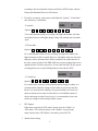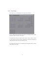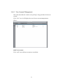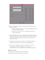
1
HDR-16EP 16-Cameras Digital Surveillance System USER MANUAL Date of Revision:Nov. 18, 2002 Hunt Electronic USA, Inc. Declaration Document This document is protected by copyright and related laws. Duplication in whole or in part of this document in any form or by any means is in violation of the copyright and related laws. If you have any questions or requests regarding this document, please contact us, and we will try our best to provide assistance. Product The HDR-16EP, 16-Camera Digital Surveillance System is protected by patent and related laws. Reproduction or imitation of any form is in violation of the patent and related laws. If you have any questions or requests regarding this product, please contact us, and we will try our best to provide assistance. Trademark The name and the trademark of the Hunt Electronic USA, Inc. are protected by trademark and related laws. Duplication in whole or in part of the name and/or trademark in any form or by any means is in violation of the copyright and related laws. Service All our customers are protected by consumer protection and related laws. Please contact us for any questions and requests. We will be glad to serve you. If you are not yet a customer, we will be pleased to introduce this high quality product to you; please contact us for further information. Others The “Window NT”, “Window 95” mentioned in this document are the trademarks of Microsoft; the “Pentium” belong to Intel; other trademark rights are the properties of the individual companies. Hunt Electronic USA, Inc. Address: 978 W. 10TH Street Azusa, CA91702 Telephone: (626) 812-8868 Website: www.huntcctv.com E-mail : Fax: [email protected] 2 (626) 812-8828 INDEX DECLARATION .......................................................................................................................................2 INDEX.........................................................................................................................................................3 I. LIST OF CONTENTS .........................................................................................................................4 II. PRODUCT CHARACTERISTICS....................................................................................................5 III. INSTALLATION ..............................................................................................................................6 3-1 Hard Disk Installation.........................................................................................................6 3-2 Connect to Monitor .............................................................................................................6 3-3 Connect to Camera..............................................................................................................6 3-4 Other Connections...............................................................................................................6 IV. OPERATION ...........................................................................................................................7 4-1 Booting Up...........................................................................................................................7 4-2 Main Screen .........................................................................................................................8 4-3 Display Mode.......................................................................................................................9 4-4 Hard Disk Free Space .......................................................................................................10 4-5 Playback ............................................................................................................................11 4-6 System Settings ..................................................................................................................14 4-7 Remote Functions ..............................................................................................................27 4-8 Backup Solution: Swap Removable Hard Disk.................................................................39 4-9 Backup Solution: CD-R/RW Recorder ..............................................................................46 V. OTHER INFORMATION ................................................................................................................49 5-1 Specifications.....................................................................................................................49 5-2 Q & A .................................................................................................................................50 5-3 Maintenance ......................................................................................................................51 5-4 Warranty ............................................................................................................................51 5-5 Customer Service...............................................................................................................51 3 I. LIST OF CONTENTS Items list included in the shipment package for customers to verify. HDR-16EP 1. 2. HDR-16EP Mouse 1 Unit 1 pc 3. 4. 5. 6. Key for Removable Hard Drive HDR-16EP User Manual Power Cord Warranty Card 1 pc 1 pc 1 pc 1 pc Please keep the original packaging in case parts need to be shipped back for service. Reminder: HDR-16EP package does not include a VGA surveillance monitor. The monitor (XVGA, 1024*768) can be purchased separately at various computer stores. 4 II. PRODUCT CHARACTERISTICS OPTIMUM REPLACEMENT FOR TIMELAPSE RECORDER The traditional Time-lapse Recorder is the mechanical device. It is very easy to break down after long time operation and causes many problems such as: the over used magnetic heads which cause blurred image; tapes need to be changed often and manually; the recording time is not long enough; the management of recorded tapes is complicated; not efficient when trying to locate the data needed; recording a huge amount of useless images, etc. HDR-16EP adopts the digital recording technology. The quality of images will not deteriorated with time. With its high compression rate, storage time will last up to months under normal application. The overwrite operation mode will overwrite the earliest data, and no more tape change required. Motion detection function will enable the recording only when there is motion of the objective, and makes the system and data retrieval more efficient. HIGH RELIABILITY The normal PC digital surveillance system adopts the MS-Windows operating system. The system crashes frequently, which makes the negative unreliable impression on digital surveillance system. HDR-16EP adopts Embedded Operating System (Non PC type). The advanced DVRonChip technology shrinks the entire system into a tiny flash module, which makes the system more reliable. Even when power failure, the system will re-boot and return to normal operation in less than one minute. MULTI-FUNCTION One set of HDR-16EP = Time-lapse Video Cassette Recorder+ Multiplexer processor + Motion Detection Processor EASY FOR OPERATION With such high reliable structure, HDR-16EP will meet your requirements as a multi-function device. Moreover, the GUI (Graphical User Interface) is also user-friendly. Customers will find this qualified security system is very easy for operation. 5 III. INSTALLATION 3-1 Hard Disk Installation 1. Insert the Removable Hard Disk to the rack, and make sure it is well mounted. Lock the hard disk drive with its key. 3-2 Connect to Monitor 1. 2. 3. Place the monitor that you purchased. Connect the VGA cable (with D-type, High Density, 15 pins plug) to the VGA port on the back of the HDR-16EP. Plug in the power cord of the monitor. 3-3 Connect to Camera 1. 2. 3. 4. Mount and adjust the cameras. This manual does not instruct you how to install, set up, or adjust the camera. Please refer to other books/manuals or ask your camera supplier. Connect the camera to the HDR-16EP with a 5C2V coaxial cable. Video input connectors for HDR-16EP are BNC female type. If cable with F connector to be used, a “BNC to Female” connector is needed. HDR-16EP uses 4 capture cards. CH1-CH4, CH5-CH8, CH9-CH12, CH13-CH16 is on the same card. Please don’t mix plug color cameras and B/W cameras on the same board to keep the best video quality. 3-4 Other Connections 1. Connect the power cord to the power socket on the back panel. 2. Connect the PS/2 mouse to the PS/2 mouse socket. 3. The operation of HDR-16EP doesn’t need the keyboard. 6 IV. OPERATION The operation procedures are as follows: 4-1 Booting Up 1. Push the Power Button (Open the front panel, then press the button). HDR-16EP 2. If all the installation procedures are correct, the system will boot up and show the main screen as follows. 7 4-2 Main Screen Date/Time HD Free Space Recording Status IO Status System Settings Display Mode Full Screen Monitoring Playback The above picture is an example of the main screen. On the right of the screen is the “status display”. From top to bottom is Date/Time, Hard Disk Free Space, then followed by 3 columns and 16 rows, which are Recording Status (1st column), DI Receiving Status (2nd column), and DO Output Status (3rd column). On the bottom of the screen, from left to right are “7 Display Modes”, “Full Screen Monitoring” icon, “Company logo (Hunt)”, “Playback” icon, and “System Settings” icon. All the functions are operated by icon clicking. The following graph shows the camera number related to the location on the screen. 1 2 3 4 5 6 7 8 9 10 11 12 13 14 15 16 Please note that whenever you click this Main Screen. icon, the system will return to the 8 4-3 Display Mode The 7 icons on the bottom of the Main Screen are Display Mode selections. The 7 icons are 4 splits, 6 splits, 8 splits, 9 splits, 10 splits, 13 splits, and 16 splits. The default display mode is 16 splits. The camera displayed on each split mode could be modified through the system setting menu. Besides the different kinds of split modes as mentioned above, user could use mouse to click any split screen to show the full screen of that specific camera as the figure below. In the full screen mode, the “Company name: Hunt” on the bottom of the screen will be replaced by the “Screen Adjustment Parameters”, which are “brightness”, “contrast”, “chroma”, and “saturation”.\ In the full screen mode, on the lower right of the screen, it will pop up the PTZ control icons, which include “Zoom in”, “Zoom out”, “Auto Focus”, “Focus Near”, “Focus Far”, “PTZ Speed”. Remark: Only when there is Speed Dorm connected, the PTZ control icons will show up. Zoom In Zoom Out Focus Far Focus Near Auto Focus PTZ Speed Contrast Brightness Chroma Saturation 9 4-4 Hard Disk Free Space On the right of the Main Screen, there are two Hard Disk pictures(HDR-16EP supports two Hard Disks). On the right of the hard disk picture, there is the number in color with a “%” sign, which means the available hard disk space. When you start using a new hard disk (e.g.: a hard disk with capacity 80GB), the display will show a number very close to 100%, and the color will be BLUE. However, as recording continues, the available space will diminish. When the remaining available space is less than 4GB of the total capacity, the display color will change to ORANGE. In the case of 80GB hard disk, the color change will happen when the disk space has only 5% available. This serves as a warning message that the system will soon enter the Recycle Mode; which means, the earliest recorded data will be replaced with the newest recording data. If you would like to keep all the data, this is the time to swap a new hard disk. If the disk hasn’t been changed and the recording continues, the system will eventually go into Recycle Mode when there’s only less than 1GB of hard disk space left (for a 80GB hard disk, this means space less than 1.25%), and the number shows “Hard Disk Space display” will turn its color into RED. Refer to the figure below. It means there is only one hard disk installed, and the available space of this hard disk is 80.7%. of the total space. 10 4-5 Playback 4-5-1 Enter Playback Mode When you click this icon, the system will display the screen as follows: 4-5-2 Select Playback Period You can use the mouse to select the “Time-segment Directory” in the upper left corner of the screen. Time-segment Directory only shows “Playback” when it is not opened. When you click this symbol, + it will shows the listing CAMERA for cameras 1 to 16. Clicking on the desired camera will show Date、Time to select. The Time-segment Directory is divided into the listings of “10 minutes” segment. When you click the specific time, the Playback will start from the beginning of that segment. 4-5-3 Image Quality Adjustment If you are not satisfied with the quality of the playback images, you can use the “Brightness” and “Contrast” controls in the upper left corner to adjust the picture 11 quality. 12 4-5-4 Playback Control Buttons In addition to “Brightness” and “Contrast” controls, there are more option buttons on the playback mode as follows: PLAY : To start viewing the images at normal speed. PAUSE : To freeze an image. You can also pause by clicking the screen. STEP PLAY : Click to view one frame at a time. INVERT : To show picture in complimentary colors. FIT TO WINDOW : To maximize the picture to the size of the screen. RESET TO DEFAULT : To cancel all special effects and reset to original settings. COPY TO FLOPPY : To save selected single picture into floppy. RETURN TO MAIN SCREEN: Return to main screen display CD/RW Backup: Click to enter CD/RW backup Screen 13 4-6 System Settings 4-6-1、Enter System Settings Screen Click here to enter the system setting screen 1. Click the System Setting icon. System will show a screen as follows for user to key in the username and password. 2. Use mouse to click the “keyboard” icon on the right of the “User Name” column. System will show up a “keyboard figure” as follows for user to key in the username (the pre-set username is “admin”). If the false data is entered, click the “Clear” icon to delete the old data, then key in the new data again. After finishing the operation, click the ”OK” button. 3. Use the same way as above to key in the password (The pre-set password is “1111”. 14 4. If the username and password are correct, click the “OK” button on the “User Login” screen, then the system will enter the system setting screen. 5. When you enter the system setting screen, there are 6 icons on top of the 、 screen. Each icon represents one sub-page. They are 『Camera Setup』 、 『User』、 『Date/Time』 、 『Network』 、 and『DI/DO』. 『Split』 6. When you enter the system setting screen,the default sub-page is『Camera Setup』. 7. When you complete all the setting, you could click the on the upper right corner, then system will ask if you would like to save all the settings. 15 4-6-2 Camera Setup 1. Please select the camera you would like to do the setting. 2. Camera Name: You could use the “keyboard figure” icon on the right of “Camera Name” column to key in the description for the camera. 3. Enable/Disable: If the channel is not connected to camera, please set “Disable”. If it’s connected, please set “Enable”. 4. Video Format: The video format of 16 cameras must be the same. Therefore, no matter which camera you choose for setting, all the camera settings will be changed to the same as the setting you make on that camera. Options: NTSC 、 PAL 、 SECAM The Video Format of each country is different. Please adjust the setting 16 according to the local standard. Taiwan and USA use NTSC format; whereas Europe and Mainland China uses PAL format. 5. For all the 16 cameras, each camera could adjust the “Quality”, “Frame Rate”, and “Sensitivity” individually. 5-1 Quality: Options: 10 、 20 、 30 、 40 、 50 、 60 、 70 、 80 、 90 、 100 User could adjust the quality of recording. The higher the number, the better the quality. However, the higher quality setting will consume more hard disk space. 5-2 Frame Rate: Options: 0.2 、 0.5 、 1.0 、 2.0 、 3.0 、 4.0 、 5.0 、 6.0 、 7.0 、 8.0 User could adjust the frame rate for recording. The higher the number, the higher frame rate will be recorded. However, with higher frame rate, the hard disk space will be consumed faster. Please remember: the total frame rate of the entire system is limited. For HDR-16EP, the system recording frame rate is depended on the CPU that system uses. If it uses the Intel P4-2.4G, the system recording frame rate is around 100fps(Frame per Second) for NTSC. 5-3 Sensitivity: Options: 10 、 20 、 30 、 40 、 50 、 60 、 70 、 80 、 90 、 100 User could set the sensitivity of the motion detection during recording. It is recommended to adjust the setting to 100 in order to prevent any data lost. However, in some special conditions, the system continues to record even when no motion has occurred. It will results in a considerable amount of useless data being recorded. In such case, it is recommended to lower the sensitivity setting to avoid wasting hard drive space. 6. PTZ Support If the camera supports the PTZ control, please select the “Enable” on “PTZ Status” icon, otherwise please select “Disable”, then select the camera model on the “PTZ Model” icon and key in the PTZ ID. 7. Motion Sensor Setup: 17 It is used to set the Motion Sensor Area。 7.1 Motion Sensor Area: Click for the Detection Area,then use mouse to drag the motion detection windows on the screen. 7.2 No-Detection Area: Click for the No-Detection Area,then use mouse to drag the area which do not use motion detection. 7.3 Set All: Click to set all the screen as the motion detection area.。 7.4 Clear All: Click to set all the screen as the non motion detection area.。 8. Recording Schedule Setup: Refer to the Recording Schedule Table below. There are 7 rows and 24 columns in the schedule table, which represents 7 days and 24 hours. There are three Recording Mode, 1. Fully Recording. 2. Motion Sensor Recording. 3. No Recording. First, you could choose the Recording Mode button on the left of the schedule table, then use mouse to drag the area on the table for each recording mode. 18 4-6-3 View Setup Click “Split” icon, it will display the view setup screen as follows. For the 7 display modes mentioned in the section 4-3, the display content is setup through the “Split” icon on the screen above. For the table above, there are 4 splits, 6 splits, 8 splits, 9 splits, 10 splits, 13 splits, 16 splits setting screen. Please click the “small block” on the split screen, then you could modify the camera showed on each split screen. On the right side of the table, it’s an example for the description of the 16 cameras when doing the view setup. 19 4-6-4 User Account Management This section describes the “remote access privilege” setup procedures for the user account. Click “User” icon, it will display the screen for user account management as follows. [Add User Account] Click “Add” icon to add user account as screen below. 20 1. There are 2 system pre-set accounts. The usernames and passwords for these two accounts are as follows. 1-1 Username: “admin”; Password: “1111” is for system management account. This account could not be deleted. 1-2 Username: “net”; Password: “1111” is for normal user account. This account could be deleted. 2. When login through “admin” account, administrator could operate the function to setup the other administrator account, or the privilege of the normal user account. The administrator account could be granted to enter the setup manual, while normal user account not. 3. The privilege of each account is for remote access, which includes “Monitor”, “Playback”, and “Dial-in Access”(Access the system through modem). 4. First, choose the “Administrator Account” or “Normal User Account” first. Set the privilege of “Monitor” and “Playback” on each camera. Click “Dial-in Access” if you would like to access the system through modem. [Modify User Account] Click “Modify” icon to modify user account as screen below. The operation is the same as the “Add User Account” above. 21 [Delete User Account] Click “Delete” icon to delete user account. A screen will display as follows. Click “OK” if you would like to delete this user account. 22 4-6-5 Setting Date and Time 1 2 Use mouse to modify the date/time. After that, please click the “Set!!”. System will pop up the warning window as follows. Please click the “OK” to reboot the system. 4-6-6 1. 2. Network Configuration Select Enable or Disable to enable/disable remote monitoring function. Click Up & Down buttons to enter IP, NetMask, GateWay; then click “Set!!” icon. 23 3. After click the “Set!!” icon. System will show the warning window as follows. Please click the “OK” to reboot the system. 4-6-7、DI/DO (digital control signal input and output) 1 DI/DO digital control provides the three configurations as follows. (1). One IO-0404B module, which includes 1 board (for internal connection), and 1 cable (for internal connection). (2) Two IO-0404B modules, which include 2 boards (for internal connection), and 2 cables (for internal connection). 24 (3) One IO-1616 module, which includes 1 board (for internal connection), 4 cables (for internal connection), 1 board (for external connection), and 1 cable (for external connection).. 2 DI control options: 2.1 Disable: Disable the “control signal input”. 2.2 NC (normal close): signal loop is normally closed; if loop becomes 2.3 3 opened, then starts recording. NO (normal open): signal loop is normally opened; if loop becomes closed, then starts recording DO control options: 3.1 Disable: Disable the output signal. 3.2 3.3 Enable: Enable the output signal. The signal duration can be set to 0.1, 0.5, 1, 2, 5, 10, 20, 30, and 60 minutes. Duration: Setting the duration time. 25 4. No matter it’s DI status change or image motion, it all counts as Event happening, so it will start the recording, If the DO is enabled, the DO status will also be changed if the event happens. Please refer to the graph below. DI Status Change Image Motion Event Happen Start Recording DO Status Change 4-6-8、Exit the System Setting Screen After finishing all the necessary settings, please click on the upper right corner of the System Setting Screen. It will show the figure below. Click “Yes” if you would like to save the setting change you made. 26 4-7 Remote Functions 27 4-7-1、Remote Monitoring through Local Area Network Ethernet PC SuperVision [Administrator] Decide an IP address in the local area network. Follow the instruction in 4-6-6 “Network Configuration” to set up HDR-16EP, then connect HDR-16EP to the local area network. Inform user the IP address, username, and password. [User] 1. Get HDR-16EP IP Address from administrator. 2. Open Web Browser from a PC in the same local area network. 3. Enter the IP Address of HDR-16EP. 4. Click the “Single View” option, then system will show the icons for requesting username and password information. Use the username “net” , and pre-set password “1111” to login. 5. Click any camera option, then you could start the live remote monitoring. 6. Besides the “Single View”, you could also choose “4 split” or “16 split” to do the live “4 splits” or “16 splits” remote monitoring. 28 4-7-2、Remote Monitoring through the Internet via Modem Modem ISP A RAS Internet ISP B Router Ethernet Modem PC SuperVision [Administrator] To allow users to do the remote monitoring through Internet, Administrator of HDR-16EP needs to apply for a fixed line (leased line or ADSL), and get the fixed IP address from the ISP (Internet Service Provider). Please follow the instructions in section 4-6-6 “Network Configuration” to setup HDR-16EP, then connect HDR-16EP to the fixed line. [User] Connect the modem to the PC(The graph in the left side uses the Windows 98SE OS as an example). Open “My Computer” on Windows desktop. Double click on “Dial-Up Networking”, then select “Make a New Connection”. After finishing the modem setup, when it requests “ Type a name for the computer you are dialing.”, enter your ISP name. (In this example, the ISP is Hinet) Click on “Next” to continue. 29 Enter the dialing number provided by ISP. (For example, the number is 03-4121234), Then, click “Next” to finish the setting. After completing the setting, open “Dial-Up Networking” window, you will see the new icon. (“Hinet” icon, in this example) Double click this icon, then enter the ISP account and password as left graph. You can select “save password” to let Windows save the password. Click on “Connect” to start dialing. After successful connect, the user’s PC will be assigned an IP Address from the RAS (Remote Access Server) of ISP. Users can open the Web Browser now, enter HDR-16EP IP Address (Refer to 4-6-6), and wait for several seconds (time for loading program) to start the remote monitoring function. 30 4-7-3、Remote Monitoring when HDR-16EP Connects to Modem Modem Modem PC SuperVision Similar to dialing up to ISP (Internet Service Provider) for connecting to internet as the previous section, through modem to connect to HDR-16EP(direct dial-in) is another way to do the remote monitoring. The only difference is that direct dial-in uses HDR-16EP to replace the function provided by ISP RAS (Remote Access Server) originally for setting up the connection. [Administrator] 1. Decide an IP Address, and follow section 4-6-6 “Network Configuration” to set up HDR-16EP. 2. When booting up HDR-16EP, press “Del” key on the keyboard to enter BIOS 3. 4. setting screen. Under the “Integrated Peripherals” menu option, set “Onboard Serial Port 1” (Port A) to “Enabled” (or Auto,, or 3F8). Connect the Modem to HDR-16EP COM1 interface. Apply a regular telephone line (PSTN), and connect the modem to the line. 5. Turn on the power of the modem, then turn on HDR-16EP。 6. Follow the instruction in section 4-6-4 “User Management” to set the password in “Dial-In Access” column. [User] Open “My Computer” on Windows desktop. Double click on “Dial-Up Networking”, then select “Make a New Connection”. Follow the step-by-step instruction to set up modem. When it requests, “Type a name for the computer you are dialing.”, enter “HDR-16EP”. Click on “Next” to continue. 31 Enter the phone number of the modem connected to HDR-16EP. Click on “Next” to complete the setup. After completing all the setup procedure, open “Dial-Up Networking” window, you will see the “HDR-16EP” Icon。 Double click the “HDR-16EP” Icon, then enter the dial-up username and password as left graph. The username is “dialup”, and the password is provided by administrator (refer to 4-6-6). You can select “save password” to let Windows save the password. dialing. Click on “Connect” to start Users can open the Web Browser now, enter HDR-16EP IP address, and wait for several seconds (time for loading program) to start remote monitoring function. Additional Information: After successful connecting to modem, the PC will be assigned an IP Address, which is the number next to HDR-16EP’s IP Address. For example, if the IP address of HDR-16EP is 140.113.17.154, then 140.113.17.155 will be assigned to the PC. 32 4-7.4 Remote Playback Installation Besides the remote monitoring feature mentioned in the previous section, HDR-16EP also provides the Remote Playback function. To be able to run Remote Playback, a “player” program needs to be installed on user’s computer. The “player” program can be downloaded from HDR-16EP web page as follows. Click on “Download Player” option, a “Download Files” dialog window will pop up as the bottom right graph. Select “Execute this program from the current directory(R)”, then click “OK” button. A warning dialog window will pop up. Click on “Y” (Yes) on the warning dialog window, and select “Next” on all the following dialog windows. Then click on “Finish” on the last window as figure below to finish the installation of Remote Playback function. After the successful installation, user can start to use the Playback function on the HDR-16EP web page. Also, a Local Playback icon will appear on the window desktop as the figure below. 33 Notice: If there is a previous installed Remote Playback program on your machine, you will need to process the same installation twice – the first time for removing the original program, and the second time for installing the new version of the remote playback program. 34 4-7.5 How to use Remote Monitoring and Remote Playback After the installation, you can start using Remote Monitoring and Remote Playback functions by clicking on the icons on the HDR-16EP web page. following screen will be displayed: The [Remote Monitoring Function]: There are three kinds of display modes for remote monitoring, which are, Single View, 4 Split, and 16 Split. “SingleView”: User could choose one of the 16 cameras for remote monitoring as graph below. 35 “4 Split”: User could monitor 4 split screen at the same time as the graph below. The default view is Camera 1,2,3,4, Camera 5,6,7,8, Camera 9,10,11,12, and Camera 13,14,15,16. User could also change the view position of each camera from the “Custom View” column. “16 Split”: It will display all the 16 cameras in the screen. [Remote Playback Function] First select a camera, then select the recording date and recording time (hour:minute). Click on button to start searching the recorded video. 36 System will start to play the recorded video if recording file found at the selected time. However, if there is no recorded video at the selected time, system will do the forward searching to play the next recorded video. The following selection can be used during the video playing. Enlarge the video image Back to the original image size Pause Play Search for video 30 seconds forward Search for video 30 seconds backward Notice: There may be no record found when searching 30 seconds backward. In this situation, system will keep searching, 30 seconds backward each time, until the first recorded video found, then play it. That means when you click , sometimes, system may skip for more than 30 seconds. 37 4-7.6 How to Use Local Playback From the remote monitoring/remote playback web page listed in the previous section, select to download the current playing record with an image file (*.MP4) and a relative index file (*.CVX) to the selected directory. Note that these two files must be saved in the same directory. Normally, a record file contains the recording data no more than 10 minutes. The Local Playback icon will be created on the windows desktop during the installation of Remote Playback, mentioned in section 4-7.4. Double click the Local Playback icon on the window desktop to start Local Playback (DVR Player) program. Click on the icon on bottom right to select and open the index file. After the file opened, select from the following icons to control the video playing. Play Pause Stop and rewind to the beginning Enlarge image size Reduce image size 38 4-8 Backup Solution: Swap Removable Hard Disk If it is necessary to save all the recorded data, the most economical way will be to store data by swapping the removable hard disk. Normally, DVR uses storage media such as hard disk, tape driver, or recordable optical media (MO, CD-RW, DVD-RAM…etc.). Tape : A tape driver is very complicated to operate. It will take more than 10 minutes to search the specific data. The cost is also very high: a tape driver of 100GB capacity costs thousands of US dollars. Optical Media : The small capacity as 0.65GB to 4.7GB will be the problem of recordable optical media. To store 100GB data, it will need more than 20 optical media with the highest capacity, such as DVD-RAM. An optical storage disk will cost more than ten US dollars, so it will cost more than two hundred US dollars to store 100GB of data. Another disadvantage is that it will be annoying for constantly swapping the optical disk. The market price for 80GB hard disk is less than US$ 100. It will be the most economic choice for the backup solution. It also has many advantages such as convenience, easy storage, and fast data tracking. It is the best available solution for backup purpose. HDR-16EP is very suitable for using removable hard disk as it is very fast to boot up and format disks. In chapter 4-4, we discussed how to change the removable hard disk. The following is just a quick review again. As recording continues, the available hard disk space will diminish. When the remaining space is less than 4GB, the display color will change to ORANGE. This serves as a warning message that the system will soon enter OVERWRITE mode (i.e. the earliest data will be replaced with the new data). If you would like to keep all the data, this is the time to swap a new removable hard disk. Please write down the dates for the recording data in the old hard disk before swapping hard disk. Push down the power switch on the front panel of the system. The system will enter Shut Down procedure and turn off power automatically. When shut down procedure is completed, you could use the hard drive key to take out the removable hard disk and mark the dates of recording data in the hard disk 39 for retrieving purpose in the future. Insert the new removable hard disk (purchased from the dealers authorized by Hung Electronic USA, Inc.) and lock the hard drive with key. Turn on the power switch. The system will recognize the new disk and request to format it. Click “Yes” to accept disk formatting which will take less than one minute. The system will re-boot and enter in the normal recording mode. 4-8-1、If the new hard disk is inserted to the system HDR-16EP supports 2 Hard Disk. If you insert the New HD(either 1 HD or 2 HD) into the system, after system booting, it will show the figure as follows. Attention: If there is any old HD(w/ recorded data inside) inserted into the system, it won’t show the figure above. Please refer to the following section 4-8-2 for the old HD operation. 1. Click the “Disk Management”, it will show the figure as follows. Remark: The following figure takes “insert 1 new HD” as an example. Selection Icons 40 2. Click “Format” on the right of the screen, then system will start to format the new hard disk. After finishing the format, the “selection icons” will become “available”. Please refer to the figure below. Use the “selection icons” to choose the cameras you would like to be recorded in this new formatted HD. Click the “save” icon on the bottom right of the screen, then the system will reboot automatically and enter the monitoring screen. Selection Icons “Save” Icon 3. If you insert 2 new HD at the same time, the operations are similar to the procedures above. After formatting, it will show the figure as follows. Please use “Selection Icons” to split the cameras to two new formatted HD, then press the “Save” icon to reboot the system as the procedure 2 above. 41 Selection Icons Selection Icons 4-8-2、If the old disk is inserted to the system. After system booting, it will show as follows. 1. If you click “Play Only” icon , it will show the figure as follows. 42 All Disk Icon HD Select Icon Playback Icon Choose the HD you would like to playback through “HD Select Icon”, then click “Playback” Icon, it will show the playback screen as follows. The playback procedures are the same as the Section 4-5(Playback). If there are two old HD(w/ recorded data inside) inserted into the system at the same time and also there is no “overlapped camera” from the cameras 43 stored in these two HD, the “All Disk” icon will pop up also. User could click the “All Disk” icon, then click the “Playback” icon to enter playback screen to play the images stored in these two HD. 2. If you click “Disk Management” icon , it will show the figure as follows. “Save” Icon If there are two old HD inserted into the system at the same time and also there is no “overlapped camera” from the cameras stored in these two HD as the figure above, the “Save” Icon will pop up. User could click the “Save” icon on the bottom right of the screen, then the system will reboot and start the normal operations and record the data in these two HD. However, if you insert two old HD into the system and these two HD have the “overlapped camera” as the figure below. The “Save” icon won’t pop up. 44 Selection Icons “Save” Icon Please use the “Selection” Icon as above to remove the “overlapped camera” from one of the HD, then the “Save” icon will pop up again. Click the “Save” icon, the system will reboot automatically and start the normal operations and record the data in these two HD Remark: * If the HD is entering the “recycle mode”(the space of HD is full of the recording data), system will delete the recording data from the first date, then record the data on these available space. After the space of 1st day is full, system will start overwriting the space of the 2nd day, and so on. * As the figure above, for the “overlapped camera” which are removed from the HD, the recording data of these “overlapped camera” still keep in the HD, until it’s been overwritten when HD enter the “recycle mode”. 45 4-9 Backup Solution: CD-R/RW Recorder When users try to save part of the video files to be used for evidences or references, the most convenient way is to record to CD-R or CD-RW, since almost every computer has CD-ROM. HDR-16EP provides a friendly user interface to process CD-R/RW recording. The video playback program will also be copied to the CD-R/RW as well as the video files. 4-9-1 CD-R/RW Recorders 1. HDR-16EP supports both internal and external CD-R/RW Recorders. 2. Internal CD-R/RW Recorder uses the IDE interface. The CD-R/RW Recorder needs to be set to ”Primary IDE Slave”. Recommend models: Aopen32x12x48, LiteOn32x12x40, BENQ CRW2410A. 3. External CD-R/RW Recorder with USB interface. Before DVR turns on, please use USB cable to connect the CD-R/RW Recorder with USB interface of DVR, then turn on the DVR to use external CD-R/RW Recorder. Please note that HDR-16EP does not support USB Hot Plug, which means if you connect the CD-R/RW Recorder to DVR while the DVR was already tuned on, the DVR will not recognize the CD-R/RW Recorder. Recommend models: BENQ 6406 4. If you can not find the CD-R/RW Recorders as we recommend above, you can try the similar models. They will also be compatible with HDR-16EP. 4-9-2 CD-R/RW Burning Procedure 1. How to enter user interface of CD-R/RW burning procedures: In the Playback screen, click on the “CD like” icon on the top right corner to enter the interface of CD-R/RW burning procedures. It will show the graph as follows. 46 Selected video files CD-R/RW models to be selected Video files stored in the hard drive Message Total size of the selected files Speed of burning 2. Blank (Clean up) CD-R/RW Execute Burning Process Blank CD-RW: If the CD-RW is used, please execute “Blank” procedure first. Input the CD-RW to the CD-R/RW recorder, click on to start the clean up process. After it is done, the Message area will display “Done”. If the CD-RW is the blank one, you do not need to execute this process. 3. Select files to burn to CD-RW Expand the hard drive directory, drag the mouse to select recording files. (by year, month, day order). Then click on to select them. The total size of the selected files should not exceed 600MB. 47 4. You can browse the other directories (dates) to continue the file selection. 5. Click on the button on the bottom left corner to choose the burning speed. The default speed is 6 times burning. 6. Click on button, the system will first check if there is a blank CD inside the CD-R/RW recorder. If not, the system will request for the replacement or insert a blank CD. When there is a blank CD inside, the system will convert the selected files into standard ISO 9660 format files (Make Iso), then burn the files to the CD. 7. If the recorded CD has problem, it might be due to the reasons below: (1) The blank CD is in bad quality: Replace the new CD with better quality. (2) The CD-RW is reused too many times: Replace with a new CD. (3) The CD-R/RW recorder cannot process high-speed burning: Try to reduce the speed. Especially for external CD-R/RW recorder with USB interface, please try to use 6 times speed if possible. (4) The blank CD does not support high-speed burning: Please reduce the speed, or replace with high-speed compatible CD. 48 V. OTHER INFORMATION 5-1 Specifications Model: HDR-16EP System: Operation System Video Input Video Output Video Format Compression User Interface Security WatchDog Embedded Linux 8/16 BNC connectors D-type VGA connector NTSC/PAL/SECAM MPEG-4 User friendly graphic user interface operated by mouse Multiple passwords protection Both software and hardware watchdogs Monitoring Mode: Frame Rate 120 fps(max.) for whole system under NTSC format Resolution 640x480, scale up to 928x695 Split Style 1/4/6/9/10/13/16 HD Storage Remaining Display Yes Video Loss Detection Yes Recording Mode: Resolution 320x240, 240x180 Recording Speed 10 degrees per channel, 120 fps(max.) for whole system Hard Disk Storage Capacity Standard 80G IDE HD. Upgradeable to total two 80/120/160/200GB HDs Pre-Schedule Recording By 7days x 24hours, set each hour as: recording by motion, continuously recording, non-recording Date Code Recording includes time/date information. To prevent date code from being modified Remote Functions: Network Access Monitoring by Web Playback by Web Download and Local Play LAN/ WAN/ Internet, by Ethernet/ Modem By Java technology. No need to install software. Password protection By MPEG4 streaming. User can select any recording time to playback Yes Alarm Functions: Alarm Input Alarm Output IO & Camera Relations Automatic Speech Dialing 16 NC/NO digital input (Optional: IO-1616, IO-0404) 16 NC/NO relay out (Optional:IO-1616, IO-0404) 1-1, 1-many, many-1, many-many Speech recording, 3 sets of auto dialing numbers(Optional: DA-712) Others: Backup Solution PTZ Camera Control Removable HDD, CD-R/RW, Floppy Support well-known brand PTZ cameras * The specifications are subject to change without notice. 49 5-2 Q & A 1. Q. Why does it still record a lot of images even though the motion detector has been triggered? A: The digital recording system is very sensitive. The system can detect even the tiniest motion that our eyes can't perceive. The problem can be caused by: 1. Flickering fluorescent lights (when traditional 120 Hz ballast are used) 2. TV or computer screen 3. Low quality cameras 4. Poor connection between HDR-16EP and cameras, or interfered with other objects. It is recommended not to align the camera directly at fluorescent lights, TV, or computer screens. The use of better quality fluorescent lights (with electronic ballast), monitors, and the cameras are suggested to use. When cameras being installed, please make sure the quality of cables, connections, and workmanship. Avoid placing the system close to a compressor (fridge), or a motor (washing machine) that might cause magnetic interference. 2. Q: Why do the recorded images have a somewhat reddish or bluish tone? A: The associated camera(s) have a problem with color tone. We recommend to contact with the camera supplier to adjust the settings for you. 3. Q: What will happen if there is a power outage (cut)? Do I have to do anything? A: If a power outage should occurs, there will be up to 10 minutes of data loss. When the power returns, the system will re-boot, restore data and go back to normal operation in approx. 1 minute. No special measures have to be taken to guard against a power outage. However, we do recommend the use an Uninterruptible Power Supply (UPS) with the HDR-16EP. This will help to avoid shortening the system life span and partial data loss due to the instability of power supply. Therefore, in order not to miss any important images, we recommend that the power supply of the cameras should also be connected to the UPS. 50 5-3 Maintenance 1. 2. Avoid placing the system in a high temperature or a high humidity environment and also away from the place with frequent vibrations. Operate the system under stable voltage. If possible, operate the system with a UPS (Uninterruptible Power Supply). 5-4 Warranty Hunt Electronic USA, Inc. provides one year warranty from the date of purchase against defects in materials or workmanship, when the HDR-16EP is installed and operated in accordance with the instructions provided in this user’s manual and is in normal use. Please note that the warranty is not covered under the following conditions: Warranty Card has been altered Damage caused by natural disasters Damage caused by transportation Damage caused by installing, repairing, operating and storing NOT according to instructions of this user’s manual The product has been repaired and serviced by non-Hunt authorized personnel No purchase date and product serial number on the Warranty Card, or the date and the serial number are incorrect 5-5 Customer Service Please contact your supplier with the Warranty Card for service when you have problem with your goods. Should you have any questions regarding HDR-16EP, welcome to visit our customer service department at: http://www.huntcctv.com/ 51