1
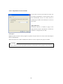
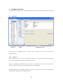
Control Center Std
User’s Guide
(v 1)
Contents
1.
2.
Product Overview ................................................................................................................... 6
1.1.
What is Control Center? ..................................................................................................... 6
1.2.
PC System Requirements ................................................................................................... 6
1.3.
Installation Program........................................................................................................... 7
1.4.
Program log in .................................................................................................................. 8
Control Center Monitor .......................................................................................................... 9
2.1.
Interface ........................................................................................................................... 9
2.1.1.
View area .................................................................................................................. 9
2.1.2.
Tool bar ................................................................................................................... 11
2.2.
Unit mode ....................................................................................................................... 12
2.2.1.
Making/deleting a sub folder ..................................................................................... 12
2.2.2.
Registering /deleting unit .......................................................................................... 12
2.2.3.
Revising information of unit ...................................................................................... 13
2.2.4.
Viewing image ......................................................................................................... 13
2.3.
View set mode ................................................................................................................. 14
2.3.1.
Registering / deleting view set ................................................................................... 14
2.3.2.
Viewing image ......................................................................................................... 15
2.4.
Map mode ....................................................................................................................... 15
2.4.1.
Map Editor .............................................................................................................. 15
2.4.2.
Registering/deleting map .......................................................................................... 17
2.4.3.
Viewing map............................................................................................................ 17
2.4.4.
Controlling device of map ......................................................................................... 17
2.4.5.
Arranging map window ............................................................................................ 18
2.5.
Monitor screen ................................................................................................................ 19
2.5.1.
Screen interface........................................................................................................ 19
2.5.2.
Screen division......................................................................................................... 19
2.5.3.
Full screen ............................................................................................................... 19
2.5.4.
Moving screen ......................................................................................................... 19
2.5.5.
Caption information ................................................................................................. 20
2.5.6.
Image transmission speed.......................................................................................... 20
2.5.7.
Image resolution....................................................................................................... 20
2.5.8.
Stream ..................................................................................................................... 20
2
2.5.9.
Event....................................................................................................................... 21
2.5.10.
Saving image ........................................................................................................... 21
2.5.11.
PTZ control ............................................................................................................. 22
2.5.12.
Audio control ........................................................................................................... 23
2.5.13.
Close all .................................................................................................................. 23
2.6.
Alarm log ....................................................................................................................... 23
2.6.1.
Event information .................................................................................................... 23
2.6.2.
Viewing image ......................................................................................................... 24
2.6.3.
Viewing Detailed Message ........................................................................................ 24
2.7.
Status & Action ............................................................................................................... 24
2.7.1.
Status& Action information ....................................................................................... 24
2.7.2.
Viewing image ......................................................................................................... 25
2.7.3.
Alarm notification setting at each unit ........................................................................ 25
2.8.
Automatic image switching .............................................................................................. 25
2.9.
Alarm pop up .................................................................................................................. 26
2.10.
Event search ................................................................................................................ 26
2.11.
Program user configuration .............................................................................................. 27
2.12.
Option setting .............................................................................................................. 27
2.12.1.
Caption ................................................................................................................... 28
2.12.2.
REC ........................................................................................................................ 30
2.12.3.
Alarm ...................................................................................................................... 31
2.12.4.
Layout manager ....................................................................................................... 33
Import/Export System Information ................................................................................ 34
2.13.
3.
Control Center Playback ....................................................................................................... 36
3.1.
Interface ......................................................................................................................... 36
3.2.
View area ........................................................................................................................ 36
3.2.1.
Tool bar ................................................................................................................... 37
3.3.
Opening unit/backup file .................................................................................................. 37
3.4.
Search ............................................................................................................................ 38
3.4.1.
Image information indication .................................................................................... 38
3.4.2.
Change of search section ........................................................................................... 38
3.4.3.
Channel selection ..................................................................................................... 38
3.4.4.
Calendar search ........................................................................................................ 38
3
3.4.5.
Log information indication & Search ......................................................................... 38
3.4.6.
Text search .............................................................................................................. 39
3.4.7.
Smart search ............................................................................................................ 40
3.4.8.
Thumbnail search ..................................................................................................... 41
Playback ......................................................................................................................... 42
3.5.
3.5.1.
Playback button........................................................................................................ 42
3.5.2.
Audio playback ........................................................................................................ 42
3.5.3.
Text......................................................................................................................... 42
3.5.4.
Time zone selection .................................................................................................. 42
Image control .................................................................................................................. 43
3.6.
3.6.1.
Zoom/Brightness/Contrast control ............................................................................. 43
3.6.2.
Image save............................................................................................................... 43
3.6.3.
Image print .............................................................................................................. 43
3.7.
Backup function .............................................................................................................. 44
3.8.
Backup Log function ....................................................................................................... 44
3.9.
DVrS unit search ............................................................................................................. 45
Option setting .............................................................................................................. 46
3.10.
4.
3.10.1.
Caption ................................................................................................................... 46
3.10.2.
Adjustment of screen division ................................................................................... 47
Configuration Tools............................................................................................................... 48
4.1.
5.
Interface ......................................................................................................................... 48
4.1.1.
Site Tree .................................................................................................................. 48
4.1.2.
Menu....................................................................................................................... 49
4.1.3.
Configuration page ................................................................................................... 49
Tools ..................................................................................................................................... 50
5.1.
Schedule Backup ............................................................................................................. 50
5.1.1.
Backup setup ........................................................................................................... 51
5.1.1.1.
Backup file name .............................................................................................. 51
5.1.1.2.
Password .......................................................................................................... 52
5.1.1.3.
Preservation...................................................................................................... 52
5.1.1.4.
Destination ....................................................................................................... 53
5.1.1.5.
Auto deletion setting ......................................................................................... 53
5.1.1.6.
Select backup data range.................................................................................... 54
5.1.1.7.
Backup Timetable ............................................................................................. 54
4
5.1.1.8.
System Tray icon .............................................................................................. 55
5.1.1.9.
Backup file ....................................................................................................... 56
5.1.2.
Backup status ........................................................................................................... 56
5.1.2.1.
Detailed information ......................................................................................... 57
5.1.2.2.
Detailed backup history ..................................................................................... 58
5.1.3.
Stop backup ............................................................................................................. 58
5.2.
Mini Player ..................................................................................................................... 59
5.3.
One time Password .......................................................................................................... 61
5.4.
File Converter2 ............................................................................................................... 62
5.4.1.
How to use File Converter2 program.......................................................................... 62
5.4.1.1.
Convert eye file(s) to jpg of bmp file(s) .............................................................. 63
5.4.1.1.1. Select Source ........................................................................................................... 63
5.4.1.1.2. Output file Type ....................................................................................................... 64
5.4.1.1.3. Destination Folder ................................................................................................... 65
5.4.1.1.4. Converting ............................................................................................................... 66
5.4.1.2.
Convert sequential eye files to a rec file. ............................................................. 67
5.4.1.2.1. Select Source and destination .................................................................................. 67
5.4.1.2.2. Converting ............................................................................................................... 68
5.4.1.3.
Convert sequential eye files to a avi file. ............................................................. 69
5.4.1.3.1. Select Source and destination .................................................................................. 69
5.4.1.3.2. Setting avi condition ................................................................................................ 70
5.4.1.3.3. Converting ............................................................................................................... 71
5.4.1.4.
Convert rec file to a avi file. ............................................................................... 72
5.4.1.4.1. Select Source ........................................................................................................... 72
5.4.1.4.2. Password File Login ................................................................................................ 73
5.4.1.4.3. Select time interval and channel information for avi ............................................... 74
5.4.1.4.4. Setting avi condtion ................................................................................................. 75
5.4.1.4.5. Destination Folder ................................................................................................... 76
5.4.1.4.6. Converting ............................................................................................................... 77
The contents of this manual can be different in accordance with Software upgrade and design/
specification can be partly modified without prior notice to user.
5
1. Product Overview
1.1. What is Control Center?
Control Center is managing software that can control max 1000 units installed in remote area.
It provides functions such as real-time monitoring, search and backup of recorded image and setting. It
also supports dual monitor and can monitor max 128 channels simultaneously. So effective search can be
done : It can be done with designated motion area, and text search is also possible.
It allows user to understand and deal with various situation of each unit. Also it provides function such as
recording and searching event. If event is triggered, relevant image can be pop-up.
It is to easily control many units classified according to view set and map.
1.2. PC System Requirements
Minimum
Recommended
CPU
Intel Pentium 4 / 3.0GHz
Core2duo E6750 or higher
Memory
1GB
2GB or higher
Video Card
128MB
512MB or higher
Resolution
1280 x 1024 (with 32bit color) or higher
HDD storage
80GB or higher
space
OS
Windows XP Professional(over SP2) / Window Vista Business(over SP1)
Others
DirectX 9.0 or higher
Control Center is optimized for XP (service pack2 recommended).
In case using the video driver which is provided from Microsoft, the display in user’s screen could be
seriously flickering and its efficiency can decrease, so do not use DirectX, or establish the up-to-date
driver which is provided from the video card manufacturing company.
6
1.3. Installation Program
1) Run “2.x.x.x Setup.exe” file in Control Center Setup CD.
In order to install Control Center, user account on local PC should be Administrator.
2) Click on “I Agree” button.
7
3) Choose components and press “Next” button. WESP SDK should be installed.
4) Select folder and press “Install” button.
1.4. Program log in
Click the “OK” button after inputting ID and Password. When login becomes correct, Control Center
program will run. The default user is “Administrator” and password is “admin”. The user‘s authority to
run program is restricted respectively.
8
2. Control Center Monitor
2.1. Interface
Tool Bar
MainView
(video/Map)
2.1.1. View area
It has unit explorer in the left part of screen, image or map in the center part of screen, event situation in
the lower part of screen. It is composed of total three view areas.
Unit Explorer
It shows unit, view set and map in tree list according to each mode. Register, edit and eliminate unit /view
set /map.
9
(Table. Tree Icon)
Icon
Function
The folder that manages registered unit.
Shows the unit which is detected and not registered in “My Units” at local network.
User can make the lower folder and manage it if user have registered unit.
Shows the unit which does not have HDD fails in connection.
Shows the unit which does not have HDD fails in log in.
Shows the unit which does not have HDD succeeds in log in.
When alarm signal comes in, it flicks for 5 seconds.
Shows all video channels of the unit are monitoring.
Indicates that a unit has HDD.
Indicates that a unit is DVrS.
Video Channel
Sensor
Relay out
Audio out (Talk)
View set
Map
Inside folder of map (channel, sensor, relay out and talk)
Main View
It shows monitor screen and map window according to each mode.
Event View
The event history shows event which occurs from the unit registered in “My Units” at real-time. The
Status & Action shows current event situation of each unit and control relay output, audio output device.
Click
button to lead to docking of event view.
10
2.1.2. Tool bar
There are buttons on top area, so user can make use of functions easily.
(Table. Control Center Tool Bar)
Button
Function
Hides “Unit Explore”
Hides “Event View”
Displays “Main View” with a full screen
Executes playback program
Executes configuration program
Can search stored events according to date, unit and category
Sets option menus.
Adds unit, view set and map.**
Changes information of unit, view set and map. **
Deletes unit, view set and map. **
Stores current monitoring status as view set. **
Renews information of unit tree (connection status, detected unit list, etc).
Monitors the registered unit and view set by auto switching mode.
Turns on/off alarm pop up.
Change frame rate.
Closes connection which is in monitoring, or closes all map windows.
Close a connection during monitoring or windows whether it is open or not.
Selects the map which will be located on the top part among many maps of map mode
Arranges maps with cascade.
Arranges maps with tile style.
~
Divides monitor screen by 1~64. (1, 4, 9, 13, 16, 25, 36. 49. 64)
Change resolution of monitor (In case of multi monitor, each menu exist).
Select the current monitor whether sequence switching is used or not.
Select the monitor whether alarm popup is used or not.
Confirms information of control center version.
(**This indication means only the user who has authority of setting control center is allowed to use)
11
2.2. Unit mode
It registers many units and manages them. User can easily register a unit searched by “Discover” and
showed in “Local Area Units” folder. User can understand unit connection status through icon.
2.2.1. Making/deleting a sub folder
If selecting “Add Folder” from pop up menu after clicking on “My Units” folder, the dialogue box where
user can input folder name will be indicated. When entering folder name and clicking “OK” button, new
folder will be created.
In order to delete folder, select the “Delete Folder” from pop up menu after clicking it. If there are
registered units in the folder that user wants to delete, they will be also deleted together.
2.2.2. Registering /deleting unit
If user drags and drops a unit from “Local Area Units” to “My Units” or chooses
“Add Unit” from
pop up menu after clicking “My Units”, user will see registration dialogue box. Or, select “Add” menu of
tool bar.
Registration of static IP unit
In order to register a unit by using “Add Unit” menu, input IP address and click “Find” button. At this
time user can change port number by clicking “Advanced” button if number of unit is not default 80. User
can bring server information through process of server finding. And then “OK” button will be activated.
Input user ID, password and click “OK” button.
User will see the detected units in the list by clicking on “Auto Detect” button. Select the unit that user
12
wants to register and input user information.
User will find basic information, if user drags and drops it from “Local Area Unit”. So just input user
information and click on “OK” button.
Registration of dynamic IP unit
User can manage a unit which has dynamic IP address with registration server. (About WRS registration,
please refer to 4.Configuration)
Click the “Find” button after selecting “Dynamic IP Address” radio button and inputting registration
server/serial number. When search process is done successfully, user will input user information and
register it.
Using group ID, the unit registered at Registration Server can be searched by selecting "Dynamic IP
Address" radio button, typing Registration Server, typing Group ID, and pressing "Find by Group ID".
Change of unit information
In order to change information of registered unit, select “Edit Unit” from pop up menu after selecting a
unit. Then a dialogue box will appear. Or select
“Edit” menu of tool bar, user can change port number
and user information.
Deletion of unit
In order to delete registered unit, select “Delete Unit” from pop up menu. Or select
“Delete” menu of
tool bar.
2.2.3. Revising information of unit
If selecting “Refresh” from pop up menu of unit tree or clicking “Refresh” button of tool bar, information
of registered unit and detected unit list at network will be renewed.
2.2.4. Viewing image
When unit is connected, the video channel of unit in tree will be shown. User can see live image on
monitor of “Main View” after selecting certain channel. If user drags and drops channel item to monitor,
an image will be displayed at the designated location. In order to see all channels of certain unit, select an
icon of unit, then all channels will be played and screen division will be changed according to number of
channel.
13
2.3. View set mode
When registering group of channels in “View Set”, user can easily manage them. Select “View Set” tab in
“Unit Explorer”.
2.3.1. Registering / deleting view set
Quick Save View Set
User can register the current monitoring at site mode as view set. After selecting channel, click
“Quick Save View Set” button of tool bar. Information such as current division, channel, frame rate and
resolutioin will be saved together with it.
Registration on the menu
When selecting “Add View Set” from pop up menu, the registration dialogue box is open. Or click on
“Add” menu of tool bar.
Edit View Set
When selecting “View Set” and then “Edit View Set” from pop up menu, the dialogue box is open. Or
click on
“Edit” menu of tool bar.
Delete View Set
When selecting “View Set” and then “Delete View Set” from pop up menu, the dialogue box is open. Or
click on
“Delete” menu of tool bar.
14
2.3.2. Viewing image
When selecting the registered view set or dragging and dropping it, screen is divided according to
division of view set and channel of view set is played.
2.4. Map mode
User can mange system relating to channel, audio out, relay out, and sensor by way of registering them in
the map. Select the map tab of “Unit Explorer”.
2.4.1. Map Editor
Run “Tools>Map Editor” in map mode.
15
(Table : Map Editor Tool Bar)
Button
Function
Add a Map
Save map information
Unit Tree
Display available map registration unit and device, which is available unit registration at only Monitor
program.
Toolbox
In case of putting submap/maplink at a map, add this icon by Drag&Drop.
Map Tree
Display tree type to view easily map configuration with the attached device. If you select item from a map
tree, “Properties” window will display edit available item.
Properties
Edit the item contents selected from a Map Tree.
(Table : The Icon Properties at Map Tree)
Icon
Type
Properties
Folder
None
Map
Map Name
Channel
None
Sensor
None
Relay
None
Audio
None
16
Register User Icon
As for icon, user can register the image which he/she wants to display. JPEG, GIF and BMP can be
registered.
User can execute this function in ‘Tools > Register User Icon’ of Map Editor Menu.
2.4.2. Registering/deleting map
Registration of map
Map Editor will be executed if user selects “Add Map” from pop up menu of map tree or just clicks on
“Add” menu of tool bar.
Edition of map
“Map Editor” will be executed if user selects “Edit Map” from pop up menu of map tree or just clicks on
“Edit” menu of tool bar.
Deletion of map
Select “Delete Map” from pop up menu of map tree or click on
“Delete” menu of tool bar.
2.4.3. Viewing map
If user selects the map in map tree, window of map will be opened.
2.4.4. Controlling device of map
Viewing image
If user selects the channel of “Channel(s)” folder of map tree or selects channel icon of map window, live
image monitor will be popped up.
17
Sensor
If sensor that is registered in the map is on, the sensor of the map will start flicking.
Relay out
If relay out that is registered in the map is on, relay icon of the map will start flicking. User can make
relay out on/off by clicking on its icon of the map.
Audio out
User can transmit audio to the unit by selecting audio out.
2.4.5. Arranging map window
User can arrange windows in
Select
cascade or
tile when user opens many map windows on screen.
if wanting to place specific map window on the top part.
18
2.5. Monitor screen
2.5.1. Screen interface
On the top part there is caption title. It has button for unit, name of channel, PTZ, and Audio control. To
the lower part of screen it shows time and event information.
(Table. Monitor menu button)
Button
Function
Stores live image (re4 file)
PTZ
Audio on/off
Closes connection of monitor
2.5.2. Screen division
The number of screen division is diverse (1/4/9/13/16/25/36/49/64).
2.5.3. Full screen
When selecting “Full Screen” menu
, the window of main view will be converted to the full screen.
Press Esc key if wanting conversion to the original mode.
2.5.4. Moving screen
Drag and drop an image while pressing the left button of mouse, if wanting to exchange image of two
monitors.
19
2.5.5. Caption information
Select the information to see from caption item of pop up menu.
<Note>
If the user selects QCIF mode to monitor under low leveled system frame rate would be also low.
In this case uncheck “caption” on option menu and it will raise frame rate.
2.5.6. Image transmission speed
User can control an image transmission speed with Frame Rate of pop up menu.
2.5.7. Image resolution
Change of resolution will be necessary to suit monitor size, if setting resolution “Auto”. The Selected
resolution will be applied regardless of monitor size, if setting specific resolution.
2.5.8. Stream
In case of monitoring the model supports Mpeg-4, it shows the selectable menu for stream as follow..
If it set to Auto, it shows adjusted resolution to capacity of PC and window size of monitor.
Unit serves the closest stream to the resolution required.
But, if it selects specific stream, it shows the stream as required irrelevant to window size & capacity.
20
<Note>
The below table shows the number of channel by each resolution with MPEG4 Stream which can be monitoring
from Control Center Program.
Resolution
Number of Channel
QCIF
32
CIF
8
HALF
4
FULL
2
(* In case of each stream with 30ips)
In case of MPEG4 Streaming from Control Center Monitor Program, It supports up to 60ips with full size
monitoring. And it will output each picture per second In case of user request more than 3 with full resolution.
The Control Center Program will not support maximum image output (support one picture per second), if the user’s
PC has lack of performance.
2.5.9. Event
When the “MD” occurs,
icon will appear. When the sensor is on,
icon will appear with sensor
number.
2.5.10. Saving image
Saving live image
Select “REC Start” from the pop up menu or click recording button
. The recording hour is also put on
record. The maximum storage hour is 10 minutes. User can set drive to store in REC tap of the “Tools>
Options” menu.
Saving still image
User can save current image as file format of bmp or eye with “Save As".
Eye file can be seen with
Microsoft Internet Explorer. User can select saving method and if automatic saving is selected, he can
select recording drive and file format for saving (If manual saving is selected, user will select above
detais when selecting “Save As”)
21
2.5.11. PTZ control
Pan/Tilt control
Select PTZ menu from pop up menu or click on
button. The method of PTZ control is different
between units. In case cruciform line is seen in the center of screen, user can activate Pan and Tilt with a
mouse. When user moves it to the left/right direction from the center, user will have control of Pan. When
user moves it to the top/low direction, user will have control of Tilt. The further user moves it from the
center, the faster Pan/Tilt moves.
Control of Area Zoom In
In case user can see a dotted quadrangle, it is a mode that user may zoom specific area. Drag and drop
“Zoom In Area” with a mouse. Interface will be changed to enable the unit to execute “Area Zoom In”.
Click a mouse while pressing “Shift” key if wanting to execute normal Pan/Tilt in “Area Zoom In” mode.
Basic mode will be changed to normal control mode if selecting “Normal PTZ Mode” of pop up menu.
Zoom /Focus control
If user moves mouse to the left edge or to the right edge, user can see the window for Zoom and Focus.
The unit where user can use “Area Zoom In” has “Zoom Zero” button.
Preset moving
If preset is set, “Goto Preset” is additionally indicated in the pop up menu. When user selects specific
preset position among preset list, user can move to it.
Auxiliary control
If preset is set, “Auxiliary” is additionally indicated in the pop up menu. If user selects registered menu,
the proper action will be accomplished.
22
Group mode
If user enables PTZ to operate when group mode (GM) is activated, group mode will be displayed in
upper right corner of screen.
2.5.12. Audio control
If an audio is linked to channel, “Listen” of pop-up menu or audio button will be activated. The initial
audio mode is mute. Select pop-up menu or button to listen to audio. Cancel mute mode and control audio
volume. Mixing audio from multiple channels can be possible.
2.5.13. Close all
When clicking on
button, all connected monitors will be closed. When clicking on the button of map
mode, all map windows will be also closed.
2.6. Alarm log
Events from registered units are listed up real-time in the lower part.
2.6.1. Event information
The event type is indicated as an icon and event number. “On/off” and event number are also indicated.
‘Keep Visible’ button on the left upper of the screen performs as toggle and if selecting(
),
it will keep selected details displayed. This means it will not be effected by new event information.
(Table. Event icon)
Button
Function
,
Motion detect on/off
,
Sensor input
,
Relay output on
,
No video/ video detected
Text input
Authentication Fail
Configuration Changed
User can classify events according to unit and category.
23
2.6.2. Viewing image
User can see an event image with double click of list. When Motion detect is set up, only the triggered
channel is played. However when sensor or relay is set up, all channels of the triggered unit are played
and screen is divided according to the channel number of unit.
If user selects the playing channel, monitor focus will be moving towards relevant unit and if in map
mode, window will be popping up.
2.6.3. Viewing Detailed Message
Some part is printed out as for long message. If want to see full message, click Show Message menu after
pressing right button of mouse in the message column. Then message box will appear as below.
2.7. Status & Action
Select the “Status & Action” tap of event view.
2.7.1. Status& Action information
This tab has all the information of registered unit such as MD, No Video, sensor and user can also
accomplish orders such as relay out and audio out. As for audio out, user can transmit this order to many
units at the same time. Also present time of each unit is indicated.
24
(Table. Icon)
Button
,
Function
,
Motion Detect On, Channel Enable, No Video, Channel Disable
,
Sensor Input
,
,
Relay Output Disable, Off, On
,
Talk Off, Talk On
,
,
,
HDD status
,
Not Recording / No Error
Recording / No Error
Not Recording / Error
Recording / Error
,
As Schedule : alarm notification is according to schedule in the Option
,
Always On : alarm notification is always allowed
Always Off : alarm notification is not allowed
2.7.2. Viewing image
User can monitor all channels with double click. Screen division will be changed according to the number
of channels. In map mode, “Live Viewer” window is popping up.
2.7.3. Alarm notification setting at each unit
Alarm notification can be set according to each unit in the Alarm Notify column. Three modes (Always
On / Always Off / As Schedule) mean that when alarm is triggered, the notice is always allowed / notice is
not allowed / notice is according to schedule in the option. Setting value is changed by order of Always
On / As Schedule / Always Off, when clicking. At this time alarm message setting and schedule edition
can be done in Alarm Notify tab of Tools > Options…menu.
2.8. Automatic image switching
In unit mode and view set mode user can accomplish automatic image switching at a designated period of
time. User can select all screen switching or Monitor 1 Only switching. In case of view set mode
switching will be done by each view set. Switching period can be set at Sequential Switcher of Tools>
Options. In case of Monitor 1 Only checked in the site mode, the switching will be done at only the first
monitor and current image mode will be kept at the other monitor. User can not do things such as
registration, deletion, edition of view set and unit during switching.
25
<Caution>
Screen division is optimized at 16 multi screen to use automatic image transfer, alarm popup mode.
In case that the user use automatic image transfer, alarm pop up mode over 16 multi screen mode, it
could lower the system functionaility.
2.9. Alarm pop up
User can open alarm pop up at “Alarm Popup On/Off”
of tool bar menu or option configuration. The
relevant channel or unit will be monitored automatically when event such as MD, sensor is occurred. It
pops up during set time. If alarm image disappear, user will see states before alarm pops up.
2.10. Event search
All event information which is transmitted to the Control Center will be stored. User can search event log
according to unit, time, and category. User should click on “Event Search Utility”
of tool bar menu in
order to execute it.
Press “search” button after inputting searching condition and the event logs of search result will be listed
up. Search button is activated when the relevant raw of the available unit is selected. Search condition
such as starting/ending time, unit, category is available to configure.
26
Advanced
It is available to delete the entire logs or ones on specific region
from the event log utility Advanced.
2.11. Program user configuration
Select “Admin> Users and passwords” menu.
Click on “Add” button if user wants to add user account. User can set authority relating to Control Center,
Playback and Configuration program. If user has only the authority of monitoring, user can not
accomplish setting relating to unit, view set, mapping, managing user.
2.12. Option setting
User can set option of many functions if user selects “Tools>Options” menu.
27
2.12.1. Caption
Select caption information which will appear in monitor view and user can set unit name, channel number,
channel name, time, event, display speed, time zone information and number of login users.
User can adjust the color and the size of font of caption information.
28
Apply Deinterlace
De-interlace function is available to apply on the image from the monitor. This function is used for D1
resolution is configured on the video.
Color space
MPEG4 stream of Control Center program can produce 120 fps at full size of YUV mode while 60fps at
full size of RGB mode.
When more than 5 YUV mode/ 3 RGB mode of full size video is requested, only 1fps is available.
<Warning>
However, function of monitoring might be limited by system function (CPU, graphic card, memory)
Low Bandwidth Mode
This menu raise the function of monitoring at the network environment of low speed.
Don’s ask login information
Automatic login is available without requesting id and password when the user click on the “Do not ask
information when logging in” at option configuration of monitor.
Map options
If checking Display Unit Name, unit name will be displayed together with registered device name in the
map.
Sequential switcher options
If user selects the function of image automatic switching, user can view an image as much as the
number of divided screens at unit mode and can view an image by view set at view set mode. The image
switching is done according to “duration time”.
Monitor 1 Only
If checking Monitor 1 Only and selecting automatic image switching, only Monitor 1 will perform that
function at uint mode. This function can not support view set mode and map mode..
29
Display some viewset only
Automatic transfer is available for the group registered at
view set only. It performs auto transfer in the limit of
checked viewset only.
2.12.2. REC
Select the drive that will store moving image file with “Quick Recording”. After finishing it
“CCQuickRecording” folder will be created in the selected drive and “re4” file will also be made. Folder
name consists of Unit name_channel name, and re4 file will have name for the date.
Select the drive that will store moving image for setting ‘Save as’ automatic.
Select the file fomat of recorded image (BMP, Wavelet (eye), JPEG).
“CCImage” folder will be created in the selected drive and “bmp, jpeg or eye” file will also be made.
Folder name consists of Unit name_channel name, and re4 file will have name for the date.
30
2.12.3. Alarm
Alarm Pop-up
To pop-up alarm mode user should set it as 'on'.
User can select or set MD, Sensor and Text while alarm pop-up is performing. It will perform according
to selected event.
Unselected event would not perform even if alarm pop-up is set as 'on'.
Duration
User can see an event image during the time.
Only for viewset
It performs alarm popup for the unit registered at viewset only.
Only for Displaying Channel
It activates alarm popup on the unit that is currently connected to the tree only.
Fix Division
User can fix the division of monitor screen at alarm pop-up mode.
31
MD on / Sensor input on / Text input
It performs alarm popup for the checked event only.
Buzzer
When the information is transmitted to alarm log, user will be notified by sound. User can hear buzzer
when repeated number of event satisfies designated count.
Sound
The buzzer generated by Alram is available to transfer to other file.
(It should be in PCM 8kHz, 16Bit, Mono format. Other audio files are not available to output.)
Live Monitor Blink
Decide whether to draw red outer line on the image when alarm is occurred.
Alarm Log
Decide whether to indicate event in the alarm log. Even if set as “off”, important event (Authentication
fail, defective HDD, etc) will be indicated.
Sensor Channel Mapping…
User can designate the channel which will pop up according to each sensor. If user selects the unit in the
tree, the window for mapping sensor and channel will appear in the right part of screen. The selected
channel will pop up when sensor is triggered.
32
<Sensor Channel Mapping Example>
1. S1 - CH1, CH2 : When S1 is triggered, CH1 and CH2 will pop up.
2. S1 – All Channel : When S1 is triggered, all channel will pop up.
Alarm Notify Schedule…
Click the button to edit alarm notify schedule according to each unit as above screen. Select unit and set
notify mode On(blue), Off(gray) at each unit. Click “Apply to All Units” button to apply the edited
schedule to all units. Click “All” button to set all schedule as all mode on and click “Clear” button to set
all schedule as all mode off.
2.12.4. Layout manager
Control Center STD S/W support 2 monitors at the same time, you need to assign what kind of features
33
that you want to run for each. The program will show only 1 monitor uses when first time run program (or
new user login), you need to set each monitor’s layout from “Option>Monitor Layout>”.
Basic type of template to be
used as normal according to
the
numbers
of
system
monitor.
Select to use monitor or not
and
preview
is
available
according to system structure.
Confirm button is provided to
distinguish the real system
monitor.
Detailed configuration function
is provided to decide how to
use monitor
Configuration
Meaning
Site/ viewset/map
Mode convertible site/ viewset/ map tree are included and in case of
site/ viewset mode it indicated monitor window while map window is
indicated for map mode.
Site/ viewset
Mode convertible site/ viewset/ map tree are included and it indicates
monitor window.
Map
It indicates tree and map window without Site/ viewset tree and
monitor window.
Log
No trees are indicated and it is selected when monitor are chosen for
event log or status& action only. If event log, status&action are not
selected, log selection means that monitor is not used.
Alarm Log
It indicates output control of real time event from unit.
Status & Action
It indicates the status of unit and indicates management control.
Monitor window
It consists monitor to monitor. It means to use the entire monitor as a
viewer and it is not possible to use this control and the control above.
2.13. Import/Export System Information
It is available to export or import the information of structure
34
of Control Center.
A exporting window pops up when exporting
information of structure of file menu.
Control Center program restarts when importing
structure information is selected, and modified
configuration is applied.
35
3. Control Center Playback
User can search and view things such as image, audio, text which are stored in unit. To playback them
user should select “Tools>Playback” menu.
3.1. Interface
Log View
Hdd Status View
Channel View
Time Zone
Calendar View
Play Control View
3.2. View area
Play Control View
There is a function of view control. It shows user recording status through bar.
Log View
It shows a log in designated area, also shows according to category. When user double-clicks log view, it
will pop up and close of pop up view will lead to original mode.
36
HDD Status View
It shows the used space and free space of HDD, also shows the stored time area.
Channel View
Select the channel user want to playback.
Calendar View
It is possible to change search section into specific time zone.
3.2.1. Tool bar
(Table. Playback Tool Bar)
Button
Function
Opens unit or stored file
Closes connection
When there is a channel exceeding screen division which is selected, user can select one as
much as number of divided screen. At this time this button is used for moving to previous
selected screen.
When there is a channel exceeding screen division which is selected user can select one as
much as number of divided screen. At this time this button is used for moving to next
screen.
Dialogue box for controlling “Zoom In”, “Brightness”, “Contrast”.
Stores image of selected monitor.
Prints image of selected monitor.
~
Divides monitor screen with 1, 4, 9, 16. Can search maximum 16 channels at the same
time.
Search Text
Search image with motion after designating Motion Area
Confirms information of Control Center version.
3.3. Opening unit/backup file
First of all user must select “File> Open” menu (
). User can see the unit tree which is registered in
“My Units” by using Control Center. But user can see only the unit that is possible to search because of
having HDD among registered units. If user wants to search the unit, user must select it and click on
“OK” button. If user wants to search backup file, user must press “Open Backup File” button and select it
user want to search. When user opens unit and starts searching process, user can search it from the time of
the last day which was stored in unit. Search section is adjusted according to the hour when it is stored at
last day. (If the volume of 4 hours is stored, search section will be 6 hours)
37
3.4. Search
3.4.1. Image information indication
The image information which is stored in each channel has different concentration line according to the
number of stored frame. (The higher the recording speed is, the deeper log color is) The red colored line
indicates event image (Motion Detection, sensor), the line having red color before and behind indicates
“Pre Alarm/Post Alarm”. The scroll bar of the lower part has different length between searching sections
on the basis of 24 hours.
3.4.2. Change of search section
When pressing button of upper right corner, the menu for changing search section will pop up. The search
section can be changed such as 10 minutes, 30 minutes, 1 hours, 3 hours, 6 hours, 12 hours and 24 hours.
3.4.3. Channel selection
The channel where the search can be done is activated. Press the button to select channel.
3.4.4. Calendar search
User can move search section to specific date in pause mode. Press the date of calendar or press
button after inputting wanted time.
3.4.5. Log information indication & Search
User can see a log list which is within search section at log view. Log list shows only the log relevant to
the channel that is being searched and user can see it according to category. User can move to relevant
38
time zone with double click of log in log list.
3.4.6. Text search
User can search text
within specific time zone.
As for DVrS, combo box where user can select unit will be enabled. Press “Search” button after selecting
search section, keyword and filter condition. Then text will be listed up. While search is going on,
“progress” appears in the lower part and when searching comes to an end it shows the number of text
filtered by keyword among total texts.
User can save all the text in “txt” file format by clicking on “Save” button, also can jump to the relevant
time zone by double clicking searched text. While searching text, user can not do other kinds of search.
(Motion Area Search, hour jump, playback)
39
3.4.7. Smart search
User can search an image that is
motion-detected
within
designated
specific time zone.
As for DVrS, combo box where user
can select unit will be enabled. Press
button after selecting things such as
channel, territory, section, intervals that
user wants to search. User can search
only image that is recognized as
motion
detection
if
user
selects
“Motion detected image only” menu. (MD is set in configuration program) It will check all images if user
sets “Interval” 0. It will show an image at designated intervals if not.
The snapshot of the searched image is arrayed. Each snapshot is an image of the time when motion is
started. While search is going on the “progress” appears in the lower part of screen and when the search
comes to an end, user can find the number of the total image which is searched. User can view the image
on the right top of screen by clicking searched image. Double clicking will lead to jumping to searching
time zone. While search is going on, user can not do any kinds of search. (Text search, hour jump,
playback)
40
3.4.8. Thumbnail search
Based on specific time, it can search
thumbnail
of
the
date,
time,
and
minute/second base.
Select channel to search, standard time and
press “Search” button. Recored images in
a second are indicated on the basis of
standard time at bottom area. Select
wanted interval from combo box to control
the interval of thumbnail time, and select
“Search” button
Based on the standard time in lower area,
it indicates recorded image every a second.
Select wanted interval from combo box to
control thumbnail time interval and select
“Search” button. It can select the interval
of time in 1 second, 1 minute, 1 hour, and
1 day.
If it selects each thumbnail through mouse, the time of playback view at top is moved.
Through <| (Play a frame back), < (Play backward), [] (Stop), > (Play forward), (Play a frame ahead)
buttons, it can view image playback.
Select “Go to” button so as to move to present thumbnail search view of Playback program time.
Through “Smart Search” button, it shows the window for smart searching in the standard of thumbnail
search view time.
If select “Previous” button, it searches previous time image recorded than present thumbnail shown.
Select “Next” button to search next image recorded of present thumbnail.
41
3.5. Playback
3.5.1. Playback button
(Table. Playback control button)
Button
Function
Playbacks previous one image
Playbacks backward
Stops playback
Playbacks forward
Playbacks former one image
/
The former button playbacks whole image, the latter playbacks only event image
~
Designates playback speed. (0.5x, 1x, 2x, 4x, 8x, 16x, 24x, 32x, 64x, All) “All” is to be
a mode which playback all stored images. Playback speed (except “All”) is close to
real-time but its performance may be vulnerable to network condition.
Can decide whether it displays recording status of all channel of unit or recording status
of only selected channel.
3.5.2. Audio playback
Audio will be available when user playback forward at the speed of 1x. User can play audio of all
channels which are presently in playback. When user wants to turn off audio, tune in volume, playback
specific channel, click on
button. When there is no stored audio source, “only” check box for
selecting specific channel is disabled.
3.5.3. Text
The dialogue box of text will be displayed if user press
button. The text transmitted from server
will be on screen while playback is going on. Double click of the text can lead user to the relevant time
area. User can save it in text file format by pressing “Save” button.
3.5.4. Time zone selection
When user open unit initially, present time zone will be selected automatically and it will show image bar,
calendar, log and the information of HDD. User can change time zone.
42
3.6. Image control
3.6.1. Zoom/Brightness/Contrast control
If user selects “Image>Screen adjustment” menu, dialogue box for screen regulation will be popped up.
By dragging with mouse, user can designate the territory that user wants to magnify and view.
can change brightness
can change
contrast, and default (brightness 1000. contrast 0) can be set by clicking on each relevant button. Image
magnification can be done in a pause mode.
3.6.2. Image save
To save image of selected monitor, user must pop up dialogue box for saving it by clicking “Image>Save”
menu. User can save image with memo and caption in bitmap format.
3.6.3. Image print
User can print image of selected monitor together with memo if user selects “Image>Print” menu.
<Note>
1. Paper form of printing out is “A4”
2. Memo can be input maximum 7 lines and within 1 line maximum 45letters can be input, which
can meet paper size.
43
3.7. Backup function
User can execute backup utility by pressing back up button (
) of HDD status view.
'rec' & 'avi' can be selected. In case of selecting 'rec', it is shown as left figure. In case of selecting 'avi', it
is shown as right figure.
're4' backup can make all channels simultaneously, but 'avi' backup only one channel.
Backup is available per unit. Type backup range (date&time), channel, file division size, file name and
press "Start" button.
'avi' backup cannot type a password.
Miniplayer is copied in backup file directory if “Copy Miniplayer” is checked in case of doing back up as
Rec. file.
3.8. Backup Log function
Press
(
)
button, then Backup Log will run. This is backup function to make excel file format for
log information except for video image.
Type backup period (date & time), channel, file name and press “Start” button.
44
3.9. DVrS unit search
User can search many units which are registered and stored in the DVrS if connecting to DVrS unit. The
tree for channel selection is seen on the right side of screen. Select the unit to search.
Unit tree
User can see pop up menu when user press the right button of mouse in unit tree.
User can see store information in each unit by selecting “Display Recording Information”. Selection of
“Properties” will lead to pop-up window which will show unit information.
45
Log
User can see the stored log which is within searched section
up to now. User can see it according unit, category.
Adjustment of name area
Selected channel of “Play Control View” is displayed with the format such as “channel
name-unit name”. User can adjust the size of the name with drag and drop of mouse.
3.10. Option setting
3.10.1. Caption
User can decide whether information such as unit name,
channel name, time, and event caption will be displayed
or not. Unit name will be displayed only if it is DVrS.
46
3.10.2. Adjustment of screen division
If user selects screen tab, the check box where user
can decide if adjustment of screen division will be
done automatically will be on screen. Screen is
automatically divided to the maximum 16 screens at
each choice.
Apply Deinterlace
De-interlace function is available to apply on the
image from the monitor. This function is used for D1
resolution is configured on the video.
Color space
MPEG4 stream of Control Center program can produce 120 fps at full size of YUV mode while 60fps at
full size of RGB mode.
When more than 5 YUV mode/ 3 RGB mode of full size video is requested, only 1fps is available.
<Warning>
However, function of monitoring might be limited by system function (CPU, graphic card, memory)
47
4. Configuration Tools
Configuration Tool enables user to efficiently manage and control all the products which have WESP in
it.
4.1. Interface
Site Tree
Configuration Page
Menu
The full screen of Configuration Tool is as above and its contents are such as site tree, menu and
configuration page.
4.1.1. Site Tree
The units which is listed in unit tree are registered in main view of Control Center and it is not possible
for user to register/delete/revise them using Configuration Tool.
The list is periodically synchronized with “My Units” of Control Center. And when user press the
“Refresh” button in lower part, all the information will be renewed rightly.
The details which user can configure will appear in menu if user clicks specific unit. System setting page
will also appear default value in configuration page.
48
4.1.2. Menu
The details of menu are different according to model type of unit. Setting page relating to details will
appear in configuration page if user click menu.
4.1.3. Configuration page
As “Apply” button will be activated when user changes configuration of the page, user will just press this
button to apply new configuration.
User should press “Apply” button after changing setting of each configuration page.
If user moves to another configuration page without pressing “Apply” button, dialogue box will appear to
ask user whether new configuration will be applied.
<Note>
* For the detailed setting information of product, please refer to each manual.
49
5. Tools
5.1. Schedule Backup
According to the reserved schedule, schedule backup is program to support the reserved image data at
DVR or DVrS including HDD backup at HDD, which is used only for Administrator account and unit
registration information.
Backup usually is the work which moves recorded data of HDD to the HDD of another PC.
User can designate the time at his discretion when he wants Schedule Backup to start, and it will perform
automatically according to reserved time.
Backup program should be processing in the back ground to start working. If Control Center Installer is
installed normally, Schedule Backup program will be registered automatically in the Start program of
Windows, so it will be executed at every booting of PC.
Schedule Backup program can work on only one unit at the same hour. Also only one Administrator is
allowed to work on one unit at the same hour.
Backup file is created in the specific directory of PC and it can be playback by Control Center Playback
program.
<Warning>
However, function of monitoring might be limited by system function (CPU, graphic card, memory)
50
5.1.1. Backup setup
5.1.1.1.
Backup file name
Backup file name is made automatically naming after date and time, its example is as follows.
YYYYMMDD_HH_MM_SS
And backup file is saved in the designated folder in each unit, folder name is made as follows
\Backup\Unit name\.
At this time unit name can be seen in the left tree, and user can change it by using Control Center
Configuration Tools.
Warning
* User can not designate the name of backup file or save it in the specific folder.
51
5.1.1.2.
Password
Created backup file comes to have password, it will play a security role.
Click [Password] button to designate password in the dialogue box.
No password is designated in the initial status. So if user entering password in the first place, it is not
necessary to enter ‘Old password’, just enter password in the ‘New password’.
And retype new password to finish process.
Warning
* User should enter the password to playback backup file having password.
5.1.1.3.
Preservation
If backup file of PC amount to exceed the HDD, it would happen to backup abnormally. So it is necessary
to delete old backup file of HDD.
It is necessary to designate preservation day for managing backup file effectively. If exceeding designated
preservation days, file would automatically be deleted.
To assign backup file preservation, [Preservation] spin button will be used shown as above, which is
minimum 1~365 days and default is 5 days.
Overdue backup file would automatically be deleted and there is 3 points of time for checking
preservation day.
52
First point of time is when clicking [Apply] button after setting working time of backup, second point of
time is when backup program will be working, third is when message for advising shortage of HDD space
appears.
Warning
* Starting point of preservation days is estimated on the basis of recording time of first frame.
5.1.1.4.
Destination
Select the drive to save recording file. If HDD is set as multiple drive, specific drive can be set as
dedicated one for recording file.
Drive selection can be either one or more. For example, in case of selecting C, D drive, first backup
recording is at C drive and next drive will be D drive automatically if C drive is full.
Warning
Backup file of all cameras is saved on the same drive. If designating the drive for saving backup file, all
files would be saved on the same one afterwards.
Backup drive per unit cannot be accepted.
5.1.1.5.
Auto deletion setting
In case of not being sufficient for backup capacity at HDD, Auto Deletion Setting is to delete backup data
automatically. In case of no backup capacity, it deletes the oldest backup file from several HDD until
sufficient backup capacity is fullfill.
53
5.1.1.6.
Select backup data range
Designate the zone for backup among recorded data of HDD.
The time scope is based on the recording hour. Even if there is data of more than 24hours, user can
backup data as much as time scope.
Select the time zone by one hour by clicking. If wanting to unselect it, click the selected again.
User can backup the channel by selecting check box ([Ch1] … [Ch16]). Default is all channel checked.
Activated channel can be backup.
Click “Clear All” to release all channel checked.
Click “ Select All” to check all channel activated.
Also if user want to backup only event-triggered data, check the box of relevant channel and mark
[Backup Event Only] .
Warning
* Setting such as backup scope, channel and event is all applied to the schedule set on the table of backup
working time.
5.1.1.7.
Backup Timetable
54
User can designate time and date for backup according to each camera. And designated working time will
be displayed in the timetable.
All backup schedules are displayed in the timetable, and the camera schedule during setting is displayed
in other color. And not-designated time zone can be set for new schedule. White-bar is non-designated
time zone for schedule.
If user locates mouse point on the bloc designated for backup, camera name will be displayed in the
format of tooltip.
Timescope can be designated by an hour. Select white block for designation by using mouse. If
unselecting
it, click it again with mouse. Backup working is repeated by a week. For example, if designating backup
time from 8pm of Monday to 12am of Monday, backup will automatically be performing from 8pm of
Monday to 12am of Monday.
User should set ‘daily’ in the backup timetable to backup the camera daily. If setting ‘daily’ and
schedule,backup will be done according to designated tiem schedule from Monday to Saturday. Therefore,
if ‘daily’ is set, backup will not be done according to day of the week. If user wants to set the schedule
according to the day of the week, it is necessary to select the day of the week and designate the time.
Backup is doned during designated schedule and even if it can not finish backup designated scope during
designated schedule, it will stop process and start next work.
5.1.1.8.
System Tray icon
When booting PC, backup program will automatically start and relevant icon will be shown in the system
tray. While backup is done, system tray icon will show relevant information.
Click the right button of mouse after locate point on the icon of system tray to view the menu.
If selecting [Open] menu, the window for status of backup progress will appear, if selecting [Exit] menu,
backup program will be finished in the background.
55
Enter password to finish the program.
5.1.1.9.
Backup file
As for backup file, relevant file is created by an hour according to each unit.
And it continuously tries to connect to the unit during designated schedule. If it is connected to the unit
successfully, backup process will be going on.
Backup process starts at the top of the hour, stops at every 59 minute of the hour.
Warning
* If backup unit of current time schedule is changed during backup, backup progress will be stopped and
be newly started.
5.1.2. Backup status
User can check the status of backup progress which is doing in the background by day. Backup start time
and status are displayed in the initial screen.
56
User can search backup history at any time by clicking [Load…] button.
5.1.2.1.
Detailed information
Detailed information for backup is displayed in the table.
The information such as ‘Schedule’, ‘Unit Name’, ‘Backup’, ‘Drive’, ‘File Name’, ‘Progress(%)’,
‘Size(MB)’, ‘Start Time’, ‘End Time’and ‘Result’ is displayed.
In case backup is being done, ‘Working…’ is displayed in the [Backup] menu. User can know how much
backup is done through [Progress(%)] menu and how much data is backup through [Size(MB)] menu.
57
Also the status of waiting is displayed as [Ready], the status of finishing backup is displayed as [Done].
5.1.2.2.
Detailed backup history
If wanting to get the information of backup, click [Detail] button after selecting schedule.
User can get the information of how many backup file is created and how big its size is (MB) if viewing
the‘Detailed Backup History’.
5.1.3. Stop backup
Click [Stop] button after selecting schedule to stop backup.
If the backup is stopped, file will be created and all information also will be recorded.
Warning
* [Stop] button is activated only when selecting ‘progress’ backup.
58
5.2. Mini Player
Mini Player is a program for playing “.re4” file that is recorded with Quick Recording.
If running
Mini Player, the window for opening file will appear. Select the saved “re4” file.
Play image with pressing the ▶ button.
Move image to start point.
Play image backward.
Pause image.
Play image.
Move image to end point.
Save the still image.
User’s memo, Date & Time, Event Info, and Channel Number can also be saved with
59
image. Stil image can be saved as “.bmp” or “.eye” file.
Print the still image.
If entering user’s memo, it is also printed.
Open a File.
It is to use DirectX. If played image blinks or has some problem, make it disable and play
again.
Make Audio On/Off.
Not used in WebEye model.
Control audio volume.
Filter - Deinterlace
De-interlace function is available to apply on the image from the monitor. This function is used for D1
resolution is configured on the video.
60
5.3. One time Password
In order to use “One time Password”, “Use Onetime Password” item in “FTP User Account” of “User
Account” page should be checked. (Refer to “4.4.2 Setting FTP User Account” and “5.1.3.8.2 Setting FTP
User Account”)
Run Onetime Password.
- ADDRESS
: Enter IP address of WebEye.
- PORT
: Enter port number.
- FTP ID
: Enter User ID that is set in “FTP User Account”.
- PASSWORD
: Enter Password that is set in “FTP User Account”.
- Generator
: Click the “Generator” button after entering FTP ID and PASSWORD.
- One Time Password
: If ADDRESS, PORT, FTP ID, and PASSWORD are same, One Time
Password will be created.
When accessing WebEye MPEG via FTP program, enter User ID of FTP User Account and the One Time
Password.
<Note>
If accessing with the created One Time Password once, it should be re-created in case of re-accessing.
61
5.4. File Converter2
FileConverter2 is the program to convert eye, rec(re3, re4) file to general file format such as bmp, jpg, avi.
□ Convert eye file to jpg or bmp
□ Convert eye file to re4 file
□ Convert eye file to avi file
□ Convert rec(re3,re4) file to avi file.
5.4.1. How to use File Converter2 program
After File Converter2 installation go to START- PROGRAM – Digital Image World and click on
FileConverter icon and below image comes up
Convert eye file(s) to jpg of bmp file(s). Convert eye file to jpg or bmp
Convert sequential eye files to a rec file. Convert eye file to re4 file
Convert sequential eye files to a avi file. Convert eye file to avi file
Convert a rec file to a avi file. rec(re3,re4) Convert rec(re3,re4) file to avi file.
62
5.4.1.1.
5.4.1.1.1.
Convert eye file(s) to jpg of bmp file(s)
Select Source
Click on Start button of Convert eye file(s) to jpg of bmp file(s) and Select Source page turns up. Select
eye file to convert.
▶ Add… : Add eye file (Double selection is available)
▶ Delete : Delete added eye file from the list (Double selection is available)
63
5.4.1.1.2.
Output file Type
Select the file to convert and click NEXT button to go to Output file Type page and choose either bmp or
jpg format for eye file to convert.
▶to bmp : Convert eye file(s) to bmp file.
▶to jpg : Convert eye file(s) to jpg file..
▶jpg compresstion quality : Control the quality of jpg to convert.
(Control level is from 1~100 and the image quilty goes up at higer value)
64
5.4.1.1.3.
Destination Folder
.
Select the file to convert among bmp or jpg and click NEXT button to go to destination folder and choose
the location of the file to convert.
▶Same with source :
the file to convert is saved where the original source file is located and the file
name has the format (bmp, jpg) to convert.
▶Use the following folder : the file to convert is saved where the original source file is located and the
file name has the format (bmp, jpg) to convert.
65
5.4.1.1.4.
Converting
Select the location to save the converted file and press Convert! Button and it goes to converting page
andconverting is executed automatically. When converting is done, the location of converted file and
Complete message is printed out.
Converting step is completed when above process is done. Click Finish button to go to START page.
66
5.4.1.2.
5.4.1.2.1.
Convert sequential eye files to a rec file.
Select Source and destination
Go to start screen and click START button of Convert sequential eye files to a rec file and Select Source
and destination page come up.
▶eye folder : Select the directory including eye file to convert to re4.
▶rec file : Delect file location and name of re4 to convert.
67
5.4.1.2.2.
Converting
Select the directory of the eye file to convert and select location to save and file name and click NEXT
button. IT will go to Converting page and execute converting automatically.
Converting is done, Complete message will be printed out.
Above step is completed, converting is also completed. Move to START page by clicking Finish button.
68
5.4.1.3.
5.4.1.3.1.
Convert sequential eye files to a avi file.
Select Source and destination
From the start screen, click on the Start button of Convert sequential eye files to a avi file and above
image pops up as below.
▶eye folder :Choose the directory to contain the eye file to convert to
▶avi file : Select location of avi to convert and choose the file name.
69
re4 format.
5.4.1.3.2.
Setting avi condition
Choose the directory of the eye file to convert and choose the location and file name to convert and click
next button. Select avi condition page come up as shown in the picture.
Configure Frame Rate, Resolution, Compress Type, Bitrate, Quality of the avi file to convert.
▶Frame Rate : 30,15,10,8,5,4,3,2,1 frames/sec
▶Resolution : 180x121, 360x243, 720x243, 720x486
▶Compressed : UnCompressed, Compressed(XVID), Compressed(WISE)
▶Bitrate : 150, 200, 250, 300, 500, 900, 1000, 1500 (Activate for XVID selection only)
▶Quality : 0, 1, 2, 3, 4, 5, 6 (Activate for XVID selection only)
※When avi file made of Uncompressed, Compressed(XVID) is played, “XVID” codec or total codec
should be installed.
※The avi file made of Compressed(WISE) needs ‘DWISEFilterInstall.exe’ to be installed to be played.
70
5.4.1.3.3.
Converting
)
Configure the information of avi file to convert and click on Next button, auto converting is executed.
The file location and Complete message is printed out when Converting is completed.
When above steps are finished, converting is done and move to the STRAT page by clicking Finish button.
71
5.4.1.4.
5.4.1.4.1.
Convert rec file to a avi file.
Select Source
From the START screen, Click on the Start button of Convert a rec file to a avi abd Select Source page
shown in the pircure.
▶.rec file : Select rec(re3,re4) to convert avi format.
72
5.4.1.4.2.
Password File Login
The password requesting window pops up for rec(re3,re4) file if it is needed. If not, it will go to the next
step.
73
5.4.1.4.3.
Select time interval and channel information for avi
Select rec(re3,re4)file to convert and click on the Next button and the resording channel as shown in the
picture will be activated.
▶From, To : Select section for the avi file to convert.
▶Select channel to backup : The recording channel of original rec(re3,re4) file will be activated and
choose one channel activated to convert to avi format.
▶With Audio[If there is audio…] : When Audio is also recorded with original source, choose if audio
will be also converted with avi convert. And the audio related to the selected cideo is also converted. If
the user do not check on the audio, audio part is omitted when converting.
74
5.4.1.4.4.
Setting avi condtion
When the configuration of the avi section and channel selection is completed, click on the next button
togo to the Setting avi condition page. Configure the Frame Rate, Resolution, Compress Type, Bitrate,
Quality of the avi file to convert.
▶Frame Rate : 30,15,10,8,5,4,3,2,1 frames/sec
▶Resolution : 180x121, 360x243, 720x243, 720x486.
▶Compressed : UnCompressed, Compressed(XVID), Compressed(WISE)
▶Bitrate : 150, 200, 250, 300, 500, 900, 1000, 1500 (activate in case of XVID selction only)
▶Quality : 0, 1, 2, 3, 4, 5, 6 (activate in case of XVID selction only)
※When avi file made of Uncompressed, Compressed(XVID) is played, “XVID” codec or total codec
should be installed.
※The avi file made of Compressed(WISE) needs ‘DWISEFilterInstall.exe’ to be installed to be played.
75
5.4.1.4.5.
Destination Folder
When avi file information is configured, go to the destination folder by clicking Next button and select
the location and file name to convert.
▶Same with source :
Save the file to convert at the location where the original source file is and the file
name has convertor with avi.
▶Use the following folder : the user can select the file location and the file name has the avi convertor
for original source file.
76
5.4.1.4.6.
Converting
Select the save location for the file to convert and auto converting is executed. When the converting is
completed, the file location and complete message will be printed out. When above step is completed, the
user will go to the START button by clicking Finish button.
77
HUNT ELECTRONIC USA INC.
11790 Jersey Blvd.
Rancho Cucamonga, CA 91730
Tel: (888)993-4868, (909)987-6999
Fax: (909)987-6997
[email protected]
www.huntcctv.com
The contents of this manual can be different in accordance with Software upgrade and design/
specification can be partly modified without prior notice to user.
78