1
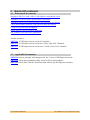
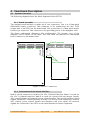
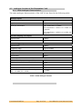
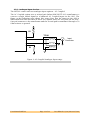
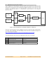
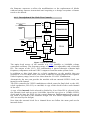
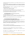
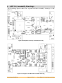
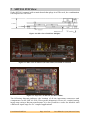
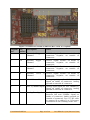
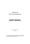
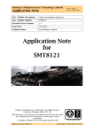
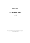
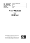
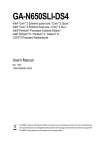
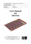
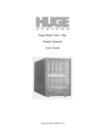
Sundance Multiprocessor Technology Limited
User Manual
Form : QCF42
Date : 11 February 2009
Unit / Module Description:
Dual 1GHz, 8-bit Digitizer (3U PXI Express)
Unit / Module Number:
SMT791
Document Issue Number:
1.1
Issue Date:
11st October 2010
Original Author:
Emmanuel Puillet
User Manual
for
SMT791
Sundance Multiprocessor Technology Ltd, Chiltern House,
Waterside, Chesham, Bucks. HP5 1PS.
This document is the property of Sundance and may not be copied
nor communicated to a third party without prior written
permission.
© Sundance Multiprocessor Technology Limited 2009
User Manual SMT791
Last Edited: 12/10/2010 09:52:00
Revision History
Issue
Changes Made
Date
Initials
1.0
Initial release
11/10/2010
EP
1.1
Review
11/10/2010
SM
Minor corrections, replaced SMT7002 by
SMT6002, updated clock tree diagram.
12/10/2010
E.P
1.1.1
User Manual SMT791
Page 2 of 2
Last Edited: 12/10/2010 09:52:00
Table of Contents
1 Introduction ................................................................................................................... 5 2 Related Documents....................................................................................................... 6 2.1 Referenced Documents .............................................................................................. 6 2.2 Applicable Documents ............................................................................................... 6 3 Acronyms, Abbreviations and Definitions ............................................................. 7 3.1 4 Acronyms and Abbreviations ................................................................................... 7 Functional Description ................................................................................................ 8 4.1 System Overview ......................................................................................................... 8 4.1.1 Board Assembly ...................................................................................................... 8 4.1.2 Presentation of the boards interface .................................................................. 8 4.1.3 System Description ................................................................................................ 9 4.2 Analogue Section of the Mezzanine Card ............................................................ 10 4.2.1 Main Analogue Characteristics .......................................................................... 10 4.2.2 Analogue Input Section ....................................................................................... 11 4.3 Digital Data Stream Description ............................................................................ 12 4.4 Controls Description ................................................................................................ 13 4.4.1 ADC Controls ........................................................................................................ 13 4.4.2 Description of the Clock Tree Controls ........................................................... 14 4.4.3 Triggers Control ................................................................................................... 15 4.4.4 Description of the Power Supply Controls ...................................................... 15 5 Footprint .......................................................................................................................16 5.1 Top View ..................................................................................................................... 16 5.2 Bottom View ............................................................................................................... 16 6 SMT391 Assembly Drawings ................................................................................... 17 7 SMT391 PCB View ....................................................................................................... 18 7.1 Location of SMT391 Test Points ............................................................................ 21 8 Power Supply ............................................................................................................... 21 9 Technical Support ....................................................................................................... 22 10 Support Packages ........................................................................................................ 22 11 Physical Properties ..................................................................................................... 22 12 Safety ............................................................................................................................. 23 13 EMC ................................................................................................................................ 23 User Manual SMT791
Page 3 of 3
Last Edited: 12/10/2010 09:52:00
Table of Figures
Figure 1: SMT391 Connectors ................................................................................................. 8 Figure 2: AC-Coupled Analogue Input stage. ..................................................................... 11 Figure 3: FPGA Data path for one Channel, Channel I or Channel Q. ........................... 12 Figure 4: ADC Data Output. ................................................................................................... 12 Figure 5: Clock tree controls ................................................................................................. 14 Figure 6: Top view of SMT391............................................................................................... 16 Figure 7: Bottom view of SMT391 ........................................................................................ 16 Figure 8: Daughter-card Top Assembly Drawing .............................................................. 17 Figure 9: Daughter-card Bottom Assembly Drawing ........................................................ 17 Figure 10: Side view of SMT391 (Height). ........................................................................... 18 Figure 11: Side view of SMT391 (No Heat Sinks) mounted on a board. ........................ 18 Figure 12: Top view of SMT391 (No Heat Sinks). .............................................................. 18 Figure 13: Connector Location on SMT391 (Rev 2 PCB, AC Coupled). .......................... 19 Figure 14: Voltage Test Point Locations.............................................................................. 21 Figure 15: SMT391 Power Supply Voltages. ....................................................................... 21 Figure 16: Internal Power Supply Voltages. ........................................................................ 22 User Manual SMT791
Page 4 of 4
Last Edited: 12/10/2010 09:52:00
1 Introduction
The SMT791 is a 3U PXI Express digitizer board capable of sampling two analogue
inputs at 1GSPS with a resolution of 8 bits. An e2v/ATMEL dual channel ADC
(AT84AD001) device performs the analogue-to-digital conversion.
This digitizer board features several external I/O interfaces too.
The main features of the SMT791 are:
•
Two ADC channel inputs (ideal for I and Q channel applications),
•
1GHz sampling frequency,
•
8-bit data resolution,
•
Custom clock and trigger inputs via external SMA connectors on the frontpanel,
•
PCI Express transfer to the Host PC at 400Mbytes/s,
•
On-board Flash memory to store the module configuration/application,
•
Xilinx FPGA JTAG header.
More on-board features are available like:
•
One 64-bit wide data bank of DDR2 memory: the bank uses four 16-bit wide
devices. Running this memory at 175MHz provides a maximum access speed
of over 2.8Gbytes/s.
•
Fibre optic modules: Two FPGA serial interfaces are presented here using
Stratos Lightwave 568-LTK-LT12-H modules. These interfaces support
2.5Gbits/s operation,
•
RSL connector: for data streaming to external Hardware,
•
SATA connectors: two FPGA serial interfaces are used (support SATA I/II),
•
A single RJ45 connector provides a 10/100/1000 Ethernet interface. The
RJ45 connects directly to a Marvell 88E1116 PHY, which is interfaced to the
FPGA.
•
Two SHB connectors: for LVTTL GPIOs or data streaming to external device,
•
Four RS232 (accessible from the Xilinx Spartan-3 FPGA or the USB controller),
•
Reset push-button (to re-initialise the carrier board).
User Manual SMT791
Page 5 of 5
Last Edited: 12/10/2010 09:52:00
2 Related Documents
2.1 Referenced Documents
Sundance SMT391 dual 1GHz, 8-bit digitizer mezzanine card
Sundance Local Bus (SLB) specification document
Sundance Rocket-IO Serial Link (RSL) specification document
Texas Instruments Module (TIM) specification document
Comport specification document
Xilinx Virtex-5 FPGA resource manuals
e2v/ATMEL Dual 8-bit ADC datasheet
Similar products:
SMT700: 3U PXI Express board with I/O facilities
SMT702: 3U PXI Express board with two 3GHz, 8-bit ADC channels
SMT712: 3U PXI Express board with two 2.3GHz, 12-bit DAC channels
2.2 Applicable Documents
SMT6300: Driver package with support for the 7-Serie of PXI Express boards
SMT6002: Flash programming utility tool for FPGA-only modules
SMT7026: Host-side software functions and API for the PXI Express interface
User Manual SMT791
Last Edited: 12/10/2010 09:52:00
3 Acronyms, Abbreviations and Definitions
3.1 Acronyms and Abbreviations
FPGA
JTAG
RSL
SLB
Field Programmable Gate Array
Joint Test Action Group
Rocket-IO Serial Link
Sundance Local Bus
User Manual SMT791
Last Edited: 12/10/2010 09:52:00
4 Functional Description
4.1 System Overview
The following diagram shows the block diagram of the SMT791.
4.1.1 Board Assembly
The daughter-card interface is made up of two connectors. One is a 0.5mm pitch
differential Samtec connector. This connector is for transferring the ADC LVDS
output data to the FPGA on the main board. The second one is a 1mm pitch Samtec
header type connector. This connector is for providing power to the daughter-card.
The figure underneath illustrates this configuration. The bottom view of the
daughter card is shown on the right. This view must the mirrored to understand
how it connects to the main board.
Data Connectors
Bank A
Bank B
BankC
Power Connectors
Figure 1: SMT391 Connectors
4.1.2 Presentation of the boards interface
Bank A on the connector is used for the ADC I Channel data bus. Bank C is used for
the ADC Q channel data bus. Bank B is used for system clock and trigger signals,
ADC control signals and general system control signals. The general system control
signals include: PLL control interface (for the VCO circuit), clock synthesizer control,
ADC control, power control signals and daughter card reset signal. All reserved
signals are connected to the FPGA on the main module for future expansion.
User Manual SMT791
Page 8 of 8
Last Edited: 12/10/2010 09:52:00
4.1.3 System Description
The SMT791 refers to the combination of the SMT700 and the SMT391 modules.
Analogue data enters the module via two MMBX connectors – one for each channel.
These two analogue data streams are pre-conditioned before they enter the Atmel
dual channel ADC converter. In conjunction to the two analogue inputs the user can
also provide an external clock and trigger. These two inputs must be LVPECL type
signals.
A single ended version can be built upon request.
All digital functions on the module are controlled by the Xilinx FPGA.
The digital output of the ADC converter is fed into the FPGA. This data is then
stored in FIFOs but can be stored in onboard DDR2 SDRAM for non real-time
processing and then it’s transferred onto the host memory via the PCIe bus.
The FPGA is configured at power-up from the onboard flash. The configuration
process is controlled by a CPLD.
Once the FPGA is configured, the PCIe is used for setting up the SMT391 clock
synthesiser frequency via the FPGA.
The FPGA contains default hard coded values to setup the rest of the mezzanine
components.
User Manual SMT791
Page 9 of 9
Last Edited: 12/10/2010 09:52:00
4.2 Analogue Section of the Mezzanine Card
4.2.1 Main Analogue Characteristics
The main analogue characteristics of the SMT391 are listed in the following table:
Analogue inputs
Input voltage range
0.5Vp-p
Impedance
50Ω - terminated to ground
Analogue Bandwidth
ADC Bandwidth: 1500MHz
RF Transformer: 500kHz to 1.5GHz (AC
Coupled)
RF Transformer: 500kHz to 1.0GHz (DC
Coupled)
External sampling clock inputs
Signal format
LVPECL
Frequency range
Up to 1000 MHz
External trigger inputs
Signal format
LVPECL
Frequency range
Up to 250 MHz
SMT391 Output
Output Data Width
8-Bits
Data Format
Binary
ADC Performance @ FS = 1 GSPS, FIN = 500 MHz (from Atmel datasheet)
Spurious Free Dynamic Range (SFDR)
-57dBc
Signal to Noise and Distortion (SINAD)
45dB
Effective Number Of Bits (ENOB)
7.1 Bits
Total Harmonic Distortion (THD)
-55dB
Cross-talk channel I versus channel Q (Cr)
FIN = 250 MHz, FS = 1 GHz
< -65dBc
Table 1: Main analogue features
User Manual SMT791
Page 10 of 10
Last Edited: 12/10/2010 09:52:00
4.2.2 Analogue Input Section
The SMT391 comes with two analogue input options – AC Coupled.
The AC Coupled option uses a twisted pair balun (MACOM TP-101) transformer to
convert a single ended signal to a balanced AC Coupled input on the ADC. The
figure on the following page shows this setup. Note that the input on the ADC is
differential and that for each of these two signals there are two pads on the ADC.
One pad connects to the transformer and the second pad is terminated through a 50
Ohm resistor to ground.
R1
TP101
Input
Connector
R1
Figure 2: AC-Coupled Analogue Input stage.
User Manual SMT791
Page 11 of 11
Last Edited: 12/10/2010 09:52:00
4.3 Digital Data Stream Description
The data-path for both channels on the mezzanine and in the FPGA is identical. The
ADC is driven by a clock either generated on the mezzanine (one clock for both
channels) or provided by the user through MMBX connectors (one clock for each
channel). The following figure is a diagrammatic representation of the data-path
inside the FPGA.
ADC
Channel Data A
Input
delay
calibration
unit
DDR Data
Recapture
Fifo
ADC
Channel Data B
Input
delay
calibration
unit
XLINK for Channel
DDR Data
Recapture
Figure 3: FPGA Data path for one Channel, Channel I or Channel Q.
The ADC sends an image of the sampling clock (Fs/4) with the data in DDR mode,
on both I and Q channels. The data timing versus the clock is detailed in figure 4.2
p.12 of the ADC User Guide:
http://www.atmel.com/dyn/resources/prod_documents/doc2153.pdf)
The following table shows how the output data of the ADC is encoded:
Description
Binary Value (8 Bits)
1
Positive full scale is 255
"11111111"
2
Bipolar zero +1/2 LSB is 128
"10000000"
3
Bipolar zero -1/2 LSB is
"01111111"
4
Negative full scale is 0
"00000000"
Figure 4: ADC Data Output.
User Manual SMT791
Page 12 of 12
Last Edited: 12/10/2010 09:52:00
PCIe
Interface
4.4 Controls Description
The control information is used to configure various components on the SMT391.
The ADC, clock generators and clock multiplexors are setup from the FPGA.
The FPGA is used to give default behaviour to the mezzanine so as to run the demo
from power-up.
For the demo to run, the mezzanine is setup as follows:
•
•
•
The clock synthesiser is selected as the clock source for the ADC sampling
clock (Fs) on both channels.
The clock synthesiser receives an output frequency value and configures
itself to generate a clock at that speed.
The ADC auto-calibrates once the sampling clock is stable in input.
It is recommended to use the PLL+VCO for high frequencies generation and to use
the clock synthesiser for lower frequency generation or for test purposes.
The Firmware package provided supports all clock setups with “VHDL” and “C”
functions, whether the configuration happens only once at power up from the FPGA
or whether the clocks need to have their values changed during runtime, in which
case it can be done from the host.
Likewise, the ADC setup functions are provided both in “VHDL” and in “C”.
The control interfaces for the ADC and clock components are 3 wire serial
interfaces, all managed by the FPGA code.
4.4.1 ADC Controls
The FPGA set ups the ADC to provide the data to the FPGA according to the timing
diagram in figure 4.2 p.12 of the ADC User Guide:
http://www.atmel.com/dyn/resources/prod_documents/doc2153.pdf)
The other settings are left to default and can be changed if required.
The files used to set up the control words in the FPGA firmware are:
- adc_setup.vhd and adc_setup_pkg.vhd.
A software routine is also provided if the set up is to be managed by a host
application to allow more flexibility.
The ADC input clock determines the sampling rate of the ADC. The ADC buffers and
divides this clock by two or four (in the set up mentioned above) to provide an LVDS
clock for each of the de-multiplexed data channel. These two clocks are used to
clock the ADC data into the FPGA.
The ADC can be set up to provide data in a different manner than the one used in
the demo firmware. The firmware would need some modifications but we designed
User Manual SMT791
Page 13 of 13
Last Edited: 12/10/2010 09:52:00
the firmware structure to allow the modifications or the replacement of blocks
without having features intertwined and requiring a re-design everytime a feature
needs to be altered.
4.4.2 Description of the Clock Tree Controls
Multiplexer
External Clock Channel I
0
S1
1
S2
External Clock Channel Q
Channel I clk
D
En
Rst
C
ENB
AT84AD001B
adcI_pins_clksrc
Multiplexer
CLKSYNTH
VCO
S1
1
S2
S1
1
S2
Channel Q clk
D
C
ENB
Rst
En
Multiplexer
0
0
D
adcQ_pins_clksrc
C
En
ENB
Rst
FPGA
Clk Div 8
clksrc_pins_sel
CLKSRCMUXRST
nEn
Rst
div8_pins_nEn
div8_pins_reset
Figure 5: Clock tree controls
The main clock source of the module is a UMC 600MHz to 1000MHz voltage
controlled oscillator. The frequency range of the VCO is adjustable with a National
PLL. The output of the VCO + PLL combination is passed through a Maxim high
frequency comparator with an LVPECL output to form the main system clock.
In addition to this clock there is a clock synthesizer on the module that can
generate a 50 to 950 MHz clock. This clock is ideal for testing purposes as it spans a
wider frequency range, but it is less clean than the VCO+PLL combination.
Alternatively the user can provide the module with an external LVPECL clock, one
input for each channel.
The FPGA controls the LVPECL multiplexers which route the final clock to the ADC
(clock synthesizer, PLL+VCO, or external). A copy of this clock is fed to each channel
of the ADC.
A copy of the internal clock selected is divided by 8 (so if the PLL is selected to be
the internal clock and set up at 1000 MHz, then the copy gives a 125MHz LVPECL
clock) and fed into the FPGA. (In the current firmware implementation this copy of
the clock is not used by the firmware design. The two clocks originating from the
ADC are used by the design).
Note that the external clock for a channel does not follow the same path as the
internal clocks.
User Manual SMT791
Page 14 of 14
Last Edited: 12/10/2010 09:52:00
An image of the external clock divided by 8 is not available in the FPGA, like it is for
the internal clock.
All clock circuitry is implemented on the daughter card. The four clocks that enter
the FPGA are passed down from the daughter card to the main board. Additional
clocks are present on the main board and can be used to clock different parts of the
design.
The control signals names in Figure 5 correspond to the names in the firmware
implementing the demo.
The sources that select the clock source path used are:
- SelClkrsrc.vhd and SelClkrsrc_pkg.vhd.
The clock sources setups can be managed by the host of from the FPGA directly.
Both vhdl and software routines are provided to allow more flexibility.
In the default firmware implemented for the demo, the clock synthesiser is set up
by the host and the VCO/PLL is set up by the FPGA.
4.4.3 Triggers Control
One trigger is available per ADC channel.
The external trigger input is received on a MMBX, fed into a LVPECL input buffer on
the SMT391. The buffered signal is passed down as a differential LVPECL signal to
the FPGA.
The Current firmware implementation does not use the external triggers.
4.4.4 Description of the Power Supply Controls
The 3.3V, 5.0V, +12V and -12V present on the main board are passed to the
daughter card (SMT391) over the daughter card power connector.
On the daughter card the ADC requires digital 3.3V, analog 3.3V and digital 2.25V.
The 3.3V from the main board to daughter card power connector is used for the
digital 3.3V. This voltage is filtered to provide the analog 3.3V. The 2.25V is
generated by a TI low noise low dropout regulator.
The PLL + VCO require +12V, -12V and +5V.
You need to make sure that the main board’s power supply tree is setup by using
the right switch settings on the main board to provide these voltages.
The FPGA also has two pins enabling the DC/DC converters of the SMT391.
These pins are set by the FPGA once it configured and are controlling two power
switch devices on the mezzanine.
The Digital 3.3v is controlled by switch “U18” enabled with the signal
“ps3v3_pins_en” from the FPGA pin AM12".
The 2.25v regulator “U16” is enabled by signal “ps2v5_pins_en” pin “AM11”.
User Manual SMT791
Page 15 of 15
Last Edited: 12/10/2010 09:52:00
5 Footprint
5.1
Top View
Figure 6: Top view of SMT391
5.2 Bottom View
Figure 7: Bottom view of SMT391
User Manual SMT791
Page 16 of 16
Last Edited: 12/10/2010 09:52:00
6 SMT391 Assembly Drawings
The following figures show the top and bottom assembly drawings of the
SMT391.
Figure 8: Daughter-card Top Assembly Drawing
Figure 9: Daughter-card Bottom Assembly Drawing
User Manual SMT791
Page 17 of 17
Last Edited: 12/10/2010 09:52:00
7 SMT391 PCB View
If the SMT391 is mated with a main board that plugs in a PXIe rack, the combination
will require two PXI slots.
Figure 10: Side view of SMT391 (Height).
Figure 11: Side view of SMT391 (No Heat Sinks) mounted on a board.
Figure 12: Top view of SMT391 (No Heat Sinks).
The following diagram indicates the location of all the important connectors and
components on the SMT391 PCB. This specific diagram is for an AC coupled analog
input stage using a Macom transformer. It is also possible to order the module with
a different input stage for DC coupled applications.
User Manual SMT791
Page 18 of 18
Last Edited: 12/10/2010 09:52:00
Figure 13: Connector Location on SMT391 (Rev 2 PCB, AC Coupled).
Diagram Pcb
Description
Ref
RefDes
Notes
A
J9
External
Channel
Trigger
I LVPECL Signal. Positive on inside of
connector. Negative on outside of
connector.
E
J10
External
Channel
Trigger
Q LVPECL Signal. Positive on inside of
connector. Negative on outside of
connector.
B
J3
External
Channel
Clock
I LVPECL Signal. Positive on inside of
connector. Negative on outside of
connector.
F
J4
External
Channel
Clock
Q LVPECL Signal. Positive on inside of
connector. Negative on outside of
connector.
C
J1
ADC I Channel Input
Analog signal input for ADC Channel I.
Signal on inside of connector. Analog
ground on outside of connector.
G
J2
ADC Q Channel Input
Analog signal input for ADC Channel Q.
Signal on inside of connector. Analog
ground on outside of connector.
D
J8
Analog Test Signal
Analog output test signal. Variable
between 200 and 350MHz. Signal on
inside of connector, Analog ground on
outside of connector. Use a 1:1 RF cable
to connect J8 to either J1 or J2 for easy
verification of the working of the ADC.
Table 2: Table of Connector Locations on SMT391.
User Manual SMT791
Page 19 of 19
Last Edited: 12/10/2010 09:52:00
Diagram Pcb
Ref
RefDes
Description
Notes
H
JP2
FPGA
Connector
K
JP1
MSP JTAG Connector
N/A
L
U1
Atmel Dual ADC
ADC Requires heat-sink with air-flow
cooling in a system setup
I
VCO1
UMC 600 – 1000MHz Main Clock source for SMT391. VCO
VCO
Requires heat-sink with air-flow cooling
in a system setup.
I
VCO2
UMC 200 – 350MHz Test Clock for testing the analog input
VCO
of the ADC. VCO Requires heat-sink
with air-flow cooling in a system setup.
J
TRANS1 M/A
Com
Transformer
TP101 By default the SMT391 analog input is
AC coupled through a twisted pair
balum transformer (single ended to
differential). It is possible to order the
SMT391 with a DC coupled input using
a 1:1 balum transformer (circuit also
wired as single ended input on
connector side to differential input on
ADC side). Refer to section 2.11 for
more details.
J
TRANS2 M/A
Com
Transformer
TP101 By default the SMT391 analog input is
AC coupled through a twisted pair
balum transformer (single ended to
differential). It is possible to order the
SMT391 with a DC coupled input using
a 1:1 balum transformer (circuit also
wired as single ended input on
connector side to differential input on
ADC side). Refer to section 2.11 for
more details.
JTAG FPGA on main board JTAG Chain. Use
for easy access without having to
remove the SMT391.
Table 3: Table of Component Locations on SMT391.
User Manual SMT791
Page 20 of 20
Last Edited: 12/10/2010 09:52:00
7.1 Location of SMT391 Test Points
The following figure shows the location of the voltage test points on the SMT391.
Figure 14: Voltage Test Point Locations.
8 Power Supply
The following voltages are required by the SMT391 and must be supplied over the
daughter card power connector.
Voltage
Current
Required
D+3V3_IN
2.0 A
D+5V0_IN
500 mA
D+12V0_IN
250 mA
D-12V0_IN
250 mA
DGND
Figure 15: SMT391 Power Supply Voltages.
The following table lists the internal SMT391 voltages that are derived from the
voltages that are provided over the daughter card power connector.
Voltage
Description
D+3V3
Derived from D+3V3_IN
D+2V25
Derived
SMT391
User Manual SMT791
Page 21 of 21
from
D+3V3
on
Last Edited: 12/10/2010 09:52:00
A+3V3
Derived from D+3V3_IN
VCO+5V0
Derived from D+5V0_IN
VCO+12V0
Derived from D+12V0_IN
ECL-5V2
Derived from D-12V0_IN
AGND
Derived from DGND
Figure 16: Internal Power Supply Voltages.
9 Technical Support
Contact Sundance’s technical support.
10 Support Packages
The SMT791 is supported by a firmware package with software and VHDL routines
enabling the user to customise or use “as is” the system.
The Host software must be developed using the SMT7026.
The demo GUI provides an easy-to-use interface to validate the system, but it is
recommended to customise it and/or to develop your own host and firmware to
meet your requirements.
All sources are provided to help you with your development.
The following board support packages are mandatory to use the SMT791:
•
SMT6300: Driver package with support for the SMT700 carrier board,
•
SMT6002: Flash programming utility tool for FPGA-only modules.
11 Physical Properties
Dimensions
63.5mm
Weight
TBD.
106.68mm
Supply Voltages
Supply Current
+12V
TBD
+5V
TBD
+3.3V
TBD
-5V
TBD
-12V
TBD
MTBF
It is recommended to use cooling fans, or other efficient cooling system.
User Manual SMT791
Page 22 of 22
Last Edited: 12/10/2010 09:52:00
12 Safety
This module presents no hazard to the user when in normal use.
13 EMC
This module is designed to operate from within an enclosed host system, which is
build to provide EMC shielding. Operation within the EU EMC guidelines is not
guaranteed unless it is installed within an adequate host system.
This module is protected from damage by fast voltage transients originating from
outside the host system which may be introduced through the output cables.
Short circuiting any output to ground does not cause the host PC system to lock up
or reboot.
User Manual SMT791
Page 23 of 23
Last Edited: 12/10/2010 09:52:00