1
ICE MACHINE
SERVICE MANUAL
Manitowoc Beverage Equipment
2100 Future Drive Sellersburg, IN 47172-1868
Tel: 812.246.7000, 800.367.4233 Fax: 812.246.9922
www.manitowocbeverage.com
In accordance with our policy of continuous product development and
improvement, this information is subject to change at any time without notice.
5005979 07-20-07 REV 0
Installation and Service Manual
FOREWORD
Manitowoc Beverage Equipment (MBE) developed this manual as a reference guide for the owner/
operator, service agent, and installer of this equipment. Please read this manual before installation
or operation of the machine. A qualified service technician should perform installation and startup of this equipment, consult the Troubleshooting Guide within this manual for service assistance.
If you cannot correct the service problem, call your MBE Service Agent or Distributor. Always have your model and
serial number available when you call.
Your Service Agent ___________________________________________________________________
Service Agent Telephone Number ______________________________________________________
Your Local MBE Distributor ___________________________________________________________
Distributor Telephone Number _________________________________________________________
Model Number ______________________________________________________________________
Serial Number _______________________________________________________________________
Installation Date _____________________________________________________________________
UNPACKING AND INSPECTION
Note: The unit was thoroughly inspected before leaving the factory. Any damage or irregularities should
be noted at the time of delivery.
WARRANTY INFORMATION
Consult your local MBE Distributor for terms and conditions of your warranty. Your warranty specifically
excludes all beverage valve brixing, general adjustments, cleaning, accessories and related servicing.
Your warranty card must be returned to Manitowoc Beverage Equipment to activate the warranty on this
equipment. If a warranty card is not returned, the warranty period can begin when the equipment leaves
the MBE factory.
No equipment may be returned to Manitowoc Beverage Equipment without a written Return Materials
Authorization (RMA). Equipment returned without an RMA will be refused at MBE’s dock and returned to
the sender at the sender’s expense.
Please contact your local MBE distributor for return procedures.
3
Installation and Service Manual
TABLE OF CONTENTS
FOREWORD ........................................................................................................ 3
UNPACKING AND INSPECTION ......................................................................... 3
WARRANTY INFORMATION ............................................................................... 3
SAFETY ............................................................................................................... 6
IMPORTANT SAFETY INSTRUCTIONS ........................................................................... 6
CARBON DIOXIDE WARNING ......................................................................................... 6
QUALIFIED SERVICE PERSONNEL ................................................................................ 6
SHIPPING, STORAGE, AND RELOCATION ..................................................................... 6
ADDITIONAL WARNINGS ................................................................................................ 6
GROUNDING INSTRUCTIONS ........................................................................................ 7
WARRANTY INFORMATION ............................................................................... 8
SERVEND MODEL NUMBERING SYSTEM ..................................................................... 8
SERVEND INTERNATIONAL SERVICE POLICY AND PROCEDURE .............................. 9
INSTALLATION .................................................................................................. 10
ICE MACHINE INSTALLATION INSTRUCTIONS ........................................................... 10
SIPHON VENT ................................................................................................................. 11
DUMP VALVE ................................................................................................................. 12
ADJUSTING PROPER WATER LEVEL .......................................................................... 15
WATER CURTAIN ADJUSTMENT .................................................................................. 18
STACKING KITS ............................................................................................................. 19
ICE MAKER CLEANING PROCEDURE ......................................................................... 20
REMOTE CONDENSER INSTALLATION INSTRUCTIONS ............................................ 21
REMOTE CONDENSER INSTALLATION GUIDELINES ................................... 22
REMOTE CONDENSERS MAXIMUM LOCATION DISTANCE ....................................... 22
COMPONENT DIAGNOSTICS .......................................................................... 23
DECISION TREE BEFORE REPLACING A THERMISTOR ............................................ 25
DIAGNOSIS OF SERVEND CUBER THERMISTOR ....................................................... 26
FLOWCHART ................................................................................................................. 27
SAFETY THERMO-DISC / FAN CYCLE CONTROL ....................................................... 29
HEAD PRESSURE CONTROL VALVE ........................................................................... 30
HOT GAS VALVE / COMPRESSOR CONTACTOR / CHECK PROCEDURE .................. 31
COMPRESSOR AND STARTING COMPONENTS CHECK OUT PROCEDURE ............ 32
TOTAL ICE CAPACITY / ICE PRODUCTION CHECK ..................................................... 33
4
Installation and Service Manual
TABLE OF CONTENTS
3 RELAY CIRCUIT BOARD SEQUENCE OF OPERATION /
ADJUSTING BRIDGE THICKNESS / 3 RELAY CIRCUIT BOARD .................................. 36
3 RELAY CIRCUIT BOARD PROXIMITY SWITCH CHECK PROCEDURE ..................... 37
PROXIMITY SWITCH VOLTAGE CHECK ....................................................................... 38
4 RELAY CIRCUIT BOARD SEQUENCE OF OPERATION ............................................ 39
ADJUSTING BRIDGE THICKNESS ................................................................................ 42
HALL SWITCH CHECK PROCEDURE 4 RELAY CIRCUIT BOARD ............................... 43
TROUBLESHOOTING ....................................................................................... 44
PROBLEM ANALYSIS GUIDE - 3 RELAY BOARD ......................................................... 44
EVACUATION AND CHARGING ....................................................................... 50
SYSTEM EVACUATION AND CHARGING / ALL REMOTE SYSTEMS DISCHARGE,
EVACUATION & RECHARGING PROCEDURES ........................................................... 50
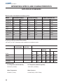
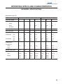
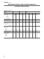
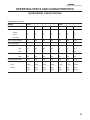
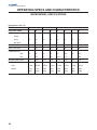
OPERATING SPECS AND CHARACTERISTICS.............................................. 52
DATA PER ARI STANDARDS ......................................................................................... 52
AIR MODEL SPECIFICATIONS ...................................................................................... 53
WATER MODEL SPECIFICATIONS ................................................................................ 55
REMOTE MODEL SPECIFICATIONS ............................................................................. 57
COMPRESSOR SPECIFICATIONS ................................................................................ 58
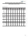
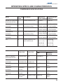
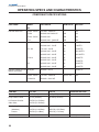
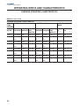
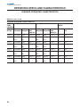
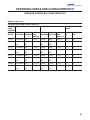
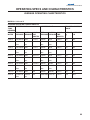
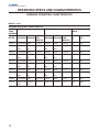
AVERAGE OPERATING CHARCTERISTICS ................................................................. 61
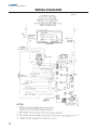
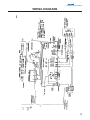
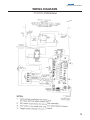
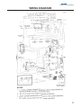
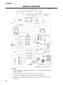
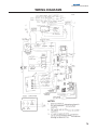
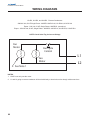
WIRING DIAGRAMS .......................................................................................... 71
INDEX................................................................................................................. 83
5
Installation and Service Manual
SAFETY
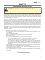
IMPORTANT SAFETY INSTRUCTIONS
Carefully read all safety messages in this manual. Learn how to operate the SV unit properly. Do
not allow anyone to operate the unit without proper training and keep it in proper working condition. Unauthorized modifications to the SV may impair function and/or safety and affect the life of
the unit.
CARBON DIOXIDE WARNING
DANGER: Carbon Dioxide (CO2) displaces oxygen. Exposure to a high concentration of CO2 gas
causes tremors, which are followed rapidly by loss of consciousness and suffocation. If a CO2 gas leak
is suspected, particularly in a small area, immediately ventilate the area before repairing the leak. CO2
lines and pumps should not be installed in an enclosed space. An enclosed space can be a cooler or
small room or closet. This may include convenience stores with glass door self serve coolers. If you
suspect CO2 may build up in an area, venting of the B-I-B pumps and / or CO2 monitors should be utilized.
QUALIFIED SERVICE PERSONNEL
WARNING: Only trained and certified electrical and plumbing technicians should service this unit.
All wiring and plumbing must conform to national and local codes.
SHIPPING, STORAGE, AND RELOCATION
CAUTION: Before shipping, storing, or relocating this unit, syrup systems must be sanitized. After
sanitizing, all liquids (sanitizing solution and water) must be purged from the unit. A freezing environment causes residual sanitizing solution or water remaining inside the unit to freeze, resulting
in damage to internal components.
ADDITIONAL WARNINGS
Installation and start-up of this equipment should be done by a qualified service technician. Operation,
maintenance, and cleaning information in this manual are provided for the user/operator of the equipment.
Save these instructions.
6
Installation and Service Manual
SAFETY
GROUNDING INSTRUCTIONS
WARNING: Risk of electrical shock. Connect to a properly grounded outlet only.
This appliance must be grounded. In the event of malfunction or breakdown, grounding provides
a path of least resistance for electric current to reduce the risk of electric shock. This appliance is
equipped with a cord having an equipment-grounding conductor and a grounding plug. The plug
must be plugged into an appropriate outlet that is properly installed and grounded in accordance
with all local codes and ordinances.
DANGER – Improper connection of the equipment-grounding conductor can result in a risk of
electric shock. The conductor with insulation having an outer surface that is green with or without
yellow stripes is the equipment grounding conductor. If repair or replacement of the cord or plug
is necessary, do not connect the equipment-grounding conductor to a live terminal. Check with a
qualified electrician or serviceman if the grounding instructions are not completely understood, or
if in doubt as to whether the appliance is properly grounded. Do not modify the plug provided with
the appliance – if it will not fit the outlet, have a proper outlet installed by a qualified electrician.
WARNING – When using electric appliances, basic precautions should always be followed, including the following:
a) Read all the instructions before using the appliance.
b) To reduce he risk of injury, close supervision is necessary when an appliance is used
near children.
c) Do not contact moving parts.
d) Only use attachments recommended or sold by the manufacturer.
e) Do not use outdoors.
f) For a cord-connected appliance, the following shall be included:
• Do not unplug by pulling on cord. To unplug, grasp the plug, not the cord.
• Unplug from outlet when not in use and before servicing or cleaning.
• Do not operate any appliance with a damaged cord or plug, or after the appliance
malfunctions or is dropped or damaged in any manner. Return appliance to the
nearest authorized service facility for examination, repair, or electrical or mechanical
adjustment.
g) For a permanently connected appliance – Turn the power switch to the off position when
the appliance is not in use and before servicing or cleaning.
h) For an appliance with a replaceable lamp – always unplug before replacing the lamp.
Replace the bulb with the same type.
i) For a grounded appliance – Connect to a properly grounded outlet only. See Grounding
Instructions.
SAVE THESE INSTRUCTIONS
7
Installation and Service Manual
WARRANTY INFORMATION
SERVEND MODEL NUMBERING SYSTEM
Example:
MODEL- C
(1)
7 (2)
A
(3)
M
(4)
A
(5)
S (6)
A
(7)
A
(8)
(1) Series of the machine
C = 30" or 48" wide cuber
S = 22" wide cuber
B = Ice Storage Bin
(2) Nominal Capacity per twenty four hours in one hundred pounds
I.E. 7 = Seven Hundred Pounds
(3) Type of Condenser
A = Air Cooled
W = Water Cooled
R = Remote Cooled
(4) Size of Cube
M = Mini Cube (3/8" x 7/8" x 7/8")
F = Full Cube (7/8" x 7/8" x 7/8")
J = Jumbo Cube (7/8" x 7/8" x 1 1/2")
(5) Electric Code
Volts
A = 208/230; 200
B = 115
C = 208/230; 200
D = 220/240
F = 208/230
G = 208/230
H = 220/240
(6)
Cycle
60; 50
60
60; 50
50
60
60
50
Phase
1
1
1
1
1
3
3
S = Stainless Steel Panels
(Blank) = Painted Panels
P = Painted Panels
(7) Generation Code
A, B, C, etc.....
(8) Unit Configuration
A = Standard Machine
Any Other Letter = Special Machine, call factory for parts or service information.
8
Installation and Service Manual
WARRANTY INFORMATION
SERVEND INTERNATIONAL SERVICE POLICY AND PROCEDURE
DATE ISSUED: AUGUST 12, 1991
DATE EFFECTIVE: AUGUST 12, 1991
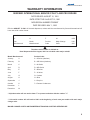
NEW SERIAL NUMBER FORMAT
DATE REVISED: MAY 1, 1993
Effective AUGUST 12.1991 all Servend dispensers, cubers and bins manufactured by Servend International will
have new serial number format.
SAMPLE:
91
H
F
01
0001
Year
Month
Product
Major Change
Unit
Manufactured
Manufactured
Code
Code
S/N
The above serial number is defined as:
Hotel dispenser built in August, 1991 1st unit built under major code #1
Month Manufactured:
Product Code:
January
A
A = K Series (obsolete)
February
B
B = KD Series (obsolete)
March
C
C = M Series
April
D
D = MD Series
May
E
E = B Series
June
F
F = H Series
July
G
G = Cubers
August
H
H = Bins
September
J
J = Drop-ins
October
K
7 = Remote Condensers
November
L
December
M
** Alphabet codes will not use the letter "I" to prevent confusion with the number "1".
** Unit serial number will roll back to 0001 at the beginning of each new year and/or with each major
change code.
MAJOR CHANGE CODE IS AN ENGINEERING TRACKING CODE FOR SERVEND USE.
9
Installation and Service Manual
INSTALLATION
ICE MACHINE INSTALLATION INSTRUCTIONS
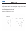
Freight Claim Loss or Damage:
1. The delivery freight company, distributor or
dealer is responsible for loss or damage to your merchandise. All claims must be filed with the party that delivers your merchandise.
2. Check the number of containers delivered
against the number shown on your receipt. If the total is
not correct, have the driver note the shortage on your
receipt.
3. Check all cartons for visible damage, open and
check the contents of any carton in question before the
driver leaves. Be sure the driver notes the type and degree fo damage on your receipt. All damaged merchandise must be inspected within 15 days of delivery, notify
your carrier immediately.
4. If concealed damage is found when merchandise in unpacked, place the packing material with the
merchandise and request an inspection from the delivering carrier.
5. File your claims for loss or damage at once.
Delays in filing will only hinder achieving a satisfactory
resolution to your claim.
Your ice maker will perform at optimum efficiency in
a approximate 70oF (21.1oC) room with 50oF (10oC) water. Increased air or water temperatures will decrease
performance. Never operate your machine in rooms with
temperatures below 50oF (10oC) or above 100oF (38oC).
If the ice maker is located in an unheated area, it
must be protected from freezing temperatures or shut
down and winterized.
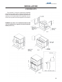
Set-up of the Storage Bin and Cuber:
1. Remove the bin from the shipping carton. Using
the carton for protection against scratching, place the
bin on its back.
2. Screw the bin legs (enclosed inside the bin) into
the bottom of the ice bin.
3. Place the bin upright in the permanent position.
4. Remove the carton from the ice maker and place
the ice maker on the bin. Align the ice maker with the bin
back. Install stabilizing bolts through the lower front channel of the ice maker and into the header plate of the bin.
These bolts are packed in the plastic bag located in the
water pan of the ice maker.
We recommend that installation and start-up be performed by the Dealer Professionals where your ice maker
was purchased.
5. Remove the ice maker internal packing. Level
the ice maker with a torpedo level on the face of the
evaporator. The evaporator MUST be plumb vertically
and level horizontally left to right. Level the machine by
screwing the feet of the bin either up or down.
Location:
Plumbing Lines and Connections:
For best performance, select a location away from
all heat sources, such as radiators, ovens, refrigeration
equipment, direct sunlight, etc.
All plumbing (water and drain) connnections must
conform to local and national codes.
Installation:
Avoid placing air cooled models in kitchens whenever possible as grease, flour or other airborn particles
will collect on the condenser and fan blade, requiring
increased preventative maintenance and will reduce efficiency.
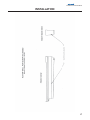
Discuss the best location with your Dealer Professional. Allow a minimum of 6" (15.24cm) clearance
around the ice maker for air circulation (both sides, top,
and black). Restricted air circulation will affect the maintenance-free life or your ice maker and its effeciency.
10
To prevent condensation, insulate all water supply
and drain lines. Insulating water lines will increase efficiency as well.
Installation and Service Manual
INSTALLATION
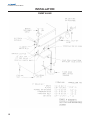
SIPHON VENT
11
Installation and Service Manual
INSTALLATION
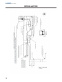
DUMP VALVE
12
Installation and Service Manual
INSTALLATION
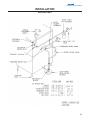
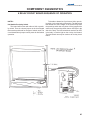
Shut off valves should be loacted in the water supply lines for ice maker and condenser (water cooled
units). The water inlet strainer must be installed in the
ice maker water supply (see diagram on water curtain
and/or rear of machine). Water supply to water cooled
condensers should include a standpipe for the prevention of "water hammer".
It may be necessary to connect water supply to a
water treatment system. Consult your local Servend
Dealer or Distributor for proper size required. Water treatment may pay for itself through reduced maintenance,
higher efficiency, quality of ice, and longer equipment
life.
NOTE: Water cooled units connected to recirculation systems or cooling towers etc., must maintain
a minimum of 10 psi pressure drop across the condenser when operational.
Drains:
To ensure trouble-free drainage, vent cuber and bin
drains to the atmosphere at the cabinet (see sketch).
Drain lines from the cabinet require 1/4" (6mm) drop
per foot (30cm) fo run. Lines should terminate over an
open trapped and vented floor drain.
Electrical:
All supply wiring and connections must conform to
the national and local engineering codes. Size wiring and
fuse per nameplate specification. Connect the cuber to
a seperately fused circuit. Conduit must be connected
to the electrical control box inside the cuber, not the rear
panel on a "C" Series machine. Place a manual disconnect in a convenient location between the cuber and fuse
box. The cuber must be grounded by the control box
ground screw or conduit connection.
Installation Check List:
1. Has cuber evaporator been leveled?
2. Are electrical connections complete per nameplate specifications? Is manual disconnect "ON"?
3. Check water and drain connections:
A) Has water inlet pressure been checked?
B) Are water shut-off valves open?
C) Is water strainer installed?
D) Is bin drain tube assembled to bin?
E) When used, is the water cooled condenser
drained seperately?
F) Are drain lines vented?
G) Are drain lines insulated and sloped to floor
drain?
4. Is there 6" (15.24cm) clearance at cuber sides,
back, top for air circulation?
5. Is the cuber installed where ambient temperatures will not be bleow 50oF (10oC) or above 100oF
(38oC)? Will incoming water temperature be maintained
between 45oF (7oC) and 90oF (32oC)? If air temerature
drops below 50oF (10oC) shut unit down! Disconnect all
water lines to prevent freeze up of unit.
6. Does water curtain move freely?
7. Check float valve and adjust water level as required. Be certain water pan is seated on its support
block.
8. Has storage bin and cuber been sanitized?
Air deflection baffles are available for all air cooled
equipment. The baffles attach to the side and rear to
prevent air from recirculating through the condenser.
Sart-Up Procedure Siphon System:
13
Installation and Service Manual
INSTALLATION
Sart-Up Procedure Siphon System:
1. Place the ON/OFF switch in the water pump
position. Only the water pump will start. Permit the sump
to fill and the float to shut off. Check for continuous and
even water flow over top plastic extrusion and evaporator. Is water flowing from all water distribution tube holes?
Check water level in siphon tube.
2. Place switch in "off" position. Water should fill
the sump and pan tube starting a siphoning action. The
siphon should drain the sump then stop flowing. In not,
lower the water level to approximately 3/8" (.95cm) below the siphon clip.
3. Place switch in the ice position, the compressor,
condenser fan motor (if air cooled) and water pump and
fan motor will stop and the harvest solenoid will open.
Swing the water curtain open and hold for a maximum of
15 seconds, the compressor will stop. Release the water curtain and the compressor, fan motor and water
pump will start, initiating a new ice making cycle.
4. For optimum life performance of the ice maker,
the bridge should be a minimum of 1/8" (.32cm) to a
maximum of 3/16" (.475cm) in the center of the ice sheet.
Permit the ice maker to drop two (2) complete sheets of
ice before making any bridge adjustment.
5. Ice bridge adjustment:
A.If ice size requires adjustment, use fine adjustment only.
Purge Valve System:
1. Open water valve to machine and allow the water pan to fill with water through the float valve. Check
the water level in the water pan - adjust if required to
have water level equal to the crease in the side of the
pan.
2. Engage electric to the machine. Turn the water
pump to the "on" position. Check for continuous and even
water flow over the top plastic extrusion and evaporator.
Is the water flowing from all holes in the distribution tube?
If the water seems to "creek" at the top extrusion without
having a slow sheet fo water cascading over the top extrusion, clean the top extrusion with Scotch Brite pad or
terry cloth.
3. With the toggle switch in the pump postion, check
the dump valve. Depress the manual dump switch and
hold. This should clean out most of the water in the water pan while allowing the float to refill the pan.
14
4. Place the switch in the ice position. The compressor, condenser fan (if air cooled), and water pump
will operate. Depress the manual harvest switch, the
water pump and fan motor will stop and the harvest solenoid will open. Swing the water curtain open and hold
for a maximum of thirty (30) seconds. The compressor
will then stop. Release the water curtain. The water pump
and compressor fan (if air cooled) will start in the ice
making cycle.
5. For optimum life and performance fo the ice
maker, the bridge should be minimum of 1/8" (.32cm) to
a maximum of 3/16" (.475cm) in the center of the ice
sheet. Permit the ice maker to drop two (2) complet
sheets of ice before making any bridge adjustment.
6. To adjust the bridge thickness of the ice sheet,
go to the bottom of the circuit board. There is a bank of
eight (8) DIP switches. To make the bridge thicker, turn
the next switch to the "on" position. To make the bridge
thinner, turn the next switch to the "off" position.
7. If you have any difficulty in the operation of this
machine, please call your local Servend service company or dirstributor.
Owner/Operator:
Before leaving, be sure the owner/operator understands the ice maker operation and the value of preventative maintenance.
Does the owner know:
1. Location of the electrical disconnect switch and
water shut-off valves?
2. How to start, shut down, clean and sanitize?
3. Bin full operation?
4. Proper method of cleaning condenser and fan
blade?
5. To inspect distribution tubes and evaporator for
mineral deposits.
6. How to identify when water filter needs replacing?
7. Who to contact for product information or service? We suggest placing the organization's name and
phone number on the front panel.
8. Use and location of high pressure reset on water cooled equipment?
Installation and Service Manual
INSTALLATION
ADJUSTING PROPER WATER LEVEL
Siphon System:
Dump System:
A) Be sure water pan is properly seated on its support blocks.
A) Adjust float by disengaging the bracket screws
to raise, or lower, float assembly.
B) Adjust float by releasing the bracket screws to
raise, or lower, float assembly.
B) Water level to be set at water level mark on water pan (see diagram).
C) Water level should be set 3/8" (.95cm) below the
bottom of siphon hose clip.
C) With water level set, turn water pump ON to circulate the water. Examine to be sure the float will return
water level to original setting and stops inlet water.
D) With water level set, turn pump on to circulate
the water. Be sure the float will return water level to original setting and stops inlet water.
E) Turn water pump off. The machine should now
siphon, the siphon action stops and the float returns the
water level to original settings.
F) The flow washer in the float assembly (detail A)
will control water pressure from 55/120 PSI (3.79/8.27
Bars) to eliminate float chatter. In low water areas 20
PSI (1.37 Bars) and less, remove the flow washer.
D) Depress and hold the manual dump switch (white
button by toggle switch) - allow dump action to empty
water pan. This is a momentary switch - you must hold it
depressed to complete manual dump cycle.
E) Release the manual dump switch - float should
return water to original level.
15
Installation and Service Manual
INSTALLATION
16
Installation and Service Manual
INSTALLATION
17
Installation and Service Manual
INSTALLATION
WATER CURTAIN ADJUSTMENT
The water curtain acts as a shield to prevent the
water circulated across the evaporator from teh splashing into the bin, resulting in additional make up water
being required.
Adjustment must also observe side to side travel of
curtain. Any side to side movement of 1/16" (.16cm) or
greater must be shimmed out as this would create erratic operation of proximity and/or Hall switch.
To adjust, the screws holding the curtain bracket and
pin assembly must be loosened, left and right side. The
bracket assembly will allow the curtain to be adjusted
5/16" (8mm) up or down and front to rear. the bottom
edge of the curtain should be set to clear the water pan
by a maximum of 1/8" (.32cm). Normal adjustment, front
to rear, would be to adjust the curtain in as far as possible.
NOTE: Be certain water pan is properly seated on
it's support blocks before adjusting water curtain.
18
Installation and Service Manual
INSTALLATION
STACKING KITS
The Servend "C" series ice machines are stackable
to double their capacity. When ordering stacking kits, the
bottom unit determines the kit required. Any Servend ice
machines of the same width. Dual evaporator ice machines will only stack with dual evaporator ice machines.
EXAMPLE: You have a C-7 installed and wish to add
a C-9 for additional ice capacity. You would order the
K4SK (for the C-7)
19
Installation and Service Manual
INSTALLATION
ICE MAKER CLEANING PROCEDURE
WARNING: When using cleaing fluids or any chemicals, rubber gloves and eye protection should be worn.
Approved Ice Machine Cleaners:
Lime-A-Way or Calgon Nickel Safe (green color only)
Caution: Before attempting any cleaning of the ice machine, the ice in the bin or dispenser must be removed.
Prep-Clean:
Using full strength ice machine cleaner on a section
of coarse surface material (terry cloth) wipe down the
inside walls of the food zone, wipe out the water pan,
wipe off the water curtain and evaporator plastic extrusions. Should the water distribution tube be heavily
scaled, remove and soak in full strength ice machine
cleaner while prep-cleaning.
NOTE: A) Ice machine should only be cleaned when
required. Do not clean by a timed schedule of every
60 days, or etc.
B) Required cleaning of more than twice (2)
per year may require water treatment. Contact your
local Servend distributor.
Sanitize Cycle:
Clean the water system and evaporator:
1. Place toggle switch to pump position to circulate cleaner through water system and across evaporator.
2). Pour 4 ounces of approved cleaner into water
pan. (4 ounces (113.39g) is proper amount for all Servend
ice machines).
3). Float will bring in additional water during circulation to produce proper cleaning ratio of 4 ounce cleaner
to 1/2 gallon (1.89Liters) of water.
4. Place toggle switch in pump position. Allow
cleaning solution to circulate for 10 to 15 minutes maximum.
5. Turn toggle switch to OFF position - this will allow cleaning solution to siphon out of machine. On later
production models (with manual dump switch), do not
turn toggle switch off.
Depress the manual dump switch and hold until
cleaner is dumped from system.
6. Fresh water will refill water pan - allow this fresh
water to recirculate for approximately 5 minutes to rinse
water system. Repeat step #5 twice (2 times).
7. After second rinse cycle, place toggle switch in
ice position. Allow product to produce one (1) slab of ice
- discard ice.
8. Cleaning cycle is now complete - return ice machine to normal operation.
20
1. Check water level to be at mark on water pan - if
required, adjust float to maintain proper level.
2. Add 1/4 ounce (7.08g) unscented laundry bleach
(5.25% CI NaO concentration) to water contained in the
water pan in order to yield 200 PPM available chlorine.
Allow the pump to circulate this solution for 5 minutes
(or use a commercial ice machine sanitizer following the
directions on the container).
3. Depress the manual dump switch to drain the
water pan.
4. To sanitize the bin surface and other contact areas - use 1 ounce of liquid bleach per gallon of water
and wipe all surface areas with the solution.
5. Place toggle switch in ice position. Discard the
first batch of ice produced.
6. Should you ever have any questions on teh
proper procedure, please call you local distributor.
Installation and Service Manual
REMOTE CONDENSER INSTALLATION GUIDELINES
REMOTE CONDENSER INSTALLATION INSTRUCTIONS
1. Follow the standard installation supplied with
cuber. Do not connect cuber into power source until the
remote condenser and line set installation is complete.
2. Assembly of remote condensers:
A) Assemble four (4) legs to base panel. Place
leg gussets on legs. Attach support bracket from
base panel to legs.
B) Locate the remote condenser in a well ventilated area on the roof away from other condenser
discharge air flow.
C) Using the four (4) mounting holes provided
to secure the remote to the roof. Seal over heads
of bolt or fasteners with tar or pitch to prevent
entrance of moisture.
NOTE: Consult your local distributor for other
applications.
Installing a Servend remote cuber with other than
Servend condenser will void cuber warranty.
mote condenser then using the proper sized
wrench, tighten unitl fittings bottom out, then turn
an additional 1/8" but DO NOT TURN MORE
THAN 1/4.
NOTE: Once the refrigerant lines are connected, the
seal is broken in the fittings. If the lines are
removed or loosened from the cuber or remote condenser, the refrigerant charge will
be discharged to the atmosphere. DISCHARGING OF ANY REFRIGERANT TO THE
ATMOSPHERE IS IN VIOLATION OF THE
CLEAN AIR ACT OF JULY 1992.
5. Remote condenser electrical hook-up:
A) Connect remote condenser to power source
(208/230 VAC, 60HZ). A disconnect switch must
be used.
B) Make sure the electrical connection follows
all local and national codes.
3. Each condenser and cuber is connected with two
(2) *pre-charged lines.
NOTE: A) Never wire condenser into cuber section.
The condenser is an independent electrical
connection.
A) The pre-charged lines are ordered separately
from the condenser to suit each individual application.
B) Fan motor will not start until pressure rises
to 250 PSIG (16.55 Bars) closing fan cycling
switch.
B) The pre-charged line lengths are 20 feet
(6.096 meters), 35 feet (10.66 meters), and 50
feet (15.24 meters).
*(Pre-Charged is defined as a vapor holding
charge - not a portion of the system charge).
4. Installation of line kits
A) Remove the tubing from the carton. Carefully
uncoil the lines so the tubing doesn't become
kindled.
NOTE: Excess tubing should be cut from the tube
sets before connections are made at condenser and ice maker.
B) The refrigerant o-ring fittings on the cuber and
remote condenser are to be lubricated with REFRIGERANT OIL BEFORE CONNECTING.
C) Charge ports are provided on each end of
line sets. Line sets are non-directional and fittings match either cuber or condenser.
D) Carefully thread (by hand) the female line fittings to the male fittings on the cuber and re-
6) Finishing cuber section:
A) Remove left hand side panel of cuber.
B) Turn service valves on receiver tank to open
position (fully extended) releasing refrigerant to
the balance of the system.
C) Leak check line connections at cuber and condenser.
D) Replace side panel of cuber.
E) Connect cuber to power source.
F) Make sure electrical connections follow all
local and national codes.
7) Start Up:
A) Use standard procedures from cuber installation instruction.
B) After the cuber is running, check the remote condenser and verify that condenser fan is running.
NOTE: Fan may cycle off during harvest cycle, this
would be normal
21
Installation and Service Manual
REMOTE CONDENSER INSTALLATION GUIDELINES
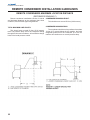
REMOTE CONDENSERS MAXIMUM LOCATION DISTANCE
(REFRENCES DRAWING C)
Remote condenser installations consist of vertical
and horizontal distances to the condenser that, when
combined, must fit within approved guidelines.
TOTAL MAXIMUM LINE LENGTH:
This should never exceed 50 feet (15.24 meters)
total. The pressure drop, due to the refrigerant flowing
through the lines and condenser, will exceed the design
limits of the head pressure control.
22
CONDENSER MAXIMUM HEIGHT:
This should never exceed 35 feet (10.66 meters).
CONDENSER MAXIMUM DROP:
The condenser should never be positioned more than
15 feet (4.57 meters) below the ice machine. the liquid
refrigerant pushed from the condenser up to the ice
machine will contribute to an overall pressure drop.
Installation and Service Manual
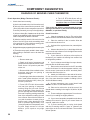
COMPONENT DIAGNOSTICS
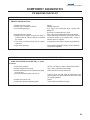
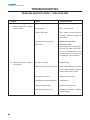
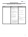
ICE MACHINE CHECKLIST
PROBLEM
CORRECTIVE ACTION
1. ERRATIC SIPHON ACTION:
O Water level not correct
O Water pan not seated on blocks
O Float leaking through
O Algae build-up in siphon
O Siphon tube to copper vent tube too short or
kinked at rear of cabinet. Siphon not istalled
on vertical.
O Too small or restricted drain line for copper
vent tube.
O High water pressure.
PROBLEM
Adjust.
Reseat water pan.
A) If float is not round bulb style, replace with
#9200377.
B) If float is round bulb style, clean.
Pour 1/4 cup household bleach through siphon.
Plastic siphon tube must be 6" (15cm) to 8" (20cm)
out rear of cabinet, if not, replace tube - if tube is
kinked, reform or replace.
Increase drain size and/or remove any restrictions.
Is flow washer installed correctly? If yes, install water pressure regulator.
CORRECTIVE ACTION
2. PUMP CAVITATING (PULLING AIR), or pump
air locked:
O Low water pressure
O Water supply line too small
O Water discharge from float directed at pump
pick-up tube
O Pump to distributor tube has air lock
O Water level set too low
O High water pressure agitating water
20 PSI (1.37 Bars) or lower remove flow washer
3/8" (.32cm) minimum water supply
Raise shelf area of float bracket 2o
Tube too long and has raise at distribution tube.
Shorten tube - be certain tube does not prevent water curtain operation
Adjust
Is flow washer installed correctly?
23
Installation and Service Manual
COMPONENT DIAGNOSTICS
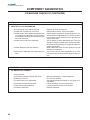
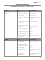
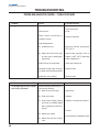
ICE MACHINE CHECKLIST (CONTINUED)
PROBLEM
CORRECTIVE ACTION
3. POOR ICE FILL ON EVAPORATOR:
O Float or dump valve leaking through
O Water pan not seated or out of level
O Water curtain out of adjustment allowing water to splash into bin and/or curtain freezing
to evaporator changing flow and freeze pattern over thermistor
O Water flow too fast over evaporator
O Water distributor tube not centered
O No control of water flow over evaporator (too
fast)
PROBLEM
Replace, or clean, as required.
Reseat pan on blocks. Level ice machine.
Adjust curtain brackets for proper alignment. Curtain brackets are adjustable 3/8" (9.5mm) up down/
front to back. Curtain should be set to just clear top
edge of water pan.
Check position of water distribution tube. The tube
should be spraying toward lower back of extrusion.
Be certain required sealing of evaporator upper extrusion area is done.
Water Distribution tube must be centered over top
extrusion of evaporator.
Check inner tube of water distribution to be 180o
from outer tube. Check restriction plug in water system.
CORRECTIVE ACTION
4. ICE BRIDGE NOT CORRECT:
O Slow harvest
A) Excessive meltage of bridge and cubes
B) Machine not level
O Control board out of adjustment
O Thermistor incorrectly mounted
O Thermistor sealant defective
O Defective thermistor
24
Mineral contamination - clean evaporator
Re-Level ice machine.
See adjusting bridge thickness for your style of circuit board.
Follow procedure to remount thermistor
Follow procedure to remount thermistor
Replace thermistor
Installation and Service Manual
COMPONENT DIAGNOSTICS
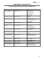
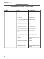
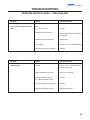
DECISION TREE BEFORE REPLACING A THERMISTOR
SERVICE SYMPTOM
COMMON MISDIAGNOSIS
ACTUAL DIAGNOSIS
1.Eratic bridge thickness
Replace thermistor
Dirty evaporator
Dirty water system
Exposed TXV bulb
Flooding TXV
2.Freezes for 2-3 minutes
Replace thermistor
then goes into harvest
3. Ice frozen to the curtain
Slushing
Ice bridge too thin
Replace thermistor
Hall switch lost target area and
made a second batch of ice
Flooding TXV
4. Ice not filling completely
Replace thermistor
Poor water flow
Replace thermistor
Water cavitation
before going into harvest
5. No ice
Premature harvest
Ice freezing to evaporator
6. Premature harvest with
Replace thermistor
Pump cavitation
no water flow or harvest
7. Thick ice at the bottom with Replace thermistor
Conintuous syphoning of water from
thin ice at the top of the slab
machine
8. Thick ice on bottom of
Replace thermistor
evaporator with no ice on
Starving expansion valve
Flooding expansion valve
the top
9. Very thick ice bridge
Replace thermistor
Dirty condenser
Low refrigerant charge
10. Will not harvest ice
Replace thermistor
Dirty condenser
11.Will not go into harvest
Replace thermistor
Hall/proximity switch out of alignment
12. Will not go into harvest
Replace thermistor
Water dripping into bin
Ambient air entering into bin
25
Installation and Service Manual
COMPONENT DIAGNOSTICS
DIAGNOSIS OF SERVEND CUBER THERMISTOR
Erratic Operation (Bridge Thickness Erratic):
A) Are the wire leads to the circuit board secure?
6. The G. E. RTV-108 silicone will set,
tack-free, in aproximately 15 minutes. Do
not allow water to contact silicone
until it is tack free.
B) Is the tip of the control flush or protrude 1/64"
(.4mm) beyond the lower evaporator extrusion?
If correctly mounted, you may feel a slight bump.
*This is the only silicone recommended for proper
sealing of thermistor by Servend International (part
#5000881, or purchase locally.
C) Is there a heavy film of sealant over the tip of the
control? A very slight film is OK. If the tip of the control
looks a milky color, the silicone is too thick.
Check Procedure:
1. Check thermistor mounting:
D) After the machine sets for 24 hours is the first
sheet of ice OK? Does each succeeding sheet
of ice get thinner? This could be a sealing problem with water in the sensor well.
2.
2. Place the machine in the ice mode. Allow the
unit to make one sheet of ice.
Bridge thickness gets progressively thinner each cycle:
3. At the end of a regular freeze time, manually harvest the ice.
A) Thermistor not properly sealed in lower evaporator molding or thermistor set too far back into
molding.
4. Observe the sheet of ice. Is the bridge thickness
even from the top to bottom? Is the bridge thinner at the
top than at the bottom?
B) To Reseal:
5. If your sheet of ice is thinner at the top than at
the bottom, your machine is suffering from a water loss
or refrigeration problem.
1. Remove water pan
2. Reach up in back of evaporator and
grasp thermistor leads and remove thermistor. Use a 1/16" punch to push thermistor out.
3. Remove dried silicone adhesive from
thermistor and clean out opening in
evaporator molding.
4. If replacing a plastic sleeve thermistor
with a metal jacket thermistor hole will
have to be reamed to 11/64" (.43cm). Do
not use a power drill.
5. Force G.E. RTV-108* silicone adhesive into front opening of evaporator
molding filling the hole until silicone
come out the back. Place thumb or finger over opening and reinsert thermistor
from rear of opening pushing toward the
front of the evaporator modling (this will
force silicone around the thermistor as
you push thermistor forward giving a
positive seal). Allow thermistor to be
flush or protrude approximately 1/64"
(.4mm) beyond face of evaporator molding with ample amount of silicone
ahesive. (1/64" equals a very slight
bump).
26
1. Clear the evaporator of any ice. This can be done
with the use of the manual harvest switch on the circuit board.
6. If you ice has an even bridge from top to bottom,
proceed with the OHM meter check.
7. Remove the control wires from the EV terminals
on the circuit board. In a dual evaporator machine, only
the left control (connected to the EV terminals) determines the thickness of the ice.
8. Attach you OHM meter to the ends of the wires.
Do not remove the control from the evaporator extrusion. Your meter should be capable of reading 5,000 to
40,000 OHMs accurately.
9. At room temerature, your control should read
ABOUT 10,000 to 15,000 OHM resistance.
10. Place an ice cube on the tip of the control. You
should obtain a reading in the range of 25,000 to 36,000
OHMs.
11. These readings are approximate. Do not be concerned if your reading are slightly different.
12. If your control responds comparable to the above
readings, this control is good. If your control does not
respond, replace the control.
13. If you are working with a 4 relay circuit board
and the ice sensing control is "open" or "shorted", the
power light on the circuit board will flash. The machine
will not operate.
Installation and Service Manual
COMPONENT DIAGNOSTICS
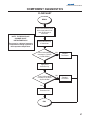
FLOWCHART
BEGIN
Remove thermistor leads
from circuit board. Connect OHM meter to
thermistor.
NOTE: THE RESISTANCE
CHANGE IS NOT
INSTANTANEOUS!!
There may be a delayed response
to temperature change opposite of
the evaporator temperature.
Place thumb on tip
of thermistor.
Does OHM reading
decrease to 7,000 to
10,000 OHMs?
NO
Replace
Thermistor
Apply ice to
thermistor tip.
Does OHM reading
increase to 25,000 to
36,000 OHMs?
NO
Replace
Thermistor
Yes
Thermistor OK.
END
27
Installation and Service Manual
COMPONENT DIAGNOSTICS
Product Operation:
If the thermistor is "open" the cuber will start in the
harvest, or hot gas cycle, on a 3 relay board:
1. Adjusting the potentiometers ("pot") will not put
the cuber into a freeze mode.
2. Proximity switch will trip control board red light
off and on with water curtain movement, but,
product will remain in harvest mode when curtain closes.
If the thermistor is "shorted" the cuber will remain in
the freeze cycle on a 3 relay board.
If thermistor passes flowchart test the thermistor is
OK - do not replace; check thermistor mounting and Erratic Operation Troubleshooting Guide for bridge thickness.
NOTE: BEFORE REPLACING THERMISTOR PLEASE
TEST USING CHECK PROCEDURE OR
FLOWCHART.
New generation circuit board (4 relays, remote
mounted transformer) - the power on light (LED) will flash
if there is a warning mode in the thermistor circuit.
NOTE: EV thermistor - Controls bridge thickness,
provides hi-temp safety cut-out on single
evaporator units and the left evaporator on
dual evaporator models.
High 2 thermistor - Dual evaporator models
only - right evaporator thermistor provides
high temperature safety shut-down.
ICE THICKNESS CONTROL REPLACEMENT
1. Shut off water and electric supply to the ice
maker.
2. Remove the float valve and water pan from the
machine. Remove the side panel from the control box side of the machine.
3. Use a 1/16" punch or allen wrench to push the
control out of the extrusion. Clean the old silicone out of the hole.
4. Remove the old control from the machine.
Thread the new control through the machine from
the compressor compartment. Push the control
tip through the enclosure to the evaporator.
5. When routing the new control wires to the circuit
board be sure the wires do not touch any hot
gas lines. Attach the lead wires to the circuit
28
board in the appropriate positions. There is no
polarity in the wires of the ice thickness control.
6. If your old control has a plastic jacket, you must
redrill the control hole. Use a 5mm (11/64") drill
bit for this purpose. Use the drill bit by hand to
enlarge the hole to fit the metal jacketed control.
7. Using GE RTV-108 clear silicone only fill the hole
with silicone. This silicone is available from your
local Servend Distributor.
8. Immediately after filling the hole with silicone,
place your thumb over the front of the hole for
ice sensing control. Push the new control into
the hole from behind the evaporator. This will
allow the silicone to encompass outside the
contrl jacket. Continue to push the control into
the hole until you can feel the conrol hitting your
thumb. Never make a sharp bend with the control or allow the wire to loop behind the evaporator. this can produce internal damage to the control.
9. The ice thickness control should be flush or protrude through the hole 1/64" (.4mm). You may
feel a slight bump.
10. With your thumb still over the opening, wipe your
thumb sideways over and off the control. This
will allow a very slight silicone seal to remain on
the control tip.
11. Reinstall the side panel, water pan, float valve
and restore all utilities to the machine.
12. Wait for 15 minutes before allowing water to run
over the evaporator. This will allow the silicone
to dry tack free.
13. Check the water level in the water pan. turn the
machine to the ICE position.
14. Allow the machine to make one batch of ice. You
may check this sheet for proper bridge thickness.
If adjustment is necessary, please follow the procedure for your particular machine.
Installation and Service Manual
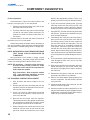
COMPONENT DIAGNOSTICS
SAFETY THERMO-DISC / FAN CYCLE CONTROL
Ice Thickness Control Adjustment
1. Adjustment to the bridge thickness is done at the
circuit board. On the bottom (front) of the board
you will find either two round black potentiometers
or a set of 8 DIP switches. Please follow the instructions below for the particular type of board
you have. For optimum ice production and harvest, it is recommended that a 5mm (3/16") bridge
thickness be obtained. In any event, you must not
have a bridge thickness less than 3mm (1/8").
2. TO ADJUST A BOARD WITH TWO POTENTIOMETERS (3 RELAY):
If the machine had been running properly prior to
failure of the thermistor, run the machine through
one complete cycle without making any adjustment
in the bridge thickness. If further adjustment is
necessary, adjust the FINE (right) potentiometer
first. Turn the dial to a higher number for a thinner
bridge thickness. Turn the dial to a lower number
for a thicker bridge thickness. Always wait for one
complete cycle after making any adjustment before readjusting the machine. If further adjustment
is necessary beyond that obatinalbe with the fine
adjustment, you may utilize that COARSE (left)
potentiometer. This dial should only be moved one
marked graduation at a time. One mark is equivalent to about 3/4 turn of the fine dial. The coarse
dial should be moved one mark then fine tuned
with the fine dial.
3. TO ADJUST A BOARD WITH 8 DIP SWITHCES
(4 RELAY)
If the machine had been running properly prior
to failure of the thermistor, tun the machine
through one complete cycle without making any
adjustment in the bridge thickness. If further
adjustment is necessary, adjust the DIP
swithces. To have a thicker bridge, turn the next
(right) switch "on". To have a thinner bridge, turn
the next (left) switch "off". It is acceptable to have
all the switches either on or off. Follow the wedge
above the switch case for thicker or thinner
bridge. To turn the swithc "on" push the top of
the swithc down. If further adjustment is necessary, you may adjust the potentiometer. This "pot"
is located to the left of the 8 DIP switch case.
Remember this is a coarse adjustment. Move
this pot no more than one (1) graduation at a
time. You will then have to adjust the DIP
switches for proper thickness.
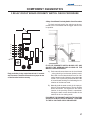
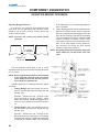
SAFETY THERMO-DISC
The thermo-disc is a safety control located on the
evaporator inlet for 3 relay siphon systems. This disc is
insulated to prevent ambient air from effecting the operation. The disc is non-adjustable and set to open at 120oF/
49oC (closes at 95oF/35oC) evaporator inlet line temperature. The disc prevents the cuber from over heating if the
product should remain in a hot gas harvest cycle for any
reason.
On a remote cuber, a thermo-disc(s) is wired in series
with the compressor contactor. The thermo-disc will provide a second high temperature safety cut-out device to
protect the ice maker during the pump down cycle when
the circuit board and thermistor does not control the unit.
To Check the Safety Thermo-Disc
Disconnect the thermo-disc RED leads from the machine. With an OHM meter check for continuity - if ther is
none, replace the disc if temperature of disk is below 90oF
(32oC).
Should thermo-disc be open becuase of hi-temp safety
cut-out, you may reclose the disc by manually holding the
contactor closed to run the compressor and cool the evaporator inlet line to be certain the thermo-disc will reclose. Do
not hold the contactor in for more than 30 seconds.
FAN CYCLE CONTROL
This is a high side pressure control that cycles the condenser fan motor off at approximately 180 PSI (12.4Bars)
and on at 250 PSI (17.2Bars). Its purpose is to maintain a
minimum head pressure for proper operation in low ambient conditions.
Remote systems and dual evaporator models utilize
fan cycle controls.
To check:
Install a high side gauge to the hi-side service valve.
DO NOT attach to the receiver valves. Operate the system
and observe the pressures the fan motor cycles. If the cycling pressure is more than +/- 10% out of the control range,
replace the control - it is nonadjustable.
NOTE: CONCAVED SIDE OF BLADE IS FACING FAN
MOTOR ON ALL AIR COOLED SERVEND
CUBERS AND REMOTE CONDENSERS.
29
Installation and Service Manual
COMPONENT DIAGNOSTICS
HEAD PRESSURE CONTROL VALVE
(REMOTE CONDENSERS ONLY)
A modulating control to maintain proper receiver
operating pressure for correct defrost. At outdoor temperatures above 70oF (21.1oC) the refrigerant flow is from
the condenser to receiver. At temperatures below 70oF
(21.1oC) the valve will enter a "by-pass mode" and the
refrigerant flow will be from discharge line to receiver
allowing the compressor discharge vapor to increase the
receiver pressure by "by-passing" the condenser. The
head pressure control is designed to only operate in bypass at temperatures below 70oF (21.1oC).
Check Procedure
Install gauge at receiver and monitor pressure. With
temperature below 70oF (21.1oC) receiver pressure will
be 200 PSI (13.7Bars) to 240 PSI (16.55Bars) +/- 5 PSI
(.34Bars).
A head pressure control that stays in by-pass may
be the result of a system that is short of refrigerant. Before replacing the head pressure control, check fan cycling control. If it is not cycling, add refrigerant in 2 pound
(1Kg) increments and allow product to run 10/15 minutes to determine operation. Do not exceed 4 pounds
(2Kg) total during this test. If the addition of refrigerant
corrects head master operation you must now locate the
leak, correct, and properly recharge the system.
CAUTION: When removing a head pressure control,
always snap off the stub line at the dome BEFORE
using a torch to heat lines to remove. When reinstalling be sure the dome area has ample heat-sink
BEFORE applying heat to valve.
High Pressure Cut-Out
All Servend water cooled and remote condenser
products contain a high pressure cut-out. The function
of this switch is to turn the ice maker off in the event of
excessive pressure developing in the high pressure side
of the refrigerant system. This switch will open the power
circuit to the circuit board at 450 PSI (31Bars) pressure
on current units. It is a manual reset control located beside the power toggle switch. To reset this control, push
in the red button.
In the event this control shuts down the machine,
please find teh reason for this shut down. Correct any
necessary problems before restarting the machine.
30
Water Regulating Valve
THE WATER REGULATING VALVE IS USED ON
WATER COOLED CUBERS ONLY...The valve is
mounted in the condenser water line. Its function is to
maintain the proper operating head pressure by controlling the amount of water flow through the condenser.
The valve is adjustable and factory set to maintain condenser discharge water at 105o/108oF (39o/42oC). Setting the water regulating valve to maintain dishcarge
water temperature eliminates the need to enter the sealed
refrigerant system. Water temperaute should be taken
as close to the condenser discharge as possible. This
water temperature will equate to operating head pressures of approximately 230/240 PSI (15.86/16.55 Bars).
Should adjustment be required, the valve has an
adjustment stem on the top. After allowing the cuber to
operate for 6 minutes into the ice making cycle to balance the system, turning the adjusting stem CW will increase the discharge water temperature and CCW will
decrease the discharge water temperature.
The water regulating valve must close off condenser
water flow completely during hot gas "harvest" cycle. If
the valve fails to close during the harvest mode, the condenser will continue to condense the hot gas needed for
the harvest cycle and produce long harvest times.
Leaking water regulating valve are normally the result of scale build-up on the valve diaphragm and the
valve should be flushed, not replaced. To flush the valve,
open the adjusting stem full open CCW (or force the valve
spring up with a screw driver) open and close the water
supply to the condenser resulting in the flush action.
Should this not correct the problem replacing the valve
diaphragms can be done without entering the sealed refrigeration system.
Damage to the water regulating valve may also be
caused by water hammer. Water hammer will result from
condenser inlet and drain lines being reversed or defective valve stops in the supply line. Proper installation of
water cooled equipment should always include a antiwater hammer standpipe or expansion tank in the supply inlet water line as close to the cuber as possible.
Installation and Service Manual
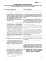
COMPONENT DIAGNOSTICS
HOT GAS VALVE / COMPRESSOR CONTACTOR / CHECK PROCEDURE
Hot Gas Valve
Compressor Contactor
Servend employs a hot gas defrost harvest method.
When the ice reaches the proper temperature, the ice
sensing thermistor initiates the board to open the hot
gas bypass valve. This electrically operated solenoid
valve will then allow hot discharge refrigerant gas as it
leaves the compressor to return to the inlet of the evaporator. The flow of liquid refrigerant out of the expansion
valve will then cease. The hot refrigerant warms the
evaporator therefore allowing the ice to melt and slide
off of the evaporator.
CAUTION: 230 VOLT MODELS - CONTACTOR
BREAKS ONE POWER LEG ONLY - ICE MAKER IS
STILL LIVE (HOT).
If the hot gas fails to open, check the electric power
supply to the coil of the valve. This power supply comes
to the coil from the circuit board and should be energized when the red LED is energized. If the coil is
envergized but the valve still fails to operate, you have a
sticking valve that needs to be replaced.
A leaking valve can cause excessive freeze times,
uneven bridge thickness, high suction pressures, etc.
A leaking hot gas valve is difficult to troubleshoot.
Several methods to determine if this valve is leaking in
the closed mode is as follows:
The hand temperature method - Place your hand
on the outlet line of the valve. The outlet line of the
valve should feel ambient temperature or a little
cooler.
The contactor serves as the voltage supply switch
for the compressor circuit. Voltage to the coil of the
contactor is supplied by the control board relay on selfcontained models (see diagrams). Remote models are
wired directly across the supply line from the toggle
switch. The coil receives power through the low pressure cut-out and thermo-disc.
Check Procedure (Single Phase)
Top two (2) screws of contactor should always have
line voltage supply present. The lower two (2) screws
should have line voltage when the contactor closes.
The contactor coil must receive line voltage from teh
control board relay. If the coil will not close the contactor:
A) Check the coil with an OHM meter for continuity.
B) *Check for proper voltage supplied to coil.
*NOTE:High impedance digital meter may show voltage from the control board, but that voltage may not
carry a current load. Test light 25W or higher or a
low impedance dial type meter should be used when
testing output voltage from control board.
The use of an electronic sight glass - Can be beneficial in the leak detection. Install the probes on the
oulet line of the valve, several inches apart. If there
is a small leak in the valve, the instument should
detect hot gas condensing due to the pressure drop
and cooler temperatures of the evaporator section.
Another leak detection method for the hot gas
valve is the use of a pinch off tool - By closing the
line between the hot gas valve and the evaporator,
you should be able to determine if the valve was
slightly leaking through.
31
Installation and Service Manual
COMPONENT DIAGNOSTICS
COMPRESSOR AND STARTING COMPONENTS CHECK OUT PROCEDURE
When compressors fail to start or run properly, it is
normally the external electrical supply or start components
that are defective. The over-load protector, start and/or run
capacitor, relay, control board, safety controls, etc:
1. With machine in ice position and contactor closed,
check voltage at compressor terminals. NO voltage will require a back check from compressor to
determine where the voltage supply is interrupted.
Correct as required. The load voltage, while compressor is trying to start, should not be less than
95% of rating required for product.
Line voltage and line size effect life expectancy of
electrical components, compressor, motor coils,
etc. Line voltage should be maintained at 95% of
lowest rated voltage.
NOTE: For 50 HZ application on dual rated 50/60 models, load voltage, while compressor is starting
must not be less than 95% of 50 HZ rating.
NOTE: Poor line quality voltage will cause many erratic electrical problems. Every electrical product, ice machine, dispenser, walk-in, reach-in,
air conditioner, etc. requires proper power supply to operate. Be certain your voltage check is
load voltage, not line.
2. A defective capacitor or relay may prevent the
compressor from starting. If the compressor attempts to start, but in unable to do so, or if the
compressor hums or trips out on the over-load
protector, check:
Relay - Potential type, contacts normally closed.
Contacts open by C.E.M.F. from compressor at
approximately 80% of operating speed removing start capacitor from circuit. Both start and run
winding and run capacitor remain in circuit.
Capacitors - Any capacitor found to be bulging,
leaking or damaged should be replaced.
CAUTION: Before removing leads for testing purposes, short across capacitor with a 10K OHM resistor to discharge capacitor if capacitor does not
have bleed resistor installed.
A quick check is to replace suspected capacitors with a
known good capacitor. Be sure specified capacities are used.
If capacitor analyzer is not available, an OHM meter
may be used to check start capacitors for short, or open,
32
circuits. Set the OHM meter to its highest scale and connect prods to capacitor terminals.
A) With a good capacitor, the indicator should first move
to zero (0) and then gradually increase to infinity.
B) If ther is no movement of the OHM meter indicator, an open circuit is indicated.
C) If the OHM meter indicator moves to zero (0)
and remains there, or on low resistance reading, a short circuit is indicated.
D) Remember this check does not determine that
capacitor will deliver the MFD/UFD rating required, only detects shorted or open plates.
E) Capacitors that show any sign of leakage of electrolyte, or damage of can, should be replaced.
DO NOT TEST!
CAUTION: Turn power off. Before removing supply
leads to compressor, short across both capacitor
terminals to discharge capacitors.
1. Using an OHM meter check for continuity from
terminals C to R, and C to S. If the compressor
is hot, wait one (1) hour for compressor to cool
and recheck. the internal over-load protector can
cause a lack of continuity. If continuity cannot
be established through all motor windings, the
compressor must be replaced.
2. Check compressor for ground by means of a
continuity check between terminals C, R and S
to the compressor shell or copper refrigeration
line (be sure to scrape metal surface clean to
get good contact). Continuity present, the compressor windings are grounded and the compressor must be replaced.
If compressor starts, but trips, repeatedly on the overload protector, check:
Operating pressures should be within limitations of
normal operating conditions.
Check the amperage drawn while the compressor is
operating. Under normal operating condintions, the continuous amperage drawn will seldom exceed 100% of
compressor nameplate amperage and should never exceed 120% of nameplate amperage. High amperage can
be caused by: Low Voltage, Undersized Lines, High
Head Pressure, High Suction Pressure, Defective
Running Capacitors or Starting Relay, Compressor
Mechanical Damage.
Installation and Service Manual
COMPONENT DIAGNOSTICS
TOTAL ICE CAPACITY / ICE PRODUCTION CHECK
Thermostatic Expansion Valve(s)
Total Ice Capacity
The following suggestions are made with the understanding that:
Ice capacity of any ice maker is affected by many
operating conditions, such as water and air temperatures
and location factors. Please review the capacity tables
in this manual for average 24 hour capacity under various conditions. All printed capacity ratings are +/- 10%
except 50 HZ units.
A) The condenser and fan blade are clean and have
proper operating conditions.
B) Water supply to the product is correct and water
flow over the evaporator is correct.
C) System charge is correct.
D) TXV bulb is properly located and secured to the
line and correctly insulated.
E) Hot gas valve(s) not leaking through.
F) Discharge pressure OK.
50 HZ units cycle time will increase by approximately
12% and capacity will decrease by approximately 17%.
Ice Production Check
Take air temperature, if air-cooled condenser, at the
inlet of condenser, 2" from condenser fins.
Starving Valve - Product Symptoms:
Incoming water temperature at the outlet of the float valve.
1. Suction pressure lower than normal for the operating conditions.
Cycle time (CT) = Freeze time + harvest time, in minutes.
2. Ice production lower than normal and/or none.
3. Ice pattern on evaporator (if any) thin at top and
thick at bottom.
Flooding Valve - Product Symptoms:
1. Ice production lower than normal or none.
1440 divided by CT = number cycles per 24 hours.
Weight of ice from one cycle in pounds.
EXAMPLE:
Weight x cycles/day = total production/24 hours
Compare your known facts to the production tables
found in the product service manual.
2. Suction pressure stabilizes at higher than normal and does not continue to modulate and decline (may start to slowly rise).
3. Ice pattern will be very thick from top to bottom
of evaporator - unit may not enter harvest.
4. Frost on the suction line is normal on medium
temperature refrigeration equipment. Frost extending onto the compressor shell may not be a
problem. Before checking the sealed system,
check external conditions such as spacing
around poor ventilation, dirty condenser, etc.
CAUTION:
A) On models with the expansion valve bulb clamped to
a vertical section of the suction line - capillary tube
should point upward. This is done to eliminate the
possibility of contaminates from plugging capillary
tube. DO NOT RELOCATE THE BULB.
B) Superheat settings and bulb charges are designed
specifically for Servend ice makers, and vary by model
and refrigerant used. Be sure to replace expansion
valves by part number and with Servend parts only.
33
Installation and Service Manual
COMPONENT DIAGNOSTICS
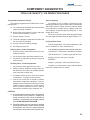
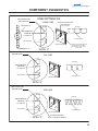
ACCEPTABLE ICE
JUMBO CUBE
SHARP CORNERS
DETAIL "A"
SHARP CORNERS,
PARALLEL SIDES
ON CUBES
BRIDGE 1/8"
TO 3/16"
BRIDGE WILL VARY
FROM TOP TO BOTTOM
TYP. ALL SIZES
FRONT VIEW
TOP VIEW
EVENLY SPACED
DETAIL "A"
FULL CUBE
SHARP CORNERS
BRIDGE 1/8"
TO 3/16"
SHARP CORNERS,
PARALLEL SIDES
ON CUBES
EVENLY SPACED
DETAIL "A"
FRONT VIEW
AIR POCKETS
RANDOMLY SCATTERED
AT BACK OF MINI
CUBE ONLY
MINI CUBE
SHARP CORNERS
BRIDGE 1/8"
TO 3/16"
SHARP CORNERS,
PARALLEL SIDES
ON CUBES
EVENLY SPACED
DETAIL "A"
34
TOP VIEW
FRONT VIEW
TOP VIEW
Installation and Service Manual
COMPONENT DIAGNOSTICS
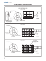
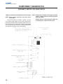
UNACCEPTABLE ICE
LONG HARVEST OR
UNIT NOT LEVEL
JUMBO CUBE
SEE DETAIL "A"
POOR WATER DISTRIBUTION
OVER EXTRUSION
TYP. ALL SIZES
TOP VIEW
BRIDGE OUTSIDE
RANGE OF
1/8" TO 3/16"
HOUNDS TOOTH
HOLLOW CUBES
UNEVEN TRACKING
COMPLETE SLAB OF ICE
DETAIL "A"
LONG HARVEST OR
UNIT NOT LEVEL
IF WHITE ICE OR POOR DISTRIBUTION
OCCURS DUE TO SLUSH, TEST
AFTER EXCESSIVE SLUSH CLEARS
TYP. ALL SIZES
FULL CUBE
TOP VIEW
BRIDGE OUTSIDE
RANGE OF
1/8" TO 3/16"
HOLLOW CUBES
HOUNDS TOOTH
UNEVEN TRACKING
DETAIL "A"
LONG HARVEST OR
UNIT NOT LEVEL
MINI CUBE
TOP VIEW
BRIDGE OUTSIDE
RANGE OF
1/8" TO 3/16"
HOLLOW CUBES
HOUNDS TOOTH
UNEVEN TRACKING
DETAIL "A"
BITE MARKS GREATER
THAN 1/8" ON MINI CUBE ONLY
35
Installation and Service Manual
COMPONENT DIAGNOSTICS
3 RELAY CIRCUIT BOARD SEQUENCE OF OPERATION /
ADJUSTING BRIDGE THICKNESS / 3 RELAY CIRCUIT BOARD
3 Relay Circuit Board Sequence Of Operation
Adjusting Bridge Thickness
When the toggle switch is placed in the ice mode,
the control board activates the water pump, condenser
fan motor (on air cooled units), the compressor contactor.
For optimum ice production and maximum cube
seperation, the ice connecting the individual cubes
should be a minimum of 1/8" (.32cm) thick at the center
of the ice waffle.
The water pump circulates the water supply across
the evaporator. The refrigeration system chills the evaporator removing removing the heat from the water and ice
is formed. This process continues until the ice rolls over
the evaporator bottom extrusion covering the thermistor
sensing tip. At approximate 26oF (-3.3oC) ice temperature the thermistor signals to the control board to start
the harvest mode.
The control board shuts down the water pump, condenser fan (on air cooled units) and activates the hot
gas valve for the harvest mode. When the water pump
stops, the water in circulation returns the water pan increasing the water level and creates the siphon action.
The siphon action cleans the water pan. The float assembly allows fresh water to fill the water pan for the
next cycle.
With the hot gas valve open the evaporator warms
up to allow the ice to move off the evaporator. The ice
travle forces the water curtain to open. The opening of
the water curtain interrupts the proximity switch circuit,
closing the hot gas valve. The ice falls into the storage
bin, the curtain closes activating the proximity switch and
the next refrigeration cycle begins. This operation is repeated until the ice drop during harvest can not clear the
water curtain. The curtain being held open for approximately 15 seconds causes the proximity switch to indicate a full bin, the curtain will close and the ice machine
will start in a refrigeration mode. The cycle(s) are repeated until the bin is once again full and the water curtain opens allowing the proximity switch to shut down
the ice machine operation.
CUBES
BRIDGE 1/8"
(0.32 cm)
3 Relay Circuit Board
These five (5) steps must be followed in proper sequence:
1. Set fine "pot" to 50
2. Set coarse "pot" to 50
3. Allow cuber to build ice until bridge appears to
be correct thickness (1/8" to 3/16" (.32 to .49cm)
thick
4. With water curtain in place, slowly advance (towards 100) coarse "pot" until harvest mode begins - allow the ice to harvest and check bridge
thickness to be 1/8" to 3/16" (.32 to .49cm) thick.
5. Additional adjustments to be made with fine "pot"
turning 1/2 to 1 division at a time until 1/8" to 3/
16" (.32 to .49cm) bridge is achieved. The lower
the number, the thicker the bridge.
NOTE: Too thin of a bridge (less than 1/8" (.32cm)
will cause harvest problems.
NOTE: Never judge the thickness from the first batch
of ice produced - the first cycle is a machine
balance cycle. Always wait for the second
cycle before making any adjustments.
36
Installation and Service Manual
COMPONENT DIAGNOSTICS
3 RELAY CIRCUIT BOARD PROXIMITY SWITCH CHECK PROCEDURE
3 Relay Circuit Board Proximity Switch Check Procedure
To check proximity switch, the switch must be connected to the circuit board with the toggle switch in the
ice position.
CD
CD
EV
EV
(-)
N/C
(+)
IF LED OF PROXIMITY SWITCH BLINKS OFF AND
ON WITH THE OPENING AND CLOSING OF THE
WATER CURTAIN PROCEED:
Early production 3 relay control boards had a 7 terminal
strip connector. Terminals CD must have a jumper for the
control board to function correctly.
A) Push manual harvest button on the circuit board
- cuber should go into harvest (defrost) mode.
Red LED of control board should come on indicating harvest mode. Manually open the water
curtain - LED of proximity switch and RED LED
of control board should go out indicating the termination of the harvest mode.
B) Manually hold the water curtain in the open position for 15 seconds maximum. The ice machine
should shut down. This signals the bin control
function of the proximity switch is operational.
Closing the water curtain should restart the ice
machine in the ice making mode.
FAILURE OF THE PROXIMITY SWITCH TO FUNCTION
AS NOTED IN BOTH A AND B ABOVE - PROCEED
TO THE DC VOLTAGE CHECK PROCEDURE.
37
Installation and Service Manual
COMPONENT DIAGNOSTICS
PROXIMITY SWITCH VOLTAGE CHECK
3 Relay Circuit Board Proximity Switch Check Procedure
NOTE: These checks should be done with proper
line voltage.
Set the multi-meter to read D.C. voltage - turn the
ice machine toggle switch to the center (off) position.
Disconnect the Red, White and Black leads of the proximity switch from the control board. Turn the toggle switch
to the up position (ice). Check for voltage at the positive
and negative terminals on the control board.
38
NOTE: Voltage above 24 VDC will damage proximity
switch - replace both the control board and
proximity switch.
Voltage below 13 VDC proximity switch will
be intermittent - replace control board.
Installation and Service Manual
COMPONENT DIAGNOSTICS
4 RELAY CIRCUIT BOARD SEQUENCE OF OPERATION
4 Relay Circuit Board Sequence of Operation
Place the toggle switch to the ice making mode. This energizes 3 of the 4 control board relays to activate the dump
solenoid, compressor contactor (a pump down solenoid on a
remote system), fan motor and the water pump. See note "A"
for dump switch setting. The dump solenoid relay will de-energize 6 to 9 seconds into the freeze cycle, terminating the dump
cycle.
Removal of ice from the bin will allow the water curtain(s)
to close completing the Hall switch circuit(s) reactivating
the ice making cycle.
NOTE: The cuber can be placed in the harvest mode
(hot gas defrost) at any time during the freeze
cycle by depressing the manual harvest
switch. To terminate the harvest cycle, momentarily open the water curtain(s).
Relay operation and special and special amber signal functions on the control board are indicated by the 7 LEDs (3 Green,
3 Amber and 1 Red):
Green LED:
Water pump, fan motor, dump solenoid,
compressor contactor and pump down
solenoid on remote systems.
Amber LED:
Water curtain 1 and/or 2 and power ON
signal
Red LED:
Hot gas solenoid
The ice forms to its predetermined thickness and rolls
over the evaporator bottom extrusion and covers the thermistor tip. The ice increases the thermistors' resistance
- this signals the termination of the freeze cycle and the
de-energizing of the water pump and fan relay (Green
LED). The hot gas solenoid realy (Red LED) is energized. This is accomplished at about 26oF (-3.3oC).
NOTE: The condenser fan on remote models is
wired direct to the power line and may operate throughout the harvest cycle. (See
wiring diagrams)
As the hot gas warms the evaporator(s), the ice is
released. When the ice is released from the evaporator(s)
it momentarily moves the water curtain(s) open. This
movement removes and returns the magnet to the Hall
switch(es), resetting the control board circuit to the next
ice making mode. The dump solenoid may be energized
at this time if the required number of harvest cycles have
occurred. This ice making cycle will repeat until the storage bin is full.
* When the ice fills the bin it will hold the water
curtain(s) in the open position. With an open water
curtain(s), the Hall switch(es) will signal the control board
holding circuit for the de-energizing of the compressor
relay (Green LED) shutting down the ice machine after
30 seconds. The power on (Amber LED) is the only LED
operational in a "full bin" mode, except on C-12 - one
curtain may indicate bin full, 2nd may close, lighting LED.
The cuber will not initiate a freeze or harvest
cycle with the water curtain(s) open or removed. Once the freeze cycle has been initiated, the water curtain(s) can be open or removed at any time.
*
On remote system, the shut-down of the compressor will be through the pump down control.
The compressor will continue to operate until the
system low side pressure is reduced to 13 PSI
(.90 Bars). On start-up the pump down solenoid
opens allowing the low side pressure to reach
45 PSI (3.10 Bars) closing the control contacts
allowing the compressor to start.
Effective with ice machines shipped from Servend
on September 1, 1994 the following changes were incorporated into the 4 relay circuit boards.
1. There is a delay programed on the board to disregard the thermistor at the start of the ice making cycle. This delay of eight minutes is to prevent
the thermistor from going into the harvest cycle
prematurely. Premature harvest may occur because of slushing conditions, water conditions,
remote pull down, etc. This delay can be bypassed
if you press the manual harvest switch on Solitech
circuit boards for the next cycle.
2. There is a maximum harvest time of nine minutes placed in the circuit. This will prevent the
machine from staying in harvest too long. The
unit will automatically reset itself if it is in a long
harvest. A situation like this can occur if the ice
bridge is set too thin, the evaporator is dirty or
the unit is in premature harvest.
3. A change was made to keep the hot gas solenoid valve open until the water curtain closes or
15 seconds elapses with the curtain open if the
unit is in a bin full mode. In the past, the hot gas
solednoid valve was de-energized when the curtain began to open. In the event the machine
39
Installation and Service Manual
COMPONENT DIAGNOSTICS
4 RELAY CIRCUIT BOARD SEQUENCE OF OPERATION
was not perfectly level, this could cause ice
"hang-up". If the curtain is open more than 30
seconds, the machine will shut down on bin full.
4. The water pump will be de-energized for eight
seconds after each dump cycle. This will allow the water system to clear itself of air. The
pump will then start with no water cavitation. The
delay follows the normal six second water dump
cycle. During the eight second period, the
manual harvest switch is inoperative.
NOTE B
POWER ON LED INDICATOR
(Multi-purpose warning signal)
Steady on indicates power to circuit boar
Flashing light indicates:
Solitech
DFE
-Hi-temp safety cut-out
SR***
SR***
(CO 115oF (46.8oC)/CI 95oF (35oC)
-Shorted thermistor
MR**
MR**
-Open thermistor
MR**
MR**
NOTE A
-Missing thermistor
MR**
MR**
Dump Switch/Water Curtain(s)
-Mis-wired thermistor
MR**
MR**
Dump switch ... The left and middle switch will control number of cycles per dump. Factory setting is to dump
every cycle - 1st and 2nd switches in the down position.
To program the dump cycle for every 3rd cycle, move
the 1st switch to the up position. To program for every
5th cycle, return the 1st switch to the down position and
move the 2nd switch to the up position.
-Curtain switch set incorrectly
example ... will flash when
machine has two thermistors
and curtain switch is set for
on curtain
Curtain switch (the right switch in the bank) ... In the
down position it is set for 1 curtain. In the up position it is
set for 2 curtains as noted on the circuit board.
-Single evaporator machine
and curtain switch is set for
two curtains
MR**
MR**'
Remote Pump Down Cycle:
* SR - Self resetting
With a full bin signal (water curtain remains open),
the Hall switch circuit is incomplete. This de-energizes
the liquid line (pump down) solenoid. The compressor
will continue to operate and pump down the low side of
the system. The low pressure cut-out control contacts
open de-energizing the ice machine at 13 PSI (.90 Bars).
** MR - Manual resetting. Toggle switch must be turned
off and returned to the ON position to manually
reset circuit board.
The ice machine will stay off until sufficient ice is
removed from the bin to restore the Hall switch circuit
when the water curtain(s) closes. The closed Hall switch
circuit energizes the liquid line (pump down) solenoid
raising the low side system pressure to 45 PSI (3.10
Bars). This increase in pressure closes the low pressure
cut-out control contacts starting the next freeze cycle.
40
Curtain switch light goes out:
***
If evaporator temperature rises above 140oF
(43oC) reset is manual
Installation and Service Manual
COMPONENT DIAGNOSTICS
4 RELAY CIRCUIT BOARD SEQUENCE OF OPERATION
NOTE C
Hall Switch/Proximity Switch
This board will function with either a Hall or proximity switch. There is a sleeve jumper on the circuit board
that must be positioned for the type of switch used. The
circuit board sleeve jumper comes preset for Hall switch
operation.
To be able to determine if you have a Hall or proximity switch, look at the body of the switch. The Hall switch
has threads the entire length of the switch body while
the proximity switch has only about 1/2 the length of the
entire body. the proximity switch has an LED light in the
side of the body. The Hall switch does not have an LED
in the body, it uses the light on the 4 relay circuit board.
The Hall switch can only be used on teh 4 relay circuit
board.
41
Installation and Service Manual
COMPONENT DIAGNOSTICS
ADJUSTING BRIDGE THICKNESS
Adjusting Bridge Thickness
For optimum ice production and maximum cube
seperation, the ice connecting the individual cubes
should be 1/8" to 3/16" (.32cm to .475cm) thick at the
center of the ice waffle.
NOTE: Less than 1/8" (.32cm) may cause harvest
problems.
CUBES
BRIDGE 1/8"
(0.32 cm)
The ice thickness switch bank (a set of 8 DIP
switches) is factory set for a normal ice bridge thickness
of 1/8" (.32cm).
NOTE: Never judge the thickness from the first batch
of ice produced - the first cycle is a balance
cycle. Always wait for the second cycle before making any adjustments.
Should a desire be for a different thickness, adjust
as follows:
1. Thinner Bridge - Move one switch at a time to
the OFF position and check the bridge after the
harvest cycle.
Example - Switches are set 1 through 4 ON.
Place switch #4 to the OFF position - check
bridge after harvest. If additional adjustment is
required, return switch #3 to the OFF position,
etc.
2. Thicker Bridge - Move one switch at a time to
the ON position and check the bridge after the
harvest cycle.
Example - Switches are set 1 through 4 ON.
Move switch #5 to the ON position - check bridge
thickness after harvest. If additional adjustment
is required for a thicker bridge, move switch #6
42
to the ON position, etc. until desired bridge thickness is reached.
3. If after adjusting the DIP switches additional adjustment is needed, please use the coarse adjustment. This potentiometer adjustment is to the
left of the DIP switches. With a DFE mechanical
relay circuit board for thicker ice, please turn this
counter clockwise. For thinner ice with a DFE
mechanical board, turn the potentiometer clockwise. For all other boards, turn the potentiometer clockwise for thicker ice while turning
counter clockwise for thinner ice.
NOTE: Any bridge thickness adjustment during the
freeze mode will not take effect until next
cycle.
Installation and Service Manual
COMPONENT DIAGNOSTICS
HALL SWITCH CHECK PROCEDURE 4 RELAY CIRCUIT BOARD
NOTE: The Hall switch can only be used on a four
relay board. When used on a four relay board,
the sleeve jumper must be set to Hall operation. Switch damage may result in teh proximity switch position.
The Hall switch will serve the same basic function
as the proximity switch on the 3 relay control board, with
the following exceptions:
A) No LED in switch - LED (LED is Amber) is located on the circuit board.
B) Switch requires a "S" pole magnet to turn on,
not a metal target. The "S" pole magnet is
mounted in teh side wall of the water curtain.
NOTE: Opening and closing the water curtain should
cause the curtain LED on the control board
to be "on" with the curtain closed and "off"
with the curtain open. Failure to function as
described proceed:
1. Check incoming voltage. Voltage between circuit board terminals L1 and L2 must be within
the voltage stated on the machine name plate.
2. Sleeve jumper on control board must be set for
Hall switch - see circuit board diagram.
3. Place the power toggle switch in the ice making
mode. (Power LED light on)
4.
Check to see switch is wired correctly on control board:
RED
=(+)
GREEN
=(N/C)
BLACK
=(-)
5. Disconnect the red, green and black leads of
Hall switch from control board.
6. Measure the DC voltage between (+) and (-) on
control board:
A) Voltage must be between 12 - 24 VDC.
B) If voltage is below 12 VDC, replace control
board
C) If voltage is above 24 VDC, replace both the
control board and the Hall switch.
7. Place a jumper across terminals (-) and (N/C).
The curtain LED on the control board should turn
"on" and the freeze mode should begin. Failure
of the LED to turn "on", replace the control board.
8. Remove jumper across terminals (-) and (N/C)
and place the jumper across terminals (+) and
(N/C) curtain LED should turn "off". Failure of
LED to turn off replace control board.
9. If control board has proper voltage (12 - 24 VDC)
and functions per #7 and #8 above, replace Hall
switch.
43
Installation and Service Manual
TROUBLESHOOTING
PROBLEM ANALYSIS GUIDE - 3 RELAY BOARD
Problem
Cuber not operating
A) Indicator lights "off" - no power
to circuit board
B) Indicator lights "off" - power to
circuit board
44
Cause
Toggle switch in center "off" position
Corrective Action
Place switch in "on" position
Toggle switch
Test - if bad, replace
Thermo-disc open
Test - replace if won't reset automatically - determine reason for
open switch
High pressure cut-out open won't reset
Depress manual reset determine cause:
Water supply shut-off, water pressure too low, water valve defective or out of adjustment, water
condenser dirty or corroded, unit
overcharged, cut-out defective.
No target on curtain
Replace target
Target not in proximity switch field
Water curtain drifting out of switch
range - reduce clearance between
curtain and proximity switch
No curtain movement
Adjust proximity switch
Fuse blown on circuit board (8 amp)
Replace fuse
Faulty proximity switch
Replace proximity switch
Unit off because bin is full
Remove ice from door - eliminate
curtain hang up
Installation and Service Manual
TROUBLESHOOTING
PROBLEM ANALYSIS GUIDE - 3 RELAY BOARD
Problem
Circuit board indicator
lights "on"
Problem
Cuber remains in freeze cycle
Cause
Compressor does not run:
A) Check circuit board relay
Corrective Action
B) Check contactor
Replace if defective
C) Compressor overload open
Permit overload to cool and reset
or replace
D) Check compressor and start
components
Replace as required
Replace if defective
Compressor runs, does not cool:
A) Low charge
Leak check - recharge
B) Hot gas solenoid leaking
Replace
C) Defective expansion valve
Replace
D) Inefficient compressor
Replace
E) Internal by-pass open, compressor noisy
Permit pressures to equalize
Cause
Evaporator Thermistor:
A) Check thermistor
Corrective Action
Replace - see check out
Evaporator thermistor shorted:
A) Check lead wire connections
Seperate
B) Check thermistor
Replace
Ice bridge setting too thick
Adjust per bridge adjustment instructions
Expansion valve failure (will not pull down)
Tighten bulb - replace if required see check out
45
Installation and Service Manual
TROUBLESHOOTING
PROBLEM ANALYSIS GUIDE - 3 RELAY BOARD
Problem
Long freeze cycle
46
Cause
Siphon not breaking
A) Siphon not vented
Corrective Action
B) Float set too high
Adjust
C) Float stuck
Clean or replace
D) Flow control washer missing
or upside down (numbers
must be facing up)
Replace or install
Water leaking around pan or curtain
Adjust
Dirty condenser or fan blade
Clean as required
Louvers at condenser obstructed
Remove obstruction
Ambient or water temperature too
high
Advise customer
Condenser discharge air recirculating
Install condenser baffle
Low charge
Check for leak, correct, evacuate,
recharge
Solenoid hot gas valve leaking
(not seated)
Replace
Water regulator valve set too high
or stuck (water units only)
Adjust, clean or replace (settings
108oF (42oC) discharge water temperature
Install siphon break tube
Installation and Service Manual
TROUBLESHOOTING
PROBLEM ANALYSIS GUIDE - 3 RELAY BOARD
Problem
Cuber remains in harvest cycle
Cause
Evaporator thermistor open
(starts in harvest)
A) Loose connection at circuit board
Corrective Action
B) Check thermistor
Replace - see check out
Proximity switch light "out"
A) Loose wire connection at circuit board
Tighten - reattach wire
B) Proximity switch bad
Replace - see check out
Proximity switch light "on"
A) Circuit board failure
Replace
Tighten
B) Ice bridge too then
Adjust bridge per bridge adjustment instructions
C) Water curtain stuck, curtain
check, adjust as required frozen to ice on evaporator. Curtain hung on water pan, proximity switch, water hose
Check, adjust as required
47
Installation and Service Manual
TROUBLESHOOTING
PROBLEM ANALYSIS GUIDE - 3 RELAY BOARD
Problem
Long harvest cycle
Cause
Ice weight set too then
Unit not level
Water curtain movement restricted or frozen
Low head pressure:
A) Ambient too low
Problem
Ice bridge light at top of plate
and heavy at bottom
Corrective Action
Adjust bridge per bridge adjustment instructions
Level
Remove restriction
Minimum ambient temperature
50oF (10oC)
B) Water valve set too low (water units only) or leaking during harvest
Adjust water regulator valve or
replace (108oF (42oC) discharge
water temperature)
Scale build up on evaporator
Clean per instructions
Solenoid hot gas valve not opening. Slow rise of low side pressure
Replace valve
Expansion valve leaking
Replace valve
Cause
Siphon operating intermittently or
continuously leaking.
A) Water level set too high
Corrective Action
B) Float stuck open
Replace
C) Flow control washer missing
from float or installed upside
down (numbers must be facing up)
Replace or reinstall as required
Adjust float
Correct
D) Siphon not vented
Check position or distribution tube
E) Water flow rate over evaporator
48
Installation and Service Manual
TROUBLESHOOTING
PROBLEM ANALYSIS GUIDE - 3 RELAY BOARD
Problem
Ice bridge light at top of plate
and heavy at bottom (continued)
Problem
Soft white ice or water pump
not pumping
Cause
Water leaking around curtain and
pan:
A) Curtain frozen
Corrective Action
Expansion valve starving
Tighten and insulate bulb. Replace
as required.
Condenser are recirculating
Install baffle
Low charge
Leak check, evacuate and charge
Solenoid hot gas valve leaking
Replace
Cause
Distribution tube or water pump
scaled
Corrective Action
Disassemble pump impeller and
shaft - clean. Clean distribution
system as required
Water temperature too cold
45oF (7oC) minimum
Inadequate water system:
A) Water pressure too low
Correct
B) Float plugged or damaged
Replace
Malfunction of water softner
Repair water softner
Correct
49
Installation and Service Manual
EVACUATION AND CHARGING
SYSTEM EVACUATION AND CHARGING / ALL REMOTE SYSTEMS
DISCHARGE, EVACUATION & RECHARGING PROCEDURES
System Evacuation and Charging
Self-Contained Units
If service work is done on the unit where the refrigeration system is opened for any reason, the system must
be evacuated BEFORE it is re-charged. Purging the
system is NOT acceptable. Evacuate system through
both high and low side service valves. Be certain both
valves are completely open when evacuating and drier
has been replaced.
Evacuate the system to approximately 200/250 microns. At this range, ther should be a holding test of five
minutes. You may expect a slight loss of vacuum as normal. A rapid rise to normal atmospheric pressure indicates a system leak - while a slower rise to approximately
1500 microns indicates moisture still present in the system. On a "wet" system, it will prove beneficial to use
heat lamps to warm the compressor dome and evaporator surface during evacuation.
All Remote Systems Discharge, Evacuation & Recharging Procedures
All field repairs to the sealed system must start with a total
discharge of the system following the requirements of the Clean
Air Act of July 1992.
Proper evacuation of the total system will require three (3)
point hook-up:
1.
NOTE: If the receiver valve stem is fully back seated, the
gage port is closed.
2.
Suction Side at the Compressor or Low Side Service
Valve - This evacuates the suction side between the
compressor and solenoid valves.
3.
Discharge Side at the Quick Connect Service Port This evacuates the high side between the compressor and the head pressure control. The quick connect service ports are equipped with valve cores.
Remove cores with a valve core extractor prior to
evacuation and charging.
4.
Evacuate the system to 13 PSI (.90Bars). This will
open the low pressure cut-out, removing power from
the compressor pump down circuit. Place the toggle
switch in the on position. This opens the liquid line
solenoid permitting evacuation of the liquid line between the solenoid and the expansion valve(s).
5.
Evacuate system to approximately 200/250 microns.
At this range, there should be a holding test of five (5)
minutes. You may expect a slight loss of vacuum as
normal. A rapid rise to normal atmospheric pressure
indicates a system leak - while a slower rise to approximately 1500 microns indicates moisture still
present in the system. On "wet" system, it will prove
beneficial to use heat lamps to warm the compressor
dome and evaporator surface during evacuation.
7.
All refrigerant recharging must be weighed into the
sytem, utilizing an electronic charging scales. DO NOT
attempt to recharge the system by sight glass, system pressures, amperage, frost line or sweat patterns.
System Charging
Charging by sight glass, system pressures, amperage or temperature are not acceptable methods for
Servend equipment. To assure a properly charged unit
(after proper evacuation), the charge should be weighed
into the unit using an electronic charging scales or diala-charge.
On air and water cooled self-contained units, the
charge should be introduced into the high side of the
system through the high side service valve.
CAUTION: All aspects of the Clean Air Act of July
1992, MUST be followed in recovery of system refrigerant.
Receiver Inlet Service Valve - This evacuates the area
between the condenser check valve, through the liquid line solenoid to the expansion valve.
*CAUTION: Before programming the electronic
scales to "dump" the charge, de-energize the pumpdown solenoid, close the shut-off valve on vacuum
pump and low side of the manifold set.
50
Installation and Service Manual
EVACUATION AND CHARGING
51
Installation and Service Manual
OPERATING SPECS AND CHARACTERISTICS
DATA PER ARI STANDARDS
Water & Power Consumption Per 100 lbs. of ICE
CONDENSER WATER
PORTABLE WATER
POWER CONSUMPTION
GALLONS
LITER
GALLONS
LITER
KWH
KJ
S2A*B/C2A
N/A
N/A
18.1
68.5
8.7
31320
S4A*B/C4A
N/A
N/A
17.9
67.8
6.9
24840
C7A*A
N/A
N/A
19.8
75.0
6.6
23760
C9A*A
N/A
N/A
19.3
73.1
7.2
25920
C12*F
N/A
N/A
15.9
60.0
4.6
16560
S2W*B/C2W
178
674
18.1
68.5
8.2
29520
S4W*B/C4W
138
522
17.9
67.8
6.5
23400
C7W*A
134
507
19.8
75.0
6.2
22320
C9A*A
113
428
19.3
73.1
6.8
24480
C12*F
140
530
15.9
60.2
4.3
15480
MODEL
At 230 PSI (1586 kPa) head pressure setting.
105o/108oF (41o/44oC) discharge water temperature at condenser outlet
COMPRESSOR
HORSEPOWER
MODEL
MAXIMUM
FUSE SIZE
REFRIGERANT CHARGE R-502
AIR COOLED
WATER
COOLED
OZ
g
OZ
g
LB
Kg
S2A/w
20
567
14
397
N/A
N/A
S4A/W
24
680
16
454
N/A
N/A
C7A/W/R
30
850
17
482
10
4.53
C9A/W/R
38
1077
18
510
10
4.53
C12A/W/R
65
1843
28
794
10
4.53
Operating Limits:
Air Temperature (Self-Contained)
Air Temperature (Remote Systems)
50o/100oF (10o/38oC)
-20o/+120oF (-29o/49oC)
Water Temperature
Water Pressure
o
o
o
45 /90oF (7 /32 C)
52
20/120 PSIG (1.37/8.27 Bars)
REMOTE
Installation and Service Manual
OPERATING SPECS AND CHARACTERISTICS
AIR MODEL SPECIFICATIONS
(Generation Code "A")
MODEL
C2/S2
C4/S4
ELECTRIC CODE
B
C
C
D
B
D
C
UNIT
Voltz
115
208/230
200/220
220/240
115
220/240
208/230
Phase
1
1
1
1
1
1
1
Hertz
60
60
50
50
60
50
60
No Wires
2
2
2
2
2
2
2
MIN. CIRCUIT AMPS
12.5
6.3
6.3
6.3
15.4
7.7
7.7
MAX FUSE SIZE
15
10
10
10
20
15
15
LRA
42
19.6
19.6
22.2
51
26
24.1
RLA
7.4
3.7
3.7
3.7
9.5
4.8
5.4
LRA
N/A
N/A
N/A
N/A
58.8
N/A
31.0
RLA
N/A
N/A
N/A
N/A
8.8
N/A
4.0
Amps
0.80
0.41
0.41
0.41
1.1
0.38
0.60
Watts
9
9
9
9
25
18.3
18.3
1.05
0.55
0.55
0.55
1.05
0.55
0.55
Type
R-502
R-502
R-502
R-502
R-502
R-502
R-502
Weight
20 oz.
20 oz.
20 oz.
20 oz.
24oz.
24oz.
24oz.
567g
567g
567g
567g
680g
680g
680g
COMPRESSOR
COPELAND
TECUMSEH
CONDENSER
FAN MOTOR
WATER PUMP Amps
REFRIGERANT
53
Installation and Service Manual
OPERATING SPECS AND CHARACTERISTICS
AIR MODEL SPECIFICATIONS
(Generation Code "A")
MODEL
C7
C9
ELECTRIC CODE
A
UNIT
Voltz
208/230 220/240 208/220 220/220 208/230 220/240 208/230 220/240
Phase
1
1
1
1
1
1
3
3
Hertz
60
50
60
50
60
50
60
50
No Wires
2
2
2
2
2
2
3
3
MIN. CIRCUIT AMPS
12
12
14.6
14.6
19.6
22.9
13.2
N/A
MAX FUSE SIZE
20
20
25
25
30
30
30
30
LRA
52
45
60
54
97
90.0
70
N/A
RLA
8.1
8.1
10
10
14.1
17.0
9
N/A
(2)
(2)
(2)
(2)
D
A
C12
D
A
D
G
H
COMPRESSOR
COPELAND
CONDENSER
FAN MOTOR
Amps
0.70
0.54
0.85
0.8
0.70
0.54
0.70
0.54
Watts
35
23.2
50
33.2
35
23.2
35
23.2
0.55
0.55
0.55
0.55
0.55
0.55
0.55
0.55
Type
R-502
R-502
R-502
R-502
R-502
R-502
R-502
R-502
Weight
30oz.
30oz.
38oz.
38oz.
65oz.
65oz.
65oz.
65oz.
850g
850g
1077g
1077g
1853g
1853g
1853g
1853g
WATER PUMP Amps
REFRIGERANT
54
Installation and Service Manual
OPERATING SPECS AND CHARACTERISTICS
WATER MODEL SPECIFICATIONS
(Generation Code "A")
MODEL
C2/S2
C4/S4
ELECTRIC CODE
B
C
C
D
B
D
F
UNIT
Voltz
115
208/230
200/220
220/240
115
220/240
208/230
Phase
1
1
1
1
1
1
1
Hertz
60
60
50
50
60
50
60
No Wires
2
2
2
2
2
2
2
MIN. CIRCUIT AMPS
11.7
5.85
5.85
5.85
14.3
7.25
7.25
MAX FUSE SIZE
20
10
10
10
20
15
15
LRA
51.0
19.6
19.6
22.2
51
26
21.1
RLA
9.5
3.7
3.7
3.7
9.5
4.8
5.4
LRA
N/A
N/A
N/A
N/A
58.8
N/A
31.0
RLA
N/A
N/A
N/A
N/A
8.8
N/A
4.0
1.05
0.55
0.55
0.55
1.05
0.55
0.55
Type
R-502
R-502
R-502
R-502
R-502
R-502
R-502
Weight
14oz.
14oz.
14oz.
14oz.
16oz.
16oz.
16oz.
397g
397g
397g
397g
454g
454g
454g
COMPRESSOR
TECUMSEH
WATER PUMP Amps
REFRIGERANT
55
Installation and Service Manual
OPERATING SPECS AND CHARACTERISTICS
WATER MODEL SPECIFICATIONS
(Generation Code "A")
MODEL
C7
C9
ELECTRIC CODE
A
UNIT
Voltz
208/230 220/240 208/230 220/240 208/230 220/240 208/230 220/240
Phase
1
1
1
1
1
1
3
3
Hertz
60
50
60
50
60
50
60
50
No Wires
2
2
2
2
2
2
3
3
MIN. CIRCUIT AMPS
11.3
11.3
13.8
13.8
18.2
21.8
11.8
N/A
MAX FUSE SIZE
20
20
25
25
30
30
30
30
LRA
52
45
60
54
97
90.0
70
N/A
RLA
8.1
8.1
10
10
14.1
17.0
9
N/A
0.55
0.55
0.55
0.55
0.55
0.55
0.55
0.55
Type
R-502
R-502
R-502
R-502
R-502
R-502
R-502
R-502
Weight
17oz.
17oz.
18oz.
18oz.
28oz.
28oz.
28oz.
28oz.
482g
482g
510g
510g
794g
794g
794g
794g
D
A
C12
D
A
D
G
H
COMPRESSOR
WATER PUMP Amps
REFRIGERANT
56
Installation and Service Manual
OPERATING SPECS AND CHARACTERISTICS
REMOTE MODEL SPECIFICATIONS
(Generation Code "A")
MODEL
C7
C9
C12
ELCTRC CODE
A
A
A
D
G
Voltz
208/230
208/230
208/230
220/240
Phase
1
1
1
Hertz
60
60
No Wires
2
K9
K12
H
A
A
D
208/230
220/240
208/230
208/230
208/230
1
3
3
1
1
1
60
50
60
50
60
60
50
2
2
2
3
3
2
2
2
11.3
13.8
18.3
21.9
11.9
N/A
1
1.7
1.5
20
25
30
30
30
30
15
15
10
LRA
52
60
97
90
70
N/A
N/A
N/A
N/A
RLA
8.1
10
14.1
17.0
9.0
N/A
N/A
N/A
N/A
AMPS
N/A
N/A
N/A
N/A
N/A
N/A
0.85
0.85
0.80
WATTS
N/A
N/A
N/A
N/A
N/A
N/A
50
50
33.2
WTR PMP AMPS 0.55
0.55
0.55
0.55
0.55
0.55
N/A
N/A
N/A
UNIT:
MIN.
CRCT. AMPS
MAX
FUSE SIZE
COMPRSSR
CONDEN.FAN
REFRIGERANT
Type
R-502
R-502
R-502
R-502
R-502
R-502
R-502
R-502
R-502
Weight
10lbs
10lbs
10lbs
10lbs
10lbs
10lbs
0
0
0
4536g
4536g
4536g
4536g
4536g
4536g
0
0
0
57
Installation and Service Manual
OPERATING SPECS AND CHARACTERISTICS
COMPRESSOR SPECIFICATIONS
START
CAPACITOR
RUN
CAPACITOR
COMPRESSOR RELAY NUMBERS
OEM
PRODUCTS
UNLIMITED
STANDARD C2
233-280 MFD
N/A
040-0090-06
N/A
(JREI-0033-IAA)
110V
EXPORT C2
233-280 MFD
N/A
040-0090-05
N/A
(JRER-0033-IAV-212)
110V
EXPORT C2
HIGH TORQUE
15 MFD 440V
040-0001-17
38-ROO
(JSES-0051 PAJ-201)
88/106 MFD 330V
STANDARD C4/
282/340 MFD
S4COPELAND
110V
MODEL
5 C 3622
N/A
040-0001-11
38-R094
C 3622
(RSU4-0050 IAA-214)
TECUMSEH S4
378-455 MFD
AK9442E
125V
EXPORT C4 COPELAND
41/53 MFD
(RSU5-0050-IAV-207)
220V
EXPORT TECUMSEH S4
72-88 MFD
AK9442E
330V
58
N/A
82498-1
N/A
N/A
040-0089-03
N/A
N/A
820ARR3C29
N/A
Installation and Service Manual
OPERATING SPECS AND CHARACTERISTICS
COMPRESSOR SPECIFICATIONS
MODEL
ELECTRIC VOLTAGE/HZ
CODE
EXPORT C4 COPELAND D
OHM VALUE/
OHM VALUE RUN
START WINDING WINDING
220/240 VAC/50 HZ IPH
22.8-26.2
2.34-2.70
208/230 VAC/60 HZ IPH
2.72 T.P. MOTOR
1.32 T.P. MOTOR
200 VAC/50 HZ IPH
3.00 G.E. MOTOR
1.31 G.E. MOTOR
220/240 VAC/50 HZ IPH
5.14 T.P. MOTOR
1.69 T.P. MOTOR
5.24 G.E. MOTOR
1.62 G.E. MOTOR
208/230 VAC/60 HZ IPH
2.48 T.P. MOTOR
1.09 T.P. MOTOR
200 VAC/50 HZ IPH
2.42 G.E. MOTOR
1.08 G.E. MOTOR
220/240 VAC/50 HZ IPH
2.98 T.P. MOTOR
1.42 T.P. MOTOR
2.97 G.E. MOTOR
1.39 G.E. MOTOR
208/230 VAC/60 HZ IPH
If the 6th digit
If the 6th digit
NOT RATED 50 HZ
is a "1" = 1.80
is a "1" = .601
If the 6th digit
If the 6th digit
is a "3" = 2.03
is a "3" = .570
(RSU4-0050-IAZ-205)
STANDARD C7
A
(AW5519E)
EXPORT C7
D
(AW5519E)
STANDARD C9
A
(AW5524E)
EXPORT C9
D
(AW5524E)
C12
MODEL
Export C4 Copeland
A
START
CAPACITOR
RUN
CAPACITOR
COMPRESSOR RELAY NUMBERS
OEM
PRODUCTS
UNLIMITED
41/53 MFD 320V
N/A
040-0088-03
N/A
82457
38-A150
(RSU4-0050-IAZ-205)
Standard C7
88/108 MFD 250V 25 MFD 370V
(AW5519E)
88/108 MFD 250V 25 MFD 370V
Export C7
22/108 MFD 330V 25 MFD 370V
D2622
820ARR31124
(AW5519E)
38-A104
D2622
Standard C9
88/108 MFD
(AW5524E)
330 VAC
Export C9
88/108 MFD
(AW5524E)
330 VAC
C12
145/175 MFD
330 VAC
35 MFD 370V
82457
38-A150
35 MFD 370 VAC
820ARR3G72
38AO74
D2622
35 MFD 370 VAC
3ARR3-4A
38-M112
D3622
59
Installation and Service Manual
OPERATING SPECS AND CHARACTERISTICS
COMPONENT SPECIFICATIONS
PART NAME
MODEL
VOLTAGE/HZ
OHM VALUE
WATTAGE
C2/C4 - S2/S4
120 VAC - 50/60 HZ
1430
N/A
C7/C9
208/230 VAC 50/60 HZ
545
N/A
C2/C4 - S2/S4
208/230 VAC
545
N/A
C12
208/230 VAC - 50/60 HZ
545
N/A
C2 - S2
110 VAC - 60 HZ
31
9 WATTS
220/240 VAC - 50 HZ
104
9 WATTS
115 VAC - 60 HZ
71
25 WATTS
220/240 VAC - 50 HZ
16
18.3 WATTS
208/230 VAC - 60 HZ
16
18.3 WATTS
208/230 VAC - 60 HZ
47
35 WATTS
208/230 VAC - 50 HZ
70
35 WATTS
208/230 VAC - 60 HZ
31
50 WATTS
208/230 VAC - 50 HZ
55
50 WATTS
208/230 - 60 HZ
31
50 WATTS
C2/C4 - S2/S4
110 VAC - 50/60 HZ
19.4 +/- 5%
N/A
C7/C9/C12
208/230 - 50/60 HZ
NO.
Hot Gas Valve Coil
Fan Motor
C4 - S4
C7/C12
C9
Remote Condenser Fan All Styles
Motors (All Styles)
Pump Motor
CONTROL
CUT OUT
CUT IN
Thermo-Disc
120oF (40oC)
95oF (35oC)
Pump Down Control
13 PSI (.90 Bars)
45 PSI (3.10 Bars)
Hi Pressure Cut-Out
450 PSI (31.03 Bars)
Older Units
400 PSI (27.58 Bars)
STANDARD SETTING
Fan Cycling Control
(Obsolete)
150 PSI (10.34 Bars)
225 PSI (15.51 Bars)
Current
180 PSI (12.4 Bars)
250 PSI (17.2 Bars)
N/A
N/A
Head Master Control
60
180 PSI (12.41 Bars)
Installation and Service Manual
OPERATING SPECS AND CHARACTERISTICS
AVERAGE OPERATING CHARCTERISTICS
MODELS S-2 A / C-2 A
AVERAGE OPERATING CHARACTERISTICS
AMBIENT FREEZE CYCLE
TEMP.
DEGREES
HARVEST CYCLE
DESIGNED ICE WEIGHT
RANGE
AIR /
WATER
HEAD
SUCTION CYCLE
PRESSURE PRESSURE TIME
MINUTES
HEAD
SUCTION CYCLE
PRESSURE PRESSURE TIME
MINUTES
AVERAGE AVERAGE
Kg
LB
70/50 F
PSI 185/165 41/23
11.0/13.0
140/130
120/100
1.0/1.75
N/A
2.4
21/10 C
12.75/11.38 2.82/1.58
11.0/13.0
9.65/8.96
8.27/6.89
1.0/1.75
1.08
N/A
Bars
Bars
135/125
1.0/1.5
N/A
2.4
1.0/1.5
1.08
N/A
Bars
Bars
80/70 F
PSI 215/190 45/24
12.5/14.5
160/150
27/21 C
14.82/13.10 3.10/1.65
12.5/14.5
11.03/10.34 9.31/8.62
Bars
Bars
Bars
Bars
155/145
90/70 F
PSI 250/220 47/24
14.0/17.0
180/170
0.5/1.5
N/A
2.5
32/21 C
17.24/15.17 3.24/1.65
14.0/17.0
12.41/11.72 10.68/10.00 0.5/1.5
1.13
N/A
Bars
Bars
Bars
Bars
160/150
100/70 F
PSI 285/250 49/25
20.0/22.0
210/200
0.5/1.5
N/A
2.55
38/21 C
29.65/17.24 3.38/1.72
20.0/22.0
14.48/13.79 11.03/10.34 0.5/1.5
1.15
N/A
Bars
Bars
Bars
Bars
61
Installation and Service Manual
OPERATING SPECS AND CHARACTERISTICS
AVERAGE OPERATING CHARCTERISTICS
MODELS S-2 W / C-2 W
AVERAGE OPERATING CHARACTERISTICS
AMBIENT FREEZE CYCLE
TEMP.
DEGREES
HARVEST CYCLE
DESIGNED ICE WEIGHT
RANGE
AIR /
WATER
HEAD
SUCTION CYCLE
PRESSURE PRESSURE TIME
MINUTES
HEAD
SUCTION CYCLE
PRESSURE PRESSURE TIME
MINUTES
AVERAGE AVERAGE
Kg
LB
70/50 F
PSI 234/226 45/29
12.5/13.5
140/130
115/105
0.5/1.5
N/A
2.2
21/10 C
13.13/15.58 3.10/2.00
12.5/13.5
9.65/8.96
7.93/7.24
0.5/1.5
1.00
N/A
Bars
Bars
Bars
Bars
70/70 F
PSI 234/226 45/29
13.5/14.5
140/130
115/105
0.5/1.5
N/A
2.2
27/21 C
16.3/15.58
3.10/2.00
13.5/14.5
9.65/8.96
7.93/7.24
0.5/1.5
1.00
N/A
Bars
Bars
Bars
Bars
90/70 F
PSI 234/226 47/29
17.5/18.5
140/130
120/110
0.5/1.5
N/A
2.3
32/21 C
16.13/15.58 3.24/2.00
17.5/18.5
9.65/8.96
8.27/7.58
0.5/1.5
1.04
N/A
Bars
Bars
Bars
Bars
90/90 F
PSI 234/226 47/29
17.5/18.5
150/140
130/120
0.5/1.5
N/A
2.3
32/32 C
16.13/15.58 3.24/2.00
17.5/18.5
10.34/9.65
8.96/8.27
0.5/1.5
1.04
N/A
Bars
Bars
Bars
62
Bars
Installation and Service Manual
OPERATING SPECS AND CHARACTERISTICS
AVERAGE OPERATING CHARCTERISTICS
MODELS S-4 A / C-4 A
AVERAGE OPERATING CHARACTERISTICS
AMBIENT FREEZE CYCLE
TEMP.
DEGREES
HARVEST CYCLE
DESIGNED ICE WEIGHT
RANGE
AIR /
WATER
HEAD
SUCTION CYCLE
PRESSURE PRESSURE TIME
MINUTES
HEAD
SUCTION CYCLE
PRESSURE PRESSURE TIME
MINUTES
AVERAGE AVERAGE
Kg
LB
70/50 F
PSI 210/190 43/30
12.0/13.0
140/130
100/90
1.0/1.75
N/A
4.65
21/10 C
14.48/13.10 2.96/2.06
12.0/13.0
9.65/8.96
6.89/6.20
1.0/1.75
2.10
N/A
Bars
Bars
115/105
1.0/1.75
N/A
4.6
1.0/1.75
2.08
N/A
0.5/1.5
N/A
4.5
0.5/1.5
2.04
N/A
0.5/1.5
N/A
4.9
0.5/1.5
2.22
N/A
Bars
Bars
80/70 F
PSI 220/210 45/31
14.5/16.0
155/145
27/21 C
15.17/14.48 3.10/2.13
14.5/16.0
10.68/10.00 7.93/7.24
Bars
Bars
Bars
Bars
135/125
90/70 F
PSI 260/245 48/32
19.5/21.0
180/170
32/21 C
17.93/16.89 3.31/2.20
19.5/21.0
12.41/11.72 9.31/8.62
Bars
Bars
Bars
Bars
140/130
100/70 F
PSI 295/270 54/32
25.0/26.0
190/180
38/21 C
20.34/18.62 3.72/2.13
25.0/26.0
13.10/12.41 9.65/8.96
Bars
Bars
Bars
Bars
63
Installation and Service Manual
OPERATING SPECS AND CHARACTERISTICS
AVERAGE OPERATING CHARCTERISTICS
MODELS S-4 W / C-4 W
AVERAGE OPERATING CHARACTERISTICS
AMBIENT FREEZE CYCLE
TEMP.
DEGREES
HARVEST CYCLE
DESIGNED ICE WEIGHT
RANGE
AIR /
WATER
HEAD
SUCTION CYCLE
PRESSURE PRESSURE TIME
MINUTES
HEAD
SUCTION CYCLE
PRESSURE PRESSURE TIME
MINUTES
AVERAGE AVERAGE
Kg
LB
70/50 F
PSI 234/226 47/36
13.5/14.5
130/120
95/85
0.5/1.75
N/A
4.5
21/10 C
16.13/15.58 3.24/2.48
13.5/14.5
8.96/8.27
6.55/5.86
0.5/1.75
2.04
N/A
Bars
Bars
Bars
Bars
70/70 F
PSI 234/226 47/36
16.5/17.5
135/125
95/85
0.5/1.5
N/A
4.5
21/21 C
16.13/15.58 3.24/2.48
16.5/17.5
9.31/8.62
6.55/5.86
0.5/1.5
2.04
N/A
Bars
Bars
Bars
Bars
90/70 F
PSI 234/226 48/36
17.5/19.0
140/130
95/85
0.5/1.5
N/A
4.5
32/21 C
16.13/15.58 3.31/2.48
17.5/19.0
9.65/8.96
6.55/5.86
0.5/1.5
2.04
N/A
Bars
Bars
Bars
Bars
90/90 F
PSI 234/226 56/36
19.0/21.0
145/135
110/100
0.5/1.5
N/A
4.5
32/32 C
16.13/15.58 3.86/2.48
19.0/21.0
10.00/9.31
7.58/6.89
0.5/1.5
2.04
N/A
Bars
Bars
Bars
64
Bars
Installation and Service Manual
OPERATING SPECS AND CHARACTERISTICS
AVERAGE OPERATING CHARCTERISTICS
MODELS C-7 A and R
AVERAGE OPERATING CHARACTERISTICS
AMBIENT FREEZE CYCLE
TEMP.
DEGREES
HARVEST CYCLE
DESIGNED ICE WEIGHT
RANGE
AIR /
WATER
HEAD
SUCTION CYCLE
PRESSURE PRESSURE TIME
MINUTES
HEAD
SUCTION CYCLE
PRESSURE PRESSURE TIME
MINUTES
AVERAGE AVERAGE
Kg
LB
70/50 F
PSI 215/200 35/27
9.0/10.0
160/150
.75/1.5
N/A
4.8
21/10 C
14.82/13.79 2.41/1.86
9.0/10.0
11.03/10.34 5.51/4.82
.75/1.5
2.17
N/A
0.5/1.5
N/A
4.8
0.5/1.5
2.17
N/A
0.5/1.6
N/A
4.8
0.5/1.6
2.17
N/A
0.5/1.6
N/A
4.8
0.5/1.6
2.17
N/A
Bars
Bars
80/70
Bars
Bars
90/80
80/70 F
PSI 245/215 40/26
12.0/13.0
175/160
27/21 C
16.89/14.82 2.75/1.79
12.0/13.0
12.06/11.03 6.20/5.51
Bars
Bars
Bars
Bars
100/90
90/70 F
PSI 280/240 40/26
12.5/13.5
195/185
32/21 C
19.31/16.55 2.75/1.79
12.5/13.5
13.44/12.75 6.89/6.20
Bars
Bars
Bars
Bars
120/110
100/70 F
PSI 320/250 40/26
14.5/15.5
220/210
38/21 C
22.06/17.24 2.75/1.79
14.5/15.5
15.17/14.48 8.27/7.58
Bars
Bars
Bars
Bars
65
Installation and Service Manual
OPERATING SPECS AND CHARACTERISTICS
AVERAGE OPERATING CHARCTERISTICS
MODEL C-7 W
AVERAGE OPERATING CHARACTERISTICS
AMBIENT FREEZE CYCLE
TEMP.
DEGREES
HARVEST CYCLE
DESIGNED ICE WEIGHT
RANGE
AIR /
WATER
HEAD
SUCTION CYCLE
PRESSURE PRESSURE TIME
MINUTES
HEAD
SUCTION CYCLE
PRESSURE PRESSURE TIME
MINUTES
AVERAGE AVERAGE
Kg
LB
70/50 F
PSI 228/224 36/27
9.0/10.0
160/150
1.0/1.75
N/A
4.8
21/10 C
15.72/15.44 2.48/1.86
9.0/10.0
11.03/10.34 5.86/5.17
1.0/1.75
2.17
N/A
1.0/1.75
N/A
4.8
1.0/1.75
2.17
N/A
0.5/1.5
N/A
4.8
0.5/1.5
2.17
N/A
0.5/1.5
N/A
4.8
0.5/1.5
2.17
N/A
Bars
Bars
85/75
Bars
Bars
85/75
70/70 F
PSI 230/224 36/26
11.0/12.0
160/150
27/21 C
15.86/15.44 2.48/1.79
11.0/12.0
11.03/10.34 5.86/5.17
Bars
Bars
Bars
Bars
100/90
90/70 F
PSI 230/224 37/26
12.5/13.5
180/170
32/21 C
15.86/15.44 2.55/1.79
12.5/13.5
12.41/11.72 6.89/6.20
Bars
Bars
Bars
Bars
100/90
90/90 F
PSI 235/228 39/26
14.5/15.5
180/170
32/32 C
16.20/15.72 2.68/1.79
14.5/15.5
12.41/11.72 6.89/6.20
Bars
66
Bars
Bars
Bars
Installation and Service Manual
OPERATING SPECS AND CHARACTERISTICS
AVERAGE OPERATING CHARCTERISTICS
MODELS C-9 A and R
AVERAGE OPERATING CHARACTERISTICS
AMBIENT FREEZE CYCLE
TEMP.
DEGREES
HARVEST CYCLE
DESIGNED ICE WEIGHT
RANGE
AIR /
WATER
HEAD
SUCTION CYCLE
PRESSURE PRESSURE TIME
MINUTES
HEAD
SUCTION CYCLE
PRESSURE PRESSURE TIME
MINUTES
AVERAGE AVERAGE
Kg
LB
70/50 F
PSI 220/200 37/23
8.0/9.0
155/145
1.0/1.5
N/A
5.7
21/10 C
15.17/13.79 2.55/1.58
8.0/9.0
10.68/10.00 6.20/5.51
1.0/1.5
2.58
N/A
1.0/1.5
N/A
5.7
1.0/1.5
2.58
N/A
0.5/1.5
N/A
5.7
0.5/1.5
2.58
N/A
0.5/1.5
N/A
5.7
0.5/1.5
2.58
N/A
Bars
Bars
90/80
Bars
Bars
95/85
80/70 F
PSI 250/225 40/25
9.5/10.5
170/160
27/21 C
17.24/15.51 2.75/1.72
9.5/10.5
11.72/11.03 6.55/5.86
Bars
Bars
Bars
Bars
105/95
90/70 F
PSI 285/250 43/25
11.0/12.0
190/180
32/21 C
19.65/17.24 2.96/1.72
11.0/12.0
13.10/12.41 7.24/6.55
Bars
Bars
Bars
Bars
110/105
100/90 F
PSI 325/280 45/25
13.5/14.5
215/210
38/21 C
22.41/19.31 3.1/1.72
13.5/14.5
14.82/14.48 7.58/7.24
Bars
Bars
Bars
Bars
67
Installation and Service Manual
OPERATING SPECS AND CHARACTERISTICS
AVERAGE OPERATING CHARCTERISTICS
MODEL C-9 W
AVERAGE OPERATING CHARACTERISTICS
AMBIENT FREEZE CYCLE
TEMP.
DEGREES
HARVEST CYCLE
DESIGNED ICE WEIGHT
RANGE
AIR /
WATER
HEAD
SUCTION CYCLE
PRESSURE PRESSURE TIME
MINUTES
HEAD
SUCTION CYCLE
PRESSURE PRESSURE TIME
MINUTES
AVERAGE AVERAGE
Kg
LB
70/50 F
PSI 232/228 40/27
10.0/11.0
140/130
80/70
1.0/1.75
N/A
5.7
21/10 C
16.00/15.72 2.75/1.86
10.0/11.0
9.65/8.96
5.51/4.82
1.0/1.75
2.58
N/A
Bars
Bars
Bars
Bars
70/70 F
PSI 232/228 40/27
11.0/12.5
145/135
80/70
1.0/1.75
N/A
5.7
21/21 C
16.00/15.72 2.75/1.86
11.0/12.5
10.00/9.31
5.51/4.82
1.0/1.75
2.58
N/A
Bars
Bars
90/80
1.0/1.75
N/A
5.7
1.0/1.75
2.58
N/A
1.0/1.75
N/A
5.7
1.0/1.75
2.58
N/A
Bars
Bars
90/70 F
PSI 232/228 40/27
12.5/13.5
155/145
32/21 C
16.00/15.72 2.75/1.86
12.5/13.5
10.68/10.00 6.20/5.51
Bars
Bars
Bars
Bars
90/80
90/90 F
PSI 235/230 40/27
14.5/15.5
160/150
32/32 C
16.20/15.86 2.75/1.86
14.5/15.5
11.03/10.34 6.20/5.51
Bars
68
Bars
Bars
Bars
Installation and Service Manual
OPERATING SPECS AND CHARACTERISTICS
AVERAGE OPERATING CHARCTERISTICS
MODELS C-12 A and R
AVERAGE OPERATING CHARACTERISTICS
AMBIENT FREEZE CYCLE
TEMP.
DEGREES
HARVEST CYCLE
DESIGNED ICE WEIGHT
RANGE
AIR /
WATER
HEAD
SUCTION CYCLE
PRESSURE PRESSURE TIME
MINUTES
HEAD
SUCTION CYCLE
PRESSURE PRESSURE TIME
MINUTES
AVERAGE AVERAGE
Kg
LB
50/50 F
PSI 205/175 32/24
9.0/10.5
140/135
75/65
2.0/3.0
N/A
9.5
10/10 C
14.13/12.06 2.20/1.65
9.0/10.5
9.65/9.31
5.17/4.48
2.0/3.0
4.30
N/A
Bars
Bars
90/80
0.8/1.5
N/A
9.5
0.8/1.5
4.30
N/A
0.6/1.5
N/A
9.5
0.6/1.5
4.30
N/A
0.5/1.5
N/A
9.5
0.5/1.5
4.30
N/A
0.5/1.5
N/A
9.5
0.5/1.5
4.30
N/A
Bars
Bars
70/50 F
PSI 219/192 50/30
9.0/11.0
155/145
21/10 C
15.10/13.24 3.44/2.06
9.0/11.0
10.68/10.00 6.20/5.51
Bars
Bars
Bars
Bars
95/85
80/70 F
PSI 230/213 55/30
10.5/12.0
170/150
27/21 C
15.86/14.68 3.79/2.06
10.5/12.0
11.72/10.34 6.55/5.86
Bars
Bars
Bars
Bars
105/95
90/70 F
PSI 253/230 55/30
11.5/14.0
190/170
32/21 C
17.44/15.86 3.79/2.06
11.5/14.0
13.10/11.72 7.24/6.55
Bars
Bars
Bars
Bars
120/105
110/70 F
PSI 340/311 56/32
19.0
230/210
45/21 C
23.44/21.44 3.86/2.20
19.0
15.86/14.48 8.27/7.24
Bars
Bars
69
Installation and Service Manual
OPERATING SPECS AND CHARACTERISTICS
AVERAGE OPERATING CHARCTERISTICS
MODEL C-12 W
AVERAGE OPERATING CHARACTERISTICS
AMBIENT FREEZE CYCLE
TEMP.
DEGREES
HARVEST CYCLE
DESIGNED ICE WEIGHT
RANGE
AIR /
WATER
HEAD
SUCTION CYCLE
PRESSURE PRESSURE TIME
MINUTES
HEAD
SUCTION CYCLE
PRESSURE PRESSURE TIME
MINUTES
AVERAGE AVERAGE
Kg
LB
50/50 F
PSI 231/228 46/33
8.7/10.5
140/130
75/65
1.45/2.5
N/A
9.5
10/10 C
15.93/15.72 3.17/2.27
8.7/10.5
9.65/8.96
5.17/4.48
1.45/2.5
4.30
N/A
Bars
Bars
Bars
Bars
70/50 F
PSI 231/229 46/33
8.8/10.7
140/130
80/70
1.45/2.0
N/A
9.5
21/10 C
15.93/15.79 3.17/2.27
8.8/10.7
9.65/8.96
5.51/4.82
1.45/2.0
4.30
N/A
Bars
Bars
Bars
Bars
80/70 F
PSI 232/228 47/33
10.3/12.0
145/135
85/75
1.20/1.8
N/A
9.5
27/21 C
16.00/15.72 3.24/2.27
10.3/12.0
10.00/9.31
5.86/5.17
1.20/1.8
4.30
N/A
Bars
Bars
90/80
1.1/1.7
N/A
9.5
1.1/1.7
4.30
N/A
1.1/1.7
N/A
9.5
1.1/1.7
4.30
N/A
Bars
Bars
90/70 F
PSI 232/227 48/33
10.2/12.3
155/145
32/21 C
16.00/15.65 3.31/2.27
10.2/12.3
10.68/10.00 6.20/5.51
Bars
Bars
Bars
Bars
95/85
100/90 F
PSI 264/253 52/36
12.6/14.5
175/165
38/32 C
18.20/17.44 3.58/2.48
12.6/14.5
12.06/11.38 6.55/5.86
Bars
70
Bars
Installation and Service Manual
WIRING DIAGRAMS
71
Installation and Service Manual
WIRING DIAGRAMS
72
Installation and Service Manual
WIRING DIAGRAMS
73
Installation and Service Manual
WIRING DIAGRAMS
74
Installation and Service Manual
WIRING DIAGRAMS
75
Installation and Service Manual
WIRING DIAGRAMS
76
Installation and Service Manual
WIRING DIAGRAMS
77
Installation and Service Manual
WIRING DIAGRAMS
78
Installation and Service Manual
WIRING DIAGRAMS
79
Installation and Service Manual
WIRING DIAGRAMS
K9-RC, K12-RC, and K18-RC - Remote Condensers
208/230 Volt; 60 HZ Single Phase - MODELS:K9-RCA-A; K12-RCA-A; K18-RCA-A
Export - 200 Volt; 50 HZ; Single Phase - MODELS: (see above)
Export - 220/240 Volt; 50 HZ; Single Phase - MODELS: K9-RCD-A; K12-RCD-A; K18-RCD-A
NOTE: Check Serial Tag for Correct Voltage
Fan
Motor
Fan Cycle
Control
Fan
Motor
L1
L2
See Note 1
NOTES:
1. K9-RC uses only one fan motor.
2. L1 and L2 going to remote condenser will be wired directly to electrical service through a disconnect box.
80
Installation and Service Manual
INDEX
B
M
brixing ....................................... 3
MBE .......................................... 3
Model Number .......................... 3
modifications ............................. 6
Monthly Cleaning .................... 21
C
Carbon Dioxide .........................
Cleaning ....................................
CO2 ...........................................
CO2 monitors ............................
6
3
7
7
Service Personnel .....................
Shipping ....................................
Shipping, Storage, Relocation ..
start-up ......................................
Storage .....................................
6
6
6
6
6
T
O
TABLE OF CONTENTS ............ 5
Operation .................................. 6
U
D
Q
damage ..................................... 3
delivery ...................................... 3
distributor .................................. 3
Qualified Service Personnel ..... 6
F
Relocation ................................. 6
return procedures ..................... 3
UNPACKING ............................. 3
W
R
Warning ..................................... 6
WARRANTY INFORMATION ... 3
water-to-syrup ratio. See brixing
FOREWORD ............................ 3
S
I
INSPECTION ............................ 3
INSTALLATION ............ 9, 10, 11
Installation Date ........................ 3
irregularities .............................. 3
SAFETY ............................... 6,
sanitizing ...................................
Serial Number ...........................
service assistance ....................
7
7
3
3
83
Manitowoc Beverage Equipment
2100 Future Drive Sellersburg, IN 47172-1868
Tel: 812.246.7000, 800.367.4233 Fax: 812.246.9922
www.manitowocbeverage.com
In accordance with our policy of continuous product development and
improvement, this information is subject to change at any time without notice.
5005979 07-20-07 REV 0