1
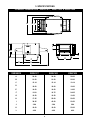
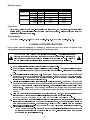
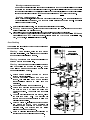
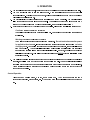
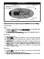
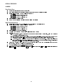
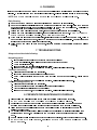
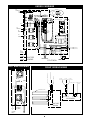
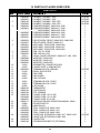
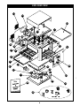
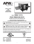
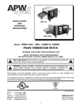
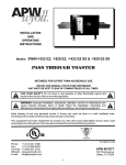
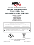
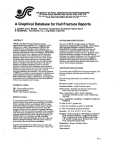
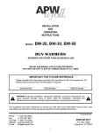
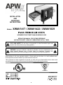
R INSTALLATION AND OPERATING INSTRUCTIONS Models: XWAV1417 / XWAV1422 / XWAV1829 PASS THROUGH OVEN INTENDED FOR OTHER THAN HOUSEHOLD USE RETAIN THIS MANUAL FOR FUTURE REFERENCE UNIT MUST BE KEPT CLEAR OF COMBUSTIBLES AT ALL TIMES ! FOR YOUR SAFETY: Do not store or use gasoline or other flammable vapors and liquids in the vicinity of this or any other appliance. ! ! WARNING: Improper installation, adjustment, alteration, service or maintenance can cause property damage, injury or death. Read the Installation, Operating and Maintenance Instructions thoroughly before installing or servicing this equipment. ! Initial heating of unit may generate smoke or fumes and must be done in a well ventilated area. Overexposure to smoke or fumes may cause nausea or dizziness. This equipment has been engineered to provide you with year-round dependable service when used according to the instructions in this manual and standard commercial kitchen practices. ANSI/NSF4 P/N 94000117 Phone: (214) 421-7366 Fax: (214) 565-0976 3/04 Toll Free: (800) 527-2100 APW WYOTT Website: www.apwwyott.com 729 Third Avenue E-mail: Dallas, TX 75226 [email protected] 1 TABLE OF CONTENTS SECTION 1 2 3 4 5 6 7 8 9 10 11 ITEM PAGE Owner's Information Safety Information Specifications Installation Instructions Operation Cleaning Troubleshooting Preventative Maintenance Schedule Wiring Diagrams Parts List and Exploded View Warranty 3 3 4 5 6 9 9 9 10 12 14 1. OWNER’S INFORMATION General Information: 1. 2. 3. Always clean equipment thoroughly before first use. (See general cleaning instructions). Check rating label for your model designation and electrical rating. For best results, use stainless steel countertops. General Operation Instructions: 1. 2. 3. All foodservice equipment should be operated by trained personnel. Do not allow your customers to come in contact with any surface labeled CAUTION HOT. Never touch ceramic or steel heaters. Warranty Information: Reliability Backed By APW Wyott’s Warranty: All APW Wyott Pass Through Ovens are backed by a one year parts and labor warranty, including On-Site Service calls within 50 miles of authorized service technicians. Service Information: Service Hotline (800) 733-2203 2. SAFETY INFORMATION APW Wyott equipment is designed, built and sold for commercial use and should be operated by trained personnel only. Clearly post all CAUTIONS, WARNINGS and OPERATING INSTRUCTIONS near each unit to insure proper operation and to reduce the chance of personal injury and/or equipment damage. This product is used for the cooking, defrosting or re-thermalization of food products only. Always disconnect power before servicing the unit. Surfaces will remain hot after power has been turned off. Allow unit to cool before cleaning or servicing. Never clean the unit by immersing it in water. The unit is not protected against water jets; DO NOT CLEAN PASS THROUGH OVEN WITH A WATER JET. Always clean equipment properly before first use. 2 3. SPECIFICATIONS OVERALL DIMENSIONS - XWAV1417, XWAV1422 & XWAV1829 A B C J DE G L K F H I DIMENSION XWAV1417 XWAV1422 XWAV1829 A 24.49 24.49 28.00 B 21.00 21.00 25.00 C 15.14 15.14 19.14 D 18.00 18.00 18.00 E 14.00 14.00 14.00 F 11.80 16.75 24.05 G 10.50 10.50 10.50 H 17.25 22.00 29.50 I 38.25 43.00 50.50 J 3.84 3.84 3.84 K 18.00 18.00 22.00 L 4.00 4.00 4.00 3 Electrical ratings: MODEL XWAV1417 XWAV1422 XWAV1829 WATTS VOLTS 4100 208 4100 240 5400 208 5400 240 7200 208 7200 240 AMPS (1 Phase) 19.7 17.1 26.0 22.5 34.6 30.0 NEMA PLUG 6-30P 6-30P 6-30P 6-30P 6-50P 6-50P Power Cord: Six (6) foot, 3 wire grounded cord. If the supply cord is damaged, the manufacturer, or an authorized service agent, must replace it in order to avoid a hazard and warranty. Please contact the factory by calling the 800 # located on the unit. Shipping Weight: XWAV1417 98 lbs. (44.5 kg.); XWAV1422 115 lbs. (52.2 kg.); XWAV1829 149 lbs. (67.6 kg.) 4. INSTALLATION INSTRUCTIONS If the carton appears damaged, or damage is discovered once the carton is opened, stop immediately and contact the freight company to file a damage claim. CAUTION: The Pass Through Oven is shipped assembled. The unit is shipped with ! urethane supports between the top heaters and the conveyor assembly. Please remove all urethane supports and packaging materials before operating the unit. Failure to remove all packaging materials may lead to a fire and / or damage to the appliance. ! 1. Remove all external packaging that is protecting top portion of unit. 2. Remove unit from shipping container while in the upright position. The unit can be lifted out of the carton by grasping under the conveyor on each side of the appliance. Please remove the plastic bag. 3. Remove all internal packaging to the unit. Important: Remove urethane supports located inside the tunnel oven between the top heaters and the conveyor. Remove tape from conveyor trays. Remove tape from extrusion corners. Remove tape from deflecting curtains located just above entrance and exit of conveyor. 4. Visually inspect all external and internal portions of unit for damage. Important: Inspect the top white ceramic elements located inside the oven tunnel after removal of urethane supports. To inspect these white ceramic elements, use a small mirror held under each element to detect cracks. Important: The Ceramic elements are fragile and will break under stress. Do not twist, pull, push, or otherwise subject the white ceramic elements to stress. 5. Wipe down the exterior of the unit using a damp cloth with warm water. Do not use abrasive pads or cleaners as they will damage the stainless steel surface and high temperature plastic. NOTE: DO NOT USE CLEANERS OFANY KIND ON THE WHITE CERAMIC HEATERS. 6. Remove four feet from box and install into threaded nuts located at the four corners underside of the left and right housings; Also remove conveyor extension tray(s). Conveyor extensions should be hung off end of conveyor frame. As our standard, Model XWAV1417 will only have one extension intended for the exit end; Model XWAV1422 and XWAV1829 will have two for loading and exit ends. 7. Place unit in operating location. Note: Ambient Conditions - Make sure that the operating location is in an area where the ambient temperature is held constant (minimum 70°F). Please avoid areas such as near exhaust fans and air conditioning ducts. 4 Warning: Operating environment Ensure that operation location is at a reasonable distance from combustible walls and materials otherwise combustion or discoloration could occur. Stand-off/Air-divider located on rear panel is important in maintaining proper division of inlet and exhaust air flow - If removed it could result in improper functioning of unit and MAY cause personal injury and WILL void your warranty. Caution: Operating environment Place unit on a stable, level counter at a convenient height for use. Turn the adjustable feet so that unit is level to countertop. The top of the unit is not intended for use a shelf. Materials placed there are at risk for fire. 8. Before plugging unit into wall, make sure that the switch is in the off position. 9. Warning: Ensure no hands, tools or parts or other unintended items are located on the conveyor as injury will result when unit is turned on. 10. Plug unit into grounded electrical outlet with correct voltage, and plug configuration. Warning: Using any receptacle that is not designed to match the attached cord and plug MAY cause personal injury and WILL void your warranty. Please attach the XWAV1422/Medium Size unit, 208V, 5400W only, to an individual branch circuit. Oven Stacking The stacking kit will consist of 4 corner posts to be inserted between stacked units. FIGURE 1 Remove End Caps & Screws Before Installing Kit When stacking, unit must have proper stacking kit installed. This will prevent overheating and damaging of electrical components. Warning: Warning: Do not stack more than three units tall or do not use more than two stacking kits. Warning: Standoff on rear panel of unit is important to allow proper inlet and exhaust fan airflow. Do not cover inlet or exhaust fan openings as this could damage electrical components. 1. Ensure bottom unit is mounted on secure surface, with feet installed. 2. Remove respective corner end caps and screws. This will allow each of the stacking spacer retaining fingers to slide into the extrusions. 3. Remove the feet from the top unit as shown. 4. Secure each stacking spacer to the bottom of the unit as shown by using the bolts and washers provided. You should have four total of each. 5. Once the stacking kit spacers are secure, place top unit onto bottom unit. The stacking kit spacers each have tapered guides to allow the unit to lock into position. 6. Refer to Figure 1. Install rear support bracket and screws as shown. Each stacking kit requires that two brackets be mounted on the backside only. One bracket near the strain relief and one at the opposite end. 7. Refer to Cleaning Instructions for cleaning of stacking spacers and cleaning between units. 5 Stacking Kit #94000189 5. OPERATION 1. The controls that operate the unit, heaters and conveyor are located on the front left side of the unit. 2. The On/Off switch is used to turn the unit on or off. Once the unit is turned on the conveyor will automatically run. Warning: Ensure no hands, tools or parts are located on the conveyor as injury will result when unit is turned on. 3. The control display (oval keypad) is used to control top and bottom heat only. The control settings allow for separate upper and lower zone control. The settings for upper and lower zones are 1 through 15; 1 being coolest and 15 being hottest setting. (See control operation below) 4. Note: Before moving the On / Off switch to the On position, please read the following statements: Caution: External Surface Temperatures The unit's external surface temperatures will be hot. Use caution when touching these areas to avoid injury. Warning: Severe Burns - Ceramic Heaters The white ceramic heaters operate at high temperatures. Do not touch elements after power is applied to the elements. Incorporated into the front surface of the element is a red color changing decal. As the element reaches a predetermined temperature, the decal will change from red to black. The decal will remain black until the element falls below the transition temperature where it will then return to its original red color. However, the element even if red will still be extremely hot. This color changing feature is used ONLY for determining if element is operating properly. 5. The deflector curtains located at the entrance and exit of the unit are used to contain the heat inside the unit, as well as keep any forced drafts from entering the unit. These curtains aid in efficient operation of the heaters and can be adjusted to increase or decrease the entrance and exit height. These curtains should be adjusted to the minimum height required above the conveyor for the product you are heating. Control Operation This oven has 3 heating zones, 2 on top, and a bottom one. The 2 top zones share the same parameters (set point, probe offsets, etc.) The bottom zone is completely independent of the top one. 6 USER INTERFACE Top Zone Selected Active Top Zone Active Bottom Zone Up Bottom Zone Selected Alarm Down Bottom Zone Top Zone There are 4 keys: Bottom Zone, Top Zone, Up, and Down. There are also 5 status LEDs: 2 that indicate the currently selected Zone; and 2 that indicate the zone Heater output state; and 1 for theAlarm conditions. OPERATING MODES DISPLAY · Set point temperature is displayed as a range: 1, 2, 3,..., 14, 15. 1 corresponds to the lowest sensor temperature and 15 corresponds to the highest sensor temperature. The factory default setting is 8. Once the settings are changed and the unit is turned off, these new settings will remain in memory and appear in the display once the unit is turned on. PREHEAT MODE · · · · · · Unit powers up in this state Unit displays Lo and the active bottom and active top LEDs are on whenever the corresponding zone output is active. A normal press of Bottom Zone key selects this zone (its LED lights up) and display shows its current set point for 5 seconds A normal press of Top Zone key selects this zone (its LED lights up) and display shows its current set point for 5 seconds Up and Down keys are used to change set point of current zone. Set point is displayed for 5 seconds after last Up or Down key press, then normal display resumes. Default set points are defined in Lowlevel parameters. Preheat state ends when both top and bottom zones are within the Low Temperature threshold defined in Low-level programming. READY MODE · · · Unit displays rdy and the active bottom and active top LEDs are on whenever the corresponding zone output is active. All keys work in the same fashion as for the Preheat mode Ready state ends when one of the top or bottom zones fall below the Low Temperature threshold defined in Low-level programming (unit then goes back to Preheat mode) 7 SPECIAL FEATURES ALARMS Zone Probe Error · · · · · Heater probe is disconnected or defective Normal user interface operation applies, but heater output remains inoperative Display flashesAlarm LED as well as anAlarm ID: o AL1 for Zone 1 (Bottom probe) o AL2 for Zone 2 (Top, probeA) o AL3 for Zone 3 (Top, probe B) Alarm shuts down all outputs Probe must be replaced or re-connected to allow normal use High Temperature Error · · · · · · · · Heater element is too hot, most likely due to external SSR that failed short Display flashesAlarm LED as well as anAlarm ID: o AL4 for Zone 1 (Bottom probe) o AL5 for Zone 2 (Top, probeA) o AL6 for Zone 3 (Top, probe B) Alarm shuts down heater regulation. The alarm threshold temperature is Low-level programmable Algorithm: o In normal use, if temperature ever goes above (set point + threshold), High Temperature Error is immediately triggered. o If set point is changed (lowered) by the user, the unit will look at the current temperature for 2 minutes and display HI. The peak temperature reached during this time is recorded. o Thereafter, unit monitors the temperature until it reaches set point. During this cooldown time, standard HI message is still displayed. User may change set point again, but 2-minute timer is not restarted (and old Peak value still applies.) During the cooldown time, if ever the temperature rises above the previously recorded peak temperature, High Temperature Error is triggered. Once set point is reached, rdy is displayed again. HI is displayed only if other zone is rdy or also HI. If other zone is Lo, then LH (low-high) is displayed instead of HI. 8 6. CLEANING Insure the appliance has been turned off and has had sufficient time for all surfaces to cool down before cleaning. Use only mild soap and water to clean this appliance.Appliance cleaning should be performed daily. NOTE: DO NOT USEABRASIVE PADS OR CLEANING SOLUTIONS ON THISAPPLIANCE. Daily Cleaning Remove the crumb pans and wipe out debris with a damp rag and mild soap solution. Remove the deflector panels located at the entrance and exit of the oven tunnel. Wipe down the area under the deflector panels, and the deflector panels, with a damp rag and mild soap. Reinstall the deflector panels by reversing the procedure used to remove them. Using a damp rag with mild soap and water, wipe down the exterior surfaces of the appliance. Using a damp rag with mild soap solution, wipe down all areas of the conveyor. DO NOT ATTEMPT TO CLEAN THE UPPER WHITE CERAMIC, OR LOWER METAL HEATERS. When units are in the stacked configuration, it is still necessary to clean between the units. Using a damp rag with mild soap and water, wipe down the tops and undersides of all units. Ensure there are no foreign objects between the units that could catch fire. Using a damp rag with mild soap and water, wipe the surfaces of the stacking spacers on all four corners. 7. TROUBLESHOOTING Always ask and check the following: Not getting power: 1. 2. 3. 4. 5. Is the unit connected to a live power source of the proper voltage? Check the rating label. Is the unit connected to the correct power source? Check the circuit breaker. Is power switch ON and led displaying information? If the above checks out, and you still have problems, call your local service agent. Conveyor not working: 1. Please refer to Not getting power section. 2. Is the knob turned to correct setting per desired speed? 3. Note: At slower settings the conveyor moves very slow and may appear stalled, which is not the case. 4. If the above checks out, and you still have problems, call your local service agent. Food not cooking properly: 1. 2. 3. 4. Please refer to Not getting power section. Are the controller and speed control adjusted to the desired setting? Are the deflector curtains in the proper position? If the above checks out, and you still have problems, call your local service agent. 8. PREVENTATIVE MAINTENANCE SCHEDULE Please follow the cleaning section for the daily preventative maintenance schedule. DO NOT USE ABRASIVES OR CLEANING SOLUTIONS ON THIS APPLIANCE. Routinely check before every operation that adequate distance is allowed between fans and anything that would possibly allow foreign debris or substances to be taken in by inlet fan. Clean fan guards on a daily basis to ensure proper inlet cooling to electrical components and efficient hot air exhaust. On a daily basis make sure side walls of tunnel oven remain clean to assist in maintaining even cooking around product. Be careful not to bump or hit the upper ceramic heaters when wiping down. Ensure belt is properly tensioned as to prevent slippage or binding, which causes strain on motor. DO NOTATTEMPT TO MAINTENANCE, SERVICE OR CLEAN THE UPPER CERAMIC AND LOWER METAL HEATERS. 9 9. WIRING DIAGRAMS OVERHEAD (XWAV1417) REAR HEATER ZONE 3 RTD3 TO: CONTROLLER RTD 3 10 15 TO: TERM BLK TO: TERM BLK 9 TO: RELAY 15 9 10 9 10 RTD 2 RTD2 TO: CONTROLLER 15 12 11 15 16 12 11 16 16 TO: RELAY RTD 2 FRONT HEATER ZONE 2 OVERHEAD (XWAV1422) RTD 3 TO: CONTROLLER AN3 RTD 3 11 11 10 12 12 9 REAR HEATERS ZONE 3 10 9 RTD 2 TO: TERMINAL BLOCK TO: RELAY RTD 2 TO: CONTROLLER AN2 13 13 15 14 14 16 16 15 TO: TERMINAL BLOCK 16 TO: RELAY FRONT HEATERS ZONE 2 OVERHEAD (XWAV1829) RTD 3 TO: CONTROLLER AN3 RTD 3 11 11 10 12 12 9 REAR HEATERS ZONE 3 13 14 13 RTD 2 FRONT HEATERS ZONE 2 10 TO: TERMINAL BLOCK RTD 2 TO: CONTROLLER AN2 15 14 10 16 15 9 TO: RELAY TO: TERMINAL BLOCK 16 TO: RELAY UNDER CARRIAGE TO TERM BLK TO TERM BLK RTD 3 RTD 2 RTD 1 7 7 21 25 22 20 RTD 2 RTD 1 6 ZONE 3 T1 9 RTD 1 15 + (P11 "-") (P15 "+") 19 20 (P16 "-") (P20 "+") 17 18 22 25 A1 L1 -A2 8 21 22 6 21 WHITE (-) AN1 AN2 30 WHT SEE DETAIL VIEW 3 TO TERM BLK 16 8 ZONE 2 T1 A1 20 L1 - A2 19 + ZONE 1 RTD 1 3 RED 31 SCOTCHLOCK 3 18 L1 - A2 17 OR BLUE GREEN ORANGE GR BL 31 3 7 7 24 A1 MOTOR 29 4 28 TO: TERMINAL BLK L1 TO: TERMINAL BLK L2 5 T1/2 1/L1 24 T2/4 3/L2 32 T3/6 5/L3 BLK 14 13/NO 28 22 21/NC 23 2 RED OR 14 RIGHT SIDE HOUSING GR BL 29 MOTOR SPEED POT. ESCUTCHEON 30 POWER SWITCH RIGHT SIDE HOUSING CONTROLLER TO T.STAT TO RELAY 13 LEFT SIDE HOUSING 1 CONTACTOR A2 32 TO: TEMP PROBE RTD1 TO: ELEMENT TO: ELEMENT BLK BLACK WHITE RED 24 A1 + 4 RED/BROWN BLACK/BLUE 23 SCOTCHLOCK 7 14 T1 RED (+) BLACK (-) TO TERMINAL BLOCK TO TERM BLK TO TERM BLK 18 17 (P6 "-") (P9 "+") AN3 M. CTL. 3 14 24 I/O 1 I/O 2 I/O 3 7 L2/N L1 L1 L2 6 RTD 3 15 TO SPEED TO SPEED TO SPEED MOTOR-ORANGE MOTOR-GREEN MOTOR-BLUE TO CONTACTOR "A2" L2 1 L2 RTD 1 2 26 5 L1 L1 LOWER HEATER ZONE 1 BL GR 29 T.STAT GR RIGHT SIDE HOUSING 26 POWER CORD L1= BLACK L2= WHITE TO: POWER SWITCH 11 30 POWER SWITCH ESCUTCHEON 2 5 OR MOTOR SPEED POT. L1 L2 2 TO POWER SUPPLY 6 PIN-RED 10. PARTS LIST & EXPLODED VIEW ITEM 1 2 3 4 5 6 7 8 9 10 11 12 13 14 15 16 17 18 19 20 21 22 23 24 25 26 27 28 29 30 PARTS LIST PART NUMBER DESCRIPTION 94000028 94300001 94000128 94300002 94000032 94100016 94200012 94300003 94400001 94500001 94000024 94100015 94000041 94100022 94200021 93000067 93000070 82914 94000098 94100043 94200045 39104 39102 95000033 69148 85283 85287 85284 30201 30203 86295 94000105 94000106 94000108 94000109 94100048 94200057 94000117 89488 88705 94000056 94100029 94200029 94100045 94200055 94100108 94000189 ELEMENT, CERAMIC, 208V ELEMENT, CERAMIC, 240V ELEMENT, CERAMIC, 208V, RTD ELEMENT, CERAMIC, 240V, RTD FIREBAR ELEMENT, XWAV1422, 208V FIREBAR ELEMENT, XWAV1417, 208V FIREBAR ELEMENT, XWAV1829, 208V FIREBAR ELEMENT, XWAV1422, 240V FIREBAR ELEMENT, XWAV1417, 240V FIREBAR ELEMENT, XWAV1829, 240V ESCUTCHEON, FRONT, XWAV1422, XWAV1829 ESCUTCHEON, FRONT, XWAV1417 WELD ASSY, CONVEYOR, XWAV1422 WELD ASSY, CONVEYOR, XWAV1417 WELD ASSY, CONVEYOR, XWAV1829 END, CAP, F/L & B/R END CAP, B/L & F/R CHAIN, CONVEYOR DRIVE, XWAV1417, 1422, 1829 WIRE BELT, XWAV1422 WIRE BELT, XWAV1417 WIRE BELT, XWAV1829 GEARMOTOR, CONVEYOR OVEN POWER SUPPLY, GEAR MOTOR TERMINAL BLOCK, CERAMIC RELAY, SOLID STATE FAN CORD FAN GUARD FAN,COOLING TERMINAL BLOCK, 3 POLE TERMINAL BLOCK, 2 POLE LEG, BLACK THERMOSTAT CONTROLLER RTD, FIREBAR POWER CORD, 10/3, 6-30P POWER CORD, 12/3, 6-30P POWER CORD, 8/3, 6-50P INSTALLATION AND OPERATION MANUAL, XWAV ROCKER SWITCH KNOB, BLACK TRAY, CONVEYOR, XWAV 1422 TRAY, CONVEYOR, XWAV 1417 TRAY, CONVEYOR, XWAV 1829 CONVEYOR, EXTENSION, XWAV 1417, XWAV 1422 CONVEYOR, EXTENSION, XWAV 1829 CONTACTOR STACKING BRACKET KIT (OPTIONAL) 12 QUANTITY AS R'QD AS R'QD AS R'QD AS R'QD 1 1 1 1 1 1 1 1 1 1 1 4 4 1 1 1 1 1 1 AS R'QD 3 2 2 2 1 1 4 2 1 1 1 1 1 1 1 1 2 2 2 AS R'QD 2 1 1 EXPLODED VIEW 15 14 28 8 1 6 20 12 23 7 3 16 18 4 2 9 22 5 10 27 26 21 13 17 11 XWAV 25 29 24 30 Stacking Kit 13 19 11. APW WYOTT EQUIPMENT LIMITED WARRANTY APW Wyott Foodservice Equipment Company warrants it's equipment against defects in materials and workmanship, subject to the following: This warranty applies to the original owner only and is not assignable. Should product fail to function in its intended manner under normal use within the limits defined in this warranty, at the option ofAPW Wyott such product will be repaired or replaced byAPWWyott or itsAuthorized ServiceAgency.APWWyott will only be responsible for charges incurred or service performed by its Authorized Service Agencies. The use of other than APW Wyott Authorized Service Agencies will void this warranty and APW Wyott will not be responsible for such work or any charges associated with same. The closestAPWWyottAuthorized ServiceAgent must be used. This warranty covers products shipped into the 48 contiguous United States, Hawaii, metropolitan areas ofAlaska and Canada. There will be no labor coverage for equipment located on any island not connected by roadway to the mainland. Time Period One year parts, one year labor, effective from the date of purchase by the original owner. TheAuthorized Service Agency may, at their option, require proof of purchase. Parts replaced under this warranty are warranted for the un-expired portion of the original product warranty only. Exceptions *Gas/Electric Cookline Models GCB, GCRB, GF, GGM, GGT, GHP-H, EF, EG, EHP Three (3) Year Warranty on all component parts, except switches and thermostats. (2 additional years on parts only.No labor on second or third year.) *Heat Strips Models OH & FD Two (2)YearWarranty on element only No labor second year. *Glass Windows, Door Seals, Rubber Seals, Light Bulbs, Broiler Briquettes 90 Day Material Only No Labor. In all cases, parts covered by extended warranty will be shipped FOB the factory after the first year. Portable Carry In Products Equipment weighing over 70 pounds or permanently installed will be serviced on-site as per the terms of this warranty. Equipment weighing 70 pounds or under, and which is not permanently installed, i.e. with cord and plug, is considered portable and is subject to the following warranty handling limitations. If portable equipment fails to operate in its intended manner on the first day of connection, or use, atAPWWyott's option or itsAuthorized ServiceAgency,it will be serviced on site or replaced. From day two through the conclusion of this warranty, portable units must be taken to or sent prepaid to the APW Wyott Authorized Service Agency for in-warranty repairs. No mileage or travel charges are allowed on portable units after the first day of use. If the customer wants on-site service, they may receive same by paying the travel and mileage charges. Exceptions to this rule: (1) countertop warmers and cookers, which are covered under the Enhanced Warranty Program, and (2) toasters or rollergrills which have in store service. Exclusions The following conditions are not covered by warranty: *Equipment failure relating to improper installation, improper utility connection or supply and problems due to ventilation. *Equipment that has not been properly maintained, calibration of controls, adjustments, damage from improper cleaning and water damage to controls. *Equipment that has not been used in an appropriate manner, or has been subject to misuse misapplication, neglect, abuse, accident, alteration, negligence, damage during transit, delivery or installation, fire, flood, riot or act of god. *Equipment that has the model number or serial number removed or altered. If the equipment has been changed, altered, modified or repaired by other than a qualified service technician during or after the warranty period, then the manufacturer shall not be liable for any damages to any person or to any property, which may result from the use of the equipment thereafter. This warranty does not cover services performed at overtime or premium labor rates. Should service be required at times which normally involve overtime or premium labor rates, the owner shall be charged for the difference between normal service rates and such premium rates.APWWyott does not assume any liability for extended delays in replacing or repairing any items beyond its control. In all cases the use of other thanAPWWyottAuthorized OEM Replacement Parts will void this warranty. This equipment is intended for commercial use only.Warranty is void if equipment is installed in other than commercial application. Water Quality Requirements Water supply intended for a unit that has in excess of 3.0 grains of hardness per gallon (GPG) must be treated or softened before being used. Water containing over 3.0 GPG will decrease the efficiency and reduce the operation life of the unit. Note: Product failure caused by liming or sediment buildup is not covered under warranty. THE FOREGOING WARRANTY IS IN LIEU OF ANY AND ALL OTHER WARRANTIES EXPRESSED OR IMPLIED INCLUDING ANY IMPLIED WARRANTY OR MERCHTABILITY OR FITNESS FOR PARTICLUAR PURPOSES AND CONSTITUTES THE ENTIRE LIABILITY OF APW WYOTT. IN NO EVENT DOES THE LIMITED WARRANTY EXTEND BEYOND THE TERMS HEREIN. 14 IMPORTANT FOR FUTURE REFERENCE Please complete this information and retain this manual for the life of the equipment. For Warranty Service and/or Parts, this information is required. Model Number Serial Number Notes: 15 Date Purchased Phone: (214) 421-7366 Fax: (214) 565-0976 Toll Free: (800) 527-2100 APW WYOTT Website: www.apwwyott.com 729 Third Avenue E-mail: Dallas, TX 75226 [email protected] 16