1
PREMIERLINK™
Retrofit Rooftop Controller
Version 3.x
Installation, Start-Up and
Configuration Instructions
Part Number 33CSPREMLK
CONTENTS
Page
SAFETY CONSIDERATIONS . . . . . . . . . . . . . . . . . . . . . . 1
GENERAL . . . . . . . . . . . . . . . . . . . . . . . . . . . . . . . . . . . . . . . . 2
INSTALLATION . . . . . . . . . . . . . . . . . . . . . . . . . . . . . . . . 2-30
Inspection. . . . . . . . . . . . . . . . . . . . . . . . . . . . . . . . . . . . . . . . 2
PremierLink Controller Hardware. . . . . . . . . . . . . . . . . 2
Field-Supplied Hardware . . . . . . . . . . . . . . . . . . . . . . . . . 2
• SPACE TEMPERATURE (SPT) SENSOR
• SUPPLY AIR TEMPERATURE (SAT) SENSOR
• INDOOR AIR QUALITY CO2 SENSOR
• OUTDOOR AIR QUALITY CO2 SENSOR
• RELATIVE HUMIDITY SENSOR
• OUTDOOR AIR TEMPERATURE SENSOR
• OUTDOOR AIR ENTHALPY SWITCH/RECEIVER
• FILTER SWITCH
Mount PremierLink Control. . . . . . . . . . . . . . . . . . . . . . . 3
• LOCATION
• MOUNTING
PremierLink Controller Inputs and Outputs . . . . . . 3
Control Wiring. . . . . . . . . . . . . . . . . . . . . . . . . . . . . . . . . . . 10
Install Sensors . . . . . . . . . . . . . . . . . . . . . . . . . . . . . . . . . . 10
• SPACE TEMPERATURE (SPT) SENSOR
INSTALLATION
• SUPPLY AIR TEMPERATURE (SAT) SENSOR
INSTALLATION
• INDOOR AIR QUALITY CO2 SENSOR
INSTALLATION
• OUTDOOR AIR QUALITY CO2 SENSOR
INSTALLATION
• HUMIDITY SENSOR (WALL-MOUNTED) INSTALLATION
• OUTDOOR AIR TEMPERATURE SENSOR
• FACTORY-INSTALLED CONTROLLER
Connect Discrete Inputs . . . . . . . . . . . . . . . . . . . . . . . . 19
Connect to CCN Communication Bus . . . . . . . . . . . 19
• COMMUNICATIONS BUS WIRE SPECIFICATIONS
Enthalpy/Switch Receiver . . . . . . . . . . . . . . . . . . . . . . . 23
• OUTDOOR ENTHALPY CONTROL
• DIFFERENTIAL ENTHALPY CONTROL
Enthalpy Sensors and Control . . . . . . . . . . . . . . . . . . 25
• OUTDOOR AIR ENTHALPY SENSOR/
ENTHALPY CONTROLLER
• RETURN AIR ENTHALPY SENSOR
Economizer . . . . . . . . . . . . . . . . . . . . . . . . . . . . . . . . . . . . . 26
• Q769B ADAPTER
• Q769C ADAPTER
Economizer with 4 to 20 mA Actuator . . . . . . . . . . . 28
• DRIVE DIRECTION
• SWITCH SELECTION
• WIRING
START-UP . . . . . . . . . . . . . . . . . . . . . . . . . . . . . . . . . . . . 30-37
Page
Perform System Check-Out . . . . . . . . . . . . . . . . . . . . . 30
Initial Operation and Test . . . . . . . . . . . . . . . . . . . . . . . 30
Sequence of Operation. . . . . . . . . . . . . . . . . . . . . . . . . . 30
• THERMOSTAT MODE
• CCN SENSOR MODE
Alarms . . . . . . . . . . . . . . . . . . . . . . . . . . . . . . . . . . . . . . . . . . 36
CONFIGURATION . . . . . . . . . . . . . . . . . . . . . . . . . . . . 37-55
Points Display Screen. . . . . . . . . . . . . . . . . . . . . . . . . . . 37
Thermostat Control Input Screen. . . . . . . . . . . . . . . . 40
Alarm Service Configuration Screen . . . . . . . . . . . . 40
Controller Identification Screen . . . . . . . . . . . . . . . . . 41
Holiday Configuration Screen . . . . . . . . . . . . . . . . . . . 41
Occupancy Configuration Screen . . . . . . . . . . . . . . . 41
Set Point Screen . . . . . . . . . . . . . . . . . . . . . . . . . . . . . . . . 42
Service Configuration Selection Screen. . . . . . . . . 43
PremierLink Configuration Screen . . . . . . . . . . . . . . 47
Occupancy Maintenance Screen . . . . . . . . . . . . . . . . 49
Primary Maintenance Screen. . . . . . . . . . . . . . . . . . . . 50
System Pilot™ Maintenance Table . . . . . . . . . . . . . . 53
System Pilot Alternate Maintenance Table. . . . . . . 54
APPENDIX A — CCN SCREENS . . . . . . . . . . . . . . 56-59
SAFETY CONSIDERATIONS
SAFETY NOTE
Air-conditioning equipment will provide safe and reliable
service when operated within design specifications. The
equipment should be operated and serviced only by authorized personnel who have a thorough knowledge of system
operation, safety devices and emergency procedures.
Good judgement should be used in applying any manufacturer’s instructions to avoid injury to personnel or damage to
equipment and property.
WARNING
Disconnect all power to the unit before performing maintenance or service. Unit may automatically start if power is
not disconnected. Electrical shock and personal injury
could result.
CAUTION
An individual field-supplied 24-vac power transformer is
recommended for each PremierLink controller. If the unit
transformer is used but does not have enough power, damage to equipment may result. The field-supplied transformer must be less than 100 VA to meet UL (Underwriters
Laboratories) Class 2.
Manufacturer reserves the right to discontinue, or change at any time, specifications or designs without notice and without incurring obligations.
Catalog No. 04-53330016-01
Printed in U.S.A.
Form 33CS-68SI
Pg 1
5-11
Replaces: 33CS-67SI
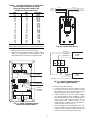
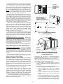
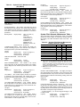
SPACE TEMPERATURE (SPT) SENSOR — A fieldsupplied Carrier space temperature sensor is required to maintain
space temperature in sensor mode. There are four sensors available for this application:
• 33ZCT55SPT, space temperature sensor with override
button
• 33ZCT56SPT, space temperature sensor with override
button and set point adjustment
• 33ZCT59SPT, space temperature sensor with LCD (liquid
crystal display) screen, override button, and set point
adjustment
• 33PILOT-01, System Pilot communicating room sensor
with LCD display screen, override button, setpoint adjustment, temperature and setpoint display and system time
clock
If controlling an economizer in the thermostat mode, a duct
sensor must be mounted in the return air duct and wired to SPT
input.
SUPPLY AIR TEMPERATURE (SAT) SENSOR — The
PremierLink controller must be connected to a field-supplied
supply air temperature (SAT) sensor (part number
33ZCSENSAT) to monitor the temperature of the air delivered.
The SAT consists of a thermistor encased within a stainless
steel probe. The probe is 6 in. nominal length. The SAT sensor
has 114 in. of unshielded, plenum-rated cable (2 conductors,
22 AWG [American Wire Gage]). The sensor range is –40 to
185 F with a nominal resistance of 10,000 ohms at 77 F. The
sensor measures temperature with an accuracy of ±0.36 F.
Ideally, the SAT sensor should be located inside the unit
under the heat exchanger. The SAT sensor can also be installed
in the supply air duct downstream from unit heat source to
control.
INDOOR AIR QUALITY CO2 SENSOR — An indoor air
quality sensor is required for CO2 level monitoring. Three
different CO2 sensors are available for this application:
• 33ZCSENCO2 sensor is an indoor, wall-mounted sensor
with an LCD (liquid-crystal display) screen
• 33ZCT55CO2 sensor is an indoor, wall-mounted sensor
without display. The CO2 sensor also includes a space temperature sensor with override button
• 33ZCT56CO2 sensor is an indoor, wall-mounted sensor
without display. The CO2 sensor also includes a space temperature sensor with override button and temperature offset
OUTDOOR AIR QUALITY CO2 SENSOR — The
outdoor air CO2 sensor (33ZCSENCO2) is designed to monitor carbon dioxide (CO2) levels found in diesel exhaust and
control ventilation systems. It comes with an outdoor enclosure. This sensor provides an outdoor baseline for differential
DCV (demand controlled ventilation) control.
NOTE: The relative humidity sensor and the outdoor air CO2
sensor cannot both be used on the controller at the same time.
RELATIVE HUMIDITY SENSOR — The 33ZCSENSRH01 relative space humidity sensor is required for dehumidification control on a rooftop unit equipped with a dehumidification
device. Otherwise, the relative humidity sensor is used for
monitoring only.
NOTE: The relative humidity sensor and the outdoor air CO2
sensor cannot both be used on the controller at the same time.
OUTDOOR AIR TEMPERATURE SENSOR — The
outdoor air temperature sensor (33ZCSENOAT) monitors the
temperature of the outside air. If the sensor is to be installed in
the outdoor air duct instead of an outdoor location, sensor
33ZCSENPAT should be used.
OUTDOOR AIR ENTHALPY SWITCH/RECEIVER
(33CSENTHSW) — This device measures both temperature
and humidity and converts the data into a relay output dependent on the sensor mode. Mode 1 is designed to energize the
relay at a fixed set point of 28 Btu/lb or 75 F. Mode 2 is used in
GENERAL
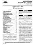
The PremierLink™ controller, version 3.x, is a field retrofit
rooftop control compatible with the Carrier Comfort Network®
(CCN) system. This control is designed to allow users the access and ability to change factory-defined settings, thus expanding the function of the standard unit control board. The
complete PremierLink package (part number 33CSPREMLK)
consists of a rooftop control circuit board with plastic cover
and label, wire harnesses, spade connectors, wire nuts and 4
mounting screws.
IMPORTANT: PremierLink part number 33CSPREMLK
should only be used in applications where the integrity
of the Underwriters Laboratories rating will be
maintained.
Access is available via an RJ-11 connection or a 3-wire connection to the communication bus. User interfaces available for
use with the CCN system are PCs equipped with Carrier user
interface software such as Service Tool, ComfortVIEW™, or
ComfortWORKS® software. When used as part of the CCN
system, other devices such as the CCN data transfer, System
Pilot™, Touch Pilot™, or Comfort Controller can read data
from or write data to the PremierLink retrofit controller. The
PremierLink controller default address is 0,31.
The PremierLink controller is available as a factoryinstalled option on some units. Additional terminal board(s) are
provided for field wiring. Sensors and input devices added in
the field should be wired to the terminal board(s) instead of directly to the PremierLink controller. Refer to the unit installation and service manuals for terminal locations and details. For
typical factory wiring details, see Factory-Installed Controller
section on page 19. Refer to unit’s label wiring diagram for
specific unit wiring.
INSTALLATION
Inspection — Inspect package contents for visual defects
that may have occurred during shipping. If there is any damage, contact your local representative before proceeding.
PremierLink Controller Hardware — The PremierLink package consists of the following hardware:
• control module (with plastic cover and label)
• 7 wire harnesses
• 10 spade connectors
• wire nuts
• 4 no. 6x1-in. self-drilling Phillips pan head mounting
screws
Field-Supplied Hardware — The PremierLink controller is configurable with the following field-supplied
sensors:
• space temperature sensor (33ZCT55SPT, 33ZCT56SPT,
33ZCT59SPT, or 33PILOT-01) in sensor mode or thermostat mode for economizer control
• supply air temperature sensor (33ZCSENSAT) required for
all applications
• indoor air quality sensor (33ZCSENCO2, 33ZCT55CO2,
33ZCT56CO2) required only for demand control
ventilation. A dedicated 24-vac transformer is required.
• outdoor air quality sensor (33ZCTSENCO2) required only
for demand control ventilation
• outdoor air temperature sensor (33ZCSENOAT)
• outdoor air enthalpy switch (33CSENTHSW)
• filter switch (third party differential airflow)
• return air enthalpy sensor (33CSENTSEN)
• indoor relative humidity sensor (33ZCSENSRH-01),
required only for dehumidification
For specific details about sensors, refer to the literature
supplied with the sensor.
2
2. Locate a space in the unit control panel or a space inside
the equipment that is free from dirt and dust.
3. Remove plastic cover by gently squeezing the middle of
longer sides of the cover and pull away from the board.
This will release the locking tabs inside.
4. Mount the PremierLink controller to the desired location
by holding the controller firmly in place. Be sure all
standoffs are in contact with mounting surface and board
DOES NOT flex. Attach controller to unit using 4 screws
provided ensuring a secure grip to unit surface.
See Fig.1.
NOTE: If PremierLink controller will be installed in same
location where Apollo controller was previously installed,
simply use 2 of the existing Apollo mounting holes to line up
with the board.
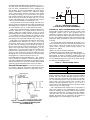
5. Provide 24 v power to the circuit board from the unit
transformer or an isolated power transformer. Use the
appropriate conductors for voltage per base unit nameplate. See Fig. 2-7. Board will require 10 va at 24 vac.
6. Replace plastic cover to protect circuit board.
7. Restore power to unit.
conjunction with the return air enthalpy sensor
(33CSENTSEN) to measure both indoor and outdoor enthalpy
and to determine which is greater. The enthalpy switch output
can be normally open or normally closed.
FILTER SWITCH — A field-supplied third-party differential
air flow switch with normally open contacts is requried for detection of dirty filters. The switch must be rated for a minimum
of 5 va at 24 vac.
Mount PremierLink™ Control
LOCATION — The PremierLink controller should be
located inside one of the available service access panels of the
unit. Be sure the location selected prevents moisture and
rain from coming into contact with the circuit board.
IMPORTANT: Do not install in indoor fan section of unit.
Select a location which will be safe from water damage and
allow sufficient access for service and wiring. For service
access, there should be at least 6 in. of clearance between the
front of the PremierLink controller and adjacent surfaces. Be
sure to leave 1/2-in. clearance in front of RJ-14 connector for
attaching RJ-14 cable from a CCN interface device. A fieldsupplied right angle 6-pin RJ-14 connector can be attached if
necessary.
NOTE: If the PremierLink controller must be installed in a
location where there is not easy access to CCN connectors,
a remote connection kit (part number 33CSREMCCN) can
be ordered.
MOUNTING — Refer to Mounting Sheet included with
controller for additional detailed mounting instructions.
1. Ensure all power to unit is removed.
a33-9209
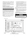
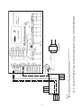
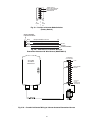
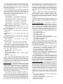
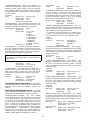
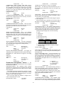
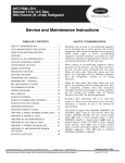
PremierLink Controller Inputs and Outputs —
The PremierLink controller inputs and outputs are shown in
Table 1.
WARNING
Disconnect electrical power before wiring the PremierLink controller. Electrical shock, personal injury, or
damage to the PremierLink controller can result.
Fig. 1 — PremierLink Control Module
3
PWR
HS3/EXH/RVS
RED
R
ORN
Y1
RED
PNK
Y2
RED
W1
RELAYS
HS1
WHT
G
CMP2
BLU
C
RED
X
YEL
48HJ,TJ004-014
50HJ,TJ004-014
50HJQ,TJQ004-012
ROOFTOP UNIT
FAN
PWR
J1
J8
RED
GRN
BRN
GRN
RMTOCC
RED
YEL
CMPSAFE
BLU
RED
FSD
WHT
RED
PNK
RED
ORN
RED
SFS
DISCRETE
CMP1
DDC CONTROL
W2
J4
CUT FOR DUAL
TRANSFORMER
EQUIPMENT
HS2
CUT TO
ISOLATE
CONTROLLER
POWER
a33-9130
FILTER
ENTH
48/50HJ,TJ004-014 AND 50HJQ,TJQ004-012 UNITS
PWR
HS3/EXH/RVS
RED
TB2
W1
RED
PNK
R
RED
C
RELAYS
HS1
WHT
Y1
Y2
CMP2
BLU
G
RED
X
YEL
48HJ015-025
50HJ015-025
48TJ016-028
50TJ016-028
ROOFTOP UNIT
PWR
J1
J8
RED
FAN
GRN
BRN
GRN
RMTOCC
RED
YEL
CMPSAFE
BLU
RED
WHT
RED
PNK
RED
ORN
RED
FSD
SFS
FILTER
ENTH
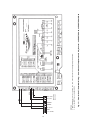
48/50HJ015-025 AND 48/50TJ016-028 UNITS
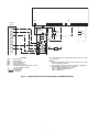
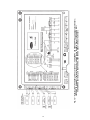
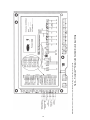
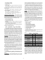
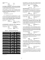
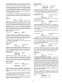
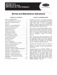
NOTE: Inputs on J4 are 24 VAC; red leads are voltage source.
Fig. 2 — Typical PremierLink™ Control Wiring to 48/50HJ,TJ, 50HJQ,TJQ Rooftop Units
4
DISCRETE
CMP1
DDC CONTROL
J4
CUT FOR DUAL
TRANSFORMER
EQUIPMENT
HS2
CUT TO
ISOLATE
CONTROLLER
POWER
a33-9131
W2
ORN
HS3/EXH/RVS
RED
RC
ORN
a33-9132
RH
RED
RED
HS2
PNK
W1
W2
RELAYS
HS1
WHT
DDC CONTROL
Y1
GRN
RMTOCC
RED
YEL
CMPSAFE
Y2
CMP2
BLU
G
RED
RED
J8
FAN
C
YEL
BLU
RED
X
WHT
RED
PNK
RED
ORN
RED
11
GRN
50HJQ014,016
PWR
J1
FSD
BRN
SFS
DISCRETE
CMP1
CUT TO
ISOLATE
CONTROLLER
POWER
TB2
J4
CUT FOR DUAL CAP OR REMOVE
TRANSFORMER THIS END OF
JUMPER
EQUIPMENT
PWR
FILTER
ENTH
50HJQ014,016 UNITS
NOTE: Inputs are 24 VAC; red leads are voltage source.
Fig. 2 — Typical PremierLink™ Control Wiring to 48/50HJ,TJ, 50HJQ,TJQ Rooftop Units (cont)
DDC CONTROL
HS3/EXH/RVS
RED
ORN
RED
BLU
RED
C
HS1
G
WHT
W2
CMP2
W1
BLU
RED
Y2
CMP1
YEL
Y1
T
H
E
R
M
O
S
T
A
T
WHT
RED
PNK
RED
ORN
RED
FSD
SFS
FILTER
ENTH
J8
RED
PWR
J1
CUT TO
ISOLATE
CONTROLLER
POWER
X
RED
RELAYS
CUT FOR DUAL
TRANSFORMER
EQUIPMENT
PNK
GRN
RMTOCC
RED
YEL
CMPSAFE
FAN
R
GRN
BRN
a33-9210
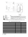
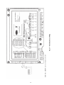
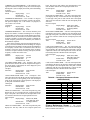
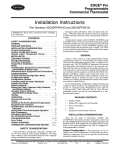
NOTE: Inputs are 24 VAC; red leads are voltage source.
Fig. 3 — Typical PremierLink™ Control Wiring to 48/50HC,TC, 50HCQ,TCQ Rooftop Units
5
DISCRETE
HS2
CENTRAL
TERMINAL
BOARD
J4
PWR
(24 v)
CB
EQUIP
GND
IFC
LLSV
NEC
TB
—
—
—
—
—
—
—
LEGEND
Circuit Breaker
Equipment
Ground
Indoor Fan Contactor
Liquid Line Solenoid Valve
National Electrical Code
Terminal Block
Field Control Wiring
Factory Wiring
Field Power Wiring
(115 v)
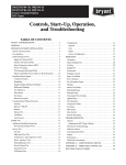
*Use thermostat wiring shown here for single air-handler applications.
†CB3 protects control circuit at the following unit voltages:
CONTROL CIRCUIT PROTECTED AT:
(V-Ph-Hz)
115-1-60
a387050.eps
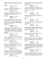
NOTES:
1. CB4 protects TB2 circuit; CB3 protects TB3 circuits.
2. LLSV1 and LLSV2 are field supplied.
3. TB2 is 24 v and TB3 is 115 v.
230-1-60
UNIT (V-Ph-Hz)
208/230-3-60
460-3-60
575-3-60
380-3-60
**For a single air handler, LLSV valve 1 is to be used on the lower
(no. 1) evaporator circuit. The LLSV valve 2 is to be used on the
upper (no. 2) evaporator circuit.
††Only one indoor-fan contactor is required on single air-handler applications. Use Carrier accessory part no. 40RR900181 for indoor-fan
contactor.
Fig. 4 — Typical PremierLink™ Control Wiring to 38AH024-034 Units with Single Air Handler
6
IFC†
1
FAN
COOL
1
CKT 1
TSTAT
COOL
2
CCS
1
R
CB3*
CB4
+
+
C
CKT 2
TSTAT
TB2
10 10
9
9
8
8
7
7
6
6
5
5
4
4
3
3
2
2
1
1
(24 v)
IFC†
2
FAN
COOL
1
COOL
2
CCS
2
**
R
C
CB
CCS
IFC
LEGEND
— Circuit Breaker
— Capacity Control Solenoid
— Indoor-Fan Contactor
Field Control Wiring
*CB3 protects control circuit as follows:
CONTROL CIRCUIT PROTECTED AT:
(V-Ph-Hz)
115-1-60
230-1-60
a38-7051
UNIT (V-Ph-Hz)
208/230-3-60
460-3-60
575-3-60
380-3-60
†Use Carrier accessory part no. 40RR900181 for indoor-fan contactor.
**Do not install CCS2 unless accessory unloader is field-installed on
circuit no. 2 compressor.
NOTE: Capacity control solenoid (and liquid line solenoid drop refrigerant control) valves are field supplied.
Fig. 5 — Typical PremierLink™ Control Wiring to 38AH024-034 Units with 2 Air Handlers
7
TB4
TB3
TSTAT
24 vac
3
2
1
4
5
6
7
8
1
2
3
4
5
6
7
8
R
R
ACCESSORY
RELAY
PACKAGE
CR1
VIO
CR2
BRN
IFR
RED
Y1
Y2
W1
IFC
LLS (SEE
-A1 NOTE)
LLS (SEE
-B1 NOTE)
YEL
W2
G
C
1
24V
2
IFR
3
CR
1
CR
2
4
X
CR
HD
IFC
IFR
LLS
R
TB
*
L1
L2
R
HD
5
LEGEND
Control Relay
Heating Device
Indoor-Fan Contactor
Indoor-Fan Relay
Liquid Line Solenoid
Heating Relay (field-supplied 24-v sealed
coil, 10 va maximum rating)
— Terminal Block
Factory Wiring
Field Wiring
*To control heating device and provide automatic indoor-fan operation on heating.
NOTES:
1. Field-supplied liquid line solenoid valves installed at the evaporator are required on all units.
2. Internal single zone relay contacts are rated for 1 amp/24 vac.
3. TB3 and TB4 control voltages are as follows:
115 v for 208/230, 460, and 575 v units
230 v for 380/415 and 380 v units
200 v for 346 v units
—
—
—
—
—
—
Fig. 6 — Typical PremierLink™ Control Wiring to 38AH044-104 Units
8
(115 V)
(24 V)
AFS
CB
EQUIP
GND
LLSV
TB
TSTAT
—
—
—
—
—
—
—
LEGEND
Airflow Switch
Circuit Breaker
Equipment
Ground
Liquid Line Solenoid Valve
Terminal Block
Thermostat
Field Control Wiring
Factory Wiring
Field Power Wiring
NOTES:
1. Factory wiring in accordance with NEC (National Electrical Code). Any field modifications or
additions must be in compliance with all applicable codes.
2. All field interlock contacts must have minimum rating of 180-va pilot duty plus capacity
required for field-installed equipment. All field interlock contacts in the 24-v control circuit must
have minimum rating of 70-va pilot duty plus capacity required for field-installed equipment.
3. For internal unit wiring, reference wiring book or unit wiring label diagram. TB2 is 115-1-60,
TB3 is 24-1-60.
4. The following components are not located in the 38AKS unit control box: LLS1, LLS2, field
control thermostat, AFS, alarm shut-off switch, and alarm or light.
Fig. 7 — Typical PremierLink™ Control Wiring to 38AKS028-044 Units with Single Air Handler
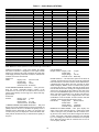
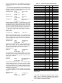
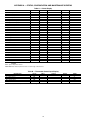
Table 1 — PremierLink Controller Inputs and Outputs
INPUTS
SPACE TEMPERATURE (SPT)
SET POINT ADJUSTMENT (STO)
SUPPLY AIR TEMPERATURE (SAT)
OUTDOOR AIR TEMPERATURE (OAT)
IAQ SENSOR (IAQI)
OUTDOOR AQ/INDOOR HUMIDITY SENSOR (OAQ/IRH)
REMOTE TIME CLOCK/DOOR SWITCH (RMTOCC)
COMPRESSOR LOCKOUT (CMPSAFE)
FIRE SHUTDOWN (FSD)
SUPPLY FAN STATUS (SFS)
FILTER STATUS (FLTS)
ENTHALPY STATUS (ENTH)
OUTPUTS
ECONOMIZER (ECONPOS)
FAN (SF)
COOL STAGE 1 (CMP1)
COOL STAGE 2 (CMP2)
HEAT STAGE 1 (HS1)
HEAT STAGE 2 (HS2)
HEAT 3/EXHAUST/REV VALVE/DEH/OCC RELAY (HS3/EXH/RVS)
POWER
AI (10K Thermistor)
AI (10K Thermistor)
AI (10 K Thermistor)
AI (10K Thermistor)
(4-20 mA)
(4-20 mA)
DI (24 VAC)
DI (24 VAC)
DI (24 VAC)
DI (24 VAC)
DI (24 VAC)
DI (24 VAC)
POWER
4-20 mA
DO Relay (24 VAC, 1A)
DO Relay (24 VAC, 1A)
DO Relay (24 VAC, 1A)
DO Relay (24 VAC, 1A)
DO Relay (24 VAC, 1A)
DO Relay (24 VAC, 1A)
LEGEND
AI — Analog Input
DI — Digital Input
DO — Digital Output
9
TERMINAL(S)
J6-7, J6-6
J6-5, J6-6
J6-3, J6-4
J6-1, J6-2
J5-5, J5-6
J5-2, J5-3
J4-11, J4-12
J4-9, J4-10
J4-7, J4-8
J4-5, J4-6
J4-3, J4-4
J4-1, J4-2
TERMINALS
J9-1, J9-2
J8-18
J8-15
J8-12
J8-9
J8-6
J8-3
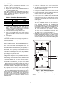
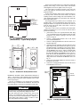
Install the sensor as follows:
1. Locate the 2 Allen type screws at the bottom of the
sensor.
2. Turn the two screws clockwise to release the cover from
the sensor wall mounting plate.
3. Lift the cover from the bottom and then release it from
the top fasteners.
4. Feed the wires from the electrical box through the opening in the center of the sensor mounting plate.
5. Using two no. 6-32 x 1 mounting screws (provided with
the sensor), secure the sensor to the electrical box.
NOTE: Sensor may also be mounted directly on the
wall using 2 plastic anchors and 2 sheet metal screws
(field-supplied).
6. Use 20 gage wire to connect the sensor to the controller.
The wire is suitable for distances of up to 500 ft. Use a
three-conductor shielded cable for the sensor and set
point adjustment connections. The standard CCN
communication cable may be used. If the set point adjustment (slidebar) is not required, then an unshielded, 18 or
20 gage, two-conductor, twisted pair cable may be used.
The CCN network service jack requires a separate,
shielded CCN communication cable. Always use separate cables for CCN communication and sensor wiring. (Refer to Fig. 8-11 for wire terminations.)
7. Replace the cover by inserting the cover at the top of the
mounting plate first, then swing the cover down over the
lower portion. Rotate the 2 Allen head screws counterclockwise until the cover is secured to the mounting plate
and locked in position.
Control Wiring — The PremierLink controller can be
connected to either a Carrier-approved thermostat or CCN
compatible temperature sensor.
1. Turn off power to the control box.
2. Strip the ends of the red, white, and black conductors of
the communication bus cable.
NOTE: When connecting the communication bus cable, a
color code system for the entire network is recommended to
simplify installation and checkout. See Table 2 for the
recommended color code.
Table 2 — Color Code Recommendations
SIGNAL TYPE
+
Ground
–
CCN BUS WIRE
COLOR
Red
White
Black
CCN PLUG PIN
NUMBER
1
2
3
3. Use 4-pin Molex harness with red, white and black wires
to connect the communication wires. Verify the color
codes in Table 2 to ensure the Red (+) wire connects to
Terminal 1. Connect the White (ground) wire to Terminal
2. Connect the Black (–) wire to Terminal 3.
4. Secure all connections in Step 3 with wire nuts.
5. Insert the plug into the existing 4-pin mating connector
on the base module in the main control box (Terminal
J-2).
6. Restore power.
Install Sensors — The PremierLink™ controller can be
used with any combination of CO2 and space temperature sensors. Refer to the instructions supplied with each sensor for
electrical requirements.
NOTE: All sensors are field-installed accessories.
SPACE TEMPERATURE (SPT) SENSOR INSTALLATION — There are four types of SPT sensors available from
Carrier: The 33ZCT55SPT space temperature sensor with
timed override button, the 33ZCT56SPT space temperature
sensor with timed override button and set point adjustment, the
33ZCT59SPT space temperature sensor with LCD screen,
override button, and set point adjustment, and the 33PILOT-01
System Pilot™ communicating room sensor with LCD display
screen, override button, setpoint adjustment, temperature and
setpoint display and system time clock.
The space temperature sensors are used to measure the
building interior temperature. The System Pilot communicating room sensors measure and maintain room temperature by
communicating with the controller. Sensors should be located
on an interior building wall. The sensor wall plate accommodates the NEMA (National Electrical Manufacturers Association) standard 2 x 4 junction box. The sensor can be mounted
directly on the wall surface if acceptable by local codes.
Do not mount the sensor in drafty locations such as near air
conditioning or heating ducts, over heat sources such as baseboard heaters, radiators, or directly above wall-mounted lighting dimmers. Do not mount the sensor near a window which
may be opened, near a wall corner, or a door. Sensors mounted
in these areas will have inaccurate and erratic sensor readings.
The sensor should be mounted approximately 5 ft from the
floor, in an area representing the average temperature in the
space. Allow at least 4 ft between the sensor and any corner
and mount the sensor at least 2 ft from an open doorway. The
SPT sensor wires are to be connected to terminals in the unit
main control board.
1
2
3
4
5
6
RED(+)
WHT(GND)
BLK(-)
CCN COM
SEN
SW1
BRN (GND)
BLU (SPT)
SENSOR WIRING
a33-675ef
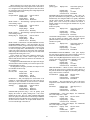
Fig. 8 — Space Temperature Sensor
Typical Wiring (33ZCT55SPT)
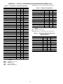
NOTE: See Table 3 for thermistor resistance vs temperature
values.
10
TEMP
(C)
–40
–35
–30
–25
–20
–15
–10
–5
0
5
10
15
20
25
30
35
40
45
50
55
60
65
70
TEMP
(F)
–40
–31
–22
–13
–4
5
14
23
32
41
50
59
68
77
86
95
104
113
122
131
140
149
158
TO
CARRIER
NETWORK
CONNECTION
{
3
4
SEN
SW1
5
6
RED(+)
WHT(GND)
BLK(-)
Fig. 10 — System Pilot Wiring
BRN (COM)
BLK (STO)
BLU (SPT)
Warm
SET
SEN
OPB
COM- PWR+
CCN COM
24 VAC
SENSOR
WIRING
POWER
WIRING
NOTE: Must use a separate isolated transformer.
Fig. 11 — Space Temperature Sensor
Typical Wiring (33ZCT59SPT)
SENSOR WIRING
3. Connect the sensor cable as follows:
a. Connect one wire from the cable to (BLU) wire on
J6-7 analog connector on the controller. Connect
the other end of the wire to the left terminal on the
SEN terminal block of the sensor. See Fig. 11.
b. Connect another wire from the cable to (BRN)
J6-6 analog connector on the controller. Connect
the other end of the wire to the remaining open terminal on the SEN terminal block. On the
33ZCT59SPT sensor, connect this cable to 24-v
COM terminal. A separate 24-vac transformer is
required for this sensor. See Fig. 12.
c. On 33ZCT56SPT and 33ZCT59SPT sensors, connect the remaining wire to the (BLK) STO on J6-5
connector on the controller. Connect the other end
of the wire to the SET terminal on the sensor.
JUMPER
TERMINALS
AS SHOWN
Cool
TO SEPARATE
24-VAC
TRANSFORMER
+ G - + - G
SET
BLK
(T56)
BRN (GND)
BLU (SPT)
(GND)
6 5 4 3 2 1
OR
2
POWER (+)
(-)
RED(+)
RESISTANCE
(Ohms)
335,651
242,195
176,683
130,243
96,974
72,895
55,298
42,315
32,651
25,395
19,903
15,714
12,494
10,000
8,056
6,530
5,325
4,367
3,601
2,985
2,487
2,082
1,752
Wiring Space Temperature Sensor or System Pilot™ Device
— To wire sensor, perform following (see Fig. 8-11):
1. Identify which cable is for the sensor wiring.
2. Strip back the jacket from the cables for at least 3 inches.
Strip 1/4-in. of insulation from each conductor. Cut the
shield and drain wire from the sensor end of the cable.
1
BLACK(-)
WHITE(GND)
{
Table 3 — Thermistor Resistance vs Temperature
Values for Space Temperature Sensor,
Supply Air Temperature Sensor, and
Outdoor Air Temperature Sensor
a33-676ef
Fig. 9 — Space Temperature Sensor
Typical Wiring (33ZCT56SPT)
11
a33-9211
12
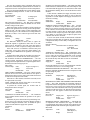
Fig. 12 — PremierLink™ Controller and Sensor Wiring — 33ZCT55SPT and 33ZCT56SPT Space Temperature Sensors;
33ZCSENSAT Supply Air Temperature Sensor; Indoor Relative Humidity Sensor (33ZCSENSRH-01)
33ZCSENCO2 (Outdoor), and 33ZCT55CO2, 33ZCT56CO2 (Indoor) Air Quality Sensors
4-20mA
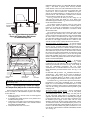
±0.36 F. The SAT sensor is supplied with a gasket and 2 selfdrilling mounting screws.
NOTE: The sensor must be mounted in the discharge of the
unit, downstream of the cooling coil and heat exchanger. Be
sure the probe tip does not come in contact with any of the
unit surfaces. See Fig. 14 and 15 for mounting location.
Do not run sensor or relay wires in the same conduit or raceway with Class 1 AC service wiring. Do not abrade, cut, or
nick the outer jacket of the cable. Do not pull or draw cable
with a force that may harm the physical or electrical properties.
Avoid splices in any control wiring.
Perform the following steps to connect the SAT sensor to
the PremierLink™ controller:
1. Locate the opening in the control box. Pass the sensor
probe through the hole.
2. Drill or punch a 1/2-in. hole in the unit.
3. Use two field-supplied, self-drilling screws to secure the
sensor probe to the unit.
4. Connect the sensor leads to the PremierLink controller’s
wiring harness J6-3,4 board at the terminals labeled SAT
(ORN) and GND (BRN). See Fig. 12.
d. In the control box, install a no. 10 ring type crimp
lug on the shield drain wire. Install this lug under
the mounting screw of the PremierLink controller.
e. On 33ZCT56SPT sensors, install a jumper
between the two center terminals (right SEN and
left SET). See Fig. 9.
f. Refer to Fig 10 for the System Pilot™ device wiring. Once the System Pilot device is powered up,
it will display the time of day and space temperature. Refer to the System Pilot Installation and
Operation manual for programming to attach the
sensor to the PremierLink control.
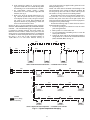
NOTE: See Fig. 13 for space temperature sensor averaging.
SUPPLY AIR TEMPERATURE (SAT) SENSOR INSTALLATION — The 33ZCSENSAT supply air temperature sensor
is required for controller operation. The sensor consists of a
thermistor encased within a stainless steel probe. The SAT
sensor probe is 6-in. nominal length with 114 in. of unshielded,
2-conductor 18 AWG twisted-pair cables. The sensor temperature range is –40 to 245 F with a nominal resistance of
10,000 ohms at 77 F. The sensor measures accuracy of
J6
6
7
RED
RED
BLK
BLK
RED
RED
RED
BLK
BLK
BLK
a33-678ef
SENSOR 1
SENSOR 2
SENSOR 3
SENSOR 4
SPACE TEMPERATURE AVERAGING — 4 SENSOR APPLICATION
J6
RED
RED
BLK
BLK
BLK
BLK
SENSOR 1
SENSOR 3
SENSOR 2
RED
BLK
7
RED
RED
6
RED
RED
BLK
BLK
SENSOR 4
SENSOR 6
SENSOR 5
LEGEND
Factory Wiring
RED
RED
BLK
BLK
Field Wiring
a33-679ef
SENSOR 8
SENSOR 7
SPACE TEMPERATURE AVERAGING — 9 SENSOR APPLICATION
Fig. 13 — Space Temperature Averaging
13
SENSOR 9
INDOOR AIR QUALITY CO2 SENSOR INSTALLATION
(IAQ) — The indoor air quality sensor accessory monitors
carbon dioxide (CO2) levels. This information is used to monitor IAQ levels. Three types of sensors are provided. The wall
sensor can be used to monitor the conditioned air space.
Sensors use infrared technology to measure the levels of CO2
present in the air. The wall sensor is available with or without
an LCD readout to display the CO2 level in ppm.
The CO2 sensors are all factory set for a range of 0 to
2000 ppm and a linear mA output of 4 to 20. Refer to the
instructions supplied with the CO2 sensor for electrical requirements and terminal locations.
To accurately monitor the quality of the air in the conditioned air space, locate the sensor near a return-air grille (if
present) so it senses the concentration of CO2 leaving the
space. The sensor should be mounted in a location to avoid
direct breath contact.
Do not mount the IAQ sensor in drafty areas such as near
supply ducts, open windows, fans, or over heat sources. Allow
at least 3 ft between the sensor and any corner. Avoid mounting
the sensor where it is influenced by the supply air; the sensor
gives inaccurate readings if the supply air is blown directly onto
the sensor or if the supply air does not have a chance to mix
with the room air before it is drawn into the return airstream.
Wiring the Indoor Air Quality Sensor — To wire the sensors
after they are mounted in the conditioned air space or outdoor
location, see Fig. 12 and the instructions shipped with the sensors. For each sensor, use two 2-conductor 18 AWG (American
Wire Gage) twisted-pair cables (unshielded) to connect the separate isolated 24 vac power source to the sensor and to connect
the sensor to the control board terminals. To connect the sensor
to the control, identify the positive (4 to 20 mA) and ground
(SIG COM) terminals on the sensor. Connect the 4-20 mA terminal to terminal IAQ (RED) and connect the SIG COM terminal to terminal GND (BRN).
Combination Temperature and CO2 Sensor — If using the
older style combination temperature and CO2 sensor
(33ZCT55CO2 or 33ZCT56CO2), refer to the installation instructions provided with the sensor. See Fig. 16 for wiring. If
using the combination temperature and CO2 sensor
33ZCPTCO2-01 or 33ZCSPTCO2LCD-01, refer to he installation instructions provided with the sensor. See Fig. 17 for
wiring.
OUTDOOR AIR QUALITY CO2 SENSOR INSTALLATION (OAQ) — The outdoor air CO2 sensor is designed to
monitor carbon dioxide (CO2) levels in the air and interface
with the ventilation damper in an HVAC system. The OAQ
sensor is packaged with an outdoor cover. See Fig. 18 and 19.
The outdoor air CO2 sensor must be placed in an area that is
representative of the entire conditioned space. A mounting
height of 6 ft is recommended. For installation where it is not
necessary to reach the control, it may be mounted higher on the
wall or on the ceiling, provided the location represents a good
sampling of air.
Wiring the Outdoor Air CO2 Sensor — Power requirements
are 18 to 36 VAC RMS 50/60 Hz; 18 to 42 vdc polarity
protected/dependent; and 70 mA average, 100 mA peak at
24 vdc. All system wiring must be in compliance with all
applicable local and national codes. A dedicated power supply
is required for this sensor. A two-wire cable is required to wire
the dedicated power supply for the sensor. The two wires
should be connected to the power supply and terminals 1 and 2.
To connect the sensor to the control, identify the positive (4 to
20 mA) and ground (SIG COM) terminals on the sensor. Connect the 4 to 20 mA terminal OAQ (BLU) terminal J5-2. Connect the SIG COM terminal to terminal GND (BRN) terminal
J5-3. See Fig. 16.
a33-684ef
SUPPLY AIR
TEMPERATURE
SENSOR
ROOF
CURB
SUPPLY AIR
RETURN AIR
Fig. 14 — Typical Mounting Location for
Supply Air Temperature (SAT) Sensor
On Small Rooftop Units
DIRECT DRIVE
a33-685ef
MOTOR
DIMPLED HEAT
EXCHANGER
SAT
LOCATION
IMPORTANT: Be certain SAT does not come in contact with
heat exchanger tubes.
Fig. 15 — Typical Mounting Location for Supply
Air Temperature (SAT) Sensor in Heat Exchanger
Perform the following steps if state or local code requires
the use of conduit, or if the installation requires a cable length
of more than 8 ft:
1. Secure the probe to the unit with two field-supplied
self-drilling screws.
2. If extending cable length beyond 8 ft, use plenum rated,
20 AWG, twisted pair wire.
3. Connect the sensor leads to the PremierLink controller’s
wiring harness terminal board at the terminals labeled
SAT (ORN) and GND (BRN).
4. Neatly bundle and secure excess wire.
14
15
2
J4
3
1
2
J5
3
SEE NOTE 1
+
1
-
2
J3
SEE NOTE 2
24 VAC
DEDICATED 24 VAC
TRANSFORMER
Fig. 16 — PremierLink™ Controller Wiring — Combination Temperature and CO2 Sensor — 33ZCT55CO2, 33ZCT56CO2
NOTES:
1. Optional 24 VDC power source may ONLY be used if PremierLink control is using a dedicated transformer.
2. Do not use 24 VAC power source if using 24 VDC from PremierLink controller.
1
J5 2
3
1
BLU
BRN
AC+ / DC+
AC- / DC-
16
THERM +
THERM -
4 - 20 mA
COM
0-5 / 10 VDC
Fig. 17 — PremierLink™ Controller Wiring — Combination Temperature and CO2 Sensor — 33ZCSPTCO2-01, 33ZCSPTCO2LCD-01
NOTES:
1. Remove RED wire from J4-1, J4-3, J4-5, J4-7, J4-9, or J4-11 (whichever is not being used) and insert J5-4.
2. Sensor does NOT have an override button.
18-42 VDC
18-30 VAC
BRN
BLU
RED
a33-4359
If the sensor is installed directly on a wall surface, install the
humidity sensor using 2 screws and 2 hollow wall anchors
(field-supplied). Do not over tighten screws. See Fig. 20.
The sensor must be mounted vertically on the wall. The
Carrier logo should be oriented correctly when the sensor is
properly mounted.
Avoid corner locations. Allow at least 4 ft between the sensor and any corner. Airflow near corners tends to be reduced,
resulting in erratic sensor readings. The sensor should be vertically mounted approximately 5 ft up from the floor, beside the
space temperature sensor.
For wiring distances up to 500 feet, use a 3-conductor, 18 or
20 AWG cable. A CCN communication cable can be used, although the shield is not required. The shield must be removed
from the sensor end of the cable if this cable is used. See
Fig. 21 for wiring details.
The power for the sensor is provided by the PremierLink
controls on terminal J5-4 (+33 to +35vdc). To wire the sensor
perform the following:
1. At the sensor, remove 4-in. of jacket from the cable. Strip
1/ -in. of insulation from each conductor. Route the cable
4
through the wire clearance opening in the center of the
sensor. See Fig. 20.
2. Connect a field-supplied BLACK wire to the sensor
screw terminal marked Vin.
3. Connect a field-supplied RED wire into the sensor screw
terminal marked Io.
4. At the PremierLink controller, route the cable away from
high voltage wiring and disconnect the power to prevent
accidental shorting or grounding of wires when connecting the sensor. Remove the J5 Molex female plug and locate the BROWN wire on pin 3. Using a small, flat blade
screwdriver gently press down in the slot on the side of
the plug while pulling on the BROWN wire to remove it
from slot. Re-insert the BROWN wire in the pin 4 slot
making sure it is securely seated. There should now be an
empty slot between the BLUE and BROWN wires. See
Fig. 21.
5. Connect the field-supplied RED wire from the sensor to
the BLUE wire on J5-2.
6. Connect the field-supplied BLACK wire from the sensor
to the BROWN wire on J5-4.
+ 0-10VDC
- SIG COM (J5-3)
+ 4-20mA (J5-2)
ALARM
NC
COM RELAY
NO CONTACTS
}
8765432 1
a33-686ef
Fig. 18 — Outdoor Air Quality (CO2) Sensor
(33ZCSENCO2) — Typical Wiring Diagram
SIDE VIEW
Fig. 19 — Outdoor Air Quality Sensor Cover
MOUNTING
HOLES
Gnd
WIRING
OPENING
Vo
5
CAUTION
Vin
4
Io
HUMIDITY SENSOR (WALL-MOUNTED) INSTALLATION — The accessory space humidity sensor is installed on
an interior wall to measure the relative humidity of the air within the occupied space.
The use of a standard 2 x 4-in. electrical box to accommodate the wiring is recommended for installation. The sensor can
be mounted directly on the wall, if acceptable by local codes.
3
COVER REMOVED
SW2
2
2 1
1
H G 24 VAC
OR
+ - 24 VDC
6
ON
Do NOT clean or touch the sensing element with chemical
solvents as they can permanently damage the sensor.
DO NOT mount the sensor in drafty areas such as near
heating or air-conditioning ducts, open windows, fans, or
over heat sources such as baseboard heaters, radiators, or
wall-mounted light dimmers. Sensors mounted in those
areas will produce inaccurate readings.
a33-9141
Fig. 20 — Humidity Sensor Installation
17
NOTE: Remove BROWN wire from J5-3 and insert into J5-4.
18
Fig. 21 — Humidity Sensor Wiring
4-20mA
a33-9212
OUTDOOR AIR TEMPERATURE SENSOR (Fig. 22-25) —
The OAT sensor must be located properly. For outdoor locations use sensor 33ZCSENOAT. For duct mounting in the
fresh air intake, use sensor 33ZCSENPAT. The sensor must be
installed immediately upstream from outdoor-air damper
where it will accurately sense the temperature of the outdoor
air entering the mixing box. See Fig. 22 and 23. For applications without economizer, the sensor may be located in the outdoor air duct near the outdoor-air intake (Fig. 23) or on the
exterior of the building (Fig. 22). The thermistor has a range of
–40 to 245 F and a resistance of 10,000 ohms at 77 F.
Do not mount the sensor in direct sunlight. Inaccurate readings may result. Do not mount the sensor near the exhaust from
air-handling units or compressors, near leakage drafts of indoor
air, or near shrubbery or trees, or under direct water runoff.
If the sensor is installed outdoors, perform the following instructions. Install the 1/2-in. conduit connector into the rear
opening. Tighten the conduit connector securely to prevent
water leakage into the assembly. Mount the assembly onto the
1/ -in. conduit and secure by tightening the conduit nut. After
2
the sensor wiring is completed, secure the gasket and cover in
place using the screws provided with the cover. See Fig. 24.
If the sensor is to be mounted in the outdoor air duct, use the
33ZCSENPAT sensor which has a 2 x 4-in. by 11/2-in. deep
electrical box. Remove the cover and enter the knockout from
the rear of the box. Install the sensor through the opening so
that the sensor leads are inside the electrical box. Secure the
sensor to the electrical box using a field-supplied 1/2-in. conduit nut. Drill a 1/2-in. hole in the outdoor-air duct about a foot
upstream of the outdoor-air damper. Apply a 1/4-in. bead of silicone type sealer around the opening and install the sensor
through the hole. Secure the electrical box to the duct using 2
field-supplied, no. 10 sheet metal screws. See Fig. 25.
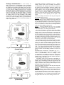
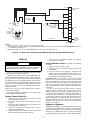
FACTORY-INSTALLED CONTROLLER — The PremierLink™ controller is available as a factory-installed option on
some units. Additional terminal boards are provided for wiring.
Sensors and input devices are wired to terminal boards instead
of directly to the Premierlink controller. See Fig. 26 and 27.
RETURN
AIR
a33-688ef
OAT
OUTDOOR
AIR
ROOF TOP
UNIT
Fig. 23 — OAT Sensor Location
in Outside Air Duct (P/N 33ZCSENPAT)
Connect to CCN Communication Bus — The
PremierLink™ controller connects to the bus in a daisy chain
arrangement. Negative pins on each component must be
connected to respective negative pins, and likewise, positive
pins on each component must be connected to respective positive pins. The controller signal pins must be wired to the signal
ground pins. Wiring connections for CCN must be made at the
3-pin plug.
At any baud (9600, 19200, 38400 baud), the number of controllers is limited to 239 devices maximum. Bus length may not
exceed 4000 ft, with no more than 60 total devices on any
1000-ft section. Optically isolated RS-485 repeaters are
required every 1000 ft.
NOTE: Carrier device default is 9600 band.
COMMUNICATION BUS WIRE SPECIFICATIONS —
The CCN Communication Bus wiring is field-supplied and
field-installed. It consists of shielded 3-conductor cable with
drain (ground) wire. The cable selected must be identical to the
CCN Communication Bus wire used for the entire network.
See Table 4 for recommended cable.
Table 4 — Recommended Cables
MANUFACTURER
Alpha
American
Belden
Columbia
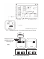
Connect Discrete Inputs — If used, wire the dry contact switches, compressor safety switch, and supply fan status
switch to the PremierLink controller. See Fig. 28 for wiring.
CABLE PART NO.
2413 or 5463
A22503
8772
02525
NOTE: Conductors and drain wire must be at least 20 AWG,
stranded, and tinned copper. Individual conductors must be
insulated with PVC, PVC/nylon, vinyl, Teflon, or polyethylene. An aluminum/polyester 100% foil shield and an outer
jacket of PVC, PVC/nylon, chrome vinyl, or Teflon with a
minimum operating temperature range of –20 C to 60 C is
required. Do not run communication wire in the same conduit
as or next to any AC voltage wiring.
The communication bus shields must be tied together at
each system element. If the communication bus is entirely
within one building, the resulting continuous shield must be
connected to ground at only one single point. If the communication bus cable exits from one building and enters another
building, the shields must be connected to the grounds at a
lightning suppressor in each building (one point only).
Fig. 22 — Outdoor Air Temperature Sensor
Installation — Located on Building Wall
(P/N 33ZCSENOAT)
19
2.8125 IN.
(71.4 mm)
0.5000 IN.
(12.7 mm) NPT
THREADED
CONDUIT
OPENINGS TYP.
GROUND
SCREW
4.5625 IN.
(115.9 mm)
2.0000 IN.
(50.8 mm)
SINGLE-GANG
ALUMINUM
BELL BOX
FOAM COVER
GASKET
ALUMINUM
COVER
4.9200 IN.
(125.0 mm)
Fig. 24 — Outdoor Air Temperature Sensor (P/N 33ZCSENOAT)
33ZCSENPAT SENSOR
DUCT MOUNTED
LEGEND
OA — Outdoor Air
OAT — Outdoor Air Temperature
Fig. 25 — Outdoor Air Temperature Sensor Installation (P/N 33ZCSENPAT)
20
a33-899
Fig. 26 — PremierLink™ Factory-Installed Controller Wiring for R-22 Units (48/50TM,TF,HJ,HE003-014
and 50TFQ,HJQ,HEQ003-012)
a33-9213
ROOFTOP UNIT’S
CENTRAL TERMINAL BOARD
(HK50AA049)
CONTROL
BOARD
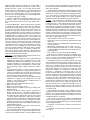
Fig. 27 — PremierLink™ Factory-Installed Controller Wiring for R-410A Units
(48/50TC,HC004-028 and 50TCQ,HCQ004-028)
21
22
4-20mA
Fig. 28 — PremierLink™ Field-Installed Controller Discrete Input Wiring
NOTE: Remove red wire from J4-9 to prevent 24 VAC shorting out other components or ground.
a33-9214
OUTDOOR ENTHALPY CONTROL (Fig. 30) — Outdoor
enthalpy control requires only an enthalpy switch/receiver
(33CSENTHSW). The enthalpy switch/receiver is mounted in
the outdoor air inlet and calculates outdoor air enthalpy. The
enthalpy switch/receiver energizes the relay output when the
outdoor enthalpy is above 28 BTU/lb OR dry bulb temperature is above 75 F and is deenergized when the outdoor
enthalpy is below 27 BTU/lb AND dry bulb temperature is
below 74.5 F. The relay output is wired to the unit economizer
which will open or close depending on the output of the
switch.
NOTE: The enthalpy calculation is done using an average altitude of 1000 ft above sea level.
Mounting — Mount the enthalpy switch/receiver in a location
where the outdoor air can be sampled (such as the outdoor air
intake). The enthalpy switch/receiver is not a NEMA 4 enclosure and should be mounted in a location that is not exposed to
outdoor elements such as rain or snow. Use two field-supplied
no. 8 x 3/4-in. TEK screws. Insert the screws through the holes
in the sides of the enthalpy switch/receiver.
Wiring — Carrier recommends the use of 18 to 22 AWG
twisted pair or shielded cable for all wiring. All connections
must be made with 1/4-in. female spade connectors.
A 24-vac transformer is required to power the enthalpy
switch/receiver; as shown in Fig. 30, the PremierLink™ board
provides 24 vac. Connect the GND and 24-vac terminals on the
enthalpy switch/receiver to the terminals on the transformer.
On some applications, the power from the economizer harness
can be used to power the enthalpy switch/receiver. To power
the enthalpy switch/receiver from the economizer harness, connect power of the enthalpy switch/receiver to the red and
brown wires (1 and 4) on the economizer harness.
For connection to rooftop units with PremierLink™ control,
connect the LOW Enthalpy terminal on the enthalpy switch/receiver to J4 — pin 2 of the PremierLink control on the HVAC
(Heating, Ventilation, and Air Conditioning) unit. The switch
can be powered through the PremierLink control board if desired. Wire the 24-vac terminal on the enthalpy switch/receiver
to J4 — pin 1 on the PremierLink control. Wire the GND terminal on the enthalpy switch/receiver to J1 — pin 2 on the PremierLink control. The HI Enthalpy terminal is not used. See
Fig. 31.
DIFFERENTIAL ENTHALPY CONTROL (Fig. 32) —
Differential enthalpy control requires both an enthalpy switch/
receiver (33CSENTHSW) and an enthalpy sensor
(33CSENTSEN). The enthalpy switch/receiver is mounted in
the outdoor air inlet and calculates outdoor air enthalpy. The
enthalpy sensor is mounted in the return airstream and calculates the enthalpy of the indoor air.
The enthalpy switch/receiver energizes the HI Enthalpy relay output when the outdoor enthalpy is greater than the indoor
enthalpy. The LOW Enthalpy terminal is energized when the
outdoor enthalpy is lower than the indoor enthalpy. The relay
output is wired to the unit economizer which will open or close
depending on the output of the switch.
NOTE: The enthalpy calculation is done using an average altitude of 1000 ft above sea level.
Mounting — Mount the enthalpy switch/receiver in a location
where the outdoor air can be sampled (such as the outdoor air
intake). The enthalpy switch/receiver is not a NEMA 4 enclosure and should be mounted in a location that is not exposed to
outdoor elements such as rain, snow, or direct sunlight. Use
two field-supplied no. 8 x 3/4-in. TEK screws. Insert the screws
through the holes in the sides of the enthalpy switch/receiver.
Enthalpy Switch/Receiver — The accessory en-
thalpy switch/receiver (33CSENTHSW) senses temperature
and humidity of the air surrounding the device and calculates
the enthalpy when used without an enthalpy sensor. The relay is
energized when enthalpy is high and deenergized when enthalpy is low (based on ASHRAE [American Society of Heating,
Refrigerating, and Air Conditioning Engineers] 90.1 criteria). If
an accessory enthalpy sensor (33CSENTSEN) is attached to the
return air sensor input, then differential enthalpy is calculated.
The relay is energized when the enthalpy detected by the return
air enthalpy sensor is less than the enthalpy at the enthalpy
switch/receiver. The relay is deenergized when the enthalpy detected by the return air enthalpy sensor is greater than the enthalpy at the enthalpy switch/receiver (differential enthalpy control). See Fig. 29 and 30.
a33-833tf
Fig. 29 — Enthalpy Switch/Receiver Dimensions
(33CSENTHSW)
a33-834tf
Fig. 30 — Enthalpy Sensor Dimensions
(33CSENTSEN)
23
a33-9215
4-20mA
*Used with Differential Enthalpy Control only.
Fig. 31 — Typical Wiring Schematic — Carrier Rooftop Unit with PremierLink™ Controls
a33-839tf
120 VAC
LINE VOLTAGE
24 VAC
SECONDARY
24 VAC OUTPUT FROM N/C CONTACT WHEN THE
OUTDOOR ENTHALPY IS LESS THAN THE
ORN
INDOOR ENTHALPY
(ENABLE ECONOMIZER)
24 VAC OUTPUT FROM N/O CONTACT WHEN THE
INDOOR ENTHALPY IS GREATER THAN THE
OUTDOOR ENTHALPY
(ENABLE ENERGYSRECYCLER)
4-20 24-36
mA VDC
IN OUT
HI LOW GND 24
ENTHALPY
VAC
24-36 4-20
VDC mA
IN OUT
LEGEND
N/C — Normally Closed
N/O — Normally Open
33CSENTHSW
33CSENTSEN
JUMPER SETTINGS FOR 33CSENTHSW
JUMPER SETTINGS FOR 33CSENTSEN
0%
50%
OFF
100%
M1
24
M2
M3
0%
50%
OFF
100%
M1
M2
M3
Fig. 32 — Differential Enthalpy Control Wiring
Mount the enthalpy sensor in a location where the indoor air
can be sampled (such as the return air duct). The enthalpy
sensor is not a NEMA 4 enclosure and should be mounted in a
location that is not exposed to outdoor elements such as rain or
snow. Use two field-supplied no. 8 x 3/4-in. TEK screws. Insert
the screws through the holes in the sides of the enthalpy sensor.
Wiring — Carrier recommends the use of 18 to 22 AWG
twisted pair or shielded cable for all wiring. All connections
must be made with 1/4-in. female spade connectors.
The PremierLink™ board provides 24-vac to power the enthalpy switch/receiver. Connect the GND and 24-vac terminals
on the enthalpy switch/receiver to the terminals on the transformer. On some applications, the power from the economizer
harness can be used to power the enthalpy switch/receiver. To
power the enthalpy switch/receiver from the economizer harness, connect power of the enthalpy switch/receiver to the red
and brown wires (1 and 4) on the economizer harness.
Connect the LOW Enthalpy terminal on the enthalpy
switch/receiver to J4 — pin 2 of the PremierLink control on the
HVAC unit. The switch can be powered through the PremierLink control board if desired. Wire the 24 vac terminal on the
enthalpy switch/receiver to J4 — pin 1 on the PremierLink
control. Wire the GND terminal on the enthalpy switch/
receiver to J1 — pin 2 on the PremierLink control. The HI
Enthalpy terminal is not used. See Fig. 31.
Connect the 4-20 mA In terminal on the enthalpy switch/
receiver to the 4-20 mA Out terminal on the return air enthalpy
sensor. Connect the 24-36 VDC Out terminal on the enthalpy
switch/receiver to the 24-36 VDC In terminal on the return air
enthalpy sensor. See Fig. 32.
Enthalpy Switch/Receiver Jumper Settings — There are two
jumpers. One jumper determines the mode of the enthalpy
switch/receiver. The other jumper is not used. To access the
jumpers, remove the 4 screws holding the cover on the enthalpy switch/receiver and then remove the cover. The factory settings for the jumpers are M1 and OFF.
The mode jumper should be set to M2 for differential enthalpy control. The factory test jumper should remain on OFF
or the enthalpy switch/receiver will not calculate enthalpy.
Enthalpy Sensor Jumper Settings — There are two jumpers.
One jumper determines the mode of the enthalpy sensor. The
other jumper is not used. To access the jumpers, remove the
4 screws holding the cover on the enthalpy sensor and then
remove the cover. The factory settings for the jumpers are M3
and OFF.
The mode jumper should be set to M3 for 4 to 20 mA
output. The factory test jumper should remain on OFF or the
enthalpy sensor will not calculate enthalpy.
BRACKET
HH57AC077
ENTHALPY
CONTROL AND
OUTDOOR AIR
ENTHALPY
SENSOR
a39-1901ef
HH57AC078 RETURN AIR
ENTHALPY SENSOR
(USED WITH ENTHALPY
CONTROL FOR DIFFERENTIAL
ENTHALPY OPERATION)
C7400
A
1004
+
MOUNTING PLATE
a39-1905ef
Fig. 33 — Enthalpy Control, Sensor,
and Mounting Plate
a33-690ef
OUTSIDE
AIR
ENTHALPY
SWITCH
RETURN AIR
ENTHALPY SENSOR
DIFFERENTIAL
ENTHALPY
CONTROLLER
Fig. 34 — Location of Differential Enthalpy
Controller and Return Air Enthalpy Sensor
on 50TJ Rooftop Unit
OUTDOOR AIR ENTHALPY SENSOR/ENTHALPY
CONTROLLER (HH57AC077) — To wire the outdoor air
enthalpy sensor, perform the following (see Fig. 35 and 36):
NOTE: The outdoor air sensor can be removed from the back
of the enthalpy controller and mounted remotely.
1. Use a 4-conductor, 18 or 20 AWG cable to connect the
enthalpy control to the PremierLink controller and power
transformer.
2. Connnect the following 4 wires from the wire harness
located in rooftop unit to the enthalpy controller:
a. Connect the BRN wire to the 24 vac terminal
(TR1) on enthalpy control and to pin 1 on 12-pin
harness.
b. Connect the RED wire to the 24 vac GND terminal
(TR) on enthalpy sensor and to pin 4 on 12-pin
harness.
c. Connect the ORN/GRAY wire to J4-2 on PremierLink controller and to terminal (3) on enthalpy sensor.
d. Connect the RED/GRAY wire to J4-1 on PremierLink controller and to terminal (2) on enthalpy sensor.
Enthalpy Sensors and Control — The enthalpy
control (HH57AC077) is supplied as a field-installed accessory
to be used with the economizer damper control option. The
outdoor air enthalpy sensor is part of the enthalpy control. The
separate field-installed accessory return air enthalpy sensor
(HH58AC078) is required for differential enthalpy control. See
Fig. 33.
NOTE: The enthalpy control must be set to the “D” setting
for differential enthalpy control to work properly.
The enthalpy control receives the indoor and return
enthalpy from the outdoor and return air enthalpy sensors
and provides a dry contact switch input to the PremierLink
controller. Locate the controller in place of an existing
economizer controller or near the actuator. The mounting plate
may not be needed if existing bracket is used. See Fig. 34.
A closed contact indicates that outside air is preferred to the
return air. An open contact indicates that the economizer
should remain at minimum position.
25
to 20 mA output on the controller to be permanently damaged.
This condition is followed by a constant 36 VDC output from
the PremierLink economizer output (J-9).
NOTE: If installing in a Carrier rooftop, use the two gray
wires provided from the control section to the economizer
to connect PremierLink™ controller to terminals 2 and 3 on
enthalpy sensor. If NOT using Carrier equipment, wires
may need to be field supplied and installed.
RETURN AIR ENTHALPY SENSOR — Mount the returnair enthalpy sensor (HH57AC078) in the return-air duct. The
return air sesnor is wired to the enthalpy controller
(HH57AC077). See Fig. 35. The outdoor enthalpy changeover
set point is set at the controller.
To wire the return air enthalpy sensor, perform the following (see Fig. 35):
1. Use a 2-conductor, 18 or 20 AWG, twisted pair cable to
connect the return air enthalpy sensor to the enthalpy
controller.
2. At the enthalpy control remove the factory-installed resistor from the (SR) and (+) terminals.
3. Connect the field-supplied RED wire to (+) spade
connector on the return air enthalpy sensor and the (SR+)
terminal on the enthalpy controller. Connect the BLK
wire to (S) spade connector on the return air enthalpy
sensor and the (SR) terminal on the enthalpy controller.
ENTHALPY CONTROLLER
A
B
TR
C
D SO
TR1
SR
+
2
+
To avoid permanent damage to the PremierLink 4 to
20 mA connection, a signal loop isolator must be installed
when using the Q769B adapter.
The Q769B adapter is supplied with female quick-connect
terminal that fits over the male quick-connect P1 and P on the
actuator.
To connect the Q769B adapter to the actuator, follow these
steps and refer to Fig. 37:
1. Remove power from unit.
2. Mount the adapter on the actuator by gently pushing the
adapter onto the P1 and P terminals on actuator.
NOTE: Be sure the plus (+) terminal on the adapter connects to P1 on the actuator and the minus (–) terminal on
the adapter connects to P terminal on the actuator. See
Fig. 37.
3. Using field-supplied wire, connect the plus (+) terminal
on the adapter to the plus (+) terminal on the loop isolator.
Connect the minus (–) terminal on the adapter to the
minus (–) terminal on the loop isolator.
4. Connect 24 vac to actuator terminals TR and TR1.
5. Connect the plus (+) terminal from the loop isolator to
J9-1 terminal on the PremierLink controller. Connect the
minus (–) terminal from the loop isolator to J9-2 terminal
on the PremierLink controller.
6. Restore power to unit.
Q769C ADAPTER — The Q769C adapter incorporates a female quick-connect terminal that attaches to P1 and P male
quick-connects on the actuator.
S (OUTDOOR
AIR
+ ENTHALPY
SENSOR)
RED
BRN
BLK
RED
S (RETURN AIR
+ ENTHALPY
SENSOR)
3
1
CAUTION
GRAY
LED
GRAY
WIRE HARNESS
IN UNIT
a33-928ef
NOTES:
1. Remove factory-installed jumper across SR and + before connecting wires from return air sensor.
2. Switches shown in high outdoor air enthalpy state. Terminals 2
and 3 close on low outdoor air enthalpy relative to indoor air
enthalpy.
3. Remove sensor mounted on back of control and locate in outside airstream.
IMPORTANT: It is recommended that the Q769C adapter
be used with a field-supplied 500-ohm resistor across the
terminals.
Using the Q769C and actuator requires a separate, fieldsupplied transformer because the actuator with a Q769C is
a positive ground device. The PremierLink controller is a
negative ground device.
The positive P1 terminal on the Q769C goes to ground.
See Fig. 38.
Fig. 35 — Outside and Return Air
Enthalpy Sensor Wiring
See Fig. 36 for enthalpy controller to PremierLink controller wiring.
Economizer — The PremierLink controller will interface
To connect the Q769C adapter to the actuator, follow the steps
below and refer to Fig. 38:
1. Remove power from unit.
2. Mount the adapter onto the actuator by gently pushing the
adapter onto terminals P1 and P of actuator.
3. NOTE: Be sure the plus (+) terminal on the adapter
connects to P1 on the actuator and the minus (–) terminal
on the adapter connects to P terminal on the actuator.
See Fig. 38.
4. Connect 24 vac to actuator terminals TR and TR1.
5. Connect 500-ohm resistor (field supplied) to the plus (+)
and minus (–) terminals on adapter.
6. Connect the plus (+) terminal from the adapter to J9-1
terminal on the PremierLink controller. Connect the
minus (–) terminal from the adapter to J9-2 terminal on
the PremierLink controller.
7. Restore power to unit.
with an economizer in some applications. Most common economizers will contain a Honeywell actuator (Honeywell part
number M7415).
An adapter (Honeywell part number Q769B or Q769C)
must be used to enable the 4 to 20 mA signal from the PremierLink controller to control the position of the economizer. Refer
to Honeywell Q769B and Q769C accessory installation
instructions for wiring details.
CAUTION
Disconnect power supply before making wiring connections to prevent electrical shock and equipment damage.
Q769B ADAPTER — Because the Honeywell adapter is designed for a negative 4 to 20 mA input instead of a positive signal, the Q769B adapter requires a separate transformer and a
current loop isolator to perform properly. Connecting the
adapter directly to the PremierLink controller could cause the 4
26
27
4-20mA
Fig. 36 — PremierLink Controller Wiring — Enthalpy Control (HH57AC077)
NOTE: If PremierLink™ controller is grounded and actuator is grounded on common side, then common wire from PremierLink controller J9-2 is
not needed.
a33-9216
installed in the DA mode so damper will close automatically
on power shut down.
If Reverse Acting (RA) operation is desired, move Switch 3
to the RA position. An increasing control signal drives the
actuator toward the spring return position in RA mode.
SWITCH SELECTION — The type of input control signal is
determined by the position of Switch 5. With Switch 5 in the
VDC position (factory setting), the signal is DC voltage. With
Switch 5 min the mA position, the input signal changes to
current input. See Fig. 39 and Table 6. The switch should be set
to mA for use with PremierLink controller.
NOTE: To change the factory setting, use a 1/8-in. (3-mm)
flat-blade screwdriver to position the mode switch to the alternate setting.
24 VAC
TR
24 VAC
TR1
TRANSFORMER
T
SENSOR
T1
PREMIERLINK
CONTROL
J9
Q769B
ADAPTER
MIN.
POS
P1
P
+
-
+
2
-
1
LOOP
ISOLATOR
M7415
ACTUATOR
+
-
-
+
Table 5 — Actuator Drive Direction Settings
POSITION OF
SWITCH 3 AND THE DRIVE DIRECTION DRIVE DIRECTION
DIRECTION OF
WITH A MINIMUM WITH A MAXIMUM
SPRING RETURN
INPUT SIGNAL
INPUT SIGNAL
DRIVE
DA/CCW
CCW
CW
RA/CCW
CW
CCW
DA/CW
CW
CCW
RA/CW
CCW
CW
Fig. 37 — PremierLink™ Control Wiring to
Q769B Adapter and Actuator
a33-900ef
24 VAC
TR
CCW
CW
DA
RA
24 VAC
TR1
TRANSFORMER
(SEPARATE,
FIELD-SUPPLIED)
T
T1
PREMIERLINK
CONTROL
J9
Q769C
ADAPTER
P1
P
LEGEND
Counterclockwise
Clockwise
Direct Action
Reverse Action
Table 6 — Mode Selection Information
SENSOR
MIN.
POS
—
—
—
—
+
-
-
+
500 OHM
RESISTOR
2
MODE
SWITCHES
5
4
1
3
2
1
M7415
ACTUATOR
SWITCH FUNCTIONS
VDC or mA
0 to 10 VDC (0 to 20 mA or
2 to 10 VDC (4 to 20 mA)
Direct Acting (DA) or
Reverse Acting (RA)
FIXED or AUTO
— or 6 to 9 VDC
FACTORY
SETTINGS
VDC
0 to 10
DA
FIXED
—
NOTE: The 6 to 9 VDC setting of Switch 1 overrides Switch 4.
WIRING (See Fig. 40-41B) — The wires for power and
signal transmission from PremierLink controller to economizer
are provided in the 12-pin harness that is standard on all Carrier
equipment. To connect the economizer actuator (installed on
Belimo or Johnson Controls actuators) to PremierLink controller, connect the pink wire on actuator to purple wire on PremierLink J9-1. See Fig. 41A and 41B.
NOTE: To retrofit PremierLink controller to older 4 to 20 mA
actuator, connect the red wire on the actuator wire harness to
the purple wire on the PremierLink J9-1. Connect the yellow
and white wires from the actuator wire harness to the 24-volt
AC transformer on equipment. See Fig. 40.
Fig. 38 — PremierLink Control Wiring to
Q769C Adapter and Actuator
Economizer with 4 to 20 mA Actuator — The
PremierLink controller can be connected to an economizer.
The economizer features a Johnson 4 to 20 mA actuator.
IMPORTANT: The actuator that comes with the economizer is a stepper-type actuator and is NOT compatible
with PremierLink control. This actuator should be replaced
with a 4 to 20 mA actuator.
DRIVE DIRECTION — The actuator drive direction is
dependent upon the position of Switch 3 and the spring return
direction. See Table 5. The actuator is factory set for Direct
Acting (DA) operation with Switch 3 in the DA position. An
increasing control signal drives the actuator away from the
spring return position in DA mode. The actuator should be
IMPORTANT: Make sure the common side is grounded
for both the PremierLink power and the actuator power.
This is especially important if separate transformers are
used.
28
MOVE TO LEFT
FOR 4-20mA CONTROL
WITH PREMIERLINK
CONTROLLER
5 4 3 2 1
VDC
0-10
DA
FIXED
—
mA
2-10
RA
AUTO
6-9
Fig. 39 — Position of Actuator Mode Switches
(Factory Default)
WIRE HARNESS
FROM ACTUATOR
Gray
White/Red
Red
Yellow
White
a33-696ef
Output 20 VDC at 25 mA
Feedback 0 (2)-10 or 6-9 VDC
Input 0 (2)-10 or 6-9 VDC, 0 (4)-20 mA
24 VAC/VDC
COM
(5)
(4)
(3)
(2)
(1)
J9-1
TO 24V
TRANSFORMER
Fig. 40 — PremierLink™ Controller Wiring to
Economizer Actuator with Wire Harness (M9206-GGC-2)
ECONOMIZER
12-PIN HARNESS
ACTUATOR
50TJ400812
M9206-GGC-2
24 VAC
TRANSFORMER
GROUND
4-20mA TO
J9-1 ON
PREMIERLINK
CONTROLLER
a33-901ef
Fig. 41A — PremierLink Control Wiring to Johnson Actuator Economizer Harness
29
BLACK
4
TRANSFORMER
GROUND
3
5
BLUE
500 OHM
RESISTOR
2
8
VIOLET
6
NOTE 1
PINK
RUN
7
WIRES FOR
OAT SENSOR
RED
NOTE 3
1
24 VAC
10
YELLOW
50HJ540573
ACTUATOR
ASSEMBLY
11
9
DIRECT DRIVE
ACTUATOR
4-20mA SIGNAL
a33-9140
WHITE
12
4-20 mA
TO J9 ON
PremierLink
BOARD
ECONOMISER2 PLUG
NOTES:
1. Switch on actuator must be in run position for economizer to operate.
2. PremierLink™ control requires that the standard 50HJ540569 outside-air sensor be replaced by either the CROASENR001A00 dry bulb sensor or HH57A077 enthalpy sensor.
3. 50HJ540573 actuator consists of the 50HJ540567 actuator and a harness with 500-ohm resistor.
Fig. 41B — PremierLink™ Control Wiring to Belimo-Style Actuator EconoMi$er2 Harness
6. Verify that the PremierLink controls are properly
connected to the CCN bus.
START-UP
WARNING
Initial Operation and Test — Perform the following
procedure:
1. Apply 24 vac power to the control.
2. Connect the service tool to the phone jack service port of
the controller.
3. Using the Service Tool, upload the controller from
address 0, 31 at 9600 baud rate. The address may be set at
this time. Make sure that Service Tool is connected to
only one unit when changing the address.
MEMORY RESET — DIP switch 4 causes an E-squared
memory reset to factory defaults after the switch has been
moved from position 0 to position 1 and the power has been
restored. To enable the feature again, the switch must be put
back to the 0 position and power must be restored; this prevents subsequent resets to factory defaults if the switch is left
at position 1.
To cause a reset of the non-volatile memory (to factory
defaults), turn the controller power off if it is on, move the
switch from position 1 to position 0, and then apply power to
the controller for a minimum of 5 seconds. At this point, no
action occurs, but the controller is now ready for the memory
to reset. Remove power to the controller again and move the
switch from position 0 to position 1. This time, when power is
applied, the memory will reset to factory defaults. The controller address will return to bus 0 element 31, indicating that
memory reset occurred.
The unit must be electrically grounded in accordance with
local codes and NEC ANSI/NFPA 70 (American National
Standards Institute/National Fire Protection Association).
Use the Carrier network communication software to start up
and configure the PremierLink controller.
Changes can be made using the ComfortWORKS® software, ComfortVIEW™ software, Network Service Tool, System Pilot™ device, or Touch Pilot™ device. The System Pilot
and Touch Pilot devices are portable interface devices that allow the user to change system setup and set points from a zone
sensor or terminal control module. During start-up, the Carrier
software can also be used to verify communication with PremierLink controller.
NOTE: All set-up and set point configurations are factoryset and field-adjustable.
For specific operating instructions, refer to the literature
provided with user interface software.
Perform System Check-Out
1. Check correctness and tightness of all power and
communication connections.
2. At the unit, check fan and system controls for proper
operation.
3. At the unit, check electrical system and connections of
any optional electric reheat coil.
4. Check to be sure the area around the unit is clear of
construction dirt and debris.
5. Check that final filters are installed in the unit. Dust and
debris can adversely affect system operation.
Sequence of Operation
THERMOSTAT MODE — If the PremierLink™ controller is
configured for Thermostat mode (TSTAT), it will control only
to the thermostat inputs on J4. These inputs can be overridden
through CCN communication via the CV_TSTAT points display table. When in this mode, the fire safety shutdown (FSD)
30
SASP after the stage two has been on for 90 seconds. This provides protection for the compressor against flooded starts and
allow refrigerant flow to stabilize before modulating the economizer again. By using return air across the evaporator coil just
after the compressor has started allows for increased refrigerant
flow rates providing better oil return of any oil washed out during compressor start-up.
Routine No. 3: If the 75F > OAT > 68 F and the enthalpy is
low and the OAT <SPT then the economizer will open to 100%
and compressors 1 and 2 will be cycled based on Y1 and Y2 inputs respectively. If any of these conditions are not met the
economizer will go to minimum position.
If there is no call for heating or cooling, the economizer, if
available, will maintain the SASP at 70 F.
Heating — For gas or electric heat, HS1 and HS2 outputs will
follow W1 and W2 inputs respectively. The fan will also be
turned on if it is configured for electric heat.
If the PremierLink controller is configured for heat pump
operation with the Auxiliary Out relay for Reversing Valve
(AUXOUT = 3 in the CONFIG configuration table), the indoor
fan will be turned on, compressors 1 and 2 turned on and the
reversing valve relay (HS3) will be energized on a call from the
W1 input. On a call from the W2 input, heat outputs HS1 and
HS2 will be energized. If only W2 input is detected, then it will
be determined as call for emergency heat and HS1 and HS2
will be energized. The reversing valve relay will stay energized
until there is a call for cooling at which time it will be
deenergized.
Heating may also be energized when an IAQ sensor installed and has overridden the minimum economizer damper
position. If the OAT < 55 F and an IAQ sensor is installed and
the IAQ minimum position > minimum damper position
causing the SAT to decrease below the SPT – 10° F, then the
heat stages will be cycled to temper the SAT to maintain a temperature between the SPT and the SPT + 10° F.
Auxiliary Relay configured for Exhaust Fan — If the Auxiliary Relay is configured for exhaust fan (AUXOUT = 1) in the
CONFIG configuration table and Continuous Power Exhaust
(MODPE) is enable in the SERVICE configuration table then
the output (HS3) will be energized whenever the G input is on.
If the MODPE is disabled then output will be energized based
on the Power Exhaust Setpoint (PES) in the SETPOINT table.
Indoor Air Quality — If the optional indoor air quality (IAQI)
sensor is installed, the PremierLink™ controller will maintain
indoor air quality within the space at the user-configured differential set point (IAQD) in the CONFIG configuration table.
The set point is the difference between the IAQI and an optional outdoor air quality sensor (OAQ). If the OAQ is not present
then a fixed value of 400 ppm is used. The actual space IAQ
setpoint (IAQS) is calculated as follows:
IAQS = IAQD + OAQ (OAQ = 400 ppm if not present)
As air quality within the space changes, the minimum position of the economizer damper will be changed also thus allowing more or less outdoor air into the space depending on the relationship of the IAQI to the IAQS. The IAQ algorithm runs
every 30 seconds and calculates IAQ minimum position value
using a PID loop on the IAQI deviation from the IAQS. The
IAQ minimum position is then compared against the user configured minimum position (MDP) and the greatest value becomes the final minimum damper position (IQMP). If the calculated IAQ Minimum Position is greater than the IAQ maximum damper position (IAQMAXP) decision in the SERVICE
configuration table, then it will be clamped to IAQMAXP
value.
If IAQ is configured for low priority, the positioning of the
economizer damper can be overridden by comfort requirements. If the SAT < SASP – 8° F and both stages of heat are on
for more then 4 minutes or the SAT > SASP + 5° F and both
stages of cooling on for more then 4 minutes then the IAQ
input cannot be used, so any fire/life safety shutdown must be
physically wired to disable the 24 vac control circuit to the unit.
Indoor Fan — The indoor fan output will be energized whenever there is 24 vac present on the G input. The indoor fan will
be turned on without any delay and the economizer damper
will open to its minimum position if the unit has a damper connected to the controller. This will also occur if the PremierLink™ controller has been configured for electric heat or heat
pump operation.
Cooling — For cooling operation, there must be 24 vac present
on G. When G is active, the PremierLink controller will then
determine if outdoor conditions are suitable for economizer
cooling when an economizer damper is available. A valid OAT,
SPT (CCN space temperature) and SAT (supply air temperature) sensor MUST be installed for proper economizer operation. It is recommended that an outdoor or differential enthalpy
sensor also be installed. If one is not present, then a jumper is
needed on the ENTH input on J4, which will indicate that the
enthalpy will always be low. Economizer operation will be
based only on outdoor air dry bulb temperature. The conditions
are suitable when: enthalpy is low, OAT is less than OATL
High Lockout for TSTAT, and OAT is less than OATMAX, the
high set point for free cooling. The default for OATL is 65 F.
The default for OATMAX is 75 F.
When all of the above conditions are satisfied and all the required sensors are installed, the PremierLink controller will use
the economizer for cooling. One of three different control routines will be used depending on the temperature of the outside
air. The routines use a PID loop to control the SAT to a supply
air set point (SASP) based on the error from set point (SASPSAT). The SASP is determined by the routine.
If an economizer is not available or the conditions are not
met for the following economizer routines below, the
compressors 1 and 2 will be cycled based on Y1 and Y2 inputs
respectively.
Any time the compressors are running, the PremierLink
controller will lock out the compressors if the SAT becomes
too low. These user configurable settings are found in the SERVICE configuration table:
Compressor 1 Lockout at SAT < SATLO1 (40 to 60 F) (default is 55 F)
Compressor 2 Lockout at SAT < SATLO2 (40 to 60 F) (default is 50 F)
After a compressor is locked out, it may be started again after a normal time-guard period and the supply-air temperature
has increased above the lockout set point.
Routine No. 1: If the OAT DXLOCK (OAT DX lockout
temperature) and DX Cooling Lockout is enabled when Y1 input is energized, the economizer will be modulated to maintain
SAT at the Supply Air Setpoint (SASP) = SATLO1 + 3° F
(Supply Air Low Temp lockout for compressor 1). When Y2
is energized, the economizer will be modulated to control to a
lower SASP = SATLO2 + 3° F (Supply Air Low Temp lockout
for compressor no. 2). Mechanical cooling is locked out and
will not be energized.
Routine No. 2: If DXLOCK (or DX Cooling Lockout is
disabled) < OAT 68 F when Y1 input is energized, the economizer will be modulated to maintain SAT at SASP = SATLO1
+ 3° F. If the SAT > SASP + 5° F and the economizer position
> 85% then the economizer will close the to minimum position
for three minutes or until the SAT > 68 F. The economizer integrator will then be reset and begin modulating to maintain the
SASP after stage one has been energized for 90 seconds.
When Y2 is energized, the economizer will be modulated to
control to a lower supply air setpoint SASP= SATLO2 + 3° F.
If the SAT > SASP + 5° F it will close the economizer to minimum position for 3 minutes, reset the integrator for the economizer, then start modulating the economizer to maintain the
31
point is closed or forced in the STATUS01 points display table,
the fan will be shutdown immediately regardless of the occupancy state or demand.
The PremierLink controller has an optional Supply Fan Status input to provide proof of airflow. If this is enabled, the point
will look for a contact closure whenever the Supply Fan Relay
is on. If the input is not enabled, then it will always be the
same state as the Supply Fan Relay. The cooling, economizer
and heating routines will use this input point for fan status.
Cooling — The compressors are controlled by the Cooling
Control Loop that is used to calculate the desired SAT needed
to satisfy the space. It will compare the SPT to the Occupied
Cool Setpoint (OCSP) + the T56 slider offset (STO) when occupied and the Unoccupied Cool Setpoint (UCSP + Unoccupied Cooling Deadband) if unoccupied to calculate a Cooling
Submaster Reference (CCSR) that is then used by the staging
algorithm (Cooling submaster loop) to calculate the required
number of cooling stages. The economizer, if available, will be
used as the first stage of cooling in addition to the compressors.
This loop runs every minute. The following conditions must be
met in order for this algorithm to run:
• indoor fan has been ON for at least 30 seconds
• heat mode is not active and the time guard between modes
equals zero.
• mode is occupied or the Temperature Compensated Start or
Cool mode is active
• SPT reading is available and > (OCSP + STO + 0.25° F)
• If mode is unoccupied and the SPT > (UCSP + Unoccupied
Cooling Deadband). The indoor fan will be turned on by the
staging algorithm.
• OAT > DXLOCK or OAT DX Lockout is disabled
If all of the above conditions are met, the CCSR will be calculated, otherwise it is set to its maximum value and DX stages
is set to 0. If only the last condition is not true and an economizer is available, it will be used to cool the space.
The submaster loop uses the CCSR compared to the actual
SAT to determine the required number of capacity stages to satisfy the load. There is a programmable minimum internal time
delay of 3 to 5 minutes on and 2 to 5 minutes off for the compressors to prevent short cycling. There is also a 3-minute time
delay before bringing on the second stage compressor. If the
PremierLink controller is configured for Heat Pump and
AUXOUT is configured for Reversing Valve Cool, the
H3_EX_RV ouput will energize 2 seconds after the first compressor is energized and stay energized until there is a demand
for heat. If AUXOUT is configured for Reversing Valve Heat,
then the H3_EX_RV contact will be deenergized when there is
a demand for cooling. An internal 5 to 10-minute user-programmable time guard between modes prevents rapid cycling
between modes when used in a single zone application. The
Time Guard is lowered to 3 minutes when Linkage is active to
allow the 3V™ linkage coordinator to have better control of
the PremierLink controller when used as the air source for the
3V control system.
Table 7 indicates the number of stages available. The staging algorithm looks at the number of stages available based the
number of cool stages configured in the SERVICE configuration table. The algorithm will skip the economizer if it is not
available and turn on a compressor.
Any time the compressors are running, the PremierLink
controller will lock out the compressors if the SAT becomes
too low. These user configurable settings are found in the SERVICE configuration table:
Compressor 1 Lockout at SAT < SATLO1 (40 to 60 F) (default is 55 F)
Compressor 2 Lockout at SAT < SATLO2 (40 to 60 F) (default is 50 F)
minimum damper position will become 0 and the IQMP =
MDP. IAQ mode will resume when the SAT > SASP – 8° F in
heating or the SAT < SASP + 5° F in cooling. If the PremierLink™ controller is configured for 1 stage of heat and cool or
is only using a single stage thermostat input, this function will
not work as it requires the both Y1 and Y2 or W1 and W2 inputs to be active. In this application, it is recommended that the
user configure IAQ priority for high.
If IAQ is configured for high priority and the OAT < 55 F
and the SAT < (SPT –10° F), the algorithm will enable the heat
stages to maintain the SAT between the SPT and the SPT +
10° F.
CCN SENSOR MODE — When the PremierLink controller
is configured for CCN control, it will control the compressor,
economizer and heating outputs based its own space temperature input and set points or those received from Linkage. An
optional CO2 IAQ sensor mounted in the space or received
through communications can also influence the economizer
and heating outputs. The PremierLink controller does not have
a hardware clock so it must have another device on the CCN
communication bus broadcasting time. The controller will
maintain its own time once it has received time as long as it has
power and will send a request for time once a minute until it receives time when it has lost power and power is restored. The
controller will control to occupied set points if the Remote
Cont/Door Switch decision (RC_DC in the SERVICE configuration table) is set to 1 (default) until it has received a valid
time. The controller must have valid time in order to perform
any broadcast function, follow an occupancy schedule, perform IAQ pre-occupancy purge and many other functions as
well. The following sections describe the operation for the
functions of the PremierLink controller.
Indoor Fan — The indoor fan will be turned on whenever any
one of the following conditions are met:
• If the PremierLink controller is in the occupied mode and
ASHRAE 90.1 Supply Fan is configured for Yes in the
CONFIG table. This will be determined by its own internal
occupancy schedule if it is programmed to follow its local
schedule or broadcast its local schedule as a global schedule, or following a global schedule broadcast by another
device.
• If PremierLink controller is in the occupied mode and
ASHRAE 90.1 Supply Fan is configured for No and there is
a heat or cool demand (fan auto mode). The fan does have
an internal on/off time delay between 60 and 90 seconds
based on the PremierLink controller's address.
• If the PremierLink controller is in the occupied mode and
ASHRAE 90.1 Supply Fan is configured for Yes when
Linkage is active and the Linkage Coordinator device is
sending an occupied mode flag
• When Temperature Compensated Start is active
• When Free Cool is active
• When Pre-Occupancy Purge is active
• Whenever there is a demand for cooling or heating in the
unoccupied mode
• Whenever the Remote Contact input is configured for
Remote Contact (RC_DC=1 in SERVICE table) and it is
closed or the point is forced Closed via communications in
the STATUS01 points display table (remote contact closed
= occupied, remote contact open = follow local occupancy)
and the PremierLink controller is not under Linkage control.
• Whenever the H3_EX_RV point is configured for Dehumidification (AUXOUT=5 in CONFIG table) and it is in
the unoccupied mode and the indoor RH exceeds the unoccupied humidity set point
• Whenever the Supply Fan Relay point is forced On in the
STATUS01 points display table
The fan will also continue to run as long as compressors are
on when transitioning from occupied to unoccupied with the
exception of Fire Shutdown mode. If the Fire Shutdown input
32
The actual damper position (ECONPOS) is the result of the
following calculation. Values represented in the right side of
the equation can be found in the SERVICE configuration table
descriptions in this manual. Note that that the OAT is taken into
consideration to avoid large changes in damper position when
the OAT is cold:
ECONPOS = SubGain x (ECONSR–SAT) + CTRVAL
where SubGain = (OAT – TEMPBAND) / (ESG + 1)
If the OAT < DXLOCK (DX Cool Lockout set point) then
the damper will be modulated to maintain the SAT at the
ECONSR value.
If the OAT is between DXLOCK and 68 F (DXLOCK <
OAT < 68 F) and additional cooling is required, the economizer
will close the to minimum position for three minutes, the
economizer integrator will then be reset to 0 and begin modulating to maintain the SASP after the compressor has been energized for about 90 seconds. This will allow the economizer
to calculate a new ECONSR that takes into account the cooling
effect that has just been turned on and not return to the value require before the cooling was added. This will prevent the
economizer from causing premature off cycles of compressors
while maintaining the low SAT temperature set point for the
number of stages active. In addition to preventing compressor
short cycling, by using return air across the evaporator coil just
after the compressor has started, it allows for increased refrigerant flow rates providing for better oil return of any oil washed
out during compressor start-up.
If the OAT > 68 F and OAT < SPT and the number of DX
stages requested is > 0 by the staging algorithm, then ECONSR
is set to its minimum value of 48 F and the damper will go to
100% open.
If the Auxiliary Relay is configured for exhaust fan
(AUXOUT = 1) in the CONFIG configuration table and Continuous Power Exhaust (MODPE) is Enable in the SERVICE
configuration table, then the AUXOUT output (HS3) will be
energized whenever the PremierLink controller is in the occupied mode. If the MODPE is disabled then AUXOUT output
will be energized based on the Power Exhaust Setpoint (PES)
in the SETPOINT table.
Heating — The heat stages are controlled by the Heating Control Loop, which is used to calculate the desired SAT needed to
satisfy the space. It will compare the SPT to the Occupied Heat
Setpoint (OHSP) + the T56 slider offset (STO) when occupied
and the Unoccupied Heat Setpoint (UHSP – Unoccupied Heating Deadband) if unoccupied to calculate a Staged Heat Submaster Reference (SHSR). The heat staging algorithm compares the SHSR to the actual SAT to calculate the required
number of heating stages to satisfy the load. This loop runs every 40 seconds. The following conditions must be met in order
for this algorithm to run:
• Indoor fan has been ON for at least 30 seconds.
• Cool mode is not active and the time guard between modes
equals zero.
• Mode is occupied or the Temperature Compensated Start or
Heat mode is active.
• SPT reading is available and < (OHSP + STO + 0.25° F).
• If it is unoccupied and the SPT < (UHSP – Unoccupied
Heating Deadband). The indoor fan will be turn on by the
staging algorithm.
When all of the above conditions are met, the SHSR is calculated and up to 3 stages of heat will turned on and off to
maintain the SAT = SHSR. If any of the above conditions are
not met, the SHSR is set to its minimum value of 35 F.
The Staged Heat Submaster Reference (SHSR) is calculated
as follows:
SHSR = Heating PID function on (error) where
error = (OHSP + STO) - Space Temperature
Table 7 — Available Cooling Stages
1
Number of Stages
0
(Economizer*)
Compressor 1
Off
Off
Compressor 2
Off
Off
* If conditions are suitable for economizer operation.
2
3
On
Off
On
On
After a compressor is locked out, it may be started again after a normal time-guard period and the supply-air temperature
has increased above the lockout set point.
Dehumidification — The PremierLink controller will provide
occupied and unoccupied dehumidification control when
AUXOUT = 5 in the CONFIG table and is installed on HVAC
units that are equipped with additional controls and accessories
to accomplish this function. This function also requires a space
relative humidity sensor be installed on the OAQ/IRH input.
When in the occupied mode and the indoor relative humidity is greater than the Occupied High Humidity set point, then
the H3_EX_RV output point will be energized. When in the
unoccupied mode and indoor relative humidity is greater then
the Unoccupied High Humidity set point, then the H3_EX_RV
output point and supply fan output will be energized. There is a
fixed 5% hysteresis that the indoor relative humidity must drop
below the active set point to end the dehumidification mode
and deenergize the H3_EX_RV output. If the Premierlink controller is in the unoccupied mode, then the fan relay will deenergize if there is no other mode requiring to the fan to be on.
This function will not energize mechanical cooling as a result
of the indoor relative humidity exceeding either set point.
A high humidity alarm will be generated if the indoor relative humidity exceeds the high humidity set point by the
amount configured in the Control Humidity Hysteresis in the
ALARMS table for 20 minutes. The alarm will return to normal when the indoor relative humidity drops 3% below the active humidity set point.
Economizer — The economizer dampers are used to provide
free cooling and indoor air quality if optional CO2 sensor is installed and when the outside conditions are suitable. Temperature control is accomplished by controlling the SAT to a certain
level determined by the Economizer PID Loop by calculating a
submaster reference (ECONSR) value. This algorithm will calculate the submaster reference temperature (ECONSR) based
on OAT and enthalpy conditions and cooling requirements.
The ECONSR value is then passed to the Economizer Submaster Loop, which will modulate dampers to maintain SAT at
ECONSR level.
The following conditions are required to determine if economizer cooling is possible:
• Indoor fan has been on for at least 30 seconds
• Enthalpy is low
• SAT reading is available
• OAT reading is available
• SPT reading is available
• OAT SPT
• OAT < OATMAX (OATMAX default is 75 F)
• Economizer position is NOT forced
If any of the above conditions are not met, the ECONSR
will be set to its MAX limit of 120 F and the damper will go to
its configured minimum position. The minimum damper position can be overridden by the IAQ routine described later in
this section.
The calculation for ECONSR is as follows:
ECONSR = PID function on (set point – SPT), where:
set point = ((OCSP+STO) + (OHSP+STO))/2 when NTLO
(Unoccupied Free Cool OAT Lockout) < OAT < 68 F
setpoint = (OCSP+STO) – 1 when OAT NTLO
setpoint = (OHSP+STO) + 1 when OAT 68 F
33
IAQ minimum position is then compared against the user configured minimum position (MDP) and the greatest value becomes the final minimum damper position (IQMP). If the
calculated IAQ minimum position is greater than the IAQ maximum damper position (IAQMAXP) decision in the SERVICE
configuration table, then it will be clamped to IAQMAXP
value.
If IAQ is configured for low priority, the positioning of the
economizer damper can be overridden by comfort requirements. If the SPT > OCSP + 2.5 or the SPT < OHSP – 2.5 then
IAQ minimum position becomes 0 and the IQMP = MDP. The
IAQ mode will resume when the SPT OCSP + 1.0 and SPT
OHSP – 1.0.
If IAQ is configured for high priority and the OAT < 55 F
and the SAT < (SPT – 10° F), the algorithm will enable the heat
stages to maintain the SAT between the SPT and the SPT +
10° F.
IAQ Pre-Occupancy Purge — This function is designed to
purge the space of airborne contaminants that may have accumulated 2 hours prior to the beginning of the next occupied period. The maximum damper position that will be used is temperature compensated for cold whether conditions and can be
pre-empted by Temperature Compensated Start function. For
pre-occupancy to occur, the following conditions must be met:
• IAQ Pre-Occupancy Purge option is enabled in the CONFIG configuration table
• Unit is in the unoccupied state
• Current Time is valid
• Next Occupied Time is valid
• Time is within 2 hours of next Occupied period
• Time is within Purge Duration (user-defined 5 to 60 minutes
in the CONFIG configuration table)
• OAT Reading is available
If all of the above conditions are met, the economizer damper IQMP is temporarily overridden by the pre-occupancy
damper position (PURGEMP). The PURGEMP will be set to
one of the following conditions based on atmospheric conditions and the space temperature:
• If the OAT NTLO (Unoccupied OAT Lockout Temperature) and OAT < 65 F and OAT is less than or equal to
OCSP and Enthalpy = Low then PURGEMP = 100%.
• If the OAT < NTLO then PURGEMP = LTMP (Low Temperature Minimum Position – defaults to 10%)
• If the OAT > 65 F or (OAT NTLO and OAT > OCSP) or
Enthalpy = High then PURGEMP = HTMP (High Temperature Minimum Position defaults to 35%).
The LTMP and HTMP are user adjustable values from 0 to
100% in the SETPOINT table. Whenever PURGEMP results
in a number greater than 0%, the IAQ pre-occupancy purge
mode will be enabled turning on the Indoor Fan Relay and setting the economizer IQMP to the PURGEMP value. When
IAQ pre-occupancy mode is not active PURGEMP = 0%.
Unoccupied Free Cooling — Unoccupied free cool function
will start the indoor fan during unoccupied times in order to
cool the space with outside air. This function is performed to
delay the need for mechanical cooling when the system enters
the occupied period. Depending on how Unoccupied Free
Cooling is configured, unoccupied mode can occur at any time
in the unoccupied time period or 2 to 6 hours prior to the next
occupied time. Once the space has been sufficiently cooled
during this cycle, the fan will be stopped. In order to perform
unoccupied free cooling all of the following conditions must be
met:
• NTEN option is enabled in the CONFIG configuration table
• Unit is in unoccupied state
• Current time of day is valid
• Temperature Compensated Start mode is not active
• COOL mode is not active
• HEAT mode is not active
The Maximum SHSR is determined by the SATHI configuration. If the supply-air temperature exceeds the SATHI configuration value, then the heat stages will turn off. Heat staging
will resume after a delay to allow the supply-air temperature to
drop below the SATHI value.
The maximum number of stages available is dependent on
the type of heat and the number of stages programmed in the
CONFIG and SERVICE configuration tables. Staging will
occur as follows for gas electric units, Carrier heat pumps with
a defrost board, or cooling units with electric heat:
For Heating PID STAGES = 2
HEAT STAGES = 1 (50% capacity) - energize HS1.
HEAT STAGES = 2 (100% capacity) - energize HS2.
For Heating PID STAGES = 3 and AUXOUT = HS3
HEAT STAGES = 1 (33% capacity if) - energize HS1
HEAT STAGES = 2 (66% capacity) - energize HS2
HEAT STAGES = 3 (100% capacity) - energize HS3
Staging will occur as follows For heat pump units with
AUXOUT configured as reversing valve:
For Heating PID STAGES = 2 and AUXOUT = Reversing
Valve Heat (the H3_EX_RV output will stay energized until
there is a cool demand)
HEAT STAGES = 1 (50% capacity) shall energize CMP1,
CMP2, RVS.
HEAT STAGES = 2 (100% capacity) shall energize HS1
and HS2.
Heating PID STAGES = 3 and AUXOUT = Reversing
Valve Heat (the H3_EX_RV output will stay energized until
there is a cool demand)
HEAT STAGES = 1 (33% capacity if) shall energize
CMP1, CMP2, RVS
HEAT STAGES = 2 (66% capacity) shall energize HS1
HEAT STAGES = 3 (100% capacity) shall energize HS2
If AUXOUT is configured for Reversing Valve Cool, then
the H3_EX_RV contact will be deenergized when there is a demand for heating. The heat stages will be cycled to temper the
SAT so that it will be between the SPT and the SPT + 10° F
(SPT < SAT < (SPT + 10° F)) if:
• the number of heat stages calculated is zero
• the OAT < 55 F
• an IAQ sensor is installed
• the IAQ Minimum Damper Position > minimum damper
position
• and the SAT < SPT –10° F.
There is also a SAT tempering routine that will act as SAT
low limit safety to prevent the SAT from becoming too cold
should the economizer fail to close. One stage of heating will
be energized if it is not in the Cooling or Free Cooling mode
and the OAT is below 55 F and the SAT is below 40 F. It will
deenergize when the SAT > (SPT + 10° F).
Indoor Air Quality — If the optional indoor air quality (IAQI)
sensor is installed, the PremierLink™ controller will maintain
indoor air quality within the space at the user configured differential set point (IAQD) in the CONFIG configuration table.
The set point is the difference between the IAQI and an optional outdoor air quality sensor (OAQ). If the OAQ is not present
then a fixed value of 400 ppm is used. The actual space IAQ
setpoint (IAQS) is calculated as follows:
IAQS = IAQD + OAQ (OAQ = 400 ppm if not present)
As air quality within the space changes, the minimum position of the economizer damper will be changed also thus allowing more or less outdoor air into the space depending on the relationship of the IAQI to the IAQS. The IAQ algorithm runs
every 30 seconds and calculates IAQ minimum position value
using a PID loop on the IAQI deviation from the IAQS. The
34
•
•
•
•
SPT reading is available
OAT reading is available
Enthalpy is low
OAT > NTLO (with 1 degree F hysteresis) and < Max Free
Cool set point
If any of the above conditions are not met, Unoccupied Free
Cool mode will be stopped, otherwise, the mode will be controlled as follows:
The NTFC set point (NTSP) is determined as NTSP =
(OCSP + OHSP) / 2
The Unoccupied Free Cool mode will be started when:
SPT > (NTSP + 2° F) and SPT > (OAT + 8° F)
The Unoccupied Free Cool mode will be stopped when:
SPT < NTSP or SPT < (OAT + 3° F)
Temperature Compensated Start — This function will run
when the controller is in unoccupied state and will calculate
early start bias time (SBT) based on space temperature deviation from occupied set points in minutes per degree. The following conditions will be met for the function to run:
• Unit is in unoccupied state
• Next occupied time is valid
• Current time of day is valid
• Valid space temperature reading is available (from sensor or
thermostat)
• Cool Start Bias (KCOOL) and Heat Bias Start (KHEAT) >
0 in the CONFIG configuration table
The SBT is calculated by one of the following formulas depending on temperature demand:
If SPT > OCSP then SBT = (SPT – OCSP) * KCOOL
If SPT < OHSP then SPT = (OHSP – SPT) * KHEAT.
The calculated start bias time can range from 0 to 255 minutes. When SBT is greater than 0 the function will subtract the
SBT from the next occupied time to calculate a new start time.
When a new start time is reached, the Temperature Compensated Start mode is started. This mode energizes the fan and the
unit will operate as though it is in occupied state. Once set,
Temperature Compensated Start mode will stay on until the
unit returns to occupied state. If either Unoccupied Free Cool
or IAQ Pre-Occupancy mode is active when Temperature
Compensated Start begins, their mode will end.
Door Switch – The Door Switch function is designed to disable mechanical heating and cooling outputs when the REMOCC contact input is closed (in the ON state) after a programmed time delay. The fan will continue to operate based on
the current mode and the ASHRAE 90.1 Supply Fan setting.
The delay is programmable from 2 to 20 minutes by setting the
Remote Cont/Door Switch decision in the SERVICE table to a
value equal to the number of minutes desired. When the contact is open (in the OFF state), the PremierLink controller will
resume normal temperature control.
This application is designed for use in schools or other public places where a door switch can be installed to monitor the
opening of a door for an extended period of time. The controller will disable mechanical cooling and heating after the door is
open for the programmed amount of time.
This function can also be used to monitor a high condensate
level switch when installed on a water source heat pump to disable mechanic cooling in case of a plugged evaporator condensate pan drain.
If it is configured for 1 (Disable) , the PremierLink controller will control to the occupied set points if it does not have valid time.
Fire Shutdown — The Fire Shutdown input is a 24-vac input
that will cause the PremierLink controller to halt fan operation
and close the damper immediately in case of a fire. This input
can be programmed for normally open or closed contact. All
heat operation will turn off immediately after the fan shuts off.
When the fan output goes off, the compressors can be programmed to turn off after their minimum runtime delay has
elapsed. This is to protect the compressors in case the shutdown command would cause compressor short cycling. This
systematic shutdown is acceptable with nationally adopted fire
codes. The compressors can also be programmed to go off immediately if it is required by the local inspectors.
Linkage — The Linkage function in the PremierLink™ controller is available for applications using the 3V™ control system. When used as the air source for a 3V control system, the
PremierLink controller is not required to be on the same CCN
bus but it is recommended. Linkage will be active when it is
initiated from the 3V Linkage Coordinator through CCN communications and requires no configuration. Only one device
can be linked to the PremierLink controller.
Once Linkage is active, the PremierLink controller’s own
SPT, temperature set points, and occupancy are ignored and the
controller will use the information provided by the remote linkage device. The following information will be received from
the remote linked device and can be viewed in the maintenance
display table:
• Supervisory Element
• Supervisory Bus
• Supervisory Block
• Average Occupied Heat Setpoint
• Average Occupied Cool Setpoint
• Average Unoccupied Heat Setpoint
• Average Unoccupied Cool Setpoint
• Average Zone Temp
• Average Occupied Zone Temp
• Occupancy Status
In return, the PremierLink controller will provide its SAT
and operating mode to the linked device.
It will convert its operating modes to Linkage modes. See
Table 8.
Table 8 — Linkage Modes
ROOFTOP MODE
VALUE
Demand Limit
N/A
Heat
3
Cool or Free Cooling
4
IAQ Control
N/A
Temp. Compensated
2
Start Heat
Temp. Compensated
4
Start Cool
IAQ Purge
6
Occupied (Indoor Fan ON)
4
Unoccupied Free Cool
5
Fire Shutdown
7
Factory/Field Test
1
Off
1
LINKAGE MODE
N/A
Heating
Cooling
N/A
Warm-up
Cooling
Pressurization
Cooling
Unoccupied Free Cooling
Evac
Off
Off
The PremierLink controller will generate a Linkage Communication Failure alarm if a failure occurs for 5 consecutive
minutes once a Linkage has previously been established. It will
then revert back to its own SPT, set points and occupancy
schedule for control. For this reason, Carrier strongly recommends that an SPT be installed in the space on open plenum
systems or in the return air duct of ducted return air systems to
provide continued backup operation. When Linkage communication is restored, the controller will generate a return to
normal.
35
The alarm persistence time is fixed at 5 minutes unless there
is a change in set point due to user input or change of occupancy status.
FIRE SHUTDOWN ALARM — When the unit detects an
input to the fire shutdown terminal, the fire shutdown alarm
will be initiated. An alarm will be generated. All outputs will
be turned off starting with the supply fan. The economizer
damper will close. The following functions will be disabled:
Unoccupied Cooling and Heating; Economizer; Cooling; Heating; Temperature Compensated Start; IAQ Space Temp Override and Unoccupied Free Cool. When the fire shutdown mode
is ON, an alarm will be issued. When fire shutdown mode is
OFF, the alarm will return to normal. The reset method is automatic.
SUPPLY FAN STATUS ALARM — The supply fan status
will be compared to the supply fan output. When the two statuses are not equal for longer than the predetermined time, an
alarm will be issued. Once the two are in agreement a return to
normal status will be issued.
IAQ LIMIT ALARM — An IAQ alarm message will be generated if air quality is higher or lower than set point for 2 minutes. A return to normal status will be generated when the input
returns to the limit plus a fixed hysteresis value.
COMPRESSOR LOCKOUT ALERT — This alert will occur if compressor lockout safety input is sensed for 3 seconds.
This will initiate a discrete state alarm. There is no need to lock
out compressor stages with this fault. This alert is intended to
send out a message indicating that compressor lockout has occurred and to satisfy the space load. The safeties will reset automatically after a call for the compressor is deenergized.
DIRTY FILTER STATUS ALERT — A dirty filter alert will
be initiated based on the filter status switch closing or the accumulated fan hours exceeding the configured allowable value. If
the total accumulated hours exceeds this value, then an alert
will be generated. The point will return to normal when the
timer is cleared. The timer is cleared by forcing the FLTS point
to CLEAN and then removing the force.
HIGH HUMIDITY ALARM — When the indoor humidity
exceeds the occupied or unoccupied high set point by 2% for
20 minutes an alarm will be issued. A return to normal will be
issued with the indoor humidity is 3% less then the set point.
LINKAGE FAILURE — When the unit is operating under
Linkage control and the control has not been updated for 5
minutes, the alarm activates and the unit will return to standalone operation. The reset method for this alarm is automatic.
SENSOR FAILURE ALARMS — The controller will monitor various sensor inputs and alert to sensor failures.
Space Temperature (SPT) Sensor Failure — A flashing asterisk near the sensor value in the display will indicate a space
temperature sensor failure. If the unit is not in Linkage mode,
then the following functions will be disabled:
• Unoccupied cooling and heating
• Economizer
• Cooling
• Heating
• Temperature Compensated Start
• IAQ Space Temp Override
• Unoccupied Free Cool
The reset method for this alarm is automatic.
Supply Air Temperature (SAT) Sensor Failure — A flashing asterisk near the sensor value in the display table. The following functions will be disabled:
• Heating
• Cooling
• Economizer
• IAQ SAT Override
The reset method for this alarm is automatic.
For more information on how the PremierLink controller is
used in conjunction with the Carrier 3V control system, contact
your CCN controls representative.
IMPORTANT: The PremierLink controller should not be
used as a linked air source in a ComfortID™ VAV system.
The ComfortID VAV system will NOT function correctly
when applied with a PremierLink controller as the air
source, resulting in poor comfort control and possible
equipment malfunction.
NOTE: The PremierLink controller can be used as an air
source in a 3V Pressure Independent (PI) System (a 3V Linkage Coordinator with ComfortID PI Zone Controllers), but it
should not be used as an air source with ComfortID controllers
unless a 3V zone controller is used as the Linkage Coordinator.
Contact your Carrier CCN controls representative for
assistance.
Demand Limit — If the demand limit option is enabled, the
control will receive and accept Redline Alert and Loadshed
commands from the CCN load shed controller. When a redline
alert is received, the control will set the maximum stage of
capacity equal to the stage of capacity that the unit is operating
at when the redline alert was initiated.
When load shed command is received the control will reduce capacity as shown in Tables 9 and 10.
Table 9 — Load Shed Command — Gas and
Electric Heat Units
CURRENT CAPACITY
CMP1
CMP1+CMP2
HS1
HS1+HS2 (+HS3)
NEW CAPACITY
DX Cooling OFF
CMP1
Heat OFF
HS1
Table 10 — Load Shed Command — Heat Pump
Units
CURRENT CAPACITY
Cooling:
CMP1
CMP1+CMP2
Heating:
CMP1+CMP2+RV
CMP1+CMP2+RV+HS1+HS2
NEW CAPACITY
DX Cooling OFF
CMP1
Heat OFF
CMP1+CMP2+RV
The controller will have a maximum demand limit timer of
1 hour that prevents the unit from staying in load shed or redline alert longer than 1 hour in the event the controller loses
communication with the network load shed module. Should the
maximum demand limit timer expire prior to receiving the unshed device command from CCN, the control will stop demand
limit mode and return to normal operation.
Alarms — The following alarms will be generated depend-
ing on options installed.
SPACE TEMPERATURE LIMIT ALARM — A CCN
alarm message will be generated if the value of a point deviates
from the range defined by the high or low set points by a configurable amount. A return to normal will be generated when
the value of the point returns within the set point range. Set
point alarms will be applicable to the controlling temperature.
The controlling temperature can be either the value of the
space temperature (non-linked systems) or the average zone
temperature (AZT) if the control is used with a 3V control system. The Controlling Temperature alarm will utilize the Heating and Cooling Master References and a configurable hysteresis value to determine the alarm set points during the occupied
periods (this includes any adjustment that may be introduced
by a T56 or T59 sensor). During Unoccupied periods, the unoccupied alarm set points will be configured values.
36
CONTROL SET POINT — This point displays the current
controlling set point when a heat or cool mode is active. If there
is not an active heat or cool set point, the cool set point is displayed. Upon reset or start-up, the proper cooling set point is
displayed, depending on occupancy. In the thermostat mode,
this point is not used for equipment control.
Control Set Point: Display Units
degrees F (degrees C)
Default Value
Unoccupied Cool
Setpoint
Display Range
35 to 110
Network Access Read Only
Outside Air Sensor Failure — A flashing asterisk near the
sensor value in the display table. The following functions will
be disabled:
• Unoccupied free cool
• IAQ pre-occupancy purge
• Economizer
• Low ambient DX cooling lockout
The reset method for this alarm is automatic.
Thermostat Failure — A thermostat failure alarm is generated
when a thermostat connected to a unit calls for heating and
cooling at the same time. An alarm will also be sent when second stage of cooling or heating (if configured for gas or electric
heat) is called for before the first stage. The system will be automatically reset.
Indoor Air Quality Sensor Failure — This alarm is generated
when IAQ sensor is reading less than or greater than the defined range. A flashing asterisk near the sensor value in the display table. The reset method for this alarm is automatic.
Outdoor Air Quality (OAQ) Sensor Failure — This alarm is
generated when OAQ sensor is reading less than or greater
than the defined range. A flashing asterisk near the sensor value in the display table. The reset method for this alarm is automatic.
Indoor Humidity Sensor Failure — This alarm is indicated by
a flashing asterisk near the sensor vaule in the display table.
The Dehumidification function will be disabled. The reset
method for this alarm is automatic.
ROOFTOP MODE — This point displays the current mode
of the PremierLink controller based on active space temperature, set points, and occupancy. Equivalent numeric value for
data transfer and BEST++ is shown in parenthesis.
Rooftop Mode: Display Units
ASCII
Default Value
Off
Display Range
OFF (1), COOL (2),
HEAT (3),
FAN ONLY (4),
UNOCCOOL (5),
UNOCHEAT (6),
WARMUP (7),
FREECOOL (8),
PRESS (9), EVAC (10)
Network Access Read Only
COOLING PERCENT TOTAL CAPACITY — The Cooling
Percent Total Capacity point is used to display the current
Cooling Capacity. When cooling is enabled, the percent of
cooling being delivered is determined by the following formula
for the number of compressor stages confirmed:
% Output Capacity = (no. of active stages/Total stages) * 100.
Cooling Percent
Total Capacity: Display Units
% output capacity
Default Value
0
Display Range
0 to 100
Network Access Read Only
CONFIGURATION
The following sections describe the computer configuration
screens which are used to configure the PremierLink™ controller. The screens shown may be displayed differently when
using different Carrier software.
Points Display Screen — The Points Display screen is
used to monitor and change the PremierLink controller set
points. See Table 11.
SPACE TEMPERATURE — This point displays the space
temperature from the 10K thermistor (Type II) located in the
space.
Space
Temperature:
Display Units
degrees F (degrees C)
Default Value
–40.0
Display Range
–40.0 to 245.0
Network Access Read/Write
HEATING PERCENT TOTAL CAPACITY — The Heating Percent Total Capacity point is used to display the current
Heating Capacity.
When heat is enabled, the percent of heat being delivered is
determined by the following formula for gas or electric heat:
% Output Capacity = (no. of active stages/Total stages) * 100
Heating Percent
Total Capacity: Display Units
% output capacity
Default Value
0
Display Range
0 to 100
Network Access Read Only
SUPPLY AIR TEMPERATURE — The Supply Air Temperature point displays the temperature of the air leaving the unit,
downstream of any cool or heat sources. Temperature is measured by a 10K thermistor (Type II). This sensor is required for
proper function of the heating, cooling, and the economizer.
Supply Air
Temperature:
Display Units
degrees F (degrees C)
Default Value
0.0
Display Range
–40.0 to 245.0
Network Access Read/Write
ECONOMIZER ACTIVE — The Economizer Active point
displays the status of the economizer for free cooling. When
the outdoor conditions match the desired indoor conditions, the
economizer will be enabled for outdoor air assisted cooling.
Economizer
Active:
Display Units
Discrete ASCII
Default Value
No
Display Range
No/Yes
Network Access Read Only
OUTDOOR AIR TEMPERATURE — Temperature of the
air entering the rooftop is measured by a 10K thermistor (Type
II). This sensor is required for proper function of the cooling
mode and the economizer.
Outdoor Air
Temperature:
Display Units
Default Value
Display Range
Network Access
SUPPLY FAN RELAY — This point displays the commanded state of the Supply Fan Relay.
Supply Fan
Relay:
Display Units
Discrete ASCII
Default Value
Off
Display Range
Off/On
Network Access Read/Write
degrees F (degrees C)
0.0
–40.0 to 245.0
Read/Write
37
Table 11 — Points Display (STATUS1)
DESCRIPTION
Space Temperature
Supply Air Temperature
Outdoor Air Temperature
Control Setpoint
Rooftop Mode
Cooling % Total Capacity
Heating % Total Capacity
Economizer Active
Supply Fan Relay
Supply Fan Status
Economizer Position
Current Min Damper Pos
Filter Status
Remote Occupied Mode
Heat Stage 1
Heat Stage 2
Ht 3/Exhaust/Rev Valv/DH
Enthalpy
Indoor Air Quality
Indoor Air Quality Setpt
Outdoor Air Quality
Indoor RH
Fire Shutdown
SPT Offset
Compressor 1
Compressor 2
Compressor Safety
Rooftop Mode
LON Setpoint
Alarm Status
VALUE
72.2
67.1
48.8
70.0
COOL
0
0
Yes
On
On
26.2
20
Clean
Off
Off
Off
Off
Low
367.9
1050.0
0.0
0
Normal
0.0
Off
Off
Off
2
72
Normal
UNITS
dF
dF
dF
dF
STATUS
FORCE
%
%
%
%
Sensor failure
%
^F
dF
NAME
SPT
SAT
OAT
CLSP
MODE
CCAP
HCAP
ECOS
SF
SFS
ECONPOS
IQMP
FLTS
RMTOCC
HS1
HS2
H3_EX_RV
ENTH
IAQI
IAQS
OAQ
IRH
FSD
STO
CMP1
CMP2
CMPSAFE
RTU_MODE
LON_SP
ALARM
NOTE: Bold values indicate points that can be forced through communications.
Current Minimum
Damper Position: Display Units
Default Value
Display Range
Network Access
SUPPLY FAN STATUS — This point displays the Supply
Fan status if controller is configured to receive input from the
Supply Fan. Otherwise this point will display the output state
of the Supply Fan Relay. This mode can only be used when the
controller is in sensor control mode.
Supply Fan
Status:
Display Units
Discrete ASCII
Default Value
Off
Display Range
Off/On
Network Access Read Only
% Open
0
0 to 100
Read Only
FILTER STATUS — The filter status point will be shown as
“CLEAN” until the run time of the fan exceeds the configured
Filter Timer Hours or the filter switch is closed. When the userconfigured Filter Timer Hours has been exceeded, the Filter
Status will display “DIRTY” and a CCN alarm will be generated. Forcing the point to “CLEAN” will clear the alarm condition and will reset the timer. (Setting the configured filter timer
value to zero will provide the same function.) The value of the
timer is stored in EEPROM to protect it in the event of a power
failure. This is done periodically every 24 hours. The filter timer function only operates if the configured filter timer value
(FLTTMR) is a non-zero number. If a filter switch is used, then
“CLEAN” will be shown when the switch is open.
Filter Status:
Display Units
Discrete ASCII
Default Value
Clean
Display Range
Clean/Dirty
Network Access Read/Write
ECONOMIZER DAMPER POSITION — This point displays the current commanded damper position of the
economizer 4 to 20 mA on the J-9 connector. The 4 to 20 mA
signal is scaled linearly over the range of 0 to 100% of the Supply Fan Relay.
Economizer
Position:
Display Units
% Open
Default Value
0
Display Range
0 to 100
Network Access Read/Write
CURRENT MINIMUM DAMPER POSITION — This point
displays the current minimum damper position if an Indoor Air
Quality routine is not active. If an Indoor Air Quality sensor is
installed and the differential air quality set point has been
exceeded, this point will display the current calculated minimum position deemed necessary to maintain the air quality in
the space.
REMOTE OCCUPIED MODE — This point displays the
status of the remote timeclock input or a remote door switch
contact. This input is only available when the controller is being used in sensor control mode. When configured for Remote
Contact, if the point is ON and the controller is not controlled
by a 3V™ Linkage, the controller will function in an occupied
mode. When the point is OFF, the controller will revert to its
own occupancy schedule.
38
When configured for a remote door switch, if the point is
ON, then the heating and cooling outputs will be turned off after a configured time delay. When the point is OFF, the controller will resume control of the heating and cooling outputs based
normal temperature control.
Remote
Occupied Mode: Display Units
Discrete ASCII
Default Value
Off
Display Range
Off/On
Network Access Read/Write
Indoor Air
Quality (ppm):
Display Units
None shown (parts per
million implied)
Default Value
0
Display Range
0 to 5000
Network Access Read/Write
INDOOR AIR QUALITY SET POINT — This point displays the current Indoor Air Quality set point. The set point is
determined by the configured Indoor Air Quality differential
and the current outdoor air quality value. If an outdoor air
quality value is not received, the controller will assume a
default outdoor level of 400 ppm and calculate the set point
using that value.
Indoor Air Quality
Set Point:
Display Units
None shown (parts per
million implied)
Default Value
1050.0
Display Range
0 to 5000
Network Access Read Only
HEAT STAGE 1 — The Heat Stage 1 point provides the state
of the Heating 1 output.
Heating Stage 1: Display Units
Discrete ASCII
Default Value
Off
Display Range
Off/On
Network Access Read Only
HEAT STAGE 2 — The Heat Stage 2 point provides the state
of the Heating 2 output.
Heating Stage 2: Display Units
Discrete ASCII
Default Value
Off
Display Range
Off/On
Network Access Read Only
OUTDOOR AIR QUALITY — This point displays the reading from an outdoor air quality sensor. This point supports
global broadcast of outdoor air quality on a network.
Outdoor Air Quality
Set Point:
Display Units
None shown (parts per
million implied)
Default Value
0
Display Range
0 to 5000
Network Access Read/Write
HEAT STAGE 3, EXHAUST FAN, REVERSING VALVE,
OR DEHUMIDIFICATION — This point displays the commanded state of auxiliary output. This output can be configured
to control a third stage of heat, an exhaust fan, a reversing valve
on some heat pump units, dehumidification, or an occupied
output. The output energizes for Heat mode when configured
as Reversing Valve Heat and will energize in Cool mode when
configured for Reversing Valve Cool.
In the exhaust fan mode with continuous exhaust configured, this point may control a bank of lights or another
indicator that should remain ON whenever the controller is in
the occupied mode.
If configured for Dehumidification, the output will energize
when the indoor relative humidity exceeds the occupied or unoccupied humidity set point.
If configured for Occupancy Schedule, the output will follow schedule OCCPC63 only.
Ht 3, Exhaust,
Rev Valv, DH:
Display Units
Discrete ASCII
Default Value
Off
Display Range
Off/On
Network Access Read Only
ENTHALPY — This point displays the current status of an
outdoor air or differential enthalpy input. This point may be
broadcast to other controllers or received from a controller
which supports global broadcast of the ENTH variable.
Enthalpy:
Display Units
Discrete ASCII
Default Value
High
Display Range
High/Low
Network Access Read/Write
INDOOR RELATIVE HUMIDITY — This point displays
the value from the optional space relative humidity sensor. It is
used in the dehumidification function if it is installed.
NOTE: The OAQ/RH High Reference must be set to ≤ 100 to
view the value of the connected relative humidity sensor.
Indoor RH:
Display Unit
% Humidity
Default Value
0%
Display Range
0 to 100%
Network Access Read/Write
FIRE SHUTDOWN — While in sensor control mode, this
point can be used to receive a signal from a smoke detector or
fire panel to shut down the Supply Fan, all heating and cooling
stages, and to close the economizer.
Fire Shutdown: Display Units
Discrete ASCII
Default Value
Normal
Display Range
Normal/Alarm
Network Access Read/Write
SPT OFFSET — This point displays the value of the Space
Temperature offset calculated from the input of a T56 sensor
slide bar.
SPT Offset:
Display Units
delta degrees F (C)
Default Value
0.0
Display Range
–15 to 15
Network Access Read/Write
INDOOR AIR QUALITY (IAQ) — The Air Quality point
displays the indoor air quality reading from a CO2 sensor
installed in the space. The CO2 sensor maintains differential
indoor air quality for demand control ventilation per ASHRAE
Standard 62-1999. The controller can be configured to generate
an alarm when the control is in occupied mode and the CO2
level exceeds the high or low limit set.
COMPRESSOR 1 — This point displays the commanded
state of the compressor 1 output.
Compressor 1:
Display Units
Discrete ASCII
Default Value
Off
Display Range
Off/On
Network Access Read Only
COMPRESSOR 2 — This point displays the commanded
state of the compressor 2 output.
Compressor 2:
Display Units
Discrete ASCII
Range
Off/On
Default Value
Off
Network Access Read Only
39
Alarm Routing
Control:
COMPRESSOR SAFETY — When the controller is in
sensor mode, this point can be used to monitor the status of the
compressor trouble output supplied with some equipment.
When the input is detected, the controller will issue a compressor trouble alert on the communications network. Staging will
operate as normal.
Compressor
Safety:
Display Units
Discrete ASCII
Display Range Off/On
Default Value
Off
Network Access Read Only
ROOFTOP MODE — This point displays the numeric value
of the Rooftop Mode ASCII point and is used with the LON
Translator for interfacing into third party LON systems.
Rooftop Mode: Display Units
Numeric
Default Value
1
Display Range
1-10 (1=OFF,
2=COOL,
3=HEAT,
4=FAN ONLY,
5=UNOCCOOL,
6=UNOCHEAT,
7=WARMUP,
8=FREECOOL,
9=PRESS, 10=EVAC)
Network Access Read Only
LON SETPOINT — This point displays the midpoint between the configured Occupied Low Setpoint and the Occupied High Setpoint. It is used to display the LON Setpoint
when the PremierLink™ controller is used with a LON translator for interfacing into third party LON Systems.
Range
Default Value
00000000 to 1111111
00000000
ALARM RE-ALARM TIME — This decision is used to configure the number of minutes that will elapse between
re-alarms. A re-alarm occurs when the condition that caused
the initial alarm continues to persist for the number of minutes
specified. Re-alarming continues to occur at the specified
interval until the alarm condition no longer exists.
Re-Alarm Time: Display Units
minutes
Display Range 0 to 1440
Default Value
0 (Disabled)
CONTROL TEMPERATURE HYSTERESIS — This configuration defines the range above the high set point and below
the low set point the space temperature must exceed for an
alarm condition to exist during occupied hours.
For example, if the current setpoint is 75 F and the hysteresis value is 5° F, an alarm will be generated if space temperature exceeds the low limit of 70 F or the high limit of 80 F.
Control
Temperature
Hysteresis:
Display Units
delta degrees F
(delta degrees C)
Range
1.0 to 100.0
Default Value
5.0
CONTROL HUMIDITY HYSTERESIS — This configuration defines the range above the dehumidification set point that
the humidity must exceed to generate an alarm condition. This
value is added to the both the occupied and unoccupied dehumidification set points.
Control Humid
Hysteresis:
Range
–5 to 10 %
Default Value
5%
IMPORTANT: Forcing this point will cause the configured
Occupied Low and Occupied High set points to change by
equal amounts.
SUPPLY AIR TEMPERATURE — LOW LIMIT — The
Supply Air Temperature Low Limit alarm is used to monitor
the value of the supply-air temperature within a specified
range. If the supply-air temperature becomes too low, an alarm
condition will exist.
Supply Air
Temperature
Low Limit:
Display Units
degrees F (degrees C)
Display Range –40.0 to 245.0
Default Value
45.0
LON Setpoint:
Display Unit
degrees F (degrees C)
Default Value
72.0 F
Default Range
-40.0 to 245.0 F
Network Access Read/Write
ALARM STATUS — This point displays the alarm status of
the PremierLink controller if there is an active alarm. It is primarily used to display the alarm status when used with the
LON translator for interfacing into third party LON systems.
ALARM
STATUS:
Units
Discrete ASCII
Default Value
Normal
Default Range
Normal/Alarm
Network Access Read Only
SUPPLY AIR TEMPERATURE — HIGH LIMIT — The
Supply Air Temperature High Limit alarm is used to monitor
the value of the supply-air temperature within a specified
range. If the supply-air temperature becomes too high, an alarm
condition will exist.
Supply Air
Temperature
High Limit:
Display Units
degrees F (degrees C)
Display Range –40.0 to 245.0
Default Value
150.0
Thermostat Control Input Screen — The Thermostat Control Input Display is used to display the input status of
equipment requests from the thermostat (TSTAT). See
Table 12.
Alarm Service Configuration Screen — The Alarm
Service Configuration (ALARMS) is used to configure the
alarms used on the PremierLink™ controller. See Table 13.
INDOOR AIR QUALITY ALERT LIMIT — The IndoorAir Quality Alert Limit alarm defines the allowable CO2 levels
during occupied periods. If the CO2 levels become too low or
too high during occupied periods, an alarm condition will exist.
Indoor Air Quality
Low Limit:
Display Units PPM (parts per million)
Display Range 0.0 to 5000.0
Default Value 0.0
Indoor Air Quality
High Limit
Display Units PPM (part per million)
Display Range 0.0 to 5000.0
Default Value 1200.0
ALARM ROUTING CONTROL — The Alarm Routing
Control indicates which CCN system software or devices will
receive and process alarms sent by the PremierLink controller.
This decision consists of 8 digits which can be set to zero or
one. A setting of one indicates alarms should be sent to this
device. A setting of zero disables alarm processing for that
device. Currently the corresponding digits are configured for
the following devices: first digit is for user interface software
(ComfortWORKS®, ComfortVIEW™, BACnet/Modbus
Translator, etc.); second digit is for Autodial Gateway or
Telink; fourth digit is for Alarm Printer Interface Module, DataLINK™ module; digits 3 and 5 through 8 are unused.
40
Table 12 — Thermostat Control Input Display (CV_STAT)
DESCRIPTION
Y1 - Call for Cool 1
Y2 - Call for Cool 2
W1 - Call for Heat 1
W2 - Call for Heat 2
G - Call for Fan
VALUE
On
On
Off
Off
On
UNITS
STATUS
FORCE
NAME
Y1
Y2
W1
W2
G
NOTE: Bold values indicate points that can be forced through communications.
Holiday Configuration Screen — The Holiday Configuration screen is used by the PremierLink controller to store
configuration fields for up to 12 holidays. See Table 15.
START MONTH — The Start Month field is used to configure the month that the holiday will start. The numbers 1
through 12 are used to indicate which month is specified.
Start Month:
Range
1 to 12
Default Value
1 (January)
Table 13 — Alarm Service Configuration
(ALARMS)
DESCRIPTION
Alarm Control
Alarm Routing Control
Realarm Time
Control Temp Hysteresis
Control Humid Hysteresis
Supply Air Temperature
Low Limit
High Limit
IAQ High Alert Limit
Low Limit
High Limit
Fire Inp Alm Conditn
VALUE
00000000
0
5.0
5
45.0
150.0
0.0
1200.0
Normal
UNITS
NAME
min
^F
%
ALRMCNT
REALARM
SPTHYS
RHHYS
dF
dF
LOWLIM
HIGHLIM
ppm
ppm
LOWLIM
HIGHLIM
FIAC
START DAY — The Start Day field is used to determine
which day the holiday will start.
Start Day:
Range
1 to 31
Default Value
1
DURATION — The Duration field indicates how long the
holiday will last (in days).
Duration:
Range
0 to 365
Default Value
0
As an example, if a Holiday is configured for Month 2,
Day 5, Duration 2, then the Holiday will start February 5 and
end February 7.
NOTE: Bold values indicate points that can be forced through
communications.
FIRE INPUT ALARM CONDITION — This configuration
defines the condition of the Fire Shutdown input point that will
generate an alarm and turn off the fan. If set to Normal (for normally open contact), the alarm condition will occur when the
contact is closed. If set to Invert (for normally closed contact),
the alarm condition will occur when the contact opens.
Fire Inp Alm
Conditn:
Range
Invert/Normal
Default Value
Normal
Table 15 — Holiday Configuration (HOLIDAYS)
DESCRIPTION
Start Month
Start Day
Duration
identification screen contains reference information used to
identify the PremierLink™ controller. See Table 14.
DESCRIPTION — The Description point displays the type of
device.
LOCATION — The Location point shows the location of the
device.
SOFTWARE PART NUMBER — The Software Part Number indicates the part number of the software being used.
MODEL NUMBER — The Model Number indicates the
model number of the device being used.
SERIAL NUMBER — The Serial Number indicates the serial
number of the device being used.
REFERENCE NUMBER — The Reference Number indicates the version of the software being used.
CESR131269-12
Version 3.x
NAME
MONTH
DAY
DURATION
Occupancy Configuration Screen — The Occupancy Configuration Screen is used to configure the occupancy
schedule for the PremierLink controller. Occupancy schedule
OCCPC64 is used by the controller for heating and cooling.
Occupancy schedule OCCPC63 is only used by the
H3_EX_RV output when it is configured for type 6 Occupied
Schedule. See Table 16.
MANUAL OVERRIDE HOURS — The Manual Override
Hours point is used to command a timed override by entering
the number of hours the override will be in effect. If the occupancy schedule is occupied when this number is downloaded,
the current occupancy period will be extended by the number
of hours downloaded.
If the current occupancy period is unoccupied when the
occupancy override is initiated, the mode will change to occupied for the duration of the number of hours downloaded. If the
occupancy override is due to end after the start of the next
occupancy period, the mode will transition from occupancy
override to occupied without becoming unoccupied and the
occupancy override timer will be reset.
An active occupancy override or a pending occupancy
override may be canceled by downloading a zero to this
configuration. Once a number other than zero has been downloaded to this configuration, any subsequent downloads of any
value other than zero will be ignored by the controller.
Table 14 — Controller Identification
VALUE
UNITS
Rooftop Control
UNITS
NOTE: Bold values indicate points that can be forced through
communications.
Controller Identification Screen — The controller
DESCRIPTION
Description:
Location:
Software Part Number:
Model Number:
Serial Number:
Reference Number:
VALUE
1
1
0
NAME
DevDesc
Location
PartNum
ModelNum
SerialNo
RefNum
NOTE: Bold values indicate points that can be forced through
communications.
41
Manual Override
Hours:
Units
Range
Default Value
OCCUPIED TO — This field is used to configure the hour
and minute, in military time, that the mode for the PremierLink
controller switches from occupied to unoccupied.
Occupied To:
Units
Hours:Minutes
Range
00:00 to 24:00
(Minutes 00 to 59)
Default Value
24:00
hours
0 to 4
0
OCCUPANCY SCHEDULE — For flexibility of scheduling,
the occupancy programming is broken into 8 separate periods.
For each period the schedule contains the following fields: Day
of Week, Occupied From, and Occupied To.
Set Point Screen — The Set Point screen is used to configure the occupied and unoccupied set points. See Table 17.
OCCUPIED LOW — The Occupied Low set point describes
the low temperature limit of the space during Occupied mode.
Occupied Low: Units
degrees F (degrees C)
Range
40.0 to 90.0
Default Value
70.0
DAY OF WEEK — The Day of Week configuration consists
of 8 fields corresponding to the 7 days of the week and a holiday field in the following order: Monday, Tuesday, Wednesday,
Thursday, Friday, Saturday, Sunday, Holiday.
It is displayed as:
M T W Th Fr Sa Su Hol
0 0 0 0 0 0 0 0
If a 1 is configured in the corresponding place for a certain
day of the week, the related “Occupied from” and “Occupied
to” times for that period will take effect on that day of the
week. If a 1 is placed in the holiday field, the related times will
take effect on a day configured as a holiday. A zero means the
schedule period will not apply to that day.
Day of week:
Range
0 or 1
Default Values
11111111 for period 1,
00000000 for the rest of
the periods
OCCUPIED HIGH — The Occupied High set point describes
the high temperature limit of the space during Occupied mode.
Occupied High: Units
degrees F (degrees C)
Range
45.0 to 99.9
Default Value
74.0
UNOCCUPIED LOW — The Unoccupied Low set point
describes the low temperature limit of the space during
Unoccupied mode. The cooling mode will be turned on when
the space temperature achieves this value plus the unoccupied
cooling deadband. The cooling mode will be turned off when
the space temperature goes below this value.
Unoccupied Low: Units
degrees F (degrees C)
Range
40.0 to 90.0
Default Value
69.0
OCCUPIED FROM — This field is used to configure the
hour and minute, in military time, that the mode for the
PremierLink™ controller will switch to occupied.
Occupied From: Units
Hours:Minutes
Range
00:00 to 24:00
(Minutes 00 to 59)
Default Value
00:00
UNOCCUPIED HIGH — The Unoccupied High set point describes the high temperature limit of the space during Unoccupied mode. The heating mode will be turned on when the space
temperature achieves this value minus the unoccupied heating
deadband. The heating mode will be turned off when the space
temperature goes above this value.
Unoccupied High: Units
degrees F (degrees C)
Range
45.0 to 99.9
Default Value
75.0
HIGH OAT LOCKOUT FOR TSTAT — This is the high
outdoor air lockout temperature for thermostat mode. In thermostat mode, the OAT must be below this value and below
OAT max for free cooling from the economizer.
Hi OAT Lckout
for TSTAT:
Units
degrees F (degrees C)
Range
55.0 to 75.0
Default Value
65.0
UNOCCUPIED OAT LOCKOUT TEMPERATURE —
The Unoccupied OAT Lockout Temperature describes the lowest outdoor-air temperature allowed for Unoccupied Free
Cooling operation. This function is also used by IAQ PreOccupancy Purge control to determine the minimum damper
position for IAQ purge.
Unoccupied
OAT Lockout:
Units
degrees F (degrees C)
Range
40.0 to 70.0
Default Value
50.0
Table 16 — Occupancy Configuration
DESCRIPTION
Manual Override Hours
Period 1: Day of Week
Period 1: Occupied from
Period 1: Occupied to
Period 2: Day of Week
Period 2: Occupied from
Period 2: Occupied to
Period 3: Day of Week
Period 3: Occupied from
Period 3: Occupied to
Period 4: Day of Week
Period 4: Occupied from
Period 4: Occupied to
Period 5: Day of Week
Period 5: Occupied from
Period 5: Occupied to
Period 6: Day of Week
Period 6: Occupied from
Period 6: Occupied to
Period 7: Day of Week
Period 7: Occupied from
Period 7: Occupied to
Period 8: Day of Week
Period 8: Occupied from
Period 8: Occupied to
VALUE
0
11111111
00:00
24:00
00000000
00:00
24:00
00000000
00:00
24:00
00000000
00:00
24:00
00000000
00:00
24:00
00000000
00:00
24:00
00000000
00:00
24:00
00000000
00:00
24:00
UNITS
hours
NAME
OVRD
DOW1
OCC1
UNOCC1
DOW2
OCC2
UNOCC2
DOW3
OCC3
UNOCC3
DOW4
OCC4
UNOCC4
DOW5
OCC5
UNOCC5
DOW6
OCC6
UNOCC6
DOW7
OCC7
UNOCC7
DOW8
OCC8
UNOCC8
UNOCCUPIED HEATING DEADBAND — The Unoccupied Heating Deadband describes the value that is subtracted
from the unoccupied heating set point that the space temperature must achieve before unoccupied heating mode will be
turned on.
NOTE: Bold values indicate points that can be forced through
communications.
42
Unoccupied
Heating
Deadband:
Table 17 — Set Point Configuration
Units
Range
Default Value
delta degrees F
(delta degrees C)
0.0 to 10.0
1.0
DESCRIPTION
Setpoints
Occupied Low Setpoint
Occupied High Setpoint
Unoccupied Low Setpoint
Unoccupied High Setpoint
Hi OAT Lckout for TSTAT
Unocc. OAT Lockout TEMP
Unocc. Heating Deadband
Unocc. Cooling Deadband
Low Temp. Min. Position
Hi Temp. Min. Position
Power Exhaust Setpoint
Occ Rel Hum Setpoint
Unocc Rel Hum Setpoint
UNOCCUPIED COOLING DEADBAND — The Unoccupied Cooling Deadband describes the value that is added to the
unoccupied cooling set point that the space temperature must
achieve before unoccupied cooling mode will be turned on.
Unoccupied Cooling
Deadband:
Units
delta degrees F
(delta degrees C)
Range
0.0 to 10.0
Default Value
1.0
LOW TEMPERATURE MINIMUM POSITION — The Low
Temperature Minimum Position describes the low temperature
limit for low outdoor-air temperature conditions. This value is
only used with the pre-occupancy purge.
The IAQ Pre-Occupancy Purge Algorithm will use this value whenever Outdoor Air Temperature is below Unoccupied
OAT Lockout Temperature.
Low Temperature
Minimum
Position:
Units
% damper open
Range
0 to 100%
Default Value
10.0%
VALUE
70.0
74.0
69.0
75.0
65.0
50.0
1.0
1.0
10
35
50
50
99
UNITS
NAME
dF
dF
dF
dF
dF
dF
^F
^F
%
%
%
%
%
OHSP
OCSP
UHSP
UCSP
OATL
NTLO
UHDB
UCDB
LTMP
HTMP
PES
ORHS
URHS
NOTE: Bold values indicate points that can be forced through communications.
Service Configuration Selection Screen — The
Service Configuration Selection screen is used to configure
the service set points of the PremierLink™ controller. See
Table 18.
COOLING PID — The PremierLink controller reads the
space temperature sensor and compares the temperature to
the current high set point. If it exceeds the set point, and
cooling is configured and available, the controller then calculates the required supply air temperature to satisfy the given
conditions.
The Cooling PID includes the following set points: Proportional Gain, Integral Gain, Derivative Gain, and Starting Value.
Proportional Gain: Range
0.0 to 40.0
Default Value
6.0
Integral Gain:
Range
0.0 to 10.0
Default Value
3.0
Derivative Gain:
Range
0.0 to 20.0
Default Value
5.0
Starting Value:
Units
degrees F (degrees C)
Range
40.0 to 90.0
Default Value
70.0
HIGH TEMPERATURE MINIMUM POSITION — The High
Temperature Minimum Position specifies the value for Purge
Minimum Damper Position for High Outdoor Air temperature
conditions. This value is only used with the pre-occupancy
purge.
IAQ Pre-Occupancy Purge Algorithm will use this value
whenever Outdoor Air Temperature is above or at Unoccupied
OAT Lockout Temperature, and also OAT is above Occupied
Cool Set Point or Enthalpy is High. Whenever OAT is greater
than or equal to NTLO and OAT is less than or equal to OCSP
and Enthalpy is Low, the Purge algorithm will set Purge Minimum Damper Position to 100%.
High Temperature
Minimum
Position:
Units
% damper open
Range
0 to 100%
Default Value
35.0%
SAT CMP1 LOCKOUT TEMP — The SAT CMP1 Lockout
Temperature displays the low supply temperature set point for
compressor no. 1 supply air during cooling. If compressor no. 1
is on during Cooling mode, the economizer will assist the cooling and work to maintain a discharge air temperature slightly
above lockout temperature set point. If the economizer is at
minimum and the supply-air temperature goes below Lockout
Temperature set point, the compressor will cycle to maintain
the supply air set point. The minimum on and off times will
still be in effect.
SAT CMP1
Lockout Temp: Units
degrees F (degrees C)
Range
40.0 to 60.0
Default Value
55.0
SAT CMP2 LOCKOUT TEMP — The SAT CMP2 Lockout
Temperature displays the low supply temperature set point for
compressor no. 2 supply air during cooling. If compressor no. 2
is on during Cooling mode, the economizer will assist the cooling and work to maintain a discharge-air temperature slightly
above lockout temperature set point. If the economizer is at
minimum and the supply-air temperature goes below Lockout
Temperature set point, the compressor will cycle to maintain
the supply air set point. The minimum on and off times and
stage-up and down timers will still be in effect.
SAT CMP2
Lockout Temp: Units
degrees F (degrees C)
POWER EXHAUST SET POINT — The Power Exhaust Set
Point describes the minimum damper position that the Economizer Damper must be before the power exhaust fan will be
energized.
Power Exhaust
Set Point:
Units
% damper open
Range
0 to 100%
Default Value
50.0%
OCCUPIED RELATIVE HUMIDITY SET POINT — The
Occupied Relative Humidity set point describes the high space
relative humidity limit that will be maintained during the Occupied mode.
Occupied High: Units
% Humidity
Range
40 to 99 %
Default
50 %
UNOCCUPIED RELATIVE HUMIDITY SET POINT —
The Unoccupied Relative Humidity set point describes the
high space relative humidity limit that will be maintained during the Unoccupied mode.
Unoccupied High: Units
% Humidity
Range
40 to 99 %
Default
99 %
43
Range
Default Value
SAT HIGH SET POINT — This is the maximum duct temperature value that will be calculated by heating algorithm during the heat mode.
SAT High
Setpoint:
Display Unit
degrees F (degrees C)
Range
100.0 to 140.0 F
Default Value
140.0 F
40.0 to 60.0
50.0
STAGED COOLING — The staging function is used for DX
cooling (1 or 2 stages). The staging function uses the cooling
submaster reference from the PID and compares the value to
the supply-air temperature to calculate the required number of
output stages to energize.
Time Guard delays are provided to allow for up to 2 stages
of compression. Also, a DX Lockout will prevent operation
of the DX cooling if the outdoor air temperature is below this
value.
The cooling algorithm controls the valve or stages of DX
cooling to prevent the space temperature from exceeding the
current cooling set point (which includes any calculated offset
value from a T56 sensor slide bar or T59 sensor during occupied periods). Also, the cooling is controlled so that the supply
air temperature does not fall below 50 F when cooling is active.
Number of Stages: Range
1 to 3
Default Value
2
The Time Guards must be set to Enable for output to a
compressor, and set to Disable for output to a valve or
compressor unloader.
When enabled, the staging PID loop will have a minimum
delay of 3 minutes before adding the stage and dropping the
stage after it is started. This delay will run concurrently with
the Compressor Minimum On (C_MIN_ON) and Off
(C_MIN_OF) delays found in this table. The actual compressor on/off delays will be the greater of the two functions.
When disabled, there will be no delay in adding or droping the
stage other then the Compressor Minimum On and Off Delays.
NOTE: Stage 1 Time Guard cannot be disabled.
Stage 1
Time Guard:
Range
Disable/Enable
Default Value
Enable
Stage 2
Time Guard:
Range
Disable/Enable
Default Value
Enable
Stage 3 (not used)
Time Guard:
Range
Disable/Enable
Default Value
Disable
HEATING PID — The PremierLink™ controller determines
if a heating demand exists in the space. The controller reads the
space temperature sensor and compares the temperature to the
current low set point (including any calculated offset value
from a T56 or T59 sensor) during occupied periods. If it is
below the set point, and heating is configured and available, it
then calculates the required supply-air temperature to satisfy
the given conditions. The calculated value (heating submaster
reference) is compared to the actual supply-air temperature and
the output is then adjusted to satisfy conditions by using a
Proportional/Integral/Derivative (PID) loop.
The Heating PID includes the following set points: Proportional Gain, Integral Gain, Derivative Gain, and Starting Value.
Proportional Gain: Range
–100.0 to 100.0
Default Value
6.0
Integral Gain:
Range
–5.0 to 5.0
Default Value
3.0
Derivative Gain:
Range
–20.0 to 20.0
Default Value
5.0
Starting Value:
Units
degrees F (degrees C)
Range
40.0 to 120.0
Default Value
75.0
NOTE: If configured for heat pump operation, the proportional, integral, and derivative gains need to be changed to the
following values: proportional gain = 10.0, integral gain = 1.0
to 2.0, derivative gain = 3.0.
STAGED HEATING — The Staged Heating function is used
for two-position valves or for electric heat (1 to 3 stages). The
staging function uses the heating submaster reference value
from the PID and compares it to the supply-air temperature to
calculate the required number of output stages to energize. The
time guard, when enabled, will increase the heat output minimum off time from 3 minutes to 5 minutes.
Number of Stages: Range
1 to 3
Default Value
2
Stage 1
Time Guard:
Range
Disable/Enable
Default Value
Enable
Stage 2
Time Guard:
Range
Disable/Enable
Default Value
Enable
Stage 3
Time Guard:
Range
Disable/Enable
Default Value
Enable
IAQ PID — The proportional gain affects the response of PID
calculations for staged control. The gain is also used for two
position control to establish the hysteresis between on and off.
A larger gain speeds response time or reduces the hysteresis,
while a smaller gain requires a larger error to generate the same
response to changes in Indoor Air Quality. Enter the desired
proportional gain for the Indoor Air Quality control algorithm.
The integral gain affects the PID calculation; an increase
will make the IAQ submaster reference change greater as the
error in indoor air quality increases. The integral gain should be
selected to eliminate proportional droop without overshoot.
Enter the desired integral gain for the Indoor Air Quality control algorithm.
The Derivative Gain is typically not required for Indoor Air
Quality operation and should be left at the default value.
The Starting Value is used to establish the starting value for
the IAQ PID calculation.
The IAQ PID includes the following set points: Proportional Gain, Integral Gain, Derivative Gain, and Starting Value.
Proportional Gain:Range
–100.0 to 40.0
Default Value
1.0
Integral Gain:
Range
–5.0 to 5.0
Default Value
0.5
Derivative Gain: Range
–20.0 to 20.0
Default Value
0.0
Starting Value:
Units
Percent
Range
0.0 to 100.0
Default Value
0.0
ECONOMIZER PID — The proportional gain determines the
response of the PID temperature control loop; a larger gain
increases the amount of damper movement while a smaller
gain requires a larger error to achieve the same results.
The integral gain affects the response of a PID calculation;
an increase in gain will compensate more quickly for proportional control droop. Too large of an integral gain will cause
excessive damper positioning and instability. Enter the desired
integral gain for the damper control algorithm.
The economizer derivative gain has been tested for ideal
operation in sensor mode and should be left at the default value.
44
NOTE: In thermostat mode, the modulation may appear to
regularly change. However, it will precisely control leaving-air
temperature.
The economizer Starting Value is used to establish the starting value for the damper PID calculation. The Economizer PID
includes the following set points: Proportional Gain, Integral
Gain, Derivative Gain, and Starting Value.
Proportional Gain: Range
–100.0 to 100.0
Default Value
–4.0
Integral Gain:
Range
–5.0 to 5.0
Default Value
–2.0
Derivative Gain:
Range
–20.0 to 20.0
Default Value
–3.0
Starting Value:
Units
degrees F (degrees C)
Range
48.0 to 120.0
Default Value
70.0
Table 18 — Service Configuration Selection
DESCRIPTION
Cooling PID
Proportional Gain
Integral Gain
Derivative Gain
Starting Value
SAT CMP1 Lockout Temp
SAT CMP2 Lockout Temp
Staged Cooling
Total Number of Stages
Stage 1 Time Guard
Stage 2 Time Guard
Stage 3 Time Guard
Heating PID
Proportional Gain
Integral Gain
Derivative Gain
Starting Value
SAT High Setpoint
Staged Heating
Total Number of Stages
Stage 1 Time Guard
Stage 2 Time Guard
Stage 3 Time Guard
IAQ PID
Proportional Gain
Integral Gain
Derivative Gain
Starting Value
Economizer PID
Proportional Gain
Integral Gain
Derivative Gain
Starting Value
Submaster Gain Limit
Submaster Center Value
Damper Movement Band
OAT Temp Band
Minimum Damper Position
Low Temp MDP Override
DX Cooling Lockout
DX Cooling Lockout Temp
Time Guard Override
Continuous Power Exhaust
Supply Fan Status Enable
Remote Cont/Door Switch
ASHRAE 90.1 Supply Fan
Min Setpoint Deadband
Max OAT for Free Cool
Max Offset Adjustment
Comp Time Gard for Fire
Comp Min Off Time
Comp Min On Time
Mode Change Time
Space Temp Trim
Supply Air Temp Trim
SUBMASTER GAIN LIMIT — The Submaster Gain Limit
is used to define the submaster gain limit that is multiplied by
the Submaster Error and added to the Submaster Center Value
to produce the output value that will be sent to the device. The
sign of the submaster gain limit determines the direction in
which the output will be driven in response to a given error.
The gain is expressed in percent change in output per
degree of error.
Submaster Gain
Limit Reference:
Range
–20.0 to 20.0
Default Value
–5.5
SUBMASTER CENTER VALUE — The Submaster Center
Value is used to define the submaster loop center value which
defines the starting point of the loop. This value typically represents the midpoint of the range of the device being controlled.
Submaster Center
Value Reference:
Units
% damper open
Range
0 to 100%
Default Value
60%
DAMPER MOVEMENT BAND — The Damper Movement
Band is used to define what the minimum desired range of
change in economizer damper position that is required before
the controller will attempt to open/close the economizer.
Damper Movement
Reference:
Units
% damper open
Range
0 to 5%
Default Value
0%
OAT TEMP BAND — The OAT Temp Band is used to slow
the response of the economizer damper based on the value of
OAT. In other words, the colder OAT gets the slower the rate of
change in the economizer.
OAT Temp
Reference:
Range
0 to 40 delta degrees F
(delta degrees C)
Default Value 25.0
MINIMUM DAMPER POSITION — The minimum damper
position (MDP) specifies user configured occupied minimum
economizer damper position. The control selects the greatest
value between MDP and IAQ calculated Minimum Position.
The resulting value is the Current Minimum Damper Position
(IQMP) for Occupied mode.
Economizer Damper is limited to IQMP in Occupied mode,
or whenever Supply Fan is ON in units with Thermostat
control.
Minimum Damper
Position:
Units
% damper open
Range
0 to 100%
Default Value
20.0%
VALUE
6.0
3.0
5.0
70.0
55
50
UNITS
NAME
dF
dF
dF
KP
KI
KD
STARTVAL
SATLO1
SATLO2
2
Enable
Enable
Disable
6.0
3.0
5.0
75.0
140
STAGES
TG1
TG2
TG3
dF
dF
2
Enable
Enable
Enable
1.0
0.5
0.0
0.0
-4.0
-2.0
-3.0
70.0
-5.5
60
0
25
20
100
On
45.0
Off
Disable
Disable
1
Yes
1.5
75
2.0
Yes
5
3
10
0.0
0.0
KP
KI
KD
STARTVAL
SATHI
STAGES
TG1
TG2
TG3
%
dF
%
%
dF
%
%
dF
^F
dF
^F
min
min
min
^F
^F
KP
KI
KD
STARTVAL
KP
KI
KD
STARTVAL
ESG
CTRVAL
ECONBAND
TEMPBAND
MDP
LOWMDP
DXCTLO
DXLOCK
TGO
MODPE
SFSENABL
RC_DS
CONTFAN
MIN_DBND
OATMAX
LIMT
COMP_TG
C_MIN_OF
C_MIN_ON
M_SELECT
RATTRIM
SATTRIM
NOTE: Bold values indicate points that can be forced through
communications.
LOW TEMP MINIMUM DAMPER POSITION OVERRIDE — The Low Temperature Minimum Damper Position
(MDP) specifies the value for purge minimum damper position
for low outdoor air temperature conditions.
45
SUPPLY FAN STATUS ENABLE — The Supply Fan Status
Enable function is enabled when an actual sensor input is used
to determine that the supply fan is on. If the status is OFF when
the fan should be running, Heat, Cool and Economizer will be
disabled.
If this decision is disabled, the Supply Fan Status will follow the state of the Supply Fan Relay in order to allow the
algorithms to run that depend on the Supply Fan Status to be
ON before executing.
Supply Fan
Status Enable:
Range
Disable/Enable
Default Value
Disable
REMOTE CONTACT/DOOR SWITCH — This function
configures the Remote Occupied Mode input point (REMOCC) to be used as an remote contact or as a door switch. If
set for 0 (Remote Contact) and the PremierLink™ controller is
not under Linkage Control, then the PremierLink controller
will control to the occupied set points if the input is closed. If
set to disable, it will control to the occupied set points if the
controller does not have valid time.
If set for 2-20 (Door Switch), the PremierLink will disable
heat and cool outputs after the input has been closed for the
configured time delay. The time delay is configurable from 2 to
20 minutes.
Remote Cont/Door
Switch:
Allowable Entries 0 - Remote Contact,
1 - Disabled,
2-20 – Door Switch
Default Value
1
ASHRAE 90.1 SUPPLY FAN — This configuration determines the state of the fan operation during the occupied mode.
If set to YES, the fan will run continuously in the occupied
mode in compliance with ASHRAE 90.1. If set to NO, then
the fan will run only when there is a heat or cool demand.
ASHRAE 90.1
Supply Fan
Range
No/Yes
Default Value
Yes
NOTE: This MUST be set to Yes if the PremierLink controller
is used as the air source in a 3V™ zoning system.
MINIMUM SETPOINT DEADBAND — This value determines the minimum deadband between the Occupied Low and
Occupied High set points.
Min Setpoint
Deadband:
Display Unit
delta degrees F
(delta degrees C)
Range
1.5 to 10.0 F
Default Value
1.5 F
MAXIMUM OUSTIDE AIR TEMPERATURE FOR FREE
COOL — This value determines the maximum outside air
temperature that the Unoccupied Free Cool function will be allowed to use. If Free Cool is active and the OAT exceeds this
value, the mode will be disabled. If the OAT is greater then this
value prior to the start of Free Cool, then the mode it will not be
allowed to start. This applies to both sensor and thermostat
modes.
Max OAT for
Free Cool:
Display Unit
degrees F (degrees C)
Range
50.0 to 75.0 F
Default Value
75.0 F
The IAQ Pre-Occupancy Purge Algorithm shall use this
value for the minimum damper position whenever Outdoor Air
Temperature is below Unoccupied OAT Lockout Temperature.
The Low Temperature MDP must be lower than the configured Minimum Damper Position. A value of 100 will disable
this function.
Low Temperature
MDP Override:
Units
% damper open
Range
0 to 100%
Default Value
100% (disabled)
DX COOLING LOCKOUT — The DX (direct expansion)
Cooling Lockout function enables or disables the Low Ambient DX Cooling Lockout option.
When DX Cooling Lockout is enabled, Cooling control will
compare OAT against the DX Cooling Lockout Temperature.
Whenever OAT the DX Cooling Lockout Temperature and
current DX stages are 0, the control will set Cooling Submaster
Reference (CCSR) to 150 F. That will prevent the unit from
staging up.
DX Cooling
Lockout:
Range
On/Off
Default Value
On
The DXCTLO should be turned OFF (to ignore the
DXLOCK setpoint) in applications where there is no OAT
sensor (local or broadcast) or the OAT sensor has failed. If
DXCTLO is set to “OFF,” compressor cooling will be allowed.
If the OAT sensor is not installed or shorted (OAT point
reads below –40 F or above 245 F and “Sensor Failure”), the
cooling stages are NOT locked out regardless of the setting of
DXCTLO.
To ensure that cooling will occur when there is no OAT sensor installed, be sure to short the OAT sensor leads together.
DX COOLING LOCKOUT TEMPERATURE — The DX
Cooling Lockout Temperature specifies Low Ambient DX
Cooling Lockout Temperature that is compared against OAT to
determine if the unit can stage up or not.
DX Cooling
Lockout Temp: Units
degrees F (degrees C)
Range
40.0 to 60.0
Default Value
45.0
TIME GUARD OVERRIDE — The Time Guard Override
function will reset the Time Guard. Whenever this option is
changed from OFF to ON, the control will evaluate the amount
of time left in Compressor Time Guards.
If the time in a Time Guard is more than 30 seconds, it will
be replaced with 30 seconds.
NOTE: Changing this decision from OFF to ON will only
result in one-time Time Guards override.
To perform the override again, the override must be
changed from OFF to ON again.
Time Guard
Override:
Range
On/Off
Default Value
Off
CONTINUOUS POWER EXHAUST — The Continuous
Power Exhaust function defines the operation of the power
exhaust fan.
If disabled, the power exhaust fan will operate during economizer purge cycles when the economizer damper position is
above the configured minimum value. If enabled, the power
exhaust fan will follow the supply fan's operation.
Continuous
Power
Exhaust:
Range
Disable/Enable
Default Value
Disable
MAXIMUM OFFSET ADJUSTMENT — Maximum Offset Adjustment value determines the degree in which the
occupied heating and cooling set points can be adjusted by the
setpoint adjustment slide bar on the space temperature sensor.
Max Offset
Adjustment:
Units
delta degrees F
(delta degrees C)
Range
0.0 to 15.0
46
Default Value
1 (CCN Sensor)*
*Default value for Versions 1.1 and 1.2 is 0 (TSTAT).
Default Value
2.0
COMPRESSOR TIME GUARD FOR FIRE SHUTDOWN — When the Fire Shutdown point is active, the supply
fan is immediately shut down. The compressors may not turn
off immediately due to minimum on time delays. When this
function is set to YES, the compressors will be turned off immediately along with the fan.
Comp Time Gard
for Fire:
Range
No/Yes
Default Value
Yes
COMPRESSOR MINIMUM OFF TIME — This is the minimum time that compressors will be off once they are deenergized before they can be restarted.
Comp Min Off
Time:
Display Unit
Minutes
Range
2 to 5
Default Value
5
COMPRESSOR MINIMUM ON TIME — This is the minimum time the compressors will run once they have been energized in the cool mode before they can be shut off.
Comp Min On
Time:
Display Unit
Minutes
Range
3 to 5
Default Value
3
MODE CHANGEOVER TIME — This is the minimum
amount of time the Premierlink™ controller must wait before
changing modes. This value is ignored and automatically set to
3 minutes when Linkage Control is Yes in the MAINT display.
Mode Change
Time:
Display Unit
Minutes
Range
5 to 10
Default Value
10
HEAT TYPE — The Heat Type mode determines the type of
heat equipment the controller uses. There are two choices: gas
or electric.
Heat Type:
Range
0 for Gas
1 for Electric Heat
Default Value
0 (Gas)
UNIT TYPE — The Unit Type mode determines the type of
heating/cooling equipment the controller is attached to. There
are two choices: AC or Heat Pump.
The AC mode is primarily used for units using the compressors for cooling only.
The Heat Pump mode is primarily used for units using a
heat pump (for example, compressors for heating and cooling).
Unit Type:
Range
0 for AC
1 for Heat Pump
Default Value
0 (AC)
AUXILIARY OUTPUT — The Auxiliary Output function is
used to define the specific use of the Auxiliary Output on the
controller board. The output will be energized or deenergized
by the appropriate algorithm that uses that specific output.
Auxiliary Output is displayed as one of the following:
0 = None
1 = Exhaust Fan
2 = Heat Stage
3 = Reversing Valve Heat
4 = Reversing Valve Cool
Rev Valve
Heat
Cool
SPACE TEMPERATURE TRIM — The Space Temperature
Trim configuration is used to calibrate the temperature display
for a sensor that does not appear to be reading correctly.
Space Temperature
Trim:
Units
delta degrees F
(delta degrees C)
Range
–9.9 to 9.9
Default Value
0.0
Heat Mode
ON
OFF
Cool Mode
OFF
ON
5 = Dehumidification
6 = Separate Schedule (will follow occupancy schedule
OCCPC63 only)
Auxiliary Output: Range
0 to 6
Default Value
0
NOTE: When set for a separate schedule, the AUXOUT point
may be indirectly forced by forcing the AUXSCHED point in
the MAINT table.
UNOCCUPIED FREE COOL — The Unoccupied Free Cool
function is used during unoccupied periods to pre-cool the
space using outside air when outside conditions are suitable in
the unoccupied mode. The mode can be configured for any
time during the unoccupied mode or 2 to 6 hours prior to the
occupied mode.
Unoccupied
Free Cool:
Range
0 = Disabled
1 = Always enabled
2-6 = Hours prior to
Occupied Mode
Default Value
0
SUPPLY AIR TEMPERATURE TRIM — The Supply Air
Temperature Trim configuration is used to calibrate the temperature display for a sensor that does not appear to be reading
correctly.
Supply Air
Temperature
Trim:
Units
delta degrees F
(delta degrees C)
Range
–9.9 to 9.9
Default Value
0.0
PremierLink Configuration Screen — The
PremierLink Configuration screen allows the user to configure
all functions. See Table 19.
OPERATING MODE — The Operating Mode function
determines the operating mode of the PremierLink controller.
There are two operating modes from which to choose: TSTAT
and CCN Sensor.
The TSTAT mode allows PremierLink controller to operate
as a stand-alone thermostat control by monitoring Y1 (cooling
stage 1), Y2 (cooling stage 2), W1 (heating stage 1), W2 (heating stage 2), and G (indoor fan) inputs.
The CCN mode allows the controller to integrate into a
Carrier Comfort Network® system.
Operating Mode: Range
0 for TSTAT
1 for CCN
DEMAND LIMITING — The Demand Limiting function is
used to limit operating capacity of the unit to prevent system
overloads. Both Heating and Cooling capacity is limited.
When Demand Limit option is enabled, the control will respond to the Loadshed Controller commands, such as Redline
Alert, Shed, Unshed, and Redline Cancel.
Demand
Limiting:
Range
Disable/Enable
Default Value
Disable
LOADSHED GROUP NUMBER — The Loadshed Group
Number function defines the Loadshed table number (LDSHDxxS, where xx is the configured loadshed group number) that
47
the controller will respond to when a broadcast for Redline/
Loadshed has been detected on the CCN bus.
Loadshed Group
Number:
Range
1-16
Default Value
1
Table 19 — PremierLink™ Control Configuration
DESCRIPTION
VALUE UNITS
Operating Mode
1
0=TSTAT
1=CCN Sensor
Heat Type
0
0=Gas
1=Electric
Unit Type
0
0=AC Unit
1=Heat Pump
Auxiliary Output
0
0=None
1=Exhaust Fan
2=Heat Stage
3=Reversing Valve Heat
4=Reversing Valve Cool
5=Dehumidification
6=Separate Schedule
Unnoc Free Cool
0
0=Disable
1=Always enabled
2-6 Hours prior to OCC
Demand Limiting
Disable
Loadshed Group Number
1
CCN Broadcast OAT, ENTH,OAQ
0
Global Schedule Broadcast
No
Broadcast Acknowledge
No
Schedule Number
64
Timed Override Hours
0 hours
Global Override Enable
Yes
Linkage Thermostat
Cool Strt Bias(min/deg)
10 min
Heat Strt Bias(min/deg)
10 min
Filter Timer hrs* 100
15
IAQ Priority Level
Low
IAQ Pre-Occupancy Purge
Disable
IAQ Purge Duration
5 min
IAQ Delta Setpoint
650 ppm
IAQ Maximum Damper Pos.
50 %
Indoor AQ Low Ref.
0.0 ppm
Indoor AQ High Ref.
2000.0 ppm
Outdoor AQ Low Ref.
0.0 ppm
Outdoor AQ High Ref.
2000.0 ppm
Outdoor AQ Lockout Point
0
CCN, BROADCAST OAT, ENTHALPY, OAQ — These
functions configure the controller to CCN broadcast any or all
of the point values for Outside Air Temperature (OAT),
Enthalpy (ENTH), and Outdoor Air Quality (OAQ).
CCN Broadcast, OAT, Enthalpy,
OAQ Allowable Entries:
0 — None
5 — OAT and OAQ
1 — OAT Only
6 — ENTH and OAQ
2 — ENTH Only
7 — OAT, ENTH and OAQ
3 — OAT and ENTH
4 — OAQ Only
Default Value
0 (disabled, no broadcasts performed)
GLOBAL SCHEDULE BROADCAST — The Global
Schedule Broadcast setting configures the controller to broadcast or receive a global schedule. If set to Yes, the controller
will act as a global schedule master and its schedule will be
broadcast to the CCN. If set to No, the controller will not
broadcast a global schedule and it will receive the configured
schedule number.
Global Schedule
Master:
Range
No/Yes
Default Value
No
BROADCAST ACKNOWLEDGER — The Broadcast
Acknowledger setting configures the controller to recognize
broadcast messages that appear on its CCN bus.
NOTE: For proper CCN bus operation, there should be only
one device per CCN bus that is configured as the Broadcast
Acknowledger.
Acknowledger: Range
No/Yes
Default Value
No
SCHEDULE NUMBER — The Schedule Number determines which Global Occupancy Schedule that the controller
will follow. A value of 64 disables global occupancy from
CCN and will decide Occupancy from its local schedule. A
value between 65 and 99 will allow the controller to follow the
global occupancy schedule of the number broadcast over CCN.
Occupancy Schedule
Number
Range
64 to 99
Default Value
64
TIMED OVERRIDE HOURS — The Timed Override Hours
function is used to configure a timed override duration by
entering the number of hours the override will be in effect.
Pressing the override button on a space temperature sensor will
cause an override.
Timed Override
Hours:
Range
0 to 4
Default Value
0
GLOBAL OVERRIDE ENABLE — Global Override Enable must be set to NO on all controllers configured for global
schedule, including the global schedule broadcaster, for individual overide to be enabled. If any controller using a global
schedule is set to YES, that controller will send the schedule
override message to the global schedule broadcaster and the
global schedule will be overriden. This will cause all controllers on that global schedule go into occupancy override.
Global Override
Enable:
Range
No/Yes
Default Value
Yes
NAME
TSTATCFG
HEATTYPE
AC
AUXOUT
NTEN
DLEN
LSGP
OATBC
GSBC
BCACK
SCHEDNUM
TIMOVRID
GLOB_OV
KCOOL
KHEAT
FIL_TIMR
IAQP
IAQPURGE
IQPD
IAQD
IAQMAXP
IIAQREFL
IIAQREFH
OIAQREFL
OIAQREFH
OIAQLOCK
NOTE: Bold values indicate points that can be forced through
communications.
LINKAGE THERMOSTAT — The Linkage Thermostat start
time biases allow the installer to configure the time per degree
the space should take to recover in the Heat and Cool modes
for optimum start with a 3V™ control system or an attached
SPT sensor. These numbers will be used to calculate the Start
Bias time. The value entered is determined by the mass of the
zone. Typically, a value of 10 (the default), will be adequate for
most applications. For higher mass areas, such as a store lobby,
the value may be increased to 20 or 25.
Cool Start Bias: Units
minutes/degree
Range
0 to 60
Default Value
10
Heat Start Bias
48
Units
Range
Default Value
minutes/degree
0 to 60
10
Indoor Air Quality
Maximum Damper
Position:
FILTER TIMER HOURS — The Filter Timer Hours configuration determines when the filter status will display a “Dirty”
alarm. When the Filter Timer Hours is configured to a value
other than zero and fan run time exceeds the value configured,
the filter status will display “Dirty” and a CCN alarm will be
generated. Resetting the configured Filter Timer Hours value to
zero will disable the alarm condition. The value of the timer is
stored in EEPROM to protect it in the event of a power failure.
The value is stored every 24 hours.
If configured for 0, an optional normally open filter status
switch can be read when connected the Filter Status input. Filter status will display "Clean" when open and "Dirty" when
closed.
Filter Timer
Hours:
Range
0 to 99
Default Value 15 (where 15*100=1500)
INDOOR AIR QUALITY PRIORITY LEVEL — The
Indoor Air Quality Priority Level, when set to Low, ensures
that comfort is not being compromised by bringing in too much
outdoor air to maintain IAQ set point. When an override condition takes place, IAQ control is disabled, and Economizer
Minimum Position is set to the user configured value MDP.
When set to High, IAQ control is always active regardless of
indoor comfort conditions. The controller will temper cold air
(OAT <55 F) to prevent cold blow.
Indoor Air Quality
Priority Level:
Range
High/Low
Default Value
Low
Display Units
% damper open
Display Range
0 to 100%
Default Value
50%
INDOOR AIR QUALITY SENSOR — The indoor air quality
sensor defines the value in parts per million (ppm) which correlate to the low and high voltage readings from the sensor.
Low Reference specifies the low point of the Indoor IAQ
Sensor range in ppm.
Low Reference: Units
PPM (parts per million)
Range
0 to 5000
Default Value
0
High Reference specifies the high point of the Indoor IAQ
Sensor range in ppm.
High Reference: Units
PPM (parts per million)
Range
0 to 5000
Default Value
2000
OUTDOOR AIR QUALITY SENSOR — The outdoor air
quality sensor defines the value in parts per million (ppm)
which correlate to the low and high voltage readings from the
sensor. It also defines the range of the optional Indoor RH sensor if connected.
Low Reference specifies the low point of the Outdoor IAQ
Sensor Range in ppm.
Low Reference:
Units
PPM (parts per million)
Range
0 to 5000
Default Value
0
High Reference specifies the high point of the Outdoor IAQ
Sensor Range in ppm. If the input is using a relative humidity
sensor, this value MUST be set to 100 or the maximum upper
range of the relative humidity sensor. When set to a value of
≤ 100, the PremierLink will display sensor value as the Indoor
RH in the STATUS01 display table.
High Reference: Units
PPM (parts per million)
Range
0 to 5000
Default Value
2000
INDOOR AIR QUALITY PREOCCUPANCY PURGE —
The Indoor Air Quality Preoccupancy Purge brings in fresh
outdoor air before the Occupied mode begins. The IAQ PreOccupancy Purge is used to lower carbon dioxide levels below
the IAQ set point before Occupied mode starts.
The purge is started 2 hours before the occupied time and
lasts for the specified duration.
Indoor Air Quality
Preoccupancy
Purge:
Range
Disable/Enable
Default Value
Disable
INDOOR AIR QUALITY PURGE DURATION — The
Indoor Air Quality Purge Duration specifies the duration of
IAQ Pre-Occupancy purge. The purge is started 2 hours
before the occupied time and lasts for the specified duration.
Indoor Air Quality
Purge Duration:
Display Units
minutes
Display Range
0 to 60
Default Value
5
INDOOR AIR QUALITY DELTA SET POINT — The
Indoor Air Quality Delta Set Point specifies the highest
Indoor Air Quality level (measured in ppm) allowed within the
space whenever unit is in Occupied mode (or Supply Fan On
for units with Thermostat control) and Indoor Air Quality
sensor is installed.
Indoor Air Quality
Delta Set Point:
Display Units
PPM
(parts per million)
Display Range
1 to 5000
Default Value
650
OUTDOOR AIR QUALITY LOCKOUT POINT — When
set to non-zero value, the IAQ algorithm will compare Outdoor
IAQ reading against this decision and disable IAQ control
whenever the value of OAQ exceeds this configured value.
Outdoor Air
Quality Lockout
Point:
Range
0 to 5000
Default Value
0
Occupancy Maintenance Screen — The Occupan-
cy Maintenance screen (OCCPC63S-64S) is used to check the
occupied schedule. Information concerning the current occupied period is displayed. See Table 20. The information shown
in the occupancy maintenance screen only applies to the local
schedule in the controller. If the controller is a global schedule
broadcaster, then this information applies to any device following this schedule. This information can only be viewed on the
occupancy maintenance screen of the broadcasting controller.
NOTE: Occupancy schedule OCCPC63 maintenance table
only applies to the H3_EX_RV output when configured for
type 6 Occupancy Schedule.
MODE — The Mode point displays the current occupied
mode for the controller. If the controller is following its own
local schedule or broadcasting a global schedule, this is the result of the schedule status.
Mode:
Display Range
0 to 1
Default Value
0
Network Access None
INDOOR AIR QUALITY MAXIMUM DAMPER POSITION — This point displays upper limit of the Indoor Air
Quality minimum damper position calculated by the IAQ
control.
For example, if IAQ is calculating 100% Minimum Damper
Position, but this decision is set to 50%, then the IAQ Minimum Damper Position will be clamped to 50%.
NOTE: When IAQ priority is set to HIGH, this value must
reflect the maximum outdoor air percentage that the equipment
can heat or cool at worst conditions.
49
begin. This point is used with the Next Occupied Day so the
user will know when the next occupied period will occur.
Next Occupied
Time:
Display Range
00:00 to 24:00
Default Value
00:00
Network Access None
NEXT UNOCCUPIED DAY — The Next Unoccupied Day
point displays the day of week when the next unoccupied period will begin. This point is used with the Next Unoccupied
Time so the user will know when the next unoccupied period
will occur.
Next Unoccupied
Day:
Display Range
MON, TUE, WED,
THU, FRI, SAT, SUN
Default Value
No display (Blank)
Network Access None
NEXT UNOCCUPIED TIME — The Next Unoccupied Time
point displays the time day when the next unoccupied period
will begin. This point is used with the Next Unoccupied Day
so the user will know when the next unoccupied period will
occur.
Next Unoccupied
Time:
Display Range
00:00 to 24:00
Default Value
00:00
Network Access None
CURRENT OCCUPIED PERIOD — If the controller is configured to determine occupancy locally, the Current Occupied
Period point is used to display the current period determining
occupancy.
Current Occupied
Period:
Display Range
1 to 8
Default Value
0
Network Access None
OVERRIDE IN PROGRESS — The Override in Progress
point is used to display if an occupancy override is in progress.
The point will display “Yes” if an override is in progress, or
“No” if there is no override.
Override In
Progress:
Display Range
Yes/No
Default Value
No
Network Access None
OVERRIDE DURATION — The Override Duration point
displays the number of minutes remaining for an occupancy
override which is in effect. If the override duration value downloaded is in hours, the value will be converted to minutes. If the
occupancy schedule is occupied when override is initiated, the
current occupancy period will be extended by the number of
hours/minutes requested.
If the current occupancy period is unoccupied when the occupancy override is initiated, the mode will change to occupied
for the duration of the number of hours/minutes downloaded. If
the occupancy override is due to end after the start of the next
occupancy period, the mode will transition from occupancy
override to occupied without becoming unoccupied, and the
occupancy override timer will be reset.
Override
Duration:
Display Units
minutes
Display Range
0 to 240
Default Value
0
Network Access None
OCCUPIED START TIME — The Occupied Start Time
point shows the time that the current occupied mode began. If
the current mode is unoccupied, the value displayed by this
point will remain at default.
Occupied
Start Time:
Display Range
00:00 to 24:00
Default Value
00:00
Network Access None
LAST UNOCCUPIED DAY — The Last Unoccupied Day
point displays the day of week when the controller last changed
from occupied to the Unoccupied mode. This point is used in
conjunction with the Last Unoccupied Time to know the last
time and day when the controller became unoccupied.
Last Unoccupied
Day:
Display Range
MON, TUE, WED,
THU, FRI, SAT, SUN
Default Value
No display (Blank)
Network Access None
LAST UNOCCUPIED TIME — The Last Unoccupied Time
point displays the time of day when the controller last changed
from occupied to the Unoccupied mode. This point is read in
conjunction with the Last Unoccupied Day to know the last
time and day when the controller became unoccupied.
Last Unoccupied
Time
Display Range
00:00 to 24:00
Default Value
00:00
Network Access None
UNOCCUPIED START TIME — The Unoccupied Start
Time point shows the time that the current occupied mode will
end. This will also be the beginning of the next unoccupied
mode. If the current mode is unoccupied, the value displayed
by this point will remain at default.
Unoccupied
Start Time:
Display Range
00:00 to 24:00
Default Value
00:00
Network Access None
Table 20 — Occupancy Maintenance Screen
(OCCPC63S-64S)
DESCRIPTION
Mode
Current Occupied Period
Override in Progress
Override Duration
Occupied Start Time
Unoccupied Start Time
Next Occupied Day
Next Occupied Time
Next Unoccupied Day
Next Unoccupied Time
Last Unoccupied Day
Last Unoccupied Time
NEXT OCCUPIED DAY — The Next Occupied Day point
displays the day of week when the next occupied period will
begin. This point is used with the Next Occupied Time so the
user will know when the next occupied period will occur.
Next Occupied
Day:
Display Range
MON, TUE, WED,
THU, FRI, SAT, SUN
Default Value
No display (Blank)
Network Access None
VALUE
0
0
No
0
00:00
00:00
UNITS
min
00:00
00:00
00:00
NAME
MODE
PERIOD
OVERLAST
OVERDURA
OCCSTART
UNSTART
NXTOCCD
NXTOCCT
NXTUNOD
NXTUNOT
PRVUNOD
PRVUNOT
The primary
Maintenance Screen (MAINT) is used to service the PremierLink™ controller. See Table 21.
Primary Maintenance Screen —
NEXT OCCUPIED TIME — The Next Occupied Time point
displays the time day when the next occupied period will
50
DEMAND LIMIT — Demand limit indicates that a command has been received to limit capacity or reduce capacity of
the heating or cooling.
Demand Limit: Display Range
No/Yes
Default value
No
Network Access Read Only
TEMP COMPENSATED START — The temperature compensated start function indicates that the controller has started
the equipment prior to occupancy in order to be at the occupied
set points at the start of occupancy.
Temp
Compensated
Start:
Display Range
No/Yes
Default Value
No
Network Access
Read Only
THERMOSTAT CONTROL — Indicates the result of the
configuration decision to control in the thermostat or sensor
mode.
Thermostat
Control:
Display Range
No/Yes
Default Value
No
Network Access Read Only
OCCUPIED — The Occupied point indicates whether or not
the controller is operating in the Occupied mode.
Occupied:
Display Range
No/Yes
Default Value
Yes
Network Access Read/Write
OVERRIDE TIME REMAINING — If the controller is a
global schedule follower and Global Override Enable is set to
No, then this point becomes the override timer.
Override Time
Remaining:
Display Units
Minutes
Display Range
0 to 240
Default Value
0
Network Access None
IAQ PRE-OCCUPANCY PURGE — The IAQ preoccupancy purge indicates that the pre-occupancy purge
mode is currently active.
IAQ
Pre-occupancy
Purge:
Display Range
No/Yes
Default Value
No
Network Access
Read Only
TIMED OVERRIDE IN EFFECT — The Timed Override In
Effect point shows if a timed override is currently in effect.
NOTE: For controllers using a global schedule, Global Override Enable must be set to NO on all controllers configured for
global schedule, including the global schedule broadcaster, for
individual override to be enabled.
Timed Override
in Effect:
Display Range
No/Yes
Default Value
No
Network Access Read Only
UNOCCUPIED FREE COOLING — The unoccupied free
cooling point indicates that unoccupied free cooling is in effect.
Unoccupied Free
Cooling:
Display Range
No/Yes
Default Value
No
Network Access
Read Only
FIRE SHUTDOWN — The fire shutdown point indicates in a
sensor mode that the Fire shutdown input has been sensed. This
will cause the supply fan and heating and cooling to be turned
off and will force economizer to 0%.
Fire Shutdown: Display Range
No/Yes
Default Value
No
Network Access
Read Only
START BIAS TIME — The Start Bias Time, in minutes, is
calculated during the unoccupied period by the controller as
needed to bring the temperature up or down to the set point under the optimum start routine. The start time bias for heat and
cool are configurable. This value will be reported to the Linkage Thermostat if it is used. It cannot be used with Global
Scheduling.
Start Bias Time: Display Units
minutes
Display Range
0 to 180
Default Value
0
Network Access Read Only
LINKAGE CONTROL — Linkage control indicates if the
controller is receiving linkage communication.
Linkage Control: Display Range
No/Yes
Default Value
No
Network Access
Read/Write
HEAT — The Heat point shows if there is a demand for heat in
the space. The space temperature must be below the Occupied
Low or Unoccupied Low set point.
NOTE: When a control mode ends, “NO” mode must be completed before opposite mode can begin.
Heat:
Display Range
No/Yes
Default Value
No
Network Access Read Only
FIELD/STARTUP TEST — This point is used to enable field
test of the controller. When forced to Yes, the controller will
perform a test of all outputs and reset to “NO” at end of test.
The test may be aborted at any time by forcing value to NO.
Field/Startup
Test:
Display Range
No/Yes
Default Value
No
Network Access
Read/Write
HEAT SUBMASTER REFERENCE — When in sensor
mode, the Heat Submaster Reference point displays the supply
air temperature calculated by the heating PID loop. This value
is compared to the actual supply-air temperature to determine
the number of required stages. When in the thermostat mode,
the value displayed is zero.
Heat Submaster
Reference:
Display Units
degrees F (degrees C)
Display Range
35.0 to 140.0
Default Value
35.0
Network Access Read Only
COOL — The Cool point shows if there is a demand for cooling in the space. The space temperature must be above the Occupied High or Unoccupied High set point.
NOTE: When a control mode ends, “NO” mode must be completed before opposite mode can begin.
Cool:
Display Range
No/Yes
Default Value
No
Network Access Read Only
IAQ CONTROL — The IAQ control indicates whether or not
IAQ control is active in the controller. IAQ control of the minimum damper position is active whenever the configured
parameters for the IAQ PID calculate a minimum position
greater than the configured economizer minimum position.
IAQ Control:
Display Range
No/Yes
Default Value
No
Network Access Read Only
COOL SUBMASTER REFERENCE — The Cool Submaster Reference point displays the supply air temperature calculated by the cooling PID loop when in sensor mode. This value
is compared to the actual supply-air temperature to determine
51
determined by the occupancy state of schedule OCCPC63. If
the value is Yes, then the mode is occupied and H3_EX_RV
will be ON. If the value is No then the mode is unoccupied and
the H3_EX_RV will be OFF.
AUXOUT
Schedule:
Display Range
No/Yes
Default Value
Yes
Network Access Read/Write
NOTE: Read/write access of this point is allowed so that the
hardware point may be indirectly controlled via communications from a program in another controller.
the number of required stages. When in the thermostat mode,
the value displayed is zero.
Cool Submaster
Reference:
Display Units
degrees F (degrees C)
Display Range
45.0 to 150.0
Default Value
150.0
Network Access Read Only
ECONOMIZER SUBMASTER REFERENCE — This point
displays the supply-air temperature determined by the
Economizer PID calculation.
Economizer
Submaster
Reference:
Display Units
degrees F (degrees C)
Display Range
48 to 120
Default Value
120
Network Access
Read Only
LINKAGE THERMOSTAT — The following Linkage points
display the standard values received from a linked 3V™ Linkage Coordinator.
Linkage Status
Linkage
Status:
Display Range
0 to 3
Default Value
2
Network Access None
• 0 — Linkage communications successful
• 1 — Linkage communication have failed, will use internal
values
• 2 — Linkage has been de-linked, will use internal values
• 3 — Change from last state has been detected, use last good
data values (internal or external)
Supervisory Element — The Supervisory Element displays
the address of the device sending the linkage supervisory table
to the PremierLink™ controller.
Supervisory
Element:
Default Value
0
Network Access Read Only
Supervisory Bus — The Supervisory Bus displays the bus
number of the device sending the linkage supervisory table to
the PremierLink controller.
Supervisory Bus: Default Value
0
Network Access Read Only
Supervisory Block — The Supervisory Block displays the
block or table number of the linkage table occurrence in the
supervisory device. Some linkage supervisory devices may
contain more than one linkage table for different air sources.
Supervisory
Block:
Default Value
0
Network Access Read Only
Average Occupied Heat Set Point — The Average Occupied
Heat Set Point displays the Occupied Heat set point from the
3V™ Linkage Coordinator.
Average Occupied
Heat Set Point: Display Units
degrees F (degrees C)
Display Range
0.0 to 99.9
Default Value
0.0
Network Access None
Average Occupied Cool Set Point — The Average Occupied
Cool Set Point displays the Occupied Cool set point from the
3V™ Linkage Coordinator.
Average Occupied
Cool Set Point: Display Units
degrees F (degrees C)
Display Range
0.0 to 99.9
Default Value
0.0
Network Access None
Average Unoccupied Heat Set Point — The Average Unoccupied Heat Set Point displays the Unoccupied heat set point
from the 3V Linkage Coordinator.
Average Unoccupied
Heat Set Point: Display Units
degrees F (degrees C)
Display Range
0.0 to 99.9
Default Value
0.0
Network Access None
ECONOMIZER SUBMASTER GAIN — The Economizer
Submaster Gain point displays the current Submaster gain multiplier in use to calculate the economizer damper position. At
temperatures below 45 F this number will decrease to slow the
rate of movement of the economizer damper.
Economizer
Submaster Gain: Display Range
–20 to 20
Default Value
–5.5
Network Access Read Only
COMPRESSOR STARTS — This point displays the total
number of compressor starts.
Compressor
Starts:
Default Value
0
Network Access None
COMPRESSOR 1 RUN TIME — This point displays the
number of run hours of compressor no. 1.
NOTE: The clock must be set for run times to accumulate.
Compressor 1
Run Time:
Display Units
Hours
Default Value
0
Network Access None
COMPRESSOR 2 RUN TIME — This point displays the
number of run hours of compressor 2.
NOTE: The clock must be set for run times to accumulate.
Compressor 2
Run Time:
Display Units
Hours
Default Value
0
Network Access None
SUPPLY FAN RUN TIME — This point displays the number of run hours of the supply fan.
NOTE: The clock must be set for run times to accumulate.
This is not the same timer used for the filter status. A separate
timer is used to keep track of the run hours since the last filter
change.
Supply Fan
Run Time:
Display Units
Hours
Default Value
0
Network Access None
RESET STATISTICS — When this point is forced to Yes, the
Compressor Starts, Compressor 1 Runtime, Compressor 2
Runtime, and Supply Fan Runtime values will be reset to 0.
The point will automatically be reset to No after being forced.
Reset
Statistics:
Display Range
No/Yes
Default Value
No
Network Access Read/Write
AUXILIARY OUTPUT SCHEDULE — This point displays the state of the H3_EX_RV point when set to type 6 (Occupied Schedule) in the CONFIG table. The state of the point is
52
Table 21 — Primary Maintenance Screen (MAINT)
DESCRIPTION
Thermostat Control
Occupied
Override Time Remaining
Timed Override in Effect
Start Bias Time
Heat
Cool
IAQ Control
Demand Limit
Temp Compensated Start
IAQ Pre-Occupancy Purge
Unoccupied Free Cool
Fire Shutdown
Linkage Control
Field/Startup Test
Heat Submaster Ref
Cool Submaster Ref
Economizer Submaster Ref
Economizer Submastr Gain
Compressor Starts
Compressor 1 Runtime
Compressor 2 Runtime
Supply Fan Runtime
Reset Statistics
AUXOUT Schedule
Linkage Thermostat
Linkage Status
Supervisory Element
Supervisory Bus
Supervisory Block
Average Occ Heat Setpt
Average Occ Cool Setpt
Average Unoc Heat Setpt
Average Unoc Cool Setpt
Average Zone Temp
Average Occ Zone Temp
Occupancy Status(1=occ)
VALUE
No
Yes
0
No
0
No
No
No
No
No
No
No
No
No
No
35.0
150.0
120.0
–5.5
0
0.00
0.00
0
No
Yes
2
0
0
0
0.0
0.0
0.0
0.0
0.0
0.0
0
UNITS
STATUS
min
min
dF
dF
dF
HOURS
HOURS
HOURS
FORCE
NAME
TSTAT
OCCUP
OVRTIMER
TIMOV
STRTBIAS
HEAT
COOL
IAQCL
DEMLT
TCSTR
IQPRG
NTFCL
FIRES
DAVCL
FIELD
SHSR
CCSR
ECONSR
ECONGN
CMPST
CM1RT
CM2RT
FANRT
STAT_RES
AUXSCHED
LINKSTAT
SUPE-ADR
SUPE-BUS
BLOCKNUM
OCLOSTPT
OCHISTPT
UNLOSTPT
UNHISTPT
AZT
AOZT
OCCSTAT
dF
dF
dF
dF
dF
dF
NOTE: Bold values indicate points that can be forced through communications.
Average Occupied
Zone Temperature:Display Units
degrees F (degrees C)
Display Range
0.0 to 99.9
Default Value
0.0
Network Access None
Occupancy Status — The Occupancy Status point displays a 1
if occupancy is reported by the 3V Linkage Coordinator. The
Occupancy Status point displays a 0 if occupancy is not reported by the 3V Linkage Coordinator.
Occupancy
Status:
Display Range
0, 1
Default Value
0
Network Access None
Average Unoccupied Cool Set Point — The Average Unoccupied Cool Set Point displays the Unoccupied cool set point
from the 3V Linkage Coordinator.
Average Unoccupied
Cool Set Point: Display Units
degrees F (degrees C)
Display Range
0.0 to 99.9
Default Value
0.0
Network Access None
Average Zone Temperature — The Average Zone Temperature displays the space temperature from the 3V Linkage Coordinator. This value will be the same as the Average Occupied
Zone Temperature if the 3V system is in the occupied mode.
Average Zone
Temperature:
Display Units
degrees F (degrees C)
Display Range
0.0 to 99.9
Default Value
0.0
Network Access None
Average Occupied Zone Temperature — The Average Occupied Zone Temperature displays the space temperature from
the 3V Linkage Coordinator during occupied periods. This value will be 0 if the system is in unoccupied mode.
System Pilot Maintenance Table — The System
Pilot Maintenance Table (SP_MAINT) displays the mode of
the controller, the controlling set point, the current space temperature, and occupancy status of the PremierLink™ controller. It also displays PremierLink controller’s occupied and unoccupied heat and cool set points which the user may change
from this table. See Table 22. This screen can be accessed
through the maintenance option on the System Pilot™ device
or through Carrier network software.
53
Occupied
Cool Set Point:
Table 22 — System Pilot™ Maintenance Table
(SP_MAINT)
DESCRIPTION
Rooftop Mode
Control Setpoint
Linkage Master
Space Temperature
Occupied
Occupied Heat Setpoint
Occupied Cool Setpoint
Unoccupied Heat Setpoint
Unoccupied Cool Setpoint
VALUE
COOL
70
No
73
Yes
70
74
69
75
UNITS
dF
dF
dF
dF
dF
dF
Display Units
degrees F (degrees C)
Display Range
45.0 to 99.9
Network Access Read/Write
UNOCCUPIED HEAT SET POINT — This variable displays the unoccupied heat set point and will be displayed in the
attached System Pilot device’s default display if the PremierLink controller is in the unoccupied mode.
Unoccupied
Heat Set Point: Display Units
degrees F (degrees C)
Display Range
40.0 to 90.0
Network Access Read/Write
UNOCCUPIED COOL SET POINT — This variable displays the unoccupied cool set point and will be displayed in the
attached System Pilot device’s default display if the PremierLink controller is in the unoccupied mode.
Occupied
Cool Set Point: Display Units
degrees F (degrees C)
Display Range
45.0 to 99.9
Network Access Read/Write
NAME
MODE
CLSP
LINKMAST
SPT
ZONEOCC
OHSP
OCSP
UHSP
UCSP
NOTE: Bold values indicate points that can be forced through
communications.
ROOFTOP MODE — This variable will display the current
operating mode of the controller. The variable will be displayed
in the attached System Pilot device’s default display. Equivalent numeric value for data transfer and BEST++ is shown in
parenthesis.
Rooftop Mode: Display Range
OFF (1), COOL (2),
HEAT (3),
FAN ONLY (4),
UNOCCOOL (5),
UNOCHEAT (6),
WARMUP (7),
FREECOOL (8),
PRESS (9), EVAC (10)
Network Access Read Only
CONTROL SET POINT — This variable will display the
current controlling set point of the controller. This variable is
not displayed in the System Pilot default display.
Control
Setpoint:
Display Units
degrees F (degrees C)
Display Range: 40.0 to 99.9
Network Access Read only
LINKAGE MASTER — This is not used.
Linkage
Master:
Display Range
No/Yes
Network Access Read Only
SPACE TEMPERATURE — This variable is the current
space temperature of the PremierLink controller. The variable
will be displayed in the attached System Pilot device’s default
display.
Space
Temperature:
Display Units
degrees F (degrees C)
Display Range
–40.0 to 245.0
Network Access Read/Write
OCCUPIED — This variable displays whether the controller
is operating in the occupied mode. The variable will be displayed in the attached System Pilot device’s default display.
Occupied:
Display Range
No/Yes
Network Access Read Only
OCCUPIED HEAT SET POINT — This variable displays
the occupied heat set and will be displayed in the attached
System Pilot device’s default display if the PremierLink controller is in the occupied mode.
Occupied
Heat Set Point: Display Units
degrees F (degrees C)
Display Range
40.0 to 90.0
Network Access Read/Write
OCCUPIED COOL SET POINT — This variable displays
the occupied cool set point and will be displayed in the
attached System Pilot device’s default display if the PremierLink controller is in the occupied mode.
System Pilot Alternate Maintenance Table —
The System Pilot Alternate Maintenance Table (ALT_DISP)
displays the current supply air temperature, heating and cooling capacity and other information listed in the table. See
Table 23.
Table 23 — System Pilot Alternate Maintenance
Display Table (ALT_DISP)
DESCRIPTION
Supply Air Temperature
Cooling % Total Capacity
Heating % Total Capacity
Outdoor Air Temperature
Enthalpy
Economizer Position
Indoor Air Quality
Filter Status
Indoor RH
VALUE
66.5
0
0
74.8
Low
20
0
Clean
0
UNITS
dF
%
%
dF
%
%
NAME
SAT
CCAP
HCAP
OAT
ENTH
ECONOS
IAQI
FLTS
IRH
NOTES:
1. This screen can be viewed using the System Pilot device when
attached to the PremierLink controller. To view this screen,
press the right button on the System Pilot device for 5 seconds
while at the default display. This screen can also be viewed
using Carrier network software.
2. Bold values indicate points that can be forced through
communications.
SUPPLY AIR TEMPERATURE — The Supply Air Temperature point displays the temperature of the air leaving the unit
located downstream of any cool or heat sources. This sensor is
required for proper function of the heating, cooling, and economizer systems.
Supply Air
Temperature:
Display Units
F (C)
Display Range
–40.0 to 245.0
Network Access Read/Write
COOLING PERCENT TOTAL CAPACITY — The Cooling Percent Total Capacity point is used to display the current
cooling capacity. When cooling is enabled, the percent of cooling being delivered is determined by the following formula for
the number of compressor stages confirmed:
% Output Capacity = (no. of active stages/total stages) * 100
Cooling % Total
Capacity:
Display Units
% output capacity
Display Range
0 to 100%
Network Access Read Only
54
Economizer
Position:
HEATING PERCENT TOTAL CAPACITY — The Heating Percent Total Capacity point is used to display the current
Heating Capacity. When heat is enabled, the percent of heat being delivered is determined by the following formula for gas or
electric heat:
% Output Capacity = (no. of active stages/total stages) * 100
Heating % Total
Capacity:
Display Units
% output capacity
Display Range
0 to 100%
Network Access Read Only
OUTDOOR AIR TEMPERATURE — This point displays
the temperature of the air entering the rooftop unit. This sensor
is required for proper function of the cooling mode and the
economizer.
Outdoor Air
Temperature:
Display Units
degrees F (degrees C)
Display Range
–40.0 to 245.0
Network Access Read/Write
ENTHALPY — This point displays the current status of an
outdoor air or differential enthalpy input. This point may be
broadcast to other controllers or received from a controller
which supports global broadcast of the ENTH variable.
Enthalpy:
Display Units
Discrete ASCII
Display Range
High/Low
Network Access Read/Write
ECONOMIZER DAMPER POSITION — This point displays the current commanded damper position of the
economizer.
Display Units
% damper open
Display Range
0 to 100%
Network Access Read/Write
INDOOR AIR QUALITY (IAQ) — The Air Quality point
displays the indoor air quality reading from a CO2 sensor installed in the space. The CO2 sensor maintains differential indoor air quality for demand control ventilation per ASHRAE
Standard 62-1999.
Indoor Air
Quality (ppm): Display Units
None shown (parts per
million implied)
Display Range
0 to 5000
Network Access Read/Write
FILTER STATUS — The filter status point will be shown as
CLEAN until the run time of the fan exceeds the configured
Filter Timer Hours or the filter switch is closed. When the userconfigured Filter Timer Hours has been exceeded, the Filter
Status will display DIRTY and a CCN alarm will be generated.
Forcing the point to CLEAN will clear the alarm condition and
will reset the timer. If a filter switch is used, then CLEAN will
be shown when the switch is open.
Filter Status:
Display Units
Discrete ASCII
Display Range
Clean/Dirty
Network Access Read/Write
INDOOR RELATIVE HUMIDITY — This point displays
the Space Relative Humidity value from the optional space
relative humidity sensor. It is used in the dehumidification
function (if installed).
Indoor RH:
Display Unit
% Humidity
Display Range
0 to100%
Network Access Read/Write
55
APPENDIX A — STATUS, CONFIGURATION AND MAINTENANCE SCREENS
Table A — Points Display
DESCRIPTION
Space Temperature
Supply Air Temperature
Outdoor Air Temperature
Control Setpoint
Rooftop Mode
Cooling % Total Capacity
Heating % Total Capacity
Economizer Active
Supply Fan Relay
Supply Fan Status
Economizer Position
Current Min Damper Pos
Filter Status
Remote Occupied Mode
Heat Stage 1
Heat Stage 2
Ht 3/Exhaust/Rev Valv/DH
Enthalpy
Indoor Air Quality
Indoor Air Quality Setpt
Outdoor Air Quality
Indoor RH
Fire Shutdown
SPT Offset
Compressor 1
Compressor 2
Compressor Safety
Rooftop Mode
LON Setpoint
Alarm Status
VALUE
72.2
67.1
48.8
70.0
COOL
0
0
Yes
On
On
26.2
20
Clean
Off
Off
Off
Off
Low
367.9
1050.0
0.0
0
Normal
0.0
Off
Off
Off
2
72
Normal
UNITS
dF
dF
dF
dF
STATUS
FORCE
NAME
SPT
SAT
OAT
CLSP
MODE
CCAP
HCAP
ECOS
SF
SFS
ECONPOS
IQMP
FLTS
RMTOCC
HS1
HS2
H3_EX_RV
ENTH
IAQI
IAQS
OAQ
IRH
FSD
STO
CMP1
CMP2
CMPSAFE
RTU_MODE
LON_SP
ALARM
FORCE
NAME
Y1
Y2
W1
W2
G
%
%
%
%
%
^F
dF
LEGEND
SPT — Space Temperature Sensor
NOTE: Bold values indicate points that can be forced through communications.
Table B — Thermostat Control Input Display
DESCRIPTION
Y1 - Call for Cool 1
Y2 - Call for Cool 2
W1 - Call for Heat 1
W2 - Call for Heat 2
G - Call for Fan
VALUE
On
On
Off
Off
On
UNITS
NOTE: Bold values indicate points that can be forced through communications.
56
STATUS
APPENDIX A — STATUS, CONFIGURATION AND MAINTENANCE SCREENS (cont)
Table C — Alarm Service Configuration
DESCRIPTION
Alarm Control
Alarm Routing Control
Realarm Time
Control Temp Hysteresis
Control Humid Hysteresis
Supply Air Temperature
Low Limit
High Limit
IAQ High Alert Limit
Low Limit
High Limit
Fire Inp Alm Conditn
VALUE
UNITS
00000000
0
5.0
5
min
^F
%
ALRMCNT
REALARM
SPTHYS
RHHYS
dF
dF
LOWLIM
HIGHLIM
45.0
150.0
Table G — Service Configuration Selection
NAME
0.0
1200.0
Normal
DESCRIPTION
Cooling PID
Proportional Gain
Integral Gain
Derivative Gain
Starting Value
SAT CMP1 Low Lockout Temp
SAT CMP2 Low Lockout Temp
Staged Cooling
Total Number of Stages
Stage 1 Time Guard
Stage 2 Time Guard
Stage 3 Time Guard
Heating PID
Proportional Gain
Integral Gain
Derivative Gain
Starting Value
SAT High Setpoint
Staged Heating
Total Number of Stages
Stage 1 Time Guard
Stage 2 Time Guard
Stage 3 Time Guard
IAQ PID
Proportional Gain
Integral Gain
Derivative Gain
Starting Value
Economizer PID
Proportional Gain
Integral Gain
Derivative Gain
Starting Value
Submaster Gain Limit
Submaster Center Value
Damper Movement Band
OAT Temp Band
Minimum Damper Position
Low Temp MDP Override
DX Cooling Lockout
DX Cooling Lockout Temp
Time Guard Override
Continuous Power Exhaust
Supply Fan Status Enable
Remote Cont/Door Switch
ASHRAE 90.1 Supply Fan
Min Setpoint Deadband
Max OAT for Free Cool
Max Offset Adjustment
Comp Time Gard for Fire
Comp Min Off Time
Comp Min On Time
Mode Change Time
Space Temp Trim
Supply Air Temp Trim
LOWLIM
HIGHLIM
FIAC
LEGEND
IAQ — Indoor Air Quality
NOTE: Bold values are configurable through communications.
Table D — Controller Identification
DESCRIPTION
Description:
Location:
Software Part Number:
Model Number:
Serial Number:
Reference Number:
VALUE
Rooftop Control
UNITS
CESR131269-12
Version 3.x
NAME
DevDesc
Location
PartNum
ModelNum
SerialNo
RefNum
NOTE: Bold values are configurable through communications.
Table E — Holiday Configuration
DESCRIPTION
Start Month
Start Day
Duration
VALUE
1
1
0
UNITS
NAME
MONTH
DAY
DURATION
NOTE: Bold values are configurable through communications.
Table F — Occupancy Configuration
DESCRIPTION
Manual Override Hours
Period 1: Day of Week
Period 1: Occupied from
Period 1: Occupied to
Period 2: Day of Week
Period 2: Occupied from
Period 2: Occupied to
Period 3: Day of Week
Period 3: Occupied from
Period 3: Occupied to
Period 4: Day of Week
Period 4: Occupied from
Period 4: Occupied to
Period 5: Day of Week
Period 5: Occupied from
Period 5: Occupied to
Period 6: Day of Week
Period 6: Occupied from
Period 6: Occupied to
Period 7: Day of Week
Period 7: Occupied from
Period 7: Occupied to
Period 8: Day of Week
Period 8: Occupied from
Period 8: Occupied to
VALUE
UNITS
0 hours
11111111
00:00
24:00
00000000
00:00
24:00
00000000
00:00
24:00
00000000
00:00
24:00
00000000
00:00
24:00
00000000
00:00
24:00
00000000
00:00
24:00
00000000
00:00
24:00
NAME
OVRD
DOW1
OCC1
UNOCC1
DOW2
OCC2
UNOCC2
DOW3
OCC3
UNOCC3
DOW4
OCC4
UNOCC4
DOW5
OCC5
UNOCC5
DOW6
OCC6
UNOCC6
DOW7
OCC7
UNOCC7
DOW8
OCC8
UNOCC8
DX
IAQ
OAT
PID
SAT
—
—
—
—
—
VALUE
6.0
3.0
5.0
70.0
55
50
UNITS
dF
dF
dF
2
Enable
Enable
Disable
6.0
3.0
5.0
75.0
140
-4.0
-2.0
-3.0
70.0
-5.5
60
0
25
20
100
On
45.0
Off
Disable
Disable
1
Yes
1.5
75
2.0
Yes
5
3
10
0.0
0.0
KP
KI
KD
STARTVAL
SATLO1
SATLO2
STAGES
TG1
TG2
TG3
dF
dF
2
Enable
Enable
Enable
1.0
0.5
0.0
0.0
NAME
KP
KI
KD
STARTVAL
SATHI
STAGES
TG1
TG2
TG3
%
dF
%
%
dF
%
%
dF
^F
dF
^F
min
min
min
^F
^F
KP
KI
KD
STARTVAL
KP
KI
KD
STARTVAL
ESG
CTRVAL
ECONBAND
TEMPBAND
MDP
LOWMDP
DXCTLO
DXLOCK
TGO
MODPE
SFSENABL
RC_DS
CONTFAN
MIN_DBND
OATMAX
LIMT
COMP_TG
C_MIN_OF
C_MIN_ON
M_SELECT
RATTRIM
SATTRIM
LEGEND
Direct Expansion
Indoor Air Quality
Outdoor-Air Temperature
Proportional Integral Derivative
Supply Air Temperature
NOTE: Bold values are configurable through communications.
NOTE: Bold values are configurable through communications.
57
APPENDIX A — STATUS, CONFIGURATION AND MAINTENANCE SCREENS (cont)
NOTE: Bold values are configurable through communications.
Table H — PremierLink™ Control Configuration
DESCRIPTION
VALUE UNITS
Operating Mode
1
0=TSTAT
1=CCN Sensor
Heat Type
0
0=Gas
1=Electric
Unit Type
0
0=AC Unit
1=Heat Pump
Auxiliary Output
0
0=None
1=Exhaust Fan
2=Heat Stage
3=Reversing Valve Heat
4=Reversing Valve Cool
5=Dehumidification
6=Separate Schedule
Unnoc Free Cool
0
0=Disable
1=Always enabled
2-6 Hours prior to OCC
Demand Limiting
Disable
Loadshed Group Number
1
CCN Broadcast OAT, ENTH,OAQ
0
Global Schedule Broadcast
No
Broadcast Acknowledge
No
Schedule Number
64
Timed Override Hours
0 hours
Global Override Enable
Yes
Linkage Thermostat
Cool Strt Bias(min/deg)
10 min
Heat Strt Bias(min/deg)
10 min
Filter Timer hrs* 100
15
IAQ Priority Level
Low
IAQ Pre-Occupancy Purge
Disable
IAQ Purge Duration
5 min
IAQ Delta Setpoint
650 ppm
IAQ Maximum Damper Pos.
50 %
Indoor AQ Low Ref.
0.0 ppm
Indoor AQ High Ref.
2000.0 ppm
Outdoor AQ Low Ref.
0.0 ppm
Outdoor AQ High Ref.
2000.0 ppm
Outdoor AQ Lockout Point
0
CCN
ENTH
IAQ
OAQ
OAT
—
—
—
—
—
NAME
TSTATCFG
Table I — Set Point Configuration
DESCRIPTION
Setpoints
Occupied Low Setpoint
Occupied High Setpoint
Unoccupied Low Setpoint
Unoccupied High Setpoint
Hi OAT Lckout for TSTAT
Unocc. OAT Lockout TEMP
Unocc. Heating Deadband
Unocc. Cooling Deadband
Low Temp. Min. Position
Hi Temp. Min. Position
Power Exhaust Setpoint
Occ Rel Hum Setpoint
Unocc Rel Hum Setpoint
HEATTYPE
AC
AUXOUT
VALUE
70.0
74.0
69.0
75.0
65.0
50.0
1.0
1.0
10
35
50
50
99
UNITS
NAME
dF
dF
dF
dF
dF
dF
^F
^F
%
%
%
%
%
OHSP
OCSP
UHSP
UCSP
OATL
NTLO
UHDB
UCDB
LTMP
HTMP
PES
ORHS
URHS
LEGEND
OAT — Outdoor Air Temperature
NOTE: Bold values are configurable through communications.
NTEN
Table J — Occupancy Maintenance Screen
(OCCPC63S-64S)
DLEN
LSGP
OATBC
GSBC
BCACK
SCHEDNUM
TIMOVRID
GLOB_OV
DESCRIPTION
Mode
Current Occupied Period
Override in Progress
Override Duration
Occupied Start Time
Unoccupied Start Time
Next Occupied Day
Next Occupied Time
Next Unoccupied Day
Next Unoccupied Time
Last Unoccupied Day
Last Unoccupied Time
KCOOL
KHEAT
FIL_TIMR
IAQP
IAQPURGE
IQPD
IAQD
IAQMAXP
IIAQREFL
IIAQREFH
OIAQREFL
OIAQREFH
OIAQLOCK
LEGEND
Carrier Comfort Network®
Enthalpy
Indoor Air Quality
Outdoor Air Quality
Outdoor Air Temperature
58
VALUE
0
0
No
0
00:00
00:00
00:00
00:00
00:00
UNITS
min
NAME
MODE
PERIOD
OVERLAST
OVERDURA
OCCSTART
UNSTART
NXTOCCD
NXTOCCT
NXTUNOD
NXTUNOT
PRVUNOD
PRVUNOT
APPENDIX A — STATUS, CONFIGURATION AND MAINTENANCE SCREENS (cont)
Table K — Primary Maintenance Screen (MAINT)
DESCRIPTION
VALUE
Thermostat Control
Occupied
Override Time Remaining
Timed Override in Effect
Start Bias Time
Heat
Cool
IAQ Control
Demand Limit
Temp Compensated Start
IAQ Pre-Occupancy Purge
Unoccupied Free Cool
Fire Shutdown
Linkage Control
Field/Startup Test
Heat Submaster Ref
Cool Submaster Ref
Economizer Submaster Ref
Economizer Submastr Gain
Compressor Starts
Compressor 1 Runtime
Compressor 2 Runtime
Supply Fan Runtime
Reset Statistics
AUXOUT Schedule
Linkage Thermostat
Linkage Status
Supervisory Element
Supervisory Bus
Supervisory Block
Average Occ Heat Setpt
Average Occ Cool Setpt
Average Unoc Heat Setpt
Average Unoc Cool Setpt
Average Zone Temp
Average Occ Zone Temp
Occupancy Status(1=occ)
UNITS
No
Yes
0
No
0
No
No
No
No
No
No
No
No
No
No
35.0
150.0
120.0
–5.5
0
0.00
0.00
0
No
Yes
2
0
0
0
0.0
0.0
0.0
0.0
0.0
0.0
0
STATUS
FORCE
NAME
TSTAT
OCCUP
OVRTIMER
TIMOV
STRTBIAS
HEAT
COOL
IAQCL
DEMLT
TCSTR
IQPRG
NTFCL
FIRES
DAVCL
FIELD
SHSR
CCSR
ECONSR
ECONGN
CMPST
CM1RT
CM2RT
FANRT
STAT_RES
AUXSCHED
min
min
dF
dF
dF
HOURS
HOURS
HOURS
LINKSTAT
SUPE-ADR
SUPE-BUS
BLOCKNUM
OCLOSTPT
OCHISTPT
UNLOSTPT
UNHISTPT
AZT
AOZT
OCCSTAT
dF
dF
dF
dF
dF
dF
LEGEND
IAQ
— Indoor Air Quality
OCC — Occupancy
UNOC — Unoccupied
NOTE: Bold values indicate points that can be forced through communications.
Table M — System Pilot Alternate Maintenance
Display Table (ALT_DISP)
Table L — System Pilot Maintenance Table
(SP_MAINT)
DESCRIPTION
Rooftop Mode
Control Setpoint
Linkage Master
Space Temperature
Occupied
Occupied Heat Setpoint
Occupied Cool Setpoint
Unoccupied Heat Setpoint
Unoccupied Cool Setpoint
VALUE
COOL
70
No
73
Yes
70
74
69
75
UNITS
dF
dF
dF
dF
dF
dF
DESCRIPTION
Supply Air Temperature
Cooling % Total Capacity
Heating % Total Capacity
Outdoor Air Temperature
Enthalpy
Economizer Position
Indoor Air Quality
Filter Status
Indoor RH
NAME
MODE
CLSP
LINKMAST
SPT
ZONEOCC
OHSP
OCSP
UHSP
UCSP
VALUE
66.5
0
0
74.8
Low
20
0
Clean
0
UNITS
dF
%
%
dF
%
%
NAME
SAT
CCAP
HCAP
OAT
ENTH
ECONOS
IAQI
FLTS
IRH
NOTE: Bold values indicate points that can be forced through
communications.
NOTE: Bold values indicate points that can be forced through
communications.
59
Copyright 2011 Carrier Corporation
Manufacturer reserves the right to discontinue, or change at any time, specifications or designs without notice and without incurring obligations.
Catalog No. 04-53330016-01
Printed in U.S.A.
Form 33CS-68SI
Pg 60
5-11
Replaces: 33CS-67SI