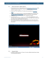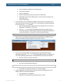
1
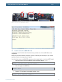
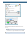
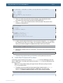
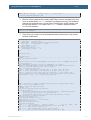
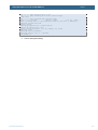
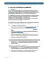
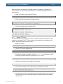
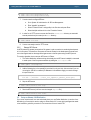
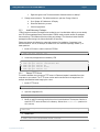
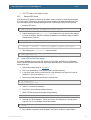
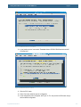
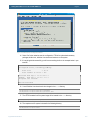
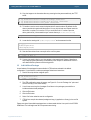
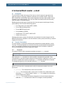
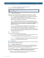
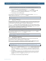
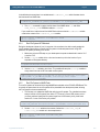
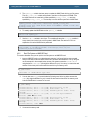
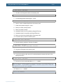
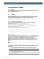
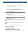
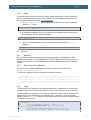
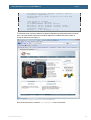
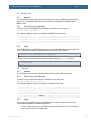
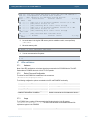
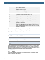
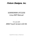
LPC3250 – Getting Started with Linux
Copyright 2009 © Embedded Artists AB
Getting Started With
Linux on the
LPC3250 OEM Board
Getting Started With Linux on the LPC3250 OEM Board
Page 2
Embedded Artists AB
Södra Promenaden 51
SE-211 38 Malmö
Sweden
[email protected]
http://www.EmbeddedArtists.com
Copyright 2009 © Embedded Artists AB. All rights reserved.
No part of this publication may be reproduced, transmitted, transcribed, stored in a retrieval system, or
translated into any language or computer language, in any form or by any means, electronic,
mechanical, magnetic, optical, chemical, manual or otherwise, without the prior written permission of
Embedded Artists AB.
Disclaimer
Embedded Artists AB makes no representation or warranties with respect to the contents hereof and
specifically disclaims any implied warranties or merchantability or fitness for any particular purpose.
Information in this publication is subject to change without notice and does not represent a
commitment on the part of Embedded Artists AB.
Feedback
We appreciate any feedback you may have for improvements on this document. Please send your
comments to [email protected].
Trademarks
All brand and product names mentioned herein are trademarks, services marks, registered
trademarks, or registered service marks of their respective owners and should be treated as such.
Copyright 2009 © Embedded Artists AB
Rev A
Getting Started With Linux on the LPC3250 OEM Board
Page 3
Table of Contents
1 Introduction ........................................................... 5
1.1
Organization of this Document ..................................................... 5
1.2
Conventions in This Book ............................................................. 5
2 Getting Started ...................................................... 6
2.1
Introduction .................................................................................... 6
2.2
Preparation and Setting up the Board .......................................... 6
2.3
Load the u-boot From MMC/SD Card ............................................ 7
2.4
Load the u-boot From UART ......................................................... 8
2.5
Boot the u-boot............................................................................... 9
2.6
Load the Root File System and Linux Kernel ............................ 10
3 Using the Linux Target Image Builder .............. 13
3.1
Introduction .................................................................................. 13
3.2
Setting up a Fedora 11 Distribution ............................................ 13
3.2.1
Download and Start the VMware Appliance ................................ 13
3.2.2
Customize Fedora and Setup a New User .................................. 14
3.2.3
Install Necessary Packages ........................................................ 15
3.2.4
Setup a TFTP Server .................................................................. 16
3.2.5
Setup a NFS Server .................................................................... 17
3.3
Setup an Ubuntu 9.04 Distribution.............................................. 17
3.3.1
Download and Start the VMware Appliance ................................ 18
3.3.2
Customize Ubuntu ....................................................................... 18
3.3.3
Install Necessary Packages ........................................................ 20
3.3.4
Setup a TFTP Server .................................................................. 20
3.3.5
Setup an NFS Server .................................................................. 21
3.4
Install LTIB and Build the Images ............................................... 21
3.5
Add Additional Packages ............................................................ 24
3.6
Useful Linux Commands ............................................................. 25
3.6.1
3.7
Obtain IP Address ....................................................................... 25
Hello World Application ............................................................... 25
4 Universal Boot Loader - u-boot ......................... 26
4.1
Introduction .................................................................................. 26
4.2
Console / Environment ................................................................ 26
4.2.1
Commands .................................................................................. 26
4.2.2
Network Related Variables .......................................................... 27
4.2.3
Boot Related Variables ................................................................ 27
4.3
Copyright 2009 © Embedded Artists AB
Booting Options ........................................................................... 27
4.3.1
Kernel from USB Memory Stick ................................................... 27
4.3.2
Kernel from TFTP Server ............................................................ 28
4.3.3
Kernel Stored in NAND Flash ...................................................... 28
4.3.4
Root File System NFS Mounted .................................................. 29
Rev A
Getting Started With Linux on the LPC3250 OEM Board
Page 4
4.3.5
Root File System in NAND Flash ................................................ 29
4.3.6
Root File System on MMC/SD Card ............................................ 30
4.4
Use DHCP...................................................................................... 32
4.5
Known Problems .......................................................................... 32
4.5.1
Unable to Access USB Memory Stick ......................................... 32
5 Peripherals and Drivers ...................................... 33
5.1
Introduction .................................................................................. 33
5.2
Display .......................................................................................... 33
5.2.1
Hardware ..................................................................................... 33
5.2.2
Device Driver and Configuration .................................................. 33
5.2.3
Usage .......................................................................................... 33
5.2.4
Add and Use the fbv Application ................................................ 33
5.3
Hardware ..................................................................................... 34
5.3.2
Device Driver and Configuration .................................................. 34
5.3.3
Usage .......................................................................................... 35
5.4
Network ......................................................................................... 35
5.4.1
Hardware ..................................................................................... 35
5.4.2
Device Driver and Configuration .................................................. 35
5.4.3
Usage .......................................................................................... 35
5.5
Memory Card ................................................................................ 37
5.5.1
Hardware ..................................................................................... 37
5.5.2
Device Driver and Configuration .................................................. 37
5.5.3
Usage .......................................................................................... 37
5.6
USB Host ....................................................................................... 37
5.6.1
Hardware ..................................................................................... 37
5.6.2
Device Driver and Configuration .................................................. 37
5.6.3
Usage .......................................................................................... 37
5.7
LEDs and Buttons ........................................................................ 38
5.7.1
Hardware ..................................................................................... 38
5.7.2
Device Driver and Configuration .................................................. 38
5.7.3
Usage .......................................................................................... 38
5.8
Copyright 2009 © Embedded Artists AB
Touch Screen................................................................................ 34
5.3.1
NAND Flash................................................................................... 39
5.8.1
Hardware ..................................................................................... 39
5.8.2
Device Driver and Configuration .................................................. 40
5.8.3
Usage .......................................................................................... 40
Rev A
Getting Started With Linux on the LPC3250 OEM Board
Page 5
1 Introduction
This document provides you with step-by-step instructions to get Linux up-and-running on the
LPC3250 OEM Board / LPC3250 Developer’s Kit. The instructions cover everything from building the
bootloader, kernel, root file system to transfer the built software to the target board.
Additional documentation you might need is.
•
LPC3250 OEM Board User’s Manual – This document is available for download at Embedded
Artists support site.
•
Kickstart and Stage 1 Loader – The LPC3250 OEM board has been preprogrammed with the
Kickstart and Stage 1 Loader (S1L). This document gives an introduction to these loaders.
Please note that the document has been written by NXP with a different LPC3250
Development board in mind. Not all information is relevant for Embedded Artists LPC3250
OEM Board. The document is found in the sample application package (CDL) that can be
downloaded from Embedded Artists support site. The location of the document within the
package is software/csps/lpc32xx/bsps/ea3250/docs/lpc32xx_bl.pdf.
1.1
1.2
Organization of this Document
•
Chapter 2 – Getting Started
This chapter describes how you quickly get Linux up-and-running on the LPC3250 OEM
Board using prebuilt u-boot, Linux kernel and root file system images.
•
Chapter 3 – Using the Linux Target Image Builder
This chapter describes how the Linux Target Image Builder (LTIB) is setup and used on a
Fedora 11 and Ubuntu 9.04 distribution.
•
Chapter 4 – Universal Boot Loader - u-boot
This chapter describes the u-boot and how to use different booting options.
•
Chapter 5 – Peripherals and Drivers
This chapter describes some of the peripherals and drivers that are available on the LPC3250
OEM Board.
Conventions in This Book
A number of conventions have been used throughout the book to help the reader better understand the
content of the book.
Constant width text – is used for file system paths and command, utility and tool names.
$ This field illustrates user input in a terminal running on the
development workstation, i.e., on the workstation where you edit,
configure and build Linux
# This field illustrates user input on the target hardware, i.e.,
input given to the terminal attached to the LPC3250 OEM Board
This field is used to illustrate example code or excerpt from a
document.
Copyright 2009 © Embedded Artists AB
Rev A
Getting Started With Linux on the LPC3250 OEM Board
Page 6
2 Getting Started
2.1
Introduction
This chapter describes how you get-up-and running with prebuilt images of the u-boot, Linux kernel
and root file system. Necessary images can be downloaded from Embedded Artists support site or you
can follow the instructions in chapter 3 to build the images yourself.
•
u-boot.bin – The Universal Bootloader, known as u-boot for short.
•
uImage – The Linux kernel image.
•
rootfs.jffs2 – A JFFS2 formatted root file system to be stored in NAND flash.
Besides the images you will also need a USB memory stick and an MMC/SD card (if you select to
load the u-boot from a MMC/SD card) in order to follow the instructions below. A terminal application
is also required as an interface towards the board. These instructions will be using the Tera Term
terminal application.
2.2
Preparation and Setting up the Board
In this section you will setup the board and boot into the Stage 1 boot loader (S1L) where it will then be
possible to load the u-boot.
1. Copy the u-boot.bin file to the root directory in a FAT formatted MMC/SD card.
2. Copy the uImage and rootfs.jffs files to the root directory of a USB memory stick.
3. Insert the MMC/SD card in the MMC/SD card slot on the QVGA Base board, see Figure 1.
4. Insert the USB memory stick in the USB A connector, see Figure 1.
5. Connect the USB cable that came with the board to the USB mini-B connector marked UART
#0, see Figure 1. Also make sure that the cable is connected to your computer.
6. The board will now power up. Follow the instructions in the User’s Manual for the LPC3250
OEM Board to install necessary FTDI USB drivers and identify which COM port that was
assigned to the board.
7. Start your terminal application and connect to the COM port associated with the board.
Note: Make sure the automatic ISP jumpers (marked RST and P2.10 on the base board)
are open. If not it’s possible that a terminal application resets the board. In Figure 1 the
jumpers are closed.
8. Reset the board by pressing the Reset button. The S1L bootloader will boot, see Figure 2 to
see what it looks like in Tera Term.
9. You are now ready to continue to the next section and load the u-boot.
Copyright 2009 © Embedded Artists AB
Rev A
Page 7
Getting Started With Linux on the LPC3250 OEM Board
4
3
5
Figure 1 Top Part of the QVGA Base Board
Figure 2 S1L Bootloader Console
2.3
Load the u-boot From MMC/SD Card
In this section you will load the u-boot from the memory card and store it in the NAND flash on the
target board.
Make sure you have followed the instructions in section 2.2 and that you have output in your terminal
application similar to the output shown in Figure 2.
If you don’t have access to an MMC/SD card go to section 2.4 and load the u-boot from UART instead.
1. Load the u-boot.bin file from the MMC/SD card to SDRAM at address 0x83fa0000.
EA3250> load blk u-boot.bin raw 0x83fa0000
2. Save the image to the NAND flash.
EA3250> nsave
3. Setup the S1L bootloader to automatically load the u-boot.
EA3250> aboot flash raw 0x83fa0000
Copyright 2009 © Embedded Artists AB
Rev A
Getting Started With Linux on the LPC3250 OEM Board
Page 8
4. Set the boot delay to 2 seconds (the system prompt must be set at the same time).
EA3250> prompt EA3250> 2
2.4
Load the u-boot From UART
In this section you will load the u-boot from UART and store it in the NAND flash on the target board.
Make sure you have followed the instructions in section 2.2 and that you have output in your terminal
application similar to the output shown in Figure 2.
1. Tell S1L to load from the UART to SDRAM at address 0x83fa0000.
EA3250> load term raw 0x83fa0000
2. In Tera Term Select the File Send File menu alternative.
3. Locate and select your u-boot.bin file. Make sure the “Binary” option is selected, see Figure 3.
A dialog will appear showing the progress when you have clicked the “Open” button, see
Figure 4.
4. When the file has been transferred send a Break sequence with ALT-b to get back to the
EA3250> prompt.
5. Save the image to the NAND flash.
EA3250> nsave
6. Setup the S1L bootloader in order to automatically load the u-boot.
EA3250> aboot flash raw 0x83fa0000
7. Set the boot delay to 2 seconds (the system prompt must be set at the same time).
EA3250> prompt EA3250> 2
8. You are now ready to boot the u-boot.
Copyright 2009 © Embedded Artists AB
Rev A
Getting Started With Linux on the LPC3250 OEM Board
Page 9
Figure 3 Send File via Tera Term
Figure 4 Transfer progress in Tera Term
2.5
Boot the u-boot
The u-boot has been loaded to the target and saved in the NAND flash. It is now time to boot and
setup the u-boot.
1. Issue the boot command to start u-boot.
EA3250> boot
2. The u-boot will now start and you will see something similar to the output below. Hit any key
to stop the u-boot from auto booting.
U-Boot 2009.03-rc1 (Sep 27 2009 - 14:27:25)
DRAM:
NAND:
Copyright 2009 © Embedded Artists AB
64 MB
128 MiB
Rev A
Page 10
Getting Started With Linux on the LPC3250 OEM Board
*** Warning - bad CRC or NAND, using default environment
In:
serial
Out:
serial
Err:
serial
Hit any key to stop autoboot:
uboot>
0
3. There is no need to worry about the warning message. It just means that the u-boot
environment hasn’t been saved to persistent storage (NAND flash).
4. Enter print in the u-boot console to see the u-boot environment. Only a portion of the
variables are displayed below.
uboot> print
bootargs=
bootcmd=run mtdboot
...
ethaddr=00:1a:f1:00:00:00
ipaddr=192.168.5.234
serverip=192.168.5.88
rootpath=/home/user/ltib/rootfs
...
5. In order to test the network functionality in Linux you need to change the ipaddr variable to
an IP address that is valid on your network. In this example we assume that 192.168.0.100 is
valid on your network (change it to an address that really is valid on your network).
uboot> setenv ipaddr 192.168.0.100
6. Now save your changes done to the environment. This will also remove the warning message
from step 2.
uboot> saveenv
7. Continue to the next section where you will load the root file system and Linux kernel.
2.6
Load the Root File System and Linux Kernel
In this section you will load the root file system (rootfs.jffs2) from the USB memory stick and
store it in NAND flash. You will then also load the Linux kernel (uImage) from the USB memory stick
and boot the kernel.
Note: If you have problems loading the images from the USB memory stick go to section
4.5.1 for a possible solution.
1. The default u-boot environment has been prepared with a variable named update_fs
which will load the root file system and store it in NAND flash. The content of the
update_fs variable is explained in section 4.3.5, for now just run the command.
uboot> run update_fs
...
Copyright 2009 © Embedded Artists AB
Rev A
Getting Started With Linux on the LPC3250 OEM Board
Page 11
NAND write: device 0 offset 0x500000, size 0x400000
4194304 bytes written: OK
2. When the root file system has been stored in NAND Flash it is time to load and boot the Linux
kernel. A variable named mtdboot is available in the default environment. This variable will
setup the boot arguments to use a root file system in NAND flash (in an MTD partition), load
the kernel and then boot it. The content of the mtdboot variable is explained in section
4.3.5. Run the command:
uboot> run mtdboot
3. There will be a lot of output in the terminal application when the kernel boots. Only a portion
has been included below.
## Booting kernel from Legacy Image at 80100000 ...
Image Name:
Linux-2.6.27.8
Image Type:
ARM Linux Kernel Image (uncompressed)
Data Size:
1602272 Bytes = 1.5 MB
Load Address: 80008000
Entry Point: 80008000
Verifying Checksum ... OK
Loading Kernel Image ... OK
OK
Starting kernel ...
Uncompressing
Linux...........................................................................
done, booting the kernel.
ÿLinux version 2.6.27.8 (user@bagvapp) (gcc version 3.4.5) #1 PREEMPT Mon Sep 28
09:51:45 CEST 2009
CPU: ARM926EJ-S [41069264] revision 4 (ARMv5TEJ), cr=00053177
Machine: Embedded Artists LPC3250 OEM board with the LPC3250 Microcontroller
Memory policy: ECC disabled, Data cache writeback
CPU0: D VIVT write-back cache
CPU0: I cache: 32768 bytes, associativity 4, 32 byte lines, 256 sets
CPU0: D cache: 32768 bytes, associativity 4, 32 byte lines, 256 sets
Built 1 zonelists in Zone order, mobility grouping on. Total pages: 16256
Kernel command line: root=/dev/mtdblock3 rw rootfstype=jffs2 ip=192.168.5.234
ea_ethaddr=00:1a:f1:00:00:00 console=ttyS0,115200n8
...
mmc0: host does not support reading read-only switch. assuming write-enable.
mmc0: new SD card at address e624
mmcblk0: mmc0:e624 SU256 247040KiB
mmcblk0: p1
IP-Config: Guessing netmask 255.255.255.0
IP-Config: Complete:
device=eth0, addr=192.168.5.234, mask=255.255.255.0, gw=255.255.255.255,
host=192.168.5.234, domain=, nis-domain=(none),
bootserver=255.255.255.255, rootserver=255.255.255.255, rootpath=
VFS: Mounted root (jffs2 filesystem).
Freeing init memory: 100K
init started: BusyBox v1.11.2 ()
starting pid 296, tty '': '/etc/rc.d/rcS'
Mounting /proc and /sys
Setting the hostname to nxp
Mounting filesystems
scsi 0:0:0:0: Direct-Access
SanDisk Cruzer
8.02 PQ: 0 ANSI: 0 CCS
sd 0:0:0:0: [sda] 15704063 512-byte hardware sectors (8040 MB)
sd 0:0:0:0: [sda] Write Protect is off
sd 0:0:0:0: [sda] Assuming drive cache: write through
sd 0:0:0:0: [sda] 15704063 512-byte hardware sectors (8040 MB)
Copyright 2009 © Embedded Artists AB
Rev A
Getting Started With Linux on the LPC3250 OEM Board
Page 12
sd 0:0:0:0: [sda] Write Protect is off
sd 0:0:0:0: [sda] Assuming drive cache: write through
sda: sda1
sd 0:0:0:0: [sda] Attached SCSI removable disk
scsi 0:0:0:1: CD-ROM
SanDisk Cruzer
8.02 PQ: 0 ANSI: 0
mount: mounting usbfs on /proc/bus/usb failed: No such file or directory
Starting syslogd and klogd
Running sysctl
Setting up networking on loopback device:
Setting up networking on eth0:
/etc/rc.d/init.d/network: line 149: udhcpc: not found
Starting inetd:
Starting the boa webserver:
starting pid 359, tty '': '-/bin/sh'
[root@nxp /]#
4. Linux is now up-and-running.
Copyright 2009 © Embedded Artists AB
Rev A
Getting Started With Linux on the LPC3250 OEM Board
Page 13
3 Using the Linux Target Image Builder
3.1
Introduction
The Linux Target Image Builder (LTIB) system will be used to build the u-boot, Linux kernel and root
file system. LTIB ease the build and deployment process of several components needed in a Linux
system. Besides the bootloader and kernel a lot of needed utilities, modules and libraries are included
and will be configured and built automatically by LTIB. For more information about LTIB, go to
http://ltib.org.
This chapter describes how you install LTIB and all necessary packages in a Linux distribution (setting
up Fedora 11 and Ubuntu 9.04 is explained). It will be explained how you can download the Linux
distributions as VMware virtual appliances and run it in a VMware Player.
Even though you are an experienced user and don’t intend to run Fedora 11 or Ubuntu 9.04 you will
find information about, for example, packages that are needed by LTIB.
3.2
Setting up a Fedora 11 Distribution
If you are an experienced Linux user and already have your own Fedora distribution (or another Linux
distribution) you can skip this section and go to either section 3.2.3 to see which packages that needs
to be installed or directly to section 3.4 for instructions of how to install LTIB.
3.2.1
Download and Start the VMware Appliance
1. Download Fedora 11 as a VMware appliance from http://www.bagside.com/bagvapp. When
writing this document it was packed in a 7-Zip compressed file named f11.7z.
2. You also need 7-Zip to unpack the file. You can download this utility from http://www.7zip.org.
3. In order to use the VMware appliance you need to install VMware Player. Download it from
http://www.vmware.com/products/player/ and follow the instructions to install the player.
4. Unpack the f11.7z file in a location of your choice.
5. By default this appliance has been setup to run NAT based Ethernet interface. This won’t
work since we would like to connect to the appliance using TFTP and NFS. Locate the file
named fed11.vmx and open that file in a text editor.
6. Locate the row specified below in the fed11.vmx file.
ethernet0.connectionType = "nat"
7. Change from “nat” to “bridged” and save the file (Note: from version 2.5.x of the VMware
Player it is possible to do these changes from within the VMware Player menu instead of
modifying the vmx file).
ethernet0.connectionType = "bridged"
8. Now double-click the fed11.vmx file to start the VMware Player. If vmx files haven’t been
associated with VMware Player you can start VMware Player manually and then select the
Open command and browse to the vmx file.
9. When Fedora has started you will see a Login dialog where you can select which user to
login, see Figure 5. Choose the bagside user and enter “bagside” as password.
Copyright 2009 © Embedded Artists AB
Rev A
Getting Started With Linux on the LPC3250 OEM Board
Page 14
Figure 5 Fedora Login Screen
3.2.2
Customize Fedora and Setup a New User
1. By default the keyboard layout is a US Layout. If you have a different keyboard layout change
it like this:
a. Go to the System Preferences Keyboard menu.
b. Click on the Layouts tab.
c. Click the “Add” button.
d. Select your keyboard layout (country) and click the “Add” button.
e. Select which layout to be the default layout. You can also remove the layouts you
don’t intend to use.
f.
Click the “Close” button.
2. To have consistent instructions throughout this manual we will create a new user named
“user”. If you don’t perform this step make sure to exchange the user “user” for whichever
user you are using in all instructions.
a. Open a terminal application (not the same type of application as Tera Term):
Applications System Tools Terminal.
b. Run the adduser command in the terminal. You need to use the sudo command
to get administrator privileges and will be asked for a password. The password for
your current user is “bagside”.
$ sudo adduser user
Copyright 2009 © Embedded Artists AB
Rev A
Getting Started With Linux on the LPC3250 OEM Board
Page 15
c. Give a new password to the user “user” by using the passwd command. Select the
password of your choice (a password you will remember).
$ sudo passwd user
3. Now we also need to give administrator rights to this user and also prepare rights needed by
LTIB.
a. Start the visudo tool to edit the sudoers file (where rules are specified).
$ sudo visudo
b. The sudoers file will be opened. Locate the lines that looks like below.
root
bagside
ALL=(ALL)
ALL=(ALL)
ALL
ALL
c. Press the ‘i’ key on your keyboard to enter insert mode and add the lines below after
the line starting with “bagside”. The second line is needed by LTIB and means that
no password will be requested when using the rpm command.
user
user
ALL=(ALL)
ALL=(ALL)
ALL
NOPASSWD: /bin/rpm, /opt/ltib/usr/bin/rpm
d. Press the ESC key on your keyboard to exit insert mode.
e. Enter “:wq” to save your changes and exit visudo.
:wq
4. Now you need to login as the new user.
a. Go to System Log out.
b. Click the “Log Out” button.
c. When you are at the Login dialog select “user” and enter the password you selected
in step 2 to login “user”.
5. When you have logged in as “user” you probably need to change the keyboard layout for this
user as described in step 1 above.
6. Since a terminal application is used often it is convenient to add shortcuts to this application.
a. Go to Applications System Tools.
b. Right-click on Terminal and select “Add this launcher to panel”.
c. Right-click again on Terminal and select “Add this launcher to desktop”.
3.2.3
Install Necessary Packages
LTIB will require a number of packages to be installed in your Linux distribution before you can actually
use LTIB. If these packages haven’t been installed LTIB will usually complain and list the packages
that are missing. LTIB could also fail without listing any package. The instructions below install the
packages that are missing in the Fedora distribution we are using.
Copyright 2009 © Embedded Artists AB
Rev A
Getting Started With Linux on the LPC3250 OEM Board
Page 16
Please note that we don’t display the output and progress of an installation of a package in the
instructions below. You will, for example, be asked if it is ok to download a package. Answer ‘y’ on
these questions.
1. Install a CVS client in order to checkout LTIB files.
$ sudo yum install cvs
2. LTIB is using Perl and need some Perl related modules.
$ sudo yum install perl-libwww-perl
$ sudo yum install perl-ExtUtils-MakeMaker
3. A few other packages are also needed by LTIB.
$
$
$
$
$
$
sudo
sudo
sudo
sudo
sudo
sudo
3.2.4
yum
yum
yum
yum
yum
yum
install
install
install
install
install
install
tcl
zlib-devel
rpm-build
ncurses-devel
bison
gettext
Setup a TFTP Server
This section describes how you setup a TFTP server in Fedora and makes it accessible from other
computers on your network. The TFTP server can be used to transfer files to the target board, for
example, download the kernel image by the u-boot.
1. Install a TFTP server.
$ sudo yum install tftp-server
2. Open the TFTP server configuration file.
$ sudo gedit /etc/xinetd.d/tftp &
3. The file will be opened in a text editor. Locate the server_args variable which contains
the directory that will be used as a root directory by the TFTP server.
server_args
= -s /var/lib/tftpboot
4. Change it to use the user’s home directory as root directory.
server_args
= -s /home/user
5. Now it is time to enable the TFTP server. Run the commands below to do this.
$ sudo /sbin/chkconfig tftp on
$ sudo /sbin/service xinetd start
6. By default Fedora has setup strict firewall rules that may prohibit access to the TFTP server
over the network. We take a pretty drastic approach in these instructions and completely
disable iptables.
Copyright 2009 © Embedded Artists AB
Rev A
Getting Started With Linux on the LPC3250 OEM Board
Page 17
$ sudo /etc/init.d/iptables stop
$ sudo /etc/init.d/ip6tables stop
7. You also need to configure SELinux.
a. Go to System Administration SELinux Management.
b. Enter “bagside” as password.
c. Select “Process Domain” and type tftp in the filter box and press Enter.
d. Select the tftpd and then click on the “Permissive” button.
8. In order for the TFTP server to access the files in the /home/user directory we must add
execute permissions (list content) to the user directory.
$ cd /home
$ sudo chmod a+x user
9. You are now ready to use the TFTP server.
3.2.5
Setup a NFS Server
An NFS (network file system) mounted root file system is quite convenient to use during development
of a Linux system. The actual root file system will then be located on the development computer and
not on the target board, but the target board gets access to the file system using the NFS protocol.
This section describes how to setup an NFS server in Fedora.
1. The Fedora distribution we are working with already has an NFS server installed, but we need
to make a part of the file system accessible by editing the /etc/exports file.
$ sudo gedit /etc/exports
2. Add the following line to the opened file (note that it is only one line). Also note that if you are
not using the 192.168.x.x network (IP addresses in this address range) you need to change
this part of the line.
/home/user/ltib/rootfs
192.168.0.0/255.255.0.0(rw,no_root_squash,no_subtree_check,sync)
3. Stop the NFS server.
$ sudo /sbin/service nfs stop
4. Start the NFS server (it will now use the changed exports file).
$ sudo /sbin/service nfs start
3.3
Setup an Ubuntu 9.04 Distribution
If you are an experienced Linux user and already have your own Debian distribution (or another Linux
distribution) you can skip this section and go to either section 3.3.3 to see which packages that needs
to be installed or go directly to section 3.4 for instructions of how to install LTIB.
Copyright 2009 © Embedded Artists AB
Rev A
Getting Started With Linux on the LPC3250 OEM Board
3.3.1
Page 18
Download and Start the VMware Appliance
1. Download Ubuntu 9.04 as a VMware appliance from http://chrysaor.info/?page=ubuntu. When
writing this document it was packed in a tar-gz compressed file named
ubuntu904desktop.tgz.
2. You can use 7-Zip to unpack the file. This utility can be downloaded from http://www.7zip.org.
3. In order to use the VMware appliance you need to install VMware Player. Download it from
http://www.vmware.com/products/player/ and follow the instructions to install the player.
4. Unpack the ubuntu904desktop.tgz file in a location of your choice.
5. Now double-click the ubuntu904desktop.vmx file to start the VMware Player. If vmx
files haven’t been associated with VMware Player you can start VMware Player manually and
then select the Open command and locate the vmx file.
6. When Ubuntu has started you will see a Login dialog where you can choose which user to
login, see Figure 6. Enter “user” (without quotation marks) as the user and “chrysaor.info” as
the password.
Figure 6 Ubuntu Login Screen
3.3.2
Customize Ubuntu
1. By default the keyboard layout is a US Layout. If you have a different keyboard layout change
it by following these instructions.
Copyright 2009 © Embedded Artists AB
Rev A
Getting Started With Linux on the LPC3250 OEM Board
Page 19
a. Go to the System Preferences Keyboard menu.
b. Click on the Layouts tab.
c. Click the “Add” button.
d. Select your keyboard layout (country) and click the “Add” button.
e. Select which layout to be the default layout. You can also remove the layouts you
don’t intend to use.
f.
Click the “Close” button.
2. A user with name “user” has already been added to the system which means that we don’t
have to add this user as was done in section 3.2.2. If you would like to change the password
for this user, use the passwd command.
a. Open a terminal application (note the same kind of application as Tera Term) from
Applications Accessories Terminal.
b. Run the passwd command as illustrated below and enter the password of your
choice when asked for it (note that when using sudo you might first be asked for the
current password which is “chrysaor.info” without the quotation marks).
$ sudo passwd user
3. Make sure you have network access by activating the network device in VMware Player. It
should be connected and of type “Bridged” as can be seen in Figure 7.
Figure 7 Activate Network Device
4. The user “user” has been added to the admin group which by default has been given
administrative rights in the sudoers file. LTIB requires additional rights to be added for this
user; more specifically a password may not be requested when using the rpm command.
a. Start the visudo tool to edit the sudoers file.
$ sudo visudo
b. At the end of the file add the following line.
user
ALL=(ALL)
NOPASSWD:/usr/bin/rpm, /opt/ltib/usr/bin/rpm
c. Press CTRL+X to exit the file. Choose ‘Y’ to save the changes.
5. A terminal application is used often and it is therefore convenient to add shortcuts on the
desktop and panel for the terminal application.
a. Go to Applications Accessories.
b. Right-click on Terminal and select “Add this launcher to panel”.
Copyright 2009 © Embedded Artists AB
Rev A
Page 20
Getting Started With Linux on the LPC3250 OEM Board
c. Right-click again on the Terminal and select “Add this launcher to desktop”.
6. Change screen resolution. The default resolution is quite low. Change it like this:
a. Go to System Preferences Display.
b. Select the Resolution you want.
c. Click the Apply button.
3.3.3
Install Necessary Packages
LTIB will require a number of packages to be installed in your Linux distribution before you can actually
use LTIB. If these packages haven’t been installed LTIB will usually complain and list the packages
that are missing. LTIB could also fail without listing any package. The instructions below install the
packages that are missing in the Ubuntu distribution we are using.
Please note that we don’t display the output and progress of an installation of a package in the
instructions below. You will, for example, be asked if it is ok to download a package. Answer ‘y’ on
these questions.
1. Install a CVS client in order to checkout LTIB files.
$ sudo apt-get install cvs
2. A few other packages are also needed by LTIB
$
$
$
$
$
sudo
sudo
sudo
sudo
sudo
3.3.4
apt-get
apt-get
apt-get
apt-get
apt-get
install
install
install
install
install
rpm
libncurses5-dev
m4
bison
tcl
Setup a TFTP Server
This section describes how you setup a TFTP server in Fedora and makes it accessible from other
computers on your network. The TFTP server can be used to transfer files to the target board, for
example, download the kernel image by the u-boot.
1. Install a TFTP server.
$ sudo apt-get install tftpd
2. Open the configuration file.
$ sudo gedit /etc/inetd.conf
3. Modify (or add if it is missing) the tftp line so that it looks like below. The last part of the line is
where the TFTP server will have its root directory. We set this to /home/user (note that it is
all in one row).
tftp dgram
/home/user
udp
wait
nobody
/usr/sbin/tcpd
/usr/sbin/in.tftpd
4. Restart inetd.
$ sudo /etc/init.d/openbsd-inetd restart
Copyright 2009 © Embedded Artists AB
Rev A
Getting Started With Linux on the LPC3250 OEM Board
Page 21
5. The TFTP server is now ready to be used.
3.3.5
Setup an NFS Server
An NFS (network file system) mounted root file system is quite convenient to use during development
of a Linux system. The actual root file system will then be located on the development computer and
not on the target board, but the target board gets access to the file system using the NFS protocol.
1. Install the NFS server.
$ sudo apt-get install portmap nfs-kernel-server
2. Add the following line to the /etc/exports file (note that it is only one line). Also note that
if you are not using the 192.168.x.x network (IP addresses in this address range) you need to
change this part of the line.
$ sudo gedit /etc/exports
/home/user/ltib/rootfs
192.168.0.0/255.255.0.0(rw,no_root_squash,no_subtree_check,sync)
3. After setting up the /etc/exports, export the shares.
$ sudo exportfs -ra
3.4
Install LTIB and Build the Images
This section describes how you install LTIB, selects the configuration applicable for the Embedded
Artists LPC3250 OEM Board and starts the build process where the u-boot, Linux kernel and root file
system will be built.
1. Open a web browser and go to http://ltib.org.
2. Click on the Download link in the left menu (below the Resources title).
3. In the “Quick install” section you will find a link to the netinstall.txt file. Right-click on this file
and save it in your home directory (/home/user).
4. Open up a terminal application and run the netinstall script.
$ cd /home/user
$ perl netinstall.txt
5. Select ‘Y’ to continue the installation.
6. Click Enter to use the default installation directory.
7. When LTIB files have been downloaded change directory.
$ cd ltib
8. Now start the LTIB configuration. The first time you run the configuration it will take quite a
long time since a lot of packages must be downloaded.
$ ./ltib
9. After a while a configuration menu will appear, see Figure 8. Hit Enter to select Platform.
Copyright 2009 © Embedded Artists AB
Rev A
Getting Started With Linux on the LPC3250 OEM Board
Page 22
Figure 8 LTIB Platform Selections Menu
10. In the “platform choice” menu select “Embedded Artists LPC3250 OEM Board with the NXP
LPC32XX SoC”.
Figure 9 LTIB Platform Choice Menu
11. Click the “Exit” button.
12. Select “Yes” when asked to save the configuration.
13. A new configuration menu will appear, see Figure 10. For now just click the Exit button and go
with the default configuration.
Copyright 2009 © Embedded Artists AB
Rev A
Getting Started With Linux on the LPC3250 OEM Board
Page 23
Figure 10 LTIB Platform Configuration Menu
14. Select “Yes” when asked to save the configuration. LTIB will now download necessary
packages, build u-boot, build the Linux kernel and create a root file system.
15. If everything builds successfully you will have something similar to the example below in your
terminal.
…
Filesystem stats, including padding:
Total size
= 9160k
Total number of files = 455
Started: Wed Sep 30 15:39:38 2009
Ended:
Wed Sep 30 15:46:01 2009
Elapsed: 383 seconds
Build Succeeded
16. You will find the Linux kernel and u-boot images in the boot directory.
/home/user/ltib/rootfs/boot/uImage
/home/user/ltib/rootfs/boot/u-boot.bin
17. The JFFS2 formatted root file system image will be located in the ltib directory.
/home/user/ltib/rootfs.jffs2
18. The complete root file system is located in the following directory.
/home/user/ltib/rootfs/
Copyright 2009 © Embedded Artists AB
Rev A
Getting Started With Linux on the LPC3250 OEM Board
Page 24
19. Copy the images to the /home/user directory ensuring that they are accessible by the TFTP
server.
$ cp /home/user/ltib/rootfs/boot/uImage /home/user
$ cp /home/user/ltib/rootfs/boot/u-boot.bin /home/user
$ cp /home/user/ltib/rootfs.jffs2 /home/user
20. To be able to use the touch screen the device table file must be altered. By default this file
does not enable the input/eventX device files. You can skip this step and instead create the
device files in runtime. Go to section 5.3 if you would like to do it in runtime. Open the
device_table.txt file (it is assumed that your current directory is /home/user/ltib).
$ gedit bin/device_table.txt
21. Locate the line starting with “#/dev/input/event” and uncomment that line
# Input
#/dev/input/mice
/dev/input/event
22. Save the file and then force a recompile of the root file system.
$ ./ltib –p dev -f
23. You are now ready to deploy your Linux system to the target board. Chapter 2 describes a
way of deploying the system using a USB memory stick. Chapter 4 describes the u-boot in
more detail and also presents more booting options.
3.5
Add Additional Packages
A small subset of the packages that are available in LTIB has been selected in the default
configuration. If you would like to add more packages follow these instructions.
1. Run the ltib script with the configure option.
$ cd /home/user/ltib
$ ./ltib --configure
2. The LTIB configuration menu will appear, see Figure 10. Go to the “Package List” option and
hit the Enter key (or click Select button).
3. You will now see a long list of packages. Scroll down to the packages you would like to
include and select those packages.
4. Click the Exit button.
5. Click the Exit button.
6. Select “Yes” when asked to save the configuration.
7. LTIB will now compile the selected package and copy it (application or library) to the root file
system.
Please note that all the available packages have not been tested with the Linux port for the LPC3250
OEM Board. The build might even fail if components are missing.
Copyright 2009 © Embedded Artists AB
Rev A
Getting Started With Linux on the LPC3250 OEM Board
3.6
Page 25
Useful Linux Commands
3.6.1
Obtain IP Address
The IP address of your Linux host can be obtained by using the ifconfig command.
$ sudo ifconfig
3.7
eth1
Link encap:Ethernet HWaddr 00:0c:29:40:d2:db
inet addr:192.168.5.58 Bcast:192.168.5.255 Mask:255.255.255.0
inet6 addr: fe80::20c:29ff:fe40:d2db/64 Scope:Link
UP BROADCAST RUNNING MULTICAST MTU:1500 Metric:1
RX packets:732443 errors:0 dropped:0 overruns:0 frame:0
TX packets:202445 errors:0 dropped:0 overruns:0 carrier:0
collisions:0 txqueuelen:1000
RX bytes:418384275 (418.3 MB) TX bytes:57386301 (57.3 MB)
Interrupt:19 Base address:0x2024
lo
Link encap:Local Loopback
inet addr:127.0.0.1 Mask:255.0.0.0
inet6 addr: ::1/128 Scope:Host
UP LOOPBACK RUNNING MTU:16436 Metric:1
RX packets:78 errors:0 dropped:0 overruns:0 frame:0
TX packets:78 errors:0 dropped:0 overruns:0 carrier:0
collisions:0 txqueuelen:0
RX bytes:6040 (6.0 KB) TX bytes:6040 (6.0 KB)
Hello World Application
As a first step to application development in Linux you can try to use and modify the existing Hello
World application. Follow the steps below to access, modify and build the Hello World application.
1. Unpack and prepare the Hello World package
$ cd /home/user/ltib
$ ./ltib – p helloworld –m prep
2. Go to the directory where the Hello World application is available and open the source code.
$ cd rpm/BUILD/helloworld-1.1
$ gedit hello.c
3. Change the printf statement.
printf(“hello world from EA\n”)
4. Add the Hello World application to the list of packages that will be included in your Linux
system. Follow the instructions in section 3.5 and choose the package named “hello world”.
5. When the build has finished successfully transfer the root file system to the target board (with
an NFS mounted file system the application will be available directly after the build has
finished).
# hello
hello world from EA
Copyright 2009 © Embedded Artists AB
Rev A
Getting Started With Linux on the LPC3250 OEM Board
Page 26
4 Universal Boot Loader - u-boot
4.1
Introduction
The Universal Boot Loader also known as Das U-boot or u-boot for short is an open-source boot
loader that supports a wide range of different architectures such as ARM, PowerPC, XScale, x86,
MIPS, Coldfire, 68k, and MicroBlaze. Many board configurations have been made available, for each
architecture, by an active community. The u-boot boot loader has actually become the most widely
used boot loader on ARM based systems.
Besides supporting a wide range of architectures the u-boot also supports a wide range of booting
options. Below is a list of some of these booting options:
•
From Flash memory (for example NOR or NAND)
•
From a USB mass storage device
•
From an MMC/SD memory card
•
From a harddisk or CDROM
•
Using Ethernet: TFTP, BOOTP, DHCP or NFS
•
Using a serial connection
A booting option means a location from where the u-boot searches for the kernel image to load. If a
MMC/SD card has been selected the u-boot will initialize the memory card controller and try to read the
image(s) from that device.
4.2
Console / Environment
The u-boot supports a command line interface usually accessed via a terminal application, such as
Tera Term. The terminal application is connected to the serial port associated with the development
board. The command line interface allow you to manually type in boot commands or update the
environment variables that can later be used as boot options.
4.2.1
Commands
It is possible to discover which commands are available by using the help command.
uboot> help
When issuing the help command a list of all the available commands will be presented. These
commands are the ones that have been selected to be supported when configuring the u-boot. If more
information is needed about a specific command type help followed by the name of the command.
The example below gives you more information about the setenv command.
uboot> help setenv
Below is a list of some of the commands used to modify, list and execute variables in the u-boot
environment.
•
printenv – This command will print the u-boot environment.
•
setenv – This command is used to set the value of a variable. If the variable doesn’t exist
when calling setenv it will be created. If calling setenv on a variable, but not specifying a
value the variable will be deleted.
•
Copyright 2009 © Embedded Artists AB
saveenv – This command will save any changes done to the environment and must be
called after setenv has been used in order for the changes to be saved persistently.
Rev A
Getting Started With Linux on the LPC3250 OEM Board
Page 27
run – execute the commands found in an environment variable.
•
Below are examples of the commands described above.
uboot> setenv serverip 192.168.0.110
uboot> saveenv
uboot> run mtdboot
4.2.2
Network Related Variables
The u-boot environment contains a number of variables that are network related, i.e., related to
communication over a network. Make sure these variables are correctly setup for your network.
ethaddr – Specifies the Ethernet/MAC address that will be assigned to the development
board. The address will also be forwarded to the Linux kernel via the ea_ethaddr
•
argument in the boot argument list, sections 4.3.4, 4.3.5 and 4.3.6 contain example of its
usage. Make sure your board gets a unique address.
•
ipaddr – Specifies the IP address that will be assigned to the development board. The
address will be forwarded to the Linux kernel via the ip argument in the boot argument list,
sections 4.3.4, 4.3.5 and 4.3.6 contain example of its usage. Make sure this address is a valid
and unique address on your network. If you would like to use dynamically assigned IP
addresses see section 4.4.
•
serverip – This variable specifies the IP address of the TFTP server used when
downloading images using TFTP. Set it to the IP address of the computer running your TFTP
server. See section 3.6.1 for how to obtain the IP address in a Linux distribution.
netmask – Defines a mask used to divide your network into subnets. On most office and
•
home networks the netmask is set to 255.255.255.0 which means that the 3 first octets of the
IP address is fixed while the last can vary.
4.2.3
Boot Related Variables
The variables listed below are all related to the boot process.
•
bootargs – This variable contains the boot arguments sent to the Linux kernel. It usually
contains settings for the console and where to find the root file system.
•
bootcmd – This variable contains the boot command(s) that will be run during auto booting.
•
bootdelay – This variable defines the delay in seconds until an autoboot will take place.
Autoboot can be cancelled by hitting any key during boot.
4.3
Booting Options
Setting up a booting option means specifying from which source the Linux kernel should be loaded as
well as specifing where to find the root file system.
4.3.1
Kernel from USB Memory Stick
Most computers today have a USB connection and most operating systems support USB and have
device drivers for USB mass storage devices. This makes it simple to use a USB memory stick to
transfer boot images from the development computer to the development board.
For this purpose the usb and fatload commands are used to access the memory stick and transfer
the images to the development board. In the default environment there is a variable named
loadkernel_usb which illustrates how to load the kernel from a USB memory stick.
Note: If you have problems loading the images from the USB memory stick, please go to
section 4.5.1 and see if that solution solves your problem.
Copyright 2009 © Embedded Artists AB
Rev A
Getting Started With Linux on the LPC3250 OEM Board
Page 28
loadkernel_usb=usb start; fatload usb 0 $(loadaddr) uImage; usb stop
1. First the USB interface must be initialized with the usb start command.
2. Using the fatload command the kernel image (uImage) is then loaded via the USB
interface, device 0 and to the load address specified by the loadaddr variable.
3. The final step is to stop the USB interface.
If you would like to load the kernel from a USB memory stick make sure that the loadkernel
variable contains the content of the loadkernel_usb variable.
uboot> setenv loadkernel $(loadkernel_usb)
uboot> saveenv
4.3.2
Kernel from TFTP Server
During development of the Linux kernel it is convenient to use the Trivial File Transfer Protocol (TFTP)
to download a newly created kernel. The development cycle will be much shorter compared to when
you would need to copy the kernel image to, for example, a USB memory stick.
The tftpboot command is used when downloading images from a TFTP server. Before using this
command you have to make sure the network related variables described in section 4.2.2 are correctly
setup for your network. In the default environment there is a variable named loadkernel_tftp
which illustrates how to load the kernel from a TFTP server.
loadkernel_tftp=tftpboot $(loadaddr) uImage
If you would like to load the kernel from a TFTP server make sure that the loadkernel variable
contains the content of the loadkernel_tftp variable.
uboot> setenv loadkernel $(loadkernel_tftp)
uboot> saveenv
4.3.3
Kernel Stored in NAND Flash
The LPC3250 OEM Board comes with a large NAND flash that can host the Linux kernel for fast
access without the need for a USB memory stick or network access.
Before the kernel can be loaded from NAND flash the NAND flash must be updated with the kernel.
For this purpose the default environment has been setup with a variable named update_kernel.
update_kernel=run loadkernel; nand erase $(nand_kernel_off)
$(nand_kernel_sz); nand write.jffs2 $(loadaddr) $(nand_kernel_off)
$(nand_kernel_sz)
1. The loadkernel variable is used by the update_kernel variable to load the kernel to
SDRAM (address given by loadaddr). Section 4.3.1 and section 4.3.2 describe how the
loadkernel variable can be setup to load the kernel from either a USB memory stick or a
TFTP server.
2. The second step is to erase the part of the NAND flash that will be used to store the kernel.
The offset into the NAND flash as well as the maximum size of the kernel is given by the
variables nand_kernel_off and nand_kernel_sz.
3. The last step is to write the kernel image to NAND flash.
Copyright 2009 © Embedded Artists AB
Rev A
Getting Started With Linux on the LPC3250 OEM Board
Page 29
In the default environment there is a variable named loadkernel_nand which illustrates how to
load the kernel from NAND flash.
loadkernel_nand=nboot.jffs2 $(loadaddr) 0x0 $(nand_kernel_off)
1. The nboot command is used to load the kernel from NAND device 0x0 and offset
nand_kernel_off to SDRAM at address loadaddr.
If you would like to load the kernel from NAND flash make sure that the loadkernel variable
contains the content of the loadkernel_nand variable.
uboot> setenv loadkernel $(loadkernel_nand)
uboot> saveenv
4.3.4
Root File System NFS Mounted
During the development phase of your Linux system it is convenient to be able to easily update the
root file system without having to transfer the file system to the development board. Using NFS
(Network File System) will allow you to do this.
1. Make sure you have NFS setup on your development computer as described in section 3.2.5
or section 3.3.5.
2. Set the rootpath variable in the u-boot environment to point to the location of your
exported root file system directory.
rootpath=/home/user/ltib/rootfs
3. Use the nfsboot variable to boot Linux. This variable will setup the bootargs variable in
a way where Linux use an NFS mounted root file system.
nfsboot=setenv bootargs root=/dev/nfs rw nfsroot=$(serverip):$(rootpath)
ip=$(ipaddr) ea_ethaddr=$(ethaddr) console=ttyS0,115200n8;run
loadkernel;bootm $(loadaddr)
4.3.5
Root File System in NAND Flash
The root file system can be stored in the large NAND flash available on the LPC3250 OEM Board. This
is typically the place where the root file system will be placed after the development phase, allowing
the Linux system to be more stand-alone.
1. The first step is to update the NAND flash with the root file system. Two variables have been
setup to load the root file system from either a TFTP server or from a USB memory stick. If
you have problems loading the file system image from a USB memory stick, please read
section 4.5.1 to see if this solves your problem.
loadrootfs_tftp=tftpboot $(loadaddr) rootfs.jffs2
loadrootfs_usb=usb start;fatload usb 0 $(loadaddr) rootfs.jffs2;usb stop
2. Set the loadrootfs variable to the content of either the loadrootfs_tftp or
loadrootfs_usb variable as in the example below.
uboot> setenv loadrootfs $(loadrootfs_usb)
uboot> saveenv
Copyright 2009 © Embedded Artists AB
Rev A
Page 30
Getting Started With Linux on the LPC3250 OEM Board
3. The update_fs variable has been setup to update the NAND flash with the root file system.
First the loadrootfs variable will be used to load the root file system to SDRAM. Then
the NAND flash will be erased at the offset specified by nand_rootfs_off and size
specified by nand_rootfs_sz. The last step is to write the file system to the NAND flash.
update_fs=run loadrootfs; nand erase $(nand_rootfs_off)
$(nand_rootfs_sz); nand write.jffs2 $(loadaddr) $(nand_rootfs_off)
$(nand_rootfs_sz)
4. To actually update the NAND flash run the update_fs variable.
uboot> run update_fs
5. Use the mtdboot variable to boot Linux. This variable will setup the bootargs variable in
a way where Linux looks for the root file system in NAND flash. See section 5.8.2 for an
explanation of how the NAND flash is partitioned.
mtdboot=setenv bootargs root=/dev/mtdblock3 rw rootfstype=jffs2
ip=$(ipaddr) ea_ethaddr=$(ethaddr) console=ttyS0,115200n8; run
loadkernel;bootm $(loadaddr)
4.3.6
Root File System on MMC/SD Card
This section describes how you can put the root file system on an MMC/SD card.
1. Insert an MMC/SD card on your development computer. It will most likely be auto mounted
and you now need to discover which device file it has been associated with. First try using the
mount command. In the example below we see a file system mounted on /media/disk
using device file /dev/sde1 (this might be different for you). You can try to remove the card
and see if this mount point is removed to be sure this is your memory card.
$ sudo mount
...
/dev/sde1 on /media/disk type vfat
2. You can also use dmesg to locate the device file being used. In the log below we see that
sde1 (this might be different for you) is used. We also see that the size of the memory card
is about 500 MB which is correct for our card.
$ sudo dmesg
...
[171217.515649] sd 3:0:0:3:
[171217.515654] sd 3:0:0:3:
[171217.515657] sd 3:0:0:3:
through
[171217.521167] sd 3:0:0:3:
sectors: (507 MB/483 MiB)
[171217.528650] sd 3:0:0:3:
[171217.528653] sd 3:0:0:3:
[171217.528655] sd 3:0:0:3:
through
[171217.528713] sde: sde1
[sde] Write Protect is off
[sde] Mode Sense: 23 00 00 00
[sde] Assuming drive cache: write
[sde] 990976 512-byte hardware
[sde] Write Protect is off
[sde] Mode Sense: 23 00 00 00
[sde] Assuming drive cache: write
3. Un-mount the memory card.
Copyright 2009 © Embedded Artists AB
Rev A
Getting Started With Linux on the LPC3250 OEM Board
Page 31
$ sudo umount /dev/sde1
4.
Run fdisk to edit the partition table on the memory card.
$ sudo fdisk /dev/sde1
5. List the existing partition table using the p option.
Command (m for help): p
6. Use the d option to delete all partitions on the memory card.
7. Create a new partition using the n option.
8. Select p to create a primary partition.
9. Select 1 for partition number.
10. Use default value for the first cylinder by hitting the Enter key.
11. Use default value for last cylinder by hitting the Enter key.
12. Select w to write the new partition table to the memory card.
13. Format the memory card to an ext2 file system.
$ sudo mkfs.ext2 /dev/sde1
14. Mount the memory card when it has been formatted.
$ sudo mkdir /mnt/mmc
$ sudo mount –t auto /dev/sde1 /mnt/mmc
15. Copy the root file system to the memory card.
$ sudo cp R /home/user/ltib/rootfs/* /mnt/mmc
16. Un-mount the memory card, remove it from the development computer and insert it in the
development board.
$ sudo umount /dev/sde1
17. Boot into the u-boot console and add an mmcboot variable.
uboot> uboot> setenv mmcboot setenv bootargs root=/dev/mmcblk0p1
ip=\$(ipaddr) ea_ethaddr=\$(ethaddr) console=ttyS0,115200n8\;run
loadkernel\;bootm \$(loadaddr)
18. Run the mmcboot variable
uboot> run mmcboot
Copyright 2009 © Embedded Artists AB
Rev A
Getting Started With Linux on the LPC3250 OEM Board
4.4
Page 32
Use DHCP
If you don’t want to or are able to assign a static IP address to the target board you can instead use
dynamically assigned IP addresses by using the DHCP protocol. Please note that a DHCP server must
be available on your network.
In the u-boot you need to exchange the tftpboot command for the dhcp command to load the
images using DHCP. For the Linux kernel you need to set the ip argument to dhcp instead of using a
static IP address.
1. Boot into the u-boot console and change the ipaddr variable to dhcp.
uboot> setenv ipaddr dhcp
2. Change the loadkernel_tftp and loadrootfs_tftp variables.
uboot> setenv loadkernel_tftp dhcp $(loadaddr) uImage
uboot> setenv loadrootfs_tftp dhcp $(loadaddr) rootfs.jffs2
3. Update the loadkernel and loadrootfs variables.
uboot> setenv loadkernel $(loadkernel_tftp)
uboot> setenv loadrootfs $(loadrootfs_tftp)
uboot> saveenv
4. Boot Linux.
uboot> run bootcmd
4.5
Known Problems
4.5.1
Unable to Access USB Memory Stick
For some USB memory sticks you might need to specify which partition to use, not only which device
to use when invoking the fatload command. If this is the case for your memory stick and you are
using the default variables in the u-boot environment you need to update two variables;
loadkernel_usb and loadrootfs_usb.
In the example below the loadkernel_usb and the loadrootfs_usb variables are updated to
specify partition 0 on device 0. Please note how the backslash character needs to be used before the
semicolon when updating a variable.
uboot> setenv loadkernel_usb usb start\;fatload usb 0:0 $(loadaddr)
uImage\; usb stop
uboot> setenv loadrootfs_usb usb start\;fatload usb 0:0 $(loadaddr)
rootfs.jffs2\; usb stop
uboot> saveenv
You also need to make sure to update the loadkernel and loadrootfs variables.
uboot> setenv loadkernel $(loadkernel_usb)
uboot> setenv loadrootfs $(loadrootfs_usb)
uboot> saveenv
Copyright 2009 © Embedded Artists AB
Rev A
Page 33
Getting Started With Linux on the LPC3250 OEM Board
5 Peripherals and Drivers
5.1
Introduction
This chapter describes some of the peripherals on the LPC3250 OEM Board, their drivers and how to
use the peripherals from within Linux.
5.2
Display
5.2.1
Hardware
A 3.2 inch QVGA color TFT LCD display is mounted on the QVGA Base Board together with a
Solomon Systech SSD1289 LCD controller. The SSD1289 is attached to the SPI bus. The LPC3250
also has an embedded LCD controller which is compatible with the ARM PrimeCell PL110.
Both the SSD1289 and LPC3250 LCD controllers will be used. The SSD1289 will be used for initial
initialization of the display after a power-cycle of the display.
5.2.2
Device Driver and Configuration
The ARM PrimeCell PL110 device driver contains the majority of the code for the display and is
located here in the source tree: /drivers/video/amba-clcd.c.
The usage of the SSD1289 controller is located in the board specific file: /arch/machlpc32xx/board-ea3250.c. More specifically the clcd_enable callback will initialize the
display using the SSD1289 controller.
The configuration options below are related to the display functionality.
Configuration
Description
CONFIG_FB
Enable frame buffer support
CONFIG_FB_ARMCLCD
Enable the PL110 driver
5.2.3
Usage
The frame buffer is exposed to user space as a device file called /dev/fb0. It can be used directly
by an application to output graphics onto the display, for example, by memory mapping the file. A more
common way is to use a graphical API such as Microwindows, DirectFB or SDL instead.
By default, functionality called “console on framebuffer” and “Bootup Logo” has been enabled. This
means that you should see the Linux penguin in the top left corner of the display when you boot the
board.
You can also use the applications described in the touch screen section, see 5.3.3 to see usage of the
display.
5.2.4
Add and Use the fbv Application
The fbv application allows displaying images on a frame buffer. Supported image formats include png,
jpeg and bmp.
1. In your Linux distribution (for example Fedora 11 or Ubuntu 9.04) go to the ltib directory.
$ cd /home/user/ltib
2. Run the ltib script with the configure option.
$ ./ltib --configure
Copyright 2009 © Embedded Artists AB
Rev A
Page 34
Getting Started With Linux on the LPC3250 OEM Board
3. The LTIB configuration menu will appear, see Figure 10. Go to the “Package List” option and
hit the Enter key (or click Select button).
4. You will now see a long list of packages. Scroll down to the option called fbv and press
Spacebar on your keyboard to select the package.
5. Click the Exit button.
6. Click the Exit button.
7. Select “Yes” when asked to save the configuration.
8. LTIB will now compile the selected package and copy it (the application) to the root file
system.
9. Copy a picture to the root file system. Here we assume that you have an image named
pic.png in your home folder (/home/user/pic.png).
$ sudo cp /home/user/pic.png /home/user/ltib/rootfs/home/user
10. If you have an NFS mounted root file system the fbv application and picture will be
accessible from your Linux system.
11. Before displaying the image on the screen, make sure the display is enabled. It might have
been disabled for power save reasons.
# echo 0 > /sys/class/graphics/fb0/blank
12. Display the image on the LCD screen.
# fbv /home/user/pic.png
5.3
Touch Screen
5.3.1
Hardware
The touch screen controller mounted on the QVGA Base Board is a Texas Instruments TSC2046
which is a next-generation version to the ADS7846 controller. The TSC2046 is compatible with the
ADS7846.
The TSC2046 controller is a low-voltage controller connected to the SPI bus with low power
consumption and high speed (up to 125 kHz).
There is an embedded touch screen controller on the LPC3250 microcontroller, but that isn’t used with
the Embedded Artists LPC3250 OEM Board.
5.3.2
Device Driver and Configuration
A driver for the ADS7846 is integrated in the kernel and located here in the source tree:
/drivers/input/touchscreen/ads7846.c.
The following configuration options are related to the touch screen functionality.
Configuration
Description
CONFIG_INPUT_TOUCHSCREEN
Enable touch screen support
CONFIG_TOUCHSCREEN_ADS7846
Enable the ADS7846/TSC2046 driver
Copyright 2009 © Embedded Artists AB
Rev A
Page 35
Getting Started With Linux on the LPC3250 OEM Board
5.3.3
Usage
These instructions show how to use the touch screen through the tslib library. Tslib is an abstraction
layer for touch screen panel events, as well as a filter stack for the manipulation of those events, for
more information visit the tslib website: http://tslib.berlios.de/.
1. The /dev/input/event0 device node must be available. If it isn’t it can be created by
using the mknod utility.
# mknod /dev/input/event0 c 13 64
2. In the default configuration of the root file system tslib is included as well as calibration and
test applications. Run the calibration application.
# ts_calibrate
3. When you have calibrated the screen you can test the touch screen with the ts_test
application.
# ts_test
5.4
Network
5.4.1
Hardware
The LPC3250 has an Ethernet interface with a full featured 10 Mbps or 100 Mbps Ethernet MAC
(Media Access Controller). On the Embedded Artists LPC3250 OEM Board the Ethernet block in the
LPC3250 is connected to the off-chip National Semiconductor DP83848 Ethernet PHY via the RMII
interface.
5.4.2
Device Driver and Configuration
The driver for the LPC3250 MII/RMII Ethernet interface is located here in the source tree:
/drivers/net/lpc32xx_mii.c.
The following configuration options are related to the network functionality.
Configuration
Description
CONFIG_NET
Enable networking support in the kernel
CONFIG_LPC32XX_MII
Enable support for the LPC3250 MII/RMII interface
5.4.3
Usage
The Ethernet driver isn’t used directly from user space applications. Instead the driver is used by the
networking subsystem in the kernel and applications use a high-level interface such as a socket API.
In the Embedded Artists configuration the networking interface is initialized at start-up and given its IP
address from the u-boot bootloader as a boot argument (the ip argument). You can check the IP
address by using the ifconfig command. In the example you can see that the IP address assigned
to the board is 192.168.5.234.
# ifconfig
eth0
Link encap:Ethernet HWaddr 00:1A:F1:00:00:00
inet addr:192.168.5.234 Bcast:192.168.5.255
Mask:255.255.255.0
UP BROADCAST RUNNING MULTICAST MTU:1500 Metric:1
RX packets:2405 errors:0 dropped:0 overruns:0 frame:0
Copyright 2009 © Embedded Artists AB
Rev A
Getting Started With Linux on the LPC3250 OEM Board
Page 36
TX packets:1131 errors:0 dropped:0 overruns:0 carrier:0
collisions:0 txqueuelen:1000
RX bytes:2829202 (2.6 MiB) TX bytes:190332 (185.8 KiB)
Interrupt:29
lo
Link encap:Local Loopback
inet addr:127.0.0.1 Mask:255.0.0.0
UP LOOPBACK RUNNING MTU:16436 Metric:1
RX packets:0 errors:0 dropped:0 overruns:0 frame:0
TX packets:0 errors:0 dropped:0 overruns:0 carrier:0
collisions:0 txqueuelen:0
RX bytes:0 (0.0 B) TX bytes:0 (0.0 B)
The Boa web server has been enabled in the default configuration and will be started when the kernel
boots. Use a web browser and enter the boards IP address in the address field of the browser to
access the web server, see Figure 11.
Figure 11 Example webpage loaded from the LPC3250 OEM Board
Boa’s document directory is located in /var/www/html in the root file system.
Copyright 2009 © Embedded Artists AB
Rev A
Page 37
Getting Started With Linux on the LPC3250 OEM Board
5.5
Memory Card
5.5.1
Hardware
The LPC3250 has a Secure Digital (SD) interface that conforms to the SD Memory Card Specification
Version 1.01. The MMC/SD card interface on the LCP3250 is compatible with the ARM PrimeCell
MMCI PL180/1.
5.5.2
Device Driver and Configuration
The driver for the LPC3250 MMC/SD card interface is located here in the source tree:
/drivers/mmc/host/mmci.c.
The following configuration options are related to the MMC/SD card functionality.
Configuration
Description
CONFIG_MMC
Enable MMC/SD card support
CONFIG_MMC_ARMMMCI
Enable support for the ARM AMBA PrimeCell PL180/1 driver.
5.5.3
Usage
Insert an MMC/SD card in the MMC/SD card connector on the QVGA Base Board and then mount the
card. In the instructions below it is assumed that the memory card is FAT formatted.
# mount –t vfat /dev/mmcblk0p1 /mnt/rwfs
You can now access the file system on the memory card by visiting the /mnt/rwfs directory.
# cd /mnt/rwfs
# ls
5.6
USB Host
5.6.1
Hardware
The LPC3250 has an Open Host Controller Interface (OHCI) compliant USB host controller.
5.6.2
Device Driver and Configuration
The driver for the LPC3250 OHCI controller is located here in the source tree:
/drivers/usb/host/ohci-pnx4008.c.
The following configuration options are related to the USB OCHI functionality.
Configuration
Description
CONFIG_USB_SUPPORT
Enable core support for USB
CONFIG_USB_OHCI_HCD
Enable OHCI HCD support
CONFIG_ARCH_LPC32XX
If this configuration flag is set the pnx4008 OHCI driver will be
enabled.
5.6.3
Usage
One use-case of using USB host on an embedded system is to attach a USB memory stick to the
system and thereby adding a read-writable file system.
1. Attach a USB memory stick to the USB A connector on the base board. You will see output in
the console similar to the example below.
Copyright 2009 © Embedded Artists AB
Rev A
Page 38
Getting Started With Linux on the LPC3250 OEM Board
usb 1-1: new full speed USB device using usb-ohci and address 2
usb 1-1: configuration #1 chosen from 1 choice
scsi0 : SCSI emulation for USB Mass Storage devices
scsi 0:0:0:0: Direct-Access
SanDisk Cruzer
8.02 PQ:
0 ANSI: 0 CCS
sd 0:0:0:0: [sda] 15704063 512-byte hardware sectors (8040 MB)
sd 0:0:0:0: [sda] Write Protect is off
sd 0:0:0:0: [sda] Assuming drive cache: write through
sd 0:0:0:0: [sda] 15704063 512-byte hardware sectors (8040 MB)
sd 0:0:0:0: [sda] Write Protect is off
sd 0:0:0:0: [sda] Assuming drive cache: write through
sda: sda1
sd 0:0:0:0: [sda] Attached SCSI removable disk
scsi 0:0:0:1: CD-ROM
SanDisk Cruzer
8.02 PQ:
0 ANSI: 0
2. As can be seen in the log the USB memory stick is available on sda1, more specifically
/dev/sda1.
3. Mount the memory stick.
# mount –t vfat /dev/sda1 /mnt/rwfs
4. You can now access the file system.
# cd /mnt/rwfs
# ls
5.7
LEDs and Buttons
5.7.1
Hardware
Most of the LEDs and buttons on the base board are connected to the PCA9532 device. The NXP
Semiconductor PCA9532 device is a 16-bit I2C I/O Expander.
5.7.2
Device Driver and Configuration
The driver for the PCA9532 is located here in the source tree:
/drivers/i2c/chips/pca9532.c.
The following configuration options are related to the I2C and PCA9532 functionality.
Configuration
Description
CONFIG_I2C
Enable I2C support in the kernel
CONFIG_I2C_PNX
Enable the LPC3250 I2C interface
CONFIG_MACH_LPC32XX_I2C0_ENABLE
Enable I2C0
CONFIG_SENSORS_PCA9532
Enable support for the PCA9532 I2C device
5.7.3
Usage
The PCA9532 has a number of files exposed at the following location in the file system:
/sys/bus/i2c/devices/0-0060/. The files in the list below are accessible and each file
represent a register in the PCA9532.
File
Copyright 2009 © Embedded Artists AB
Description
Rev A
Getting Started With Linux on the LPC3250 OEM Board
Page 39
input0
This file reflects the state of the device pins (inputs 0 to 7). Writing to
this file will have no effect.
input1
This file reflects the state of the device pins (inputs 8 to 15). Writing
to this file will have no effect.
ls0
LED select 0 controls LED (output pin) 0 – 3.
ls1
LED select 1 controls LED (output pin) 4 – 7.
ls2
LED select 2 controls LED (output pin) 8 – 11.
ls3
LED select 3 controls LED (output pin) 12 – 15.
psc0
The PSC0 register is used to program the period of the PWM0
output.
psc1
The PSC1 register is used to program the period of the PWM1
output.
pwm0
The PWM0 register determines the duty cycle of BLINK0. The
outputs are LOW (LED on) when the count is less than the value in
PWM0 and HIGH (LED off) when it is greater. If the value is set to 0
the output is always HIGH.
pwm1
The PWM1 register determines the duty cycle of BLINK1. The
outputs are LOW (LED on) when the count is less than the value in
PWM1 and HIGH (LED off) when it is greater. If the value is set to 0
the output is always HIGH.
For more details about the PCA9532 registers look at the data sheet. Below are some examples of
how to access the files (it is assumed that the current working directory is the
/sys/bus/i2c/devices/0-0060/ directory).
Turn on LED1 on the QVGA Base board:
# echo 1 > ls2
Turn off LED1 and turn on LED2 on the QVGA Base board:
# echo 4 > ls2
Check the state of the device pins (connected to the LEDs):
# cat input1
253
Please note the value 253 which is the same as the binary value 11111101, i.e., bit 1 has the value 0
all others have the value 1. A LED is turned on when an output is LOW so the value 253 means that
device pin 9 (note that input1 is used) is low and since this pin is connected to LED2 this LED is lit. The
schematics for the QVGA Base board illustrate how the PCA9532 is connected.
5.8
NAND Flash
5.8.1
Hardware
The LPC3250 OEM Board is equipped with a 1 Gbit NAND Flash memory from Samsung. The part
number for the memory is K9F1G08U0A.
Copyright 2009 © Embedded Artists AB
Rev A
Page 40
Getting Started With Linux on the LPC3250 OEM Board
The LPC3250 microcontroller has two NAND Flash controllers, one multi-level controller (MLC) and
one single level controller (SLC).
5.8.2
Device Driver and Configuration
The driver for the LPC3250 SLC NAND driver is located here in the source tree:
/drivers/mtd/nand/lpc32xx_nand.c.
The NAND MTD partitions are setup in the board specific file (/arch/arm/machlpc32xx/board-ea3250.c) and have the following layout. The kickstart, S1L and u-boot are all
setup as one MTD partition in Linux.
Block
Offset
Size
Description
0
0x00000000
128 K
Kickstart Bootloader
1-2
0x00020000
256 K
S1L Bootloader
3-6
0x00060000
512 K
u-boot
7
0x000E0000
128 K
u-boot environment
8-39
0x00100000
4 M
Linux kernel
40-80
0x00500000
5 M
Root File system
81-
0x00A00000
The following configuration options are related to the NAND flash functionality.
Configuration
Description
CONFIG_MTD
Enable Memory Technology Device (MTD)
support
CONFIG_MTD_NAND
Enable NAND device support
CONFIG_MTD_NAND_SLC_LPC32XX
Enable support for the LPC3250 SLC NAND
driver
5.8.3
Usage
One way of using the NAND flash is to store the root file system and kernel image in an MTD partition,
see section 4.3.3 and section 4.3.5 for more information.
Copyright 2009 © Embedded Artists AB
Rev A