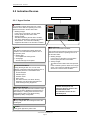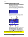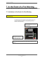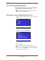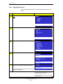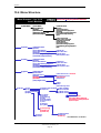
1
Release 3
System Program Version 3.8.0
Operator's Handbook
Fire Alarm Control Panel, BS-310 / 320 /
Operator Panel BS-330
Protecting life, environment and property...
ASAFE-FO/FE Rev. I, 2009-02-27
COPYRIGHT ©
This publication, or parts thereof, may not
be reproduced in any form, by any
method, for any purpose.
Autronica Fire and Security AS and its
subsidaries assume no reponsibility for
any errors that may appear in the
publication, or for damages arising from
the information in it. No information in this
publication should be regarded as a
warranty made by Autronica Fire and
Security. The information in this
publication may be updated without
notice.
Product names mentioned in this
publication may be trademarks. They are
used only for identification.
Table of Contents
Table of Contents
1. Introduction.......................................................................5
1.1
1.2
1.3
1.4
About the Handbook ......................................................................... 5
The Reader ....................................................................................... 5
Reference Documentation ................................................................ 5
Components ...................................................................................... 6
2. The Operator Panel - Overview........................................7
2.1
2.2
2.3
2.4
2.5
Introduction........................................................................................ 7
Indication Devices ............................................................................. 8
2.2.1 Upper Section ......................................................................... 8
2.2.2 The Operator Section (lower) ................................................. 9
The Menu Display ............................................................................. 10
Operating Buttons ............................................................................. 11
2.4.1 Overview ................................................................................. 11
2.4.2 Front Push Buttons ................................................................. 12
2.4.3 Alphanumeric Keyboard.......................................................... 12
2.4.4 Utility Buttons .......................................................................... 13
Internal Buzzer .................................................................................. 13
3. Operation Mode ................................................................14
3.1
3.2
3.3
3.4
3.5
3.6
3.7
3.8
3.9
3.10
3.11
3.12
3.13
3.14
3.15
3.16
Introduction........................................................................................ 14
Conditions in Operation Mode........................................................... 15
Alarm Levels...................................................................................... 15
Access Levels ................................................................................... 15
Configurable Alarm Presentations .................................................... 16
Alarm Presentation with Zonal and Point Indication (default) ........... 17
Alarm Presentation with Zonal Indication (optional) ......................... 18
How to View Point Information .......................................................... 19
How to View Detailed Zonal Information........................................... 20
Action Digits in Operation Mode........................................................ 21
Resounding the Internal Buzzer........................................................ 22
Resounding Fire Alarm Devices........................................................ 22
Resetting the System ........................................................................ 22
Alarm Disablement (AlarmDisable) ................................................... 23
Suppressed Information .................................................................... 23
Disablement Sources ........................................................................ 23
3.16.1 Overview ................................................................................. 23
3.16.2 Point Disablements ................................................................. 24
3.16.3 Other Unit Disablements......................................................... 24
3.17 Alarm Handling - A Typical Situation................................................. 25
3.18 Different Types of Detection Zones................................................... 26
3.18.1 Introduction ............................................................................. 26
3.18.2 Immediate Action Detection Zones......................................... 26
3.18.3 Coincidence Action Detection Zones...................................... 27
3.18.4 Delayed Action Detection Zones ............................................ 28
Operator's Handbook, AutroSafe Interactive Fire Alarm System, Release 3, ASAFE-FO/FE Rev. I, 2009-02-27,
Autronica Fire and Security AS
Page 1
Table of Contents
3.18.5 Delayed Coincidence Detection Zones................................... 30
3.18.6 Solas Detection Zones............................................................ 31
4. About «In the Event of….» ...............................................32
5. In the Event of a Fire Alarm .............................................34
5.1
5.2
6.
In the Event of a Fire Alarm - with Alarm Delay ...........38
6.1
6.2
7.
Indications in the Event of a Fire Alarm ............................................ 34
Actions to be Taken in the Event of a Fire Alarm.............................. 35
Indications - Fire Alarm with Alarm Delay ......................................... 38
Actions to be Taken - Fire Alarm with Alarm Delay .......................... 39
In the Event of a Fire Warning .........................................42
7.1
7.2
Indications in the Event of a Fire Warning ........................................ 42
Actions to be Taken in the Event of a Fire Warning.......................... 43
8. In the Event of Faults .......................................................45
8.1
8.2
Indications in the Event of Faults ...................................................... 45
Actions to be Taken in the Event of Faults ....................................... 46
9. Menu Mode ........................................................................48
9.1
9.2
9.3
9.4
9.5
9.6
How to Enter Menu Mode ................................................................. 48
The Menu Mode Display ................................................................... 48
Buttons Used to Operate the Menu................................................... 49
Action Digits in Menu Mode .............................................................. 49
9.4.1 Introduction ............................................................................. 49
9.4.2 Action Digits Table .................................................................. 49
How to Operate in Menu Mode ......................................................... 50
Example - How to Disable Detection Zones ..................................... 50
9.6.1 Using the Keyboard to Enter Text into the Input Field............ 51
9.6.2 Using the Up/Down Arrows in the Selection Field .................. 52
10. Show Status ......................................................................54
10.1
10.2
10.3
10.4
10.5
10.6
10.7
10.8
Introduction........................................................................................ 54
Show Status Menu ............................................................................ 54
Show Status - Fire Alarms ................................................................ 55
Show Status – Fire Warnings............................................................ 56
Show Status - Faults ......................................................................... 57
Show Status - Disablements ............................................................. 58
Show Status - Detection Zones in Test............................................. 60
Show Status – Activated Outputs...................................................... 61
11. Disabling............................................................................63
11.1
11.2
11.3
11.4
General.............................................................................................. 63
Disable Menu .................................................................................... 63
Indications on the Operator Panel..................................................... 64
Disabling Activated / Deactivated Components ................................ 64
Operator's Handbook, AutroSafe Interactive Fire Alarm System, Release 3, ASAFE-FO/FE Rev. I, 2009-02-27,
Autronica Fire and Security AS
Page 2
Table of Contents
11.5
11.6
11.7
11.8
11.9
11.10
11.11
11.12
Disabling Detection Zones ................................................................ 64
Disabling Points................................................................................. 65
Disabling Fire Alarm Devices ............................................................ 65
Disabling Fire Alarm Routing Equipment .......................................... 65
Disabling Outputs .............................................................................. 65
Disabling Fault Warning Routing Equipment .................................... 66
Disabling Immediate Output Actioning .............................................. 66
How to Execute Commands from the Disable Menu ....................... 67
12. Enabling ............................................................................69
12.1
12.2
12.3
12.4
12.5
12.6
12.7
12.8
12.9
12.10
12.11
General.............................................................................................. 69
Enable Menu ..................................................................................... 69
Enabling Activated / Deactivated Components................................. 70
Enabling Detection Zones ................................................................. 70
Enabling Points ................................................................................. 70
Enabling Fire Alarm Devices............................................................. 70
Enabling Fire Alarm Routing Equipment........................................... 71
Enabling Outputs............................................................................... 71
Enabling Fault Warning Routing Equipment ..................................... 71
Enabling Immediate Output Actioning............................................... 71
How to Execute Commands from the Enable Menu ......................... 72
13. System Menu.....................................................................74
13.1
13.2
13.3
13.4
13.5
13.6
13.7
13.8
13.9
Introduction........................................................................................ 74
System Menu .................................................................................... 74
How to Set / Change Date and Time ................................................ 75
How to View Current Program Version ............................................. 76
How to Enter Access Level 3 / Set Password................................... 77
13.5.1 Introduction ............................................................................. 77
13.5.2 Enter Access Level 3 .............................................................. 78
13.5.3 Leave Access Level 3 ............................................................. 78
13.5.4 Set (or Change) Password ..................................................... 79
How to Feed Paper ........................................................................... 80
How to Change Language ................................................................ 81
How to Initialize the Fire Alarm System ............................................ 82
Day / Night Timers............................................................................. 83
13.9.1 Starting / Stopping Automatic Day / Night
Operation from the Control Panel ........................................... 83
13.9.2 Overriding Automatic Day / Night Operation from the
Control Panel .......................................................................... 84
14. Service Commands ..........................................................85
14.1 Introduction........................................................................................ 85
14.2 Service Menu .................................................................................... 85
14.3 Testing............................................................................................... 86
14.3.1 Testing Detection Zones ......................................................... 87
14.3.2 Testing Outputs....................................................................... 92
14.4 Event Recording – Log Menu............................................................ 100
14.4.1 Events ..................................................................................... 101
14.4.2 How to Use the Log Menu ...................................................... 102
14.4.3 Logging All Events .................................................................. 104
14.4.4 The Log Setup Menu .............................................................. 105
14.5 Loop Commands ............................................................................... 110
Operator's Handbook, AutroSafe Interactive Fire Alarm System, Release 3, ASAFE-FO/FE Rev. I, 2009-02-27,
Autronica Fire and Security AS
Page 3
Table of Contents
14.5.1 Clear Topology........................................................................ 110
14.5.2 Disable Loop ........................................................................... 111
14.5.3 Enable Loop ............................................................................ 112
14.6 Report................................................................................................ 113
14.6.1 SV-Fault .................................................................................. 113
14.6.2 Polluted ................................................................................... 115
15. Appendix ...........................................................................117
15.1 Terms and Abbreviations .................................................................. 117
15.2 Zonal Definitions................................................................................ 119
15.2.1 General ................................................................................... 119
15.2.2 Detection Zone........................................................................ 119
15.2.3 Alarm Zone.............................................................................. 120
15.2.4 Operation Zone ....................................................................... 120
15.2.5 Configuration Example............................................................ 121
15.3 Action Digits Table - Operation Mode ............................................... 122
15.4 Menu Structure.................................................................................. 124
16. Index
............................................................................125
17. Figure List .........................................................................126
18. Reader’s Comments .........................................................127
Operator's Handbook, AutroSafe Interactive Fire Alarm System, Release 3, ASAFE-FO/FE Rev. I, 2009-02-27,
Autronica Fire and Security AS
Page 4
Introduction
1. Introduction
1.1 About the Handbook
This handbook is intended to provide the information necessary to
operate the AutroSafe Interactive Fire Alarm System from the Fire
Alarm Control Panel, BS-310/320 or the Operator Panel, BS-330.
As the user interface and operation of both panels are identical, the
panel is referred to as the operator panel throughout this handbook.
1.2 The Reader
The handbook is intended to be used by personnel who are
responsible for operating the system. We assume the reader has the
necessary basic understanding of the system concept (refer to
System Specification), and the term zone including, Detection Zone,
Alarm Zone and Operation Zone (refer to Appendix).
The AutroSafe Interactive Fire Alarm System comprises various
components (see chapter 1.4). It is important that the reader gets
familiarized with these, plus the different terms and abbreviations. A
list containing the most commonly used terms and abbreviations is
included in Appendix.
1.3 Reference Documentation
In addition to this handbook, Autronica Fire and Security offers the
following handbooks:
Handbook
System Specification
Installation Handbook, Fire Alarm Control Panel (BS-310/320) / Controller (BC-320)
Installation Handbook, Operator Panel (BS-330)
Installation Handbook, Repeater Panel (BU-320) / Information Panel (BV-320)
Installation Handbook, Battery Cabinet (SY-310)
Commissioning Handbook
Operator's Handbook, Repeater Panel (BU-320)
Operator's Handbook, Information Panel (BV-320)
Shortform User Guide
Wall Chart
Menu Structure
User Guide, Loop Diagnostic Tool, AS-2000
User Guide, Loop Simulator Tool
User Guide, Power Calculator Sheet
Item Number
P-ASAFE/XE
P-ASAFE-FA/DE
P-ASAFE-OP/DE
P-ASAFE-RI/DE
P-ASAFE-BC/DE
P-ASAFE/EE
P-ASAFE-FB/FE
P-ASAFE-IN/FE
P-ASAFE-SH/LE
P-ASAFE-WE/LX
P-ASAFE/MX
P-ASAFE-AS/FE
P-ASAFE-LS/FE
P-ASAFE-PC/FE
Operator's Handbook, AutroSafe Interactive Fire Alarm System, Release 3, ASAFE-FO/FE Rev. I, 2009-02-27,
Autronica Fire and Security AS
Page 5
Introduction
1.4 Components
The AutroSafe Interactive Fire Alarm System comprises the following
components (EN-54) :
Component
Abbreviation
Point
-
Control and indicating
equipment
c.i.e.
Power Supply
-
Fire Alarm Devices
FAD
Fire Alarm Routing
Equipment
FARE
Control for Fire Protection
Equipment
FPE
Fault Warning Routing
Equipment
FWRE
Description
Ref.
Detector or manual call-point.
A/
D
Equipment supplying power to, as well as accepting
fault and alarm signals from detectors. Indicates an
alarm condition audibly and visibly, plus the
location.
B
The source of power for control and indicating
equipment and for items supplied with power from
such equipment.
L
Equipment used to give warning of fire, for
example, a sounder or visual indicator.
C
Equipment used to route an alarm signal from
control and indicating equipment to a Fire Alarm
Receiving Station.
E
An automatic device used to actuate measures of
fire protection after receiving a signal from control
and indicating equipment (for example, fire
extinguishers, ventilation controllers).
G
Equipment used to route a fault warning signal from
control and indicating equipment to a fault warning
receiving station.
J
Fire Alarm Receiving
Station
-
A centre from which the necessary fire protection
measures can be initiated at any time.
F
Fault Warning Receiving
Station
-
A centre from which the necessary corrective
measures can be initiated.
K
Automatic Fire Protection
Equipment
-
Fire control or fire fighting equipment, for example,
extinguishing installation.
H
C
B
Fire Alarm
Control
and
indicating
equipment
A
Fire
A
detectors
D
C Device
E
F
Fire Alarm
Routing Eq.
Points
Manual
D
call-points
J
Fire Receiving
Station
K
Fault Warning
Receiving
Station
Fault Warning
Routing Eq.
G
Control for
Automatic
Fire Protection Eq.
H
Automatic Fire
Protection Eq.
L
Power
Supply
Note:
The lines linking the various components on the illustration indicate information flows,
and not physical interconnections.
Item G and H and some other items may need to be provided with a seperate power supply.
Operator's Handbook, AutroSafe Interactive Fire Alarm System, Release 3, ASAFE-FO/FE Rev. I, 2009-02-27,
Autronica Fire and Security AS
Page 6
The Operator Panel - Overview
2. The Operator Panel - Overview
2.1 Introduction
Each operator panel is assigned to one Operation Zone (refer to
«Zonal Definitions» in Appendix). Relative to its own zone, an
operator panel is local, while it is remote to operation zones which are
not encompassed by the local zone. All events and actions occurring
in a particular operation zone must be handled from a local operator
panel.
The operator panel displays information on events occurring in all
operation zones. However, the type of events and the level of details
of the given information depends on which operation zone the
information is related to. Local panels will list all detection zones in fire
alarm state. Remote operator panels will list remote alarms only, and
function as «indication only» devices.
The operator panel consists of two main sections. The upper section,
and the lower section which is the Operator Part.
19:23
ALARM
AUTROSAFE
SelfVerify
Fault
Function Disabled
Mute Panel
Function Delayed
Fire Brig. Signalled
More Events
Silence Alarms
Reset
Power
Testing
Fire Brig. Disabled
Fire Brig. Fault
System Fault
Alarms Disabled
Alarms Fault
1
2
3
4
5
6
7
8
9
C
0
i
®
Figure 2-1: The Operator Panel
Operator's Handbook, AutroSafe Interactive Fire Alarm System, Release 3, ASAFE-FO/FE Rev. I, 2009-02-27,
Autronica Fire and Security AS
Page 7
The Operator Panel - Overview
2.2 Indication Devices
Text Display - See chapter 2.3.
2.2.1 Upper Section
ALARM
ALARM
The red alarm indicator shows that one or more
detection zones within the operating zone of the
Operator Panel are in the fire alarm state.
• Blinking red light:
In the event of a fire alarm. The Fire Alarm
Devices (FAD) are still in active state.
Fault
Function Disabled
Fire Brig. Signalled
All FADs activated by the fire alarm condition
have been deactivated by operating the Silence
Alarms button. The control and indicating
equipment still remain in the fire alarm condition.
More Events
Silence Alarms
Reset System
Power
More Events
Fault
In the event of more than one alarm.
The yellow Fault Warning indicator shows the
presence of a fault within the operation zone of
the operator panel.
The red More Events indicator shows that several
detection zones within an operating zone are in
the fire alarm state.
• Blinking light
• Blinking red light:
Unaccepted fault warnings exist.
In the event of a fire alarm. The Fire Alarm
Devices (FAD) are still in active state.
• Steady light
All fault warnings are accepted.
• Steady red light:
Function Disabled
Steady yellow light when one or more of the
following components within the operation zone of
the operator panel are in the disabled state:
•
•
•
•
•
Mute Panel
Function Delayed
• Steady red light:
The Silence Alarms button has been pressed.
All
FADs activated by the fire alarm are no longer
active. The control and indicating equipment
still remain in the fire alarm condition.
function delayed
individual points
detection zones
alarm zones
Fire Alarm Devices, Fire Alarm Routing
Equipment, Fire Protection Equipment and
Fault Warning Routing Equipment.
Function Delayed
Steady yellow light indicates that Immediate Output
Actioning has been disabled (manual operation in
Menu Mode), i.e. a delay period is active for Fire
Alarm Devices (FAD) or Fire Alarm Routing
Equipment (FARE). Configurable.
Note that there are several national
variants of this panel. The
Indication Devices shown in this
handbook deals with
the Indication Devices for the
standard panel.
Fire Brig. Signalled
Steady red light when the message is sent to the
Fire Brigade.
Power
Steady green light when power is ON.
Operator's Handbook, AutroSafe Interactive Fire Alarm System, Release 3, ASAFE-FO/FE Rev. I, 2009-02-27,
Autronica Fire and Security AS
Page 8
The Operator Panel - Overview
2.2.2 The Operator Section (lower)
Testing
Fire Brig. Disabled
Fire Brig. Fault
System Fault
Alarms Disabled
Alarms Fault
1
2
3
4
5
6
9
7
8
C
0
i
®
Testing
Steady yellow light when one or more detection zones within the operation zone of the operator
panel have been manually set to the test state.
Fire Brig. Disabled
Steady yellow light when the signal to Fire Alarm Routing Equipment (FARE)
has been disabled. The Function Disabled indicator has also a steady yellow light.
Fire Brig. Fault
Yellow light when a fault is detected on Fire Alarm Routing Equipment (FARE). The Fault indicator
will also have a yellow light. Blinking (not accepted) / Steady (accepted).
System Fault
Steady yellow light when a system fault within the operating zone of the operator panel is present.
Alarms Disabled
Steady yellow light when one or more Fire Alarm Devices are disabled. The Function Disabled
indicator has also a steady yellow light.
Alarms Fault
Yellow light when a fault is detected on one or more Fire Alarm Devices (FAD). The Fault indicator
will also have a yellow light. Blinking (not accepted) / Steady (accepted).
Operator's Handbook, AutroSafe Interactive Fire Alarm System, Release 3, ASAFE-FO/FE Rev. I, 2009-02-27,
Autronica Fire and Security AS
Page 9
The Operator Panel - Overview
2.3 The Menu Display
During Normal Operation, the back light in the menu display is always
on.
The menu display has 16 lines of 40 characters.
The display is divided into several display windows showing different
types of information.
Header
Time
SHOW STATUS
DISABLEMENTS
1 DETECTION ZONES
2 POINTS
3 FIRE ALARM DEVICES
4 FIRE ALARM ROUTING EQUIPMENT
5 OUTPUTS
6 FAULT WARNING ROUTING EQUIPMENT
7 IMMEDIATE OUTPUT ACTIONING
8 ALL
FIRE ALARM
5 CONFERENCE HALL, MAIN BUILDING
19.23
Menu path
information
Menu elements
Information
field
Last alarm
detected if in
alarm condition
Figure 2-2: The Menu Display
Operator's Handbook, AutroSafe Interactive Fire Alarm System, Release 3, ASAFE-FO/FE Rev. I, 2009-02-27,
Autronica Fire and Security AS
Page 10
The Operator Panel - Overview
2.4 Operating Buttons
2.4.1 Overview
Front Push Buttons
19:23
ALARM
Mute Panel
(black)
AUTROSAFE
SelfVerify
Fault
Function Disabled
Mute Panel
Silence Alarms
(red)
Function Delayed
Fire Brig. Signalled
Silence Alarms
Reset
Power
Testing
Fire Brig. Disabled
Fire Brig. Fault
System Fault
Alarms Disabled
Alarms Fault
More Events
1
2
3
4
5
6
7
8
9
C
0
i
Reset
(green)
Alphanumeric Keyboard
®
1
2
3
4
JKL
5
6
7
STU
8
9
C
0
ABC
More Events
DEF
MNO
VWX
GHI
PQR
YZ
v
Utility Buttons
More Events
(black)
i
Help
Menu
Figure 2-3: Operating Buttons
Operator's Handbook, AutroSafe Interactive Fire Alarm System, Release 3, ASAFE-FO/FE Rev. I, 2009-02-27,
Autronica Fire and Security AS
Page 11
Close
The Operator Panel - Overview
2.4.2 Front Push Buttons
Front Push Buttons
Button
Designation
Mute Panel
(black)
Silence Alarms
(red)
Reset
(green)
v
Access
Level
Used to mute the panel. Timeout.
1
Used to silence Fire Alarm Devices (FAD) and cause
blinking serial numbers and lamps to go steady.
Timeout.
2
Used to reset the system.
2
In addition, a lamp test can be performed by pressing
and holding the Reset button for at least 5 seconds.
The lamp test is performed in access level 1 (no use
of key).
More Events
(black)
Used to scroll downwards among events in currently
active window (scroll page by page). Possible only if
there are more alarms than possible to display in the
window.
2
2.4.3 Alphanumeric Keyboard
The alphanumeric keyboard includes the numbers 1 to 9, the letters A
to Z, plus the following buttons:
Alphanumeric Keyboard
Button
ENTER
Designation
Used to select/approve a selection (parameter) or return.
6
PQR
9
Up/down arrow
buttons
Used to scroll lines up and down in the display picture.
YZ
Cancel
Used to cancel the last alphameric character input (back space).
C
Operator's Handbook, AutroSafe Interactive Fire Alarm System, Release 3, ASAFE-FO/FE Rev. I, 2009-02-27,
Autronica Fire and Security AS
Page 12
The Operator Panel - Overview
2.4.4 Utility Buttons
Utility Buttons
Button
Designation
Help
The Help button allows you to get useful information quickly while
operating the system. You can look up information on how to
operate the panel. NOT YET IMPLEMENTED.
Menu
Used to switch between Operation Mode and Menu Mode.
i
Operation Mode (operate ) >> Menu Mode (operate or timeout) >> Operation Mode.
Close
Used to move back one level / show previous picture if the display is
not showing information on the top level.
2.5 Internal Buzzer
Each operator panel provides a buzzer which is activated as
described below. Each condition may have its own sound pattern. If
more than one condition is present simultaneously, the state of the
operator panel and the buzzer signal will be decided. The buzzer will
reflect the condition which has the highest priority.
The internal buzzer is controlled by hardware. It is activated in the
cases of:
• System Fault
• Alarm
• Prealarm
• Early Warning
The buzzer can be silenced by pressing the Mute Panel button. One
exception is the buzzer signal indicating System Fault which can not
be silenced.
If the reason for the buzzer signal still exists, the buzzer will resound
after a predefined time.
Operator's Handbook, AutroSafe Interactive Fire Alarm System, Release 3, ASAFE-FO/FE Rev. I, 2009-02-27,
Autronica Fire and Security AS
Page 13
Operation Mode
3. Operation Mode
3.1 Introduction
The operator panel can be in either Operation Mode or Menu Mode.
When no one is operating the panel and no button has been pressed,
the panel will always be in Operation Mode.
The display may look as follows in the panel’s idle state.
19:23
Total: 3
AUTROSAFE
SelfVerify
Figure 3-1: The idle display
Note that an alarm, a disablement, test or fault will always be
indicated on the display when such events occur.
NOTE:
All events that may occur are presented in Operation Mode.
All handling of events, i.e. Silence Alarms, Accept and
System Reset takes place in Operation Mode.
It is possible to enter Operation Mode in two different ways.
• initial mode (start up) - idle state
• when pressing the menu button in Menu Mode, which will leave
menu mode from all menu levels
Operator's Handbook, AutroSafe Interactive Fire Alarm System, Release 3, ASAFE-FO/FE Rev. I, 2009-02-27,
Autronica Fire and Security AS
Page 14
Operation Mode
3.2 Conditions in Operation Mode
In Operation Mode, the system can be in quiescent condition (lowest
priority), or the system can be in one or any combination of the
following conditions:
•
•
•
•
•
fire alarm condition (highest priority)
fire warning condition (including prealarm and early warning)
fault warning condition
disablement condition
test condition
3.3 Alarm Levels
A detector may signal different levels of alarm, indicating the amount
of smoke or gas currently present. These are;
• Fire Alarm Level (the highest level)
• Fire Warning, including:
- Prealarm Level
- Early Warning
Whenever a detector detects a transition from one alarm level to
another, this event is reported to the system as an Early Warning,
Prealarm or Fire Alarm signal, which in turn will initiate the appropriate
actions.
3.4 Access Levels
All user interface controls are classified as belonging to one of the
four different access levels described below:
Access
Level
Access Remedy
Description
1
No key or password
required.
Accessible by members of the general public. All mandatory
indications are visible at access level 1 without prior manual
intervention.
2
Access by key.
Accessible by persons having a specified responsibility for
safety.
3
Password restricted.
Accessible by persons trained and authorized to do
reconfiguration of site specific data and maintenance
according to the manufacturer’s published instruction.
4
Mechanical tool.
Accessible by persons doing repair work and changing
firmware.
Operator's Handbook, AutroSafe Interactive Fire Alarm System, Release 3, ASAFE-FO/FE Rev. I, 2009-02-27,
Autronica Fire and Security AS
Page 15
Operation Mode
3.5 Configurable Alarm Presentations
The alarm presentation is configurable. By default alarms are
presented with both zonal indication (detection zones) and point
indication. An option is zonal indication only, with the possibility to
view point information by operating a button (Action Digit 1: Show
Points).
Chapter 3.6 deals with the default presentation of alarms.
Chapter 3.7 and 3.8 deals with the optional alarm presentation (zonal
indication).
The optional alarm presentation with zonal indication is used
throughout the handbook.
The different events, for example, «In the Event of a Fire Alarm», are
presented in Operation Mode.
Operator's Handbook, AutroSafe Interactive Fire Alarm System, Release 3, ASAFE-FO/FE Rev. I, 2009-02-27,
Autronica Fire and Security AS
Page 16
Operation Mode
3.6 Alarm Presentation with Zonal and Point Indication
(default)
By default alarms are presented with both zonal indication and point
indication.
“FIRE ALARMS” is highlighted in the upper left corner of the display.
In the example below an optical smoke detector in the “Main building
Show room gr. floor” (1 zone) issues an alarm signal.
FIRE ALARMS
19:23
Total: 1
1 Main building Show room gr. floor
A1021 Smoke
Latest zone in alarm
Main building Show room gr. floor
Zones: 1
A manual call point in the reception area is activated. A total of 2
alarms from 2 different zones are now shown in the display.
FIRE ALARMS
19:24
Total: 2
1 Main building Show room gr. floor
A1021 Smoke
2 Main building Reception area
A1019 Manual callpoint
Latest zone in alarm
Main building Reception area
Zones: 2
The heat detector in the “Main building Show room gr. floor” issues an
alarm signal. A total of 3 alarms from 2 zones are shown in the
display.
FIRE ALARMS
19:24
Total: 3
1 Main building Show room gr. floor
A1021 Smoke
2 Main building Reception area
A1019 Manual callpoint
3 Main building Show room gr. floor
A1020 Heat
Latest zone in alarm
Main building Show room gr. floor
Zones: 2
Operator's Handbook, AutroSafe Interactive Fire Alarm System, Release 3, ASAFE-FO/FE Rev. I, 2009-02-27,
Autronica Fire and Security AS
Page 17
Operation Mode
3.7 Alarm Presentation with Zonal Indication (optional)
Note that the optional alarm presentation with zonal indication is
used throughout the handbook.
FIRE ALARMS, for example, is shown highlighted in the upper left
corner of the display.
The example below shows a situation where three zones are in alarm
state. The total number of zones in alarm is shown in the upper right
corner.
Zones in alarm
FIRE ALARMS
Total number
of zones in alarm
19:23
Total: 3
1 OFFICES
2 CANTEEN
3 WORKSHOP
Operator's Handbook, AutroSafe Interactive Fire Alarm System, Release 3, ASAFE-FO/FE Rev. I, 2009-02-27,
Autronica Fire and Security AS
Page 18
Operation Mode
3.8 How to View Point Information
Note that the optional alarm presentation with zonal indication is
used throughout the handbook. The default alarm presentation
provides both zonal and point information.
To be able to select among detection zones in alarm, for example, «In
the Event of a Fire Alarm», you simply press the ENTER button ( ).
You can now use the up/down arrow buttons to select the wanted
zone.
19:23
19:23
Total: 33
Total:
FIRE ALARMS
1 OFFICES
2 CANTEEN
3 WORKSHOP
1: SHOW POINTS
To view points in alarm for the zone you have selected (highlighted),
you simply press digit 1 (SHOW POINTS, see Action Digits, 3.10),
and the following screen picture will appear (example):
The exact time
when the alarm
was received
The point(s)
in alarm
The point
type
19:23
Total: 3
SHOW STATUS
FIRE ALARMS/POINTS
1 OFFICES
Received 19:29:44
POINT:
P3
P5
TYPE:
Heat
Optical
STATUS:
Alarm
Alarm
FIRE ALARMS
3 WORKSHOP
Total: 3
Total number
of zones in alarm
Last zone
in alarm
Here (in this example) you can view the points in alarm and the type
of point (detector type, manual call point). The arrow buttons are used
to move up and down in the list of points.
The close button (
) is used to go one step backwards (at any time).
NOTE: If you have entered SHOW STATUS for information on points in alarm, you have
to press the Close button to re-enter Operation Mode in order to activate the Silence
Alarms button and the Reset button.
Operator's Handbook, AutroSafe Interactive Fire Alarm System, Release 3, ASAFE-FO/FE Rev. I, 2009-02-27,
Autronica Fire and Security AS
Page 19
Operation Mode
3.9 How to View Detailed Zonal Information
Note that the optional alarm presentation with zonal indication is
used throughout the handbook. The default alarm presentation
provides both zonal and point information.
To be able to select among zones in alarm, fault or test state, you
simply press the ENTER button ( ). You can now use the up/down
arrow buttons to select the wanted zone (in this example Fire Alarms).
19:23
19:23
Total: 33
Total:
FIRE ALARMS
1 OFFICES
2 CANTEEN
3 WORKSHOP
1: SHOW POINTS
To view detailed zonal information for the zone you have selected
(highlighted), you simply press the ENTER button ( ) once more. ,
The following screen picture will appear (example):
The time
entering
alarm
Zone in
Alarm
Outputs
activated
(or not)
The point
type
First
point
19:23
Total: 3
FIRE ALARM INFO
ZONE IN ALARM
OFFICES
FIRST POINT/MCP IN FIRE ALARM:
P6
Manual
TIME ENTERING ALARM: 19:07
OUTPUTS
ACTIVATED BY
ACTIVATION TIME
1: SHOW POINTS
: Activated
: McpOperation
: 19:07
FIRE ALARMS
3 WORKSHOP
Last
zone
in alarm
Total: 3
Activated
by
The
activation
time
Total
number
of zones
in alarm
Detailed zonal information will be available. In the example above you
can view the zone in alarm, the first point in fire alarm, the time
entering alarm, the activation state of outputs, what triggered the
alarm (for example, Manual Call-point operation) and the activation
time. You can also move directly to SHOW POINTS (press digit 1).
The close button (
) is used to go one step backwards (at any time).
NOTE: If you have entered SHOW STATUS for more detailed point information, you
have to press the Close button to re-enter Operation Mode in order to activate the
Silence Alarms button and the Reset button.
Operator's Handbook, AutroSafe Interactive Fire Alarm System, Release 3, ASAFE-FO/FE Rev. I, 2009-02-27,
Autronica Fire and Security AS
Page 20
Operation Mode
3.10 Action Digits in Operation Mode
When operating in Operation Mode, special Action Digits will appear
in the highlighted field (Information Field) at the lower part of the
display. These digits show at any time which action the operator may
perform.
Digits 1 to 4 on the alphanumeric keyboard are dedicated for
the different actions (Action Digits). The type of action
depends on the current state of the system.
1
ABC
3
2
GHI
DEF
4
JKL
Figure 3-5: Action Digits in Operation Mode
For example, digit 1 in the event of a fire alarm (after silencing alarms)
represents RESOUND.
The example below shows a situation where Action Digit 4 (SHOW
SUPPR. INFO = suppressed information) is available.
19:23
Total: 3
FIRE ALARMS
1 OFFICES
2 WORKSHOP
3 CANTEEN
4: SHOW SUPPR. INFO
Action Digit
Figure 3-6: Action Digits shown in the Information Field
In Appendix you will find a table providing a complete list of all Action
Digits that may appear in Operation Mode.
Operator's Handbook, AutroSafe Interactive Fire Alarm System, Release 3, ASAFE-FO/FE Rev. I, 2009-02-27,
Autronica Fire and Security AS
Page 21
Operation Mode
3.11 Resounding the Internal Buzzer
After pressing the MUTE PANEL button in an alarm condition, the
internal buzzer will automatically be resounded in the following cases:
• if any new event occurs (for example, a detection zone enters the
Fire Alarm state)
• after a timeout period if the cause for making it sound is still
present.
3.12 Resounding Fire Alarm Devices
When pressing the SILENCE ALARMS button in the event of an
alarm, all fire alarm devices (FAD) within the operation zone of the
operator panel will be deactivated. The red Fire Alarm indication lamp
will switch from blinking to steady light.
At this stage, the resound timer will start. The resound timer will
restart on each operation of the SILENCE ALARMS button.
To manually resound the alarm zones, Action Digit 1, which
represents RESOUND, can be pressed.
The alarm zones are automatically resounded to their alarm states on
timeout (configurable) of the SILENCE resound timer.
3.13 Resetting the System
In order to reset the system by pressing the RESET button, all Fire
Alarm Devices (FAD) have to be silenced / deactivated using the
SILENCE ALARMS button. Otherwise the reset operation will be
rejected without having any effect on system behaviour (configurable).
Operator's Handbook, AutroSafe Interactive Fire Alarm System, Release 3, ASAFE-FO/FE Rev. I, 2009-02-27,
Autronica Fire and Security AS
Page 22
Operation Mode
3.14 Alarm Disablement (AlarmDisable)
If there are points within an operation zone still signalling a Fire Alarm,
an alarm disablement will take effect.
Alarmdisabling may or may not be required to be confirmed by the
operator (configurable).
• If confirmation is not required, all points still signalling a Fire Alarm,
are automatically disabled.
• If confirmation is required, a list of points in alarm is presented on
the display. To confirm automatic disablement, the ENTER button
( ) must be pressed within 5 seconds (configurable).
All alarmdisabled detectors can be enabled at this stage by pressing
Action Digit 3, which represents REACTIVATE .
3.15 Suppressed Information
When operating in Operation Mode, the message SHOW SUPPR.
INFO may appear in the highlighted field at the lower part of the
display. This indicates that there are conditions that are active, but
suppressed, i.e. not shown on the display.
To reveal suppressed information, Action Digit 4, representing SHOW
SUPPRESSED INFO, can be pressed.
3.16 Disablement Sources
3.16.1 Overview
The AutroSafe Interactive Fire Alarm System supports the following
disablement sources:
• Individual
A unit is disabled by an individual command issued to the specified
unit. Applicable to all units with disable capability.
• Loop
A unit is dsabled by its corresponding loop being disabled.
Applicable to Points, FADs, FPEs and panels connected to loops
(DID, remote silence / reset).
• Zone
A point is disabled by a command to its corresponding detection
zone, affecting all Points in the detection zone, including any
manual call points. Applicable to Points only.
• Disable Input Unit
A point is disabled by a command from a Disablement Input Unit
via its corresponding detection zone. Applicable to Points only.
• Master Zone
equivalent with Zone, except from that the command is issued to
AutroSafe over the AutroCom connection. Applicable to Points
only.
Operator's Handbook, AutroSafe Interactive Fire Alarm System, Release 3, ASAFE-FO/FE Rev. I, 2009-02-27,
Autronica Fire and Security AS
Page 23
Operation Mode
3.16.2 Point Disablements
A general rule is that a Point may be disabled by one or more
disablement sources simultaneously. To be enabled, the Point must
be enabled from all these disablement sources.
Example:
A Point is disabled from a Zone (Detection Zone disable command
issued from an Operator Panel) and from a Disable Input Unit. For the
Point to become enabled, a DZ enable command must be issued from
the Operator Panel and the Restore button on the Disable Input Unit
must be pressed.
Exceptions to this general rule is as follows:
• Individual enablements will override and remove all other
disablements but Loop disablements. The reason for this is that an
individual Point disablement should be regarded as a sort of
service command used in exceptional circumstances, disabling of
Points is usually done via its Detection Zone.
• Master Zone enablements will override and remove all Master
Zone, Zone and Disablement Input Unit disablements.
3.16.3 Other Unit Disablements
Other units (than Points) are only affected by Individual and Loop
disablements.
Note that in contrast to Point disablements, there is no memory in the
system in conjunction with Loop disable / enable operations: When a
loop is disabled and then enabled, any disablements which may have
existed before the loop disable will be lost. In other words, all loop
units (except Points which have this memory function, see above) will
be enabled when enabling the corresponding loop.
Operator's Handbook, AutroSafe Interactive Fire Alarm System, Release 3, ASAFE-FO/FE Rev. I, 2009-02-27,
Autronica Fire and Security AS
Page 24
Operation Mode
3.17 Alarm Handling - A Typical Situation
The handling of a fire situation will typically contain the following
phases:
• One or more detection zones are issuing Prealarm signals
(Accept).
• One or more of these detection zones will go into Fire Alarm,
activating Fire Alarm Devices (FAD) and Fire Protection Equipment
(FPE).
• When the operator has investigated the cause of the alarm, the
activated Fire Alarm Devices (FAD) may be deactivated when the
situation is under control (Silence Alarms).
• If the deactivation of the Fire Alarm Devices (FAD) shows to be
erroneous, the Fire Alarm Devices (FAD) may be resounded
(Resound).
• After silencing the Fire Alarm Devices (FAD), the system may be
reset. Reset will delete all indications of the fire situation and, if
physically possible, deactivate the Fire Protection Equipment
(FPE) (Reset).
• The reset operation includes alarm disabling of all those points
within the operation zone of the operating panel still signalling Fire
Alarm (must be confirmed by the operator). Alarmdisabling may
later be cancelled and the points made to retransmit their alarm
level (Reactivate).
Operator's Handbook, AutroSafe Interactive Fire Alarm System, Release 3, ASAFE-FO/FE Rev. I, 2009-02-27,
Autronica Fire and Security AS
Page 25
Operation Mode
3.18 Different Types of Detection Zones
3.18.1 Introduction
When handling events in Operation Mode, it is important to be aware
of differences regarding the detection zone configuration (configured
by using the AutroSafe Configuration Tool).
The type of the specific detection zone as well as the type of point
(detector or manual call point) will determine how the system
responds to the signal - with respect to action.
The system has the following types of detection zones:
• Immediate Action detection zone
• Coincidence Action detection zone
• Delayed Action detection zone
• Delayed Coincidence detection zone
• SOLAS (Safety of Life at Sea) detection zone
3.18.2 Immediate Action Detection Zones
A signal from an Immediate Action detection zone, will initiate all
actions immediately, without any delay.
Immediate Action applies to:
• Fire Alarm Devices (FAD)
• Fire Alarm Routing Equipment (FARE)
• Fire Protection Equipment (FPE)
Operator's Handbook, AutroSafe Interactive Fire Alarm System, Release 3, ASAFE-FO/FE Rev. I, 2009-02-27,
Autronica Fire and Security AS
Page 26
Operation Mode
3.18.3 Coincidence Action Detection Zones
A fire alarm signal from a single detector in a Coincidence Action
detection zone, will initiate no actions, i.e. there will be no actioning of
outputs to;
• Fire Alarm Devices (FAD)
• Fire Alarm Routing Equipment (FARE)
• Fire Protection Equipment (FPE)
- provided that FAD, FARE and FPE are set to Qualified Action (see
next page)
At least two detectors in the same detection zone must be in
alarm state before actions are initiated.
Note that an activation of a manual call-point in a coincidence
action detection zone will always initiate actions.
In the display, the alarm number for a detection zone will remain
steady until a new point in the same zone enters alarm state.
Note that the optional alarm presentation with zonal indication is
used throughout the handbook.
In the example below, the detection zone 2 CANTEEN is configured
as a zone with coincidence action.
Steady number (2) if only one detector
in this zone is in alarm state.
FIRE ALARMS
19:23
Total: 3
1 OFFICES
2 CANTEEN
3 WORKSHOP
Blinking number (2) if two or several
points or one manual call point in the
same zone are in alarm state.
FIRE ALARMS
19:23
Total: 3
1 OFFICES
2 CANTEEN
3 WORKSHOP
Figure 3-7: Coincidence Action detection zone - indication
Operator's Handbook, AutroSafe Interactive Fire Alarm System, Release 3, ASAFE-FO/FE Rev. I, 2009-02-27,
Autronica Fire and Security AS
Page 27
Operation Mode
3.18.4 Delayed Action Detection Zones
When the operator panel receives a fire alarm signal from a point in a
Delayed Action detection zone (configurable), the actioning of outputs
to Fire Alarm Devices (FAD) and/or Fire Alarm Routing Equipment
(FARE) can be delayed.
In an alarm situation, the actioning of outputs will be delayed when;
• the detection zone has been defined as a Delayed Action detection
zone (configurable)
• the point(s) in this Delayed Action detection zone has been set to
point delay ON (the default configuration)
• Immediate Output Actioning has been disabled (in the Disable
menu, refer to How to Disable Immediate Output Actioning, page
66).
• the actual FAD / FARE has been set to Qualified Action
(configurable)
Note that activation of a manual call-point will normally (point
delay OFF) give immediate output actioning even though the
immediate output actioning has been disabled (configurable).
The operation of delays to outputs to Fire Alarm Devices (FAD) and
Fire Alarm Routing Equipment apply to:
• detectors and/or
• manual call-points and/or
• signals from specific zones
The delay is divided into two delay periods, Initial delay, T1
(configurable) and Prolonged Delay, T2 (configurable).
The (T1) delay period is started when a Fire Alarm signal from a point
is received. Actions will be initiated after the T1 delay period has
expired. Pressing Action Digit 4, which represents PROLONG DELAY,
will terminate T1 and the delay period T2 will start.
If one or more Delayed Action detection zones have entered the Fire
Alarm state and are in their T1 or T2 periods, the delayed actions can
be immediately initiated by pressing Action digit 2, which represents
ACTIVATE. Activation of a manual call point with the Operation Zone
will also give immediate action.
Operator's Handbook, AutroSafe Interactive Fire Alarm System, Release 3, ASAFE-FO/FE Rev. I, 2009-02-27,
Autronica Fire and Security AS
Page 28
Operation Mode
In the display, a detection zone with its outputs delayed is indicated by
a @ in front of the zone text. The time for the first delayed action is
also displayed.
Note that the optional alarm presentation with zonal indication is
used throughout the handbook.
Delayed Action Indication (@)
19:23
Total: 3
FIRE ALARMS
1 OFFICES
2 CANTEEN
3 @ WORKSHOP
FIRST DELAYED OUTPUTS ACTIVATES 19:40
2: ACTIVATE
4: SHOW SUPPR. INFO
After pressing the ENTER button ( ) and selecting the delayed
action zone, you can;
• press Action Digit 1 to show the points in alarm
• press Action Digit 2 to activate the alarm
or
press Action Digit 4 to prolong the delay.
19:23
Total: 3
FIRE ALARMS
1 OFFICES
2 CANTEEN
3 @ WORKSHOP
DELAYED OUTPUTS ACTIVATES 19:40
1: SHOW POINTS
2: ACTIVATE
4: PROLONG DELAY
Action Digits
Figure 3-8: Delayed Action detection zone - indication
Operator's Handbook, AutroSafe Interactive Fire Alarm System, Release 3, ASAFE-FO/FE Rev. I, 2009-02-27,
Autronica Fire and Security AS
Page 29
Operation Mode
3.18.5 Delayed Coincidence Detection Zones
Detection zones configured as Delayed Coincidence Detection Zones
have the following properties:
In Day Mode (Immediate Output Actioning is disabled), outputs that
are configured to be activated by these detection zones will operate
according to their actual configuration, i.e. Silent Alarm, Small Alarm
or Large Alarm as follows:
When a fire alarm signal from the first detector in alarm is received,
the following will occur:
1. The detection zone will enter the Silent Alarm state, and all
FPE outputs configured to be activated on Silent Alarm will be
activated. The (T1) delay period will start.
2. When the T1 delay period expires, the detection zone will
enter the Small Alarm state. All FPE outputs configured to be
activated on Small Alarm will be activated. The (T2) delay
period will start.
3. When the T2 delay period expires, the detection zone will
enter the Large Alarm state. All FPE outputs configured to be
activated on Large Alarm will operate.
Note that, at any time, if an alarm from a second detector within the
same detection zone is received, the detection zone will always enter
the Large Alarm State. This will mean that all (not yet activated) FPE's
configured to be activated on Silent, Small and Large Alarm will be
activated.
Pressing the reset button during a delay period will terminate the
delay period (T1 or T2).
In Night Mode (Immediate Output Actioning is enabled), outputs are
always activated on the first detector in alarm and the system will
always enter the Large Alarm state. As with Day Mode this will mean
that all (not yet activated) FPE's configured to be activated on Silent,
Small and Large Alarm will operate.
Note that when a manual call-point (point delay OFF) is
activated, or when a Heat Detector (point delay OFF) sends an
alarm signal, a Delayed Coincidence detection zone will always
enter the Large Alarm state directly, regardless of Day or Night
Mode.
In an alarm situation, the actioning of outputs will behave as described
above, provided that;
• the detection zone has been defined as a Delayed Coincidence
detection zone (configurable)
and
• the point(s) in this Delayed Action detection zone has been set to
point delay ON (the default configuration)
Operator's Handbook, AutroSafe Interactive Fire Alarm System, Release 3, ASAFE-FO/FE Rev. I, 2009-02-27,
Autronica Fire and Security AS
Page 30
Operation Mode
3.18.6 Solas Detection Zones
When the operator panel receives a fire alarm signal from a point in a
SOLAS - Safety of Life at Sea - detection zone (configurable), all
actions will be initiated after a programmed delay has expired.
The (T1) delay period is started when a signal from a point is
received. Pressing Action digit 4, which represents BLOCK ALARM,
will terminate the delay period and block the alarm for an indefinite
period of time.
SOLAS applies to fire Alarm Devices (FAD), Fire Alarm Routing
Equipment (FARE) - detectors only, and Fire Protection Equipment
(FPE) - option.
Operator's Handbook, AutroSafe Interactive Fire Alarm System, Release 3, ASAFE-FO/FE Rev. I, 2009-02-27,
Autronica Fire and Security AS
Page 31
About «In the Event of….»
4. About «In the Event of….»
The subsequent chapters - In the event of…..- deal with different
events that may occur;
Chapter
In the event of…..
Chapter 5
a fire alarm
Chapter 6
a fire alarm with alarm delay (in a Delayed Action detection
zone - immediate output actioning disabled)
Chapter 7
a fire warning (prewarning/early warning)
Chapter 8
faults
The list above covers the most common events. In addition to these, a
great number of combinations of events may, of course, occur.
The operational information included in chapter 3, plus the overview of
buttons and indicators in chapter 2, are intended to provide the
information necessary to successfully operate the AutroSafe
Interactive Fire Alarm System. As additional help, messages in the
Information Field will tell you at any time what options you have.
Note that the optional alarm presentation with zonal indication is
used throughout the handbook.
For each event there is an overview of all indications on the panel,
plus the necessary actions to take. All alarm handling and display
pictures shown in the subsequent chapters are based on the
following:
• The system is in Operation Mode.
• To operate the panel, Access Level 2 is required. This means that
the person who operates the panel, must use a key before the
panel can be operated. This is indicated with a key.
• The examples show a system that is configured to immediately
trigger Fire Alarm Routing Equipment and send a message to a
Fire Receiving Station (Fire Brigade) in the event of a fire alarm.
The Fire Brig. Signalled indicator will thus come on.
• As you proceed through the steps in the different events, the
comments field will, when necessary, provide additional
information and show the different options you have.
• In many cases, several display pictures will be shown when a
command has been executed. These quick changes from one
display picture to another are indicated with an arrow.
• The table for the different procedures is divided into four columns
with the following headings;
Step
Actions to be taken
Display Indication
Audible Indication
Operator's Handbook, AutroSafe Interactive Fire Alarm System, Release 3, ASAFE-FO/FE Rev. I, 2009-02-27,
Autronica Fire and Security AS
Page 32
About «In the Event of….»
(This page is left blank intentionally)
Operator's Handbook, AutroSafe Interactive Fire Alarm System, Release 3, ASAFE-FO/FE Rev. I, 2009-02-27,
Autronica Fire and Security AS
Page 33
In the Event of a Fire Alarm
5. In the Event of a Fire Alarm
Note that the optional alarm presentation with zonal indication is used throughout the handbook.
5.1 Indications in the Event of a Fire Alarm
One or several fire detectors or manual call points in one or several detection zones are
signalling a Fire Alarm.
The following shows the indications on the Operator Panel in the
event of «Fire Alarm» within the operation zone of the panel.
The text display indicates the detection zones in alarm state and their
location. In addition, the following information is shown by operating the
menu:
- detailed zonal information
- information on the specific points in alarm
The red Alarm indicator is
blinking.
ALARM
Fault
The Fire Brig. Signalled
indicator has a steady red
light.
Function Disabled
Fire Brig. Signalled
Power
Testing
Fire Brig. Disabled
Fire Brig. Fault
System Fault
Alarms Disabled
The internal buzzer is
activated.
Mute Panel
Function Delayed
Alarms Fault
More Events
Silence Alarms
Reset System
1
2
3
4
5
6
9
7
8
C
0
i
Default pattern on the
sound:
1 sec. ON, 1 sec. OFF
®
Activated functions:
A message is sent to the Fire Brigade.
The fire alarm condition activates Fire Alarm Devices (sounders and
visual indicators).
Operator's Handbook, AutroSafe Interactive Fire Alarm System, Release 3, ASAFE-FO/FE Rev. I, 2009-02-27,
Autronica Fire and Security AS
Page 34
In the Event of a Fire Alarm
5.2 Actions to be Taken in the Event of a Fire Alarm
Step
Actions to be taken
1
Follow all precautions
described in the local
fire instructions, step by
step.
Display Indication
FIRE ALARMS
Audible Indication
19:23
Total: 3
1 OFFICES
2 CANTEEN
3 WORKSHOP
All fire alarm devices
connected to the
alarm zones (which
are connected to the
detection zones in
alarm) are activated
(sounders and visual
indicators).
The internal buzzer on
the operator panel is
turned on.
Comments:
2
3
To silence the internal
buzzer, press the black
Mute Panel button
Press
and observe
the zone(s) in alarm
state in the display.
Comments:
The red FIRE indicator starts to blink.
The red Fire Brig. Signalled indicator is lit.
When several zones are in alarm state, the More Events indicator is lit.
FIRE ALARMS
19:23
Total: 3
FIRE ALARMS
19:23
Total: 3
1 OFFICES
2 CANTEEN
3 WORKSHOP
The internal buzzer on
the operator panel is
turned off.
1 OFFICES
2 CANTEEN
3 WORKSHOP
The first detection zone will be highlighted instead of the heading FIRE
ALARMS.
In this example, a total of 3 zones are in alarm state. If you want to view
detailed zonal/point information for each of the zones before investigating the
scene(s), go to step 5. If not, investigate the scene(s), then go directly to step
9.
If the message «SHOW SUPPR. INFO» is shown in the lower right corner,
one or several fire warnings, disablements, tests or faults exist. To view
suppressed information, press Action Digit 4 (SHOW SUPPR. INFO).
4
Investigate the scene(s)
and carry out the
necessary actions.
FIRE ALARMS
5
To select a zone, scroll
with the arrow buttons
FIRE ALARMS
6
PQR
or
9
19:23
Total: 3
1 OFFICES
2 CANTEEN
3 WORKSHOP
19:23
Total: 3
1 OFFICES
2 CANTEEN
3 WORKSHOP
YZ
6
To view detailed zonal
information, press
7
To view points in alarm,
press Action Digit 1
(SHOW POINTS).
8
To go two steps
backwards, press
twice.
Comments:
FIRE ALARMS
19:23
Total: 3
1 OFFICES
2 CANTEEN
3 WORKSHOP
If you want to view detailed information for another zone, select the other
zone in step 5, repeat step 6, 7 and 8, then go to step 9. If not, go directly to
step 9.
Operator's Handbook, AutroSafe Interactive Fire Alarm System, Release 3, ASAFE-FO/FE Rev. I, 2009-02-27,
Autronica Fire and Security AS
Page 35
In the Event of a Fire Alarm
Step
9
Actions to be taken
To silence all alarms,
press the red Silence
Alarms button.
Display Indication
SILENCE
Info
Audible Indication
19:23
All Fire Alarm Devices
(FAD) are deactivated.
: Completed
FIRE ALARMS
3 WORKSHOP
Total: 3
FIRE ALARMS
19:23
Total: 3
1 OFFICES
2 CANTEEN
3 WORKSHOP
1: RESOUND
Comments:
The red FIRE indicator goes steady.
To manually resound the alarm zones at this stage, Action Digit 1
(RESOUND) can be pressed.
The alarm zones are automatically resounded to their alarm states on
timeout of the silence resound timer.
When the fire is extinguished and all necessary repair work is implemented
(smoke is exhausted, new glass replaced in the manual call-points, etc.), the
system should be returned to normal operating mode.
The SILENCE ALARMS button has to be pressed before pressing the
RESET button. Otherwise the reset operation will be rejected without having
any effect on system behaviour.
10
Press the green Reset
button.
RESET
Info
Comments:
19:23
All audible indicators
on all panels within the
operation zone of the
operator panel are
turned off.
: Completed
If there are no points signalling a fire alarm, the system is reset.
The red FIRE indicator goes off.
The red Fire Brig. Signalled indicator goes off.
The panel enters its idle state.
AUTROSAFE
SelfVerify
If there are points still
signalling an alarm when the
system is reset, go to the next
page.
Operator's Handbook, AutroSafe Interactive Fire Alarm System, Release 3, ASAFE-FO/FE Rev. I, 2009-02-27,
Autronica Fire and Security AS
Page 36
In the Event of a Fire Alarm
Step
Actions to be taken
The point(s) still in alarm will be
shown on the display.
If no actions are taken, the
points still signalling alarm will
automatically be reactivated after
a predefined timeout.
If you want to disable the
point(s) - for example, a manual
call-point -still signalling alarm,
go to step 11. The points can
also be reactivated (step 12) at
any time after the disablement
(ALARMDISABLE) has taken
place.
11
To disable all points still
signalling alarm, press
Display Indication
Audible Indication
RESET
19:23
POINTS IN ALARM
19:23
P6
Press ‘ENTER’ to disable all points.
ALARM DISABLE
19:23
RESET
19:23
DISABLEMENT
DISABLED POINTS
1 P6
19:23
Total: 1
Total: 1
3: REACTIVATE
Comments:
The red Fire Brig. Signalled indicator goes off.
The yellow Function Disabled indicator is lit.
All point(s) still signalling alarm are disabled. To reactivate the point(s), you
have to press Action Digit 3 (REACTIVATE).
12
To reactivate the
point(s), press Action
Digit 3.
FIRE ALARMS
1 OFFICES
2 CANTEEN
3 WORKSHOP
REACTIVATE
Comments:
13
To reset the system,
repeat step 9 and 10.
(Press the red Silence
Alarms button and the
green Reset button).
Comments:
19:23
Total: 3
19:23
The point(s) will again
signal alarm.
The internal buzzer on
the operator panel is
turned on.
The yellow Function Disabled indicator goes off.
The red FIRE indicator starts to blink.
The red Fire Brig. Signalled indicator is lit.
SILENCE
19:23
RESET
19:23
If there are no points signalling a fire alarm, the system is reset.
The red FIRE indicator goes off.
The red Fire Brig. Signalled indicator goes off.
The panel enters its idle state.
AUTROSAFE
SelfVerify
Operator's Handbook, AutroSafe Interactive Fire Alarm System, Release 3, ASAFE-FO/FE Rev. I, 2009-02-27,
Autronica Fire and Security AS
Page 37
In the Event of a Fire Alarm with Alarm Delay
6. In the Event of a Fire Alarm with Alarm Delay
Note that the optional alarm presentation with zonal indication is used throughout the handbook.
6.1 Indications - Fire Alarm with Alarm Delay
A point set to Delayed Action (configurable) is sending an alarm signal from a Delayed Action
detection zone in a situation where Immediate Output Actioning has been disabled, i.e. the alarm
delay has been activated.
NOTE:
An alarm from a manual call-point is normally configured to give immediate actioning on the
alarm outputs even though Immediate Output Actioning has been disabled.
The following shows the indications on the Operator Panel in the
event of «Fire Alarm with Alarm Delay» within the operation zone of
the panel.
The text display indicates the detection zones in alarm state and their
location. In addition, the following information is shown by operating the
menu:
- detailed zonal information
- information on the specific points in alarm
The red Alarm indicator is
blinking.
ALARM
The Function Disabled
indicator has a steady
yellow light.
Fault
Function Disabled
Mute Panel
Function Delayed
Fire Brig. Signalled
The Function Delayed
indicator has a steady
yellow light.
Power
Testing
Fire Brig. Disabled
Fire Brig. Fault
System Fault
Alarms Disabled
Alarms Fault
The internal buzzer is
activated.
More Events
Silence Alarms
Reset System
1
2
3
4
5
6
9
7
8
C
0
i
Default pattern on the
sound:
1 sec. ON, 1 sec. OFF
Operator's Handbook, AutroSafe Interactive Fire Alarm System, Release 3, ASAFE-FO/FE Rev. I, 2009-02-27,
Autronica Fire and Security AS
Page 38
®
In the Event of a Fire Alarm with Alarm Delay
6.2 Actions to be Taken - Fire Alarm with Alarm Delay
Step
Actions to be taken
1
Follow all precautions
described in the local
fire instructions, step by
step.
Display Indication
19:23
Total: 1
FIRE ALARMS
1*KITCHEN
FIRST DELAYED OUTPUTS ACTIVATES 14:40
2: ACTIVATE
Comments:
Audible Indication
The internal buzzer on
the operator panel is
turned on.
4: SHOW SUPPR. INFO
The red FIRE indicator starts to blink.
The FUNCTION DELAYED and FUNCTION DISABLED indicators have a
steady yellow light indicating that Immediate Output Actioning has been
disabled (manual operation in Menu Mode).
In this example, one point in a Delayed Action detection zone is signalling an
alarm.
The message «SHOW SUPPR. INFO» is shown in the lower right corner,
indicating that a disablement exists (Immediate Output Actioning has been
disabled). One or several fire warnings, tests or faults may also exist. To view
suppressed information, press Action Digit 4 (SHOW SUPPR. INFO).
2
3
To silence the internal
buzzer, press the black
Mute Panel button
Press
and observe
the zone(s) in alarm
state in the display.
Comments:
4
To select a zone (if
there are several
zones), scroll with the
arrow buttons
6
PQR
or
FIRE ALARMS
19:23
Total: 1
1*KITCHEN
FIRST DELAYED OUTPUTS ACTIVATES 14:40
FIRE ALARMS
The internal buzzer on
the operator panel is
turned off.
19:23
Total: 1
1*KITCHEN
FIRST DELAYED OUTPUTS ACTIVATES 14:40
If you want to view detailed zonal/point information, go to step 4. If not, go
directly to step 8.
FIRE ALARMS
19:23
Total: 1
1*KITCHEN
FIRST DELAYED OUTPUTS ACTIVATES 14:40
9
YZ
5
To view detailed zonal
information, press
6
To view points in alarm,
press Action Digit 1
(SHOW POINTS).
7
To go two steps
backwards, press
FIRE ALARMS
19:23
Total: 1
1*KITCHEN
FIRST DELAYED OUTPUTS ACTIVATES 14:40
twice.
Comments:
If you want to view detailed information for another zone, select the other
zone in step 4, repeat step 5, 6 and 7, then go to step 8. If not, go directly to
step 8.
If you want to prolong the delay, you can press Enter, then Action Digit 4
(PROLONG DELAY). The T1 period will terminate, and the T2 period will
start. If you do not want to prolong the delay period, go directly to step 9.
Operator's Handbook, AutroSafe Interactive Fire Alarm System, Release 3, ASAFE-FO/FE Rev. I, 2009-02-27,
Autronica Fire and Security AS
Page 39
In the Event of a Fire Alarm with Alarm Delay
Step
8
Actions to be taken
To Prolong the delay
period, press
Display Indication
Audible Indication
19:23
Total: 1
FIRE ALARMS
1*KITCHEN
DELAYED OUTPUTS ACTIVATES 14:40
for the selected
zone,
then Action Digit 4
(PROLONG DELAY).
1: SHOW POINTS
2: ACTIVATE
4: PROLONG DELAY
DELAY DZ
19:23
19:23
Total: 1
FIRE ALARMS
1*KITCHEN
DELAYED OUTPUTS ACTIVATES 14:40
9
10
Investigate the scene(s)
and carry out the
necessary actions.
1*KITCHEN
DELAYED OUTPUTS ACTIVATES 14:40
The next step in the procedure will depend on whether or not there really is a fire.
Follow
11a
19:23
Total: 1
FIRE ALARMS
11a
if there is not a fire - or follow
If there is not a fire,
press the green Reset
button.
11b
if there really is a fire.
RESET
19:23
DISABLEMENTS
IMMEDIATE ACTIONING DELAYED
1 HOUSE
Comments:
11b
If there really is a fire,
press Action Digit 2
(ACTIVATE) or activate
the nearest manual callpoint to activate the
alarm.
19:23
Total: 1
Total: 1
The red FIRE indicator goes off.
The display indicates that Immediate Output
Actioning has been disabled within the operation
zone of the panel.
ACTIVATE ALARM
FIRE ALARMS
1 KITCHEN
19:23
19:23
Total: 1
All fire alarm devices
within the operation
zone of the panel
(sounders and visual
indicators) are
activated.
Implement the
necessary measures.
Comments:
The red Fire Brigade Signalled indicator is lit.
If the delay time expires, all fire alarm devices within the alarm zones
assigned to the actual detection zones (sounders and visual indicators) will
automatically be activated.
Operator's Handbook, AutroSafe Interactive Fire Alarm System, Release 3, ASAFE-FO/FE Rev. I, 2009-02-27,
Autronica Fire and Security AS
Page 40
In the Event of a Fire Alarm with Alarm Delay
Step
Actions to be taken
12b
To silence all alarms,
press the red Silence
Alarms button.
Display Indication
Audible Indication
SILENCE
Info:
19:23
All Fire Alarm Devices
(FAD) are deactivated.
Completed
FIRE ALARMS
1 KITCHEN
Total: 1
FIRE ALARMS
19:23
Total: 1
1 KITCHEN
1: RESOUND
4: SHOW SUPPR. INFO
Comments:
The red FIRE indicator goes steady.
To manually resound the alarm zones at this stage, Action Digit 1
(RESOUND) can be pressed.
The alarm zones previously in alarm state are automatically resounded to
their alarm state on timeout of the silence resound timer.
When the fire is extinguished and all necessary repair work is implemented
(smoke is exhausted, new glass replaced in the manual call-points, etc.), the
system should be returned to normal operating mode.
The SILENCE ALARMS button has to be pressed before pressing the
RESET button. Otherwise the reset operation will be rejected without having
any effect on system behaviour.
13b
Press the green Reset
button.
RESET
Info
Comments:
19:23
All audible indicators
within the operation
zone of the operator
panel are turned off.
: Completed
If there are no points signalling a fire alarm, the system is reset.
The red FIRE indicator goes off.
DISABLEMENTS
IMMEDIATE ACTIONING DELAYED
1 HOUSE
19:23
Total: 1
Total: 1
The red Fire Brig. Signalled indicator goes off.
If there are points still signalling a fire alarm, refer to step 10 in the procedure
described in chapter 5.2.
Operator's Handbook, AutroSafe Interactive Fire Alarm System, Release 3, ASAFE-FO/FE Rev. I, 2009-02-27,
Autronica Fire and Security AS
Page 41
In the Event of a Fire Warning
7. In the Event of a Fire Warning
Note that the optional alarm presentation with zonal indication is used throughout the handbook.
7.1 Indications in the Event of a Fire Warning
A fire detector in one of the detection zones has entered Fire Warning state (Prealarm
or Early Warning).
The following shows the indications on the Operator Panel in the
event of Fire Warning (Prealarm or Early Warning) within the
operation zone of the panel.
The text display indicates the number of
detection zones/detectors in this state,
plus their location.
ALARM
Fault
Function Disabled
Mute Panel
Function Delayed
Fire Brig. Signalled
Power
Testing
Fire Brig. Disabled
Fire Brig. Fault
System Fault
Alarms Disabled
The internal buzzer is activated.
Default pattern on the sound:
0,5 sec. ON, 3,5 sec. OFF
Alarms Fault
More Events
Silence Alarms
Reset System
1
2
3
4
5
6
9
7
8
C
0
i
®
Activated functions:
The Fire Warning state will not activate Fire Alarm Devices (sounders and visual
indicators).
Operator's Handbook, AutroSafe Interactive Fire Alarm System, Release 3, ASAFE-FO/FE Rev. I, 2009-02-27,
Autronica Fire and Security AS
Page 42
In the Event of a Fire Warning
7.2 Actions to be Taken in the Event of a Fire Warning
Step
Actions to be taken
1
Follow all precautions
described in the local
fire instructions, step by
step.
FIRE WARNINGS
To silence the internal
buzzer, press the black
Mute Panel button
FIRE WARNINGS
Press
and observe
the zone(s) in fire
warning state in the
display.
FIRE WARNINGS
2
3
Comments:
4
5
Investigate the scene
and carry out the
necessary actions.
To select a zone (if
there are several
zones), scroll with the
arrow buttons
6
PQR
or
Display Indication
Audible Indication
19:23
Total: 1
The internal buzzer
on the operator panel
is turned on.
19:23
Total: 1
The internal buzzer
on the operator panel
is turned off.
PREALARMS
2 CANTEEN
PREALARMS
2 CANTEEN
PREALARMS
2 CANTEEN
19:23
Total: 1
Total : 1
In this example, only 1 zone is in Prealarm state (2 CANTEEN is blinking). If
you want to view detailed zonal/point information for this zone before
investigating the scene, go to step 5. If not, investigate the scene, then go
directly to step 9.
FIRE WARNINGS
PREALARMS
2 CANTEEN
FIRE WARNINGS
PREALARMS
2 CANTEEN
19:23
Total: 1
Total : 1
19:23
Total: 1
Total : 1
9
YZ
6
To view detailed zonal
information, press
7
To view points in fire
warning state, press
Action Digit 1 (SHOW
POINTS).
8
To go two steps
backwards, press
FIRE WARNINGS
PREALARMS
2 CANTEEN
19:23
Total: 1
Total : 1
twice.
1: SHOW POINTS
4: ACCEPT FIRE WARN.
Comments:
If there are several zones in Fire Warning state, and you want to view
detailed information for another zone, select the other zone in step 5, repeat
step 6, 7 and 8, then go to step 9. If not, go directly to step 9.
Operator's Handbook, AutroSafe Interactive Fire Alarm System, Release 3, ASAFE-FO/FE Rev. I, 2009-02-27,
Autronica Fire and Security AS
Page 43
In the Event of a Fire Warning
Step
Actions to be taken
9
To accept the Prealarm,
press Action Digit 4
(ACCEPT FIRE
WARNING).
Display Indication
ACCEPT DZ
FIRE WARNINGS
Audible Indication
19:23
19:23
Total: 1
PREALARMS
2 CANTEEN
Comments:
In this example, only 1 zone is in Prealarm state. If there are several fire
warnings, each one can be accepted in turn. Fire warnings that are accepted,
will no longer blink in the display. This allows you to see on the screen
whether a detection zone in Fire Warning state is accepted or not.
When the situation is under control (smoke is exhausted, new glass replaced
in the manual call-points, etc.), the system should be returned to normal
operating mode.
10
Press the green Reset
button.
RESET
Info
Comments:
19:23
: Completed
The panel enters its idle state.
AUTROSAFE
SelfVerify
Operator's Handbook, AutroSafe Interactive Fire Alarm System, Release 3, ASAFE-FO/FE Rev. I, 2009-02-27,
Autronica Fire and Security AS
Page 44
In the Event of Faults
8. In the Event of Faults
Note that the optional fault presentation with zonal indication is used in this chapter.
Faults are presented with point indication as default.
8.1 Indications in the Event of Faults
A fault is indicated by one of the components (fire detectors, external equipment or
other faults).
The following shows the indications on the Operator Panel in the
event of Faults within the operation zone of the panel.
• Blinking light
•
Unaccepted fault warnings
exist.
Steady light
All fault warnings are accepted.
The text display indicates the nature of the
fault.
AL ARM
The green Power indicator is turned
off in case of loss of power.
Fault
Function Disabled
Yellow light on Fire Brig. Fault
indicator if a fault is detected on Fire
Alarm Routing Equipment.
Mute Panel
Function Delayed
Fire Brig. Signalled
Power
More Events
Silence Alarms
Reset System
Testing
Fire Brig. Disabled
Fire Brig. Fault
System Fault
The yellow System Fault indicator is
steady if a system fault occurs.
Alarms Disabled
Alarms Fault
1
2
3
4
5
6
9
7
8
C
0
i
®
Yellow light on Alarms Fault indicator
if a fault is detected on one or more
Fire Alarm Devices.
Activated functions:
- The output line from the control and indication equipment is activated.
Operator's Handbook, AutroSafe Interactive Fire Alarm System, Release 3, ASAFE-FO/FE Rev. I, 2009-02-27,
Autronica Fire and Security AS
Page 45
In the Event of Faults
Actions to be Taken in the Event of Faults
Ste
p
Actions to be
taken
1
Notify service/technical
personnel.
Comments:
2
Press
and observe
the fault warnings in the
display.
Comments:
Display Indication
FAULT WARNINGS
DZ FAULTS
1 OFFICES
OTHER FAULTS
1 LOOP (2)
Audible Indication
19:23
Total: 2
Total: 1
Total: 1
The internal buzzer on
the operator panel is
turned on.
The yellow FAULT indicator starts to blink.
FAULT WARNINGS
DZ FAULTS
1 OFFICES
OTHER FAULTS
1 LOOP (2)
19:23
Total: 2
Total: 1
Total: 1
In this example, points in detection zone (1 OFFICES) are in fault warning
state. Both the detection zone and the related loop, are registered as fault
warnings (Total 2).
NOTE: An audible indication of loss of POWER can not be silenced.
3
4
Make service/technical
personnel investigate
the scene(s) and carry
out the necessary
actions.
FAULT WARNINGS
To select a fault warning
(if there are several fault
warnings), scroll with the
arrow buttons
FAULT WARNINGS
6
PQR
5
or
DZ FAULTS
1 OFFICES
OTHER FAULTS
1 LOOP (2)
19:23
Total: 2
Total: 1
Total: 1
DZ FAULTS
1 OFFICES
OTHER FAULTS
1 LOOP (2)
19:23
Total: 2
Total: 1
Total: 1
9
YZ
To view detailed
information for the
selected fault warning
(in this example,
«OFFICES»), press
FAULT INFO
19:23
UNIT IN FAULT: OFFICE
TYPE:
DATA
OPERABILITY
DATA: 0
(REPORTED BY (F/L/S):
30001/687/0
1: SHOW POINTS
Comments:
Note that other types of faults are operated differently than what is described in
this example. A Fire Alarm Device (FAD) in fault warning state, for example,
can be accepted at this stage by pressing Action Digit 3 (ACCEPT FAULT
WARNING).
If you want to view detailed information on other fault warnings, you have to
press the CLOSE button, then repeat step 5 and 6. If you want to accept each
fault warning in turn, go directly to step 7.
Operator's Handbook, AutroSafe Interactive Fire Alarm System, Release 3, ASAFE-FO/FE Rev. I, 2009-02-27,
Autronica Fire and Security AS
Page 46
In the Event of Faults
Ste
p
Actions to be
taken
6
To view all points in fault
warning state within the
selected detection zone,
press Action Digit 1
(SHOW POINTS).
Comments:
7
Select the point to be
accepted by scrolling
with the arrow buttons (if
there are several points
in fault warning state),
then press
Display Indication
SHOW STATUS
Audible Indication
19:23
FAULTS (points)
OFFICES
Received: 19:23:50
POINT:
P5
P6
P2
In this example, detection zone «OFFICES» is selected. All points in fault
warning state within this zone are shown.
FAULT INFO
19:23
UNIT IN FAULT:
POINT 3
TYPE:
Point
Point not responding
(REPORTED BY (F/L/S):
3: ACCEPT FAULT WARN.
8
To accept the selected
point, press Action Digit
3 (ACCEPT FAULT
WARNING).
ACCEPT FAULT
SHOW STATUS
19:23
FAULTS (points)
OFFICES
Received: 19:23:50
POINT:
P5
P6
P2
Comments:
In this example, point P5 in the selected detection zone is accepted. If there
are several points in fault warning state in this detection zone, each one can
be accepted in turn by repeating step 7, 8 and 9.
Fault warnings that are accepted, will no longer blink in the display. This allows
you to see on the screen whether a fault warning is accepted or not.
A fault that has been repaired is indicated with a star on the display (for
example, 1*OFFICES).
When all fault warnings are accepted, the yellow Fault indicator will switch
from blinking to steady light.
If all faults are repaired and accepted, the panel will enter its idle state.
If all fault warnings are accepted, but one or several faults are still not
repaired, the panel will return to its idle state as soon as the remaining faults
are repaired.
In some cases it may be necessary to reset the system to remove fault
warnings.
If the system detects any irregularity on the loop topology (for example, two
detectors have changed places or are removed), the panel will enter its idle
state as soon as the detectors are in placed in their correct positions according
to the configuration.
AUTROSAFE
SelfVerify
Operator's Handbook, AutroSafe Interactive Fire Alarm System, Release 3, ASAFE-FO/FE Rev. I, 2009-02-27,
Autronica Fire and Security AS
Page 47
Menu Mode
9. Menu Mode
9.1 How to Enter Menu Mode
)
To enter the Menu Mode from operation mode or the panel’s idle
state, the Menu button ( ) must be pressed. The menu has 6
different menu selections, including SHOW STATUS, DISABLE,
ENABLE, SYSTEM, SERVICE and OUTPUT CONTROL.
NOTE:
If an alarm condition occurs when you are in Menu Mode,
you have to press the Menu button to re-enter Operation
Mode in order to activate the Silence Alarms button and the
Reset button.
9.2 The Menu Mode Display
In Menu Mode the display only needs one window showing the
selected part of the system menu. The information field at the lower
part of the display is reserved to give the operator information on the
different actions that can be performed from the alphanumeric
keyboard (Action Digits), or short fault messages. This field is always
highlighted.
If there is an alarm condition, the last alarm detected and the total
number of present alarms will be shown below the information field.
19:23
Total: 3
MENU
Main Menu Structure
Main Menu
1 SHOW STATUS
2 DISABLE
3 ENABLE
4 SYSTEM
5 SERVICE
Show Status
Disable
Enable
System
FIRE ALARMS
3 CANTEEN
Last alarm detected
Total: 3
Operator
Information
Service
Total no.
of alarms
Figure 9-1: Menu Mode display
Operator's Handbook, AutroSafe Interactive Fire Alarm System, Release 3, ASAFE-FO/FE Rev. I, 2009-02-27,
Autronica Fire and Security AS
Page 48
Menu Mode
9.3 Buttons Used to Operate the Menu
The alphanumeric key pad (digits 0 to 9 and arrows), the ENTER
button ( ) and the close button ( ) are used to move forward and
backwards in the different levels of the menu. The CANCEL button (C)
is used to cancel an input character (backspace).
6
PQR
9
C
YZ
If no button is operated within a preconfigured timeout (operation
mode / menu mode 25 seconds) or the menu button is operated, the
menu will be terminated and the operator panel will re-enter operation
mode.
9.4 Action Digits in Menu Mode
9.4.1 Introduction
When operating in Menu Mode, special Action Digits will appear in the
highlighted information field at the lower part of the display. These
digits show which action the operator may perform.
Digits 1 to 4 on the alphanumeric keyboard are dedicated for
the different actions (Action Digits).
9.4.2 Action Digits Table
The Action Digits in Menu Mode are listed in the table below.
Action Digits
Action
Digit
ENABLE
3
4
2
3
When action is available
Used to…..
Available in the Show Disablement
Menu.
• enable the selected disabled
Available in the Show Status Menu.
• print the selected data.
Available in the Log Menu.
• read the selected events
component.
GHI
PRINT DATA
JKL
READ
FORWARD
forward page by page (if
more than one page).
DEF
READ
BACKWARDS
Available in the Log Menu.
• read the selected events
backwards page by page (if
more than one page).
GHI
Operator's Handbook, AutroSafe Interactive Fire Alarm System, Release 3, ASAFE-FO/FE Rev. I, 2009-02-27,
Autronica Fire and Security AS
Page 49
Menu Mode
9.5 How to Operate in Menu Mode
All menu selections represent a digit. To enter a menu selection, you
simply have to press the corresponding digit. Then you can either;
• use the keyboard to enter text into an input field
or
• press the ENTER button ( ) and use the up/down arrows to
move the cursor to the desired selection.
9.6 Example - How to Disable Detection Zones
• From the top level of the Menu, press, for example, digit 2 to select
DISABLE
19:23
Total: 3
MENU
1 SHOW STATUS
2 DISABLE
3 ENABLE
4 SYSTEM
5 SERVICE
• Press digit 3 to select DETECTION ZONES.
19:23
Total: 3
DISABLE
1 DETECTION ZONES
2 POINTS
3 FIRE ALARM DEVICES
4 FIRE ALARM ROUTING EQUIPMENT
5 OUTPUTS
6 FAULT WARNING ROUTING EQUIPMENT
7 IMMEDIATE OUTPUT ACTIONING
Figure 9-2: Disable Menu
• Now, you can either;
a) Use the keyboard to enter text into the input field.
or
b) Press the ENTER button ( ), then use the up/down arrows to
move the cursor to the desired selection in the selection field.
• Refer to the two subsequent chapters.
Operator's Handbook, AutroSafe Interactive Fire Alarm System, Release 3, ASAFE-FO/FE Rev. I, 2009-02-27,
Autronica Fire and Security AS
Page 50
Menu Mode
9.6.1 Using the Keyboard to Enter Text into the Input Field
In this example, we are looking for OFFICE, and only one selection
starts with an «o».
• Press 4 times on the alphanumeric button 5
(which includes the letters mno) to enter an «o».
5
MNO
19:23
DISABLE
1st
2nd=
3rd
4th =
DETECTION ZONES
o
KITCHEN
CANTEEN
OFFICES
WORKSHOP
The display will change as soon as the letter
«o» is entered. Only selections starting with
the letter «o» will be listed (in this example,
only OFFICES).
19:23
DISABLE
DETECTION ZONES
o
OFFICES
Min.
:
Execute command
Figure 9-3: Entering text in the input field
• Press the ENTER button ( ) to accept the selection.
• Use the numeric buttons to enter numbers in the input field (hour
and minute) and accept with the ENTER button - (to cancel an
input value, press C).
19:23
DISABLE
DETECTION ZONES
OFFICES
Disablement time
Hour : 02
Min.
:
Execute command
Operator's Handbook, AutroSafe Interactive Fire Alarm System, Release 3, ASAFE-FO/FE Rev. I, 2009-02-27,
Autronica Fire and Security AS
Page 51
=5
M
=N
O
Menu Mode
9.6.2 Using the Up/Down Arrows in the Selection Field
In this example, we want to select OFFICES by using the up/down
arrows in the selection field.
• Press the ENTER button ( ), then use the arrow buttons to move
up and down. (In this example the first selection KITCHEN is
highlighted and the arrow down button is used to select OFFICES).
19:23
DISABLE
DETECTION ZONES
KITCHEN
CANTEEN
OFFICES
WORKSHOP
Figure 9-4: Using the arrow buttons
• Press the ENTER button to select OFFICES, and use the numeric
buttons to enter numbers in the input field - (to cancel an input
value, press C).
19:23
DISABLE
DETECTION ZONES
OFFICES
Disablement time
Hour : 02
Min.
:
Execute command
• When all values have been entered, press the ENTER button to
accept.
Operator's Handbook, AutroSafe Interactive Fire Alarm System, Release 3, ASAFE-FO/FE Rev. I, 2009-02-27,
Autronica Fire and Security AS
Page 52
Menu Mode
(This page is left blank intentionally).
Operator's Handbook, AutroSafe Interactive Fire Alarm System, Release 3, ASAFE-FO/FE Rev. I, 2009-02-27,
Autronica Fire and Security AS
Page 53
Show Status
10. Show Status
10.1 Introduction
The Show Status menu is accessed from the main menu in Menu
Mode.
The menu gives the current status of the following conditions:
• Fire Alarms
• Fire Warnings
• Faults
• Disablements
• Detection Zones in test
• Activated Outputs
10.2 Show Status Menu
Show Status
Fire Alarms
Fire Warnings
Faults
Disablements
Detection Zones
Points
Fire Alarm Devices
Fire Alarm Routing Equipment
Outputs
Fault Warning Routing Equipment
Immediate Output Actioning
All
Detection Zones in Test
Activated Outputs
Door Control Units
Low Location Light Units
Standard Control Units
Other Outputs
Fire Alarm Devices
Fire Alarm Routing Equipment
Fault Warning Routing Equipment
All
Figure 10-1: Show Status Menu
Operator's Handbook, AutroSafe Interactive Fire Alarm System, Release 3, ASAFE-FO/FE Rev. I, 2009-02-27,
Autronica Fire and Security AS
Page 54
Show Status
10.3 Show Status - Fire Alarms
This menu gives detailed information on the current status of fire
alarms in the system. It provides the following information:
• the location
• the exact time of activation
• an identification of the detectors (address)
• the type of detectors (optical, heat, etc.)
• all detectors in alarm
• all activated outputs
The example below describes how to view the current status of fire
alarms.
Step
1
Actions to be taken
Display Indication
To enter the Main Menu, press
MENU
19:23
Total: 3
1 SHOW STATUS
2 DISABLE
3 ENABLE
4 SYSTEM
5 SERVICE
2
To select SHOW STATUS, press 1.
SHOW STATUS
1 FIRE ALARMS
2 FIRE WARNINGS
3 FAULTS
4 DISABLEMENTS
5 DETECTION ZONES IN TEST
6 ACTIVATED OUTPUTS
3
4
To select FIRE ALARMS, press 1.
To move the cursor to the desired selection,
scroll with the arrow buttons
6
PQR
or
9
YZ
5
To view detailed zonal information for the
selected detection zone, press
6
To view point(s) in alarm for the selected
detection zone, press Action Digit 1 (SHOW
POINTS).
7
To return (each step backwards), press
Operator's Handbook, AutroSafe Interactive Fire Alarm System, Release 3, ASAFE-FO/FE Rev. I, 2009-02-27,
Autronica Fire and Security AS
Page 55
19:23
Show Status
10.4 Show Status – Fire Warnings
This menu gives detailed information on the current status of Fire
Warnings (Prealarms / Early Warnings) in the system. It provides the
following information:
• the location
• the exact time of activation
• an identification of the detectors (address)
• the type of detectors (optical, heat, etc.)
• all detectors in Fire Warning
The example below describes how to view the current status of Fire
Warnings.
Step
1
Actions to be taken
Display Indication
To enter the Main Menu, press
MENU
19:23
Total: 3
1 SHOW STATUS
2 DISABLE
3 ENABLE
4 SYSTEM
5 SERVICE
2
To select SHOW STATUS, press 1.
SHOW STATUS
1 FIRE ALARMS
2 FIRE WARNINGS
3 FAULTS
4 DISABLEMENTS
5 DETECTION ZONES IN TEST
6 ACTIVATED OUTPUTS
3
4
To select FIRE WARNINGS, press 2.
To move the cursor to the desired selection,
scroll with the arrow buttons
6
PQR
or
9
YZ
5
To view detailed zonal information for the
selected detection zone, press
6
To view point(s) in Fire Warning for the selected
detection zone, press Action Digit 1 (SHOW
POINTS).
7
To return (each step backwards), press
Operator's Handbook, AutroSafe Interactive Fire Alarm System, Release 3, ASAFE-FO/FE Rev. I, 2009-02-27,
Autronica Fire and Security AS
Page 56
19:23
Show Status
10.5 Show Status - Faults
This menu gives detailed information on the current status of faults in
the system. It provides the following information:
• the location
• an identification of the address
• the nature of the fault
• a detailed text
The example below describes how to view the current status of faults.
Step
1
Actions to be taken
Display Indication
To enter the Main Menu, press
MENU
19:23
Total: 3
1 SHOW STATUS
2 DISABLE
3 ENABLE
4 SYSTEM
5 SERVICE
2
To select SHOW STATUS, press 1.
SHOW STATUS
19:23
1 FIRE ALARMS
2 FIRE WARNINGS
3 FAULTS
4 DISABLEMENTS
5 DETECTION ZONES IN TEST
6 ACTIVATED OUTPUTS
3
4
To select FAULTS, press 3.
To move the cursor to the desired selection,
scroll with the arrow buttons
6
PQR
or
9
YZ
5
To view detailed zonal information for the
selected detection zone, press
6
To view point(s) in fault state for the selected
detection zone, press Action Digit 1 (SHOW
POINTS).
Comments:
7
Step 5 and 6 apply to Fault Warnings related to
Detection Zone / Points. The operator must in
this case always go via Detection Zone in order
to accept the fault warning (point).
To return (each step backwards), press
Operator's Handbook, AutroSafe Interactive Fire Alarm System, Release 3, ASAFE-FO/FE Rev. I, 2009-02-27,
Autronica Fire and Security AS
Page 57
Show Status
10.6 Show Status - Disablements
This menu gives detailed information on the current status of the
disablements in the system. It provides detailed information on the
disablement of the following:
•
•
•
•
•
•
•
•
Step
1
Detection Zones
Points (fire detectors, manual call points)
Fire Alarm Devices (FAD)
Fire Alarm Routing Equipment (FARE)
Outputs (FPE)
Fault Warning Routing Equipment (FWRE)
Immediate Output Actioning
All
Actions to be taken
Display Indication
To enter the Main Menu, press
MENU
19:23
Total: 3
1 SHOW STATUS
2 DISABLE
3 ENABLE
4 SYSTEM
5 SERVICE
2
To select SHOW STATUS, press 1.
SHOW STATUS
19:23
1 FIRE ALARMS
2 FIRE WARNINGS
3 FAULTS
4 DISABLEMENTS
5 DETECTION ZONES IN TEST
6 ACTIVATED OUTPUTS
3
To select DISABLEMENTS, press 4.
SHOW STATUS
19:23
DISABLEMENTS
1 DETECTION ZONES
2 POINTS
3 FIRE ALARM DEVICES
4 FIRE ALARM ROUTING EQUIPMENT
5 OUTPUTS
6 FAULT WARNING ROUTING EQUIPMENT
7 IMMEDIATE OUTPUT ACTIONING
8 ALL
The 3 steps above will lead you to Show Status - Disablements, where you can continue viewing the
status of the disablements (1-8), shown on the following page (step 4).
Operator's Handbook, AutroSafe Interactive Fire Alarm System, Release 3, ASAFE-FO/FE Rev. I, 2009-02-27,
Autronica Fire and Security AS
Page 58
Show Status
Step
4
Actions to be taken
To select, press the relevant number
(1-8).
1
2
3
4
5
6
7
8
5
Detection Zones
Points
Fire Alarm Devices
Fire Alarm Routing Equipment
Outputs
Fault Warning Routing Equipment
Immediate Output Actioning
All
To move the cursor to the desired selection,
scroll with the arrow buttons
6
PQR
6
Display Indication
or
9
YZ
To select and observe the status (in this example
menu selection 3; Fire Alarm Devices is
selected), press
SHOW STATUS
19:23
DISABLED FIRE ALARM DEVICEs
DISABLED FADs
1 FAD1
3: ENABLE
7
If you want to enable the component, press
Action Digit 3 (ENABLE), then
If not, go to step 8.
8
To return (each step backwards), press
Operator's Handbook, AutroSafe Interactive Fire Alarm System, Release 3, ASAFE-FO/FE Rev. I, 2009-02-27,
Autronica Fire and Security AS
Page 59
Total: 1
Show Status
10.7 Show Status - Detection Zones in Test
This menu gives detailed information on the zones in test mode.
The example below describes how to view the current status of zones
in test mode.
Step
1
Actions to be taken
Display Indication
To enter the Main Menu, press
MENU
19:23
Total: 3
1 SHOW STATUS
2 DISABLE
3 ENABLE
4 SYSTEM
5 SERVICE
2
To select SHOW STATUS, press 1.
SHOW STATUS
1 FIRE ALARMS
2 FIRE WARNINGS
3 FAULTS
4 DISABLEMENTS
5 DETECTION ZONES IN TEST
6 ACTIVATED OUTPUTS
3
To select DETECTION ZONES IN TEST, press
5.
4
To move the cursor to the desired selection,
scroll with the arrow buttons
6
PQR
or
9
YZ
5
To view detailed zonal information for the
selected detection zone, press
6
To view point(s) in test for the selected detection
zone, press Action Digit 1 (SHOW POINTS).
7
To return (each step backwards), press
Operator's Handbook, AutroSafe Interactive Fire Alarm System, Release 3, ASAFE-FO/FE Rev. I, 2009-02-27,
Autronica Fire and Security AS
Page 60
19:23
Show Status
Show Status – Activated Outputs
This menu gives detailed information on activated outputs.
The example below describes how to view the current status of
activated outputs.
Step
1
Actions to be taken
Display Indication
To enter the Main Menu, press
MENU
19:23
Total: 3
1 SHOW STATUS
2 DISABLE
3 ENABLE
4 SYSTEM
5 SERVICE
2
To select SHOW STATUS, press 1.
SHOW STATUS
19:23
1 FIRE ALARMS
2 FIRE WARNINGS
3 FAULTS
4 DISABLEMENTS
5 DETECTION ZONES IN TEST
6 ACTIVATED OUTPUTS
3
To select ACTIVATED OUTPUTS, press 6.
SHOW STATUS
19:23
ACTIVATED OUTPUTS
1 DOOR CONTROL UNITS
2 LOW LOCATION LIGHT UNITS
3 STANDARD CONTROL UNITS
4 OTHER OUTPUTS
5 FIRE ALARM DEVICES
6 FIRE ALARM ROUTING EQUIPMENT
7 FAULT WARNING ROUTING EQUIPMENT
8 ALL
The 3 steps above will lead you to Show Status – Acitivated Outputs, where you can continue viewing
the status of the activated outputs (1-5), shown on the following page (step 4).
Operator's Handbook, AutroSafe Interactive Fire Alarm System, Release 3, ASAFE-FO/FE Rev. I, 2009-02-27,
Autronica Fire and Security AS
Page 61
Show Status
Step
4
Actions to be taken
To select, press the relevant number
(1-8).
1
2
3
4
5
6
7
8
5
Door Control Units
Low Location Light Units
Standard Control Units
Other Outputs
Fire Alarm Devices
Fire Alarm Routing Equipment
Fault Warning Routing Equipment
All
To move the cursor to the desired selection,
scroll with the arrow buttons
6
PQR
6
7
Display Indication
or
9
YZ
To select and observe the status (in this example
menu selection 1; door control units is selected),
press
SHOW STATUS
AVCITVATED OUTPUTS>DMCU
19:23
TOTAL 1
1*1dc7
To return (each step backwards), press
Operator's Handbook, AutroSafe Interactive Fire Alarm System, Release 3, ASAFE-FO/FE Rev. I, 2009-02-27,
Autronica Fire and Security AS
Page 62
Disabling
11. Disabling
11.1 General
From the Disable menu you can disable the following:
• Detection Zones
• Points (fire detectors, manual call points)
• Fire Alarm Devices (FAD)
• Fire Alarm Routing Equipment (FARE)
• Outputs
• Fault Warning Routing Equipment (FWRE)
• Immediate Output Actioning
When disabling components, a disablement time is given. The
disablement time can be increased for already disabled components
by entering the disable menu.
For information on Disablement Sources, refer to chapter 3.16.
11.2 Disable Menu
Disable
Detection Zones
Select DZ
Select disablement time
Points
Select Point
Select disablement time
Fire Alarm Devices
Select Single Unit
Select All in Alarm Zone
Select disablement time
Fire Alarm Routing Equipment
Select FARE
Select disablement time
Outputs
Select Single Output
Select All in Operation Zone
Select disablement time
Fault Warning Routing Equipment
Select FWRE
Select disablement time
Immediate Output Actioning
Select All Areas
Select Specific Area
Figure 11-1: Disable Menu.
Operator's Handbook, AutroSafe Interactive Fire Alarm System, Release 3, ASAFE-FO/FE Rev. I, 2009-02-27,
Autronica Fire and Security AS
Page 63
Disabling
11.3 Indications on the Operator Panel
When one or several disablements exist, the Function Disabled
indicator on the Operator Panel will show a yellow steady light. The
panel’s display will indicate that a disablement exists (as shown in the
example below).
DISABLEMENTS
DISABLED DZs
1 CANTEEN
19:23
Total: 1
Total: 1
Figure 11-2: Disablement - indications on the display
11.4 Disabling Activated / Deactivated Components
When you disable an active component, for example, a sounder
issuing an alarm signal, the component will immediately switch to the
OFF state without any user notification and/or confirmation cause.
A disablement of a deactivated component, for example, a sounder
not issuing an alarm signal, will have no immediate effect on system
operation.
Both activated and deactivated disabled components will remain
switched off until enabled.
11.5 Disabling Detection Zones
When you disable a Detection Zone - all points within the specified
detection zone will be disabled. A detection zone will not be indicated
as disabled unless all points within the zone have been disabled.
A disablement time can be set. When the disablement time expires,
the detection zone will automatically be enabled. The detection zone
can also be enabled manually from the Enable Menu.
Operator's Handbook, AutroSafe Interactive Fire Alarm System, Release 3, ASAFE-FO/FE Rev. I, 2009-02-27,
Autronica Fire and Security AS
Page 64
Disabling
11.6 Disabling Points
When you disable a Point (fire detectors / manual call-points), no
alarm signal or fault signal from this point will be sent in the event of
an alarm / fault.
A disablement time can be set. When the disablement time expires,
the point(s) will automatically be enabled. The point(s) can also be
enabled manually from the Enable Menu.
If all points in a detection zone are disabled, the detection zone will be
indicated as disabled. If at least one point within this detection zone is
enabled manually, the detection zone will be indicated as enabled. If
the points are given different disablement times, the detection zone
will be automatically indicated as enabled when the first point is
enabled (i.e. when the point with the shortest disablement time is
enabled).
11.7 Disabling Fire Alarm Devices
When you disable a Fire Alarm Device (FAD), the output which
controls the FAD will be disabled. The FAD will thus give no audible
indication.
You can disable a single unit (FAD) / alarm circuit, or all units (FADs)
in a selected Alarm Zone.
A disablement time can be set. When the disablement time expires,
the FAD(s) will automatically be enabled. The single FAD or all FADs
in a selected Alarm Zone can also be enabled manually from the
Enable Menu.
11.8 Disabling Fire Alarm Routing Equipment
When you disable Fire Alarm Routing Equipment (FARE), the output
which controls such equipment will be disabled. In the event of an
alarm, no fire alarm signals / fault signals will be sent to the fire
brigade.
A disablement time can be set. When the disablement time expires,
the Fire Alarm Routing Equipment will automatically be enabled. The
equipment can also be enabled manually from the Enable Menu.
11.9 Disabling Outputs
When you disable outputs which control Fire Protection Equipment
(FPE), in the event of an alarm / fault, no signals will be sent to trigger
the equipment. You can disable a single output, or all outputs in the
Operation Zone.
A disablement time can be set. When the disablement time expires,
the outputs which control Fire Protection Equipment will automatically
be enabled. The outputs can also be enabled manually from the
Enable Menu.
Operator's Handbook, AutroSafe Interactive Fire Alarm System, Release 3, ASAFE-FO/FE Rev. I, 2009-02-27,
Autronica Fire and Security AS
Page 65
Disabling
11.10 Disabling Fault Warning Routing Equipment
When you disable Fault Warning Routing Equipment (FWRE), the
output which controls such equipment will be disabled. In the event of
a fault, no fault warning signals will be sent to, for example, the
security firm.
A disablement time can be set. When the disablement time expires,
the Fault Warning Routing Equipment will automatically be enabled.
The equipment can also be enabled manually from the Enable Menu.
11.11 Disabling Immediate Output Actioning
In an alarm situation, the actioning of outputs in a Delayed Action
detection zone can be delayed (refer to Delayed Action detection
zones, page 28). To achieve a delay, Immediate Output Actioning
must be disabled.
It is possible to disable immediate output actioning for all Day / Night
areas or for selected Day / Night areas.
Note: A Day / Night area encompasses one or more detection zones
within the same operation zone.
The delay affects the actioning of outputs to Fire Alarm Devices
(FAD), Fire Alarm Routing Equipment (FARE) and/or Fire Protection
Equipment (FPE).
Note that an alarm from a manual call-point will normally (point delay
OFF) give immediate ouput actioning even though the immediate
output actioning has been disabled.
The function is useful in situations where you want to disable
immediate output actioning at special periods to avoid causing any
unnecessary disturbance.
Operator's Handbook, AutroSafe Interactive Fire Alarm System, Release 3, ASAFE-FO/FE Rev. I, 2009-02-27,
Autronica Fire and Security AS
Page 66
Disabling
11.12 How to Execute Commands from the
Disable Menu
The example below shows how to disable a Detection Zone. The
similar procedure applies to all other selections (1-7).
Step
1
Actions to be taken
Display Indication
To enter the Main Menu, press
MENU
19:23
Total: 3
1 SHOW STATUS
2 DISABLE
3 ENABLE
4 SYSTEM
5 SERVICE
2
To select DISABLE, press 2.
DISABLE
19:23
19:23
Total: 3
1 DETECTION ZONES
2 POINTS
3 FIRE ALARM DEVICES
4 FIRE ALARM ROUTING EQUIPMENT
5 OUTPUTS
6 FAULT WARNING ROUTING EQUIPMENT
7 IMMEDIATE OUTPUT ACTIONING
3
To select, press the relevant number, in this
example 1 (DETECTION ZONES).
DISABLE
19:23
DETECTION ZONES
KITCHEN
CANTEEN
OFFICES
WORKSHOP
4
Use the keyboard to enter text into the input box
-
DISABLE
DETECTION ZONES
OR ,- as shown in this example:
KITCHEN
CANTEEN
OFFICES
WORKSHOP
press
then move the cursor to the desired selection
(OFFICES) by scrolling with the arrow buttons
6
PQR
or
9
YZ
Operator's Handbook, AutroSafe Interactive Fire Alarm System, Release 3, ASAFE-FO/FE Rev. I, 2009-02-27,
Autronica Fire and Security AS
Page 67
19:23
Disabling
Step
5
Actions to be taken
Display Indication
Press
19:23
DISABLE
DETECTION ZONES
OFFICES
Disablement time
Hour : 0
Min.
:
Execute command
6
Enter hours, then press
DISABLE
DETECTION ZONES
OFFICES
Disablement time
Hour : 02
Min.
:
7
Enter minutes, then press
DISABLE
DETECTION ZONES
OFFICES
Disablement time
Hour : 02
Min.
: 5
8
To execute the command, press
19:23
DISABLE
DETECTION ZONES
OFFICES
Disablement time
Hour : 02
Min.
: 5
Execute command
9
To return to the DISABLE menu immediately,
press
DISABLE
19:23
19:23
Total: 3
1 DETECTION ZONES
2 POINTS
3 FIRE ALARM DEVICES
4 FIRE ALARM ROUTING EQUIPMENT
5 OUTPUTS
6 FAULT WARNING ROUTING EQUIPMENT
7 IMMEDIATE OUTPUT ACTIONING
Comments:
If the Close button is not pressed, the DISABLE
menu will appear automatically after a short
moment.
Operator's Handbook, AutroSafe Interactive Fire Alarm System, Release 3, ASAFE-FO/FE Rev. I, 2009-02-27,
Autronica Fire and Security AS
Page 68
Enabling
12. Enabling
12.1 General
From the Enable menu you can enable the following:
• Detection Zones
• Points (fire detectors, manual call points)
• Fire Alarm Devices (FAD)
• Fire Alarm Routing Equipment (FARE)
• Outputs
• Fault Warning Routing Equipment (FWRE)
• Immediate Output Actioning
12.2 Enable Menu
Enable
Detection Zones
Select DZ
Points
Select Point
Fire Alarm Devices
Select Single Unit
Select All in Alarm Zone
Fire Alarm Routing Equipment
Select FARE
Outputs
Select Single Output
All in Operation Zone
Fault Warning Routing Equipment
Select FWRE
Immediate Output Actioning
Select All Areas
Select Specific Area
Figure 12-1: Enable Menu
Operator's Handbook, AutroSafe Interactive Fire Alarm System, Release 3, ASAFE-FO/FE Rev. I, 2009-02-27,
Autronica Fire and Security AS
Page 69
Enabling
12.3 Enabling Activated / Deactivated Components
Setting the arm state of a disabled deactivated component to
ENABLED will have no immediate effect on system operation. The
component will remain deactivated until its activation state is set to an
active state (on alarm or on command).
12.4 Enabling Detection Zones
When you enable a Detection Zone - all points within the specified
detection zone will be enabled - except for those that are individually
disabled as described in the subsequent chapter. A detection zone
will not be indicated as enabled unless at least one point within the
zone is enabled.
12.5 Enabling Points
When a Point (fire detectors / manual call-points) is enabled (manually
or when the disablement time expires), alarm signals will be sent from
this point in the event of an alarm.
If all points in a detection zone are disabled, the detection zone will be
indicated as disabled. If at least one point within this detection zone is
enabled, the detection zone will be indicated as enabled. If the points
are given different disablement times, the detection zone will be
automatically indicated as enabled when the first point is enabled (i.e.
when the point with the shortest disablement time is enabled).
12.6 Enabling Fire Alarm Devices
When you enable a Fire Alarm Device (FAD), the output which
controls the FAD will be enabled. The FAD will now give an audible
indication.
You can enable a single unit (FAD) / alarm circuit, or all units (FADs)
in a selected Alarm Zone.
Operator's Handbook, AutroSafe Interactive Fire Alarm System, Release 3, ASAFE-FO/FE Rev. I, 2009-02-27,
Autronica Fire and Security AS
Page 70
Enabling
12.7 Enabling Fire Alarm Routing Equipment
When you enable Fire Alarm Routing Equipment (FARE), the output
which controls such equipment will be enabled. In the event of an
alarm, fire alarm signals may be sent to the fire brigade (configurable).
12.8 Enabling Outputs
When you enable outputs which control Fire Protection Equipment
(FPE), in the event of an alarm, signals will be sent to trigger the
equipment. You can enable a single output, or all outputs in the
Operation Zone.
12.9 Enabling Fault Warning Routing Equipment
When you enable Fault Warning Routing Equipment (FWRE), the
output which controls such equipment will be enabled. In the event of
a fault, fault warning signals will be sent to, for example, the security
firm.
12.10 Enabling Immediate Output Actioning
When enabling Immediate Output Actioning, there will be no delay on
the actioning of outputs to Fire Alarm Devices (FAD) and/or Fire Alarm
Routing Equipment (FARE) in zones configured as Delayed Action
Detection Zones, Delayed Coincidence Detection Zones or SOLAS
Detection Zones.
It is possible to enable immediate output actioning for all Day / Night
areas or for selected Day / Night areas.
Operator's Handbook, AutroSafe Interactive Fire Alarm System, Release 3, ASAFE-FO/FE Rev. I, 2009-02-27,
Autronica Fire and Security AS
Page 71
Enabling
12.11 How to Execute Commands from the
Enable Menu
The example below shows how to enable a Detection Zone. The
similar procedure applies to all other selections (1-7).
Step
1
Actions to be taken
Display Indication
To enter the Main Menu, press
MENU
19:23
Total: 3
1 SHOW STATUS
2 DISABLE
3 ENABLE
4 SYSTEM
5 SERVICE
2
To select ENABLE, press 3.
ENABLE
19:23
1 DETECTION ZONES
2 POINTS
3 FIRE ALARM DEVICES
4 FIRE ALARM ROUTING EQUIPMENT
5 OUTPUTS
6 FAULT WARNING ROUTING EQUIPMENT
7 IMMEDIATE OUTPUT ACTIONING
3
To select, press the relevant number, in this
example 1 (DETECTION ZONES).
ENABLE
19:23
DETECTION ZONES
KITCHEN
CANTEEN
OFFICES
WORKSHOP
4
Use the keyboard to enter text into the input box
OR ,- as shown in this example:
ENABLE
DETECTION ZONES
KITCHEN
CANTEEN
OFFICES
WORKSHOP
press
then move the cursor to the desired selection
(OFFICES) by scrolling with the arrow buttons
6
PQR
or
9
YZ
Operator's Handbook, AutroSafe Interactive Fire Alarm System, Release 3, ASAFE-FO/FE Rev. I, 2009-02-27,
Autronica Fire and Security AS
Page 72
19:23
Step
5
Actions to be taken
Display Indication
Press
ENABLE
19:23
DETECTION ZONES
OFFICES
Enablement time: 20:45
Execute command
6
To execute the command, press
ENABLE
19:23
DETECTION ZONES
OFFICES
Enablement time: 20:45
Successfully Completed
7
To return to the ENABLE menu immediately,
press
ENABLE
19:23
1 DETECTION ZONES
2 POINTS
3 FIRE ALARM DEVICES
4 FIRE ALARM ROUTING EQUIPMENT
5 OUTPUTS
6 FAULT WARNING ROUTING EQUIPMENT
7 IMMEDIATE OUTPUT ACTIONING
Comments:
If the Close button is not pressed, the ENABLE
menu will appear automatically after a short
moment.
Operator's Handbook, AutroSafe Interactive Fire Alarm System, Release 3, ASAFE-FO/FE Rev. I, 2009-02-27,
Autronica Fire and Security AS
Page 73
System Menu
13. System Menu
13.1 Introduction
The System Menu allows authorized personnel to:
• set/change date and time
• view the current program version and project information
(identification, customer name, version of site configuration data
and configuration tool)
• enter access level 3 (to reconfigure or maintain site specific data),
set/change password
• turn printer ON/OFF, feed paper
• change language (toggle between English / local language)
• manually initialize the AutroSafe Interactive Fire Alarm System
• start / stop automatic Day / Night Operation, show timers
Only users with access level 2 (key), 3 (password restricted) or a
higher access level are allowed to do changes in the system menu.
13.2 System Menu
System
Date and Time
Read /set date and time
Information
Program
Configuration data
Access Level 3
Enter Access Level 3
Leave Access Level 3
Set Password
Printer
Printer ON
Printer OFF
Paper feed
Change Language
Initialize
Day / Night Timers
Start
Stop
Show Running Timers
Figure 13-1: System Menu
Operator's Handbook, AutroSafe Interactive Fire Alarm System, Release 3, ASAFE-FO/FE Rev. I, 2009-02-27,
Autronica Fire and Security AS
Page 74
System Menu
13.3 How to Set / Change Date and Time
The procedure below describes how to set / change date and time.
Step
1
Actions to be taken
Display Indication
To enter the Main Menu, press
MENU
19:23
Total: 3
1 SHOW STATUS
2 DISABLE
3 ENABLE
4 SYSTEM
5 SERVICE
2
To select SYSTEM, press 4.
SYSTEM
19:23
1 DATE AND TIME
2 INFORMATION
3 ACCESS LEVEL 3
4 PRINTER
5 CHANGE LANGUAGE
6 INITIALIZE
7 DAY/NIGHT TIMERS
3
To select DATE AND TIME, press 1.
SYSTEM
19:23
DATE AND TIME
Current date: 1998-11-26
Current time: 15:59
New date (YYYYMMDD) : 19981126
New time (hhmmss)
:
Comments:
4
If necessary, enter the correct date
(8 digits; YYYYMMDD), then press
The date will appear automatically. If the wrong
date appears, you can overwrite with the correct
date.
SYSTEM
19:23
DATE AND TIME
Current date: 1998-11-26
Current time: 15:59
New date (YYYYMMDD) : 19981126
New time (hhmmss)
:
5
Enter the correct time (6 digits; hhmmss), then
press
SYSTEM
DATE AND TIME
Current date: 1998-11-26
Current time: 15:59
twice.
New date (YYYYMMDD) : 19981126
New time (hhmmss)
: 142400
Successfully Completed
Operator's Handbook, AutroSafe Interactive Fire Alarm System, Release 3, ASAFE-FO/FE Rev. I, 2009-02-27,
Autronica Fire and Security AS
Page 75
19:23
System Menu
13.4 How to View Current Program Version
The procedure below describes how to view the current program
version.
Step
1
Actions to be taken
Display Indication
To enter the Main Menu, press
19:23
Total: 3
MENU
1 SHOW STATUS
2 DISABLE
3 ENABLE
4 SYSTEM
5 SERVICE
2
To select SYSTEM, press 4.
SYSTEM
19:23
1 DATE AND TIME
2 INFORMATION
3 ACCESS LEVEL 3
4 PRINTER
5 CHANGE LANGUAGE
6 INITIALIZE
7 DAY/NIGHT TIMERS
3
To select INFORMATION, press 2.
SYSTEM
19:23
INFO
CONFIG
Program/Model:
Site spec. data:
Tool:
Download date:
CODE
Version:
1.12.5
OBS Rev A
ULLA
1999-03-01
1.0.0
Operator's Handbook, AutroSafe Interactive Fire Alarm System, Release 3, ASAFE-FO/FE Rev. I, 2009-02-27,
Autronica Fire and Security AS
Page 76
System Menu
13.5 How to Enter Access Level 3 / Set Password
13.5.1 Introduction
This menu describes how to enter/leave Access Level 3 and to set a
new password (requires Access Level 3). All user interface controls
are classified as belonging to one of the four different access levels
described below:
Access
Level
Access Remedy
1
No key or password
required.
Accessible by members of the general public. All mandatory
indications are visible at access level 1 without prior manual
intervention.
2
Access by key.
Accessible by persons having a specified responsibility for
safety.
3
Password restricted.
Accessible by persons trained and authorized to do
reconfiguration of site specific data and maintenance
according to the manufacturer’s published instruction.
4
Mechanical tool.
Accessible by persons doing repair work and changing
firmware.
Step
1
Description
Actions to be taken
Display Indication
To enter the Main Menu, press
MENU
19:23
Total: 3
1 SHOW STATUS
2 DISABLE
3 ENABLE
4 SYSTEM
5 SERVICE
2
To select SYSTEM, press 4.
SYSTEM
19:23
1 DATE AND TIME
2 INFORMATION
3 ACCESS LEVEL 3
4 PRINTER
5 CHANGE LANGUAGE
6 INITIALIZE
7 DAY/NIGHT TIMERS
3
To select ACCESS LEVEL 3, press 3.
SYSTEM
19:23
ACCESS LEVEL 3
1 ENTER ACCESS LEVEL 3
2 LEAVE ACCESS LEVEL 3
3 SET PASSWORD
Comments:
From here you can enter / leave access level 3,
or set a new password (see the next steps on the
following pages).
Operator's Handbook, AutroSafe Interactive Fire Alarm System, Release 3, ASAFE-FO/FE Rev. I, 2009-02-27,
Autronica Fire and Security AS
Page 77
System Menu
13.5.2 Enter Access Level 3
…..continued from previous page.
Step
4
Actions to be taken
Display Indication
To enter ACCESS LEVEL 3, press 1.
SYSTEM
19:23
ACCESS LEVEL 3/ENTER ACCESS LEVEL 3
Enter password:
5
Enter the password, then press
SYSTEM
19:23
ACCESS LEVEL 3/ENTER ACCESS LEVEL 3
twice.
Enter password: ****
Successfully Completed
13.5.3 Leave Access Level 3
…..continued from previous page
Step
4
Actions to be taken
Display Indication
To enter LEAVE ACCESS LEVEL 3, press 2.
SYSTEM
19:23
ACCESS LEVEL 3/LEAVE ACCESS LEVEL 3
Are you sure you want to leave
access level 3? YES
5
Press
SYSTEM
ACCESS LEVEL 3/LEAVE ACCESS LEVEL 3
Are you sure you want to leave
access level 3?
Operator's Handbook, AutroSafe Interactive Fire Alarm System, Release 3, ASAFE-FO/FE Rev. I, 2009-02-27,
Autronica Fire and Security AS
Page 78
19:23
System Menu
13.5.4 Set (or Change) Password
…..continued from step 3 (ACCESS LEVEL 3).
Step
4
Actions to be taken
Display Indication
To set password, press 3.
SYSTEM
19:23
ACCESS LEVEL 3 / SET PASSWORD
New password : ***
Verify password:
5
Enter new password, then press
SYSTEM
19:23
ACCESS LEVEL 3 / SET PASSWORD
New password : ***
Verify password: *
6
Verify by entering the new password, then press
SYSTEM
ACCESS LEVEL 3 / SET PASSWORD
twice.
New password : ***
Verify password: *
***
*
Successfully Completed
Operator's Handbook, AutroSafe Interactive Fire Alarm System, Release 3, ASAFE-FO/FE Rev. I, 2009-02-27,
Autronica Fire and Security AS
Page 79
19:23
System Menu
13.6 How to Feed Paper
The procedure below describes how to feed the paper.
Step
1
Actions to be taken
Display Indication
To enter the Main Menu, press
MENU
19:23
Total: 3
1 SHOW STATUS
2 DISABLE
3 ENABLE
4 SYSTEM
5 SERVICE
2
To select SYSTEM, press 4.
SYSTEM
19:23
1 DATE AND TIME
2 INFORMATION
3 ACCESS LEVEL 3
4 PRINTER
5 CHANGE LANGUAGE
6 INITIALIZE
7 DAY/NIGHT TIMERS
3
To select PRINTER, press 4.
SYSTEM
PRINTER
1 PAPER FEED
4
To feed paper, press 1.
Operator's Handbook, AutroSafe Interactive Fire Alarm System, Release 3, ASAFE-FO/FE Rev. I, 2009-02-27,
Autronica Fire and Security AS
Page 80
19:23
System Menu
13.7 How to Change Language
This menu allows you to determine the language which is to be used
(English / local language) for a panel. A change in language has to be
done locally on each panel.
Step
1
Actions to be taken
Display Indication
To enter the Main Menu, press
MENU
19:23
Total: 3
1 SHOW STATUS
2 DISABLE
3 ENABLE
4 SYSTEM
5 SERVICE
2
To select SYSTEM, press 4.
SYSTEM
19:23
1 DATE AND TIME
2 INFORMATION
3 ACCESS LEVEL 3
4 PRINTER
5 CHANGE LANGUAGE
6 INITIALIZE
7 DAY/NIGHT TIMERS
3
To select CHANGE LANGUAGE, press 5.
SYSTEM
19:23
CHANGE LANGUAGE
NEW LANGUAGE:
Native
Execute command
4
To accept the language, press
SYSTEM
19:23
1 DATE AND TIME
2 INFORMATION
3 ACCESS LEVEL 3
4 PRINTER
5 CHANGE LANGUAGE
6 INITIALIZE
7 DAY/NIGHT TIMERS
Comments:
The System Menu will after a few seconds
appear in the native language (shown in English
above).
Operator's Handbook, AutroSafe Interactive Fire Alarm System, Release 3, ASAFE-FO/FE Rev. I, 2009-02-27,
Autronica Fire and Security AS
Page 81
System Menu
13.8 How to Initialize the Fire Alarm System
The AutroSafe Interactive Fire Alarm System is automatically
initialized when the panel is turned on. However, in certain cases it
may be necessary to manually initialize the panel. In situations where
the loop topology has been changed in some way, for example, two
detectors have changed places or have been removed, a service
command (Clear Topology) has to be executed. When this command
is completed, the control panel has to be initialized manually.
The procedure below describes how to manually initialize the fire
alarm system.
Step
1
Actions to be taken
Display Indication
To enter the Main Menu, press
MENU
19:23
Total: 3
1 SHOW STATUS
2 DISABLE
3 ENABLE
4 SYSTEM
5 SERVICE
2
To select SYSTEM, press 4.
SYSTEM
19:23
1 DATE AND TIME
2 INFORMATION
3 ACCESS LEVEL 3
4 PRINTER
5 CHANGE LANGUAGE
6 INITIALIZE
7 DAY/NIGHT TIMERS
3
To select INITIALIZE, press 6.
SYSTEM
19:23
INITIALIZE
Start INIT
Phase 1:
Phase 2:
Phase 3:
Phase 4:
Info:
3 PAPER FEED
4
To start the initialization, press
SYSTEM
19:23
INITIALIZE
Start INIT
Phase 1:
Phase 2:
Phase 3:
Phase 4:
Info: Completed
3 PAPER FEED
Comments:
The initializing procedure will start, and is
completed when the message «Completed» is
shown in the display. To return the System
Menu, press the Close button.
Operator's Handbook, AutroSafe Interactive Fire Alarm System, Release 3, ASAFE-FO/FE Rev. I, 2009-02-27,
Autronica Fire and Security AS
Page 82
System Menu
13.9 Day / Night Timers
13.9.1 Starting / Stopping Automatic Day / Night
Operation from the Control Panel
From the Control Panel, it is possible to Start or Stop the automatic
day / night operation in the System Menu. After activation (Start) of
the automatic day/night operation, the affected Operation Zones will
be set to their correct state (Disabled or Enabled Immediate Output
Actioning) according to the specified schedules.
After deactivation (Stop) of the automatic day/night operation, the
affected Operation Zones will be left in its current state in respect to
Disabled/Enabled Immediate Output Actioning
Step
1
Actions to be taken
Display Indication
To enter the Main Menu, press
MENU
19:23
Total: 3
1 SHOW STATUS
2 DISABLE
3 ENABLE
4 SYSTEM
5 SERVICE
2
To select SYSTEM, press 4.
SYSTEM
19:23
1 DATE AND TIME
2 INFORMATION
3 ACCESS LEVEL 3
4 PRINTER
5 CHANGE LANGUAGE
6 INITIALIZE
7 DAY/NIGHT TIMERS
3
To select DAY/NIGHT TIMERS, press 7.
SYSTEM
DAY/NIGHT TIMERS
1 START
2 STOP
3 SHOW RUNNING TIMERS
Execute command
4
To select, press the relevant number (1-3):
1. Start
2. Stop
3. Show Running TImers
Operator's Handbook, AutroSafe Interactive Fire Alarm System, Release 3, ASAFE-FO/FE Rev. I, 2009-02-27,
Autronica Fire and Security AS
Page 83
19:23
System Menu
Step
4a
Actions to be taken
Display Indication
Press
Comments:
The initializing procedure will start, and is
completed when the message «Completed» is
shown in the display. To return the System
Menu, press the Close button.
13.9.2 Overriding Automatic Day / Night Operation from the Control Panel
It is possible to override the automatic day / night operation from the
control panel by stopping the Day / Night Timers, and then issuing
Enable / Disable Immediate Output Actioning commands manually.
Operator's Handbook, AutroSafe Interactive Fire Alarm System, Release 3, ASAFE-FO/FE Rev. I, 2009-02-27,
Autronica Fire and Security AS
Page 84
Service Commands
14. Service Commands
14.1 Introduction
From the operator panel you can perform service commands. To use
the Service Commands, access level 3 is required.
Access Level
Access Remedy
3
Password restricted.
Accessible by persons trained and authorized to do
reconfiguration of site specific data and maintenance
according to the manufacturer’s published instruction.
Description
4
Mechanical tool.
Accessible by persons doing repair work and changing
firmware.
14.2 Service Menu
The Service Menu includes the following submenus:
Service
Test
Log
Loop Commands
Report
Figure 14-1: Service Menu
Operator's Handbook, AutroSafe Interactive Fire Alarm System, Release 3, ASAFE-FO/FE Rev. I, 2009-02-27,
Autronica Fire and Security AS
Page 85
Service Commands
14.3 Testing
The Test Menu allows you to test Detection Zones (detectors and
manual call-points) and Outputs.
Test
Detection Zone Test (EN54)
Enter Test Mode
Leave Test Mode
Output Test
Manual Test ON
Manual Test OFF
Fire Alarm Devices
Fire Alarm Routing Equipment
Fault Warning Routing Equipment
Other Outputs
Figure 14-2: Test Menu
Operator's Handbook, AutroSafe Interactive Fire Alarm System, Release 3, ASAFE-FO/FE Rev. I, 2009-02-27,
Autronica Fire and Security AS
Page 86
Service Commands
14.3.1 Testing Detection Zones
14.3.1.1 Indications on the Operator Panel
During testing, the Testing indicator on the Operator Panel will show a
yellow steady light. The panel’s display will always indicate that a test
is being performed (as shown in the example below). The zones in
test mode are also shown.
19:23
Total: 19:23
1
Total: 1
TEST
1 OFFICES
1:SHOW POINTS
Figure 14-2: Test - indications on the display
Operator's Handbook, AutroSafe Interactive Fire Alarm System, Release 3, ASAFE-FO/FE Rev. I, 2009-02-27,
Autronica Fire and Security AS
Page 87
Service Commands
14.3.1.2 Entering Test Mode
To be able to manually test points (detectors or manual call-points)
without automatic actioning of Fire Protection Equipment (FPE), Fire
Alarm Routing Equipment (FARE) or Fire Alarm Devices (FAD),
detection zones can be set in test mode (ENTER TEST MODE). If a
detection zone has been set to test mode, any point connected to this
zone can be tested (with, for example, test gas) without automatic
actioning (i..e. audible indication) from sounders, bells, etc.
In the SHOW STATUS menu (main menu selection 1), you can now
verify that a point you have tested (for example, a detector you have
tested with test gas) operates properly - without audible indication.
As shown on the example below, a message on a status line will
appear (Alarm test), indicating that the alarm signal has been sent
from the tested point (in this example, P2, optical detector).
19:23
SHOW STATUS
DETECTION ZONES IN TEST(points)
1 CANTEEN
Received: 10:16:26
POINT:
P2
TYPE:
Optical
ALARM STATE:
Alarm test
FIRE ALARMS
3 CANTEEN
Total: 1
Figure 14-3: Show zones in test/points
The zones in test mode will always appear on the display. From here,
you can also enter the SHOW STATUS menu directly.
In test mode, the automatic timeout (default 25 seconds in operation
mode / menu mode) is 20 times the default timeout (i.e. up to 500
seconds) provided that no alarms occur within the timeout period.
The procedure below describes how to set a detection zone in test
mode.
Step
1
Actions to be taken
Display Indication
To enter the Main Menu, press
MENU
19:23
Total: 3
1 SHOW STATUS
2 DISABLE
3 ENABLE
4 SYSTEM
5 SERVICE
Operator's Handbook, AutroSafe Interactive Fire Alarm System, Release 3, ASAFE-FO/FE Rev. I, 2009-02-27,
Autronica Fire and Security AS
Page 88
Service Commands
Step
2
Actions to be taken
Display Indication
To select SERVICE, press 5.
SERVICE
19:23
1 TEST
2 LOG
3 LOOP COMMANDS
4 REPORT
3
To select TEST, press 1.
SERVICE
19:23
TEST
1 DETECTION ZONE TEST (EN 54)
2 OUTPUT TEST
3 OUTPUT CONTROL
4
To select DETECTION ZONE TEST, press 1.
SERVICE
19:23
DZ TEST
1 ENTER TEST MODE
2 LEAVE TEST MODE
5
To ENTER TEST MODE, press 1.
SERVICE
19:23
ENTER TEST MODE DZ
Zone Name:
CANTEEN
KITCHEN
OFFICES
WORKSHOP
6
Use the keyboard to enter text into the input box
OR ,- as shown in this example:
SERVICE
ENTER TEST MODE DZ
Zone Name:
To select a Zone Name, press
CANTEEN
KITCHEN
OFFICES
WORKSHOP
then scroll downwards by pressing
9
YZ
or move up again by pressing
6
PQR
Operator's Handbook, AutroSafe Interactive Fire Alarm System, Release 3, ASAFE-FO/FE Rev. I, 2009-02-27,
Autronica Fire and Security AS
Page 89
19:23
Service Commands
Step
Actions to be taken
Display Indication
7
To enter Test Mode for the selected zone (in this
example CANTEEN is chosen), press twice on
SERVICE
19:23
DZ TEST
1 ENTER TEST MODE
2 LEAVE TEST MODE
14.3.1.3 Leaving Test Mode
The procedure below describes how to leave test mode for a selected
zone (LEAVE TEST MODE).
Step
1
Actions to be taken
Display Indication
To enter the Main Menu, press
MENU
19:23
Total: 3
1 SHOW STATUS
2 DISABLE
3 ENABLE
4 SYSTEM
5 SERVICE
2
To select SERVICE, press 5.
SERVICE
19:23
1 TEST
2 LOG
3 LOOP COMMANDS
4 REPORT
3
To select TEST, press 1.
SERVICE
TEST
1 DETECTION ZONE TEST (EN 54)
2 OUTPUT TEST
3 OUTPUT CONTROL
Operator's Handbook, AutroSafe Interactive Fire Alarm System, Release 3, ASAFE-FO/FE Rev. I, 2009-02-27,
Autronica Fire and Security AS
Page 90
19:23
Service Commands
Step
4
Actions to be taken
Display Indication
To select DETECTION ZONE TEST, press 1.
SERVICE
19:23
DZ TEST
1 ENTER TEST MODE
2 LEAVE TEST MODE
5
To select LEAVE TEST MODE, press 2.
SERVICE
19:23
LEAVE TEST MODE DZ
Zone Name:
(Only Detection Zones in Test Mode will appear
in the display).
6
Use the keyboard to enter text into the input box
OR ,- as shown in this example:
CANTEEN
KITCHEN
OFFICES
WORKSHOP
SERVICE
19:23
LEAVE TEST MODE DZ
Zone Name:
To select a Zone Name, press
CANTEEN
KITCHEN
OFFICES
WORKSHOP
then scroll downwards by pressing
9
YZ
or move up again by pressing
6
PQR
7
To leave Test Mode for the selected zone (in this
example CANTEEN is chosen), press twice on
SERVICE
DZ TEST
1 ENTER TEST MODE
2 LEAVE TEST MODE
Operator's Handbook, AutroSafe Interactive Fire Alarm System, Release 3, ASAFE-FO/FE Rev. I, 2009-02-27,
Autronica Fire and Security AS
Page 91
19:23
Service Commands
14.3.2 Testing Outputs
14.3.2.1 Manual Test ON
The subsequent chapters describe how to test;
• Fire Alarm Devices (FAD)
• Fire Alarm Routing Equipment (FARE)
• Fire Warning Routing Equipment (FWRE)
• Other Outputs
Outputs activated by “Manual Test ON” will be kept active, i.e. reset
will not deactivate. An ongoing test can be terminated by use of the
Manual Test OFF menu.
14.3.2.2 Manual Test ON- Fire Alarm Devices (FAD)
This chapter describes how to test Fire Alarm Devices. The test
requires Access Level 3 (password restricted).
When the test is initiated, a test signal will be sent to all Fire Alarm
Devices within the selected Alarm Zone. The duration of the signal
and the interval between each signal are configurable (normally 1
second ON and 30 seconds OFF).
The test signal is given the lowest priority. In the event of an alarm,
the alarm signal will thus override the test signal.
Step
1
Actions to be taken
Display Indication
To enter the Main Menu, press
MENU
19:23
Total: 3
1 SHOW STATUS
2 DISABLE
3 ENABLE
4 SYSTEM
5 SERVICE
2
To select SERVICE, press 5.
SERVICE
1 TEST
2 LOG
3 LOOP COMMANDS
4 REPORT
Operator's Handbook, AutroSafe Interactive Fire Alarm System, Release 3, ASAFE-FO/FE Rev. I, 2009-02-27,
Autronica Fire and Security AS
Page 92
19:23
Service Commands
Step
3
Actions to be taken
Display Indication
To select TEST, press 1.
SERVICE
19:23
TEST
1 DETECTION ZONE TEST (EN 54)
2 OUTPUT TEST
3 OUTPUT CONTROL
4
To select OUTPUT TEST, press 2.
SERVICE
19:23
OUTPUT TEST
1 MANUAL TEST ON
2 MANUAL TEST OFF
5
To select MANUAL TEST ON, press 1.
SERVICE
19:23
MANUAL TEST ON
1 FIRE ALARM DEVICES
2 FIRE PROTECTION EQUIPMENT
3 FIRE WARNING ROUTING EQUIPMENT
4 OTHER OUTPUTS
6
To select FIRE ALARM DEVICES, press 1.
SERVICE
19:23
MANUAL TEST ON>FAD
Alarm Zone name:
ATTIC
GROUND FLOOR
HOUSE
7
Use the keyboard to enter text into the input box
-
SERVICE
MANUAL TEST ON>FAD
OR ,- as shown in this example:
Alarm Zone name:
To select the Alarm Zone Name, press
ATTIC
GROUND FLOOR
HOUSE
then scroll downwards by pressing
9
YZ
or move up again by pressing
6
PQR
Operator's Handbook, AutroSafe Interactive Fire Alarm System, Release 3, ASAFE-FO/FE Rev. I, 2009-02-27,
Autronica Fire and Security AS
Page 93
19:23
Service Commands
Step
Actions to be taken
Display Indication
8
To accept the selected Alarm Zone and activate
the test, press twice on
SERVICE
19:23
MANUAL TEST ON
1 FIRE ALARM DEVICES
2 FIRE PROTECTION EQUIPMENT
3 FIRE WARNING ROUTING EQUIPMENT
4 OTHER OUTPUTS
A test signal will be sent to all Fire Alarm Devices
within the selected Alarm Zone.
14.3.2.3 Manual Test ON- Fire Alarm Routing Equipment (FARE)
The test is similar to the test for Fire Alarm Devices (FAD) and it
requires Access Level 3 (password restricted). For detailed
description, refer to 14.3.2.2.
When the test is initiated, a test signal will be sent to all Fire Alarm
Routing Equipment (FARE) within the Operation Zone (if there are
several Operation Zones, the signal will be sent to FARE in all
Operation Zones). The duration of the signal and the interval between
each signal are configurable (normally 1 second ON and 30 seconds
OFF).
The test signal is given the lowest priority. In the event of an alarm,
the alarm signal will thus override the test signal.
14.3.2.4 Manual Test ON- Fire Warning Routing Equipment (FWRE)
The test is similar to the test for Fire Alarm Devices (FAD) and it
requires Access Level 3 (password restricted). For detailed
description, refer to 14.3.2.2.
When the test is initiated, a test signal will be sent to all Fire Warning
Routing Equipment (FWRE) within the Operation Zone (if there are
several Operation Zones, the signal will be sent to FARE in all
Operation Zones). The duration of the signal and the interval between
each signal are configurable (normally 1 second ON and 30 seconds
OFF).
The test signal is given the lowest priority. In the event of an alarm,
the alarm signal will thus override the test signal.
Operator's Handbook, AutroSafe Interactive Fire Alarm System, Release 3, ASAFE-FO/FE Rev. I, 2009-02-27,
Autronica Fire and Security AS
Page 94
Service Commands
14.3.2.5 Manual Test ON - Other Outputs
This chapter describes how to test other outputs (outputs to Fire
Protection Equipment). The test requires Access Level 3 (password
restricted).
When the test is initiated, a test signal will be sent to the selected Fire
Protection Equipment.
NOTE:
Before this test is performed, make sure that all extinguishers
(or other similar equipment) that are to be tested are
disconnected. During the test, use a measuring instrument to
measure the output on the Fire Protection Equipment that is to
be tested.
Step
1
Actions to be taken
Display Indication
To enter the Main Menu, press
MENU
19:23
Total: 3
1 SHOW STATUS
2 DISABLE
3 ENABLE
4 SYSTEM
5 SERVICE
2
To select SERVICE, press 5.
SERVICE
19:23
1 TEST
2 LOG
3 LOOP COMMANDS
4 REPORT
3
To select TEST, press 1.
SERVICE
TEST
1 DETECTION ZONE TEST (EN 54)
2 OUTPUT TEST
3 OUTPUT CONTROL
Operator's Handbook, AutroSafe Interactive Fire Alarm System, Release 3, ASAFE-FO/FE Rev. I, 2009-02-27,
Autronica Fire and Security AS
Page 95
19:23
Service Commands
Step
4
Actions to be taken
Display Indication
To select OUTPUT TEST, press 2.
SERVICE
19:23
OUTPUT TEST
1 MANUAL TEST ON
2 MANUAL TEST OFF
5
To select MANUAL TEST ON, press 1.
SERVICE
19:23
MANUAL TEST ON
1 FIRE ALARM DEVICES
2 FIRE PROTECTION EQUIPMENT
3 FIRE WARNING ROUTING EQUIPMENT
4 OTHER OUTPUTS
6
To select OTHER OUTPUTS, press 4.
SERVICE
19:23
MANUAL TEST ON/OTHER OUTPUTS
Output name:
Digital Output 1
Digital Output 2
7
Use the keyboard to enter text into the input box
OR ,- as shown in this example:
SERVICE
19:23
MANUAL TEST ON/OTHER OUTPUTS
Output name:
To select an output, press
Digital Output 1
Digital Output 2
then scroll downwards by pressing
9
YZ
or move up again by pressing
6
PQR
8
To accept the selected output and activate the
test, press twice on
SERVICE
19:23
MANUAL TEST ON
1 FIRE ALARM DEVICES
2 FIRE PROTECTION EQUIPMENT
3 FIRE WARNING ROUTING EQUIPMENT
4 OTHER OUTPUTS
A test signal will be sent to the selected Fire
Protection Equipment.
Operator's Handbook, AutroSafe Interactive Fire Alarm System, Release 3, ASAFE-FO/FE Rev. I, 2009-02-27,
Autronica Fire and Security AS
Page 96
Service Commands
14.3.2.6 Manual Test OFF
The subsequent chapters describe how to terminate an ongoing test
for
• Fire Alarm Devices (FAD)
• Fire Alarm Routing Equipment (FARE)
• Fire Warning Routing Equipment (FWRE)
• Other Outputs
14.3.2.7 Manual Test OFF- Fire Alarm Devices (FAD)
This chapter describes how to terminate an ongoing test for Fire
Alarm Devices.
Step
1
Actions to be taken
Display Indication
To enter the Main Menu, press
MENU
19:23
Total: 3
1 SHOW STATUS
2 DISABLE
3 ENABLE
4 SYSTEM
5 SERVICE
2
To select SERVICE, press 5.
SERVICE
19:23
1 TEST
2 LOG
3 LOOP COMMANDS
4 REPORT
3
To select TEST, press 1.
SERVICE
TEST
1 DETECTION ZONE TEST (EN 54)
2 OUTPUT TEST
3 OUTPUT CONTROL
Operator's Handbook, AutroSafe Interactive Fire Alarm System, Release 3, ASAFE-FO/FE Rev. I, 2009-02-27,
Autronica Fire and Security AS
Page 97
19:23
Service Commands
Step
4
Actions to be taken
Display Indication
To select OUTPUT TEST, press 2.
SERVICE
19:23
OUTPUT TEST
1 MANUAL TEST ON
2 MANUAL TEST OFF
5
To select MANUAL TEST OFF, press 2.
SERVICE
19:23
MANUAL TEST OFF
1 FIRE ALARM DEVICES
2 FIRE PROTECTION EQUIPMENT
3 FIRE WARNING ROUTING EQUIPMENT
4 OTHER OUTPUTS
6
To select FIRE ALARM DEVICES, press 1.
SERVICE
19:23
MANUAL TEST OFF>FAD
Alarm Zone name:
ATTIC
GROUND FLOOR
HOUSE
7
Use the keyboard to enter text into the input box
OR ,- as shown in this example:
SERVICE
19:23
MANUAL TEST OFF>FAD
Alarm Zone name:
To select the Alarm Zone Name, press
ATTIC
GROUND FLOOR
HOUSE
then scroll downwards by pressing
9
YZ
or move up again by pressing
6
PQR
8
To accept the selected Alarm Zone and
terminate the test, press
SERVICE
MANUAL TEST OFF
1 FIRE ALARM DEVICES
2 FIRE PROTECTION EQUIPMENT
3 FIRE WARNING ROUTING EQUIPMENT
4 OTHER OUTPUTS
Operator's Handbook, AutroSafe Interactive Fire Alarm System, Release 3, ASAFE-FO/FE Rev. I, 2009-02-27,
Autronica Fire and Security AS
Page 98
19:23
Service Commands
14.3.2.8 Manual Test OFF - Fire Alarm Routing Equipment (FARE)
The procedure to terminate an ongoing test for Fire Alarm Routing
Equipment is similar to the procedure for Fire Alarm Devices. For
detailed description, refer to 14.3.2.7.
14.3.2.9 Manual Test OFF - Fire Warning Routing Equipment (FWRE)
The procedure to terminate an ongoing test for Fire Warning Routing
Equipment is similar to the procedure for Fire Alarm Devices. For
detailed description, refer to 14.3.2.7.
14.3.2.10 Manual Test OFF – Other Outputs
The procedure to terminate an ongoing test for other outputs is similar
to the procedure for Fire Alarm Devices. For detailed description, refer
to 14.3.2.7.
NOTE: When the test is terminated, make sure that all
extinguishers or other similar equipment are properly
connected.
Operator's Handbook, AutroSafe Interactive Fire Alarm System, Release 3, ASAFE-FO/FE Rev. I, 2009-02-27,
Autronica Fire and Security AS
Page 99
Service Commands
14.4 Event Recording – Log Menu
Log
Fire Alarms
Prealarms
Early Warnings
Faults
Disable / Enable
User Operations
Tests
All Events
Log Setup
Read Parameters
Read Filter
Clear Log
Figure 14-3: Log Menu
Operator's Handbook, AutroSafe Interactive Fire Alarm System, Release 3, ASAFE-FO/FE Rev. I, 2009-02-27,
Autronica Fire and Security AS
Page 100
Service Commands
14.4.1 Events
To be able to analyse system behaviour for service and maintenance
purposes, a number of events are recorded.
The table below gives an overview of these events and the detailed
information that can be shown on the panel’s display, or on a printout.
Event
Detailed Information
Fire Alarms
• Date, time and identity of detection zones entering the Fire Alarm state.
Prealarms
• Date, time and identity of detection zones entering the Prealarm state.
Early Warnings
• Date, time and identity of detection zones entering the Early Warning state.
Faults
• Date, time and identity of subject (individual component, group, zone)
issuing a fault warning signal.
Enable/Disable
• Date, time and identity of subject (individual component, group, zone)
entering the disabled state.
• Date, time and identity of subject (individual component, group, zone)
exiting the disabled state.
User Operations
• The date, time and operation zone identity of the operation of push
buttons; RESET and SILENCE ALARMS.
• The date, time and operation zone identity of the operation of;
ALARM_DISABLE, REACTIVATE, RESOUND, INIT, ACTIVATE_ALARM,
ENABLE IMM_ACT, DISABLE_IMM ACT, SET_TIME.
• The date, time and event id (detection zone identity, fault identity etc) of all
operations of ACCEPT.
Tests
• Date, time and identity of all manually initiated tests.
All Events
• All events
Log Setup
• Read parameters, read filter, clear log.
Operator's Handbook, AutroSafe Interactive Fire Alarm System, Release 3, ASAFE-FO/FE Rev. I, 2009-02-27,
Autronica Fire and Security AS
Page 101
Service Commands
14.4.2 How to Use the Log Menu
14.4.2.1 Example Applicable for Logging Events 1 to 7
The example below shows how to view detailed information on Fire
Alarms. The similar procedure applies to events 1 to 7 in the LOG
menu:
1. Fire Alarms
2. Prealarms
3. Early Warnings
4. Faults
5. Disable/Enable
6. User Operations
7. Tests
Step
1
Actions to be taken
Display Indication
To enter the Main Menu, press
MENU
19:23
Total: 3
1 SHOW STATUS
2 DISABLE
3 ENABLE
4 SYSTEM
5 SERVICE
2
To select SERVICE, press 5.
SERVICE
19:23
1 TEST
2 LOG
3 LOOP COMMANDS
4 REPORT
3
To select LOG, press 2
SERVICE
LOG
1 FIRE ALARMS
2 PREALARMS
3 EARLY WARNINGS
4 FAULTS
5 DISABLE/ENABLE
6 USER OPERATIONS
7 TESTS
8 ALL EVENTS
9 LOG SETUP
Operator's Handbook, AutroSafe Interactive Fire Alarm System, Release 3, ASAFE-FO/FE Rev. I, 2009-02-27,
Autronica Fire and Security AS
Page 102
19:23
Service Commands
Step
4
Actions to be taken
Display Indication
To select FIRE ALARMS, press 1.
SERVICE
LOG>FIRE ALARMS
13:21:44 1999-01-29
KITCHEN
13:20:22 1999-01-29
CANTEEN
13:19:10 1999-01-29
OFFICES
13:41:10 1999-01-29
WORKSHOP
14:23
Fire alarm
Fire alarm
Fire alarm
Fire alarm
3: READ BACKWARD
2: READ FORWARD
5
To move to the next page (if there are several
pages), use Action Digit 2 (READ FORWARD).
To return to the previous page, use Action Digit 3
(READ BACKWARD).
SERVICE
LOG>FIRE ALARMS
13:21:44 1999-01-29
KITCHEN
13:20:22 1999-01-29
CANTEEN
13:19:10 1999-01-29
OFFICES
13:41:10 1999-01-29
WORKSHOP
14:23
Fire alarm
Fire alarm
Fire alarm
Fire alarm
3: READ BACKWARD
2: READ FORWARD
Comments:
6
To return to the LOG menu, press
You can also scroll up and down with the arrow
buttons (6 and 9).
SERVICE
LOG
1 FIRE ALARMS
2 PREALARMS
3 EARLY WARNINGS
4 FAULTS
5 DISABLE/ENABLE
6 USER OPERATIONS
7 TESTS
8 ALL EVENTS
9 LOG SETUP
Operator's Handbook, AutroSafe Interactive Fire Alarm System, Release 3, ASAFE-FO/FE Rev. I, 2009-02-27,
Autronica Fire and Security AS
Page 103
19:23
Service Commands
14.4.3 Logging All Events
The example below shows how to view detailed information on all
events.
Step
1
Actions to be taken
Display Indication
To enter the Main Menu, press
19:23
Total: 3
MENU
1 SHOW STATUS
2 DISABLE
3 ENABLE
4 SYSTEM
5 SERVICE
2
To select SERVICE, press 5.
19:23
SERVICE
1 TEST
2 LOG
3 LOOP COMMANDS
4 REPORT
3
To select LOG, press 2.
SERVICE
LOG
19:23
1 FIRE ALARMS
2 PREALARMS
3 EARLY WARNINGS
4 FAULTS
5 DISABLE/ENABLE
6 USER OPERATIONS
7 TESTS
8 ALL EVENTS
9 LOG SETUP
4
To select ALL EVENTS, press 8.
SERVICE
LOG>ALL EVENTS
13:21:44 1999-01-29
KITCHEN
13:20:22 1999-01-29
CANTEEN
13:19:10 1999-01-29
OFFICES
13:41:10 1999-01-29
WORKSHOP
14:23
Fire alarm
Fire alarm
Fire alarm
Fire alarm
3: READ BACKWARD
2: READ FORWARD
5
To move to the next page (if there are several
pages), use Action Digit 2 (READ FORWARD).
OFFICES
13:41:10 1999-01-29
WORKSHOP
Fire alarm
3: READ BACKWARD
2: READ FORWARD
To return to the previous page, use Action Digit 3
(READ BACKWARD).
Comments:
If the event log consists of one page or less, the
READ FORWARD / BACKWARD buttons will
reverse the order of the events.
You can also scroll up and down with the arrow
buttons (6 and 9).
Operator's Handbook, AutroSafe Interactive Fire Alarm System, Release 3, ASAFE-FO/FE Rev. I, 2009-02-27,
Autronica Fire and Security AS
Page 104
Service Commands
Step
6
Actions to be taken
Display Indication
To return to the LOG menu, press
SERVICE
LOG
19:23
1 FIRE ALARMS
2 PREALARMS
3 EARLY WARNINGS
4 FAULTS
5 DISABLE/ENABLE
6 USER OPERATIONS
7 TESTS
8 ALL EVENTS
9 LOG SETUP
14.4.4 The Log Setup Menu
The submenu Log Setup includes the menu selections Read
Parameter, Read Filter and Clear Log.
In this menu you to determine how the information is to be presented
when you enter menu selections 1-8 in the LOG menu. You can, for
example, setup the LOG menu so that only Fire Alarms from a specific
date/time will be shown when you enter LOG FIRE ALARMS (menu
selection 1 in the LOG menu).
Read Parameters
This menu selection allows you to determine the read parameters:
• Read mode, including; Most recent, Continue, From time
• From Date and Time
• Read Direction (forward/backwards)
• Number of Entries
Read Filter
This menu selection allows you to determine the units that are to be
logged (for example, Points, FAD, Loop units etc.).
Note that when leaving the Control Menu, Read Parameters and Read
Filter are reset to default values.
Operator's Handbook, AutroSafe Interactive Fire Alarm System, Release 3, ASAFE-FO/FE Rev. I, 2009-02-27,
Autronica Fire and Security AS
Page 105
Service Commands
Clear Log
This menu selection allows you to clear the entire Log Menu for all
events previously recorded.
Step
1
Actions to be taken
Display Indication
To enter the Main Menu, press
MENU
19:23
Total: 3
1 SHOW STATUS
2 DISABLE
3 ENABLE
4 SYSTEM
5 SERVICE
2
To select SERVICE, press 5.
SERVICE
19:23
1 TEST
2 LOG
3 LOOP COMMANDS
4 REPORT
3
To select LOG, press 2.
SERVICE
LOG
19:23
1 FIRE ALARMS
2 PREALARMS
3 EARLY WARNINGS
4 FAULTS
5 DISABLE/ENABLE
6 USER OPERATIONS
7 TESTS
8 ALL EVENTS
9 LOG SETUP
4
To select LOG SETUP, press 9.
SERVICE
14:23
LOG>LOG SETUP
1 READ PARAMETERS
2 READ FILTER
3 CLEAR LOG
Comments:
To enter READ PARAMETERS, go to step 5a.
To enter READ FILTER, go to step 5b.
To enter CLEAR LOG, go to step 5c.
Operator's Handbook, AutroSafe Interactive Fire Alarm System, Release 3, ASAFE-FO/FE Rev. I, 2009-02-27,
Autronica Fire and Security AS
Page 106
Service Commands
Step
5a
Actions to be taken
Display Indication
To enter READ PARAMETERS, press 1.
SERVICE
14:23
LOG>LOG SETUP>READ PARAMETERS
Read Mode
From Date (YYYYMMDD)
Time (hhmmss)
Read Direction
Number of Entries
6a
To select the desired Read Mode (the selections
are shown in the window to the right), scroll
downwards by pressing
9
YZ
or move up again by pressing
:
:
:
:
:
Most Recent
Continue
From time
SERVICE
14:23
LOG>LOG SETUP>READ PARAMETERS
Read Mode
Most Recent
:
From Date (YYYYMMDD)
Continue
:
Time (hhmmss)
:
From time
Read Direction
:
Number of Entries
:
6
PQR
7a
To accept the desired Read Mode (in this
example, «From time»), press
SERVICE
14:23
LOG>LOG SETUP>READ PARAMETERS
Read Mode
From Date (YYYYMMDD)
Time (hhmmss)
Read Direction
Number of Entries
Enter the next read parameter, then press
8a
:
:
:
:
:
From time
SERVICE
14:23
LOG>LOG SETUP>READ PARAMETERS
and repeat this step until all parameters are
entered.
Read Mode
From Date (YYYYMMDD)
Time (hhmmss)
Read Direction
Number of Entries
:
:
:
:
:
From time
981212
1200
Forward
30
Set parameters
9a
To accept all parameter settings, press
SERVICE
LOG>LOG SETUP
1 READ PARAMETERS
2 READ FILTER
3 CLEAR LOG
To enter READ FILTER, go to step 5b.
Operator's Handbook, AutroSafe Interactive Fire Alarm System, Release 3, ASAFE-FO/FE Rev. I, 2009-02-27,
Autronica Fire and Security AS
Page 107
14:23
Service Commands
5b
To enter READ FILTERS, press 2.
SERVICE
14:23
LOG>LOG SETUP>READ FILTER
Unit Type:
Point
Detection Zone
Fire Alarm Device
Fire Alarm Routing Equipment
6b
Use the keyboard to enter text into the input box
OR ,- as shown in this example:
SERVICE
14:23
LOG>LOG SETUP>READ FILTER
Unit Type:
To select a Unit Type, press
Point
Detection Zone Zone
Fire Alarm Device
Fire Alarm Routing Equipment
then scroll downwards by pressing
9
YZ
or move up again by pressing
6
PQR
Detection Zone is chosen in this example.
7b
To accept the Unit Type, press
SERVICE
14:23
LOG>LOG SETUP>READ FILTER
Unit Type:
Detection Zone:
Unit Name:
CANTEEN
OFFICES
KITCHEN
Canteen is chosen in this example.
8b
Continue selecting Unit Name and the Unit State
for the chosen Unit Type, by repeating the similar
procedure.
SERVICE
LOG>LOG SETUP>READ FILTER
Unit Type:
Detection Zone
Unit Name:
Canteen
Unit State:
Normal
Set filter
Operator's Handbook, AutroSafe Interactive Fire Alarm System, Release 3, ASAFE-FO/FE Rev. I, 2009-02-27,
Autronica Fire and Security AS
Page 108
14:23
Service Commands
9b
To accept all parameter settings, press
SERVICE
14:23
LOG>LOG SETUP
1 READ PARAMETERS
2 READ FILTER
3 CLEAR LOG
To enter CLEAR LOG, go to step 4c.
5c
To enter CLEAR LOG, press 3.
SERVICE
14:23
LOG>LOG SETUP>CLEAR LOG
Clear log
6c
To clear the log entirely, press
SERVICE
LOG>LOG SETUP
1 READ PARAMETERS
2 READ FILTER
3 CLEAR LOG
Operator's Handbook, AutroSafe Interactive Fire Alarm System, Release 3, ASAFE-FO/FE Rev. I, 2009-02-27,
Autronica Fire and Security AS
Page 109
14:23
Service Commands
14.5 Loop Commands
Loop Commands
Clear Topology
Disable Loop
Enable Loop
Figure 14-4: Loop Commands Menu
14.5.1 Clear Topology
This command is no longer in use.
Operator's Handbook, AutroSafe Interactive Fire Alarm System, Release 3, ASAFE-FO/FE Rev. I, 2009-02-27,
Autronica Fire and Security AS
Page 110
Service Commands
14.5.2 Disable Loop
This menu allows you to disable one loop at a time without interrupting
the system. This can be useful during maintenance, when detectors
are changed on the loop etc.
Note that only points "remember" their original Enable / Disable state.
Step
1
Actions to be taken
Display Indication
To enter the Main Menu, press
MENU
19:23
Total: 3
1 SHOW STATUS
2 DISABLE
3 ENABLE
4 SYSTEM
5 SERVICE
2
To select SERVICE, press 5.
SERVICE
19:23
1 TEST
2 LOG
3 LOOP COMMANDS
4 REPORT
3
To select LOOP COMMANDS, press 3.
SERVICE
19:23
LOOP COMMANDS
1 CLEAR TOPOLOGY
2 DISABLE LOOP
3 ENABLE LOOP
4
To select DISABLE LOOP, press 2.
SERVICE
DISABLE LOOP
BSB 310
BSJ 310
BSL 310
5
Use the keyboard to enter text into the input box
OR ,- as shown in this example:
To select a Loop Name, press
then scroll downwards by pressing
9
YZ
or move up again by pressing
6
PQR
Operator's Handbook, AutroSafe Interactive Fire Alarm System, Release 3, ASAFE-FO/FE Rev. I, 2009-02-27,
Autronica Fire and Security AS
Page 111
19:23
Service Commands
14.5.3 Enable Loop
This menu allows you to enable one loop (a selected loop) at a time
without interrupting the system.
Step
1
Actions to be taken
Display Indication
To enter the Main Menu, press
MENU
19:23
Total: 3
1 SHOW STATUS
2 DISABLE
3 ENABLE
4 SYSTEM
5 SERVICE
2
To select SERVICE, press 5.
SERVICE
19:23
1 TEST
2 LOG
3 LOOP COMMANDS
4 REPORT
3
To select LOOP COMMANDS, press 3.
SERVICE
19:23
LOOP COMMANDS
1 CLEAR TOPOLOGY
2 DISABLE LOOP
3 ENABLE LOOP
4
To select ENABLE LOOP, press 3.
SERVICE
ENABLE LOOP
BSB 310
BSJ 310
BSL 310
5
Use the keyboard to enter text into the input box
OR ,- as shown in this example:
To select a Loop Name, press
then scroll downwards by pressing
9
YZ
or move up again by pressing
6
PQR
Operator's Handbook, AutroSafe Interactive Fire Alarm System, Release 3, ASAFE-FO/FE Rev. I, 2009-02-27,
Autronica Fire and Security AS
Page 112
19:23
Service Commands
14.6 Report
Report
SV-Fault
Polluted
14.6.1 SV-Fault
This command allows you to list all detectors that have been reported
with SelfVerify fault (SV-Fault).
Step
1
Actions to be taken
Display Indication
To enter the Main Menu, press
MENU
19:23
Total: 3
1 SHOW STATUS
2 DISABLE
3 ENABLE
4 SYSTEM
5 SERVICE
2
To select SERVICE, press 5.
SERVICE
19:23
1 TEST
2 LOG
3 LOOP COMMANDS
4 REPORT
3
To select REPORT, press 4
SERVICE
REPORT
1 SV-FAULT
2 POLLUTED
Operator's Handbook, AutroSafe Interactive Fire Alarm System, Release 3, ASAFE-FO/FE Rev. I, 2009-02-27,
Autronica Fire and Security AS
Page 113
19:23
Service Commands
Step
4
Actions to be taken
Display Indication
To select SV-Fault, press 1
19:23
SERVICE
REPORT SV-FAULT
1 Heat Detector1
4: PRINT
Comments:
5
To view detailed point information for this
In this example one detector has been reported
with SV-Fault.
POINT LOCATION
Self Verify failed
1 Heat Detector1
Zone2
detector, press
Loop 1
BS-320
19:23
1.0
(01)
(01)
08:05:03 2007-06-27
4: PRINT
Comments:
The point information includes the point’s
tagname followed by the Loop Sequence
Number (LSI), the name of the zone, the loop
and its corresponding loop driver module’s
physical position in the module stack inside the
cabinet (counted from bottom to top above the
BSL-310 board), the Fire Alarm Control Panel’s
name and its address, and finally the exact time
and date when SelfVerify failed for this point.
Operator's Handbook, AutroSafe Interactive Fire Alarm System, Release 3, ASAFE-FO/FE Rev. I, 2009-02-27,
Autronica Fire and Security AS
Page 114
Service Commands
14.6.2 Polluted
This command allows you to list all detectors that have been reported
as polluted.
Step
1
Actions to be taken
Display Indication
To enter the Main Menu, press
19:23
Total: 3
MENU
1 SHOW STATUS
2 DISABLE
3 ENABLE
4 SYSTEM
5 SERVICE
2
To select SERVICE, press 5.
19:23
SERVICE
1 TEST
2 LOG
3 LOOP COMMANDS
4 REPORT
3
To select REPORT, press 4
19:23
SERVICE
REPORT
1 SV-FAULT
2 POLLUTED
4
To select Polluted, press 2
19:23
SERVICE
REPORT POLLUTED
1 Heat Detector1
4: PRINT
Comments:
In this example one detector has been reported
as polluted
Operator's Handbook, AutroSafe Interactive Fire Alarm System, Release 3, ASAFE-FO/FE Rev. I, 2009-02-27,
Autronica Fire and Security AS
Page 115
Step
5
Actions to be taken
Display Indication
To view detailed point information for this
POINT LOCATION
Polluted
1 Heat Detector1
Zone2
detector, press
Loop 1
BS-320
19:23
1.0
(01)
(01)
08:05:03 2007-06-27
4: PRINT
Comments:
The point information includes the point’s
tagname followed by the Loop Sequence
Number (LSI), the name of the zone, the loop
and its corresponding loop driver module’s
physical position in the module stack inside the
cabinet (counted from bottom to top above the
BSL-310 board), the Fire Alarm Control Panel’s
name and its address, and finally the exact time
and date when this point was reported as
polluted.
Operator's Handbook, AutroSafe Interactive Fire Alarm System, Release 3, ASAFE-FO/FE Rev. I, 2009-02-27,
Autronica Fire and Security AS
Page 116
15. Appendix
15.1 Terms and Abbreviations
Term / Abbreviation
Explanation
Activation
To bring a component into (one of) its active activation states (depending
on type, a component may have several active activation states). Examples
of activation are turning a fire extinguisher on and making a sounder to
issue a EVACUATE or ALERT signal. Components may be activated and
deactivated either on command or on alarm.
Alarm Zone
The geographical area throughout which Fire Alarm Devices give identical
alarm signals present identical audible information in response to the same
event. An alarm zone is activated by one or several Detection Zones.
The alarm zone assigned to the detection zone in alarm is called the parent
alarm zone. Fire Alarm Devices in a parent alarm zone will always give
EVACUATE signal.
To any (parent) alarm zone there may be defined a number of neighbour
alarm zones. Fire Alarm Devices in neighbour alarm zones will give alert
signal when its parent alarm zone gives EVACUATE signal.
AUTROLON
Autronica’s Local Operating Network
BLC-Eq
Basic Loop Controller Equipment (equipment part for all Loop Units and I/O
modules, i.e. Eq-part for Loop-Ctrl, Point-Ctrl, FPE-Ctrl etc.)
Component
An assembly of one or more modules, implementing a system function. The
following components are defined in the AutroSafe Interactive Fire Alarm
System (also see detailed description of Components, Chapter 1):
• Points (fire detectors, manual call points)
• Detection Zones
• Fire Protection Equipment (fire extinguishers, ventilation controllers)
• Fire Alarm Devices (sounders, information panel, visual indicator)
• Fire Alarm Routing Equipment
• Fault Warning Routing Equipment
• Operator Panels
Condition
Meaning similar to «state», but used only in conjunction with the control and
indication equipment. (EN54 standard).
Control and indicating
equipment (c.i.e)
Equipment supplying power to, as well as accepting fault and alarm signals
from detectors. A c.i.e. will indicate an alarm condition audibly as well as
visibly and indicate the location of danger.
Deactivation
To bring a component into its inactive activation state (a component can
have only one inactive activation state). Examples of deactivation are
turning a fire extinguisher off and silencing a sounder.
Detection Loop
Loop circuit connecting a number of fire detectors, manual call-points and
other Loop Units. A detector loop is connected to control and indicating
equipment.
Detection Zone
One or more fire detectors and/or manual call-points logically belonging
together for geographical, functional or other reasons.
Domain Network
The domain network consists of a number of components, connected over
AUTROLON.
Fault Warning Routing
Equipment (FWRE)
Intermediate equipment which routes a fault warning signal from (B) to a
fault warning signal receiving station.
Fire Alarm Device
(FAD)
Equipment used to give warning of fire, for example, sounder or visual
indicator.
Operator's Handbook, AutroSafe Interactive Fire Alarm System, Release 3, ASAFE-FO/FE Rev. I, 2009-02-27,
Autronica Fire and Security AS
Page 117
Appendix
Term / Abbreviation
Explanation
Fire Alarm Recieving
Station
A centre from which the necessary fire protection measures can be initiated
at any time.
Fire Alarm Routing
Equipment (FARE)
Intermediate equipment which routes an alarm signal from control and
indicating equipment to a Fire Alarm Receiving Station.
Fire Detector
The part of an automatic fire detection system which constantly or at
frequent intervals monitors suitable physical and/or chemical phenomena
for detection of fires in the area under surveillance.
Fire Protection
Equipment (FPE)
Fire control or fighting equipment, e.g. extinguishing installation.
Loop Unit
Either a Point, and I/O-unit or and Electronic Sounder that is connected to a
Detection Loop.
Manual Call-Point
A device for the manual initiation of an alarm.
Operation Zone
An Operation Zone defines the scope of an Operator Panel. One operation
zone may encompass one or more detection zones. Operation zones are
allowed to be contained in other operation zones, building an hierarchy
consisting of different levels of operation zones.
Operation zones must be fully contained in each other, i.e. the operation
zone can not be partly contained in (overlap) another operation zone.
One operation zone may be controlled by more than one Operator Panel.
Point
Detectors or manual call-points. Each point is assigned zone membership
on individual basis. A point can be a member of one detection zone only.
A point may signal a number of different alarm levels. A manual call-point
can only signal a Fire Alarm Level.
To each point there will be assigned a delay parameter, notifying whether
actions to be initiated upon reception of a Fire Alarm signal from the point
should be delayed or not. The delay parameter is only valid in conjunction
with Delayed Action or SOLAS.
SOLAS
A program version of the AutroSafe software, spesially designed for
maritime application - Safety Of Life At Sea (SOLAS).
SVD
Self Verifying Detection
Operator's Handbook, AutroSafe Interactive Fire Alarm System, Release 3, ASAFE-FO/FE Rev. I, 2009-02-27,
Autronica Fire and Security AS
Page 118
Appendix
15.2 Zonal Definitions
15.2.1 General
To describe the functional hierarchy of the system we use the term
"zone". Assigning system components to zones enables hierarchical
control from detection to activation of alarm. This hierarchy consists of
the following zones:
• Detection Zone (DZ)
• Alarm Zone (AZ)
• Operation Zone (OZ)
Fire Alarm Control Panels
Operator Panels
Information Panels
Repeater Panels
Points
(Detectors /
Manual
Call Points
Input
signals)
Operation
Zone
Detection
Zone
Alarm
Zone
Sounders
Figure 15-1: Overview zonal definitions relation
15.2.2 Detection Zone
A Detection Zone (DZ) is defined as a zone with one or more points
(detectors or manual call-points) that logically belong together,
determined by geographical/functional parameters (for example, the
sales department on the second floor).
A point can only be assigned to one detection zone, and can only
refer to one specific location in the system (for example, a specific
office on the second floor in a building).
The Detection Zone will be the trigger to generate outputs to the
Alarm Zone.
Operator's Handbook, AutroSafe Interactive Fire Alarm System, Release 3, ASAFE-FO/FE Rev. I, 2009-02-27,
Autronica Fire and Security AS
Page 119
Appendix
15.2.3 Alarm Zone
An Alarm Zone (AZ) is activated by one or several detection zones.
Example:
An alarm from one of the devices in DZ3 will activate sounders in AZ1.
Within the same alarm zone, alarm sounders give the same audible
signal.
Geographically associated alarm zones can be defined as neighbour
zones, such that these can operate outputs for alarm zones adjacent
to the incident.
15.2.4 Operation Zone
An Operation Zone (OZ) defines the scope of an Operator Panel.
The operation zone can cover one floor or one building, and is
designed to restrict the operators’ sphere of influence on the system
as a whole. At least one Fire Alarm Control Panel / Operator Panel
should have the overall control of the system.
Operation zones on higher levels may encompass several other
operation zones.
Input / Output units (for example, Door Control Units, Sprinkler Control
Units etc.) can be controlled from an Operation Zone.
An Operation Zone given these properties and necessary parameter
settings is referred to as a Control Operation Zone.
Different day / night operation for different areas (i.e. detection zones)
requires the use of several Operation Zones / sub-operation zones
with different Day / Night Operation. An Operation Zone given these
properties and necessary parameter settings is referred to as a Day /
Night Operation Zone.
Operator's Handbook, AutroSafe Interactive Fire Alarm System, Release 3, ASAFE-FO/FE Rev. I, 2009-02-27,
Autronica Fire and Security AS
Page 120
Appendix
15.2.5 Configuration Example
An example of a typical configuration would be as follows:
• Each single room with one or several detectors is defined as a
Detection Zone, DZ1, DZ2, etc.
• Each corridor and stairway is defined as a Detection Zone.
• Two main sections on each floor, divided by a fire wall, are each
defined as an Alarm Zone, AZ1 and AZ2. These alarm zones are
also defined as neighbour alarm zones.
• The entire building, controlled and monitored by a Fire Alarm
Control Panel (operator panel), is defined as an Operation Zone,
OZ.
Operator's Handbook, AutroSafe Interactive Fire Alarm System, Release 3, ASAFE-FO/FE Rev. I, 2009-02-27,
Autronica Fire and Security AS
Page 121
Appendix
15.3 Action Digits Table - Operation Mode
All action digits that may appear in Operation Mode are listed in the
table below.
Action Digits
Action
ACCEPT FIRE
WARNING
Digit
When action is available
4
Available when the selected event is a
non-accepted Fire Warning.
Used to…..
• accept the selected Fire
3
Available in the Info window when the
selected event is a non-accepted
Fault Warning.
• accept the selected Fault
1
Available in the event of a fire alarm
when alarms have been silenced.
• resound all Fire Alarm
3
Available when there exists alarm
disabled points
• reactivate (enable) the alarm
2
Available when one or several
Delayed Action detection zones have
entered a fire alarm state and are in
their T1 and T2 periods.
(Not included in SOLAS version).
• immediately activate the
1
4
1
1
Available when the selected event is a
Detection Zone.
• show point information.
Available when conditions are active,
but suppressed.
• show suppressed information
Available during a fire alarm condition
when Show Suppressed Information
has been pressed.
• show suppressed fire
Available during a fire alarm condition
when Show Suppressed Information
has been pressed and there exists fire
warnings.
• show suppressed fire
2
Available during a fire alarm condition
when Show Suppressed Information
has been pressed and there exists
fault warnings.
• show suppressed fault
3
Available during a fire alarm condition
when Show Suppressed Information
has been pressed and there exists
disablements.
• show suppressed
4
Available during a fire alarm condition
when Show Suppressed Information
has been pressed and there exists
tests.
• show suppressed tests
3
Available when the selected event is a
disablement.
• enable the disablement.
Warning.
JKL
ACCEPT FAULT
WARNING
GHI
RESOUND
ABC
REACTIVATE
Warning.
Devices (FAD) related to the
alarms within the operation
zone of the operator panel.
disabled points.
GHI
ACTIVATE
DEF
SHOW POINTS
delayed actions of all active
Delayed Action detection
zones.
ABC
SHOW SUPPR.
INFO
JKL
SHOW FIRE
INFO
ABC
SHOW FIRE
WARNING
ABC
SHOW FAULT
WARNING
DEF
SHOW
DISABLEMENTS
GHI
SHOW TESTS
JKL
ENABLE
if other conditions are active,
but suppressed.
information
warnings
warnings
disablements
GHI
Continues on next page…
Operator's Handbook, AutroSafe Interactive Fire Alarm System, Release 3, ASAFE-FO/FE Rev. I, 2009-02-27,
Autronica Fire and Security AS
Page 122
Appendix
PROLONG
DELAY
4
Available when the selected event is a
Delayed Action detection zone having
entered the fire alarm condition and is
in its T1 period. The T1 delay period
is started when a Fire Alarm signal
from a point is received.
(Not included in SOLAS version).
• terminate the T1 delay period
4
As PROLONG DELAY above.
• terminate the T1 delay period
JKL
BLOCK
JKL
Used in a SOLAS Action detection
zone.
and start the T2 delay period.
and block the alarm for an
indefinite period of time.
The T1 delay period is started when a
Fire Alarm signal from a point is
received.
Operator's Handbook, AutroSafe Interactive Fire Alarm System, Release 3, ASAFE-FO/FE Rev. I, 2009-02-27,
Autronica Fire and Security AS
Page 123
Appendix
15.4 Menu Structure
Access Level > 2: Access by key.
Access Level 3: Key and password restricted.
Menu Structure – Ver. 3.8.0
Land / Maritime
(1) Show Status
(2) Disable
(3) Enable
(4) System
(1) Fire Alarms
(2) Fire Warnings
(3) Faults
(4) Disablements
(5) Detection Zones in Test
(6) Activated Outputs
(1) Detection Zones
(2) Points
(3) Fire Alarm Devices
(4) Fire Alarm Routing Equipment
(5) Outputs
(6) Fault Warning Routing Equipment
(7) Immediate Output Actioning
(1) Detection Zones
(2) Points
(3) Fire Alarm Devices
(4) Fire Alarm Routing Equipment
(5) Outputs
(6) Fault Warning Routing Equipment
(7) Immediate Output Actioning
(1) Date and Time
(2) Information
(3) Access Level 3
(4) Printer
(5) Change Language
(6) Initialise
(7) Day / Night Timers
(1) Detection Zones
(2) Points
(3) Fire Alarm Devices
(4) Fire Alarm Routing Equipment
(5) Outputs
(6) Fault Warning Routing Equipment
(7) Immediate Output Actioning
(8) All
(1) Door Control Units
(2) Low Location Light Units
(3) Standard Control Units
(4) Other Outputs
(5) Fire Alarm Devices
(6) Fire Alarm Routing Equipment
(7) Fault Warning Routing Equipment
(8) All
(1) Single Unit
(2) All in Alarm Zone
(1) Single Output
(2) All in Operation Zone
(1) Single Unit
(2) All in Alarm Zone
(1) Single Output
(2) All in Operation Zone
(1) Enter Access Level 3 - Password
(2) Leave Access Level 3
(3) Set Password
(4) Paper Feed
(1) Start
(2) Stop
(3) Show Running Timers
(5) Service
(1) Test
(2) Log
(3) Loop Commands
(4) Report
(1) Detection Zone Test (EN 54)
(2) Output Test
(1) Enter Test Mode
(2) Leave Test Mode
(1) Manual Test On
(2) Manual Test Off
(1) Fire Alarms
(2) Prealarms
(3) Early Warnings
(4) Faults
(5) Disable / Enable
(6) User Operations
(7) Tests
(8) All Events
(9) Log Setup
(1) Fire Alarm Devices
(2) Fire Alarm Routing Equipment
(3) Fault Warning Routing Equipment
(4) Other Outputs
(1) Clear Topology
(2) Disable Loop
(3) Enable Loop
(1) Read Parameters
(2) Read Filter
(3) Clear Log
116-P-ASAFE/MX Rev. G, 2009-02-27
(1) SV-Fault
(2) Polluted
Operator's Handbook, AutroSafe Interactive Fire Alarm System, Release 3, ASAFE-FO/FE Rev. I, 2009-02-27,
Autronica Fire and Security AS
Page 124
Index
16. Index
ACCEPT FAULT WARNING;120
ACCEPT FIRE WARNING;120
access levels;15; 77
action digits;120
Action Digits;21; 49
Action Digits in Menu Mode;49
ACTIVATE;120
Alarm Zone;118
automatic disablement;23
BLOCK;121
buzzer;13
Cancel;12
Close;13
Coincidence Action detection
zone;27
conditions;15
Delayed Action detection zone;28
Detection Zone;117
Detection Zones;63
disable a Detection Zone;67
Early Warning;42
ENABLE;49; 120
ENTER;12
Error Codes;122
;73; 103; 114
Fault Warning Routing
Equipment;58; 63; 69
Faults;45
Fire Alarm;34
Fire Alarm Routing Equipment;58;
63; 69
Fire Alarm with Alarm Delay;38
;58; 63; 69
Fire Warning;42
Help;13
Immediate Action detection
zone;26
Immediate Output Actioning;63
In the event of…..-;32
levels of alarm;15
;73; 104; 114
Menu;13
menu display;10
Menu Mode;48
Mute Panel;12
Operation Mode;14
Operation Zone;118
Points;58; 63; 69
Prealarm;42
PRINT DATA;49
PROLONG DELAY;121
REACTIVATE;120
RESET button;22
Reset System;12
RESOUND;120
restore a Detection Zone;72
SHOW DISABLEMENTS;120
SHOW FAULT WARNING;120
SHOW FIRE INFO;120
SHOW FIRE WARNING;120
Show Status menu;54
SHOW SUPPR. INFO;120
SHOW TESTS;120
Silence Alarms;12
SOLAS - Safety of Life at Sea detection zone;31
Sounders;58; 63; 69
suppressed information;23
System Menu;74
;73; 114
;73; 90; 114
;73; 88; 114
Up/down arrow keys;12
zonal information;20
Operator's Handbook, AutroSafe Interactive Fire Alarm System, Release 3, ASAFE-FO/FE Rev. I, 2009-02-27,
Autronica Fire and Security AS
Page 125
Figure List
17. Figure List
Figure 2-1: The Operator Panel ....................................................................... 7
Figure 2-2: The Menu Display........................................................................ 10
Figure 2-3: Operating Buttons........................................................................ 11
Figure 3-1: The idle display............................................................................ 14
Figure 3-4: Detailed Zonal Information - Example: Fire Alarm Info ................ 20
Figure 3-5: Action Digits in Operation Mode .................................................. 21
Figure 3-6: Action Digits shown in the Information Field ................................ 21
Figure 3-7: Coincidence Action detection zone - indication............................ 27
Figure 3-8: Delayed Action detection zone - indication .................................. 29
Figure 9-1: Menu Mode display...................................................................... 48
Figure 9-2: Disable Menu............................................................................... 50
Figure 9-3: Entering text in the input field....................................................... 51
Figure 9-4: Using the arrow buttons ............................................................... 52
Figure 10-1: Show Status Menu..................................................................... 54
Figure 11-1: Disable Menu............................................................................. 63
Figure 11-2: Disablement - indications on the display.................................... 64
Figure 12-1: Enable Menu.............................................................................. 69
Figure 13-1: System Menu............................................................................. 74
Figure 14-1: Service Menu............................................................................. 85
Figure 14-2: Test - indications on the display................................................. 87
Figure 14-3: Show zones in test/points .......................................................... 88
Figure 15-1: Overview zonal definitions relation........................................... 119
Operator's Handbook, AutroSafe Interactive Fire Alarm System, Release 3, ASAFE-FO/FE Rev. I, 2009-02-27,
Autronica Fire and Security AS
Page 126
Reader’s Comments
18. Reader’s Comments
Please help us to improve the quality of our documentation by returning your comments on this
manual:
Title: Operator's Handbook, Fire Alarm Control Panel BS-310 / 320, Operator Panel BS-330
AutroSafe Interactive Fire Alarm System, Release 3,
Ref. No.: ASAFE-FO/FE Rev. I, 2009-02-27
Your information on any inaccuracies or omissions (with page reference):
Please turn the page
Operator's Handbook, AutroSafe Interactive Fire Alarm System, Release 3, ASAFE-FO/FE Rev. I, 2009-02-27,
Autronica Fire and Security AS
Suggestions for improvements
Thank you! We will investigate your comments promptly.
Would you like a written reply?
Name:
θ Yes
θ No
------------------------------------------------------------------------------------------------
Title:
------------------------------------------------------------------------------------------------
Company:
------------------------------------------------------------------------------------------------
Address:
----------------------------------------------------------------------------------------------------------------------------------------------------------------------------------------------------------------------------------------------------------------------------------------------
Telephone:
------------------------------------------------------------------------------------------------
Fax:
------------------------------------------------------------------------------------------------
Date:
------------------------------------------------------------------------------------------------
Please send this form to:
Autronica Fire and Security AS
N-7483 Trondheim
Norway
Tel: + 47 73 58 25 00
Fax: + 47 73 58 25 01
www.autronicafire.com/
Autronica Fire and Security AS is an international company, based in Trondheim, Norway and has
a world-wide sales and service network. For more than 40 years Autronica’s monitoring systems
have been saving lives and preventing catastrophes on land and at sea. Autronica Fire and
Security’s most important business area is fire detection & security. Autronica Fire and Security
stands for preservation of environment, life and property.
Quality Assurance
Stringent control throughout Autronica Fire and Security assures the excellence of our products
and services. Our quality system conforms to the Quality System Standard NS-EN ISO 9001, and
is valid for the following product and service ranges: marketing, sales, design, development,
manufacturing, installation and servicing of:
•
•
fire alarm and security systems
petrochemical, oil and gas instrumentation systems for monitoring and control
In the interest of product improvement, Autronica Fire and Security reserves the right to alter
specifications according to current rules and regulations.
Autronica Fire and Security AS
Fire and Security, Trondheim, Norway. Phone: + 47 73 58 25 00, fax: + 47 73 58 25 01.
Oil & Gas, Stavanger, Norway. Phone: + 47 51 84 09 00, fax: + 47 51 84 09 99.
Autronica Industrial Ltd., Watford, United Kingdom. Phone: 1923 23 37 68, fax: 1923 22 55 77.
Visit Autronica Fire and Security's Web site: http://www.autronicafire.com/