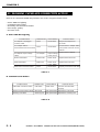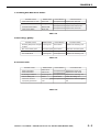
1
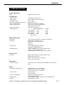
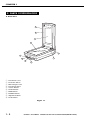
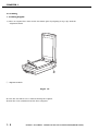
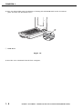
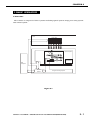
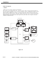
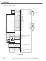
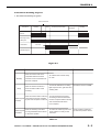
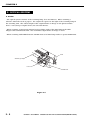
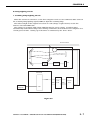
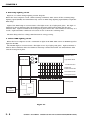
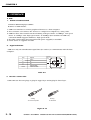
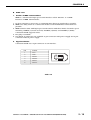
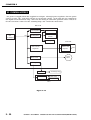
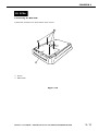
CS9900F SERVICE MANUAL Canon SERVICE MANUAL REVISION 0 CanoScan 9900F JPN USA EUR UK AUS CAN/CLA FEB. 2003 8132A001AA 8132A002AA 8132A003AA 8132A004AA 8132A005AA 8132A006AA UYW000001- JY8-1322-00Z COPYRIGHT 2003 CANON INC. CANOSCAN 9900F REV.0 FEB. 2003 PRINTED IN JAPAN (IMPRIME AU JAPON) COPYRIGHT © 2003 CANON INC. Printed in Japan Imprimè au Japon Use of this manual should be strictly supervised to avoid disclosure of confidential information. COPYRIGHT 2003 CANON INC. CANOSCAN 9900F REV.0 FEB. 2003 PRINTED IN JAPAN (IMPRIME AU JAPON) CONTENTS CHAPTER 1 : GENERAL DESCRIPTIONS SPECIFICATIONS ....................... 1-1 B. Unlocking the Lock Switch .. 1-6 II. PARTS CONFIGURATION ........... 1-2 C. Connecting the Cables ......... 1-6 A. Front View .......................... 1-2 D. Scanning ............................. 1-8 B. Back View ........................... 1-4 IV. CUSTOMER’S DAILY MAINTENANCE III. SETTING UP THE SCANNER ...... 1-5 ......................................... 1-12 I. A. Precautions ......................... 1-5 CHAPTER 2 : OPERATION AND TIMING I. BASIC OPERATION .................... 2-1 III. IMAGE PROCESSING ............... 2-12 A. Functions ............................ 2-1 A. Outline .............................. 2-12 B. Electrical System ................ 2-2 B. Image Processing ............... 2-13 C. Main PCB Input and Output . 2-4 IV. CONTROL SYSTEM .................. 2-20 A. Control System Diagram .... 2-20 D. Document Scanning Sequence B. Main PCB .......................... 2-20 ........................................... 2-5 II. OPTICAL SYSTEM ..................... 2-6 V. INTERFACE ............................. 2-21 A. Outline ................................ 2-6 A. USB ................................... 2-21 B. Lamp Lighting Circuit ......... 2-7 B. IEEE 1394 ......................... 2-24 C. FARE (Film Automatic Retouch- VI. POWER SUPPLY ....................... 2-24 ing and Enhancement) ......... 2-9 D. Motor Control Circuit ........ 2-11 CHAPTER 3 : MECHANICAL SYSTEM PARTS REPLACEMENT .............. 3-1 E. Attaching the Front Panel ...3-9 A. Precautions ......................... 3-1 III. PCBs ....................................... 3-11 II. EXTERNALS .............................. 3-2 A. Removing the Main PCB .... 3-11 A. Removing the Film Adapter Unit IV. OPTICAL SYSTEM ................... 3-14 I. ........................................... 3-2 B. Removing the Top Cover and A. Removing the Scanning Unit, Pulley Unit, and Motor Unit 3-14 Document Glass Unit ........... 3-3 B. Removing the Motor Unit .. 3-22 C. Attaching the Top Cover ...... 3-6 C. Attaching the Motor Unit .. 3-23 D. Removing the Front Panel ... 3-7 COPYRIGHT 2003 CANON INC. CANOSCAN 9900F REV.0 FEB. 2003 PRINTED IN JAPAN (IMPRIME AU JAPON) CHAPTER 4 : MAINTENANCE AND SERVICING I. PERIODICAL REPLACEMENT III. PERIODICAL SERVICING ........... 4-1 PARTS ....................................... 4-1 IV. SPECIAL TOOLS ........................ 4-1 II. CONSUMABLE PARTS V. SOLVENTS AND LUBRICANTS .... 4-1 DURABILITY .............................. 4-1 CHAPTER 5 : TROUBLESHOOTING I. INTRODUCTION ........................ 5-1 C. Scanning Unit Movement Failure A. Initial Check ....................... 5-1 ........................................... 5-5 B. Others ................................. 5-1 D. Poor Image Quality .............. 5-5 II. TROUBLESHOOTING FLOWCHART E. Acoustic Noise ..................... 5-5 ........................................... 5-2 IV. CANON SCANNER TEST ............. 5-6 A. Power LED Failure ............... 5-2 A. Outline ................................ 5-6 B. Communication Failure ....... 5-3 B. Operating Environment ....... 5-6 III. PROBLEM, CAUSE AND C. Functions ............................ 5-7 CORRECTIVE ACTION ............... 5-4 D. Functions Descriptions ....... 5-8 A. Power LED Not Lighting ....... 5-4 E. Error Message ................... 5-18 B. Communication Failure ....... 5-4 CHAPTER 6 : PARTS CATALOG FIGURE 001 .............................. 6-2 FIGURE 100 .............................. 6-4 APPENDIX I. GENERAL CIRCUIT DIAGRAM .... A-1 III. CCD PCB CIRCUIT DIAGRAM ... A-11 II. MAIN PCB CIRCUIT DIAGRAM ... A-2 COPYRIGHT 2002 CANON INC. CANOSCAN 8000F REV.0 OCT. 2002 PRINTED IN JAPAN (IMPRIME AU JAPON) CHAPTER 1 GENERAL DESCRIPTIONS I. SPECIFICATIONS ....................... 1-1 B. Unlocking the Lock Switch .. 1-4 II. PARTS CONFIGURATION ........... 1-2 C. Connecting Cables ............... 1-5 A. Front View .......................... 1-2 D. Scanning ............................. 1-6 B. Back View ........................... 1-3 IV. CUSTOMER’S DAILY MAINTENANCE III. SETTING UP THE SCANNER ...... 1-4 ........................................... 1-9 A. Precautions ......................... 1-4 COPYRIGHT 2003 CANON INC. CANOSCAN 9900F REV.0 FEB. 2003 PRINTED IN JAPAN (IMPRIME AU JAPON) CHAPTER 1 I. SPECIFICATIONS Scanner Main Unit Type : Flatbed image scanner Scanning Part Image sensor Light source Document type Document alignment position Max. document size Image output mode : : : : : : Optical resolution Scanning time Film Scanning Part Film type Film size Light source Scanning time Interface Part Interface Front Panel Scanner button Others Operating environment Power source Power consumption Dimensions Weight 14,240-pixel 6-line CCD Cold cathode fluorescent lamp Sheet, Book Right-end corner A4/Letter size (216 x 297mm) Color 16-bit/ 8-bit for RGB each Grayscale 16-bit/ 8-bit : 3200 dpi x 6400 dpi : USB2.0/IEEE1394 USB1.1 upto 200dpi 2.16 2.16 upto 400dpi 2.16 4.32 upto 800dpi 4.32 8.64 over 801dpi 8.64 17.28 (msec/ line) : Color and monochrome, negative and positive : 35mm sleeve (6 frames x 8) 35mm slide mount (24 frames) Brownie 4X 5 inch : Cold cathode fluorescent lamp IR LED (for FARE function) : USB2.0/IEEE1394:2.16-138.24msec/line USB1.1:2.16-146.88ms/line (automatically selected depending on films) : USB connector (Universal Serial Bus 2.0) IEEE-1394 connector Power connector (for AC adapter) FAU connector (6-pin) : 4 buttons (COPY, SCAN, FILE, E-MAIL) on the scanner unit : Temperature : 10 to 35 degrees Relative humidity : 10 to 90%RH Air pressure : 613 to 1013 hPa : 100V to 120V 220V to 240V : 21W max. (during operation) 8W (during standby) : 290.0 (Width) x 509.0 (Depth) x 127.3 (Height) mm : Approximately 5.3kg COPYRIGHT 2003 CANON INC. CANOSCAN 9900F REV.0 FEB. 2003 PRINTED IN JAPAN (IMPRIME AU JAPON) 1-1 CHAPTER 1 II. PARTS CONFIGURATION A. Front View 1 2 3 4 10 5 9 6 7 8 q w e r t y u i o !0 Document Cover Protective Sheet Film Adapter Unit Document Glass COPY Button SCAN Button FILE Button E-MAIL Button Alignment Mark Lock Switch Figure 1-1 1-2 COPYRIGHT 2003 CANON INC. CANOSCAN 9900F REV.0 FEB. 2003 PRINTED IN JAPAN (IMPRIME AU JAPON) CHAPTER 1 B. Back View 1 2 3 4 5 q w e r t Power Connector FAU Cable FAU Connector IEEE-1394 Connector USB Connector Figure 1-2 COPYRIGHT 2003 CANON INC. CANOSCAN 9900F REV.0 FEB. 2003 PRINTED IN JAPAN (IMPRIME AU JAPON) 1-3 CHAPTER 1 III. SETTING UP THE SCANNER A. Precautions * * * * * Keep the scanner out of direct sunlight. Direct exposure to the sunlight or excessive heat may cause damage to the scanner. Do not install the scanner in a humid or dusty environment. Use supplied AC adapter only. Place the scanner on an even and flat surface. Tilted or uneven surface may cause a mechanical problem. Keep the outer carton and packing material for future shipment. B. Unlocking the Lock Switch Scanning unit is locked by the lock switch to prevent a damage during transport. Unlock the lock switch by pushing it toward the “unlock” mark to use the scanner. 1 q Lock Switch Figure 1-3 Note : Ensure to lock the lock switch during transport. 1-4 COPYRIGHT 2003 CANON INC. CANOSCAN 9900F REV.0 FEB. 2003 PRINTED IN JAPAN (IMPRIME AU JAPON) CHAPTER 1 C. Connecting Cables CanoScan 9900F needs to be connected to the USB port on the host computer. For details, refer to the “Quick Start Guide” that comes with the product. As for connecting the host computer’s cables to the scanner, refer to the host computer' manual. Note: Install the device driver before connecting the cables. 1. Connecting FAU Cable, USB Cable, IEEE 1394 Cable and AC Adapter Cable 1) Connect the FAU cable to the FAU connector. 2) Connect the scanner with the host compter by either USB Cable or IEEE1394 Cable. Note: IEEE1394 Cable is not included. Use recommended cables. 3) Connect the AC adapter cable to the power connector on the scanner. 1 2 3 6 5 q w e r t y 4 USB Connector IEEE-1394 Connector Power Connector USB Cable IEEE-1394 Cable AC Adapter Figure 1-4 COPYRIGHT 2003 CANON INC. CANOSCAN 9900F REV.0 FEB. 2003 PRINTED IN JAPAN (IMPRIME AU JAPON) 1-5 CHAPTER 1 D. Scanning 1. Scanning Original 1) Place an original face-down on the document glass by aligning its top edge with the alignment mark. 1 q Alignment Mark Figure 1-5 2) Close the document cover without moving the original. 3) Send the scan command from the host computer. 1-6 COPYRIGHT 2003 CANON INC. CANOSCAN 9900F REV.0 FEB. 2003 PRINTED IN JAPAN (IMPRIME AU JAPON) CHAPTER 1 2. Scanning Film 1) Slide the protective sheet up and remove it from the document cover. Figure 1-6 2) Insert the film into the film guide. * Film strips Open the film holder on the film guide for film strips, insert the strip(s) face-down into the guide and close the film holder. * Slides Place a slide face down in the film guide for slides. * Open the film holder on the film guide for Brownie and 4X 5 inch, insert the strip(s) facedown into the guide and close the film holder. R R Figure 1-7 COPYRIGHT 2003 CANON INC. CANOSCAN 9900F REV.0 FEB. 2003 PRINTED IN JAPAN (IMPRIME AU JAPON) 1-7 CHAPTER 1 3) Place the loaded film guide by aligning its leading tab with FILM mark on the document glass and close the document cover. 1 q FILM Mark Figure 1-8 4) Send the scan command from the host computer. 1-8 COPYRIGHT 2003 CANON INC. CANOSCAN 9900F REV.0 FEB. 2003 PRINTED IN JAPAN (IMPRIME AU JAPON) CHAPTER 1 IV. CUSTOMER’S DAILY MAINTENANCE Dirt on the document glass may result in an unclear image or lines on an image. Clean the document glass according to the following steps. 1) Disconnect all the cables from the scanner. 2) Dampen a soft and clean cloth and wring it thoroughly. Wipe a dirt off the document glass with the cloth. 3) Completely wipe water off the document glass with a dry cloth. COPYRIGHT 2003 CANON INC. CANOSCAN 9900F REV.0 FEB. 2003 PRINTED IN JAPAN (IMPRIME AU JAPON) 1-9 CHAPTER 2 OPERATION AND TIMING I. BASIC OPERATION .................... 2-1 III. IMAGE PROCESSING ............... 2-12 A. Functions ............................ 2-1 A. Outline .............................. 2-12 B. Electrical System ................ 2-2 B. Image Processing ............... 2-12 C. Main PCB Input and Output . 2-4 IV. CONTROL SYSTEM .................. 2-17 D. Document Scanning Sequence A. Control System Diagram .... 2-17 ........................................... 2-5 II. OPTICAL SYSTEM ..................... 2-6 B. Main PCB .......................... 2-17 V. INTERFACE ............................. 2-18 A. Outline ................................ 2-6 A. USB ................................... 2-18 B. Lamp Lighting Circuit ......... 2-7 B. IEEE 1394 ......................... 2-19 C. FARE (Film Automatic Retouching VI. POWER SUPPLY ....................... 2-20 and Enhancement) .............. 2-9 D. Motor Control Circuit ........ 2-11 COPYRIGHT 2003 CANON INC. CANOSCAN 9900F REV.0 FEB. 2003 PRINTED IN JAPAN (IMPRIME AU JAPON) CHAPTER 2 I. BASIC OPERATION A. Functions The scanner is composed of three systems including optical system, image processing system, and control system. FAU FAU Lamp IR LED BGR Lamp Scanning Unit Lens B G R CCD Host Optical System Drive Motor FARE Unit Computer Control System Image Processing System Figure 2-1 COPYRIGHT 2003 CANON INC. CANOSCAN 9900F REV.0 FEB. 2003 PRINTED IN JAPAN (IMPRIME AU JAPON) 2-1 CHAPTER 2 B. Electrical System 1. Outline Figure 2-2 is an electric system circuit diagram. The scanner is not equipped with CPU. The device driver with a control program installed in the host computer functions as CPU. The host computer sends a command to the ASIC via the USB controller or IEEE 1394 controller. The ASIC controls the whole electrical circuits and image processing of the scanner. The image signals read by the CCD are converted into digital data by analog IC. The digital data is then processed by the ASIC and is output to the host computer via USB interface. Host Computer Control Program JP9 USB Controller JP9 IEEE-1394 Controller J1 Inverter PCB J2 +24V FAU Regulator Home Position AC adapter Sensor FAU Lamp Scanning Lamp JP2 Inverter PCB Button PCB Scanner Button Power LED ASIC JP1 CCD PCB DRAM Analog IC JP8 Motor Driver FARE Drive Motor Unit Figure 2-2 2-2 COPYRIGHT 2003 CANON INC. CANOSCAN 9900F REV.0 FEB. 2003 PRINTED IN JAPAN (IMPRIME AU JAPON) CHAPTER 2 2. Functions of Main PCB 1) Analog IC Converts the image signals (analog signals) read by CCD into digital data. - CDS (Correlated Double Sampling) - AGC (Auto Gain Control) - 8-bit A/D converter 2) ASIC Performs the following transactions: - DRAM control - CCD timing clock creation - Line buffer control - CCD output line difference adjustment - Image processing - Shading correction - Motor driver control 3) DRAM Stores the shading compensation data when performing shading compensation. Stores the image data when scanning. 4) Motor Driver Supplies power to the drive motor. 5) USB Controller/ IEEE 1394 Controller Controls data transfer between the host computer and ASIC. COPYRIGHT 2003 CANON INC. CANOSCAN 9900F REV.0 FEB. 2003 PRINTED IN JAPAN (IMPRIME AU JAPON) 2-3 CHAPTER 2 C. Main PCB Input and Output AC Adapter Scanning Unit J2-1 -2 -3 -4 -5 JP1-1 -2 -3 -4 -5 -6 -7 -8 -9 -10 -11 -12 -13 -14 -15 -16 -17 -18 -19 -20 -21 -22 -23 -24 -25 -26 -27 -28 Main PCB +24V +24V +24V NC GND LAMP_GND LAMP_GND LAMP_PWR LAMP_PWR CCD_PWR CCD_PWR AGND CCD_CK1 CCD_CK2 AGND VAROS_PWR AGND ASIC_VAROS B_TG CLB G_TG RB R_TG VCC AGND MTATHOME AGND AGND OUT_B AGND OUT_G AGND OUT_R J1-1 -2 -3 -4 -5 -6 -7 -8 To Film Scanning Unit Vbus DD+ GND JP9-1 -2 -3 -4 To Host Computer VP VG TPBN TPB TPAN TPA JP9-1 -2 -3 -4 -5 -6 XPA FAU_LED FAU_DET NC LMP_PWR XPAGND NC XPAGND To Host Computer Scanner button COPY JP2-1 -2 -3 -4 -5 -6 -7 -8 SCAN FILE E-MAIL HOTKEY0 HOTKEY1 "H" when Scanner button is HOTKEY2 pressed HOTKEY3 "H" when power LED is ON LED DGND DGND PWRSW Power LED Power Switch Button PCB Home Position Sensor "H" when scanning unit is in home position JP6-1 -2 Drive motor -3 -4 OUT1B OUT1A OUT2A Drive motor drive signal OUT2B Figure 2-3 2-4 COPYRIGHT 2003 CANON INC. CANOSCAN 9900F REV.0 FEB. 2003 PRINTED IN JAPAN (IMPRIME AU JAPON) CHAPTER 2 D. Document Scanning Sequence 1. Document Scanning Sequence Scan Command Sequence Standby Setup Scanning Unit forward Scanning Unit backward Standby Home Position Sensor Scanning Lamp ON Signal Drive Motor (Scans 9 lines for RGB each) Interface Signal Figure 2-4 Seqence Standby Setup Purpose Operation Remarks After the scanner self test is completed until the scanner receives a scan command from the host computer To maintain the scanner ready for scan From the scanner receives a scan command until it starts To execute calibration for setting The data is stored in DRAM light exposure time, gain data and shading data scanning After the scanner starts scanning Scanning Unit until whole scan area specified by the host computer is scanned Forward To execute image processing according to the command from the host computer while scanning and send imada data to the host computer Scanning Unit backward After the scanning unit starts moving backward until it returns to the home position To return the scanning unit to the home position to ready for the next scan Home position is detected by the home position sensor Table 2-1 COPYRIGHT 2003 CANON INC. CANOSCAN 9900F REV.0 FEB. 2003 PRINTED IN JAPAN (IMPRIME AU JAPON) 2-5 CHAPTER 2 II. OPTICAL SYSTEM A. Outline The optical system consists of the scanning lamp, lens and mirrors. When scanning a reflective materials such as papers , the original is exposed to the light of the scanning lamp in the scanning unit. The reflected light of the original forms an image on the photosensitive device, CCD (charge-coupled device) via lens and mirrors. When scanning transparent material such as films, Light of the FAU lamp in the Film Adapter Unit transmits the film. The transmitted light forms an image on CCD. When scanning with FARE function, IR LED instead of FAU lamp works to operate FARE unit. CCD Scanning Lamp Lens FARE Unit Figure 2-5 2-6 COPYRIGHT 2003 CANON INC. CANOSCAN 9900F REV.0 FEB. 2003 PRINTED IN JAPAN (IMPRIME AU JAPON) CHAPTER 2 B. Lamp Lighting Circuit 1. Scanning Lamp Lighting Circuit When the scanner is turned on, or the host computer sends a scan command, ASIC turns on the scanning lamp lighting signal (LAMP) to light the scanning lamp. The reflected light of the original is focused on CCD (charge-coupled device) via the five mirrors, lens and FARE unit. The scanner is equipped with a lamp OFF function for energy saving. A built-in timer automatically turns off the lamp if no scanning command is sent from the host computer for a certain period of time. Setting up of the timer is conducted by the device driver. Document Glass Scanning Lamp CCD Lens FARE Unit Scanning Unit Main PCB LAMP CCD GND Host PCB Inverter GND PCB ASIC Computer Figure 2-6 COPYRIGHT 2003 CANON INC. CANOSCAN 9900F REV.0 FEB. 2003 PRINTED IN JAPAN (IMPRIME AU JAPON) 2-7 CHAPTER 2 2. FAU Lamp Lighting Circuit Figure 2-7 is a FAU Lamp Lighting Circuit diagram. When the host computer sends a film scanning command, ASIC turns off the scanning lamp lighting signal (LAMP) and simultaneously turns on FAU lamp lighting signal (XPA) to light the FAU lamp. Light of the FAU lamp is converted into a flat light source by a light guide plate. The light is diffused by the1st diffusive film, the luminous intensity enhancement film and the 2nd diffusive film. Light transmitted the transparent plate all has the same luminous intensity as a result. Light transmits a film and is focused on the CCD in the scanning unit. The FAU lamp also has a lamp OFF function for energy saving. 3. Infrared LED Lighting Circuit When the host computer sends a command to light an IR LED, ASIC turns on IRLED signal to light the IR LED. The IR LED light is converted into a flat light source by a light guide plate. Light transmits a film via the1st diffusive film, the luminous intensity enhancement film, the 2nd diffusive film and the transparent plate. FAU FAU Lamp Reflective Film Light Guide Plate Inverter PCB IRLED 1st Diffusive Film Brightness Enhancement Film 2nd Diffusive Film Transparent Plate Scanner IRLED Scanning Unit XPA Host Computer ASIC Main PCB Figure 2-7 2-8 COPYRIGHT 2003 CANON INC. CANOSCAN 9900F REV.0 FEB. 2003 PRINTED IN JAPAN (IMPRIME AU JAPON) CHAPTER 2 C. FARE (Film Automatic Retouching and Enhancement) 1. Outline When scanning a film, it is difficult to obtain a clean image because of dirt and scrach on the film. CanoScan 9900F is equipped with the IR LED in addition to the FAU lamp (cold cathode fluorescent lamp) to remove scratches and dirt on a film by scanning a film by two light sources. This function is called FARE (Film Automatic Retouching and Enhancement). The IR LED scans only scratches and dirt on a film as image data. This data is compared to the full image data scanned by the FAU lamp, and the overlap data (that is of scratches and dirt) is deleted. The other scanned data of the film compensates for the deleted area, and the image without scratches and dirt is reproduced. (FAU LAMP) (IR LED) Light Source Film Lens CCD Scanned Image Figure 2-8 COPYRIGHT 2003 CANON INC. CANOSCAN 9900F REV.0 FEB. 2003 PRINTED IN JAPAN (IMPRIME AU JAPON) 2-9 CHAPTER 2 2. Operating FARE Function Two light sources mounted in CanoScan 9900F have different frequencies ( the FAU lamp (cold cathode fluorescent lamp): 380- 700nm, and IR LED : 880nm). If there light sources are used under the same optical system, the image will be out of focus(Figure 2-9-2). CanoScan 9900F is equipped with FARE unit. This unit is placed between the CCD and lens and is consists of a refraction glass that changes the refractive index of light and electromagnetic switch that change the position of the refraction glass. First, scan a film with light of the FAU lamp transmitting the refraction glass. Secondl, scan a film with the IRLED and turn on the electromagnetic switch to move the refraction glass to the position where no IR LED light can transmit the glass (Figure 2-9-3). Above functions make it possible to obtain the scanned image with the focus of light on the film while using two light sources with different frequencies. Light Source FAU Lamp IR LED IR LED Film Lens Refraction Glass (FARE Unit) CCD Figure 2-9-1 2 - 10 Figure 2-9-2 Figure 2-9-3 COPYRIGHT 2003 CANON INC. CANOSCAN 9900F REV.0 FEB. 2003 PRINTED IN JAPAN (IMPRIME AU JAPON) CHAPTER 2 D. Motor Control Circuit Figure 2-10 is a motor drive circuit diagram. Control program analizes a command sent from the host computer, and sends a motor clock generation command to ASIC. Gate array generates eight-phase motor drive pulse signals [I01, I02, I11, I12, I21, I22, I31, I32]. These signals are sent to the drive motor via motor driver. When the host computer changes the resolution, the control program commands ASIC to change the drive motor rotating speed by changing the frequency of the motor drive pulse signal . Host Computer Control Program Main PCB I01 I02 ASIC I11 Motor Driver OUT1B JP8-1 OUT1A -2 I21 OUT2A -3 I22 OUT2B -4 I12 Drive Motor I31 I32 Figure 2-10 COPYRIGHT 2003 CANON INC. CANOSCAN 9900F REV.0 FEB. 2003 PRINTED IN JAPAN (IMPRIME AU JAPON) 2 - 11 CHAPTER 2 III. IMAGE PROCESSING A. Outline Image processing system consists of the CCD, analog IC, and ASIC. Analog signal read by the CCD is converted into digital data, and the digital date is sent to the host computer. 1. CCD 2.. A/D Conversion 3. Calibration 4. Filter Processing To Host Computer Figure 2-11 B. Image Processing 1. CCD The CCD is a single chip photoelectric conversion device equipped with several thousand photosensitive devices. Each photosensitive devices is several microns square, and all devices are formed into a line to read RGB image signals with a built-in scanning circuit. CanoScan 9900F uses 6-line CCD. 1) 6-line CCD 6-line CCD has two rows of photosensitive devices in staggered arrangement for RGB each. This measn that the image with the resolution worth 1600dpi x 2 = 3200dpi can be scanned by only one scanning operation. Figure 2-12 2 - 12 COPYRIGHT 2003 CANON INC. CANOSCAN 9900F REV.0 FEB. 2003 PRINTED IN JAPAN (IMPRIME AU JAPON) CHAPTER 2 2. A/D Conversion Figure 2-13 is a block diagram that shows an internal processing of analog IC in the image processing system. Output signal s from the CCD are analog signals, and they cannot be used as image data. So, RGB output signal from the CCD is amplified by analog amplifier to generate analog data. The data is then converted into image data by A/D converter. D/A Converter CCD R G B Analog Amplifier A/D Converter Digital data To ASIC Analog IC Figure 2-13 1) D/A Converter D/A converter removes uneven data generated by the CCD' analog data. D/A converter adjusts CCD output to maintain a maximum value of input signal to A/D converter at 5V so that the black level of the image be constant. 2) A/D Converter A/D converter converts the black-level-corrected image signal (analog signal) into a 16-bit image data (digital signal) in the order of red, green and blue image signal. CanoScan 9900F uses 8-bit A/D converter. 5V is applied to the Vcc terminal, and reference voltage is applied to the Vref terminal. A/D converter outputs “0” when input signal is 5V, and outputs “255” when input signal equals to reference voltage. 1 pixel signal is converted into image data with 65536 tone for each colors including red, green and blue. Image Data A/D Converter Blue Image Signal Green Image Signal Red Image Signal Reference Voltage CCD_B CCD_G CCD_R Vref 0 1 0 1 0 1 0 1 Output 0 1 0 1 +5V Vcc 0 1 0 1 Figure 2-14 COPYRIGHT 2003 CANON INC. CANOSCAN 9900F REV.0 FEB. 2003 PRINTED IN JAPAN (IMPRIME AU JAPON) 2 - 13 CHAPTER 2 3. Calibration When scanning a document of even density, the image signal corresponding to each pixel may be uneven due to the following reasons: * Uneven light intensity of the scanning lamp * Variation in the sensitivity of the light phototransistors * A slight output from the light phototransistors with no light Calibration corrects these variations with the following three steps: Offset Calibration Coarse-gain Calibration Programmable Gain Amplifier (PGA). 1) Offset Calibration Normalize the output data from each pixel at the value of 0 or near 0 by using data aquired with no light. 2) Coarse-Gain Calibration Finds the optimum gain setting to have the output voltage from all pixels within in the adjustment range of Programmable Gain Amplifier. 3) Programmable Gain Amplifier (PGA) Calculates a gain coefficient to make output constant by correcting the output difference among pixels. 4. Filter Processing Changing the resolution and the scaling tends to reduce the image quality. To prevent this, the filter processing needs to be performed according to the resolution. The filter processing includes interpolation processing and averaging. 2 - 14 COPYRIGHT 2003 CANON INC. CANOSCAN 9900F REV.0 FEB. 2003 PRINTED IN JAPAN (IMPRIME AU JAPON) CHAPTER 2 1) Interpolation Processing When scanning at higher resolution, the image quality tends to be reduced. This is because one pixel output from the CCD is treated as two image data in the horizontal scanning direction, and one line output of the CCD is treated as two image data in the vertical scanning direction. The interpolation processing is performed to prevent the image quality reduction. Figure 2-15 shows a change in image density by the interpolation processing. A (A) B (B) C (C) D Interpolation processing A (A+B)/2 B (B+C)/2 C (C+D)/2 D Image Density 1 pixel Interpolation processing Image Density 1 pixel Figure 2-15 COPYRIGHT 2003 CANON INC. CANOSCAN 9900F REV.0 FEB. 2003 PRINTED IN JAPAN (IMPRIME AU JAPON) 2 - 15 CHAPTER 2 2) Averaging When scanning at lower resolution, the quality of output tends to be deteriorated. This is because data thining occures more frequently at lower resolution. Averaging is a process to average the data to be thinned and the data to be actually output to prevent the image deterioration. CCD reading A B C D E F G H A B C D E F G H B C D E F G H data Output image data Thinned data CCD A reading data Output image data A' E' Averaged data=(A+B+C+D)/4 Figure 2-16 2 - 16 COPYRIGHT 2003 CANON INC. CANOSCAN 9900F REV.0 FEB. 2003 PRINTED IN JAPAN (IMPRIME AU JAPON) CHAPTER 2 IV. CONTROL SYSTEM A. Control System Diagram Host Computer Control Program USB Controller IEEE-1394 Controller +12V Analog IC ASIC DRAM Main PCB AC Adapter Scanning Unit Inverter & Scanning Lamp Motor Driver Drive Motor Figure 2-17 B. Main PCB The scanner is not equipped with CPU. Control program in the device driver installed in the host computer includes a control program works as CPU. Control program sends a command to the ASIC in the main PCB, and the ASIC controls the entire scanning operation. The main PCB consists of ASIC, DRAM, USB controller, analog I/C and motor driver. COPYRIGHT 2003 CANON INC. CANOSCAN 9900F REV.0 FEB. 2003 PRINTED IN JAPAN (IMPRIME AU JAPON) 2 - 17 CHAPTER 2 V. INTERFACE A. USB 1. Outline of USB standard CanoScan 9900F employs USB2.0. Features of USB include: 1. USB is an interface to connect peripheral devices to a host computer. 2. Tree-structure can connect 127 devices to a single host computer by using "hub". 3. USB has three data transfer modes including "full speed mode" at 12Mbps, "low speed mode" at 1.5Mbps, and "high speed mode" at 480Mbps (new standard of USB 2.0.) CanoScan 9900F supports USB2.0's "high speed mode". 4. Hot plug (connectable/disconnectable with power supplied) is available. 5. Power source is supplied via USB. 2. Signal Definitons USB uses only two identification signal lines (D+ and D-) to communicate with the host computer. Pin 1 2 3 4 Shell Chassis Signal VBUS DD+ Signal GND Chassis GND 2 3 1 4 Table 2-2 3. Interface Connection USB connector has two plugs: A plug for upper layer and B plug for lower layer. A Plug To Host Computer B Plug To Scanner Figure 2-18 2 - 18 COPYRIGHT 2003 CANON INC. CANOSCAN 9900F REV.0 FEB. 2003 PRINTED IN JAPAN (IMPRIME AU JAPON) CHAPTER 2 B. IEEE 1394 1. Outline of IEEE 1394 Standard IEEE is a standard for high-speed serial interface called "Firewire" or "i.LINK" Features of IEEE 1394 includes: 1. No host computer is necessary as communication between peripherals is possible. 2. IEEE uses daisy chain as a connection method, and maximum 63 connections are possible. 3. IEEE transfers data with high-speed serial transfer with three kinds of transfer speed including 100Mbit/s (noted as S100), 200Mbit/s (S200), and 400Mbit/s (S400). CanoScan 9900F supports S100. 4. Hot plug is available. 5. Two kinds of connectors are available: 6-pin-connector with power supply and 4-pinconnector without power supply 2. Signal Definition CanoScan 9900F uses 6-pin-connector as an interface. PIN 1 2 3 4 5 6 SIGNAL VBUS GND Data BData B+ Data AData A+ 2 1 4 3 6 5 Table 2-3 COPYRIGHT 2003 CANON INC. CANOSCAN 9900F REV.0 FEB. 2003 PRINTED IN JAPAN (IMPRIME AU JAPON) 2 - 19 CHAPTER 2 VI. POWER SUPPLY DC power is supplied from the supplied AC adapter. Through power regulator, four DC power sources (+3.3V, +5V, +12V and +16.8V) are used in the circuit. +3.3V and +5V are supplied for the digital circuit and linear chip, +5V is for the Analog IC and home position sensor, +16.8V is for the CCD PCB, +12V is for the scanning lamp, and +24 for the motor drive. Main PCB 24V AC Adapter 12V +3.3V Regulator Digital Circuit +5V Regulator Home Position Sensor Analog IC CCD PCB 16.8V to 12V 24V to16.8V Regulator Regulator CCD Drive Motor Motor Driver +12V Regulator Inverter Scanning Lamp FAU Lamp Inverter IR LED FAU Figure 2-19 2 - 20 COPYRIGHT 2003 CANON INC. CANOSCAN 9900F REV.0 FEB. 2003 PRINTED IN JAPAN (IMPRIME AU JAPON) CHAPTER 3 MECHANICAL SYSTEM I. PARTS REPLACEMENT .............. 3-1 E. Attaching the Front Panel ... 3-9 A. Precautions ......................... 3-1 III. PCBs ....................................... 3-11 II. EXTERNALS .............................. 3-2 A. Removing the Main PCB .... 3-11 A. Removing the Film Adapter Unit IV. OPTICAL SYSTEM ................... 3-14 ........................................... 3-2 A. Removing the Scanning Unit B. Removing the Top Cover and the ......................................... 3-14 Document Glass Unit ........... 3-3 B. Removing the Motor Unit .. 3-22 C. Attaching the Top Cover ...... 3-4 C. Attaching the Motor Unit .. 3-23 D. Removing the Front Panel ... 3-5 COPYRIGHT 2003 CANON INC. CANOSCAN 9900F REV.0 FEB. 2003 PRINTED IN JAPAN (IMPRIME AU JAPON) CHAPTER 3 I. PARTS REPLACEMENT A. Precautions * Disconnect the AC adapter, USB cable, and FAU cable from the scanner before replacing the parts. * Wear anti-static gloves and grounding strap around the wrist during the work. * Follow the instructions. Do not remove any screw from the parts that need no replacement. * Store the removed parts in a clean place and do not displace them. * Assemble the scanner by following the replacement procedures backward, unless otherwise specified. * After replacement, check the quantity and shape of the replaced parts. COPYRIGHT 2003 CANON INC. CANOSCAN 9900F REV.0 FEB. 2003 PRINTED IN JAPAN (IMPRIME AU JAPON) 3-1 CHAPTER 3 II. EXTERNALS A. Removing the Film Adapter Unit 1) Disconnect the FAU cable. 2) Lift the film adapter unit as shown in Figure 3-1 to remove it. 1 2 q FAU Cable w Film Adapter Unit Figure 3-1 3-2 COPYRIGHT 2003 CANON INC. CANOSCAN 9900F REV.0 FEB. 2003 PRINTED IN JAPAN (IMPRIME AU JAPON) CHAPTER 3 B. Removing the Top Cover and the Document Glass Unit 1) Remove two screws that hold the Top Cover . 2) Remove the Top Cover by holding the front part of the cover and turning it toward the outside. 1 2 3 3 q Screw w Top Cover e Hook Figure 3-2 COPYRIGHT 2003 CANON INC. CANOSCAN 9900F REV.0 FEB. 2003 PRINTED IN JAPAN (IMPRIME AU JAPON) 3-3 CHAPTER 3 3) Slide the document glass unit backward and lift it. Remove the glass from the scanner. 1 q Document Glass Unit Figure 3-3 C. Attaching the Front Panel 1) Make sure that corners of the Top Cover and the Bottom Cover are aligned when screw them to the scanner. 3-4 COPYRIGHT 2003 CANON INC. CANOSCAN 9900F REV.0 FEB. 2003 PRINTED IN JAPAN (IMPRIME AU JAPON) CHAPTER 3 D. Removing the Front Panel 1) Remove the Front Panel from the scanner. (Refer to III-A Removing the Main PCB) 2) Remove the Top Cover and the Document Glass. 3) Remove the Carriage Unit and the Motor Unit (Refer to IV OPTICAL SYSTEM) 4) Remove a long screw in the center and two short screws on the edge. 5) Press two hooks until they make a snapping sound. 1 2 3 2 q Hook w Screw e Long Screw Figure 3-4 COPYRIGHT 2003 CANON INC. CANOSCAN 9900F REV.0 FEB. 2003 PRINTED IN JAPAN (IMPRIME AU JAPON) 3-5 CHAPTER 3 6) Press two hooks on both sides of the front panel inward. Remove the front panel and the button PCB unit from the main frame. 1 3 2 3 q Front Panel w Button PCB Unit e Hook Figure 3-5 3-6 COPYRIGHT 2003 CANON INC. CANOSCAN 9900F REV.0 FEB. 2003 PRINTED IN JAPAN (IMPRIME AU JAPON) CHAPTER 3 7) Cut off cable bands and disconnect cables from the main frame. Remove the button PCB unit. 1 q Cable Band Figure 3-6 COPYRIGHT 2003 CANON INC. CANOSCAN 9900F REV.0 FEB. 2003 PRINTED IN JAPAN (IMPRIME AU JAPON) 3-7 CHAPTER 3 8) Remove three screws and remove the button cable board. 1 2 3 q Screw w Button PCB e Lower Button Cover Figure 3-7 3-8 COPYRIGHT 2003 CANON INC. CANOSCAN 9900F REV.0 FEB. 2003 PRINTED IN JAPAN (IMPRIME AU JAPON) CHAPTER 3 E. Attaching the Front Panel 1) Pass the button cables through the main frame. 2) Fix cables to the main frames with cable bands as shown in Figure 3-8 1 q Cable Band Figure 3-8 COPYRIGHT 2003 CANON INC. CANOSCAN 9900F REV.0 FEB. 2003 PRINTED IN JAPAN (IMPRIME AU JAPON) 3-9 CHAPTER 3 3) Attach the button PCB unit to the main frame. 4) Insert the hook of the front panel to the main frame as shown in Figure 3-9. 1 1 q Hook Figure 3-9 5) Push the front part of the front panel until it makes a snapping sound. 3 - 10 COPYRIGHT 2003 CANON INC. CANOSCAN 9900F REV.0 FEB. 2003 PRINTED IN JAPAN (IMPRIME AU JAPON) CHAPTER 3 III. PCBs A. Removing the Main PCB 1) Turn the scanner over and remove four screws. 1 2 q Screw w Main PCB Figure 3-10 COPYRIGHT 2003 CANON INC. CANOSCAN 9900F REV.0 FEB. 2003 PRINTED IN JAPAN (IMPRIME AU JAPON) 3 - 11 CHAPTER 3 2) Lift the main PCB as shown in Figure 3-11 and disconnect the button cable and the motor unit cable. 2 1 q Motor Unit Cable w Button Cable Figure 3-11 3 - 12 COPYRIGHT 2003 CANON INC. CANOSCAN 9900F REV.0 FEB. 2003 PRINTED IN JAPAN (IMPRIME AU JAPON) CHAPTER 3 3) Turn the main PCB over. Remove screw that holds grounding and the flat cable. Remove the main PCB from the main frame. 3 2 1 q Main PCB w Flat Cable e Screw Figure 3-12 COPYRIGHT 2003 CANON INC. CANOSCAN 9900F REV.0 FEB. 2003 PRINTED IN JAPAN (IMPRIME AU JAPON) 3 - 13 CHAPTER 3 IV. OPTICAL SYSTEM A. Removing the Scanning Unit Note: Lens and mirrors of the scanning unit are factory adjusted. Do not touch the lamp, mirrors, and CCD PCB (shaded area shown in Figure 3-13) of the scanning unit. Figure 3-13 3 - 14 COPYRIGHT 2003 CANON INC. CANOSCAN 9900F REV.0 FEB. 2003 PRINTED IN JAPAN (IMPRIME AU JAPON) CHAPTER 3 1) Remove the main PCB. 2) Remove the top cover and the document glass unit. 3) Remove two screws and remove the cable cover. 1 2 q Screw w Cable Cover Figure 3-14 COPYRIGHT 2003 CANON INC. CANOSCAN 9900F REV.0 FEB. 2003 PRINTED IN JAPAN (IMPRIME AU JAPON) 3 - 15 CHAPTER 3 4) Slide the scanning unit from the home position by holding the edge of the unit as shown in Figure 3-15. Figure 3-15 3 - 16 COPYRIGHT 2003 CANON INC. CANOSCAN 9900F REV.0 FEB. 2003 PRINTED IN JAPAN (IMPRIME AU JAPON) CHAPTER 3 5) Remove two screws that hold the gear plate 2 . Remove spring from the gear plate 2. 6) Remove screw that holds grounding. 2 1 3 4 q w e r Grounding Cable Screw Spring Gear Plate 2 Figure 3-16 Note: When installing the gear plate 2, adjust the tension of the timing belt by spring hooked on the gear plate. Then fasten the gear plate on the sliding rod with screws. COPYRIGHT 2003 CANON INC. CANOSCAN 9900F REV.0 FEB. 2003 PRINTED IN JAPAN (IMPRIME AU JAPON) 3 - 17 CHAPTER 3 7) Remove two screws that hold the motor unit to the main frame. 2 1 q Grounding Cable w Screw Figure 3-17 3 - 18 COPYRIGHT 2003 CANON INC. CANOSCAN 9900F REV.0 FEB. 2003 PRINTED IN JAPAN (IMPRIME AU JAPON) CHAPTER 3 8) Push the sliding rod toward the front panel and slide the edge of the rod aside. Figure 3-18 COPYRIGHT 2003 CANON INC. CANOSCAN 9900F REV.0 FEB. 2003 PRINTED IN JAPAN (IMPRIME AU JAPON) 3 - 19 CHAPTER 3 9) Slide the slidng rod backward and lift it as shown in Figure 3-19. Disconnec the motor connector. Remove the sliding unit first and the scanning unit out of the main frame. 1 2 3 q Document Scanning Unit w Sliding Rod e Motor Connector Figure 3-19 3 - 20 COPYRIGHT 2003 CANON INC. CANOSCAN 9900F REV.0 FEB. 2003 PRINTED IN JAPAN (IMPRIME AU JAPON) CHAPTER 3 10) Remove the sliding rod and the timing belt from the scanning unit. 1 2 q Scanning Unit w Sliding Rod Figure 3-20 COPYRIGHT 2003 CANON INC. CANOSCAN 9900F REV.0 FEB. 2003 PRINTED IN JAPAN (IMPRIME AU JAPON) 3 - 21 CHAPTER 3 B. Removing Motor Unit 1) 2) 3) 4) Remove Remove Remove Remove the main PCB. the top cover and the document glass. the scanning unit. a screw that holds the sliding rod to the motor unit. 2 1 3 q Sliding Rod w Screw e Motor Unit Figure 3-21 3 - 22 COPYRIGHT 2003 CANON INC. CANOSCAN 9900F REV.0 FEB. 2003 PRINTED IN JAPAN (IMPRIME AU JAPON) CHAPTER 3 C. Attaching the Motor Unit 1) Apply grease (EM-50L) to the shaft of the gear when attaching the motor unit to the main frame. Make sure that no grease be applied to other parts. Figure 3-22 COPYRIGHT 2003 CANON INC. CANOSCAN 9900F REV.0 FEB. 2003 PRINTED IN JAPAN (IMPRIME AU JAPON) 3 - 23 CHAPTER 4 MAINTENANCE AND SERVICING I. PERIODICAL REPLACEMENT III. PERIODICAL SERVICING ........... 4-1 PARTS ....................................... 4-1 IV. SPECIAL TOOLS ........................ 4-1 II. CONSUMABLE PARTS V. SOLVENTS AND LUBRICANTS .... 4-1 DURABILITY .............................. 4-1 COPYRIGHT 2003 CANON INC. CANOSCAN 9900F REV.0 FEB. 2003 PRINTED IN JAPAN (IMPRIME AU JAPON) CHAPTER 4 I. PERIODICAL REPLACEMENT PARTS None II. CONSUMABLE PARTS DURABILITY None III. PERIODICAL SERVICING None IV. SPECIAL TOOLS None V. SOLVENTS AND LUBRICANTS Grease used for disassembly and reassembly of the scanner. Name Tool No. Usage : MOLYKOTE EM-50L : HY9-0007 : To be applied to the shaft of the gear of the motor unit and pulley unit. COPYRIGHT 2003 CANON INC. CANOSCAN 9900F REV.0 FEB. 2003 PRINTED IN JAPAN (IMPRIME AU JAPON) 4-1 CHAPTER 5 TROUBLESHOOTING I. INTRODUCTION ........................ 5-1 C. Scanning Unit Movement Failure A. Initial Check ....................... 5-1 ........................................... 5-5 B. Others ................................. 5-1 D. Poor Image Quality .............. 5-5 II. TROUBLESHOOTING FLOWCHART E. Acoustic Noise ..................... 5-5 ........................................... 5-2 IV. CANON SCANNER TEST ............. 5-6 A. Power LED Failure ............... 5-2 A. Outline ................................ 5-6 B. Communication Failure ....... 5-3 B. Operating Environment ....... 5-6 III. PROBLEM, CAUSE AND C. Functions ............................ 5-7 CORRECTIVE ACTION ............... 5-4 D. Functions Descriptions ....... 5-8 A. Power LED Not Lighting ....... 5-4 E. Error Message ................... 5-16 B. Communication Failure ....... 5-4 COPYRIGHT 2003 CANON INC. CANOSCAN 9900F REV.0 FEB. 2003 PRINTED IN JAPAN (IMPRIME AU JAPON) CHAPTER 5 I. INTRODUCTION A. Initial Check Check if the operating environment conforms to the following conditions. * * * * * Line voltage is within ±10% of the rated value. Ambient temperature and humidity conform to the operating environment. (Refer to CHAPTER 1, I. SPECIFICATIONS) The scanner is not placed near a water faucet, boiler, humidifier, open flame, or in dusty place. The scanner is not exposed to direct sunlight. If it is inevitable to place the scanner in a sunny place, hang a curtain to shield it from direct sunlight. The scanner is set up in a well-ventilated place. B. Others When moving the scanner from a cold place to a warmer place, condensation may be formed on the metal parts. Using the scanner with condensation on the body may result in a faulty operation. COPYRIGHT 2003 CANON INC. CANOSCAN 9900F REV.0 FEB. 2003 PRINTED IN JAPAN (IMPRIME AU JAPON) 5-1 CHAPTER 5 II. TROUBLESHOOTING FLOWCHART A. Power LED Failure Unlock Lock Switch Connect AC Adapter No Power LED is ON ? Table 5-1 Yes Connect USB cable Figure 5-2 Figure 5-1 5-2 COPYRIGHT 2003 CANON INC. CANOSCAN 9900F REV.0 FEB. 2003 PRINTED IN JAPAN (IMPRIME AU JAPON) CHAPTER 5 B. Communication Failure Scan Communication Yes Table 5-2 failed ? No Scanning Unit failed to move ? Yes Table 5-3 No Yes Poor Table 5-4 image quality ? No Acoustic noise originated ? Yes Table 5-5 No End Figure 5-2 COPYRIGHT 2003 CANON INC. CANOSCAN 9900F REV.0 FEB. 2003 PRINTED IN JAPAN (IMPRIME AU JAPON) 5-3 CHAPTER 5 III. PROBLEM, CAUSE AND CORRECTIVE ACTION Defects of CanoScan 9900F may fall into one of five categories listed below: * * * * * Power LED not lighting Communication failure Scanning unit movement failure Poor image quality Acoustic noise A. Power LED Not Lighting Possible Cause AC adapter is unplugged Related Parts Check Method None Visual check Corrective Action Plug the AC adapter into the outlet from the outlet AC Adapter cable is Visual check None Connect the AC adapter cable to the power connector on the disconnected from the scanner scanner AC adapter output voltage AC Adapter failure Output voltage Replace the AC adapter (+24V) check Button PCB failure Button PCB Tester check Replace the button PCB Main PCB failure Main PCB Tester check Replace the main PCB (+24V, GND) Main PCB connection failure Visual check None Properly connect the main PCB Table 5-1 B. Communication Failure Possible Cause USB cable connection failure Related Parts USB cable Check Method Visual check Corrective Action Connect the USB cable properly Scanner communication failure Main PCB Scanning unit failure Scanning unit Trial replacement Replace the main PCB Trial replacement Replace the scanning unit Table 5-2 5-4 COPYRIGHT 2003 CANON INC. CANOSCAN 9900F REV.0 FEB. 2003 PRINTED IN JAPAN (IMPRIME AU JAPON) CHAPTER 5 C. Scanning Unit Movement Failure Possible Cause Related Parts Check Method Corrective Action Drive belt broken or worn Drive belt Trial replacement Replace the drive belt Gears broken or worn Pulley Unit Trial replacement Replace the pulley unit Scanner button failure Button PCB Trial replacement Replace the button PCB Drive motor failure Motor unit Trial replacement Replace the motor unit Table 5-3 D. Poor Image Quality Related Parts Scanning lamp does not light Scanning unit Possible Cause Check Method Visual check Corrective Action Replace the scanning unit or blinks Dirt on document glass Main PCB failure CCD PCB failure Document glass Visual check Clean the document glass Main PCB Trial replacement Replace the main PCB Scanning unit Trial replacement Replace the scanning unit Table 5-4 E. Acoustic Noise Possible Cause Related Parts Check Method Corrective Action Motor unit failure Main PCB failure Scanning unit failure Dirt on sliding rod Reference sheet is improperly positioned Motor unirt Main PCB Scanning unit None Document glass Trial replacement Trial replacement Trial replacement Visual check Trial replacement Replace the motor unit Replace the main PCB Replace the scanning unit Clean the sliding rod Replace the document glass unit unit Table 5-5 COPYRIGHT 2003 CANON INC. CANOSCAN 9900F REV.0 FEB. 2003 PRINTED IN JAPAN (IMPRIME AU JAPON) 5-5 CHAPTER 5 IV. CANON SCANNER TEST A. Outline Canon Scanner Test is a utility software to check if faulty operation of CanoScan 9900F is caused by the hardware or the communication with the host computer. Windows : scantest.exe (Use of an English version or a Japanese version is determined by the Windows.) Macintosh : chk9900e (English) chk9900j (Japanese) B. Operating Environment The Canon Scanner Test requires following environment: Windows platform * CanoScan 9900F * PC/AT Compatibles (Pentium or later) * Windows 98/Me/2000/XP OS * CanoScan 9900F Device Driver Macintosh platform * CanoScan 9900F * Power Macintosh * Macintosh OS (Version 9.0 - 9.2) * CanoScan 9900F Device Driver Note: Install CanoScan 9900F device driver before the Canon Scanner Test. 5-6 COPYRIGHT 2003 CANON INC. CANOSCAN 9900F REV.0 FEB. 2003 PRINTED IN JAPAN (IMPRIME AU JAPON) CHAPTER 5 C. Functions 1. USB Information (Windows only) Information of the scanner connected to the USB port on the PC is displayed. If communication between the scanner and the host computer fails, no information will be displayed. 2. Scanner Information Control program of CanoScan 9900F connected to the PC is displayed. If communication between the scanner and the host computer fails, no information will be displayed. 3. Scanner Self Test CanoScan 9900F self test is executed. 4. Scan An image is scanned at any resolution and saved as an image file in the folder of Canon Scanner Test. 5. Film Scan Scann 35mm sleeve negative film by FAU lamp and scann it by IR LED with FARE function. Save the two scanned images files in the folder of Canon Scanner Test. Scann one frame at upper right in the sleeve film holder with resolution fixed at 1600dpi. Note: Calibration cannnot be used with CanoScan 9900F. (Calibration function is in light gray and unable to click it. ) COPYRIGHT 2003 CANON INC. CANOSCAN 9900F REV.0 FEB. 2003 PRINTED IN JAPAN (IMPRIME AU JAPON) 5-7 CHAPTER 5 D. Functions Descriptions 1. USB Information (Windows only) Select “USB Information” from the “Function” menu. The window shown in Figure 5-3 will appear. Figure 5-3 * * * * * Vendor Description Device Description Port Name Local Name USB Version 5-8 : : : : : Manufacture of the scanner, "Canon Inc." Product name, "CanoScan 9900F" Port name of the scanner recognized by Windows Product name, "CanoScan 9900F" USB version (USB1.1/USB2.0) that the scanner is operating with. COPYRIGHT 2003 CANON INC. CANOSCAN 9900F REV.0 FEB. 2003 PRINTED IN JAPAN (IMPRIME AU JAPON) CHAPTER 5 2. Scanner Information Select “Scanner information” from the “Function” menu The window shown in Figure 5-4 (Windows) or Figure 5-5 (Macintoch) will appear. Figure 5-4 Figure 5-5 * Vendor ID * Product ID * ROM Version : Manufacturer name of the scanner "CANON" : "IX-32015H"(CanoScan 9900F) : Firmware version of the control program of the scanner COPYRIGHT 2003 CANON INC. CANOSCAN 9900F REV.0 FEB. 2003 PRINTED IN JAPAN (IMPRIME AU JAPON) 5-9 CHAPTER 5 4. Scan Select "Scan" from the "Function" menu. The window shown in Figure 5-6 (Window) or Figure 5-7 (Macintosh) will appear. Figure 5-6 Figure 5-7 5 - 10 COPYRIGHT 2003 CANON INC. CANOSCAN 9900F REV.0 FEB. 2003 PRINTED IN JAPAN (IMPRIME AU JAPON) CHAPTER 5 Click "OK" to start scanner selftest. When completed normally, a dialog box shown in Figure 5-8 (Windows) or Figure 5-9 (Macintosh) will appear. Figure 5-8 Figure 5-9 When an error occurs, refer to "E. Error Message" to take a corrective action. COPYRIGHT 2003 CANON INC. CANOSCAN 9900F REV.0 FEB. 2003 PRINTED IN JAPAN (IMPRIME AU JAPON) 5 - 11 CHAPTER 5 4. Scanning Original Select “Scan” from the “Function” menu. The display will be either Figure 5-10 (Windows) or Figure 5-11 (Macintosh). Figure 5-10 Figure 5-11 5 - 12 COPYRIGHT 2003 CANON INC. CANOSCAN 9900F REV.0 FEB. 2003 PRINTED IN JAPAN (IMPRIME AU JAPON) CHAPTER 5 * Scan count Set the number to be scanned ranging from 1 to 100. * Resolution (dpi) When the resolution for scanning an image is set at 67/200/400dpi, the entire area of the document glass is scanned. When set at 800/1600/3200dpi, the are of 5mm in width from the reference sheet of the document glass is scanned. * Image handling When “Read in memory (no file)” is selected, the image is read into the memory and be destroyed. When “Save to TIFF file” is selected, the image is stored in the file called “img0.tif” in the folder of the Canon Scanner Test. When scan count is set at 2 or larger number, the scanned images are saved in more than one file including “img0.tif” file, “img1.tif” file , and “img2.tif” file. File space to be saved is as follow: 67 dpi : 1.3MB, 200 dpi : 11.2 MB, 400 dpi : 44.9 MB 800 dpi : 2.4 MB, 1600 dpi : 9.7 MB, 3200 dpi : 29.3 MB Note : Make sure that there are more disk space on HDD with Canon Scanner Test installed than ones specified above before scanning. COPYRIGHT 2003 CANON INC. CANOSCAN 9900F REV.0 FEB. 2003 PRINTED IN JAPAN (IMPRIME AU JAPON) 5 - 13 CHAPTER 5 5. Film Scan Select “Film Scan” from the “Function” menu. The window shown in Figure 5-12 (Windows) or Figure 5-13 (Macintosh) will appear. Figure 5-12 Figure 5-13 5 - 14 COPYRIGHT 2003 CANON INC. CANOSCAN 9900F REV.0 FEB. 2003 PRINTED IN JAPAN (IMPRIME AU JAPON) CHAPTER 5 Only an upper right frame of the 35mm sleeve film guide can be scanned (the first frame shown in Figure 5-14.) Figure 5-14 * Scan count Set a number to be scanned ranging from 1 to 100. When 2 or larger number is set and "Save to TIFF file" is selected, only a file of specified scanning is saved. * Image handling When “Read in memory (no file)” is selected, the image is read into the memory and be destroyed. When “Save to TIFF file” is selected, an image file scanned by FAU lamp and and an image file scanned by IR LED are saved. The images scanned by FAU lamp is stored in "Color24_0.tif" file, and the image scanned by IR LED is stored in "IR_0.tif" file. Both files are included in the folder of the Canon Scanner Test. IR.tif is an infrared image scanned with FARE function working. If FARE function works normally, only dirt or dust on the film will be scanned as an image. If FARE function does not work well, IR.tif image will be all in black. When scan count is set at 2 or larger number, the scanned images are saved in more than one file including Color24_0.tif/IR_0.tif, Color24_1. and tif/IR_1.tif. File space to be saved is as follow. Color24_0.tif (1600 dpi) : 10 MB, IR_0.tif (1600 dpi) : 3.3 MB Note: When scanning a film, the color of the scanned image may appear lighter than that of the original film. This is because the image is not subjec to the image processing yet. COPYRIGHT 2003 CANON INC. CANOSCAN 9900F REV.0 FEB. 2003 PRINTED IN JAPAN (IMPRIME AU JAPON) 5 - 15 CHAPTER 5 E. Error Message 1. “Unable to find the scanner. Check if the cables are connected properly.” Cause : Scanner is not detected by the host computer. Corrective Action : Refer to the “II. Troubleshooting Flowchart”. 2. “Failed to read scanner information.” Cause : Scanner is not detected by the host computer. Corrective Action : Refer to the “II. Troubleshooting Flowchart”. 3. “Failed to create a file.” “Failed to open a file.” “Failed to close a file.” “Failed to write-in a file.” Cause : Canon Scanner Test is started from a CD-ROM or write-protected HDD. Corrective Action : Copy the Canon Scanner Test on a writable HDD to use. 4. “Scanner has problem.” “Failed to execute scanner self test.” Cause : Scanner is not recognized by the host computer. Corrective Action : Refer to the “II. Troubleshooting Flowchart”. 5. “Failed to allocate memory.” Cause : Scanner is not recognized by the host computer. Corrective Action : Refer to the “II. Troubleshooting Flowchart”. 5 - 16 COPYRIGHT 2003 CANON INC. CANOSCAN 9900F REV.0 FEB. 2003 PRINTED IN JAPAN (IMPRIME AU JAPON) PRINTED IN JAPAN (IMPRIME AU JAPON) 0203N0.03-1 CANON INC. COPYRIGHT 2003 CANON INC. CANOSCAN 9900F REV.0 FEB. 2003 PRINTED IN JAPAN (IMPRIME AU JAPON)