1
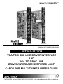
MULTI-TASKER™
MT103-127
MT103-128
MANUAL PART NUMBER: 400-0390-002
MT103-127/128
VGA TO 5 BNC LINE DRIVER/INTERFACE
AND
VGA TO 3 BNC LINE
DRIVER/INTERFACE/BUFFERED LOOP
CARDS FOR MULTI-TASKER USER’S GUIDE
MULTI-TASKER™
TABLE OF CONTENTS
Page
PRECAUTIONS / SAFETY WARNINGS.............. 2
GENERAL ................................ ......................... 2
INSTALLATION ................................ ................. 2
CLEANING ................................ ........................ 2
FCC / CE NOTICE................................ ............. 2
ABOUT YOUR MT103-127/128 ........................... 3
TECHNICAL SPECIFICATIONS .......................... 3
PRODUCT DESCRIPTION................................ .. 4
DESCRIPTION 1: MT103-127 ........................... 4
DESCRIPTION 2: MT103-128 ........................... 4
APPLICATION DIAGRAM................................ .... 5
DIAGRAM 1: MT103-127 TYPICAL SETUP ...... 5
DIAGRAM 2: MT103-128 TYPICAL SETUP ...... 5
DIAGRAM 3: MT103-127 INTERNAL VIEW ...... 6
DIAGRAM 4: MT103-128 INTERNAL VIEW ...... 7
DIAGRAM 5: MT103-127 SETTINGS ................ 8
DIAGRAM 6: MT103-128 SETTINGS ................ 9
INSTALLING YOUR MT103-127/128................. 10
OPERATION................................ ...................... 10
RS-232 CONTROL................................ .......... 10
DESCRIPTION OF COMMANDS .................... 10
SUMMARY OF COMMANDS........................... 15
MENU MODE ................................ .................. 16
TROUBLESHOOTING GUIDE........................... 18
NO DISPLAY ................................ ................... 18
ALTINEX POLICY................................ .............. 19
LIMITED WARRANTY/RETURN POLICY ....... 19
CONTACT INFORMATION.............................. 19
1
MULTI-TASKER™
PRECAUTIONS / SAFETY WARNINGS
1
•
This equipment has been tested and found to
comply with the limits for a Class A digital
device, pursuant to Part 15 of the FCC Rules.
These limits are designed to provide reasonable
protection against harmful interference when
the equipment is operated in a commercial
environment. This equipment generates, uses,
and can radiate radio frequency energy and, if
not installed and used in accordance with the
instruction manual, may cause harmful
interference to radio communications. Operation
of this equipment in a residential area is likely to
cause harmful interference in which case the
user will be required to correct the interference
at his own expense.
•
Any changes or modifications to the unit not
expressly approved by ALTINEX, Inc. could void
the user’s authority to operate the equipment.
Please read this manual carefully before using
your MT103-127/128. Keep this manual handy for
future reference. These safety instructions are to
ensure the long life of your MT103-127/128 and to
prevent fire and shock hazard. Please read them
carefully and heed all warnings.
1.1 GENERAL
•
Qualified ALTINEX service personnel, or their
authorized representatives must perform all
service.
1.2 INSTALLATION
•
To prevent fire or shock, do not expose this unit
to rain or moisture. Do not place the
MT103-127/128 in direct sunlight, near heaters
or heat radiating appliances, or near any liquid.
Exposure to direct sunlight, smoke, or steam
can harm internal components.
•
Handle the MT103-127/128 carefully. Dropping
or jarring can damage the card.
•
Do not pull the cables that are attached to the
MT103-127/128.
•
Insert the card carefully into the slots of the
Multi-Tasker™ without bending any edges.
1.3 CLEANING
•
Clean only the connector area with a dry cloth.
Never use strong detergents or solvents, such
as alcohol or thinner. Do not use a wet cloth or
water to clean the card. Do not clean or touch
any component or PCB.
1.4 FCC / CE NOTICE
•
This device complies with part 15 of the FCC
Rules. Operation is subject to the following two
conditions: (1) This device may not cause
harmful interference, and (2) this device must
accept any interference received, including
interference that may cause undesired
operation.
2
MULTI-TASKER™
ABOUT YOUR MT103-127/128
2
TECHNICAL SPECIFICATIONS
MT103-127/128
FEATURES/
DESCRIPTION
GENERAL
Inputs
Outputs
MT103-127
VGA TO 5 BNC LINE
DRIVER / INTERFACE
VGA TO 3 BNC LINE DRIVER /
INTERFACE / BUFFERED LOOP
MT103-128
The MT103-127/128 are high-resolution interfaces
designed to connect a computer video source to a
compatible monitor or projector over long
distances. The MT103-127/128 are compatible
with VGA thru UXGA resolutions.
Compatibility
Approvals
MT103-127/128
15-Pin HD Female
BNC Female (5)
RGBHV,RGBS, RGsB
BNC Female (3) RGsB
15-Pin HD Female RGBHV
VGA thru UXGA
CE/FCC
Table 1. MT103-127/128 General
MECHANICAL
Enclosure Slots Required
Weight
Connector Panel
T° Operating
T° Maximum
Humidity
MTBF (calc.)
The inputs on both cards are connected via a
standard computer VGA connector. The outputs
provided on the MT103-127 are RGBHV, RGBS or
RGsB. The Composite Sync and Sync on Green
signals are generated on board and may be
selected by the user. The MT103-128 provides
RGsB outputs and a buffered VGA local monitor
output on a standard 15-pin HD connector.
MT103-127/128
1
1.1 lb (0.5 kg)
Black Anodized
10°C-50°C
75°C
90% non-condensing
50,000 hrs
Table 2. MT103-127/128 Mechanical
The MT103-127/128 both use video signal
equalization and horizontal position controls to
compensate for signal quality loss on long cable
runs, up to 400ft between units. Switch settings
allow these features to be controlled either through
software control (RS-232) or from a hardware
adjustment accessible on the front of the card.
Signal Detection circuitry allows the user to
determine the presence of an input signal.
ELECTRICAL
Video Input Signals
Analog Signal Level
Impedance
Sync Input Signals
Impedance
Signal Level
Output Video Signals
Gain
Impedance
Output Sync Signals
Impedance
Signal Level
The HelpInside™ feature allows programmers to
have access to command structures and control of
the MT103-127/128 from any terminal.
The MT103-127/128 also has Menu driven
protocol implemented for easier RS-232 control,
which eliminates the requirement of typing lengthy
commands for output adjustments.
Power (from Enclosure)
MT103-127/128
MT103-127/128
RGB
1.5Vp-p Max.
75 Ohms
H,V
10kOhm
3-5V TTL
1.1
75 Ohms
75 Ohms
4.5V TTL
+6V
-6V
Power
388mA 129mA 3.0 watts
Table 3. MT103-127/128 Electrical
3
3
MULTI-TASKER™
PRODUCT DESCRIPTION
4
DESCRIPTION 2: MT103-128
DESCRIPTION 1: MT103-127
4
MULTI-TASKER™
APPLICATION DIAGRAM
5
DIAGRAM 1: MT103-127 TYPICAL SETUP
DIAGRAM 2: MT103-128 TYPICAL SETUP
5
MULTI-TASKER™
DIAGRAM 3: MT103-127 INTERNAL VIEW
6
MULTI-TASKER™
DIAGRAM 4: MT103-128 INTERNAL VIEW
7
MULTI-TASKER™
DIAGRAM 5: MT103-127 SETTINGS
MT103-127 SWITCH LOCATIONS AND SETTINGS
DEFAULTS: Horizontal Position = Hardware Control
Equalization
= Hardware Control
Composite Sync
= OFF (Closed)
Sync Delay
= ON
Sync On Green
= OFF
8
MULTI-TASKER™
DIAGRAM 6: MT103-128 SETTINGS
MT103-128 SWITCH LOCATIONS AND SETTINGS
DEFAULTS: Horizontal Position = Hardware Control
Equalization
= Hardware Control
Sync Delay
= ON
9
MULTI-TASKER™
INSTALLING YOUR MT103-127/128
6
OPERATION
Step 1. Determine the switch settings before
installing the MT103-127/128. The switch
settings determine the following:
7.1 RS-232 CONTROL
When used in the Multi-Tasker™ Enclosure, the
MT103-127/128 has many advanced remote
control capabilities, which are accessible through
standard RS-232 communication. The act ual
controlling can be accomplished through a
computer control system or any other device
capable of sending RS -232 commands.
MT103-127 and MT103-128
Equalization: Set for hardware or
software control.
Horizontal
Set for hardware or
Position:
software control.
Sync Delay: Set Sync Delay On/Off for
Horizontal Position control.
7.1.1 RS-232 INTERFACE
The
RS-232
commands,
for
the
MT103-127/128, are in a simple ASCII
character format.
MT103-127 ONLY
Sync On
Set Sync-On-Green ON or
Green:
OFF.
Composite
Sync:
7
Set for HV Sync or
Composite Sync.
Step 2. Set the switches. See the switch
locations for the MT103-127 on page 8,
DIAGRAM 5, and the switch locations for
the MT103-128 on page 9, DIAGRAM 6.
1.
Square brackets “[
command.
]” are part of the
2.
Use uppercase letters for all commands.
After processing a command, an OK or ER will
be returned as feedback if "F" is included at the
end of a command string.
Step 3. Slide the MT103-127/128 into an
available slot in the Multi-Tasker™
Enclosure in order to connect to the bus.
Make sure that the card fits into place.
Secure the card to the Multi-Tasker™ by
tightening the retainer screws located on
the top and bottom of the card .
Commands ending in "S" will be saved into
memory. Commands not ending in "S" will still
be executed but will not be restored when the
system is reset or powered OFF then ON.
7.2 DESCRIPTION OF COMMANDS
Each command consists of three
Function, Card ID, and Unit ID.
[ Function , Card ID , Unit ID ]
Step 4. Connect the MT103-127/128 input
connector to a computer output using a
standard VGA type cable. Connect the
output connectors to the display device
using the appropriate BNC type cables.
parts:
Example: [VERC3U2]
VER = Function
C3 = Card ID or Group ID
U2 = Unit ID
Step 5. For the MT103-128 only, connect the
local monitor output to a local monitor for
display purposes.
For Function, see a detailed explanation under
each command description.
Step 6. Starting from the left, identify the slot
number where the MT103-127/128 card
is plugged into the Enclosure and note
that it is for RS-232 control.
Step 7. Reset the Multi-Tasker™ or turn the
power off and then on.
10
MULTI-TASKER™
The Card ID is an assigned value. It is equal to
the enclosure slot number in which the card is
installed. The value can range from 1 to 4 up to
1 to 20 depending on the enclosure.
2. [C]
This command displays the card status.
Command Format: [CnUi]
Cn = Card ID (n = # from 1 to max slots)
Card ID 0 (C0) is used for the controller. See
the MT100-100 User’s Guide for details.
Ui = Unit ID (i = # from 0 to 9)
The Group ID is a number representing a group
of cards defined with the [WR] command.
When using the Group ID, all cards in the group
will perform the given instruction.
Example:
One MT103-127/128 card is in slot #4. Send
the command [C4] and receive feedback similar
to the following:
Changing the position of a card will significantly
affect the commands recorded on software
definitions or third party control systems.
ON,EQ=1,HP=10 C04
ON
= Output is enabled (always on)
EQ = 1
= Equalization level is 1 (out of 50)
Horiz Pos = Horiz Position is 10 (out of 20)
Note: If there is no card in slot #4, sending the
[C4] command will not return any feedback.
The Unit ID has a value from 0 to 9. Unit ID 0
should be used for single unit operation. If the
Unit ID is set to zero, each command may be
used without Ui. Use the command [SETU0],
as explained in the MT100-100 User’s Guide.
3. [CnS]
Example:
This command saves the Equalization and
Horizontal Position settings. These values will
be restored after Reset or power up.
[VERC3]:
For Unit ID Zero
[VERC3Ui]: For Unit ID other than Zero
[VERC3]:
Equivalent to [VERC3U0]
Command Format: [CnUiS]
1. [VER]
This command displays the software version
and card type for the MT103-127/128 card.
Cn = Card ID (n = slot # from 1 to max slots)
Command Format: [VERCnUi]
S
Cn = Card ID (n = slot # from 1 to max slots)
Example:
Ui = Unit ID (i = # from 0 to 9)
Example:
Save the settings on the card from the previous
command example. The feedback after sending
the command [C4S], for slot 4, would be:
An MT103-128 card is in slot #4. Send the
command [VERC4], and the Multi-Tasker™
Enclosure will return the following feedback:
ON,EQ=1,HP=10 C04 Saved
Ui = Unit ID (i = # from 0 to 9)
4. [CLR]
MT103-128 690-0197-001
MT103-128
= Save settings
This command is used to clear the card and
return it to its factory settings. The default
values are Equalization equal to zero and
Horizontal Position equal to 10.
= the card model
690-0197-001 = the software version
Command Format: [CLRCnUi]
Cn = Card ID (n = # from 1 to max slots)
Ui = Unit ID (i = from 0 to 9)
11
MULTI-TASKER™
Example:
Feedback Prefix Definitions:
+MT = Multi-Tasker Card
+VR = Firmware Version
+ON = ON/OFF Status
+EQ = Equalization Setting
+SI = Signal Present
Send the command [CLRC4] to restore the card
in slot #4 to its factory defaults. Send the
command [C4] after the [CLR] command the
receive the following feedback:
ON,EQ=0,HP=10 C04
Example 1:
5. [?]
Command =
Feedback =
+EQ
25
C04
This command will return general information
about the card and the status.
Command Format: [?CnUi]
Cn = Card ID (n = # from 1 to max slots)
NOTE:
Ui = Unit ID (i = from 0 to 9)
[EQ=25C4]
+EQ25C04
= Equalization
= Equalization setting
= Card slot number
See the [?] command for further
details.
7. [TEST]
Example:
Send the command [?C4] to receive the
feedback for the MT103-128 in slot #4. Each
status field begins with a '+' and ends with the
card slot number (ex: C04). The feedback will
be similar to the following:
This command performs a test on the internal
memory. If there are problems, failures will be
indicated. Otherwise, the system will display the
following:
[+MT103-128C04+VR690-0197-001C04
+ONC04+EQ0C04+SI0C04]
Command Format: [TESTCnUi]
MT103-128
VR690-0197-001
ON
EQ0
SI1
=
=
=
=
=
MEMORY IC GOOD
Cn = Card ID (n = slot # from 1 to max slots)
Card Type
Firmware version
ON/OFF Status
Equalization = 0
Signal Detect = 1, an
input signal is detected.
Ui = Unit ID (i = # from 0 to 9)
Example:
There is an MT103-127/128 in slot #4. In order
to test the internal memory, send the command
[TESTC4].
6. [STA]
8. […S] – SAVE
This command enables/disables automatic
feedback from the front panel. The feedback
will be displayed following the command sent.
The command affects any card with
auto-feedback
capability,
not
just
the
MT103-127/128. The default at power on or
reset is STA0, OFF.
This command will save the configuration
command being sent in memory.
When
sending the command [EQ=25C4S], after reset
or power up, the Equalization will be set to 25
for the card in slot #4.
9. […F] – FEEDBACK
Command Format [STA1] = ON
Command Format [STA0] = OFF
After processing a command, an OK or ER will
be returned as feedback if "F" is included at the
end of a command string.
12
MULTI-TASKER™
SET AN ABSOLUTE VALUE
10. [SIG]
Command Format: [EQ=mCnUi]
The Signal Present command tests for the
presence of an input signal. The card returns
either a "1" or a "0" as feedback.
m
= EQ Value (m = # from 0 to 50)
Cn = Card ID (n = slot # from 1 to max slots)
1 = Signal detected
0 = No signal detected
Ui = Unit ID (i = # from 0 to 9)
Command Format: [SIGCnUi]
Example:
Cn = Card ID (n = # from 1 to max slots)
Send the command [EQ=25C4] to set the
equalization value to 25. The [+] and [-]
commands may be used immediately following
the EQ command for further adjustment.
Ui = Unit ID (i = # from 0 to 9)
Example:
12. [HP]
There is a properly formatted input signal being
applied to the card in slot 4. Check for the
presence of an input signal by sending the
command [SIGC4]. The feedback will be a "1"
immediately following the command sent:
This command is used to set the Horizontal
Position (HP). The position may be set either to
an absolute number specified by the user or
incremented and decremented in steps using
the [+] and [-] commands.
[SIGC4]1
[SIGC4]
1
= the command sent
= feedback, signal is present
ADJUST INCREMENTALLY
Command Format: [HPCnUi]
11. [EQ]
Cn = Card ID (n = slot # from 1 to max slots)
This command is used to set the equalization
(EQ). The equalization may be set either to an
absolute number specified by the user or
incremented and decremented in steps using
the [+] and [-] commands.
Ui = Unit ID (i = # from 0 to 9)
Example:
If there is an MT103-127/128 in slot #4, send
the command [HPC4] to make Horizontal
Position the active command. Then use the [+]
and [-] commands to adjust. See the [+] and [-]
commands for further details.
ADJUST INCREMENTALLY
Command Format: [EQCnUi]
Cn = Card ID (n = slot # from 1 to max slots)
SET AN ABSOLUTE VALUE
Ui = Unit ID (i = # from 0 to 9)
Command Format: [HP=mCnUi]
Example:
m
If there is an MT103-127/128 in slot #4, send
the command [EQC4] to make Equalization the
active command. Then use the [+] and [-]
commands to adjust. See the [+] and [-]
commands for further details.
= EQ Value (m = # from 0 to 20)
Cn = Card ID (n = slot # from 1 to max slots)
Ui = Unit ID (i = # from 0 to 9)
Example:
Send the command [HP=10C4] to set the
equalization value to 10. The [+] and [-]
commands may be used immediately following
the HP command for further adjustment.
13
MULTI-TASKER™
In Multi-Tasker™ systems with audio and video
cards, boards are typically grouped as follows:
13. [ + ] and [ – ]
These commands are used to adjust the
Equalization and Horizontal Position and may
be used from keyboard commands or
programmed front panel buttons.
Group 1 = Video Cards
Group 2 = Audio Cards
Group 3 = Video and Audio Cards
If assigning group commands to button
functions, it is best to use the "Press and Hold
on Power Up" to make group settings.
Command Format: [ + ], [ - ]
[+] = Increment level by one step
[-]
= Decrement level by one step
Command Format: [WRCn…GkUi]
Example:
Cn = Card ID (n = slot # from 1 to max slots)
Select the Horizontal Position control for the
card in slot #4. The current setting is 5, but it is
not the optimal value. After sending the
following commands, an optimum setting of 10
is obtained:
1.
[EQC4]
The current level is 5.
2.
[–][–][–]
The level is now 2 and is too low.
3.
[+][+][+][+][+][+][+][+]
The level is now 10 and no further
adjustments are required.
Gk = Group ID (k = # from 1-8)
Ui = Unit ID (i = # from 0-9)
Example:
To group cards 1, 2, and 3 as group 5 of
Unit ID
1,
send
the
command
[WRC1C2C3G5U1]. After executing this
command, cards 1, 2 and 3 will be grouped
together as group 5 of Unit ID 1. The system
will return the following feedback:
G1=C1C2C3
Now, when a command is sent to G1, each
board in G1 will execute the same command.
14. [HELP]
16. [CLRG]
This command displays information available
for the Multi-Tasker interface commands.
This command clears the members for a single
group or for all groups. The clear command
restores the cards to default settings.
Command Format: [HELPCnUi]
Cn = Card ID (n = # from 1 to max slots)
Command Format: [CLRGkUi]
Ui = Unit ID (i = # from 0 to 9)
Gk = Group ID (k = # from 1-8, or [ for all)
Example:
Ui = Unit ID (i = # from 0-9)
In order to display the RS-232 commands
available for the MT103-127/128 card in slot #4,
send the command [HELPC4]. The commands
along with a brief description will be displayed
in the Terminal Window.
Example:
15. [WR]
This command groups multiple cards in the
enclosure allowing all the group members to be
controlled simultaneously with the same
command. Each unit may define a maximum of
eight groups.
1)
To clear group 1, send the [CLRG1U1]
command. This command clears the
members for the specified group only.
2)
To clear all groups of Unit ID 1, send the
[CLRG[U1] command.
NOTE: Since this command is sending the
[CLR] command to its group members,
each card will display its own reset
message.
14
MULTI-TASKER™
17. [RD]
7.3 SUMMARY OF COMMANDS
This command displays the members in each
group.
Card Commands
1)
[VER]
Receives software version
2)
[C]
Receives status of the card
3)
[CnS]
Saves card settings
4)
[CLR]
Reset card to default values
5)
[?]
Show status/ general information
6)
[STA]
Enable/disable auto feedback
7)
[TEST] Test internal memory IC's
8)
[…S]
Save the command configuration
G1=C1C2C19
9)
[…F]
Provides feedback upon sending
The feedback shows G1 (Group 1) and then the
cards that make up Group 1. In this case,
Group 1 includes C1, C2 and C19.
10) [SIG]
Input Signal Detect
11) [EQ]
Set/adjust equalization
12) [HP]
Set/adjust Horizontal Position
13) [ + ]
Increments and Decrements
Command Format: [RDGkUi]
Gk = Group ID (k = # from 1-8)
Ui = Unit ID (i = # from 0-9)
Example:
The cards in slots 1, 2 and 19 are part of
group 5 in Unit ID 1. Read the member data for
group 5 of Unit ID 1, by sending the command
[RDG5U1]. The system will return feedback as
follows:
18. [CLM]
This command removes the members in a
group and leaves the group empty.
[-]
selected commands
Command Format: [CLMGkUi]
14) [HELP] Display all available commands
Gk = Group ID (k = # from 1-8)
Group Commands
Ui = Unit ID (i = # from 0-9)
15) [WR]
Example:
16) [CLRG] Clears group members
Group 5 of Unit ID 1 contains the cards in slots
1, 2 and 19. Read the member data for group 5
of Unit ID 1. Send the command [RDG5U1]
and receive the following feedback:
17) [RD]
Displays group members
18) [CLM]
Removes members from group.
G1=C1C2C19
Now, clear group 5 by sending the command
[CLMG5U1]. Reread the member data as above
and note the following feedback:
G1=EMPTY - PLEASE RESET THE SYSTEM
WHEN FINISHED
15
Groups multiple cards
MULTI-TASKER™
7.4 MENU MODE
7.4.2 USING MENU MODE
MENU MODE commands are RS-232 commands
that allow virtually the same functionality as
programming commands. Unlike the programming
commands in the previous sections, 7.2 and 7.3,
MENU commands prompt the user to select from a
list of available options. The system then responds
based upon selections made by the user.
SUGGESTION: Before using the menu mode, it
is best to disable the automatic feedback
feature. The values and current settings will be
displayed in the menu mode, but the automatic
feature will display after each setting change
making the menus difficult to read.
1.
In order to enter MENU mode, the system
needs to be connected to a computer
running MTSetup™ or other RS-232 control
software.
2.
Insert the card into an empty slot and push
in all the way for a secure fit.
3.
Reset the system or power the system OFF
and then ON.
4.
In MTSetup™, click the cursor in the
Terminal Window and press the ENTER
key.
5.
The system will interrogate the enclosure
and return a list of cards installed and their
slot locations.
MENU commands may be issued in response to
prompts from within MTSetup™ or other RS -232
communication software.
The MENU driven commands are only available
with Multi-Tasker™ Front Panel systems that have
the following firmware:
690-0122-015 = Version 015 or later.
690-0123-004 = Version 004 or later.
690-0124-015 = Version 018 or later.
NOTE: In MTSetup™, send the command [VER]
from the Terminal Window. The system will
respond with feedback similar to the following:
[690-0122-015 690-0123-004 690-0124-018]
Check the last three digits against the numbers
above to determine if the MENU MODE option is
available.
Example: 8 (Slot 8): MT103-127
NOTE: Only cards supporting the MENU
feature will be displayed.
7.4.1 MENU COMMAND DEFINITIONS
Refer to section 7.2 for details on card functions
and examples. Following is a cross-reference of
menu mode sections versus programming
commands.
MENU
Control
Clear
Setup
Equalization
Horiz Pos
Status
Help
Not Available
5.
Find
the
alphanumeric
character
representing the card whose setup requires
changing. It will be the first character in the
line.
6.
Press the number or letter associated with
the card, and a menu with options available
for that card will appear on the screen. In
the example above, press "8".
COMMAND
[CLR]
WARNING: Do NOT enter any characters
except the one relating to the desired
menu. Pressing ENTER or RETURN after
"8" will force the system back to the original
prompt.
[EQ], [+], [-]
[HP], [+], [-]
[VER], [C]
[HELP]
[?], [CnS], [STA], […S], [...F],
[TEST], [WR], [CLM],
[CLRG], [RD]
7.
16
After selecting the MT103-127/128 as
described above, the system will prompt for
selections specific to that card.
MULTI-TASKER™
8.
Read each menu carefully, and continue
selecting keys as prompted for further
functions. (Example prompt: "Key= ")
MT103-127/128 MAIN MENU
PRESS KEY TO SELECT
1: CONTROL
2: SETUP
3: STATUS
4: HELP
ESC: GO BACK
7.4.3 MENU TYPES
1.
MAIN MENU
The first menu displayed after selecting the
card is the Main Menu. This menu provides
access to the main functions related to the
card. Press the key representing the menu
item for access. A sub menu will appear
next.
2.
KEY=
MT103-127/128 EXPANDED MENUS
1. CONTROL: THIS CARD
SUB MENUS
Each sub menu will display either another
menu (sub menu) or a list of available
options or settings. Press the key
corresponding to the menu choice to
change a setting or select the next menu.
1: CLEAR
ESC: GO BACK
KEY=
2: SETUP
1: SET EQUALIZATION
SET EQUALIZATION (EQ=2)
NOTE: Pressing the ESCAPE (ESC) key in
most menus will take you up to the
previous menu. In some case, it returns to
the previous menus without making
changes in the current menu.
1: INCREASE EQ
2: DECREASE EQ
ESC: GO BACK
7.4.4 MT103-127/128 MENUS
Following are the menus available to the
MT103-127/128. The first menu is the Main
Menu only. The second listing is an expansion
of all the menu items available.
KEY=
Pressing 1 or 2 at the "Key=" prompt
will increment or decrement the EQ
setting and display the new value.
2: SET HOR POSITION
SET HORIZONTAL POSITION (HP=10)
The expanded menu contains values in
parentheses that indicate the current setting or
value of that parameter. These are only
examples and will vary from card to card. In
some areas, additional comments are provided
for clarification. These comments will appear in
normal text format either just prior to the menu
item or just after.
1: ADJUST TO LEFT
2: ADJUST TO RIGHT
ESC: GO BACK
KEY=
Pressing 1 or 2 at the "Key=" prompt
will increment or decrement the HP
setting and display the new value.
ESC: GO BACK
KEY=
CAUTION: Pay special attention to the top of
the menus. Current values and settings will be
displayed in parentheses.
17
MULTI-TASKER™
3: STATUS
Equivalent to the [VER] and [C] commands.
Returns the card number, firmware revision
and status.
4: HELP
Equivalent to the [HELP] command.
Displays a list of commands available for
the MT103-127/128 along with a brief
description.
ESC
Returns to the parent menu.
3. Display Card Status
Starting from the
keystrokes below.
3
Displays card status
TROUBLESHOOTING GUIDE
8
We have carefully tested and have found no
problems in the supplied MT103-127/128;
however, we would like to offer suggestions for the
following:
8.1 NO DISPLAY
7.4.5 MENU MODE EXAMPLES
Cause 1: The source has a problem.
All MENU MODE examples assume an
MT103-127/128 is installed in slot #1. Start by
clicking the mouse in the Terminal window.
Press ENTER and a list of available cards will
be displayed.
Solution:
1. Reset the card to factory default settings
Follow the keystrokes below:
Enter
1
1
1
1
ESC
Main Menu, follow the
Check the source and make sure
that there is a signal present and all
source connections are correct. If
the source is working and there is
still no display, see Cause 2.
Cause 2: Cable
connections
to
destination are incorrect.
List available cards
Select MT103-127/128 in slot #1
Select the CONTROL menu
Select CLEAR
YES to confirm clear
Return to the MAIN Menu
Solution:
the
Make sure that cables are
connected properly. Also, make
sure that the continuity and wiring
are good. If there is still no display
present, see Cause 3.
Cause 3: The display has a problem.
2. Set the Equalization to 25, starting at 20
Starting from the Main Menu, follow the
keystrokes below.
2
1
1
1
1
1
1
ESC
ESC
Solution:
Select SETUP menu
Select SET EQUALIZATION
Increment by 1
Feedback returns EQ=21
Increment by 1 (EQ=22)
Increment by 1 (EQ=23)
Increment by 1 (EQ=24)
Increment by 1 (EQ=25)
Return to SETUP menu
Return to the Main Menu
18
Make sure that the display is
powered. If there is still no display,
call ALTINEX at (714) 990-2300.
MULTI-TASKER™
ALTINEX POLICY
9
9.1 LIMITED WARRANTY/RETURN POLICY
Please
see
the
Altinex
website
at
www.altinex.com for details on warranty and
return policy.
9.2 CONTACT INFORMATION
ALTINEX, INC
592 Apollo Street
Brea, CA 92821 USA
TEL: 714 990-2300
TOLL FREE: 1-800-ALTINEX
WEB: www.altinex.com
E-MAIL: [email protected]
19