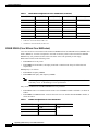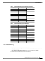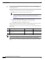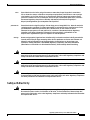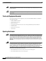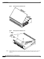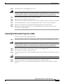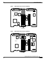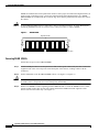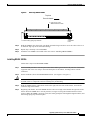
1
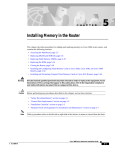
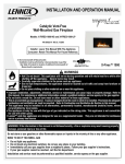
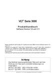
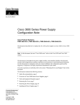
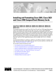
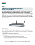
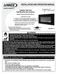
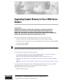
Upgrading System Memory in Cisco 3600 Series
Routers
Product Numbers:
MEM3600-4FS=, MEM3600-8FS=, MEM3600-16FS=, MEM3600-32FS=, MEM3620-4D=, MEM3620-8D=,
MEM3620-16D=, MEM3631-32CF-INCL, MEM3631-32U64CF, MEM3631-32U128CF, MEM3631-64CF=,
MEM3631-128CF=, MEM3631-64D-INCL, MEM3631-64U128D, MEM3631-64U192D, MEM3631-64U256D,
MEM3631-64D=, MEM3631-128D=, MEM3640-2X4D=, MEM3640-2X8D=, MEM3640-2X16D=, MEM3640-2X32D=,
MEM3660-16D=, MEM3660-32D=, MEM3660-64D=, MEM3660-128D=, BOOT-3600=
This document describes how to upgrade the following in a Cisco 3600 series router:
Note
•
Dynamic random-access memory (DRAM) single in-line memory modules (SIMMs)
•
Synchronized dynamic random-access memory (SDRAM) dual in-line memory modules (DIMMs)
•
Cisco Flash memory SIMMs
•
Read-only memory (ROM)
In this document, the term “Cisco 3600 series” represents the following router models: Cisco 3620
router, Cisco 3631 router, Cisco 3640 router, and Cisco 3660 router.
Use this document in conjunction with the following:
•
Cisco 3600 Series Hardware Installation Guide and the Regulatory Compliance and Safety
Information document for your router, both available online at
http://www.cisco.com/univercd/cc/td/doc/product/access/acs_mod/cis3600/hw_inst/
•
Installing and Configuring Cisco Flash Memory Cards in Cisco 3600 Series Routers, available
online at
http://www.cisco.com/univercd/cc/td/doc/product/access/acs_mod/cis3600/hw_inst/hw_notes/inde
x.htm
If you have questions or need help, see the “Obtaining Documentation” section on page 38 and the
“Obtaining Technical Assistance” section on page 39 for further information.
This document contains the following sections:
•
Memory Capacities, page 2
Corporate Headquarters:
Cisco Systems, Inc., 170 West Tasman Drive, San Jose, CA 95134-1706 USA
Copyright © 2002. Cisco Systems, Inc. All rights reserved.
Memory Capacities
•
Memory Configurations, page 3
•
Safety Recommendations, page 9
•
Tools and Equipment Needed, page 14
•
Opening the Router, page 14
•
Replacing DRAM and SDRAM, page 18
•
Replacing Cisco Flash Memory SIMMs, page 25
•
Replacing ROM, page 29
•
Closing the Router, page 33
•
Replacing Connections to the Router, page 36
•
Testing ROM Installation, page 37
•
Recovering Cisco Flash Memory and System Images, page 37
•
Obtaining Documentation, page 38
•
Obtaining Technical Assistance, page 39
Memory Capacities
This document describes how to upgrade both dynamic memory and Cisco Flash memory. You might
need to upgrade memory for the following reasons:
•
To upgrade to a new Cisco IOS feature set or release that requires additional memory. (Memory
requirements for each feature set and release are available in the release notes for that release.)
•
To use very large routing tables, many protocols (as may be required, for example, when the router
is part of both a large external network and your internal network), or other memory-intensive
features such as spoofing or protocol translations.
Cisco 3600 series routers use two types of dynamic memory:
Note
•
DRAM SIMMs (Cisco 3620 and Cisco 3640 routers)
•
SDRAM DIMMs (Cisco 3631 and Cisco 3660 routers)
SIMMs and DIMMs are not interchangeable.
Memory capacities are shown in Table 1.
Table 1
Memory Capacities for Cisco 3600 Series Routers
Router
DRAM
Cisco Flash Memory
Cisco 3620
32- to 64-MB DRAM SIMMs
8- to 32-MB SIMM
Cisco 3631
64- to 256-MB SDRAM DIMMs
32- to 128-MB Flash memory card
Cisco 3640
32- to 128-MB DRAM SIMMs
8- to 32-MB SIMM
Cisco 3660
32- to 256-MB SDRAM DIMMs
8- to 64-MB SIMM
Upgrading System Memory in Cisco 3600 Series Routers
2
78-3636-05
Memory Configurations
Memory Configurations
For information on configuring dynamic (DRAM and SDRAM) and Cisco Flash memory, see the
following sections.
Dynamic Memory
You can configure DRAM or SDRAM as a mixture of primary or main memory that is reserved for the
CPU and shared memory that is used for data transmitted or received by modules and WAN interface
cards.
To examine current dynamic memory status or reconfigure memory allocation, do the following as
appropriate:
Step 1
To see how much memory is currently installed in your router, enter the show version command in
EXEC mode. Near the middle of the resulting output, locate a message similar to the following:
Cisco XXXX processor (revision X) with 24576K/8192K bytes of memory.
This line shows how much memory is installed (in this example, 24576K/8192K). The first number
represents primary memory; the second number represents shared memory.
Step 2
To configure the proportion of DRAM or SDRAM devoted to main memory and to shared memory,
enter the memory-size iomem command in global configuration mode.
Note
For information about these and related commands, refer to the Cisco IOS configuration guides and
command references. See the “Obtaining Documentation” section on page 38 for information about
these publications.
DRAM SIMMs (Cisco 3620 and Cisco 3640 Routers)
Cisco 3620 and Cisco 3640 routers each contain four SIMM sockets for DRAM: bank 0 (SIMM 0),
bank 1 (SIMM 1), bank 2 (SIMM 2), and bank 3 (SIMM 3). A socket corresponds to one bank of
memory. Each socket can hold one DRAM SIMM of any size permitted for that router.
Banks must be filled consecutively with no gaps. Start filling from bank 0, and start emptying from
bank 3. Bank 0 must always be filled first and emptied last.
DRAM supports 32-bit and 64-bit operation as follows:
•
Cisco 3620: Supports 32-bit operation only.
•
Cisco 3640: Supports either 32- or 64-bit operation. Router performance is approximately 20
percent slower in 32-bit mode than in 64-bit mode. To use 64-bit mode, you must install DRAM
SIMMs in pairs of the same size. Generally, basic software feature sets (such as IP) use 32-bit
DRAM SIMMs and robust software feature sets (such as Enterprise) use 64-bit DRAM SIMMs.
Follow these rules to use 64-bit operation:
•
SIMMs in banks 0 and 1 must:
– Be the same size (in megabytes)
Upgrading System Memory in Cisco 3600 Series Routers
78-3636-05
3
Memory Configurations
– Have the same access time (in nanoseconds).
•
SIMMs in banks 2 and 3 must:
– Be the same size (in megabytes), and the same size as or smaller than those in banks 0 and 1
– Have the same access time (in nanoseconds)
Thus, only certain combinations of DRAM SIMMs are permitted:
•
Combinations for 32-bit configurations used in Cisco 3620 routers are shown in Table 2.
•
Combinations for 32-bit configurations used in Cisco 3640 routers are shown in Table 3.
•
Combinations for 64-bit configurations used in Cisco 3640 routers are shown in Table 4.
Table 2
32-Bit DRAM Configuration for Cisco 3620 Routers
Bank 0 (SIMM 0)
Bank 1 (SIMM 1)
Bank 2 (SIMM 2)
Bank 3 (SIMM 3)
Total Memory
4 MB
4 MB
4 MB
4 MB
16 MB
4 MB
4 MB
8 MB
—
8 MB
8 MB
—
—
16 MB
—
—
—
4 MB
4 MB
4 MB
4 MB
4 MB
16 MB
—
—
8 MB
8 MB
4 MB
—
16 MB
4 MB
—
—
8 MB
16 MB
—
—
8 MB
8 MB
8 MB
—
8 MB
8 MB
4 MB
4 MB
16 MB
8 MB
—
—
8 MB
8 MB
4 MB
8 MB
8 MB
8 MB
8 MB
4 MB
8 MB
8 MB
16 MB
–
8 MB
8 MB
8 MB
8 MB
16 MB
16 MB
—
—
16 MB
16 MB
4 MB
—
36 MB
16 MB
16 MB
4 MB
4 MB
40 MB
16 MB
16 MB
8 MB
—
16 MB
16 MB
4 MB
8 MB
16 MB
16 MB
8 MB
4 MB
16 MB
16 MB
8 MB
8 MB
16 MB
16 MB
16 MB
—
16 MB
16 MB
16 MB
4 MB
52 MB
16 MB
16 MB
16 MB
8 MB
56 MB
16 MB
16 MB
16 MB
16 MB
64 MB
20 MB
24 MB
28 MB
32 MB
44 MB
48 MB
Upgrading System Memory in Cisco 3600 Series Routers
4
78-3636-05
Memory Configurations
Table 3
32-Bit DRAM Configuration for Cisco 3640 Routers
Bank 0 (SIMM 0)
Bank 1 (SIMM 1)
Bank 2 (SIMM 2)
Bank 3 (SIMM 3)
Total Memory
4 MB
4 MB
8 MB
—
16 MB
16 MB
—
—
—
4 MB
16 MB
—
—
8 MB
8 MB
4 MB
—
16 MB
4 MB
—
—
8 MB
16 MB
—
—
8 MB
8 MB
8 MB
—
16 MB
8 MB
—
—
8 MB
8 MB
4 MB
8 MB
8 MB
8 MB
8 MB
4 MB
8 MB
8 MB
16 MB
—
32 MB
16 MB
16 MB
4 MB
—
36 MB
16 MB
16 MB
8 MB
—
40 MB
16 MB
16 MB
8 MB
4 MB
44 MB
16 MB
16 MB
4 MB
8 MB
16 MB
16 MB
16 MB
4 MB
16 MB
16 MB
4 MB
16 MB
16 MB
16 MB
16 MB
8 MB
16 MB
16 MB
8 MB
16 MB
Table 4
20 MB
24 MB
28 MB
52 MB
56 MB
64-Bit DRAM Configuration for Cisco 3640 Routers
Bank 0 (SIMM 0)
Bank 1 (SIMM 1)
Bank 2 (SIMM 2)
Bank 3 (SIMM 3)
Total Memory
4 MB
4 MB
4 MB
4 MB
16 MB
8 MB
—
—
8 MB-dual
—
—
8 MB
8 MB
4 MB
4 MB
8 MB-Dual
8 MB-dual
4 MB
4 MB
8 MB
8 MB
8 MB
8 MB
8 MB
8 MB
8 MB-dual
8 MB-dual
8 MB-Dual
8 MB-dual
8 MB
8 MB
8 MB-Dual
8 MB-dual
8 MB-dual
8 MB-dual
16 MB
16 MB
—
—
16 MB
16 MB
4 MB
4 MB
40 MB
16 MB
16 MB
8 MB
8 MB
48 MB
16 MB
16 MB
8 MB-dual
8 MB-dual
8 MB
1
8 MB-Dual
2
24 MB
32 MB
Upgrading System Memory in Cisco 3600 Series Routers
78-3636-05
5
Memory Configurations
Table 4
64-Bit DRAM Configuration for Cisco 3640 Routers (continued)
Bank 0 (SIMM 0)
Bank 1 (SIMM 1)
Bank 2 (SIMM 2)
Bank 3 (SIMM 3)
Total Memory
16 MB
16 MB
16 MB
16 MB
64 MB
32 MB-Dual
—
—
32 MB-Dual
32 MB-Dual
4 MB
4 MB
72 MB
32 MB-Dual
32 MB-Dual
8 MB
8 MB
80 MB
32 MB-Dual
32 MB-Dual
8 MB-Dual
8 MB-Dual
32 MB-Dual
32 MB-Dual
16 MB
16 MB
96 MB
32 MB-Dual
32 MB-Dual
32 MB-Dual
32 MB-Dual
128 MB
32 MB-Dual
3
1. 8 MB = single-bank SIMM, 8 MB in size.
2. 8 MB-Dual = dual-bank SIMM, 8 MB in size.
3. 32 MB-Dual = dual-bank SIMM, 32 MB in size.
SDRAM DIMMs (Cisco 3631 and Cisco 3660 Routers)
Cisco 3631 and Cisco 3660 routers each contain two DIMM sockets for SDRAM: bank 0 (DIMM 0) and
bank 1 (DIMM 1). A socket corresponds to one bank of memory. Each socket can hold one SDRAM
DIMM of any size permitted for that router. The other socket can optionally be left empty.
Banks must be filled in the following order:
•
Cisco 3631: Fill in any order.
•
Cisco 3660: Fill from bank 0, and empty from bank 1. Bank 0 must always be filled first and
emptied last.
DIMM parity is as follows:
•
Cisco 3631: Nonparity DIMMs
•
Cisco 3660: Both parity and nonparity DIMMs
Note
An advantage to using parity DIMMs compared to nonparity DIMMs is easier identification
of memory errors. A disadvantage is lower performance.
Only certain combinations of SDRAM DIMM sizes are permitted:
•
Cisco 3631: There is no limitation on the relative size of DIMMs in bank 1 and bank 0, as shown in
Table 5.
•
Cisco 3660: The DIMM in bank 1 must be the same size as or smaller than the DIMM in bank 0, as
shown in Table 6.
Table 5
SDRAM Configurations for Cisco 3631 Routers
Bank 0 (DIMM 0)
Bank 1 (DIMM 1)
Total Memory
—
64 MB
64 MB
64 MB
—
—
—
Upgrading System Memory in Cisco 3600 Series Routers
6
78-3636-05
Memory Configurations
Table 5
SDRAM Configurations for Cisco 3631 Routers (continued)
Bank 0 (DIMM 0)
Bank 1 (DIMM 1)
Total Memory
—
64 MB
96 MB
64 MB
—
128 MB
—
64 MB
64 MB
—
128 MB
—
128 MB
128 MB
—
64 MB
128 MB
128 MB
64 MB
128 MB
128 MB
Table 6
128 MB
160 MB
192 MB
256 MB
SDRAM Configurations for Cisco 3660 Routers
Bank 0 (DIMM 0)
Bank 1 (DIMM 1)
Total Memory
2Mx64
2Mx64
32 MB
4Mx64
—
4Mx64
2Mx64
48 MB
4Mx64
4Mx64
64 MB
8Mx64
—
8Mx64
2Mx64
80 MB
8Mx64
4Mx64
96 MB
8Mx64
8Mx64
128 MB
16Mx64
—
16Mx64
2Mx64
144 MB
16Mx64
4Mx64
160 MB
16Mx64
8Mx64
192 MB
16Mx64
16Mx64
256 MB
Cisco Flash Memory
Cisco IOS software on Cisco 3600 routers is stored as follows:
•
Cisco 3631: In an internal compact Cisco Flash memory card. Memory cards come with 32-, 64-,
or 128-MB of memory.
•
Cisco 3620, Cisco 3640, and Cisco 3660: In one or two Cisco Flash memory SIMMs.
To examine current Cisco Flash memory status, do the following:
Upgrading System Memory in Cisco 3600 Series Routers
78-3636-05
7
Memory Configurations
Step 1
To see how much Cisco Flash memory is currently installed in your router, enter the show flash
command in EXEC mode.
You can upgrade Cisco Flash memory by doing either or both of the following:
•
Cisco 3631: Replace the existing card with one of greater capacity.
Note
•
For instructions on how to install a Cisco Flash memory card, refer to documentation on
installing and configuring or formatting Cisco Flash memory, available online at
http://www.cisco.com/univercd/cc/td/doc/product/access/acs_mod/cis3600/hw_inst/hw_no
tes/index.htm
Cisco 3620, Cisco 3640, and Cisco 3660: Do either or both of the following:
– Replace the existing (typically 4-MB) SIMM with one of greater capacity.
– Add a SIMM to the second Cisco Flash memory socket.
Each Cisco Flash memory SIMM socket corresponds to one bank of memory. Fill starting with bank 0,
and empty starting with bank 1. Bank 0 must always be filled first and emptied last.
Specifics for the Cisco 3620, Cisco 3640, and Cisco 3660 routers are listed in the following table and
discussed below.
Upgrade Strategy
Cisco 3620, Cisco 3640
Cisco 3660
Step 1
Replace existing SIMM with...
8- or 16-MB SIMM
8-, 16-, or 32-MB SIMM
Step 2
Add a SIMM to the second Cisco Flash
memory socket
32 MB
64 MB
To a total of...
Note
Cisco Flash memory SIMMs are not interchangeable with DRAM SIMMs or SDRAM DIMMs.
Table 7 lists possible Cisco Flash memory SIMM configurations and the resulting total Cisco Flash
memory.
Upgrading System Memory in Cisco 3600 Series Routers
8
78-3636-05
Safety Recommendations
Table 7
Cisco Flash Memory SIMM Configurations
Router
Bank 0
Bank 1
Total Memory
All
4 MB
—
4 MB
4 MB
4 MB
8 MB
4 MB
8 MB
12 MB
4 MB
16 MB
20 MB
8 MB
—
8 MB
8 MB
4 MB
12 MB
8 MB
8 MB
16 MB
8 MB
16 MB
24 MB
16 MB
—
16 MB
16 MB
4 MB
20 MB
16 MB
8 MB
24 MB
16 MB
16 MB
32 MB
32 MB
32 MB
64 MB
Cisco 3660
Safety Recommendations
Follow these guidelines to ensure general safety:
•
Keep the chassis area clear and dust-free during and after installation.
•
Place the removed chassis cover in a safe place.
•
Keep tools away from walk areas where you or others could fall over them.
•
Do not wear loose clothing that could get caught in the chassis. Fasten your tie or scarf and roll up
your sleeves.
•
Wear safety glasses when working under any conditions that might be hazardous to your eyes.
•
Do not perform any action that creates a potential hazard to people or makes equipment unsafe.
Safety Warnings
Safety warnings appear throughout this publication in procedures that, if performed incorrectly, may
harm you. A warning symbol precedes each warning statement.
Upgrading System Memory in Cisco 3600 Series Routers
78-3636-05
9
Safety Recommendations
Warning
Means danger. You are in a situation that could cause bodily injury. Before you work on any
equipment, be aware of the hazards involved with electrical circuitry and be familiar with standard
practices for preventing accidents. To see translations of the warnings that appear in this
publication, refer to the Regulatory Compliance and Safety Information document that accompanied
this device.
Waarschuwing
Dit waarschuwingssymbool betekent gevaar. U verkeert in een situatie die lichamelijk letsel kan
veroorzaken. Voordat u aan enige apparatuur gaat werken, dient u zich bewust te zijn van de bij
elektrische schakelingen betrokken risico's en dient u op de hoogte te zijn van standaard
maatregelen om ongelukken te voorkomen. Voor vertalingen van de waarschuwingen die in deze
publicatie verschijnen, kunt u het document Regulatory Compliance and Safety Information
(Informatie over naleving van veiligheids- en andere voorschriften) raadplegen dat bij dit toestel is
ingesloten.
Varoitus
Tämä varoitusmerkki merkitsee vaaraa. Olet tilanteessa, joka voi johtaa ruumiinvammaan. Ennen
kuin työskentelet minkään laitteiston parissa, ota selvää sähkökytkentöihin liittyvistä vaaroista ja
tavanomaisista onnettomuuksien ehkäisykeinoista. Tässä julkaisussa esiintyvien varoitusten
käännökset löydät laitteen mukana olevasta Regulatory Compliance and Safety Information
-kirjasesta (määräysten noudattaminen ja tietoa turvallisuudesta).
Attention
Ce symbole d'avertissement indique un danger. Vous vous trouvez dans une situation pouvant
causer des blessures ou des dommages corporels. Avant de travailler sur un équipement, soyez
conscient des dangers posés par les circuits électriques et familiarisez-vous avec les procédures
couramment utilisées pour éviter les accidents. Pour prendre connaissance des traductions
d’avertissements figurant dans cette publication, consultez le document Regulatory Compliance
and Safety Information (Conformité aux règlements et consignes de sécurité) qui accompagne cet
appareil.
Warnung
Dieses Warnsymbol bedeutet Gefahr. Sie befinden sich in einer Situation, die zu einer
Körperverletzung führen könnte. Bevor Sie mit der Arbeit an irgendeinem Gerät beginnen, seien Sie
sich der mit elektrischen Stromkreisen verbundenen Gefahren und der Standardpraktiken zur
Vermeidung von Unfällen bewußt. Übersetzungen der in dieser Veröffentlichung enthaltenen
Warnhinweise finden Sie im Dokument Regulatory Compliance and Safety Information
(Informationen zu behördlichen Vorschriften und Sicherheit), das zusammen mit diesem Gerät
geliefert wurde.
Avvertenza
Advarsel
Questo simbolo di avvertenza indica un pericolo. La situazione potrebbe causare infortuni alle
persone. Prima di lavorare su qualsiasi apparecchiatura, occorre conoscere i pericoli relativi ai
circuiti elettrici ed essere al corrente delle pratiche standard per la prevenzione di incidenti. La
traduzione delle avvertenze riportate in questa pubblicazione si trova nel documento Regulatory
Compliance and Safety Information (Conformità alle norme e informazioni sulla sicurezza) che
accompagna questo dispositivo.
Dette varselsymbolet betyr fare. Du befinner deg i en situasjon som kan føre til personskade. Før du
utfører arbeid på utstyr, må du vare oppmerksom på de faremomentene som elektriske kretser
innebærer, samt gjøre deg kjent med vanlig praksis når det gjelder å unngå ulykker. Hvis du vil se
oversettelser av de advarslene som finnes i denne publikasjonen, kan du se i dokumentet
Regulatory Compliance and Safety Information (Overholdelse av forskrifter og
sikkerhetsinformasjon) som ble levert med denne enheten.
Upgrading System Memory in Cisco 3600 Series Routers
10
78-3636-05
Safety Recommendations
Aviso
Este símbolo de aviso indica perigo. Encontra-se numa situação que lhe poderá causar danos
físicos. Antes de começar a trabalhar com qualquer equipamento, familiarize-se com os perigos
relacionados com circuitos eléctricos, e com quaisquer práticas comuns que possam prevenir
possíveis acidentes. Para ver as traduções dos avisos que constam desta publicação, consulte o
documento Regulatory Compliance and Safety Information (Informação de Segurança e
Disposições Reguladoras) que acompanha este dispositivo.
¡Advertencia!
Este símbolo de aviso significa peligro. Existe riesgo para su integridad física. Antes de manipular
cualquier equipo, considerar los riesgos que entraña la corriente eléctrica y familiarizarse con los
procedimientos estándar de prevención de accidentes. Para ver una traducción de las
advertencias que aparecen en esta publicación, consultar el documento titulado Regulatory
Compliance and Safety Information (Información sobre seguridad y conformidad con las
disposiciones reglamentarias) que se acompaña con este dispositivo.
Varning!
Denna varningssymbol signalerar fara. Du befinner dig i en situation som kan leda till personskada.
Innan du utför arbete på någon utrustning måste du vara medveten om farorna med elkretsar och
känna till vanligt förfarande för att förebygga skador. Se förklaringar av de varningar som
förkommer i denna publikation i dokumentet Regulatory Compliance and Safety Information
(Efterrättelse av föreskrifter och säkerhetsinformation), vilket medföljer denna anordning.
Warning
Read the installation instructions before you connect the system to its power source. To see
translations of the warnings that appear in this publication, refer to the Regulatory Compliance and
Safety Information document that accompanied this device.
Warning
Only trained and qualified personnel should be allowed to install or replace this equipment. To see
translations of the warnings that appear in this publication, refer to the Regulatory Compliance and
Safety Information document that accompanied this device.
Warning
Ultimate disposal of this product should be handled according to all national laws and regulations.
To see translations of the warnings that appear in this publication, refer to the Regulatory Compliance
and Safety Information document that accompanied this device.
Safety with Electricity
Warning
Before working on a chassis or working near power supplies, unplug the power cord on AC units;
disconnect the power at the circuit breaker on DC units. To see translations of the warnings that
appear in this publication, refer to the Regulatory Compliance and Safety Information document that
accompanied this device.
Upgrading System Memory in Cisco 3600 Series Routers
78-3636-05
11
Safety Recommendations
Warning
Before performing any of the following procedures, ensure that power is removed from the DC circuit.
To ensure that all power is OFF, locate the circuit breaker on the panel board that services the DC
circuit, switch the circuit breaker to the OFF position, and tape the switch handle of the circuit
breaker in the OFF position. To see translations of the warnings that appear in this publication, refer
to the Regulatory Compliance and Safety Information document that accompanied this device.
Warning
Before working on equipment that is connected to power lines, remove jewelry (including rings,
necklaces, and watches). Metal objects will heat up when connected to power and ground and can
cause serious burns or weld the metal object to the terminals. To see translations of the warnings that
appear in this publication, refer to the Regulatory Compliance and Safety Information document that
accompanied this device.
Warning
Before opening the chassis, disconnect the telephone-network cables to avoid contact with
telephone-network voltages. To see translations of the warnings that appear in this publication, refer
to the Regulatory Compliance and Safety Information document that accompanied this device.
Warning
Do not work on the system or connect or disconnect cables during periods of lightning activity. To see
translations of the warnings that appear in this publication, refer to the Regulatory Compliance and
Safety Information document that accompanied this device.
Warning
Do not touch the power supply when the power cord is connected. For systems with a power switch,
line voltages are present within the power supply even when the power switch is OFF and the power
cord is connected. For systems without a power switch, line voltages are present within the power
supply when the power cord is connected. To see translations of the warnings that appear in this
publication, refer to the Regulatory Compliance and Safety Information document that accompanied
this device.
Warning
The ISDN connection is regarded as a source of voltage that should be inaccessible to user contact.
Do not attempt to tamper with or open any public telephone operator (PTO)-provided equipment or
connection hardware. Any hardwired connection (other than by a nonremovable,
connect-one-time-only plug) must be made only by PTO staff or suitably trained engineers. To see
translations of the warnings that appear in this publication, refer to the Regulatory Compliance and
Safety Information document that accompanied this device.
Warning
To avoid electric shock, do not connect safety extra-low voltage (SELV) circuits to telephone-network
voltage (TNV) circuits. LAN ports contain SELV circuits, and WAN ports contain TNV circuits. Both
LAN and WAN ports may use RJ-45 connectors. Use caution when connecting cables. To see
translations of the warnings that appear in this publication, refer to the Regulatory Compliance and
Safety Information document that accompanied this device.
Upgrading System Memory in Cisco 3600 Series Routers
12
78-3636-05
Safety Recommendations
Warning
Hazardous network voltages are present in WAN ports regardless of whether power to the router is
OFF or ON. To avoid electric shock, use caution when working near WAN ports. When detaching
cables, detach the end away from the router first. To see translations of the warnings that appear in
this publication, refer to the Regulatory Compliance and Safety Information document that
accompanied this device.
Warning
The Ethernet 10BaseT, serial, console, and auxiliary ports contain safety extra-low voltage (SELV)
circuits. BRI circuits are treated like telephone-network voltage (TNV) circuits. Avoid connecting
SELV circuits to TNV circuits. To see translations of the warnings that appear in this publication, refer
to the Regulatory Compliance and Safety Information document that accompanied this device.
Follow these guidelines when working on equipment powered by electricity:
•
Locate the emergency power-OFF switch in the room in which you are working. Then, if an
electrical accident occurs, you can quickly shut the power OFF.
•
Before working on the router, turn OFF the power and unplug the power cord.
•
Disconnect all power before doing the following:
– Installing or removing a router chassis
– Working near power supplies
– Performing most hardware upgrades
•
Do not work alone if potentially hazardous conditions exist.
•
Never assume that power is disconnected from a circuit. Always check.
•
Look carefully for possible hazards in your work area, such as moist floors, ungrounded power
extension cables, and missing safety grounds.
•
If an electrical accident occurs, proceed as follows:
– Use caution; do not become a victim yourself.
– Turn OFF power to the router.
– If possible, send another person to get medical aid. Otherwise, determine the condition of the
victim and then call for help.
– Determine if the victim needs rescue breathing or external cardiac compressions; then take
appropriate action.
Preventing Electrostatic Discharge Damage
Electrostatic discharge (ESD) can damage equipment and impair electrical circuitry. ESD can occur
when electronic printed circuit cards are improperly handled, and can result in complete or intermittent
failures. Always follow ESD-prevention procedures when removing and replacing cards. Ensure that the
router chassis is electrically connected to earth ground. Wear an ESD-preventive wrist strap, ensuring
that it makes good skin contact. Connect the clip to an unpainted surface of the chassis frame to safely
channel unwanted ESD voltages to ground. To properly guard against ESD damage and shocks, you must
use the wrist strap and cord properly. If no wrist strap is available, ground yourself by touching the metal
part of the chassis.
Upgrading System Memory in Cisco 3600 Series Routers
78-3636-05
13
Tools and Equipment Needed
Caution
For safety, periodically check the resistance value of the antistatic strap. It should be between 1 and 10
megohms (Mohms).
Caution
Before opening the chassis, be sure that you have discharged all static electricity from your body and the
power is OFF.
Tools and Equipment Needed
You need the following tools and equipment to remove and install SIMMs, DIMMs, or the ROM in a
Cisco 3600 series router:
•
Number 2 Phillips screwdriver
•
Small flat-blade screwdriver
•
ROM extraction tool
•
32-pin plastic leaded chip carrier (PLCC) for removing the ROM chip from the mainboard
•
Needlenose pliers
•
ESD-preventive wrist strap
•
Antistatic mat
Opening the Router
Warning
Do not touch the power supply when the power cord is connected. For systems with a power switch,
line voltages are present within the power supply even when the power switch is OFF and the power
cord is connected. For systems without a power switch, line voltages are present within the power
supply when the power cord is connected. To see translations of the warnings that appear in this
publication, refer to the Regulatory Compliance and Safety Information document that accompanied
this device.
Warning
Before performing any of the following procedures, ensure that power is removed from the DC circuit.
To ensure that all power is OFF, locate the circuit breaker on the panel board that services the DC
circuit, switch the circuit breaker to the OFF position, and tape the switch handle of the circuit
breaker in the OFF position. To see translations of the warnings that appear in this publication, refer
to the Regulatory Compliance and Safety Information document that accompanied this device.
Proceed to the section that pertains to your router:
•
Removing the Router Cover (Cisco 3620, Cisco 3631, Cisco 3640), page 14
•
Removing the Mainboard Tray (Cisco 3660), page 16
Upgrading System Memory in Cisco 3600 Series Routers
14
78-3636-05
Opening the Router
Removing the Router Cover (Cisco 3620, Cisco 3631, Cisco 3640)
Follow these steps to remove the router cover:
Step 1
Locate the appropriate figure for your Cisco router so that you can refer to it in the following steps.
(See Figure 1, Figure 2, or Figure 3.)
Figure 1
Removing the Cisco 3620 Router Cover
Screw
SY
ST
EM
RP
H7241
S
CO
N
AU
X
AC
TIV 0 1
RE E
ADY
PC
MC
IA
1
0
Upgrading System Memory in Cisco 3600 Series Routers
78-3636-05
15
Opening the Router
Figure 2
Removing the Cisco 3631 Router Cover
2
68523
1
Figure 3
Removing the Cisco 3640 Router Cover
Screw
SY
ST
EM
RP
H7043
S
CO
N
AU
X
AC
TIV 0 1
2
RE E
3
ADY
1
PC
MC
IA
Step 2
0
Attach an ESD-preventive wrist strap and ensure that it makes good contact with your skin. Connect the
equipment end of the wrist strap to the metal back plate of the chassis, avoiding contact with the
connectors.
Upgrading System Memory in Cisco 3600 Series Routers
16
78-3636-05
Opening the Router
Step 3
Warning
Turn OFF the power and unplug the power cord.
Before opening the chassis, disconnect the telephone-network cables to avoid contact with
telephone-network voltages. To see translations of the warnings that appear in this publication, refer
to the Regulatory Compliance and Safety Information document that accompanied this device.
Step 4
Disconnect all network-interface cables from the rear panel.
Step 5
Place the chassis so that the rear panel faces you.
Step 6
Remove the screws located on top of the cover near the front edge. Set the screws aside in a safe place.
Step 7
Lift the front edge of the cover up to a 45-degree angle so that it clears the front of the chassis.
Step 8
Slide the cover toward you or away from the fans until the tabs are free from the slots.
Step 9
When you are ready to replace the cover, see the “Replacing the Cover (Cisco 3620, Cisco 3631,
Cisco 3640)” section on page 33.
Removing the Mainboard Tray (Cisco 3660)
Follow these steps to remove the mainboard tray:
Step 1
Warning
Power OFF the router. However, to channel ESD voltages to ground, do not unplug the power cable.
Before opening the chassis, disconnect the telephone-network cables to avoid contact with
telephone-network voltages. To see translations of the warnings that appear in this publication, refer
to the Regulatory Compliance and Safety Information document that accompanied this device.
Step 2
Remove all network interface cables from the rear panel of the mainboard tray.
Step 3
Place the chassis so that the rear panel faces you.
Step 4
Locate the two sets of screws on the mainboard rear panel: one set of captive screws and one set of Torx
screws.
Caution
Do not remove or loosen the Torx screws.
Step 5
Loosen the two captive screws located in the upper corners. (See Figure 4 part 1.)
Step 6
Swing the two tray levers out, and slide the mainboard tray out of the chassis. (See Figure 4 parts 2
and 3.)
Upgrading System Memory in Cisco 3600 Series Routers
78-3636-05
17
Replacing DRAM and SDRAM
Figure 4
Removing the Cisco 3660 Mainboard Tray
1
VCC OK
SYSTEM
FDX
LINK
100Mbps
FDX
LINK
100Mbps
1
0
SEE MANUAL BEFORE INSTALLATION 0
RC
HS
RD
EN
TC
LB/CN
V0
TD
V1
1
HIGH SPEED SERIAL
1HSSI
IN USE
VIC
FXS
IN USE
VOICE
2V
SERIAL
4T
ETHERNET
4E
SERIAL 3
SERIAL 2
SERIAL 1
SERIAL 0
ETH 3
ETH 2
ETH 1
3 2 1
CN/LP RXC
0
ETH 0
LINK
RXD
TXC
TXD
CN/LP RXC
RXD
TXC
TXD
CN/LP RXC
EN
RXD
TXC
TXD
CN/LP RXC
RXD
TXC
2
ACT
TXD
2
3
Caution
Step 7
17335
Tray levers
The mainboard is an ESD-sensitive component. To avoid damage, observe all ESD precautions.
When you are ready to replace the mainboard tray, see the “Replacing the Mainboard Tray
(Cisco 3660)” section on page 35.
Replacing DRAM and SDRAM
DRAM SIMMs (Cisco 3620 and Cisco 3640 Routers)
DRAM SIMM Location and Orientation
Figure 5 or Figure 6 shows the DRAM SIMM locations in your router.
Upgrading System Memory in Cisco 3600 Series Routers
18
78-3636-05
Replacing DRAM and SDRAM
Figure 5
DRAM SIMM Locations in the Cisco 3620 Router
1
2
3
H7317
0
DRAM SIMMs
Figure 6
DRAM SIMM Locations in the Cisco 3640 Router
1
2
3
H7081
0
DRAM SIMMs
Upgrading System Memory in Cisco 3600 Series Routers
78-3636-05
19
Replacing DRAM and SDRAM
SIMMs are manufactured with a polarization notch to ensure proper orientation and alignment holes to
ensure proper positioning. Figure 7 shows the polarization notch and alignment holes on a SIMM.
DRAM SIMMs are installed with the connector edge down and the polarization notch near the front of
the chassis.
Caution
To avoid damaging ESD-sensitive components, observe all ESD precautions. To avoid damaging the
underlying mainboard, do not use excessive force when you remove or replace SIMMs.
Figure 7
DRAM SIMM
H2407
Alignment holes
Connector edge
Polarization notch
Removing DRAM SIMMs
Follow these steps to remove DRAM SIMMs:
Step 1
Attach an ESD-preventive wrist strap and ensure that it makes good contact with your skin. Connect the
equipment end of the wrist strap to the metal back plate of the chassis, avoiding contact with the
connectors.
Step 2
On the mainboard, locate the DRAM SIMM sockets. (See Figure 5 or Figure 6.)
Caution
Handle the SIMM by the nonconnector edges only; do not press on the center. Handle carefully. SIMMs
are ESD-sensitive components and can be damaged by mishandling.
Step 3
Remove one SIMM at a time, beginning with the SIMM in bank 3. To lift the SIMM out of its socket,
pull the locking spring clips on both sides outward and tilt the SIMM toward the right side of the
chassis until it is free of the clips. (See Figure 8.)
Upgrading System Memory in Cisco 3600 Series Routers
20
78-3636-05
Replacing DRAM and SDRAM
Figure 8
Removing DRAM SIMMs
Top view
Front of chassis
H7038
2. Push the top of the
SIMM forward and down.
1. Pull the locking spring clips outward.
SIMM
polarization
notch
Step 4
Hold the SIMM by the edges with your thumb and index finger and lift it out of the socket. Place it in
an antistatic bag to protect it from ESD damage.
Step 5
Repeat Step 3 and Step 4 for each SIMM.
Step 6
Install the new SIMMs as described in the next section “Installing DRAM SIMMs.”
Installing DRAM SIMMs
Follow these steps to install DRAM SIMMs:
Step 1
Attach an ESD-preventive wrist strap and ensure that it makes good contact with your skin. Connect the
equipment end of the wrist strap to the metal back plate of the chassis, avoiding contact with the
connectors.
Step 2
On the mainboard, locate the DRAM SIMM sockets. (See Figure 5 or Figure 6.)
Caution
Handle the SIMM by the nonconnector edges only; do not press on the center. Handle carefully. SIMMs
are ESD-sensitive components and can be damaged by mishandling.
Step 3
Hold the SIMM with the polarization notch on the right, near the front of the chassis, and with the
connector edge at the bottom.
Step 4
Beginning with bank 0, insert the SIMM into the socket at an angle, tilted toward the right side of the
chassis. Rock the SIMM into a vertical position (see Figure 9) using the minimum amount of force
required. When the SIMM is properly seated, the socket guideposts fit through the alignment holes, and
the locking spring clips click into place.
Upgrading System Memory in Cisco 3600 Series Routers
78-3636-05
21
Replacing DRAM and SDRAM
Figure 9
Installing DRAM SIMMs
View from front of chassis
1. Insert the SIMM into the socket
at an angle from vertical.
2. Push the top of the SIMM
down and back.
3. The socket guide posts fit through
the holes in the SIMM.
H7037
4. The locking springs clip the back
of the SIMM.
Step 5
Caution
Ensure that each SIMM is straight (perpendicular to the socket), and that the alignment holes (see
Figure 9) line up with the plastic socket guides on the socket.
It is normal to feel some resistance when installing a SIMM, but do not use excessive force on the SIMM,
and do not touch the surface components.
Step 6
Repeat Step 3 through Step 5 for each SIMM.
Step 7
Proceed to the “Replacing the Cover (Cisco 3620, Cisco 3631, Cisco 3640)” section on page 33.
SDRAM DIMMs (Cisco 3631 and Cisco 3660 Routers)
SDRAM DIMM Location and Orientation
Figure 10 or Figure 11 shows the SDRAM DIMM locations in your router.
Upgrading System Memory in Cisco 3600 Series Routers
22
78-3636-05
Replacing DRAM and SDRAM
Figure 10
SDRAM DIMM Locations in the Cisco 3631 Router
68522
0
1
Figure 11
SDRAM DIMM Locations in the Cisco 3660 Router
17337
SDRAM DIMMs
0
1
Upgrading System Memory in Cisco 3600 Series Routers
78-3636-05
23
Replacing DRAM and SDRAM
DIMMs are manufactured with polarization notches to ensure proper orientation, and alignment holes to
ensure proper positioning. Figure 12 and Figure 13 show the polarization notches and alignment holes
on a DIMM. SDRAM DIMMs are installed with the connector edge down and the polarization notches
as follows:
Caution
•
Cisco 3631: Toward the left side of the chassis
•
Cisco 3660: Toward the rear of the chassis
To avoid damaging ESD-sensitive components, observe all ESD precautions. To avoid damaging the
underlying mainboard, do not use excessive force when you remove or replace DIMMs.
SDRAM DIMM Orientation in the Cisco 3631 Router
68543
Figure 12
Connector edge
Polarization notches
Alignment holes
SDRAM DIMM Orientation in the Cisco 3660 Router
17338
Figure 13
Connector edge
Polarization notches
Alignment holes
Removing SDRAM DIMMs
Follow these steps to remove SDRAM DIMMs:
Upgrading System Memory in Cisco 3600 Series Routers
24
78-3636-05
Replacing DRAM and SDRAM
Step 1
Attach an ESD-preventive wrist strap and ensure that it makes good contact with your skin. Connect the
equipment end of the wrist strap to the metal back plate of the chassis, avoiding contact with the
connectors.
Step 2
On the mainboard, locate the SDRAM DIMM sockets. (See Figure 10 or Figure 11.)
Caution
Step 3
Handle the DIMM by the nonconnector edges only; do not press on the center. Handle carefully. DIMMs
are ESD-sensitive components and can be damaged by mishandling.
Remove the DIMM by pushing the locking spring clips on both sides outward. This ejects the DIMM
from its socket. (See Figure 14.)
Figure 14
Removing and Installing SDRAM DIMMs
2
1
17943
2
Locking spring clips
Step 4
Hold the DIMM by the edges with your thumb and index finger and lift it out of the socket. Place it in
an antistatic bag to protect it from ESD damage.
Step 5
If necessary, repeat Step 3 and Step 4 for the other DIMM.
Step 6
Install the new DIMMs as described in the “Installing SDRAM DIMMs” section on page 25.
Upgrading System Memory in Cisco 3600 Series Routers
78-3636-05
25
Replacing Cisco Flash Memory SIMMs
Installing SDRAM DIMMs
Follow these steps to install SDRAM DIMMs:
Step 1
Attach an ESD-preventive wrist strap and ensure that it makes good contact with your skin. Connect the
equipment end of the wrist strap to the metal back plate of the chassis, avoiding contact with the
connectors.
Step 2
On the mainboard, locate the SDRAM DIMM sockets. (See Figure 10 or Figure 11.)
Caution
Step 3
Step 4
Caution
Handle the DIMM by the nonconnector edges only; do not press on the center. Handle carefully. DIMMs
are ESD-sensitive components and can be damaged by mishandling.
Hold the DIMM as follows:
•
Cisco 3631: With the polarization notch on the left, near the left of the chassis, and with the
connector edge at the bottom.
•
Cisco 3660: With the polarization notch on the right, near the rear of the chassis, and with the
connector edge at the bottom.
Beginning with socket 0, insert the DIMM by sliding the end with the metal fingers into the socket at
approximately a 90-degree angle to the motherboard. Gently push into place until the socket guideposts
fit through the alignment holes and the latches on both sides snap into place. (See Figure 14.)
It is normal to feel some resistance when installing a DIMM, but do not use excessive force on the
DIMM, and do not touch the surface components.
Step 5
Ensure that each DIMM is straight (perpendicular to the socket).
Step 6
If necessary, repeat Step 3 through Step 5 to install a second DIMM.
Step 7
When you finish replacing DIMMs and installing all internal components, proceed to the “Replacing
the Mainboard Tray (Cisco 3660)” section on page 35.
Replacing Cisco Flash Memory SIMMs
Cisco Flash memory SIMMs are manufactured with a polarization notch to ensure proper orientation,
and alignment holes to ensure proper positioning. (See Figure 7.) Cisco Flash memory SIMMs are
installed with the connector edge down and the polarization notch near the front of the chassis.
Caution
To avoid damaging ESD-sensitive components, observe all ESD precautions. To avoid damaging the
underlying mainboard, do not use excessive force when you remove or replace SIMMs.
Figure 15 through Figure 17 show the location of the Cisco Flash memory SIMMs on your router’s
mainboard.
Upgrading System Memory in Cisco 3600 Series Routers
26
78-3636-05
Replacing Cisco Flash Memory SIMMs
Figure 15
Cisco Flash Memory SIMM Locations on the Cisco 3620 Mainboard
0
H7318
1
Flash memory SIMMs
Figure 16
Cisco Flash Memory SIMM Locations on the Cisco 3640 Mainboard
0
H7082
1
Flash memory SIMMs
Upgrading System Memory in Cisco 3600 Series Routers
78-3636-05
27
Replacing Cisco Flash Memory SIMMs
Figure 17
Cisco Flash Memory SIMM Locations on the Cisco 3660 Mainboard
17340
Flash memory SIMMs
0
1
Removing Cisco Flash Memory SIMMs
Caution
New Cisco Flash SIMMs are shipped without preinstalled software. Before replacing a Flash memory
SIMM, be sure to back up the Cisco IOS image to a TFTP server as directed below.
Follow these steps to remove and install an existing Flash memory SIMM:
Step 1
Use the copy flash tftp command in EXEC mode to back up the Cisco IOS image to a TFTP server.
Note
For more information about this and related commands, refer to the Cisco IOS configuration
guides and command references. See the “Obtaining Documentation” section on page 38 for
information about these publications.
Step 2
Attach an ESD-preventive wrist strap and ensure that it makes good contact with your skin. Connect the
equipment end of the wrist strap to the metal back plate of the chassis, avoiding contact with the
connectors.
Step 3
Locate the Cisco Flash memory SIMM sockets on the mainboard. (See Figure 15 through Figure 17.)
Caution
Handle SIMMs by the nonconnector edges only; do not press on the center. Handle carefully. SIMMs
are ESD-sensitive components and can be damaged by mishandling.
Upgrading System Memory in Cisco 3600 Series Routers
28
78-3636-05
Replacing Cisco Flash Memory SIMMs
Step 4
Remove the SIMM from its socket by pulling the locking spring clips on both sides outward and tilting
the SIMM free of the clips. (See Figure 18.)
Figure 18
Removing Cisco Flash Memory SIMMs
Top view
1. Pull the locking spring clips outward.
2. Push the top of the SIMM
forward and down.
SIMM polarization notch
H7085
Front of chassis
Installing Cisco Flash Memory SIMMs
Follow these steps to install Cisco Flash memory SIMMs:
Step 1
Attach an ESD-preventive wrist strap and ensure that it makes good contact with your skin. Connect the
equipment end of the wrist strap to the metal back plate of the chassis, avoiding contact with the
connectors.
Step 2
Locate the Cisco Flash memory SIMM sockets on the mainboard. (See Figure 15 through Figure 17.)
Caution
Handle SIMMs by the nonconnector edges only; do not press on the center. Handle carefully. SIMMs
are ESD-sensitive components and can be damaged by mishandling.
Step 3
Hold the SIMM with the polarization notch on the right and the component side away from you, with
the connector edge at the bottom.
Upgrading System Memory in Cisco 3600 Series Routers
78-3636-05
29
Replacing ROM
Step 4
Beginning with bank 0, insert the Cisco Flash memory SIMM at an angle by sliding the end with the
metal fingers into the socket tilted toward the left side of the chassis at approximately a 45-degree angle
to the motherboard. Rock the SIMM into a vertical position and gently push the SIMM until the latches
on both sides snap into place. Do not use excessive force. When the SIMM is properly seated, the
socket guideposts fit in the alignment holes, and the locking springs click into place. (See Figure 19.)
Figure 19
Inserting Cisco Flash Memory SIMMs
View from front of chassis
1. Insert the SIMM into the socket
at an angle from vertical.
2. Push the top of the SIMM
down and back.
H7084
3. The socket guide posts fit through
the holes in the SIMM.
4. The locking springs clip the back
of the SIMM.
Caution
It is normal to feel some resistance, but do not use excessive force on the SIMM and do not touch the
surface components to avoid damaging them.
Step 5
Check the alignment to make sure that the SIMM is straight and that the alignment holes are lined up
with the plastic socket guides.
Step 6
When you finish replacing Cisco Flash memory SIMMs and installing all internal components, proceed
to either of these sections:
•
“Replacing the Cover (Cisco 3620, Cisco 3631, Cisco 3640)” section on page 33
•
“Replacing the Mainboard Tray (Cisco 3660)” section on page 35
Replacing ROM
Note
The Cisco 3631 router does not have replaceable ROM and the following steps therefore do not apply.
To update the boot Cisco Flash on the Cisco 3631 router, refer to documentation on installing and
formatting compact flash-memory cards, available online at
http://www.cisco.com/univercd/cc/td/doc/product/access/acs_mod/cis3600/hw_inst/index.htm
Follow these steps to upgrade the router ROM software to a new ROM monitor version:
Upgrading System Memory in Cisco 3600 Series Routers
30
78-3636-05
Replacing ROM
Step 1
Attach an ESD-preventive wrist strap and ensure that it makes good contact with your skin. Connect the
equipment end of the wrist strap to the metal backplane of the chassis, avoiding contact with the
connectors.
Step 2
Access the mainboard by following the procedures in one of the following:
Caution
Step 3
•
“Removing the Router Cover (Cisco 3620, Cisco 3631, Cisco 3640)” section on page 14
•
“Removing the Mainboard Tray (Cisco 3660)” section on page 16
Correct placement of the ROM is crucial. If improperly positioned, the new component could be
damaged when the router is powered on. Read all instructions before proceeding. To prevent damage to
the ROM from ESD (when handling the router and its components), follow the ESD procedures
described in the “Preventing Electrostatic Discharge Damage” section on page 13. Be careful not to
damage or scratch the printed circuit card under the ROM.
Locate the ROM on the mainboard. (See Figure 20 through Figure 22.)
ROM Location on the Cisco 3620 Mainboard
H7319
Figure 20
ROM
Upgrading System Memory in Cisco 3600 Series Routers
78-3636-05
31
Replacing ROM
Figure 21
ROM Location on the Cisco 3640 Mainboard
H7083
ROM
Figure 22
ROM Location on the Cisco 3660 Mainboard
17341
ROM
Step 4
Gently remove the old ROM with the tool listed below, and set the ROM aside:
•
Cisco 3620 or Cisco 3640: ROM extraction tool or a small flat-blade screwdriver
•
Cisco 3660: 32-pin PLCC extraction (see Figure 23)
Upgrading System Memory in Cisco 3600 Series Routers
32
78-3636-05
Replacing ROM
Figure 23
Removing the ROM from the Cisco 3660 Mainboard
PLCC extraction
tool
Angled tips
Extraction slots
PLCC
extraction slot
PLCC
extraction slot
ROM socket
14624
ROM
Step 5
Orient and insert the new ROM in its socket, being careful to not bend or crush any of the bottom pins.
(See Figure 24.) Straighten any bent pins with a needlenose pliers. Align the notch in the new ROM
with the notch in the ROM socket, ignoring the orientation of the label.
Figure 24
Installing the ROM in the Mainboard
14063
Align notches
on ROM
and socket
Press the
ROM into
place evenly
and firmly
Caution
The notch on the ROM must match the notch on the mainboard socket. Installing the ROM backward
damages the ROM, the router, or both.
Upgrading System Memory in Cisco 3600 Series Routers
78-3636-05
33
Closing the Router
Closing the Router
Before closing the router, make sure that all cables are securely tucked in, and are not in danger of being
stressed or cut.
Proceed to the section that pertains to your router:
•
Replacing the Cover (Cisco 3620, Cisco 3631, Cisco 3640), page 33
•
Replacing the Mainboard Tray (Cisco 3660), page 35
Replacing the Cover (Cisco 3620, Cisco 3631, Cisco 3640)
Follow these steps to replace the router cover:
Step 1
Locate the appropriate figure so that you can refer to it in the following steps. (See Figure 25,
Figure 26, or Figure 27.)
Step 2
Place the chassis so that the front panel faces you.
Figure 25
Replacing the Cisco 3620 Router Cover
Chassis cover
Chassis
tabs
Cover
tabs
Cover
tabs
SY
ST
EM
RP
H7243
S
CO
N
AU
X
AC
TIV 0 1
RE E
ADY
Front panel
Chassis bottom
PC
MC
IA
1
0
Upgrading System Memory in Cisco 3600 Series Routers
34
78-3636-05
Closing the Router
Figure 26
Replacing the Cisco 3631 Router Cover
1
68524
2
Figure 27
Replacing the Cisco 3640 Router Cover
Chassis cover
Cover
tabs
Chassis
tabs
Cover tabs
SY
ST
EM
RP
H7044
S
CO
N
AU
X
AC
TIV 0 1
2
RE E
3
ADY
Side tabs
Front panel
1
PC
MC
IA
0
Chassis bottom
Step 3
Hold the cover so that the tabs on the cover align with the chassis bottom.
Step 4
Push the cover so that the cover tabs fit under the chassis back panel and the back panel tabs fit under
the top cover.
Upgrading System Memory in Cisco 3600 Series Routers
78-3636-05
35
Closing the Router
Step 5
Lower the front of the cover onto the chassis, making sure that the side tabs on the cover fit inside the
chassis side panels, and the chassis tabs fit under the cover side panels.
Step 6
With a number-2 Phillips screwdriver, fasten the cover with the three screws you set aside in Step 6 of
the “Removing the Router Cover (Cisco 3620, Cisco 3631, Cisco 3640)” section on page 14.
Step 7
Reinstall the chassis on a rack, wall, or desktop.
Step 8
Proceed to the “Replacing Connections to the Router” section on page 36.
Warning
After wiring the DC power supply, remove the tape from the circuit breaker switch handle and
reinstate power by moving the handle of the circuit breaker to the ON position. To see translations of
the warnings that appear in this publication, refer to the Regulatory Compliance and Safety
Information document that accompanied this device.
Replacing the Mainboard Tray (Cisco 3660)
Follow these steps to replace the mainboard tray:
Step 1
Place the chassis so that the rear panel faces you.
Step 2
Hold the tray so that the tabs at the tray’s lower corners align with the ledge in the chassis opening.
(See Figure 28 part 1.)
Upgrading System Memory in Cisco 3600 Series Routers
36
78-3636-05
Replacing Connections to the Router
Figure 28
Replacing the Cisco 3660 Mainboard Tray
1
2
17336
3
4
Step 3
Slide the mainboard tray into the chassis until firm contact is made with the backplane. (See Figure 28
part 2.)
Step 4
Push the levers at the lower corners of the mainboard inward. (See Figure 28 part 3.)
Step 5
With a number-2 Phillips screwdriver, tighten the two captive screws previously loosened in Step 5 of
the “Removing the Mainboard Tray (Cisco 3660)” section on page 16. (See Figure 28 part 4.)
Step 6
Reinstall the chassis on a rack or desktop.
Step 7
Proceed to the “Replacing Connections to the Router” section on page 36.
Replacing Connections to the Router
Follow these steps to make final connections to the router.
Upgrading System Memory in Cisco 3600 Series Routers
78-3636-05
37
Testing ROM Installation
Warning
Read the installation instructions before you connect the system to its power source. To see
translations of the warnings that appear in this publication, refer to the Regulatory Compliance and
Safety Information document that accompanied this device.
Step 1
Replace all network connections.
Step 2
Do one of the following:
•
AC-powered router: Plug the power cord into a 3-terminal, single-phase power source that
provides power within the acceptable range (100 to 240 VAC, 50 to 60 Hz).
•
DC-powered router: Remove the tape from the circuit breaker switch handle and reinstate power
by moving the handle of the circuit breaker to the ON position.
Step 3
Turn ON the power switch. The power LED on the front panel of the router should go ON.
Step 4
Check the OK LED on the right side of the front panel to verify that it goes ON after a few seconds
delay when booting.
Step 5
If you have problems and you replaced the ROM, see the next section, “Testing ROM Installation.”
Otherwise, see the “Obtaining Technical Assistance” section on page 39.
Testing ROM Installation
If you installed a new ROM, the router should boot into the ROM monitor or Cisco IOS software. Follow
these steps if you suspect that the ROM is inserted incorrectly:
Step 1
Remove the cover or mainboard tray, as described in the “Opening the Router” section on page 14.
Step 2
Complete the sequence described in the “Replacing ROM” section on page 29.
Step 3
Replace the cover, as described in the “Closing the Router” section on page 33.
Step 4
Try booting the router again.
Step 5
If the problem persists, see the “Obtaining Technical Assistance” section on page 39.
Recovering Cisco Flash Memory and System Images
If you have increased system Cisco Flash memory or reduced DRAM or SDRAM in a Cisco 3600 series
router, you might need to reload the Cisco IOS image, use the following ROM monitor command:
•
xmodem—If the computer attached to your console has a terminal emulator that has xmodem
capability.
For complete information about ROM monitor commands, refer to Software Configuration Guide for
Cisco 2600, Cisco 3600, and Cisco 3700 Series Routers, available online at
http://www.cisco.com/univercd/cc/td/doc/product/access/acs_mod/index.htm
Upgrading System Memory in Cisco 3600 Series Routers
38
78-3636-05
Obtaining Documentation
Using the xmodem Command
If the system image is erased from Cisco Flash memory, the xmodem command establishes a connection
between a console and the router console or auxiliary port for disaster recovery.
xmodem [filename]—Establishes an xmodem connection between the console and the router. The
optional parameter filename specifies the source file containing the Cisco IOS image.
Other options are:
-c—Use cyclic redundancy check (CRC-16).
-y—Use Ymodem transfer protocol.
-r—Copy the image to DRAM for launch.
-x—Do not launch image on completion of download.
Obtaining Documentation
The following sections explain how to obtain documentation from Cisco Systems.
World Wide Web
You can access the most current Cisco documentation on the World Wide Web at the following URL:
http://www.cisco.com
Translated documentation is available at the following URL:
http://www.cisco.com/public/countries_languages.shtml
Documentation CD-ROM
Cisco documentation and additional literature are available in a Cisco Documentation CD-ROM
package, which is shipped with your product. The Documentation CD-ROM is updated monthly and may
be more current than printed documentation. The CD-ROM package is available as a single unit or
through an annual subscription.
Ordering Documentation
Cisco documentation is available in the following ways:
•
Registered Cisco Direct Customers can order Cisco product documentation from the Networking
Products MarketPlace:
http://www.cisco.com/cgi-bin/order/order_root.pl
•
Registered Cisco.com users can order the Documentation CD-ROM through the online Subscription
Store:
http://www.cisco.com/go/subscription
•
Nonregistered Cisco.com users can order documentation through a local account representative by
calling Cisco corporate headquarters (California, USA) at 408 526-7208 or, elsewhere in North
America, by calling 800 553-NETS (6387).
Upgrading System Memory in Cisco 3600 Series Routers
78-3636-05
39
Obtaining Technical Assistance
Documentation Feedback
If you are reading Cisco product documentation on Cisco.com, you can submit technical comments
electronically. Click Leave Feedback at the bottom of the Cisco Documentation home page. After you
complete the form, print it out and fax it to Cisco at 408 527-0730.
You can e-mail your comments to [email protected].
To submit your comments by mail, use the response card behind the front cover of your document, or
write to the following address:
Cisco Systems
Attn: Document Resource Connection
170 West Tasman Drive
San Jose, CA 95134-9883
We appreciate your comments.
Obtaining Technical Assistance
Cisco provides Cisco.com as a starting point for all technical assistance. Customers and partners can
obtain documentation, troubleshooting tips, and sample configurations from online tools by using the
Cisco Technical Assistance Center (TAC) website. Cisco.com registered users have complete access to
the technical support resources on the Cisco TAC website.
Cisco.com
Cisco.com is the foundation of a suite of interactive, networked services that provides immediate, open
access to Cisco information, networking solutions, services, programs, and resources at any time, from
anywhere in the world.
Cisco.com is a highly integrated Internet application and a powerful, easy-to-use tool that provides a
broad range of features and services to help you to
•
Streamline business processes and improve productivity
•
Resolve technical issues with online support
•
Download and test software packages
•
Order Cisco learning materials and merchandise
•
Register for online skill assessment, training, and certification programs
You can self-register on Cisco.com to obtain customized information and service. To access Cisco.com,
go to the following URL:
http://www.cisco.com
Technical Assistance Center
The Cisco TAC is available to all customers who need technical assistance with a Cisco product,
technology, or solution. Two types of support are available through the Cisco TAC: the Cisco TAC
Web Site and the Cisco TAC Escalation Center.
Inquiries to Cisco TAC are categorized according to the urgency of the issue:
Upgrading System Memory in Cisco 3600 Series Routers
40
78-3636-05
Obtaining Technical Assistance
•
Priority level 4 (P4)—You need information or assistance concerning Cisco product capabilities,
product installation, or basic product configuration.
•
Priority level 3 (P3)—Your network performance is degraded. Network functionality is noticeably
impaired, but most business operations continue.
•
Priority level 2 (P2)—Your production network is severely degraded, affecting significant aspects
of business operations. No workaround is available.
•
Priority level 1 (P1)—Your production network is down, and a critical impact to business operations
will occur if service is not restored quickly. No workaround is available.
Which Cisco TAC resource you choose is based on the priority of the problem and the conditions of
service contracts, when applicable.
Cisco TAC Website
The Cisco TAC website allows you to resolve P3 and P4 issues yourself, saving both cost and time. The
site provides around-the-clock access to online tools, knowledge bases, and software. To access the
Cisco TAC website, go to the following URL:
http://www.cisco.com/tac
All customers, partners, and resellers who have a valid Cisco services contract have complete access to
the technical support resources on the Cisco TAC website. The Cisco TAC website requires a Cisco.com
login ID and password. If you have a valid service contract but do not have a login ID or password, go
to the following URL to register:
http://www.cisco.com/register/
If you cannot resolve your technical issues by using the Cisco TAC website, and you are a Cisco.com
registered user, you can open a case online by using the TAC Case Open tool at the following URL:
http://www.cisco.com/tac/caseopen
If you have Internet access, it is recommended that you open P3 and P4 cases through the Cisco TAC
website.
Cisco TAC Escalation Center
The Cisco TAC Escalation Center addresses issues that are classified as priority level 1 or priority
level 2; these classifications are assigned when severe network degradation significantly impacts
business operations. When you contact the TAC Escalation Center with a P1 or P2 problem, a Cisco TAC
engineer will automatically open a case.
To obtain a directory of toll-free Cisco TAC telephone numbers for your country, go to the following
URL:
http://www.cisco.com/warp/public/687/Directory/DirTAC.shtml
Before calling, please check with your network operations center to determine the level of Cisco support
services to which your company is entitled; for example, SMARTnet, SMARTnet Onsite, or Network
Supported Accounts (NSA). In addition, please have available your service agreement number and your
product serial number.
Upgrading System Memory in Cisco 3600 Series Routers
78-3636-05
41
Obtaining Technical Assistance
Upgrading System Memory in Cisco 3600 Series Routers
42
78-3636-05
Obtaining Technical Assistance
This document is to be used in conjunction with Cisco 3600 Series Hardware Installation Guide and the Regulatory Compliance and Safety
Information document for your router.
CCIP, CCSP, the Cisco Arrow logo, the Cisco Powered Network mark, Cisco Unity, Follow Me Browsing, FormShare, and StackWise are trademarks of
Cisco Systems, Inc.; Changing the Way We Work, Live, Play, and Learn, and iQuick Study are service marks of Cisco Systems, Inc.; and Aironet, ASIST,
BPX, Catalyst, CCDA, CCDP, CCIE, CCNA, CCNP, Cisco, the Cisco Certified Internetwork Expert logo, Cisco IOS, the Cisco IOS logo, Cisco Press,
Cisco Systems, Cisco Systems Capital, the Cisco Systems logo, Empowering the Internet Generation, Enterprise/Solver, EtherChannel, EtherFast,
EtherSwitch, Fast Step, GigaDrive, GigaStack, HomeLink, Internet Quotient, IOS, IP/TV, iQ Expertise, the iQ logo, iQ Net Readiness Scorecard,
LightStream, Linksys, MeetingPlace, MGX, the Networkers logo, Networking Academy, Network Registrar, Packet, PIX, Post-Routing, Pre-Routing,
ProConnect, RateMUX, Registrar, ScriptShare, SlideCast, SMARTnet, StrataView Plus, SwitchProbe, TeleRouter, The Fastest Way to Increase Your
Internet Quotient, TransPath, and VCO are registered trademarks of Cisco Systems, Inc. and/or its affiliates in the United States and certain other
countries.
All other trademarks mentioned in this document or Website are the property of their respective owners. The use of the word partner does not imply a
partnership relationship between Cisco and any other company. (0403R)
Copyright © 2002, Cisco Systems, Inc.
All rights reserved.
Upgrading System Memory in Cisco 3600 Series Routers
78-3636-05
43
Obtaining Technical Assistance
Upgrading System Memory in Cisco 3600 Series Routers
44
78-3636-05