1
DEClaser 2200 Printer Operator’s Guide
Order Number EK–D2200–OP–001
Digital Equipment Corporation
Maynard, Massachusetts
First Printing, June 1990
The information in this document is subject to change without notice and should not be
construed as a commitment by Digital Equipment Corporation.
Digital Equipment Corporation assumes no responsibility for any errors that may appear in
this document.
Any software described in this document is furnished under a license and may be used or
copied only in accordance with the terms of such license. No responsibility is assumed for
the use or reliability of software or equipment that is not supplied by Digital Equipment
Corporation or its affiliated companies.
Restricted Rights: Use, duplication, or disclosure by the U.S. Government is subject to
restrictions as set forth in subparagraph (c)(1)(ii) of the Rights in Technical Data and Computer
Software clause at DFARS 252.227–7013.
© Digital Equipment Corporation 1990
All rights reserved. Printed in U.S.A.
The Reader’s Comments form at the end of this document requests your critical evaluation to
assist in preparing future documentation.
The following are trademarks of Digital Equipment Corporation: BASIC Service, DECdirect,
DEClaser, DECmailer, DECmate, DECserver, DECservice, DECstation, EDT, LN03,
MicroVAX, PRO, Rainbow, ReGIS, VAX, VAX DOCUMENT, VAXmate, VAXstation, VAX/VMS,
VMS, WPS-PLUS, VT, and the DIGITAL Logo.
The following are third-party trademarks: BITSTREAM is a registered trademark of
Bitstream, Inc. Centronics is a trademark of Centronics Data Computer Corporation. GC
Times is a trademark of AGFA Compugraphic Corporation. CG Triumvirate is a trademark
of AGFA Compugraphic Corporation. IBM is a registered trademark of International
Business Machines Corporation. IBM-PC is a trademark of International Business Machines
Corporation. ITC Souvenir is a registered trademark of International Typeface Corporation.
PostScript is a registered trademark of Adobe Systems, Inc. Tektronix is a registered
trademark of Tektronix, Inc.
S1388
This document was prepared using VAX DOCUMENT, Version 1.2.
FCC NOTICE: This equipment generates and uses radio frequency energy
and if not installed and used properly, that is, in strict accordance with the
manufacturer’s instructions, may cause interference to radio and television
reception. It has been type tested and found to comply with the limits
for a Class B computing device in accordance with the specifications in
Subpart J of Part 15 of FCC Rules, which are designed to provide reasonable
protection against such interference in a residential installation. However,
there is no guarantee that interference will not occur in a particular
installation. If this equipment does cause interference to radio or television
reception, which can be determined by turning the equipment off and on,
the user is encouraged to try to correct the interference by one or more of
the following methods.
–
Reorient the receiving antenna.
–
Relocate the computer or peripheral with respect to the receiver.
–
Move the computer or peripheral away from the receiver.
–
Plug the computer or peripheral into a different outlet so that they are
on different branch circuits than the receiver.
If necessary, the user should consult the dealer or an experienced radio
/television technician for additional suggestions. The user may find the
booklet How to Identify and Resolve Radio/TV Interference Problems,
prepared by the Federal Communications Commission helpful. This booklet
is available from the U.S. Government Printing Office, Washington DC,
20402, Stock No. 004-000-00345-4.
To meet FCC requirements a shielded parallel cable is required to connect
the device to a personal computer or other Class B device.
3
Contents
Preface
xi
Chapter 1 Printer Components
1.1
1.2
Functions of the Printer Components . . . . . . . . . . . . . . . . . . 1–1
Required Operating Space . . . . . . . . . . . . . . . . . . . . . . . . . . . 1–10
Chapter 2 Operating Information
2.1
Powering the Printer On . . . . . . . . . . . . . . . . . . . . . . . .
2.2
Powering the Printer Off . . . . . . . . . . . . . . . . . . . . . . . .
2.3
Opening the Top Cover . . . . . . . . . . . . . . . . . . . . . . . . . .
2.4
Closing the Top Cover . . . . . . . . . . . . . . . . . . . . . . . . . .
2.5
Printout Selector . . . . . . . . . . . . . . . . . . . . . . . . . . . . . .
2.6
Printout Selection in Simplex Mode . . . . . . . . . . . . . . . .
2.6.1
Selecting Facedown Printout (Top Output Tray) . . . .
2.6.2
Selecting Faceup Printouts (Rear Output Tray) . . . . .
2.7
Printing in Duplex Mode . . . . . . . . . . . . . . . . . . . . . . . .
2.7.1
Duplex Printing Printer Setup . . . . . . . . . . . . . . . . . .
2.8
Loading Paper . . . . . . . . . . . . . . . . . . . . . . . . . . . . . . . .
2.8.1
Adding Paper to the Cassettes . . . . . . . . . . . . . . . . . .
2.9
Feeding Media Manually . . . . . . . . . . . . . . . . . . . . . . . .
2.9.1
Manually Feeding Paper, Labels, and Transparencies
2.10 Feeding Envelopes Manually . . . . . . . . . . . . . . . . . . . . .
2.10.1 Feeding Envelopes . . . . . . . . . . . . . . . . . . . . . . . . . . .
2.11 Adjusting the Print Density . . . . . . . . . . . . . . . . . . . . . .
2.12 Printing the Engine Test Print . . . . . . . . . . . . . . . . . . . .
2.13 Printing Test Print A . . . . . . . . . . . . . . . . . . . . . . . . . . .
2.14 Printing Test Print B . . . . . . . . . . . . . . . . . . . . . . . . . . .
2.15 Printing the Font List . . . . . . . . . . . . . . . . . . . . . . . . . .
.
.
.
.
.
.
.
.
.
.
.
.
.
.
.
.
.
.
.
.
.
.
.
.
.
.
.
.
.
.
.
.
.
.
.
.
.
.
.
.
.
.
.
.
.
.
.
.
.
.
.
.
.
.
.
.
.
.
.
.
.
.
.
.
.
.
.
.
.
.
.
.
.
.
.
.
.
.
.
.
.
.
.
.
2–1
2–3
2–4
2–6
2–7
2–8
2–9
2–10
2–11
2–12
2–14
2–15
2–18
2–20
2–26
2–26
2–32
2–35
2–38
2–42
2–45
iii
2.16 Using Control Representation Mode . . . . . . . . . . . . . . . . . . . 2–48
2.16.1 Entering Control Representation Mode . . . . . . . . . . . . . . . 2–48
2.17 Resetting the Printer . . . . . . . . . . . . . . . . . . . . . . . . . . . . . . . 2–49
Chapter 3 The Control Panel
3.1
Using the Keypad in Keypad Mode . . . . . . . . . . . . . . . . . . . .
3.1.1
Entering Keypad Mode . . . . . . . . . . . . . . . . . . . . . . . . . . .
3.2
Using the Keypad in Menu Mode . . . . . . . . . . . . . . . . . . . . . .
3–4
3–4
3–7
Chapter 4 Printer Configuration
4.1
Entering Menu Mode . . . . . . . . . . . . . . . . . . . . . . . . . . . . . . .
4.1.1
Using the Keypad in Menu Mode . . . . . . . . . . . . . . . . . . . .
4.2
Reading the Display in Menu Mode . . . . . . . . . . . . . . . . . . . .
4.2.1
Displaying Menu and Feature Selections . . . . . . . . . . . . . .
4.2.2
Displaying Menu Values . . . . . . . . . . . . . . . . . . . . . . . . . .
4.3
Printer Configuration Memory . . . . . . . . . . . . . . . . . . . . . . . .
4.3.1
Operating Memory . . . . . . . . . . . . . . . . . . . . . . . . . . . . . . .
4.3.2
ROM (Read-Only Memory) . . . . . . . . . . . . . . . . . . . . . . . . .
4.3.3
NVRAM (Nonvolatile Random-Access Memory) . . . . . . . . .
4.3.4
RAM (Random-Access Memory) . . . . . . . . . . . . . . . . . . . . .
4.4
Operational Flow in Menu Mode . . . . . . . . . . . . . . . . . . . . . .
4.4.1
Sample Procedure for Changing and Saving Values . . . . . .
4.5
Menu Descriptions . . . . . . . . . . . . . . . . . . . . . . . . . . . . . . . . .
4.5.1
FEEDER Menu . . . . . . . . . . . . . . . . . . . . . . . . . . . . . . . . .
4.5.2
LAYOUT Menu . . . . . . . . . . . . . . . . . . . . . . . . . . . . . . . . .
4.5.2.1
Offset Position (offsetX, offsetY) . . . . . . . . . . . . . . . . . . .
4.5.2.2
Automatic New Line (autoNL) . . . . . . . . . . . . . . . . . . . .
4.5.3
COPY Menu . . . . . . . . . . . . . . . . . . . . . . . . . . . . . . . . . . . .
4.5.4
COMMAND Menu . . . . . . . . . . . . . . . . . . . . . . . . . . . . . . .
4.5.5
INITIAL Menu . . . . . . . . . . . . . . . . . . . . . . . . . . . . . . . . . .
4.5.5.1
Macro . . . . . . . . . . . . . . . . . . . . . . . . . . . . . . . . . . . . . . .
4.5.5.2
Examples Using the Macro Feature . . . . . . . . . . . . . . . .
4.5.5.3
Paint Mode (paint) . . . . . . . . . . . . . . . . . . . . . . . . . . . . .
4.5.5.4
Paper Size (paper) . . . . . . . . . . . . . . . . . . . . . . . . . . . . .
iv
4–2
4–3
4–4
4–4
4–5
4–5
4–6
4–7
4–8
4–9
4–9
4–11
4–15
4–18
4–20
4–21
4–23
4–23
4–23
4–24
4–25
4–27
4–27
4–27
4.5.6
4.5.6.1
4.5.6.2
4.5.6.3
4.5.6.4
4.5.6.5
4.5.6.6
4.5.7
INTERFACE Menu . . . . . . . . . . . . . .
Interface Selection (i/f) . . . . . . . . . .
Baud Rate (baud) . . . . . . . . . . . . . .
RS232C Data Format (rsmode) . . .
Data Terminal Ready (dtr) . . . . . . .
Buffer Control (xon/xoff) . . . . . . . . .
End of Text/Acknowledge (etx/ack) .
DUPLEX Menu . . . . . . . . . . . . . . . . .
.
.
.
.
.
.
.
.
.
.
.
.
.
.
.
.
.
.
.
.
.
.
.
.
.
.
.
.
.
.
.
.
.
.
.
.
.
.
.
.
.
.
.
.
.
.
.
.
.
.
.
.
.
.
.
.
.
.
.
.
.
.
.
.
.
.
.
.
.
.
.
.
.
.
.
.
.
.
.
.
.
.
.
.
.
.
.
.
.
.
.
.
.
.
.
.
.
.
.
.
.
.
.
.
.
.
.
.
.
.
.
.
.
.
.
.
.
.
.
.
.
.
.
.
.
.
.
.
4–28
4–29
4–30
4–30
4–30
4–30
4–31
4–31
Paper Specifications . . . . . . . . . . . . . . . . . . . . . . . . . . . . .
Special Considerations When Printing on Paper . . . . .
Envelope Requirements . . . . . . . . . . . . . . . . . . . . . . . . . .
Special Considerations When Printing on Envelopes . .
Transparencies . . . . . . . . . . . . . . . . . . . . . . . . . . . . . . . . .
Special Considerations When Printing Transparencies
Labels . . . . . . . . . . . . . . . . . . . . . . . . . . . . . . . . . . . . . . .
Special Considerations When Printing on Labels . . . . .
Paper Handling and Storage . . . . . . . . . . . . . . . . . . . . . .
Paper Handling . . . . . . . . . . . . . . . . . . . . . . . . . . . . . .
Paper Storage . . . . . . . . . . . . . . . . . . . . . . . . . . . . . . .
.
.
.
.
.
.
.
.
.
.
.
.
.
.
.
.
.
.
.
.
.
.
.
.
.
.
.
.
.
.
.
.
.
5–2
5–3
5–4
5–7
5–8
5–8
5–9
5–10
5–11
5–11
5–11
.
.
.
.
.
.
.
.
.
.
.
.
.
.
.
.
.
.
.
.
.
.
.
.
.
.
.
.
.
.
.
.
.
6–1
6–2
6–3
6–5
6–7
6–7
6–11
6–12
6–13
6–17
6–22
Chapter 5 Print Media
5.1
5.1.1
5.2
5.2.1
5.3
5.3.1
5.4
5.4.1
5.5
5.5.1
5.5.2
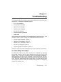
Chapter 6 Troubleshooting
6.1
6.2
6.3
6.4
6.5
6.6
6.6.1
6.7
6.7.1
6.7.2
6.7.3
Error Skip Procedure . . . . . . . . . . . . . . . . . . . . . . .
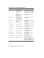
Printer Status Messages . . . . . . . . . . . . . . . . . . . .
Operator Call Messages . . . . . . . . . . . . . . . . . . . . .
Software Error Messages . . . . . . . . . . . . . . . . . . . .
Service Call Messages . . . . . . . . . . . . . . . . . . . . . .
Common Operating Problems . . . . . . . . . . . . . . . .
Incorrect Printing Mode . . . . . . . . . . . . . . . . . . .
Paper Jams . . . . . . . . . . . . . . . . . . . . . . . . . . . . . .
Paper Jam Areas 1, 6, and 7 . . . . . . . . . . . . . . .
Paper Jam Areas 2, 3, 4, and 6 . . . . . . . . . . . . .
Paper Jam Area 5 (Duplex Printing Mode Only)
.
.
.
.
.
.
.
.
.
.
.
.
.
.
.
.
.
.
.
.
.
.
.
.
.
.
.
.
.
.
.
.
.
.
.
.
.
.
.
.
.
.
.
.
.
.
.
.
.
.
.
.
.
.
.
v
6.7.4
Paper Jam Area 8 (Duplex Printing Only) . . . . . . . . . . . . . 6–26
Chapter 7 Maintenance
7.1
7.1.1
7.1.2
7.1.3
7.2
7.3
7.4
Cleaning the Printer . . . . . . . . . . . . . . . . .
Cleaning the Internal Surfaces . . . . . . .
Cleaning the Primary Corona Wire . . . .
Cleaning the Transfer Corona Wires and
Extending EP-S Cartridge Life . . . . . . . . .
Replacing the EP-S Cartridge . . . . . . . . . .
Replacing the Ozone Filter . . . . . . . . . . . . .
..............
..............
..............
Discharging Pins
..............
..............
..............
7–1
7–2
7–7
7–14
7–20
7–21
7–39
Digital Equipment Corporation Services . . . . . . . . . . . . . . . .
8–1
Chapter 8 Service
8.1
Appendix A DEClaser Printer Quick Reference Guide
A.1
A.2
A.3
A.4
A.5
Positioning Controls . . . . .
Margins and Spacing . . . .
Set/Reset Modes . . . . . . . .
Fonts and Character Sets
Miscellaneous . . . . . . . . . .
.
.
.
.
.
.
.
.
.
.
.
.
.
.
.
.
.
.
.
.
.
.
.
.
.
.
.
.
.
.
.
.
.
.
.
.
.
.
.
.
.
.
.
.
.
.
.
.
.
.
.
.
.
.
.
.
.
.
.
.
.
.
.
.
.
.
.
.
.
.
.
.
.
.
.
.
.
.
.
.
.
.
.
.
.
.
.
.
.
.
.
.
.
.
.
.
.
.
.
.
.
.
.
.
.
.
.
.
.
.
.
.
.
.
.
.
.
.
.
.
.
.
.
.
.
.
.
.
.
.
. A–2
. A–5
. A–10
. A–11
. A–16
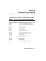
Appendix B Accessories and Supplies
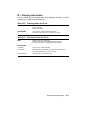
B.1
Ordering Information . . . . . . . . . . . . . . . . . . . . . . . . . . . . . . .
B–3
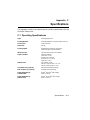
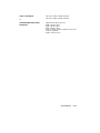
Appendix C Specifications
C.1
C.2
C.3
vi
Operating Specifications . . . . . . . . . . . . . . . . . . . . . . . . . . . . .
Serial Interface Specifications . . . . . . . . . . . . . . . . . . . . . . . .
Parallel Interface Specifications . . . . . . . . . . . . . . . . . . . . . . .
C–1
C–4
C–7
Appendix D LN03 Compatibility
D.1
D.2
D.3
General Differences . . . . . . . . . . . . . . . . . . . . . . . . . . . . . . . .
Printable Area Compatibility . . . . . . . . . . . . . . . . . . . . . . . . .
Protocol Compatibility . . . . . . . . . . . . . . . . . . . . . . . . . . . . . .
D–1
D–2
D–2
Glossary
Index
Figures
1
1–1
1–2
1–3
1–4
1–5
1–6
2–1
2–2
2–3
2–4
2–5
2–6
2–7
3–1
4–1
4–2
4–3
4–4
4–5
4–6
4–7
5–1
CDRH Label . . . . . . . . . . . . . . . . . . .
Components: Front/Right-Side View
Components: Rear/Left-Side View . .
Components: Rear Output Tray . . . .
Components: Inside the Printer . . . .
Operating Space: Top View . . . . . . .
Operating Space: Side View . . . . . . .
Printout Selector . . . . . . . . . . . . . . .
Printout Selections . . . . . . . . . . . . . .
Duplex Paper Path . . . . . . . . . . . . . .
Engine Test Print . . . . . . . . . . . . . . .
Test Print A . . . . . . . . . . . . . . . . . . .
Test Print B . . . . . . . . . . . . . . . . . . .
Font List . . . . . . . . . . . . . . . . . . . . .
Control Panel . . . . . . . . . . . . . . . . . .
Sample of a Menu . . . . . . . . . . . . . .
Menu Display . . . . . . . . . . . . . . . . . .
Operating Memory . . . . . . . . . . . . . .
Operational Flow Chart . . . . . . . . . .
Test Print A Verification . . . . . . . . . .
Offset Positioning . . . . . . . . . . . . . . .
Offset Printout Samples . . . . . . . . . .
Unacceptable Labels . . . . . . . . . . . .
.
.
.
.
.
.
.
.
.
.
.
.
.
.
.
.
.
.
.
.
.
.
.
.
.
.
.
.
.
.
.
.
.
.
.
.
.
.
.
.
.
.
.
.
.
.
.
.
.
.
.
.
.
.
.
.
.
.
.
.
.
.
.
.
.
.
.
.
.
.
.
.
.
.
.
.
.
.
.
.
.
.
.
.
.
.
.
.
.
.
.
.
.
.
.
.
.
.
.
.
.
.
.
.
.
.
.
.
.
.
.
.
.
.
.
.
.
.
.
.
.
.
.
.
.
.
.
.
.
.
.
.
.
.
.
.
.
.
.
.
.
.
.
.
.
.
.
.
.
.
.
.
.
.
.
.
.
.
.
.
.
.
.
.
.
.
.
.
.
.
.
.
.
.
.
.
.
.
.
.
.
.
.
.
.
.
.
.
.
.
.
.
.
.
.
.
.
.
.
.
.
.
.
.
.
.
.
.
.
.
.
.
.
.
.
.
.
.
.
.
.
.
.
.
.
.
.
.
.
.
.
.
.
.
.
.
.
.
.
.
.
.
.
.
.
.
.
.
.
.
.
.
.
.
.
.
.
.
.
.
.
.
.
.
.
.
.
.
.
.
.
.
.
.
.
.
.
.
.
.
.
.
.
.
.
.
.
.
.
.
.
.
.
.
.
.
.
.
.
.
.
.
.
.
.
.
.
.
.
.
.
.
.
.
.
.
.
.
.
.
.
.
.
.
.
.
.
.
.
.
.
.
.
.
.
.
.
.
.
.
.
.
.
.
.
.
.
.
.
.
.
.
.
.
.
.
.
.
.
.
.
.
.
.
.
.
.
.
.
.
.
.
.
.
.
.
.
.
.
.
.
.
.
.
.
.
.
.
.
.
.
.
.
.
.
.
.
.
.
.
.
.
.
.
.
.
.
.
.
.
.
.
.
.
.
.
.
.
.
.
.
.
.
.
.
.
.
.
.
.
.
.
.
.
.
.
.
xvii
1–2
1–4
1–6
1–8
1–11
1–11
2–7
2–8
2–11
2–36
2–39
2–43
2–46
3–1
4–1
4–4
4–6
4–10
4–14
4–21
4–22
5–9
vii
6–1
7–1
C–1
C–2
C–3
C–4
C–5
Paper Jam Areas . . . . . . . . . . . . . .
Rocking the EP-S Cartridge . . . . . .
RS232C Pin Assignments . . . . . . . .
Serial Connections to Modem . . . . .
Serial Connections Without Modem
Parallel Pin Assignment . . . . . . . .
Parallel Connections . . . . . . . . . . .
.
.
.
.
.
.
.
.
.
.
.
.
.
.
.
.
.
.
.
.
.
.
.
.
.
.
.
.
.
.
.
.
.
.
.
.
.
.
.
.
.
.
.
.
.
.
.
.
.
.
.
.
.
.
.
.
.
.
.
.
.
.
.
.
.
.
.
.
.
.
.
.
.
.
.
.
.
.
.
.
.
.
.
.
.
.
.
.
.
.
.
.
.
.
.
.
.
.
.
.
.
.
.
.
.
.
.
.
.
.
.
.
.
.
.
.
.
.
.
.
.
.
.
.
.
.
.
.
.
.
.
.
.
. 6–12
. 7–21
. C–4
. C–5
. C–6
. C–9
. C–9
Printer Components: Front/Right-Side View
Printer Components: Rear/Left-Side View . .
Printer Components: Rear Output Tray . . . .
Printer Components: Internal View . . . . . . .
Legal-Size Coding Example . . . . . . . . . . . . .
Test Print A . . . . . . . . . . . . . . . . . . . . . . . . .
Printing Test Print A . . . . . . . . . . . . . . . . . .
Printing Test Print B . . . . . . . . . . . . . . . . . .
Printing the Font List . . . . . . . . . . . . . . . . .
Entering Control Representation Mode . . . .
Resetting the Printer . . . . . . . . . . . . . . . . . .
Control Panel Functions . . . . . . . . . . . . . . .
Keypad Functions: Keypad Mode . . . . . . . . .
Entering Menu Mode . . . . . . . . . . . . . . . . . .
Keypad Functions: Menu Mode . . . . . . . . . .
Recalling Factory Default Values from ROM
Saving Values in NVRAM . . . . . . . . . . . . . .
Saving Values in RAM . . . . . . . . . . . . . . . . .
Changing and Saving Values . . . . . . . . . . . .
Menu Mode Features and Values . . . . . . . . .
FEEDER Menu Features and Values . . . . . .
LAYOUT Menu Features and Values . . . . . .
COPY Menu Features and Values . . . . . . . .
COMMAND Menu Features and Values . . .
INITIAL Menu Features and Values . . . . . .
Device Identification . . . . . . . . . . . . . . . . . .
User Preference Character Set . . . . . . . . . . .
.
.
.
.
.
.
.
.
.
.
.
.
.
.
.
.
.
.
.
.
.
.
.
.
.
.
.
.
.
.
.
.
.
.
.
.
.
.
.
.
.
.
.
.
.
.
.
.
.
.
.
.
.
.
.
.
.
.
.
.
.
.
.
.
.
.
.
.
.
.
.
.
.
.
.
.
.
.
.
.
.
.
.
.
.
.
.
.
.
.
.
.
.
.
.
.
.
.
.
.
.
.
.
.
.
.
.
.
.
.
.
.
.
.
.
.
.
.
.
.
.
.
.
.
.
.
.
.
.
.
.
.
.
.
.
.
.
.
.
.
.
.
.
.
.
.
.
.
.
.
.
.
.
.
.
.
.
.
.
.
.
.
.
.
.
.
.
.
.
.
.
.
.
.
.
.
.
.
.
.
.
.
.
.
.
.
.
.
.
.
.
.
.
.
.
.
.
.
.
.
.
.
.
.
.
.
.
.
.
.
.
.
.
.
.
.
.
.
.
.
.
.
.
.
.
.
.
.
.
.
.
.
.
.
.
.
.
.
.
.
.
.
.
.
.
.
.
.
.
.
.
.
.
.
.
.
.
.
.
.
.
.
.
.
.
.
.
.
.
.
.
.
.
.
.
.
.
.
.
.
.
.
.
.
.
.
.
.
.
.
.
.
.
.
.
.
.
.
.
.
.
.
.
.
.
.
.
.
.
.
.
.
.
.
.
.
.
.
.
.
.
.
.
.
.
.
.
.
.
.
.
.
.
.
.
.
.
.
.
.
.
.
.
.
.
.
.
.
.
.
.
Tables
1–1
1–2
1–3
1–4
2–1
2–2
2–3
2–4
2–5
2–6
2–7
3–1
3–2
4–1
4–2
4–3
4–4
4–5
4–6
4–7
4–8
4–9
4–10
4–11
4–12
4–13
4–14
viii
1–3
1–5
1–7
1–9
2–19
2–40
2–41
2–44
2–47
2–48
2–49
3–2
3–5
4–2
4–3
4–7
4–8
4–9
4–11
4–15
4–19
4–20
4–23
4–23
4–24
4–25
4–26
4–15
4–16
4–17
5–1
5–2
5–3
5–4
6–1
6–2
6–3
6–4
6–5
8–1
A–1
A–2
A–3
A–4
B–1
B–2
B–3
C–1
C–2
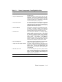
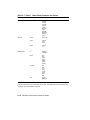
Macro Feature Examples . . . . . . . . . . . . . . . . . . .
INTERFACE Menu Features and Values . . . . . . .
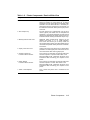
DUPLEX Menu Features and Values . . . . . . . . . .
Cassette Feed Paper Sizes . . . . . . . . . . . . . . . . . .
Paper Specifications . . . . . . . . . . . . . . . . . . . . . . .
Transparency Sizes . . . . . . . . . . . . . . . . . . . . . . .
Transparency Specifications . . . . . . . . . . . . . . . . .
Printer Status Messages . . . . . . . . . . . . . . . . . . .
Operator Call Messages . . . . . . . . . . . . . . . . . . . .
Software Error Messages . . . . . . . . . . . . . . . . . . .
Service Call Messages . . . . . . . . . . . . . . . . . . . . .
Common Operating Problems . . . . . . . . . . . . . . .
Questions to Consider Before You Call . . . . . . . . .
DECVPFS Selective Parameters . . . . . . . . . . . . .
SCS—Select Character Set . . . . . . . . . . . . . . . . .
NRC Fallback Selection . . . . . . . . . . . . . . . . . . . .
Selective Digital Private Parameters . . . . . . . . . .
DEClaser 2200 Printer Accessories and Supplies .
Ordering Within the U.S.A. . . . . . . . . . . . . . . . . .
Ordering Outside the U.S.A. . . . . . . . . . . . . . . . .
Serial Interface Pin Assignment . . . . . . . . . . . . .
Parallel Interface Pin Assignments . . . . . . . . . . .
.
.
.
.
.
.
.
.
.
.
.
.
.
.
.
.
.
.
.
.
.
.
.
.
.
.
.
.
.
.
.
.
.
.
.
.
.
.
.
.
.
.
.
.
.
.
.
.
.
.
.
.
.
.
.
.
.
.
.
.
.
.
.
.
.
.
.
.
.
.
.
.
.
.
.
.
.
.
.
.
.
.
.
.
.
.
.
.
.
.
.
.
.
.
.
.
.
.
.
.
.
.
.
.
.
.
.
.
.
.
.
.
.
.
.
.
.
.
.
.
.
.
.
.
.
.
.
.
.
.
.
.
.
.
.
.
.
.
.
.
.
.
.
.
.
.
.
.
.
.
.
.
.
.
.
.
.
.
.
.
.
.
.
.
.
.
.
.
.
.
.
.
.
.
.
.
.
.
.
.
.
.
.
.
.
.
.
.
.
.
.
.
.
.
.
.
.
.
4–27
4–28
4–31
5–2
5–3
5–8
5–8
6–2
6–3
6–5
6–7
6–8
8–2
A–7
A–14
A–15
A–16
B–1
B–3
B–3
C–4
C–8
ix
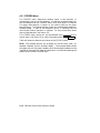
Preface
The DEClaser 2200 printer uses electrophotographic laser technology to
print text and graphics at speeds up to 8 pages/minute with a density of
300 x 300 dots/inch. The printer consists of an engine (print mechanism)
and a controller (formatter) that are driven from host-based software to
provide shared printer access from the Digital network. The printer can
serve as a personal desktop printer or as a shared group printer, and is
designed to print from 5,000 to 12,000 prints per month.
Some of the features of the DEClaser 2200 printer include:
•
Duplex (two-sided) printing capability
•
Two cassette trays with automatic switching capability
•
Capacity for two (optional) external Digital ANSI-compliant font
cartridges
•
Font downline loading capability
•
Support for both serial and parallel interfaces
•
Convenient user maintenance (one replaceable supply cartridge)
•
Ability to print on envelopes
•
Manual feeding capability
The following are some of the options available for the DEClaser 2200
printer:
•
User-installable memory expansion (up to 3 MB)
•
Digital ANSI-compliant font cartridges
•
User-installable PostScript upgrade capability
•
User-installable envelope feeder
•
Envelope cassette
xi
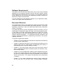
Software Requirements
Some features of the DEClaser 2200 printer may or may not be available
depending on the operating software used by the host computer system
and the application software that you are using. For information about the
printer features you can use with your application program, consult your
application program documentation.
For help choosing the right software package for your application needs,
contact your Digital sales representative.
Document Structure
This guide focuses mainly on the operational aspects of the DEClaser 2200
and explains how to use and maintain the printer hardware. For printer
installation instructions, refer to the DEClaser 2200 Printer Installation
Guide in this binder.
This guide describes the printer components and their functions, such as
loading paper, changing the supply cartridge, and using the operator panel.
It also covers the proper maintenance procedures to keep your printer
operating efficiently, and basic troubleshooting techniques for correcting
common operating problems. The appendices describe accessories and
supplies, operating specifications, programming information, and contain
a glossary of terms.
This guide is organized as follows:
•
Chapter 1, Printer Components, describes the components and features
of the DEClaser 2200 printer.
•
Chapter 2, Operating Information, covers operating procedures such as
powering the printer on, loading paper, and adjusting print density. It
also describes how to manually feed print media.
•
Chapter 3, The Control Panel, covers the use of the printer’s control
panel. It describes operational information about the indicators, keys,
and message display.
•
Chapter 4, Printer Configuration, explains how to configure the printer
so that it can communicate with your computer system. You configure
the printer by selecting features and their associated values from the
various set-up menus. This chapter also describes how to save values
in memory.
•
Chapter 5, Print Media, describes the various printing media that
can be used with the DEClaser 2200, including paper, envelopes,
xii
transparencies, and labels. It also addresses the proper way to store
and handle paper.
•
Chapter 6, Troubleshooting, contains basic testing and troubleshooting
techniques that allow you to correct common operating problems such
as poor printing or paper jams.
•
Chapter 7, Maintenance, explains how to care for and maintain the
printer. It describes how to replace the electrophotographic supply (EPS) cartridge and ozone filter, and how to clean the printer.
•
Chapter 8, Service, explains how to obtain service if the printer needs
repair.
•
Appendix A, DEClaser Printer Quick Reference Guide, lists the
DEClaser escape sequences used to program the printer. It is intended
as a reference for the experienced programmer.
•
Appendix B, Accessories and Supplies, describes the accessories and
supplies available for the DEClaser 2200 printer and explains how to
order them.
•
Appendix C, Specifications, lists the power, environmental, and physical
specifications of the DEClaser 2200 printer.
•
Appendix D, LN03 Compatibility, highlights the major differences
between the LN03 and DEClaser 2200 printers.
•
The glossary contains definitions of printer-related terms.
Ordering Additional Copies of This Documentation Set
You can order additional copies of this documentation set from DECdirect
as described in the ordering information section at the end of this guide.
The ordering number for the documentation is EK–D2200–DK.
The documentation set consists of one of each of the following:
•
DEClaser 2200 Printer Installation Guide
•
DEClaser 2200 Printer Operator’s Guide
•
Spine insert for the binder
•
Three-ring binder
NOTE: You cannot order the installation or operator’s guide individually.
You can only order the documentation set.
xiii
Associated Documents
Several other related manuals are available for use with the DEClaser 2200
printer. You can order these optional manuals from DECdirect as described
in the ordering information section at the end of this guide.
Those optional manuals are:
•
Digital ANSI-Compliant Printing Protocol Level 3 Programming
Reference Manual (AA–PBWGA–TE)
This manual is for application programmers who create software that
produces Digital ANSI-compliant level 3 output. It describes printer
protocol character processing and printer control functions.
•
Digital ANSI-Compliant Printing Protocol Level 3 Programming
Supplement (AA–PBWHA–TE)
Contains device specific information for programmers who create
applications for Digital’s ANSI-compliant level 3 devices. It is also for
programmers who write applications with ANSI output that requires
conversion to the PostScript page description language for printing on
Digital printers.
•
PostScript Translators Reference Manual for ReGIS and Tektronix 4010
/4014 (AA–PBWFA–TE)
This manual is for programmers who need to convert ReGIS or
Tektronix 4010/4014 documents to PostScript for printing on PostScript
printers. The DEClaser 2200 has a PostScript option and can print
Tektronix 4010/4014 and ReGIS files using the Common Print Symbiont
(CPS).
•
Digital Laser Printers Guide to Paper and Other Media
(EK–LASER–GD)
This manual is for general users and contains detailed information
about buying and storing print media (paper, envelopes, labels, and
transparencies) that can be used with Digital laser printers.
xiv
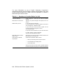
Conventions Used in This Guide
The following terms and conventions are used in this guide:
Convention
Meaning
NOTE
Notes provide important additional information.
CAUTION
Cautions provide information required to prevent damage
to equipment.
WARNING
Warnings provide information to prevent personal injury.
Dash (—)
A statement preceded by a dash describes the result of a
procedural step. For example:
p
Check Mark ( )
1.
Insert the paper cassette by sliding it straight into
the cassette slot.
—
The Alarm indicator shuts off.
—
The display reads 00 READY.
A statement marked by a check mark indicates a special
instruction related to a procedural step. For example:
1.
p
p
Key
To prevent paper jams, do not load too much paper
into the cassette. Leave a small amount of space
between the paper and the maximum height guard.
Make sure the paper lies perfectly flat in the cassette.
A key name is shown enclosed in a box to indicate that
you press that key on the control panel. Key names are
always shown in initial capital letters. For example:
1.
UPPERCASE
Add paper to the cassette by placing it into the left
side first, being sure the paper is inserted below the
paper guide and maximum height guard.
Press
Menu
to access the printer menu selections.
Printer status messages and operator call messages are
shown in uppercase. For example:
—
The display reads 00 READY.
—
The display reads 11 PAPER OUT.
xv
Convention
Meaning
Bold
Items from the scrolling menus appear as they do on the
display (uppercase, lowercase, or initial capital letters)
with the menu item shown in bold type. For example:
1.
Press
—
Menu
to enter Menu Mode.
The menu display reads FONT/FEED LAYOUT.
Safety Information
The DEClaser 2200 printer complies with all United States government
safety regulations applicable to ozone gas emissions and laser beam light
exposure. Read the following information to become familiar with ozone
and laser safety.
Ozone Safety
Ozone is a colorless gas (O3 ) that is a by-product of the electrophotographic
process. The DEClaser printers use an ozone filter to remove the ozone
generated by the printer. The ozone filter is replaced at 100,000 page
intervals. See Appendix B for ordering information.
WARNING: Be sure to replace the ozone filter every 100,000 pages, and never
operate the printer without the ozone filter in place. The filter removes ozone
that could be hazardous to your health.
xvi
Laser Safety
The DEClaser 2200 printer complies with 21 CFR Chapter 1, Subchapter
J, as a Class 1 laser product under the U.S. Department of Health and
Human Services (DHHS) Radiation Performance Standard according to the
Radiation Control for Health and Safety Act of 1968. The printer does not
emit hazardous light since the laser beam is totally enclosed during all
modes of customer operation and maintenance.
WARNING: Use of controls or adjustment procedures other than those
specified in this manual may result in hazardous laser light exposure.
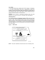
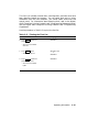
CDRH Regulations
The Center for Devices and Radiological Health (CDRH) of the U.S. Food
and Drug Administration implemented regulations for laser products on
August 2, 1976. These regulations apply to laser products manufactured
beginning August 1, 1976. Compliance is mandatory for products marketed
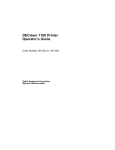
in the United States. The label shown in Figure 1 indicates compliance with
the CDRH regulations and must be attached to laser products marketed in
the United States.
Figure 1: CDRH Label
DANGER -
INVISIBLE LASER RADIATION WHEN OPEN.
AVOID DIRECT EXPOSURE TO BEAM.
ATTENTION VORSICHT -
RAYONNEMENT LASER INVISIBLE SI OUVERT.
DANGEREUX DE REGARDER A L’INTERIEUR.
..
UNSICHTBARE LASERSTRAHLEN WENN GEOFFNET.
NICHT HINEINSEHEN.
750-850nm
5mW
.
Laserstrahl
CAUTION -
INVISIBLE LASER RADIATION WHEN OPEN.
AVOID EXPOSURE TO BEAM.
ATTENTION -
VARO! -
RAYONNEMENT LASER EN CAS
D’OUVERTURE EXPOSITION DANGEREUSE
AU FAISCEAU.
..
.. .. ..
AVATTAESSA
OLET..ALTTINA
NAKYMATTOMALLE
..
..
..
LASERSATEILYLLE ALA KATSO SATEESEEN.
MLO-004945
NOTE: This label is attached to the laser scanner unit inside the printer.
xvii
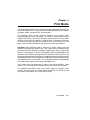
Chapter 1
Printer Components
This chapter describes the components of the DEClaser 2200 printer and
their functions. This chapter also provides information about the operating
space required to perform day-to-day printing operations.
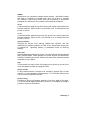
1.1 Functions of the Printer Components
Figure 1–1, Figure 1–2, Figure 1–3, and Figure 1–4 show the printer
components. Table 1–1, Table 1–2, Table 1–3, and Table 1–4 explain the
printer components and their functions.
Printer Components
1–1
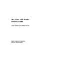
Figure 1–1: Components: Front/Right-Side View
MLO-005110 (Figure 1-1; 14.5 picas)
1–2 DEClaser 2200 Printer Operator’s Guide
Table 1–1: Printer Components: Front/Right-Side View
Component
Function
1. Top Output Tray
Printed sheets are automatically collated and stacked
(facedown) here.
2. Top Cover Release Button
Pressing this button unlocks the top cover so it can
be opened. The top cover is opened to perform certain
printer funtions such as adding a new EP-S1 cartridge
or clearing a paper jam. See Section 2.3 for more
information about opening the top cover.
3. Carrying Grip Plate
The carrying grip plates are located on the right and
left sides of the printer. These plates are grooved
to provide a nonslip surface when you are lifting the
printer. Always place your hands under the carrying
grip plates when lifting the printer.
4. Test Print Button
This button is used to print the Engine Test Print.
The button is recessed. To depress it use a ballpoint
pen or similar instrument. See Section 2.12 for more
information about printing the Engine Test Print.
5. Control Panel
The control panel consists of a message display,
indicator lights, and a keypad.
The control
panel provides information on printer status and
can be used to perform certain printer functions
such as resetting the printer or configuring the
printer menus.
See Chapter 3 for additional
information about using the control panel while
printing. Chapter 5 has information about using the
control panel to change the various printer menus.
6. Font Cartridge Slots
These two slots accept the optional font and emulation
program cartridges available for the printer.
7. Upper and Lower Paper Cassettes
The paper cassettes automatically feed paper to the
printer. Each cassette can hold approximately 200
sheets of 20 lb. (75 g/m2 basis weight) paper. See
Section 2.8 for more information about loading paper
in the cassettes.
8. Manual Feed Guide
The manual feed guide is part of the paper cassette
cover. The feed guide allows you to manually feed
paper, envelopes, transparencies, and labels into the
printer. For more information about feeding print
media manually, see Section 2.9.
1 EP-S
stands for electrophotographic supply.
Printer Components
1–3
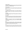
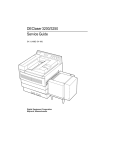
Figure 1–2: Components: Rear/Left-Side View
MLO-005111 (Figure 1-2; 12.5 picas)
1–4 DEClaser 2200 Printer Operator’s Guide
Table 1–2: Printer Components: Rear/Left-Side View
Component
Function
1. Power Switch
Powers the printer on or off. Pressing ‘‘ | ’’ turns
power on; pressing ‘‘O’’ turns power off. To ensure
that data is not lost, always be sure the display reads
00 READY and the Data indicator is off before you
power off the printer. See Section 2.1 and Section 2.2
for additional information about powering the printer
on and off.
2. Rear Output Tray
The rear output tray is selected when you are using
certain types of print media such as transparencies
and labels. It can also be used when you want printed
output to be stacked faceup. Refer to Section 2.6.2 for
information about choosing the different output trays.
3. Memory Board Access Cover
Additional RAM (random-access memory) can be
added to the printer in 1, 2, or 3 MB capacities.
This access cover allows you to easily install the
extra memory board. Refer to the documentation that
comes with the optional memory board for installation
instructions.
4. Paper Jam Access Cover
Opening this access cover allows you to remove paper
jammed in the lower paper path. See Section 6.7 for
more information about clearing paper jams.
5. Parallel (Centronics)
Interface Cable Connector
This connector is used when the interface cable from
the host computer is a parallel cable. Refer to the
DEClaser 2200 Printer Installation Guide for more
information about connecting your computer to the
printer.
6. Serial (RS232)
Interface Cable Connector
This connector is used when the interface cable from
the host computer is a serial cable. Refer to the
DEClaser 2200 Printer Installation Guide for more
information about connecting your computer to the
printer.
7. Power Cord Receptacle
This is where the power cord is connected to the
printer.
Printer Components
1–5
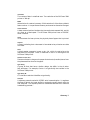
Figure 1–3: Components: Rear Output Tray
MLO-005112 (Figure 1-3; 15.5 picas)
1–6 DEClaser 2200 Printer Operator’s Guide
Table 1–3: Printer Components: Rear Output Tray
Component
Function
8. Extension Tray
Must be extended when printing documents faceup.
See Section 2.6.2 for information about using the
extension tray.
9. Paper Jam Clearance Lever
Lifting this lever allows you to access paper jams in
the rear output tray area. See Section 6.7 for more
information about clearing paper jams.
10. Printout Selector
Selects the rear output tray for faceup documents, or
the top output tray for facedown documents when the
printer is in simplex mode. The duplex position is
used when the printer is in duplex mode and delivers
paper facedown to the top output tray.
NOTE: The printer ‘‘beeps’’ if you try to select duplex
mode and the printout selector is not set to the duplex
position. The printout selector must be set to the
duplex position to print in duplex mode.
11. Paper Support Guide
This guide is raised during printing in duplex mode
(Section 2.7). The guide supports the paper as it
moves over the rear output tray during the reversing
cycle.
Printer Components
1–7
Figure 1–4: Components: Inside the Printer
MLO-005113 (Figure 1-4; 30.5 picas)
1–8 DEClaser 2200 Printer Operator’s Guide
Table 1–4: Printer Components: Internal View
Component
Function
1. Print Density Dial
Has a range of 1–9 to adjust the print density.
Selecting the lower numbers results in heavier or
darker print density. For most printing applications
the dial can be set to 7. See Section 2.11 for additional
information about setting the print density.
2. Cleaning Brush
The (green) cleaning brush has two cleaning surfaces:
The brush end, which is used to clean the discharging
pins on the transfer corona assembly; and the fabric
end, which is used to clean the primary corona wire
in the EP-S cartridge. See Chapter 7 for more
information about using the cleaning brush.
3. Fixing Assembly
The fixing assembly consists of a heat roller, a
pressure roller, and a roller cleaner. Toner is bonded
to the paper as it passes between the heat and
pressure rollers. The roller cleaner removes excess
toner that may accumulate on the heat roller. The
roller cleaner is replaced each time a new EP-S
cartridge is installed. Each EP-S cartridge comes
with replacement instructions, or you can refer to
Section 7.3 for more information about replacing the
roller cleaner.
4. EP-S Cartridge
The EP-S cartridge contains a photo-sensitive drum,
the primary charge corona wire, a drum cleaning
blade, toner, and a toner application roller. When
the 16 TONER LOW message is displayed, it could
mean that the toner is not being distributed evenly.
Rock the cartridge to redistribute the toner (see
Section 7.3).
If the 16 TONER LOW message
continues to be displayed after you rock the cartridge,
it means the EP-S cartridge has run out of toner and
you should replace it (see Section 7.3).
5. Ozone Filter
Removes ozone generated by the printer. The ozone
filter is replaced every 100,000 pages. The page count
is shown on Test Print A (see Section 2.13). See
Section 7.4 for replacement instructions.
WARNING: Do not operate the printer without the
ozone filter in place. The filter removes ozone that
could be hazardous to your health.
Printer Components
1–9
Table 1–4 (Cont.): Printer Components: Internal View
Component
Function
6. Transfer Corona Assembly
Contains a corona wire that places a negative charge
on the paper as it passes over the wire. This negative
charge attracts the (positively charged) toner from
the photo-sensitive drum in the EP-S cartridge to
the paper. Keep the transfer corona wire clean
at all times to ensure optimum print quality. See
Section 7.1.3 for information about cleaning the
transfer corona wire.
7. Paper Transfer Guide
Ensures that paper is properly routed from the
cassette to the transfer corona assembly. You can
also open the paper transfer guide to access paper
jams that occur in that area. Lift the green handle to
remove the jammed paper.
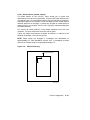
1.2 Required Operating Space
Always allow ample space around the printer to perform day-to-day printing
operations. Figure 1–5 shows the minimum amount of space required to
perform these operations. See the DEClaser 2200 Printer Installation Guide
for additional information about location requirements and environmental
conditions.
1–10 DEClaser 2200 Printer Operator’s Guide
Figure 1–5: Operating Space: Top View
MLO-005115 (Figure 1-5; 15 picas)
Figure 1–6: Operating Space: Side View
MLO-005114 (Figure 1-6; 12 picas)
Printer Components
1–11
Chapter 2
Operating Information
This chapter provides the operating information necessary to perform dayto-day printer operations. It covers typical tasks such as adding paper,
selecting an output tray, or powering the printer on and off. This chapter
also covers manual feed operation for all print media.
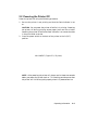
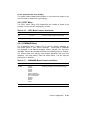
2.1 Powering the Printer On
Power the printer on using the following procedure.
1. Press the power switch on the back of the printer to the | (ON) position.
MLO-005116 (Figure 2-1; 16 picas)
You should observe the following when you power on the printer:
— All control panel indicators light for a moment.
— The Ready indicator flashes and the display reads
02 WARMING UP (assuming that the printer has cooled below
operating temperature before it is powered on).
Operating Information
2–1
— The Online and Ready indicators remain on and the display reads
00 READY
DEC.
NOTE: The display reads 00 READY
DEC only if you are using
Digital’s ANSI-compliant printing protocol, which is the factory
default setting. If you are using an optional protocol such as
PostScript or CaPSL, the display shows the protocol being used.
For instance, if you are using PostScript protocol, the display reads
00 READY
PS. Since several protocols can be used with the
DEClaser 2200 printer, the remainder of this manual shows the
message as 00 READY.
If the printer does not power on correctly, refer to Chapter 6 for
troubleshooting information.
2–2 DEClaser 2200 Printer Operator’s Guide
2.2 Powering the Printer Off
Power the printer off using the following procedure.
1. Be sure the printer is not printing and that the Data indicator is not
on.
CAUTION: Do not power the printer off while it is printing. Powering
the printer off during printing causes paper jams and loss of data.
Powering the printer off while the Data indicator is on causes the data
in the print buffer to be lost.
2. Press the power switch on the back of the printer to the O (OFF)
position.
MLO-005117 (Figure 2-2; 15 picas)
NOTE: After powering the printer off, always wait at least two seconds
before you power the printer back on. This waiting period ensures that
the printer will initialize (cycle) properly when it is powered back on.
Operating Information
2–3
2.3 Opening the Top Cover
Open the top cover using the following procedure.
1. Press the release button forward and then down.
— The top cover releases and opens slightly.
MLO-005118 (Figure 2-3; 15.5 picas)
2–4 DEClaser 2200 Printer Operator’s Guide
2. Lift the top cover open to the halfway position (about 30°) or to the
upright position (about 90°).
MLO-005119 (Figure 2-4; 12 picas)
p
p
The halfway position is intended for:
•
Replacing the EP-S cartridge
•
Adjusting the print density dial
The upright position is intended for:
•
Replacing the fixing roller cleaner
•
Replacing the ozone filter
•
Clearing paper jams
•
Cleaning the inside of the printer
Operating Information
2–5
2.4 Closing the Top Cover
Close the top cover using the following procedure.
1. Gently lower the cover and push down on the hand grip until the cover
latches securely in place.
MLO-005120 (Figure 2-5; 16 picas)
2–6 DEClaser 2200 Printer Operator’s Guide
2.5 Printout Selector
The printout selector (located on the rear paper tray) allows you to choose
the output tray for the type of jobs you are printing. You can place the
selector in one of two positions as shown in Figure 2–1.
Figure 2–1: Printout Selector
MLO-005121 (Figure 2-6; 16 picas)
The duplex/facedown position (top output tray) and the faceup position
(rear output tray), can be used when the printer is in simplex mode (see
Section 2.6.2 and Section 2.6.1).
The duplex/facedown position has a secondary function that serves as the
duplex print position during printing in duplex mode. In duplex mode, the
rear output tray is used as a paper reversing area before the paper is fed
back into the printer. The printout selector must be in the duplex/facedown
position to print in duplex mode, and paper is always delivered to the top
output tray (see Section 2.7).
Operating Information
2–7
2.6 Printout Selection in Simplex Mode
Printed paper is delivered and stacked either facedown or faceup depending
on the printout position selected (Figure 2–2). When faceup is selected,
printed paper is delivered faceup to the rear output tray. Although the
rear output tray can be used to stack paper faceup from a cassette, it
is used primarily to stack manually fed envelopes, transparencies, labels
and heavier weight (thicker) papers. See Section 2.9 for information about
manually feeding print media.
When duplex/facedown is selected, printed paper is delivered facedown to
the top output tray. Your print job is collated in the correct page order when
it is delivered to the top output tray.
NOTE: You cannot select the printout delivery (faceup or duplex/facedown)
through a command from the host computer; positioning the printout selector
is the only way to select the printout delivery for all modes of operation.
Figure 2–2: Printout Selections
MLO-005122 (Figure 2-7; 19 picas)
CAUTION: Do not try to change the printout selector while the printer is
printing. Changing the printout selector during printing causes paper jams.
2–8 DEClaser 2200 Printer Operator’s Guide
2.6.1 Selecting Facedown Printout (Top Output Tray)
Use the following procedure to select the top output tray for facedown
printing.
1. Set the printout selector to the duplex/facedown position.
MLO-005123 (Figure 2-8; 16 picas)
2. Fold in the extension tray.
MLO-005124 (Figure 2-9; 16 picas)
Operating Information
2–9
2.6.2 Selecting Faceup Printouts (Rear Output Tray)
Use the following procedure to select the rear output tray for faceup
printing.
1. Set the printout selector to the faceup position.
MLO-005126 (Figure 2-10; 16 picas)
2. Fold out the extension tray.
MLO-005125 (Figure 2-11; 16 picas)
2–10 DEClaser 2200 Printer Operator’s Guide
2.7 Printing in Duplex Mode
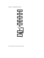
Figure 2–3 shows the paper path used during printing in duplex mode. The
duplex mode can be selected using a command from the host computer, or
by using Duplex on the control panel.
NOTE: Although you can select duplex mode using a command from the
host computer, you cannot select the printout delivery (faceup or duplex/
facedown) from the host; positioning the printout selector is the only way to
select the correct printout delivery.
Figure 2–3: Duplex Paper Path
MLO-005127 (Figure 2-12; 15.5 picas)
The following restrictions apply during printing in duplex mode:
•
You cannot feed envelopes.
•
You cannot feed paper manually.
Operating Information
2–11
2.7.1 Duplex Printing Printer Setup
Use the following procedure to set the printer up for duplex printing.
1. Set the printout selector to the duplex print position.
MLO-005128 (Figure 2-13; 16 picas)
2. Lift the paper support guide up from under the rear output tray.
MLO-005129 (Figure 2-14; 16 picas)
2–12 DEClaser 2200 Printer Operator’s Guide
3. Press
On Line
to place the printer off line.
— The On Line indicator shuts off.
4. Press
Duplex
to place the printer in duplex mode.
— The Duplex indicator lights.
NOTE: If the printer ‘‘beeps’’ and the Duplex indicator does not light,
the printer is probably in the manual feed mode. Check to see that the
Feeder Menu is not set to the manual feed mode (see Section 4.5.1).
5. Press
On Line
to place the printer back on line.
— The On Line indicator lights.
Operating Information
2–13
2.8 Loading Paper
The printer comes standard with either A4-size (210 mm x 297 mm) or
letter-size (8 ½" x 11") paper cassettes, depending on the country it is
shipped to. Optional paper cassettes are available that can accommodate
the following print media:
•
Legal-size paper (8 ½" x 14")
•
Executive-size paper (7 ¼" x 10 ½")
•
Envelopes
For ordering information about optional paper cassettes, see Appendix B.
Each paper cassette can hold approximately 200 sheets of 75 g/m2 basis
weight (20 lb.) paper. Each cassette incorporates a convenient paper feed
guide on its cover that can be used to manually feed paper, envelopes,
transparencies, and labels. See Section 2.9 for information about feeding
print media manually.
Here are some general guidelines about the paper used in the printer.
•
Use only high-quality paper such as the papers listed in Appendix B.
•
Avoid using any paper that is creased, folded, punched, clipped, stapled,
or damaged.
•
To prevent paper curl (a curved bend in the paper), stack the paper on
a flat surface for storage.
•
Prevent changes to the moisture content of the paper by storing it
properly and rewrapping unused portions. Do not store paper directly
on the floor.
Complete specifications for print media are in Chapter 5. For more detailed
information, consult the Digital Laser Printers Guide to Paper and Other
Media (see Appendix B for ordering information).
2–14 DEClaser 2200 Printer Operator’s Guide
2.8.1 Adding Paper to the Cassettes
Add paper to the cassettes using the following procedure.
1. Check to see that the printer is not printing and that the display reads
00 READY before you remove the paper cassette. If the printer has run
out of paper, the display reads 11 PAPER OUT or 17 U<- ->L FEED.
CAUTION: Do not remove the paper cassette while the printer is
printing. Removing the paper cassette during printing can damage the
printer.
2. Remove the empty cassette by pulling it straight out from the printer.
— The display reads 11 PAPER OUT or 17 U<- ->L FEED.
— The Alarm indicator lights.
MLO-005130 (Figure 2-15; 16 picas)
Operating Information
2–15
3. Remove the cassette cover by lifting it off.
MLO-004838 (Figure 2-16; 12.5 picas)
4. Insert paper into the left side of the cassette first, being sure it is
inserted below the paper guide and maximum height guard.
p
p
To prevent paper jams, do not load too much paper into the cassette.
Leave a small amount of space between the paper and the maximum
height guard.
Make sure the paper lies perfectly flat in the cassette.
MLO-004839 (Figure 2-17; 13 picas)
2–16 DEClaser 2200 Printer Operator’s Guide
5. Replace the cover on the cassette.
MLO-004840 (Figure 2-18; 13.5 picas)
6. Insert the paper cassette into the printer.
— The Alarm indicator shuts off.
— The display reads 00 READY.
MLO-005131 (Figure 2-19; 13.5 picas)
Operating Information
2–17
2.9 Feeding Media Manually
The paper feed guide on the cover of the cassette enables you to manually
feed paper, labels, transparencies, and envelopes into the printer. The
paper feed guide also allows you to print on odd-size paper that cannot
be used in the cassette.
NOTE: You cannot feed media manually when the printer is in the duplex
mode of operation.
Although labels and transparencies are usually fed manually, high-quality
labels and transparencies, such as those sold through DECdirect, can also
be fed automatically from the cassette. Check the media specifications in
Chapter 5 for additional information about labels and transparencies.
Not all media can be fed automatically from the cassette. You must feed
the following print media into the printer manually:
•
Nonstandard-sized papers from 100 mm x 190 mm (3.9" x 7 ½") to 216
mm x 356 mm (8 ½" x 14") that do not fit in the cassette).
•
Thicker papers whose basis weight is from 84 g/m2 to 135 g/m2 (22 lb.
to 36 lb.)
•
Envelopes (unless you are using the special envelope cassette)
You can invoke manual feed operation in three ways:
•
Using the Feeder Select key on the control panel.
•
Selecting the Manual value in the Feeder Menu.
•
Sending a command from the host computer.
When feeding paper manually, you need to tell the printer the paper size
you are using so that printing occurs in the proper area on the page. For
A4 and letter-size paper you can set the paper (size) feature in the INITIAL
Menu (Table 4–12). The paper feature sets up the printing coordinates for
manual feed operation according to the value selected: either A4 or Letter.
This allows the printer to print within the correct boundaries on the sheet
of paper.
For paper sizes other than A4 or letter, you must use commands from the
host computer that tell the printer the paper size you are using. These
commands tell the printer where to print on the page. An example of this
would be printing on legal-size paper. Since the printer does not recognize
the larger legal-size paper, you must send it the proper commands (escape
sequences) to print correctly on the page. These commands should precede
the data in the file to be printed.
2–18 DEClaser 2200 Printer Operator’s Guide
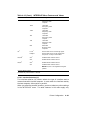
The following command line contains instructions to print on legal-size
paper in manual feed mode. This example is set up to print a file on an
8 ½" x 14" sheet of paper in portrait mode using manual feed. Table 2–1
describes each escape sequence in the example.
<ESC>[7I <ESC>[99;2;2500;4200 { <ESC>[8J <ESC>[99!v
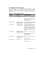
Table 2–1: Legal-Size Coding Example
Escape Sequence
Name of Command
Description
<ESC>[7I
SSU (Size Select Unit)
Units can be pixels, decipoints, or centipoints. This
example uses pixels.
<ESC>[99;2;2500;4200 {
DECSS (Set Sheet Size)
Defines manual feed input
and the width (2500 pixels
= 8 ½") and length (4200
pixels = 14") of the paper.
<ESC>[8J
PFS (Page Format Select)
Selects portrait mode of printing and sets the margins for
the larger size paper.
<ESC>[99!v
DECASFC
(Automatic Sheet Feeder
Control)
Selects the manual feed
mode of operation.
NOTE: Manual feed mode
can also be selected from the
FEEDER Menu, or from the
control panel using
Feeder Select.
See Appendix A for additional programming information. For detailed
information about sending commands from the host computer, consult
the Digital ANSI-Compliant Printing Protocol Level 3 Programming
Reference Manual and the Digital ANSI-Compliant Printing Protocol Level
3 Programming Supplement.
Section 2.9.1 describes how to feed media using Feeder Select on the control
panel to invoke the manual feed mode. See Chapter 4 for information
about setting the manual feed value from the FEEDER menu.
Operating Information
2–19
2.9.1 Manually Feeding Paper, Labels, and Transparencies
Use the following procedure to manually feed paper, labels, and
transparencies. Refer to Chapter 5 for the specifications required for print
media. Be sure the printer is set up to print on the media size you are
using — either through the paper (size) feature in the INITIAL Menu, or
by using commands from the host computer — before feeding media (see
Section 2.9).
NOTE: You can use the rear output tray or the top output tray when
manually feeding paper. You must use the rear output tray when feeding
labels or transparencies to prevent excessive curl.
1. Set the printout selector to the faceup position.
MLO-005126 (Figure 2-20; 16 picas)
2–20 DEClaser 2200 Printer Operator’s Guide
2. Fold out the extension tray.
MLO-005125 (Figure 2-21; 15.5 picas)
3. Press
On Line
to place the printer off line.
— The On Line indicator shuts off.
4. Press
Feeder Select
until the display reads FEEDER = Manual.
— After about three seconds the display will read 00 READY.
— The manual feed mode selection is now stored in operating memory.
5. Press
On Line
to place the printer back on line.
— The On Line indicator lights.
6. Send data from the host computer to the printer.
— The Data indicator lights and the display reads PF FEED xxx
(where xxx = paper size).
Operating Information
2–21
7. Adjust the manual feed guides to accept the width of the paper.
MLO-005132 (Figure 2-22; 15.5 picas)
2–22 DEClaser 2200 Printer Operator’s Guide
8. Insert a single sheet of paper, labels, or a transparency into the printer
until it stops.
— The paper is automatically fed into the printer.
— The printed paper is sent to the rear output tray.
CAUTION: Remove transparencies from the rear output tray as each one
is printed. This prevents them from sticking together.
MLO-005133 (Figure 2-23; 15.5 picas)
Operating Information
2–23
9. Wait until PF FEED xxx is displayed and repeat step 8.
p
p
Continue feeding paper until the Data indicator light shuts off and
the display reads 00 READY.
If you want to continue feeding paper manually after the display
reads 00 READY, go to step 6. If you have finished feeding paper
manually, go to step 10.
10. Press
On Line
to place the printer off line.
— The On Line indicator shuts off.
11. Press Feeder Select until the paper feed mode you want to use is displayed
(FEEDER = Lower, FEEDER = Upper, or FEEDER = Auto).
— After about three seconds the display will read 00 READY.
— The cassette feed mode selection is now stored in operating
memory.
12. Press
On Line
to place the printer back on line.
— The On Line indicator lights.
2–24 DEClaser 2200 Printer Operator’s Guide
13. Set the printout selector to the duplex/facedown position.
MLO-005128 (Figure 2-24; 16 picas)
14. Fold in the extension tray.
MLO-005125 (Figure 2-25; 16 picas)
Operating Information
2–25
2.10 Feeding Envelopes Manually
Envelopes have the same setup requirements as all other media that are fed
manually (see Section 2.9). Since you need to print addresses in a particular
area on envelopes, you must give the printer the proper print coordinates
to print the addresses. Normally the setup requirements for printing
envelopes are defined by the application program you are using. Consult
your application program documentation for details about its envelope
printing feature.
If your application program does not have an envelope printing feature,
you need to set up your address files using commands (escape sequences)
that instruct the printer to print in the right location on the envelope.
Section 2.9 contains an example of using escape sequences to print in
a certain area on the page. Appendix A contains a listing of DEClaser
2200 printer commands and programming information for the experienced
programmer. For detailed programming information to set up your
address files, see the Digital ANSI-Compliant Printing Protocol Level 3
Programming Reference Manual and the Digital ANSI-Compliant Printing
Protocol Level 3 Programming Supplement.
2.10.1 Feeding Envelopes
You should observe some special cautions before feeding envelopes into the
printer. Make the following checks before you manually feed envelopes:
•
The sealing flap should run along the length of the envelope, not at the
leading or trailing edges.
•
Be sure the sealing flap is folded properly with none of the glue exposed.
•
The leading and trailing edges should not be more than two layers thick.
•
The envelope should be folded without any wrinkles or creases.
Specifications for printing envelopes are listed in Section 5.2.
2–26 DEClaser 2200 Printer Operator’s Guide
1. Set the printout selector to the faceup position.
MLO-005126 (Figure 2-26; 16 picas)
2. Fold out the extension tray.
MLO-005125 (Figure 2-27; 16 picas)
Operating Information
2–27
3. Press
On Line
to place the printer off line.
— The On Line indicator shuts off.
4. Press
Feeder Select
until the display reads FEEDER = Manual.
— After about three seconds the display will read 00 READY.
— The manual feed mode selection is now stored in operating memory.
5. Press
On Line
to place the printer back on line.
— The On Line indicator lights.
6. Send data from the host computer to the printer.
— The Data indicator lights and the display reads PF FEED xxx
(where xxx = paper size).
7. Adjust the manual feed guides to accept the width of the envelope.
MLO-005134 (Figure 2-28; 16 picas)
2–28 DEClaser 2200 Printer Operator’s Guide
8. Insert a single envelope into the printer until the envelope stops.
— The envelope is automatically fed into the printer.
— The printed envelope is sent to the rear output tray.
MLO-005135 (Figure 2-29; 16 picas)
Operating Information
2–29
9. Wait until PF FEED xxx is displayed and insert another envelope.
10. Continue feeding envelopes until the Data indicator light shuts off and
the display reads 00 READY.
p
If you want to continue to manually feed envelopes after the display
reads 00 READY, go to step 6. If you have finished feeding
envelopes, go to step 11.
NOTE: If the background of a printed envelope is fogged lightly with
toner, you can reset the print density dial to a lower number to correct
the fogging problem. See Section 2.11 for additional information about
adjusting the print density dial.
11. Press
On Line
to place the printer off line.
— The On Line indicator shuts off.
12. Press Feeder Select until the feed mode you want is displayed (FEEDER =
Lower, FEEDER = Upper, or FEEDER = Auto).
— After about three seconds the display will read 00 READY.
— The cassette feed mode selection is now stored in operating
memory.
13. Press
On Line
to place the printer back on line.
— The On Line indicator lights.
2–30 DEClaser 2200 Printer Operator’s Guide
14. Fold in the extension tray.
MLO-005124 (Figure 2-30; 16 picas)
15. Set the printout selector to the duplex/facedown position.
MLO-005128 (Figure 2-31; 16 picas)
Operating Information
2–31
2.11 Adjusting the Print Density
Print density is the term used to describe the relative thickness of the line
used to print characters. The thickness of a line is known as the line weight.
The print density adjustment controls the amount of toner applied to the
paper to make the line weight thinner or thicker.
You can significantly extend the life of an Electrophotographic Supply
(EP-S) cartridge by setting the print density adjustment dial to the highest
possible number (lightest setting) that gives you acceptable print quality.
For most applications a print density setting of 7 can be used to produce
high-quality print, and extend the life of the cartridge.
NOTE: The EP-S cartridge life can be up to 4,000 A4 or letter-size pages.
This specification is based on 4% toner coverage with the print density set
at 7.
You can check the line weight thickness by printing the Engine Test Print
after performing the adjustment (see Section 2.12).
Use the following procedure to adjust print density.
1. Press the release button forward and then down.
— The top cover releases and opens slightly.
MLO-005118 (Figure 2-32; 15.5 picas)
2–32 DEClaser 2200 Printer Operator’s Guide
2. Lift the top cover open to the halfway position.
MLO-004893 (Figure 2-33; 14.5 picas)
3. Rotate the print density adjustment dial so that the desired density
number is opposite the index triangle.
p
p
p
Numbers on the dial are displayed in increments of 2.
Number 1 is the darkest setting; number 9 is the lightest setting.
Although the printer is shipped with the dial set to number 5, you
can typically obtain acceptable print quality, prolong the cartridge
life, and reduce toner consumption by setting the dial to 7.
MLO-004849 (Figure 2-34; 16 picas)
Operating Information
2–33
4. Close the top cover by gently lowering the cover and pushing down on
the hand grip until the cover latches securely in place.
MLO-005120 (Figure 2-35; 16 picas)
2–34 DEClaser 2200 Printer Operator’s Guide
2.12 Printing the Engine Test Print
The Engine Test Print (Figure 2–4) is used to check the printer’s paper
feed mechanism for proper operation, and to check toner dispersion and
line weight.
The area between the lines on the Engine Test Print should be free of excess
toner or smudges, and the lines should print cleanly across the entire page
with no faded areas. If the print quality is poor, see Section 6.6 for help to
correct the problem.
If the Engine Test Print will not print, there may be a problem with the
paper feed mechanism. Refer to Section 6.6 for help to correct the problem.
If you cannot correct the problem, call the Customer Services group to repair
the printer (see Chapter 8 for service information).
You can check line weight by looking at the thickness of the line after
performing a print density adjustment (Section 2.11).
Operating Information
2–35
Figure 2–4: Engine Test Print
MLO-004525 (Figure 2-36; 36 picas)
2–36 DEClaser 2200 Printer Operator’s Guide
1. Check to be sure the printer has stopped printing and the message
display reads 00 READY.
2. Press the test button on the right side of the printer with a ballpoint
pen.
— The printer enters the offline state.
— The Alarm indicator lights while the page is printing.
— The display reads 15 ENGINE TEST while the page is printing.
— The printer remains in the offline state and the display reads
00 READY.
MLO-004894 (Figure 2-37; 19 picas)
3. Press
On Line
to place the printer back on line.
Operating Information
2–37
2.13 Printing Test Print A
Test Print A (Figure 2–5) lists the current printer settings, along with
information such as total page count and the amount of free memory
available.
2–38 DEClaser 2200 Printer Operator’s Guide
Figure 2–5: Test Print A
MLO-004895 (Figure 2-38; 36 picas)
Operating Information
2–39
When Test Print A can be printed, it is a nearly certain indication that
the printer is functioning properly. You can print Test Print A to see what
the current printer settings are before making changes in Menu Mode (see
Chapter 4). Table 2–2 describes the items on Test Print A, and Table 2–3
decribes how to print the test print.
Table 2–2: Test Print A
Item
Description
Version
This is the version of firmware the printer is using.
The firmware version number aids the Customer
Services engineer if there is a problem with the
printer.
Total RAM
This is the total amount of random-access memory
available in the printer.
RAM is shown in
kilobytes listing the base amount of RAM plus any
optional RAM (base RAM + optional RAM).
Font Card
Lists the name of installed font cartridges and
their location (left or right font cartridge slot).
Page Count
Indicates the total number of pages printed to
date.
Free RAM
Indicates the total amount of RAM available.
This memory space can be used to downline load
fonts from the host computer, be reserved as
bitmap pages, or used to support options such as
PostScript.
Current Settings
Shows all of the setup menus and the current
values in operational memory. Each menu also
shows what kind of memory the values can be
stored in: RAM only, NVRAM only, or in either
type of memory (RAM + NVRAM).
See Table 4–7 and Section 4.5 for a complete listing
and description of all the menu features.
2–40 DEClaser 2200 Printer Operator’s Guide
Use the procedure in Table 2–3 to print a copy of Test Print A.
Table 2–3: Printing Test Print A
Operation
Display Reads
1. Press On Line to place the
printer off line.
00 READY
— The On Line indicator
shuts off.
2. Press
Test/Font
once.
05 TEST PRINT A
#
— Test Print A prints.
00 READY
3. Press On Line to place the
printer back on line.
00 READY
— The On Line indicator
lights.
Operating Information
2–41
2.14 Printing Test Print B
Test Print B (Figure 2–6) contains sample printouts of the primary and
secondary character sets that can be examined for print quality.
2–42 DEClaser 2200 Printer Operator’s Guide
Figure 2–6: Test Print B
MLO-004852 (Figure 2-39; 36 picas)
Operating Information
2–43
Test Print B is printed continuously (until instructed to stop) so it can also
be used to test paper feed, paper delivery, and other mechanical functions
of the printer.
Use the procedure in Table 2–4 to print a copy of Test Print B.
Table 2–4: Printing Test Print B
Operation
Display Reads
1. Press On Line to place the
printer off line.
00 READY
— The On Line indicator
shuts off.
2. Press and hold down Test/Font
for about three seconds.
01 TEST PRINT B
— The test page prints
continuously.
3. Press Test/Font to stop
printing Test Print B.
NOTE: You can also press
On Line to stop printing
Test Print B.
4. Press On Line to place the
printer back on line.
04 TEST STOP
#
00 READY
00 READY
— The On Line indicator
lights.
2–44 DEClaser 2200 Printer Operator’s Guide
2.15 Printing the Font List
Figure 2–7 shows the Font List, which contains a listing of all the available
character sets in the printer, along with a sample of the available fonts.
Operating Information
2–45
Figure 2–7: Font List
MLO-004853 (Figure 2-40; 36 picas)
2–46 DEClaser 2200 Printer Operator’s Guide
The Font List includes internal fonts, cartridge fonts, and fonts that have
been downline loaded into memory. You can select fonts only by using
commands from the host computer; you cannot select them from the
control panel. For information about selecting fonts, refer to the Digital
ANSI-Compliant Printing Protocol Level 3 Programming Reference Manual
and the Digital ANSI-Compliant Printing Protocol Level 3 Programming
Supplement.
Use the procedure in Table 2–5 to print the font list.
Table 2–5: Printing the Font List
Operation
Display Reads
1. Press On Line to place the
printer off line.
00 READY
— The On Line indicator
shuts off.
2. Press
Test/Font
twice.
06 FONT LIST
#
— The font list prints.
00 READY
3. Press On Line to place the
printer back on line.
00 READY
— The On Line indicator
lights.
Operating Information
2–47
2.16 Using Control Representation Mode
The Control Representation Mode is used to print out unprocessed data
or commands sent from the host computer. This procedure is sometimes
referred to as ‘‘dumping.’’ The printing of unprocessed data (in the form
of characters and symbols) is convenient for debugging programs. If a
specified character is undefined, a hexadecimal representation is printed.
This section explains how to print the character listing. For additional
information about Control Representation Mode, consult the Digital ANSICompliant Printing Protocol Level 3 Programming Reference Manual.
NOTE: If the file does not fill the page buffer completely, the remaining
data can be printed by pressing On Line to place the printer off line, and then
pressing Form Feed to print the partial page.
2.16.1 Entering Control Representation Mode
Use the procedure in Table 2–6 to place the printer in Control
Representation Mode.
Table 2–6: Entering Control Representation Mode
Operation
Display Reads
1. Press On Line to place the
printer off line.
00 READY
— The On Line indicator
shuts off.
2. Press and hold
Reset for about
10 seconds.
03 RESET
#
03 DUMP
#
03 RESET
#
00 READY
DUMP
The printer is now in Control Representation Mode and ready to accept
data or commands from the printer. To exit Control Representation Mode,
perform a soft reset (see Section 2.17).
2–48 DEClaser 2200 Printer Operator’s Guide
2.17 Resetting the Printer
There are two methods of resetting the printer:
•
You can perform a hard reset by powering the printer off and then
back on.
•
You can perform a soft reset by pressing
Reset
.
The primary reasons for a soft reset of the printer are to exit Control
Representation Mode and to clear data in the page buffer.
Use the procedure in Table 2–7 to perform a soft reset.
Table 2–7: Resetting the Printer
Operation
Display Reads
1. Press On Line to place the
printer off line.
00 READY
— The On Line indicator
shuts off.
2. Press and hold
Reset for about
three seconds.
03 RESET
3. Press On Line to place the
printer back on line.
00 READY
#
00 READY
— The On Line indicator
lights.
Operating Information
2–49
Chapter 3
The Control Panel
The control panel consists of a liquid crystal display (LCD), indicator lights,
and a keypad. The keypad allows you to perform certain printer functions
such as printing test pages or configuring the printer menus. This chapter
explains the features and uses of the control panel.
The layout of the control panel is shown in the following figure and
described in Table 3–1.
Figure 3–1: Control Panel
MLO-004896 (Figure 3-1; 11 picas)
The Control Panel
3–1
Table 3–1: Control Panel Functions
Item
Function
Keypad
Some keys on the keypad perform a dual function
depending on whether the printer is in Keypad
Mode or Menu Mode. In Keypad Mode, the keys
perform the primary function labeled on the key
such as Test/Font or Feeder Select. When the
printer is in Menu Mode, the keys perform the
secondary function labeled with the gray colored
symbols and text, such as / or . .
NOTE: All keys and related functions (with the
exception of On Line ) work only when the printer
is off line. This is true whether the printer is in
Keypad Mode or Menu Mode.
See Section 3.1 for information about using the
keypad in Keypad Mode.
See Section 4.1 for information about using the
keypad in Menu Mode.
On Line indicator (green)
Works in conjunction with On Line to indicate
when the printer is on line or off line (see On Line
in Table 3–2).
On: The printer is on line and controlled by the
host computer. The host computer can send data
to print and commands to control the printer.
Off: The printer is off line and cannot receive any
data or commands from the host computer. It can
only be controlled using the keys on the control
panel.
Form Feed indicator (green)
Works in conjunction with Form Feed to indicate
when data in the print buffer is being printed
or when the command to print is canceled (see
Form Feed in Table 3–2).
On: Data in the print buffer is being printed.
Off: Data is not being printed.
Flashing: Command to print is canceled.
Duplex indicator (green)
Indicates whether the printer is set to print in
duplex mode (two-sided printing) or simplex mode
(one-sided printing).
On: Prints in duplex mode.
Off: Prints in simplex mode.
3–2 DEClaser 2200 Printer Operator’s Guide
Table 3–1 (Cont.): Control Panel Functions
Item
Function
Data indicator (green)
Indicates the status of the data sent to the printer.
On: Data is being printed
buffer. If the indicator is
not printing, it means the
printed. Press Form Feed to
or is still in the print
on and the printer is
last page needs to be
print the last page.
Off: All data has been printed.
Flashing: Data is being received from the host
computer.
NOTE: Data is lost if you power off or reset the
printer when the Data indicator is on or is flashing.
Alarm indicator (orange)
Indicates that an error condition exists.
A
‘‘beep’’ sounds when the printer first senses an
alarm condition. The message display works in
conjunction with the Alarm indicator by showing
the type of error condition.
For example: 12 PRINTER OPEN
The Alarm indicator shuts off when the error
condition is cleared.
See Chapter 6 for information on correcting
printer errors.
Ready indicator (green)
Indicates when the printer is ready to print.
On: The printer is ready to print.
Off: The printer is powered off or an error
condition exists (the Alarm indicator is on).
Flashing: The printer is warming up.
Message display
The message display shows the current status of
the printer.
For example: 00 READY
When the printer is in Menu Mode, the display
shows the selected menu, feature, or value.
For example: COMMAND INITIAL
The Control Panel
3–3
Table 3–1 (Cont.): Control Panel Functions
Item
Function
Paper jam indicators (orange)
These indicators show the area where paper is
jammed: in the upper paper path, the lower
paper path, or in the rear output tray area. See
Section 6.7 for information about clearing paper
jams.
Paper feed indicators (green)
These light to indicate the currently selected paper
feed cassette or envelope feeder. They are:
•
Envelope feeder (optional)
•
Upper paper cassette
•
Lower paper cassette
NOTE: If none of the paper feed indicators are on,
it indicates that the printer is in manual feed mode.
3.1 Using the Keypad in Keypad Mode
Some keys on the keypad perform a dual function, depending on whether
the printer is in Keypad Mode or Menu Mode. In Keypad Mode, the keys
perform the primary function labeled on the key, such as Test/Font or
Manual Feed. Table 3–2 shows the keypad functions in Keypad Mode.
NOTE: With the exception of On Line , all keys operate only when the printer
is off line. A ‘‘beep’’ sounds if any of these keys are pressed when the printer
is on line.
3.1.1 Entering Keypad Mode
Enter Keypad Mode using the following procedure.
1. Press
On Line
to place the printer off line.
— The On Line indicator shuts off.
— The keypad is now in Keypad Mode.
3–4 DEClaser 2200 Printer Operator’s Guide
Table 3–2: Keypad Functions: Keypad Mode
Key
On Line
Function
Pressing On Line alternates the printer between the online
mode and offline mode. The mode is indicated by the green
light on the key.
On: The printer is on line and controlled by the host
computer. The host computer can send data to print and
commands to control the printer.
Off: The printer is off line and cannot receive any data
or commands from the host computer. It can only be
controlled using the keys on the control panel.
Form Feed
Form Feed works in conjunction with the Data indicator. If
the Data indicator is on after a file stops printing, it means
there is still data in the print buffer. Pressing Form Feed
prints the remaining pages in the print buffer.
When you press Form Feed , the indicator on the key lights
to show that the data is being printed. If you press
Form Feed again while the data is printing, it stops printing
the remaining pages and the indicator flashes until the
current page exits the printer. Once the page exits the
printer, the indicator light remains off. Form Feed can be
pressed again to resume printing.
Error Skip
The DEClaser 2200 printer alerts you to certain error
conditions by stopping the printer and displaying the type
of error on the control panel. When this happens you
may elect to note the problem and then continue printing
by pressing Error Skip . Pressing Error Skip bypasses these
errors so that printing continues. After you press Error Skip
the printer remains off line. You must press On Line to
place the printer back on line and continue printing.
Some errors can repeat, such as communications errors
or print formatting errors when the printer is receiving
additional communication data. When this happens you
may need to repeat the Error Skip procedure several times.
Refer to Chapter 6 for additional information about errors
and corrective actions.
The Control Panel
3–5
Table 3–2 (Cont.): Keypad Functions: Keypad Mode
Key
Test/Font
Reset
Function
Test/Font
performs several functions in Keypad Mode:
•
Pressing the key once prints Test Print A (see
Section 2.13).
•
Pressing and holding the key down for at least three
seconds prints Test Print B (see Section 2.14).
•
Pressing the key twice prints the Font List (see
Section 2.15).
Pressing Reset performs a soft reset by clearing the data
in the print buffer and returning the printer to the ready
state. The printer operates with the settings currently
stored in RAM, which are loaded into operating memory
when a reset is performed.
You can also use Reset to exit Control Representation
Mode (see Section 2.16).
Menu
Places the printer in Menu Mode and displays the first
menu: FONT/FEED LAYOUT.
Refer to Section 4.1 for more information about Menu
Mode.
Duplex
Pressing Duplex alternates between simplex mode (onesided printing) and duplex mode (two-sided printing). If
the printer ‘‘beeps’’ when you press Duplex , check to be
sure that the printout selector is in the duplex position (see
Table 1–2), and that the printer is not set in the manual
feed mode of operation (see Section 4.5.1).
3–6 DEClaser 2200 Printer Operator’s Guide
Table 3–2 (Cont.): Keypad Functions: Keypad Mode
Key
Feeder Select
Function
Pressing Feeder Select changes the paper feed selection.
There are five paper feed modes:
•
Auto feed (either upper or lower cassette)
•
Upper cassette
•
Lower cassette
•
Manual feed
•
Option (available only when the optional envelope
feeder is installed)
See Section 4.5.1 for additional information about the
feeder selections. See Section 2.9 for more information
about feeding print media manually.
NOTE: The manual feed and option feed modes are not
selectable when the printer is in duplex mode.
3.2 Using the Keypad in Menu Mode
You configure the printer by selecting certain parameters (features and
values) while in Menu Mode. You select these parameters using keypad
keys that function differently when the printer is in Menu Mode. Chapter 4
covers printer configuration and explains the use of the keypad when in
Menu Mode (see Section 4.1).
The Control Panel
3–7
Chapter 4
Printer Configuration
This chapter describes how to configure the printer by selecting operating
parameters that can be stored in the printer’s memory. These operating
parameters are known as features and values. By selecting the correct
operating parameters, you ensure that the printer can communicate
properly with the host computer and application software.
You configure the DEClaser 2200 printer by selecting an appropriate set
of values from a group of printer setup menus. You make these selections
while the printer is in Menu Mode. Once values are selected you can save
them in the appropriate type of memory. Saving features in the proper type
of memory allows you to retain most printer values so that the printer has
to be configured only once. Figure 4–1 shows a sample menu from Test
Print A.
Figure 4–1: Sample of a Menu
MLO-004856 (Figure 4-1; 11.5 picas)
Printer Configuration
4–1
You can access some menu features by using commands from the host
computer; you can select others only from the control panel. This chapter
describes how to select features using the control panel. For information
about selecting features using commands from the host computer, see
the Digital ANSI-Compliant Printing Protocol Level 3 Programming
Reference Manual and the Digital ANSI-Compliant Printing Protocol Level
3 Programming Supplement.
NOTE: The interface, message, and page offset features can be configured
only from the control panel.
4.1 Entering Menu Mode
You configure the printer by selecting certain parameters (features and
values) while in Menu Mode. When the printer is in Menu Mode, the keys
labeled with gray text and symbols function to select parameters from the
menu. Table 4–1 shows how to enter Menu Mode.
NOTE: With the exception of
is off line.
On Line
, all keys operate only when the printer
Table 4–1: Entering Menu Mode
Operation
Display Reads
1. Press On Line to place the
printer off line.
00 READY
— The On Line indicator
shuts off.
2. Press Menu to place the
printer in Menu Mode.
FONT/FEED LAYOUT
— The printer is now in Menu
Mode and the keys
labeled with gray text
and symbols operate.
4–2 DEClaser 2200 Printer Operator’s Guide
4.1.1 Using the Keypad in Menu Mode
Table 4–2 describes the function of the Menu Mode keys. After reading the
description of the Menu Mode keys, you may want to try using the keys to
better understand their funtionality. See Section 4.4.1 for an example that
uses the Menu Mode keys to configure the printer.
Table 4–2: Keypad Functions: Menu Mode
Key
Function
.
Performs two functions:
/
•
Scrolls the menus and features to the right
•
Increases numeric values
Performs two functions:
•
Scrolls the menus and features to the left
•
Decreases numeric values
4
Returns the printer to the previous level of operation
r Enter
Performs three functions:
On Line
•
Advances to the next (lower) menu level
•
Invokes the ROM, RAM, and NVRAM functions
•
Invokes the selected value
Exits Menu Mode and returns printer operation
back on line
Printer Configuration
4–3
4.2 Reading the Display in Menu Mode
Printer status and operator call messages are shown on the display in
uppercase lettering, preceded by a numerical code. Examples of such
messages are 00 READY or 11 PAPER OUT. Menu Mode messages
are displayed differently to distinguish differences between the menu
selections, feature selections, and value selections.
NOTE: The menu names on the message display are written to accommodate
the protocols available on the DEClaser 2200 printer (ANSI, PostScript, or
CaPSL). Depending on the protocol being used, the menu names that appear
on the message display may not read exactly as they do on Test Print A. For
example, if you are using Digital’s ANSI-Compliant Printing Protocol, the
first menu listed on Test Print A is the FEEDER menu, but on the message
display it is printed as the FONT/FEED menu.
4.2.1 Displaying Menu and Feature Selections
Menu and feature selections are scrolled to the left or right, and are shown
on the display in groups of 16 characters. This means that in addition to
the menu or feature you have selected, other characters are displayed from
the next menu or feature. Think of the menu and feature selections as
being placed on a scrolling band separated only by a space. The display
shows a group of 16 characters from the band and denotes the selection by
displaying it first with a cursor below the first letter. See the examples in
Figure 4–2.
Figure 4–2: Menu Display
.. LOAD< -ROM
.
FONT/FEED
LAYOUT
COPY/OVERLAY
16 Characters
Press
to scroll to the left
LOAD< -ROM
FONT/FEED
Press
LAYOUT
to scroll to the right
COPY/OVERLAY
MLO-004919
4–4 DEClaser 2200 Printer Operator’s Guide
This manual shows items from the scrolling menus and features as they
are displayed (uppercase, lowercase, or initial capitals) with the selected
item shown in bold type for clarification. For example:
FONT FEED LAYOUT or offsetX offsetY
4.2.2 Displaying Menu Values
Menu values are scrolled to the right and left using . and / and are
displayed with the associated feature, for example:
i/f
RS232C
When you scroll through the values, the currently selected value is always
displayed first and is denoted by an equal sign (=) between the feature and
value, for example:
i/f
=RS232C
4.3 Printer Configuration Memory
Printer configuration uses four types of memory: an operating memory that
contains the currently selected values, and three storage memories in which
values are stored or saved. These memories are known as ROM (readonly memory), RAM (random-access memory), and NVRAM (nonvolatile
random-access memory).
NOTE: All four types of printer configuration memory are separate and
distinct from the Free RAM listed on Test Print A. Configuration memory
can be accessed only from the menus to set up the operational parameters of
the printer.
You can save new values temporarily in RAM, but they are cleared when
the printer is powered off. You can also save new values in NVRAM so that
they are not cleared if the printer is reset or powered off. ROM contains
the factory default values that can be recalled into the operating memory.
Some values can be saved only in RAM or only in NVRAM, while other
values can be saved in either type of memory. For a listing of the types of
memory in which values can be saved, see Table 4–7.
Printer Configuration
4–5
4.3.1 Operating Memory
The printer operates using the currently selected values contained in
operating memory. When the printer is powered on, it loads the values
stored in NVRAM into operating memory. When you select new values
(through escape sequences or from the control panel), they are placed in
operating memory and become part of the printer settings that are currently
in use. Figure 4–3 shows the operational flow between the different types
of memory.
Figure 4–3: Operating Memory
ROM
Load<-ROM
NVRAM
Save->NVRAM
RAM
Power On
Printer
Save->RAM
Reset
Operating Memory
(Contains Current Printer Settings)
Commands
(Host Computer)
ROM
NVRAM
RAM
Menu Operations
(Control Panel)
Not Cleared at Power-Off (Cannot Be Changed)
Not Cleared at Power-Off (Can Be Changed)
Cleared at Power-Off (Can Be Changed)
MLO-004947
4–6 DEClaser 2200 Printer Operator’s Guide
4.3.2 ROM (Read-Only Memory)
Read-only memory contains default values that are set at the factory. They
are called default values because they are stored in ROM and cannot be
changed. You can load these default values into operating memory while
in Menu Mode using the procedure shown in Table 4–3.
NOTE: Default values loaded from ROM are temporary values, and are
affected if the printer receives a reset command or is powered off. If you
want to retain the default values, you must save them in NVRAM (see
Section 4.3.3).
Table 4–3: Recalling Factory Default Values from ROM
Operation
Display Reads
1. Press On Line to place the
printer off line.
00 READY
— The On Line indicator
shuts off.
2. Press Menu to place the
printer in Menu Mode.
FONT/FEED LAYOUT
3. Press / once.
LOAD<–ROM FONT/F
4. Press r Enter to
load the default
values from ROM.
OK (momentarily)
5. Press On Line to place
the printer on line.
00 READY
#
LOAD<–ROM FONT/F
— The On Line indicator
lights.
Printer Configuration
4–7
4.3.3 NVRAM (Nonvolatile Random-Access Memory)
The printer can communicate with many systems using the factory default
settings in ROM, but you may have to change values to accommodate your
particular application or host computer. NVRAM allows those changes to
be saved in a nonvolatile memory so that they are available each time you
power on the printer. In nonvolatile memory the selected values are not
cleared when the printer is powered off or reset. Selections are saved in
NVRAM until you change them. To save values in NVRAM while in Menu
Mode, use the procedure shown in Table 4–4.
Table 4–4: Saving Values in NVRAM
Operation
Display Reads
1. Press On Line to place the
printer off line.
00 READY
— The On Line indicator
shuts off.
2. Press Menu to place the
printer in Menu Mode.
FONT/FEED LAYOUT
3. Press / twice.
SAVE–>NVRAM LOAD
4. Press r Enter
to save the values
in NVRAM.
OK (momentarily)
5. Press On Line to place
the printer on line.
00 READY
#
SAVE–>NVRAM LOAD
— The On Line indicator
lights.
4–8 DEClaser 2200 Printer Operator’s Guide
4.3.4 RAM (Random-Access Memory)
Random-access memory is a temporary memory area that stores selected
values until the printer is powered off. It is useful to store features in RAM
when you need to change settings for specific print jobs. To save values in
RAM while in Menu Mode, use the procedure in Table 4–5.
Table 4–5: Saving Values in RAM
Operation
Display Reads
1. Press On Line to place the
printer off line.
00 READY
— The On Line indicator
shuts off.
2. Press Menu to place the
printer in Menu Mode.
FONT/FEED LAYOUT
3. Press / three times.
SAVE–>RAM SAVE–>
4. Press r Enter
to save the values
in RAM.
OK (momentarily)
5. Press On Line to place
the printer on line.
00 READY
#
SAVE–>RAM SAVE–>
— The On Line indicator
lights.
4.4 Operational Flow in Menu Mode
Figure 4–4 illustrates the operational flow to select and change values while
in Menu Mode. See Section 4.4.1 for an example of selecting values while
in Menu Mode.
Printer Configuration
4–9
Figure 4–4: Operational Flow Chart
Place the Printer
Off Line
Enter Menu
Mode
Select the
Menu
Select the
Feature
.
Change the
Value Settings
No
Save
Yes
Save Settings
in Memory
Place the
Printer Back
On Line
MLO-004946
4–10 DEClaser 2200 Printer Operator’s Guide
4.4.1 Sample Procedure for Changing and Saving Values
This section contains an example of how to change and save values in Menu
Mode. Use the steps in Table 4–6 to perform the following tasks:
•
Enter Menu Mode
•
Change page offset values of X and Y in the LAYOUT menu
from +0:0 to 010:0
•
Save the new values in NVRAM
•
Exit Menu Mode
Before You Begin
This example assumes that the printer is using the factory default values
in ROM. You will use Test Print A to verify the changes you make. Print a
copy of Test Print A before beginning this example (Section 2.13). Be sure
that all printing has stopped and the display reads 00 READY before you
make any changes.
Table 4–6: Changing and Saving Values
Operation
Display Reads
1. Press On Line to place the
printer off line.
00 READY
— The On Line indicator
shuts off.
2. Press Menu to place the
printer in Menu Mode.
FONT/FEED LAYOUT
3. Press . once to scroll
the display to the
LAYOUT menu.
LAYOUT COPY/OVER
4. Press r Enter to enter
the LAYOUT menu.
offsetX offsetY
5. Press r Enter to select
the offsetX feature.
offsetX =+0.0
Printer Configuration
4–11
Table 4–6 (Cont.): Changing and Saving Values
Operation
Display Reads
6. Press / until the
value equals -10.0.
offsetX -10.0
NOTE: The value decreases
in steps of 0.5.
7. Press r Enter to enter
the new value.
offsetX =-10.0 (momentarily)
#
offsetX offsetY
8. Press . once to scroll
the display to the offsetY feature.
offsetY autoNL o
9. Press r Enter to select
the offsetY feature.
offsetY =+0.0
10. Press / until the
value equals -10.0.
offsetX -10.0
NOTE: The value decreases
in steps of 0.5.
11. Press r Enter to enter
the new value.
offsetY =-10.0 (momentarily)
#
offsetY autoNL o
12. Press 4 to return
to the menu selections.
LAYOUT COPY/OVER
13. Press / three
times to reach the
NVRAM SAVE menu.
SAVE->NVRAM LOAD
14. Press r Enter to save
the offset values in
NVRAM.
OK (momentarily)
#
SAVE–>NVRAM LOAD
4–12 DEClaser 2200 Printer Operator’s Guide
Table 4–6 (Cont.): Changing and Saving Values
Operation
Display Reads
15. Press On Line to exit
Menu Mode.
00 READY
— The On Line indicator
lights.
Verification
To verify that the offset distances have been changed, print a copy of Test
Print A and compare it with the copy made before the changes. Verify the
changes by comparing the new layout of the page and the offset values in
the LAYOUT menu (see Figure 4–5).
Printer Configuration
4–13
Figure 4–5: Test Print A Verification
MLO-004897 (Figure 4-5; 36 picas)
4–14 DEClaser 2200 Printer Operator’s Guide
4.5 Menu Descriptions
This section describes the printer menus, features, and values.
Table 4–7 for a complete listing of all menus and parameters.
See
Table 4–7: Menu Mode Features and Values
Menu
Features
Values
FEEDER
feeder
Upper1
Auto
Manual
Lower
Option4
LAYOUT
offsetX2
-10.0
.
.
.
+0.01
.
.
.
+10.0
offsetY2
-10.0
.
.
.
+0.01
.
.
.
+10.0
autoNL
ON1
OFF
copy
011 –99
COPY
1 Factory
default setting.
be selected using a command from the host. Selectable from the control panel only.
4 Available only when the optional envelope feeder is installed.
2 Cannot
Printer Configuration
4–15
Table 4–7 (Cont.): Menu Mode Features and Values
Menu
Features
Values
COMMAND
message2
English1
Finnish
French
German
Italian
Japan
Norway
Port.
Spanish
Swedish
Danish
Dutch
INITIAL
macro
0001 –099
paint
Partial1
Full
Dual
paper
Letter1
A4
i/f2
RS232C1
CENTRO
baud3
300
600
1200
2400
48001
9600
19200
rsmode3
8S1
8SS
7OS
7ES
7OSS
7ESS
8OS
8ES
dtr3
Fix-H1
Ready-H
INTERFACE
1 Factory
default setting.
be selected using a command from the host. Selectable from the control panel only.
3 Available only when RS232C is selected.
2 Cannot
4–16 DEClaser 2200 Printer Operator’s Guide
Table 4–7 (Cont.): Menu Mode Features and Values
Menu
DUPLEX
1 Factory
Features
Values
xon/xoff3
ON1
OFF
etx/ack3
OFF1
ON
duplex
OFF1
ON
default setting.
only when RS232C is selected.
3 Available
Printer Configuration
4–17
4.5.1 FEEDER Menu
The FEEDER menu determines whether paper is fed manually or
automatically from one of the cassettes. The optional envelope feeder can
also be selected from the FEEDER menu when that option is installed.
The paper feed selection is shown on the control panel by the paper
feed indicators. The lighted indicator shows the selected feed cassette or
envelope feeder. If none of the indicators are on, it indicates that the
manual feed mode of operation is selected. For more information about
manual feed operation, see Section 2.9.
The FEEDER menu values can also be selected using Feeder Select on the
control panel. See Table 3–2 for more information about using Feeder Select .
Table 4–8 shows the features and values of the FEEDER menu.
NOTE: Two envelope options are available for the DEClaser 2200: an
envelope ‘‘cassette’’ and an envelope ‘‘feeder.’’ The envelope feeder shares
the upper slot with the paper cassette, while the envelope cassette must be
installed in the upper slot. Keep this distinction in mind when selecting the
proper value from the FEEDER menu.
4–18 DEClaser 2200 Printer Operator’s Guide
Table 4–8: FEEDER Menu Features and Values
Feature
Values
Description
feeder
Upper1
Selects the upper paper cassette to automatically
feed paper into the printer.
NOTE: You must select the Upper value when
using the optional envelope ‘‘cassette’’ because the
envelope cassette can only be installed in the
upper cassette slot of the printer.
Auto
Feeds from one of the cassettes until it runs out
of paper, and then automatically switches over to
the second cassette to continue printing. You can
load paper into the empty cassette while printing
from the second cassette. This feature allows
you to print continuously for larger printing jobs.
The same size paper cassettes must be used
when printing in the Auto feed mode.
Manual
Selects the manual feed mode of operation. You
must feed paper one sheet at a time when in the
manual feed mode.
NOTE: The Manual value cannot be selected if
the printer is in duplex mode.
1 Factory
Lower
Selects the lower paper cassette to automatically
feed paper into the printer.
Option2
Selects the optional envelope ‘‘feeder’’ to automatically feed envelopes into the printer.
default setting.
only when the optional envelope feeder is installed.
2 Available
Printer Configuration
4–19
4.5.2 LAYOUT Menu
The features of the LAYOUT menu shown in Table 4–9 allow you to make
adjustments to the print position (the distances from the edges of the paper
where printing begins) and to set the new line so that print wraps when it
reaches the right margin.
Table 4–9: LAYOUT Menu Features and Values
Feature
Values
Description
offsetX
-10.0
.
.
.
+0.01
.
.
.
+10.0
Determines the offset distance from the right
and left sides of the page. An offset of 10.0 is
approximately 1.1".
offsetY
-10.0
.
.
.
+0.01
.
.
.
+10.0
Determines the offset distance from the top
and bottom of the page. An offset of 10.0 is
approximately 1.1".
autoNL
ON1
When the print position reaches the right
margin, it wraps to the left margin of the next
line.
OFF
When the print position reaches the right
margin, it does not move to the next line until
the printer receives a carriage return (CR) or
line feed (LF) command from the host computer.
Data beyond the right margin is lost until the
carriage return or line feed command is received.
1 Factory
default setting.
4–20 DEClaser 2200 Printer Operator’s Guide
4.5.2.1 Offset Position (offsetX, offsetY)
The offset feature of the LAYOUT menu allows you to make fine
adjustments to the printing coordinates. Since the DEClaser 2200 printer
is a page printer, it is not possible to adjust the print position by manually
shifting the position of the page. Do not use offset to move normal data to
different positions on the page. It should only be used as a mechanism to
center the print on the page. Test Print B is typically used when adjusting
the offset positions.
You cannot set offset positions using escape sequences from the host
computer. You must select them from the control panel.
Figure 4–6 shows the directions of offsetX and offsetY in relation to the
direction that paper is fed into the printer.
NOTE: Offset values are changed in increments and decrements of
approximately 0.1" from the default value of +0.0". For example, an offset
value of +5.0 moves the print origin approximately 0.5".
Figure 4–6: Offset Positioning
Feeding Direction
+X
.
+Y
MLO-004944
Printer Configuration
4–21
Figure 4–7 shows sample printouts of Test Print B that use different offset
values.
Figure 4–7: Offset Printout Samples
MLO-004898 (Figure 4-7; 22 picas)
4–22 DEClaser 2200 Printer Operator’s Guide
4.5.2.2 Automatic New Line (autoNL)
The autoNL feature determines whether or not the printer wraps to the
next line when it reaches the right margin.
4.5.3 COPY Menu
The COPY menu (Table 4–10) determines the number of copies to be
printed. You can save this setting only in RAM.
Table 4–10: COPY Menu Features and Values
Feature
Values
Description
copy
011 –99
Sets the number of copies to be printed.
1 Factory
default setting.
4.5.4 COMMAND Menu
The COMMAND menu (Table 4–11) is used to display messages on
the control panel in your native language. Three types of messages
are displayed in the desired language: status, operator call, and error
messages. Service call messages and menus are displayed only in English.
You cannot select this setting using escape sequences from the host
computer. You must select it from the control panel. You can save the
setting only in NVRAM.
Table 4–11: COMMAND Menu Features and Values
Feature
Values
Description
message
English1
Finnish
French
German
Italian
Japan (Japanese)
Norway (Norwegian)
Port. (Portuguese)
Spanish
Swedish
Danish
Dutch
Displays messages in the selected language.
1 Factory
default setting.
Printer Configuration
4–23
4.5.5 INITIAL Menu
The INITIAL menu (Table 4–12) combines the macro, paint, and paper size
features. You can save settings from this menu only in NVRAM.
Table 4–12: INITIAL Menu Features and Values
Feature
Values
Description
macro
0001 –099
Assigns the user preference set and device identification
answer (see Section 4.5.5.1).
paint
Partial1
None of the memory is reserved for bitmap pages.
Memory is allocated dynamically.
Full
Directs the printer to allocate memory space for one
full bitmap page (A4 or letter-size). The Full setting
eliminates complex errors but may slow the printer down
if all pages require a full bitmap.
NOTE: This value can be activated only if at least 1 MB
of optional RAM is installed in the printer.
Dual
Directs the printer to allocate memory space for two full
bitmap pages (A4 or letter-size). The Dual setting allows
you to print at a more efficient speed for documents that
require full page bitmaps for all pages. It also allows you
to print duplex pages, for which each side requires a full
page bitmap. The Dual setting requires more memory
space that must be shared with fonts.
NOTE: This value can be activated only if at least 2 MB
of optional RAM is installed in the printer.
paper
1 Factory
Letter1
Specifies letter-size (8 ½" x 11.0") paper for manual feed
operation.
A4
Specifies A4-size (297 mm x 210 mm) paper for manual
feed operation.
default setting.
4–24 DEClaser 2200 Printer Operator’s Guide
4.5.5.1 Macro
The macro feature allows you to select an environment for local
compatibility. It specifies the return response (device identification) when
a Device Attributes (DA) request is received, and assigns the proper User
Preference character set. The macro feature is slightly different from other
menu features because two parameters (device ID and user preference
character set) are added together to determine the macro value. The device
ID and user preference values cannot be selected independently, they must
be added together to form the macro value.
The DEClaser 2200 printer can identify itself as a Digital ANSI-Compliant
Printing Protocol level 3 printer, and therefore can be recognized as such
by symbionts and terminal drivers that conform to Digital ANSI-compliant
architecture. This identification is also compatible with level 2 devices
because all level 2 sequences are also supported. You can also select an
LN03 identification for applications that require the printer to identify itself
as an LN03 printer. For example, the DECmate word processing system
requires an LN03 device identification. The device identification values are
shown in Table 4–13.
Table 4–13: Device Identification
Device ID
Value
Digital ANSI-compliant
level 3 device
001
LN03
10
1 Factory
default setting.
Printer Configuration
4–25
The second parameter of the macro feature allows you to choose
the User Preference character set appropriate for your application or
system. Consult the Digital ANSI-Compliant Printing Protocol Level
3 Programming Reference Manual for more information about the user
preference sets. Table 4–14 lists the User Preference character sets and
their values.
Table 4–14: User Preference Character Set
User Preference
Character Set
Value
DEC Supplemental
01
ISO Latin-1 Supplemental
1
JIS Katakana
2
ISO Latin-Hebrew
Supplemental
3
DEC Latin-Hebrew
Supplemental
4
DEC 7-Bit Hebrew
5
DEC Technical
6
1 Factory
default setting.
4–26 DEClaser 2200 Printer Operator’s Guide
4.5.5.2 Examples Using the Macro Feature
The examples in Table 4–15 demonstrate how to determine the macro
value.
Table 4–15: Macro Feature Examples
Character Set
and Value
Device ID
and Value
Macro Value
Total
JIS Katakana (2)
Level 3 (00)
02
DEC Technical (6)
Level 3 (00)
06
DEC Supplemental (0)
LN03 (10)
10
4.5.5.3 Paint Mode (paint)
The paint mode (paint) feature instructs the printer to reserve memory
space for one or two full bitmap pages, or not to allocate any bitmapped
memory space for page printing. Since printer memory is shared with both
fonts and page drawings, it is usually desirable to let the printer allocate
the memory dynamically, because even full page sixel images often print
in partial paint mode. You should enable the printer to direct the memory
allocation mechanism only in the following situations:
•
If you are receiving error messages about page complexity, for example,
21 COMPLEX DATA.
•
If pages are breaking incorrectly, for example, half the page prints on
one sheet and the second half on the next sheet.
See Table 4–12 for a complete description of the paint mode values.
4.5.5.4 Paper Size (paper)
The paper size (paper) feature determines the printable area on the page. It
is only used in manual feed mode when no other command (escape sequence)
has been received to specify paper size. See Section 2.9 for additional
information about manually feeding media.
Printer Configuration
4–27
4.5.6 INTERFACE Menu
The correct interface connection is necessary for the printer to communicate
properly with the host computer. The DEClaser 2200 printer supports both
parallel and serial interface connections. The interface must match the
type used by the host computer.
You cannot make selections from the INTERFACE menu using commands
from the host computer. All values must be selected from the control panel
and can be saved only in NVRAM. Once you make the selections you should
save them in NVRAM so that they will be activated (loaded into operational
memory) each time the printer is powered on. The INTERFACE menu
features and values are shown in Table 4–16.
Table 4–16: INTERFACE Menu Features and Values
Feature
Values
Description
i/f
RS232C1
Selects the serial interface to communicate with
the host computer. Select this value if your
computer uses a serial interface.
When RS232C is selected you must select values
for all the other features in this menu (baud rate,
rsmode, and so on).
CENTRO
Selects the (CENTRONICS) parallel interface to
communicate with the host computer. Select this
value if your printer uses a parallel interface.
When the parallel interface is selected, all other
features in the interface menu are ignored.
baud2
300
600
1200
2400
48001
9600
19200
Sets the transmit and receive speed the printer
uses to communicate with the host computer.
The printer speed must match the speed used
by the host computer.
rsmode2
8S1
8 data bits
No parity check
1 stop bit
8ES
8 data bits
Even parity check
1 stop bit
1 Factory
default setting.
only when RS232C is selected.
2 Available
4–28 DEClaser 2200 Printer Operator’s Guide
Table 4–16 (Cont.): INTERFACE Menu Features and Values
Feature
dtr2
xon/xoff2
etx/ack2
Values
Description
8OS
8 data bits
Odd parity check
1 stop bit
7ESS
7 data bits
Even parity check
2 stop bits
7OSS
7 data bits
Odd parity check
2 stop bits
7ES
7 data bits
Even parity check
1 stop bit
7OS
7 data bits
Odd parity check
1 stop bit
8SS
8 data bits
No parity check
2 stop bits
Fix-H1
Sets the DTR line to a fixed high signal.
Ready-H
Sets the DTR line to a high signal when
the printer is ready to receive data.
ON1
Enables buffer overflow control.
OFF
Disables buffer overflow control.
OFF1
Disables buffer overflow control.
ON
Enables buffer overflow control.
NOTE: Etx/ack is not supported on Digital
systems.
1 Factory
default setting.
only when RS232C is selected.
2 Available
4.5.6.1 Interface Selection (i/f)
The interface selection (i/f) feature selects the type of interface used to
communicate with the host computer. It must match the interface used by
the host computer, either serial or parallel.
When you select the parallel interface, you do not select any other settings
in the INTERFACE menu. The other features in this menu apply only
Printer Configuration
4–29
to the serial interface and are not displayed when you select the parallel
interface.
When you select the serial interface, you must also select certain other
values in the INTERFACE menu in order to match the features of the host
computer. The additional features are described next.
4.5.6.2 Baud Rate (baud)
The baud rate (baud) feature sets the transmit and receive speed the printer
uses to communicate with the host computer. The printer speed must match
the speed used by the host computer.
4.5.6.3 RS232C Data Format (rsmode)
The RS232C data format (rsmode) feature determines the data format the
printer uses to communicate with the host computer. The first part of the
value (7 or 8) is the number of data bits the printer expects to see in each
character it receives. The second part of the value is the type of parity
(checking) bit the printer looks for in each character. A parity check is a
method used to detect errors when data is sent over a communications line.
Some systems use an odd parity bit to detect errors, while other systems
use an even parity bit. Some systems use no parity bit at all. The third
part of rsmode is the number of stop bits. Some systems use one stop bit,
while other systems require two. The format for the data bits, parity bit,
and stop bits must match the format of the host computer in order for the
printer and the host to communicate.
4.5.6.4 Data Terminal Ready (dtr)
The data terminal ready (dtr) feature uses hardware to regulate the flow
of data to the input buffer of the printer. Regulation is accomplished by
toggling a signal on the DTR line of the serial port when the printer is ready
to receive data. This is sometimes referred to as hardware handshaking
protocol.
For Digital systems, the dtr feature should always be set to the fixed high
value. When the DTR signal is fixed high (Fix-H) it indicates to the system
that the printer is ‘‘present.’’
4.5.6.5 Buffer Control (xon/xoff)
The buffer control (xon/xoff) feature uses software to regulate the flow of
data to the input buffer of the printer. It is sometimes referred to as
software handshaking protocol, a method the printer and the host computer
use to exchange on/off signals. These signals prevent the input buffer from
overflowing with data. If the input buffer becomes full and handshaking is
not enabled, the overflowing data will be lost. Xon/xoff must be enabled in
systems that use this software handshaking protocol to prevent the loss of
data.
4–30 DEClaser 2200 Printer Operator’s Guide
4.5.6.6 End of Text/Acknowledge (etx/ack)
The end of text/acknowledge (etx/ack) feature is used with another type
of handshaking protocol on some systems to prevent data overflow. The
etx/ack feature also uses software to regulate the flow of data to the input
buffer by exchanging signals with the host computer. It is recommended
that this feature be enabled by systems that support etx/ack to prevent the
loss of data.
NOTE: The etx/ack feature is not supported on Digital systems. Use xon/
xoff if you have a Digital system.
4.5.7 DUPLEX Menu
The DUPLEX menu determines whether paper is printed on one or two
sides. The duplex printing mode can be selected under software control from
the host, or by using Duplex on the control panel. Duplex mode is indicated
when the Duplex indicator is on. See Table 3–2 for more information about
using Duplex .
NOTE: Duplex mode cannot be selected if the printer is in the manual feed
mode of operation, or if the printout selector is set to the faceup position.
Table 4–17 shows the features and values of the DUPLEX menu.
Table 4–17: DUPLEX Menu Features and Values
Feature
Values
Description
duplex
OFF1
Selects the simplex mode of operation. Paper is
printed on one side in simplex mode.
ON
Selects the duplex mode of operation. Paper
is printed on two sides in duplex mode and
delivered to the top output tray.
1 Factory
default setting.
Printer Configuration
4–31
Chapter 5
Print Media
This chapter describes the print media that are appropriate for use with the
DEClaser 2200 printer. The types of print media described in this chapter
are paper, labels, transparencies, and envelopes.
The DEClaser 2200 printer produces excellent print quality using
electrophotographic laser technology. The laser printing process differs
greatly from that of a conventional impact printer, and this is why paper
selection is particularly important. Because toner is bonded to the paper
as it passes through the heat and pressure rollers of the fixing unit, the
paper must be able to withstand high amounts of heat and pressure.
CAUTION: When selecting paper or other print media, always print test
samples of the paper you want to use. This is particularly important when
you are printing on chemically treated or coated paper, such as preprinted
forms or colored paper. The inks and pigments used on these papers must
also be able to withstand the high heat and pressure of the fixing unit. Be
sure to consider the heat limitations of transparencies and the glues used on
envelopes and labels. Always select print media according to the instructions
and specifications in this chapter. For a complete listing of recommended
print media and ordering information, see Appendix B.
Print quality can also deteriorate if paper is not stored properly. Read
Section 5.5 in this chapter for complete information about storing paper.
For additional information about print media, consult the Digital Laser
Printers Guide to Paper and Other Media available from DECdirect (see
the ordering information at the end of this guide).
Print Media
5–1
5.1 Paper Specifications
This section contains information on the sizes and specifications of plain
paper that can be used with the DEClaser 2200 printer.
Table 5–1 lists the paper sizes that can be used with the standard and
optional size cassettes for the printer.
Table 5–1: Cassette Feed Paper Sizes
Paper Size
Dimensions
A4
210 mm x 297 mm
Executive
7 ¼" x 10 ½"
Letter
8 ½" x 11"
Legal
8 ½" x 14"
Manual Feed Paper and Envelope Sizes
Manual feed operation can accept all of the paper sizes listed in Table 5–1
as well as the following sizes for paper and envelopes:
Minimum: 100 mm x 190 mm (4" x 7 ½")
Maximum: 216 mm x 356 mm (8 ½" x 14")
Table 5–2 lists paper specifications for the DEClaser 2200 printer.
5–2 DEClaser 2200 Printer Operator’s Guide
Table 5–2: Paper Specifications
Catagory
Specification
Paper weight: cassette feed
60 g/m2 to 80 g/m2 basis weight
(16 lb. to 21 lb.)
Paper weight: manual feed
60 g/m2 to 135 g/m2 basis weight
(16 lb. to 35 lb.)
Thickness
0.075 mm to 0.115 mm
Moisture content
5% to 8%
Smoothness
100–300 Sheffield
Brightness
84% minimum recommended
Heat tolerance
200°C (392°F) for 0.1 second
Electrical resistance
1.0 x 10¹¹ ohm-cm–2.0 x 10¹² ohm-cm
(cubic content)
2.0 x 10¹⁰ ohm-cm–2.0 x 10¹¹ ohm-cm
(surface)
Cotton (rag) content
25% maximum
5.1.1 Special Considerations When Printing on Paper
Because of the way laser printers print and bond toner to the paper, you
must observe some special requirements with certain types of papers.
•
Do not use preprinted papers that do not meet the specifications for
heat tolerance. The ink from some preprinted papers, such as those
with a company letterhead, can cause smearing and in some extreme
cases could damage the printer.
•
Do not use colored papers in which the color is applied as a coating to
the surface.
•
Do not use thermal papers.
•
Prepunched paper is not recommended.
•
Do not use carbon papers.
Print Media
5–3
5.2 Envelope Requirements
Envelopes must meet the same specifications as paper (see Table 5–2). In
addition, the following types of envelopes cannot be used with the printer:
•
Envelopes with sealing flaps that are open
MLO-004859 (Figure 5-1; 14.5 picas)
5–4 DEClaser 2200 Printer Operator’s Guide
•
Envelopes with sealing flaps at the leading and trailing edges
MLO-004860 (Figure 5-2; 14.5 picas)
•
Envelopes with three or more layers of paper at the leading and trailing
edges
MLO-004861 (Figure 5-3; 15 picas)
Print Media
5–5
•
Envelopes that have transparent windows
MLO-004862 (Figure 5-4; 14 picas)
•
Envelopes that have clasps, snaps, or strings
MLO-004863 (Figure 5-5; 14.5 picas)
5–6 DEClaser 2200 Printer Operator’s Guide
5.2.1 Special Considerations When Printing on Envelopes
Observe the following requirements when printing on envelopes:
•
Feed envelopes manually (if you are not using the special envelope
cassette or envelope feeder).
•
The optional envelope feeder cannot be used in the Auto feed mode.
•
Envelopes can be printed only on the front side.
•
Since you need to print addresses in a particular area on envelopes,
you must give the printer the proper print coordinates to print the
addresses. See Section 2.10 for more information about printing on
envelopes.
•
You cannot print in the 15 mm (3/5") border around the envelope.
•
Use the rear output tray (printout selector set for faceup print).
•
Install the optional envelope cassette only into the upper cassette slot.
MLO-004864 (Figure 5-6; 10 picas)
Print Media
5–7
5.3 Transparencies
Table 5–3 and Table 5–4 contain information on the sizes and specifications
of transparencies that can be used with the DEClaser 2200 printer.
Table 5–3: Transparency Sizes
Transparency Size
Dimensions
A4
210 mm x 297 mm
Letter
8 ½" x 11"
Table 5–4: Transparency Specifications
Category
Specification
Transparency weight
60 g/m2 to 135 g/m2 basis weight
(16 lb. to 36 lb.)
Thickness
0.075 mm to 0.115 mm
Moisture content
5% to 8%
Smoothness
100–300 Sheffield
Heat tolerance
200°C (392°F) for 0.1 second
Electrical resistance
1.0 x 10¹¹ ohm-cm–2.0 x 10¹² ohm-cm (cubic content)
2.0 x 10¹⁰ ohm-cm–2.0 x 10¹¹ ohm-cm (surface)
5.3.1 Special Considerations When Printing Transparencies
Observe the following requirements when printing on transparencies:
•
Transparencies are usually fed manually.
If you are feeding
transparencies from a cassette, be sure they are high-quality
transparencies and meet the specifications listed in Table 5–4.
•
Remove transparencies from the rear output tray as each one is printed
to prevent them from sticking to each other.
5–8 DEClaser 2200 Printer Operator’s Guide
5.4 Labels
A label consists of a face sheet, an adhesive sheet, and a carrier sheet.
The face sheet (or printing surface) is usually composed of photocopying
paper and should meet the same specifications for paper as described in
Table 5–2. The carrier sheet and adhesive used for the labels must also be
able to meet the heat tolerance specification of 200°C (392°F) for at least
0.1 second.
CAUTION: Do not expose the adhesive on the labels because it could cause
damage to the printer. An easy way to test for adhesive that may be exposed
is to press a plain piece of paper on top of the sheet of labels. If the paper
sticks to the labels, you should not use those labels.
Figure 5–1 shows the types of labels that are unacceptable.
Figure 5–1: Unacceptable Labels
MLO-004527 (Figure 5-7; 15.5 picas)
Print Media
5–9
5.4.1 Special Considerations When Printing on Labels
Observe the following requirements when printing on labels:
•
Labels are usually fed manually. If you are feeding labels from
a cassette, be sure they are high-quality labels that meet the
specifications listed in Table 5–2.
•
Be sure that the carrier sheet is not exposed.
•
Be sure that no adhesive is exposed.
•
Use the rear output tray.
5–10 DEClaser 2200 Printer Operator’s Guide
5.5 Paper Handling and Storage
Although you may be using paper that meets all specifications, improper
handling and storage may affect the quality of the paper and the
performance of the printer. Improper storage and handling can cause paper
jams, misfeeding, and other printer performance problems.
Follow the recommendations in this section on paper storage and handling
to reduce the possibility of printer jams and misfeeds.
5.5.1 Paper Handling
Observe the following requirements when handling paper:
•
Load the cassette to its proper capacity rather than adding small
amounts at a time. Loading small amounts of paper can cause jams
because of air pockets created between small stacks of paper.
•
When you unwrap a new package of paper, discard the top and bottom
sheets, as they tend to absorb the most humidity from the surrounding
environment.
•
Check to see that the paper is loaded with the correct side up. Some
packages of paper have an arrow on the label that points in the direction
of the top side of the paper. Load paper with this top side up.
If there is no arrow on the label, check the paper for curl. If a small
amount of curl is present, fan the paper in the opposite direction of the
curl to remove as much of the curl as possible.
•
Follow the instructions in Chapter 2 to properly load paper.
5.5.2 Paper Storage
Observe the following requirements when storing paper:
•
Always store unused paper in its original wrapping. The wrapping
protects the paper against humidity.
•
Do not store paper directly on the floor, as floors are generally humid.
•
Lay paper on a flat surface to prevent in-ream paper curl.
Print Media
5–11
Chapter 6
Troubleshooting
This chapter helps you to quickly locate most problems that may occur with
the printer. It discusses the following topics:
•
Error skip procedure
•
Printer status messages
•
Operator call messages
•
Software error messages
•
Service call messages
•
Common operating problems
•
Paper jams
Most problems are identified on the message display when they occur. The
corrective action to take is listed in the appropriate table as follows:
•
Printer Status Messages, Table 6–1
•
Operator Call Messages, Table 6–2
•
Software Error Messages, Table 6–3
•
Service Call Messages, Table 6–4
•
Common Operating Problems, Table 6–5
Note that the printer status messages do not require operator intervention.
6.1 Error Skip Procedure
The DEClaser 2200 printer alerts you to error conditions by stopping
the printer, placing it off line, and displaying the type of error on the
control panel. Some error conditions need to be corrected immediately
before printing can continue, for example, 12 PRINTER OPEN. You can
acknowledge other types of errors and still continue printing by using the
Error Skip key. When these type of errors occur you may elect to take
the long-term corrective action (for example, adding RAM or reassigning
memory) at another time.
Troubleshooting
6–1
Use the following procedure to acknowledge the error condition and
continue printing:
1. Press
Error Skip
.
— The Alarm indicator shuts off.
— The error condition clears.
— The display reads 00 READY.
2. Press
On Line
.
— The On Line indicator lights.
— Printing continues.
Some communication or formatting errors may repeat when the printer is
receiving additional communications data. When this happens you may
need to repeat the error skip procedure several times.
6.2 Printer Status Messages
Printer status messages are displayed to show the printer’s current
operating condition (see Table 6–1). This status information lets you know
if the printer is performing a task or is ready to receive another job. Status
messages are displayed whether the printer is on line or off line.
Table 6–1: Printer Status Messages
Message
Meaning
00 READY
The printer is ready to operate. The ready condition can exist
whether the printer is on line or off line.
01 TEST PRINT B
Test Print B is being printed (Section 2.14).
02 WARMING UP
The printer has not reached operating temperature. Printing
cannot be performed while the printer is warming up.
03 RESET
The printer is being reset (Section 2.17).
04 TEST STOP
Test printing has stopped.
05 TEST PRINT A
Test Print A is being printed (Section 2.13).
06 FONT LIST A
Font List A is being printed (Section 2.15).
15 ENGINE TEST
The mechanical engine test is being executed (Section 2.12).
6–2 DEClaser 2200 Printer Operator’s Guide
6.3 Operator Call Messages
Operator call messages appear if a problem with the printer requires
operator intervention, such as adding paper or closing the printer cover.
You should check the online/offline status of the printer after correcting a
problem; you may have to place the printer back on line by pressing
On Line . Table 6–2 lists the operator call messages.
NOTE: The operator call message number flashes when it is displayed.
Table 6–2: Operator Call Messages
Message
Meaning
Corrective Action
11 PAPER OUT
There is no paper in the
paper cassette.
Add paper to the paper cassette
(Section 2.8.1).
There is no paper cassette
installed in the printer,
or the cassette is not
installed securely.
Install the paper cassette securely
into the printer.
12 PRINTER OPEN
The top cover of the
printer is open.
Close the top cover (Section 2.4).
13 PAPER JAM
Paper is jammed
inside the printer.
Remove jammed paper from the
printer (Section 6.7).
14 NO EP-CART.
There is no EP-S cartridge
in the printer.
Install an EP-S cartridge in the
printer (Section 7.3).
16 TONER LOW
Toner in the EP-S cartridge
is not being distributed
evenly.
Remove the cartridge and rotate it
back and forth several times to redistribute toner evenly (Section 7.3).
The EP-S cartridge has
run out of toner.
Replace the EP-S cartridge (Section 7.3).
There is no paper in
the upper or lower
paper cassette.
Add paper to the empty paper
cassette (Section 2.8.1).
The upper or lower paper
cassette is not installed in
the printer, or the cassette
is not installed securely.
Install the paper cassette securely
into the printer.
The paper cassettes are
not the same size.
The upper and lower paper cassettes must be the same size when
the printer is in auto feeding mode.
17 U<–>L FEED
Troubleshooting
6–3
Table 6–2 (Cont.): Operator Call Messages
Message
Meaning
Corrective Action
18 EC INCORRECT
The optional envelope
cassette is incorrectly
installed in the lower
cassette slot.
The optional envelope cassette
can be used only from the upper
cassette slot. Install the envelope
cassette into the upper cassette
slot.
Duplex mode is
incorrectly specified
when the envelope
cassette is installed.
See Section 6.6.1 to correct this
error condition.
19 PAPER PATH 3
Duplex mode is
incorrectly specified to
feed envelopes from the
optional envelope feeder.
See Section 6.6.1 to correct this
error condition.
19 PAPER PATH 4
The printout selector is
placed in the faceup
position.
Return the printout selector to the
duplex/facedown
position
(Section 2.5).
PC LOAD A4
Load A4-size paper.
Install an A4-size paper cassette
into the printer.
PC LOAD LETTER
Load letter-size paper.
Install a letter-size paper cassette
into the printer.
PC LOAD LEGAL
Load legal-size paper.
Install a legal-size paper cassette
into the printer.
PC LOAD EXEC
Load executive-size paper.
Install an executive-size paper
cassette into the printer.
PF FEED A4
Feed A4-size paper.
Manually feed A4-size paper
into the printer.
PF FEED LETTER
Feed letter-size paper.
Manually feed letter-size paper
into the printer.
PF FEED LEGAL
Feed legal-size paper.
Manually feed legal-size paper
into the printer.
PF FEED EXEC
Feed executive-size paper.
Manually feed executive-size
paper into the printer.
PF FEED PAPER 80
Feed specified-size paper.
Manually feed the specified-size
paper into the printer.
The
number ‘‘80’’ indicates that the
paper size is specified from a
software command in the file.
6–4 DEClaser 2200 Printer Operator’s Guide
6.4 Software Error Messages
Many software errors can be corrected by adding additional memory,
reassigning memory, or by selecting the proper interface parameter.
Table 6–3 describes the corrective action to take when a software error
occurs.
Table 6–3: Software Error Messages
Message
Meaning
Corrective Action
20 PAGE FULL
The page buffer is overflowing with data.
Clear fonts from memory after each
job.
Assign one or two full-page bitmap
areas in memory to handle the complex
data (see Section 4.5.5.3).
Add additional RAM.
21 COMPLEX DATA
There is complicated
print data that the
printer cannot handle.
Assign one or two full-page bitmap
areas in memory to handle the complex
data (see Section 4.5.5.3).
22 LINE ERROR
The receiving buffer is
overflowing with data.
Enable a handshaking protocol to
regulate data flow (see Section 4.5.6.4,
Section 4.5.6.5, and Section 4.5.6.6).
Ensure that the host, the printer, and
any other devices that are connected
(such as print servers) all have the
same type of handshaking protocol
enabled.
23 MEMORY FULL
Memory cannot accept
additional downline loading of fonts into memory.
Clear fonts from memory after each
job.
Reallocate less bitmap page memory
space (Section 4.5.5.3).
Add additional RAM.
24 FULLPAINT REJ
26 MEMORY FULL
Full paint mode is not
allowed due to lack of
memory space.
Clear fonts from memory after each
job.
RAM space is full.
Clear fonts from memory after each
job.
Add additional RAM.
Add additional RAM.
Troubleshooting
6–5
Table 6–3 (Cont.): Software Error Messages
Message
Meaning
Corrective Action
40 LINE ERROR
An error has occurred
in the communication
circuit.
Check the interface parameters (Section 4.5.6).
41 PRINT CHECK
A misprint has occurred.
Perform the error skip procedure
(Section 6.1).
42 ERROR
There is an expansion
interface error.
Power off the printer and verify that
any memory expansion boards are
correctly installed.
If the problem
continues, call Customer Services
(Chapter 8).
43 ERROR
There is an expansion
interface error.
Power off the printer and verify that
any memory expansion boards are
correctly installed.
If the problem
continues, call Customer Services
(Chapter 8).
FE FONT REMOVAL
A font cartridge has
been removed from
the printer.
Power off the printer and install the
font cartridge before powering the
printer back on.
Check the integrity of lines; be sure
cables are properly shielded and that
all ground screws are in place.
If you do not want to use the font
cartridge, power off the printer and
wait at least two seconds, then power
it back on.
FF FONT FULL
The font registration
area is full.
Reduce the number of fonts in
memory.
Clear fonts from memory after each
job.
6–6 DEClaser 2200 Printer Operator’s Guide
6.5 Service Call Messages
Service call messages indicate that the printer requires servicing by
a qualified Digital Customer Services engineer. Service messages are
preceded by the numbers 50 through 99.
Table 6–4: Service Call Messages
Message
Meaning
Corrective Action
XX SERVICE
(where XX equals a
number from
50–99)
Service is required to
correct the problem.
Call Digital for service (Chapter 8).
6.6 Common Operating Problems
Table 6–5 lists common operating problems and their possible solutions.
All solutions are listed in order of probability, and you should follow the
solutions in order. Check the table to solve printer problems before calling
for service.
NOTE: Since many problems with print quality could be caused by a faulty
component in the EP-S cartridge, it is recommended that you keep a spare
cartridge as a replacement. If you are experiencing a problem with print
quality that is not listed in the troubleshooting table, you can replace the
EP-S cartridge to see if that solves the problem before calling for service.
CAUTION: Be careful when checking items inside the printer, because the
fixing assembly may be hot.
Troubleshooting
6–7
Table 6–5: Common Operating Problems
Problem
Possible Cause
Corrective Action
The power source is
defective.
Make sure the power cord is
plugged into the wall outlet.
Check that there is power at the
wall outlet by plugging in a lamp
to see if it lights. If the lamp
does not light, call your building
maintenance services to check
the circuit supplying power to that
outlet.
The power cord is not
connected or is
damaged.
Check the power cord for damage
and secure connections at
the printer and at the wall
outlet.
The interface cable to
the host is not
connected properly.
Check the cable connections at the
printer and at the host computer.
Interface selection, baud
rate, or data
bits/parity features
may not match
the host settings.
See Section 4.5.6 for information
about these features.
The printer is in
the offline state.
Press On Line to place the printer
on line.
Data is still in
the print buffer.
Press On Line to place the printer
off line and then press Form Feed
to print the remaining data. Be
sure to press On Line to place the
printer back on line after the last
page is printed.
NO POWER
The printer does not
power up when you set
the power switch
to the ON position.
NO PRINTOUT
The message display
reads 00 READY.
The message display
reads 00 READY and
the Data indicator
is on.
6–8 DEClaser 2200 Printer Operator’s Guide
Table 6–5 (Cont.): Common Operating Problems
Problem
Possible Cause
Corrective Action
Toner is not being
dispersed evenly.
Remove the EP-S cartridge from
the printer and gently rock it
several times to redistribute
toner (see Section 7.3).
POOR PRINTING
Large amounts of
vertical fade and/or
white streaks are
on the page.
Replace the EP-S cartridge (Section 7.3).
Small amounts of
fading occur across
the page.
The transfer corona
wire is dirty.
Clean the transfer corona wire
(Section 7.1.3).
Vertical black streaks
occur on the page.
The primary corona
wire is dirty.
Clean the primary corona wire
(Section 7.1.2).
Printing is too
light.
The print density
setting is incorrect.
Adjust the print density setting
(Section 2.11).
The primary and
transfer corona wires
are dirty.
Clean the primary and transfer
corona wires (Section 7.1.2 and
Section 7.1.3).
The primary corona
wire is faulty.
Replace the EP-S cartridge
(Section 7.3).
The transfer corona
wire is faulty.
Call Digital Customer Services to
repair the printer (Chapter 8).
Printing is too
dark.
The print density
setting is incorrect.
Adjust the print density setting
(Section 2.11).
The page printed
blank.
The toner seal was not
completely removed
from the EP-S cartridge.
Remove the toner seal completely
from the EP-S cartridge.
The EP-S cartridge is
faulty.
Replace the EP-S cartridge
(Section 7.3).
The primary corona
wire is broken or is
not making contact.
Be sure the EP-S cartridge is
seated properly in the printer.
The printer is dirty.
Clean the printer (Section 7.1).
The page printed
black.
Stray toner is fused
to the paper.
Replace the EP-S cartridge
(Section 7.3).
Troubleshooting
6–9
Table 6–5 (Cont.): Common Operating Problems
Problem
Possible Cause
Corrective Action
The cleaning mechanism
in the EP-S cartridge is
not working properly.
Replace the EP-S cartridge
(Section 7.3.)
The print medium is not
the recommended type.
See Chapter 5 for print media
specifications.
Print lines overlap.
The vertical pitch
setting is incorrect.
Correct the vertical pitch setting
in your application program.
The print is skewed.
The print medium is not
the recommended type.
See Chapter 5 for print media
specifications.
Paper is not loaded
in the cassette
properly.
Reload paper in the cassette
(Section 2.8.1).
Printed pages have
garbled characters.
Incorrect printer features
were selected.
Check to see that the baud rate
and data bits/parity format
match the host computer settings
(Section 4.5.6).
Envelopes are fogged
lightly with toner.
Print density setting
is too light.
Increase the print density setting
by selecting a lower number on
the
print
density
dial
(Section 2.11).
Printer ‘‘beeps’’ when
Duplex is pressed.
The printout selector is
not set to the duplex
position.
Set the printout selector to the
duplex position (Section 2.5).
The printer is in
manual feed mode.
Set the FEEDER menu value to
Auto,
Upper,
or
Lower
(Section 4.5.1).
POOR PRINTING
The overall print
quality is poor.
MISCELLANEOUS
6–10 DEClaser 2200 Printer Operator’s Guide
6.6.1 Incorrect Printing Mode
An incorrect printing mode error occurs when the duplex mode of operation
is incorrectly selected to print envelopes. Select the simplex mode of
operation as follows:
1. Press
On Line
to place the printer off line.
— The On Line indicator shuts off.
2. Press
Duplex
to select the simplex mode of operation.
— The Duplex indicator shuts off.
3. Set the printout selector to the faceup print position.
4. Fold out the extension tray.
MLO-004900 (Figure 6-1; 16 picas)
5. Press
On Line
to place the printer back on line.
— The On Line indicator lights.
Troubleshooting
6–11
6.7 Paper Jams
The following actions occur when there is a paper jam in the printer:
•
The printer stops printing and goes off line.
•
The error message 13 PAPER JAM is displayed on the control panel.
•
The Alarm indicator lights.
•
The paper jam indicator lights.
Most paper jams occur in the areas shown in Figure 6–1.
Figure 6–1: Paper Jam Areas
MLO-004529 (Figure 6-2; 23 picas)
After you clear a paper jam, you must reset the printer by closing the top
cover. Closing the cover clears the error condition and automatically resets
the printer. After the cover is closed, press On Line to place the printer back
6–12 DEClaser 2200 Printer Operator’s Guide
on line. When a paper jam is cleared and printing is resumed, the printer
automatically reprints the page that jammed.
6.7.1 Paper Jam Areas 1, 6, and 7
Use the following procedure to clear paper jams from the top or rear paper
trays. This procedure illustrates a jam in the top tray. You use the same
method to clear a paper jam from the rear tray.
CAUTION: Do not attempt to remove jammed paper from the top or rear
paper trays by simply pulling the paper out. Pulling the paper from the
printer without releasing it from the fixing assembly first can cause damage
to the printer.
1. Open the top cover by pressing the release button forward and then
down.
— The top cover releases and opens slightly.
MLO-005342 (Figure 6-3; 15.5 picas)
Troubleshooting
6–13
2. Lift the top cover open.
MLO-004531 (Figure 6-4; 13.5 picas)
6–14 DEClaser 2200 Printer Operator’s Guide
3. Push the tab on the fixing assembly back to release the paper.
WARNING: Be careful when accessing areas inside the printer, because
the fixing assembly may be hot.
MLO-004866 (Figure 6-5; 16 picas)
4. Remove the jammed paper from the printer by pulling it out from the
paper tray.
MLO-004530 (Figure 6-6; 16 picas)
Troubleshooting
6–15
5. Close the top cover by gently lowering the cover and pushing down on
the hand grip until the cover latches securely in place.
— The printer initializes (recycles).
— The Alarm and Data indicators shut off.
— The message display reads 00 READY.
MLO-005120 (Figure 6-7; 16 picas)
6. Press
On Line
to place the printer on line.
— The printer reprints the page that was jammed.
6–16 DEClaser 2200 Printer Operator’s Guide
6.7.2 Paper Jam Areas 2, 3, 4, and 6
Use the following procedure to clear paper jams from the paper feed,
transfer, and fixing assembly areas.
1. Open the top cover by pressing the release button forward and then
down.
— The top cover releases and opens slightly.
MLO-005118 (Figure 6-8; 15.5 picas)
Troubleshooting
6–17
2. Lift the top cover open.
WARNING: Be careful when accessing areas inside the printer, because
the fixing assembly may be hot.
MLO-004531 (Figure 6-9; 13.5 picas)
6–18 DEClaser 2200 Printer Operator’s Guide
3. If paper is jammed in the feed or transfer area, lift the transfer guide
(green handle) to release the paper and remove the paper from the
printer.
p
If the jammed paper did not reach the feed area, remove the cassette
and pull the paper out from the cassette slot.
MLO-005340 (Figure 6-10; 16 picas)
Troubleshooting
6–19
4. If paper is jammed in the fixing assembly, push the green tab on the
fixing assembly down to release the paper, and remove the paper from
the printer.
WARNING: Be careful when accessing areas inside the printer, because
the fixing assembly may be hot.
MLO-004870 (Figure 6-11; 16 picas)
6–20 DEClaser 2200 Printer Operator’s Guide
5. Close the top cover by gently lowering the cover and pushing down on
the hand grip until the cover latches securely in place.
— The printer initializes (recycles).
— The Alarm and Data indicators shut off.
— The message display reads 00 READY.
MLO-005120 (Figure 6-12; 16 picas)
6. Press
On Line
to place the printer on line.
— The printer reprints the page that was jammed.
Troubleshooting
6–21
6.7.3 Paper Jam Area 5 (Duplex Printing Mode Only)
Use the following procedure to clear paper jams from the lower paper path
area.
1. Open the top cover by pressing the release button forward and then
down.
— The top cover releases and opens slightly.
MLO-005118 (Figure 6-13; 15.5 picas)
6–22 DEClaser 2200 Printer Operator’s Guide
2. If paper is jammed in the transfer area, lift the transfer guide (green
handle) to release the paper.
MLO-005340 (Figure 6-14; 16 picas)
3. Open the side door and lift the green paper jam lever to raise the paper
path plate.
•
The side door is spring-loaded and remains open when you lift the
green paper jam lever.
MLO-004535 (Figure 6-15; 16 picas)
Troubleshooting
6–23
4. Remove the jammed paper from the lower paper path area.
MLO-004534 (Figure 6-16; 15.5 picas)
5. Lower the green paper jam lever to its operating position.
— The side door is spring loaded and automatically closes when the
paper jam lever is lowered into its operating position.
MLO-004533 (Figure 6-17; 15.5 picas)
6–24 DEClaser 2200 Printer Operator’s Guide
6. Close the top cover by gently lowering the cover and pushing down on
the hand grip until the cover latches securely in place.
— The printer initializes (recycles).
— The Alarm and Data indicators shut off.
— The message display reads 00 READY.
MLO-005120 (Figure 6-18; 16 picas)
7. Press
On Line
to place the printer on line.
— The printer reprints the page that was jammed.
Troubleshooting
6–25
6.7.4 Paper Jam Area 8 (Duplex Printing Only)
Use the following procedure to clear paper jams from the paper reversing
area on the rear output tray.
1. Lift and hold the paper jam lever to remove jammed paper from the
paper reversing area.
MLO-004532 (Figure 6-19; 16 picas)
2. Open and then close the top cover to clear the error condition.
6–26 DEClaser 2200 Printer Operator’s Guide
Chapter 7
Maintenance
To obtain optimum performance from the DEClaser 2200 printer, you must
perform the prescribed care and maintenance as outlined in this chapter.
This chapter describes how to properly maintain the printer and covers the
following topics:
•
Cleaning the printer
•
Cleaning the primary corona wire
•
Cleaning the transfer corona wire
•
Extending EP-S cartridge life
•
Replacing the EP-S cartridge
•
Replacing the ozone filter
7.1 Cleaning the Printer
Keeping the printer clean helps ensure optimum print quality, because
stray paper dust and toner can adversely affect the voltage levels placed on
the corona wires, paper, and electrophotostatic drum. Although cleaning
is part of the procedure you follow when replacing the EP-S cartridge, you
may find it necessary to clean the printer between cartridge changes if print
quality begins to deteriorate.
CAUTION: To prevent possible damage to the internal and external surfaces
of the printer, do not use cleaners or solvents. Use a clean cloth dampened
with water only.
Maintenance
7–1
7.1.1 Cleaning the Internal Surfaces
Clean the transfer and paper feed areas inside the printer using the
following procedure.
1. Be sure the printer is not printing and the display reads
00 READY.
2. Press the power switch on the back of the printer to the O (OFF)
position.
MLO-005117 (Figure 7-1; 15 picas)
7–2 DEClaser 2200 Printer Operator’s Guide
3. Press the release button forward and then down.
— The top cover releases and opens slightly.
MLO-005118 (Figure 7-2; 15.5 picas)
4. Lift the top cover open.
MLO-004531 (Figure 7-3; 13.5 picas)
Maintenance
7–3
5. Wipe the paper feed area (black plastic) clean with a cloth dampened
with water.
WARNING: Be careful when accessing areas inside the printer, because
the fixing assembly may be hot.
MLO-004871 (Figure 7-4; 16 picas)
7–4 DEClaser 2200 Printer Operator’s Guide
6. Wipe the following items clean in the transfer area with the dampened
cloth:
•
The movable transfer guide (with green handle) and clear plastic
strip
•
The metal transfer roller
•
The silver-colored metal transfer guide
MLO-004872 (Figure 7-5; 16 picas)
Maintenance
7–5
7. Gently close the top cover by pushing down on the hand grip until the
cover latches securely into place.
MLO-005120 (Figure 7-6; 16 picas)
7–6 DEClaser 2200 Printer Operator’s Guide
7.1.2 Cleaning the Primary Corona Wire
The primary corona wire is located inside the EP-S cartridge. A dirty
primary corona wire can cause black streaking to occur on the paper, and
should be cleaned to correct this problem.
1. Be sure the printer is not printing and the display reads
00 READY.
2. Press the power switch on the back of the printer to the O (OFF)
position.
MLO-005117 (Figure 7-7; 15 picas)
Maintenance
7–7
3. Press the release button forward and then down.
— The top cover releases and opens slightly.
MLO-005118 (Figure 7-8; 15.5 picas)
4. Open the top cover halfway.
MLO-004893 (Figure 7-9; 14.5 picas)
7–8 DEClaser 2200 Printer Operator’s Guide
5. Remove the EP-S cartridge by pulling it out from the top cover.
MLO-004890 (Figure 7-10; 18 picas)
Maintenance
7–9
6. Remove the wire/pin cleaner from the inside of the printer.
WARNING: Be careful when removing the wire/pin cleaner from the
printer, because the fixing assembly may be hot.
MLO-004873 (Figure 7-11; 16 picas)
7. Insert the felt end of the wire/pin cleaner into either end of the EP-S
cartridge slot.
CAUTION: Do not insert the brush end of the wire/pin cleaner into the
slot. Inserting the brush end can damage the corona wire.
MLO-004875 (Figure 7-12; 15.5 picas)
7–10 DEClaser 2200 Printer Operator’s Guide
8. Move the cleaner in the slot from side to side three to four times to
clean the corona wire.
MLO-004874 (Figure 7-13; 14 picas)
9. Return the wire/pin cleaner to its storage location in the printer.
MLO-004873 (Figure 7-14; 16 picas)
Maintenance
7–11
10. Install the EP-S cartridge into the top cover.
MLO-004363 (Figure 7-15; 18 picas)
7–12 DEClaser 2200 Printer Operator’s Guide
11. Gently close the top cover by pushing down on the hand grip until the
cover latches securely into place.
MLO-005120 (Figure 7-16; 16 picas)
Maintenance
7–13
7.1.3 Cleaning the Transfer Corona Wires and Discharging
Pins
The transfer corona wires and discharging pins are part of the paper
transfer area inside the printer. Normally, you clean these corona wires
and discharging pins each time you replace the EP-S cartridge, but you
may find it necessary to clean them between cartridge replacements if you
experience problems with print quality.
NOTE: Use a dry cotton swab, such as the one supplied with new EP-S
cartridges, to clean the corona wires.
1. Be sure the printer is not printing and the display reads
00 READY.
2. Press the power switch on the back of the printer to the O (OFF)
position.
MLO-005117 (Figure 7-17; 15 picas)
7–14 DEClaser 2200 Printer Operator’s Guide
3. Press the release button forward and then down.
— The top cover releases and opens slightly.
MLO-005118 (Figure 7-18; 15.5 picas)
4. Lift the top cover open.
MLO-004531 (Figure 7-19; 13.5 picas)
Maintenance
7–15
5. Remove the wire/pin cleaner from the inside of the printer.
WARNING: Be careful when removing the wire/pin cleaner from the
printer, because the fixing assembly may be hot.
MLO-004873 (Figure 7-20; 16 picas)
7–16 DEClaser 2200 Printer Operator’s Guide
6. Clean the discharging pins (in the groove) using the brush end of the
cleaner.
CAUTION: You must lift the brush over the separation wires as you
clean along the groove. Be careful not to break the wires as you clean
the discharging pins.
MLO-004876 (Figure 7-21; 20 picas)
Maintenance
7–17
7. Return the wire/pin cleaner to its storage location in the printer.
MLO-004873 (Figure 7-22; 16 picas)
8. Clean the transfer corona wire and the nylon separation wires with the
cotton swab.
CAUTION: The corona wire and nylon separation wires are fragile. Do
not press down too hard on the wires.
MLO-004877 (Figure 7-23; 14.5 picas)
7–18 DEClaser 2200 Printer Operator’s Guide
9. Gently close the top cover by pushing down on the hand grip until the
cover latches securely into place.
MLO-005120 (Figure 7-24; 16 picas)
Maintenance
7–19
7.2 Extending EP-S Cartridge Life
Each EP-S cartridge contains a photosensitive drum and toner, assuring
you of optimum print quality throughout the life of the cartridge. When
the cartridge runs out of toner, you replace it with a new one.
CAUTION: The use of refilled EP-S cartridges is not recommended and may
adversely affect print quality. Consumables available through Digital, or
recommended by Digital, should be used with Digital laser printers.
A new EP-S cartridge lasts for approximately 4,000 pages (A4 or letter-size)
of typical word processing text at 4% coverage with the print density dial set
to 7. However, the cartridge life will vary depending on the amount of toner
used for your particular application and the print density setting. If your
average page contains more ‘‘white space’’ than the typical 4% coverage,
the cartridge life will be longer. You can significantly extend the life of an
EP-S cartridge by setting the print density adjustment dial to the highest
number possible (lightest setting) that gives you acceptable print quality.
The higher setting reduces the amount of toner used. For most applications
the dial can be set to 7. See Section 2.11 for information about setting the
print density.
The following rules apply to cartridge care:
•
For best print quality always use the EP-S cartridge before the
expiration date printed on the box.
•
Do not remove the cartridge from its aluminum packing bag until you
are ready to use it.
•
Store the cartridge in an area where the average temperature is 0° to
35°C (32° to 95°F).
•
Allow the cartridge to adjust to room temperature for at least one hour
when moving a cartridge from a cold location to a hot location.
•
Do not leave the cartridge exposed to direct sunlight.
•
Do not stand the cartridge on its end or lay it upside down.
•
Do not attempt to disassemble the cartridge or open the light blocking
shutters. Exposing the cartridge to light may result in poor print
quality.
•
Do not open the drum protection shutter. Touching the photosensitive
drum will damage it and cause problems with print quality.
7–20 DEClaser 2200 Printer Operator’s Guide
7.3 Replacing the EP-S Cartridge
When the ‘‘16 TONER LOW’’ message is displayed, it means that the printer
is either running out of toner or the toner is not being distributed evenly.
Before replacing the EP-S cartridge, make sure that the toner is really
depleted. Rock the cartridge back and forth gently to redistribute any
remaining toner as shown in Figure 7–1.
Figure 7–1: Rocking the EP-S Cartridge
MLO-004362 (Figure 7-25; 16.5 picas)
Reinstall the cartridge and try printing. If the toner low message does not
appear or printing is acceptable, the cartridge will last for a while longer.
If the toner low message remains on and the print quality is not acceptable,
you need to replace the EP-S cartridge.
Replacing the EP-S cartridge requires the following:
•
Cleaning the fixing roller
•
Replacing the fixing roller cleaner
•
Cleaning the transfer corona wires and discharging pins
You should perform all of these procedures each time you replace the EP-S
cartridge to ensure optimum print performance.
Maintenance
7–21
To replace the EP-S cartridge, follow the instructions that come with the
cartridge or use the following procedure.
1. Be sure the printer is not printing and the display reads 00 READY.
2. Press the power switch on the back of the printer to the O (OFF)
position.
MLO-005117 (Figure 7-26; 15 picas)
7–22 DEClaser 2200 Printer Operator’s Guide
3. Press the release button forward and then down.
— The top cover releases and opens slightly.
MLO-005118 (Figure 7-27; 15.5 picas)
4. Open the top cover to its halfway position.
MLO-004893 (Figure 7-28; 14.5 picas)
Maintenance
7–23
5. Remove the EP-S cartridge by pulling it out from the top cover.
p
Open the top cover to its full upright position after removing the
cartridge.
MLO-004890 (Figure 7-29; 18 picas)
7–24 DEClaser 2200 Printer Operator’s Guide
6. Open the green fixing assembly cover.
WARNING: The fixing assembly may be hot. Be careful when accessing
the fixing unit.
MLO-004354 (Figure 7-30; 16.5 picas)
Maintenance
7–25
7. Remove the used fixing roller cleaner from the fixing assembly.
p
Discard the used fixing roller cleaner.
MLO-004879 (Figure 7-31; 16 picas)
8. Wipe the fixing roller with the cleaning pad on the end of the new
cleaner.
MLO-004355 (Figure 7-32; 16.5 picas)
7–26 DEClaser 2200 Printer Operator’s Guide
9. Peel off the cleaning pad and discard it.
MLO-004356 (Figure 7-33; 16.5 picas)
10. Insert the new cleaner into the fixing assembly.
MLO-004357 (Figure 7-34; 16.5 picas)
Maintenance
7–27
11. Close the fixing assembly cover.
NOTE: The fixing assembly cover does not close tightly.
MLO-004358 (Figure 7-35; 16.5 picas)
7–28 DEClaser 2200 Printer Operator’s Guide
12. Wipe the paper feed area (black plastic) clean with a cloth dampened
with water.
CAUTION: To prevent possible damage to the internal and external
surfaces of the printer, do not use cleaners or solvents. Use a clean
cloth dampened with water only.
MLO-004871 (Figure 7-36; 16 picas)
Maintenance
7–29
13. Wipe the transfer area clean with the dampened cloth. The transfer
area consists of the following components:
•
The movable transfer guide (with green handle) and clear plastic
strip
•
The metal transfer roller
•
The silver-colored metal transfer guide
MLO-004872 (Figure 7-37; 16 picas)
7–30 DEClaser 2200 Printer Operator’s Guide
14. Clean the transfer corona wire and the nylon separation wires with the
cotton swab.
CAUTION: The corona wire and nylon separation wires are fragile. Do
not press down on the wires too hard or they may break.
MLO-004877 (Figure 7-38; 14.5 picas)
Maintenance
7–31
15. Remove the wire/pin cleaner from the inside of the printer.
WARNING: The fixing assembly may be hot. Be careful when removing
the wire/pin cleaner from the printer.
MLO-004873 (Figure 7-39; 16 picas)
7–32 DEClaser 2200 Printer Operator’s Guide
16. Clean the discharging pins in the groove using the brush end of the
cleaner.
CAUTION: You must lift the brush over the separation wires as you
clean along the groove. Be careful not to break the wires as you clean
the pins.
MLO-004876 (Figure 7-40; 20 picas)
Maintenance
7–33
17. Return the wire/pin cleaner to its storage location in the printer.
MLO-004873 (Figure 7-41; 16 picas)
18. Rock the new EP-S cartridge five or six times as shown to distribute
the toner evenly.
MLO-004362 (Figure 7-42; 16.5 picas)
7–34 DEClaser 2200 Printer Operator’s Guide
19. Lower the top cover to its partially opened position and install the new
cartridge.
MLO-004889 (Figure 7-43; 18 picas)
Maintenance
7–35
20. Snap the tab from the left side of the cartridge by moving it up and
down.
MLO-004364 (Figure 7-44; 16.5 picas)
7–36 DEClaser 2200 Printer Operator’s Guide
21. Grasp the tab and pull the sealing tape completely out of the cartridge.
p
Discard the sealing tape.
NOTE: The sealing tape is about 55 cm (22") long and may have toner
on it. If you get toner on your hands or clothing, wash them with cold
water and soap.
MLO-004365 (Figure 7-45; 16.5 picas)
Maintenance
7–37
22. Close the top cover by pushing down on the hand grip until it snaps
into place.
MLO-005120 (Figure 7-46; 16 picas)
7–38 DEClaser 2200 Printer Operator’s Guide
7.4 Replacing the Ozone Filter
The DEClaser 2200 printer is equipped with a disposable ozone filter that
must be replaced after each 100,000 printed pages. See Appendix B for
ordering information.
Use the following procedure to replace the ozone filter.
WARNING: Never operate the printer without the ozone filter installed. The
filter removes ozone, which could be hazardous to your health.
1. Be sure the printer is not printing and the display reads 00 READY.
2. Press the power switch on the back of the printer to the O (OFF)
position.
MLO-005117 (Figure 7-47; 15 picas)
Maintenance
7–39
3. Press the release button forward and then down.
— The top cover will release and open slightly.
MLO-005118 (Figure 7-48; 15.5 picas)
4. Lift the top cover open.
MLO-004531 (Figure 7-49; 13.5 picas)
7–40 DEClaser 2200 Printer Operator’s Guide
5. Pull down the ozone filter cover to access the filter.
WARNING: The fixing assembly may be hot. Be careful when accessing
the ozone filter.
MLO-004880 (Figure 7-50; 16 picas)
6. Remove the filter by pulling it out by its tab.
MLO-004881 (Figure 7-51; 16 picas)
Maintenance
7–41
7. Grasp the new filter by its tab and slide it into place.
CAUTION: Always handle the filter by its tab and not by its mesh sides.
The mesh sides are fragile and can be damaged easily.
MLO-004882 (Figure 7-52; 16 picas)
8. Fold the filter tab in and close the filter cover until it snaps into place.
MLO-004883 (Figure 7-53; 16 picas)
7–42 DEClaser 2200 Printer Operator’s Guide
Chapter 8
Service
If you cannot correct a problem with the DEClaser 2200 printer, request
servicing by a qualified Digital Customer Services engineer. This chapter
lists the available services.
8.1 Digital Equipment Corporation Services
Digital Equipment Corporation provides a wide range of maintenance
programs for printers.
These include on-site, carry-in, and mail-in
maintenance services. You can use these programs to select a plan
that meets your service needs, from complete Digital support to selfmaintenance.
Digital offers fast, low-cost, quality maintenance performed at your site by
trained service specialists. Whether you select the DECservice or Basic
Service agreements, or choose the Time and Materials service, your printer
will receive the best possible maintenance.
There are more than 150 Digital carry-in service centers in major cities
around the world. These service centers offer convenient, fast, and
dependable maintenance at a savings over on-site service.
If you prefer self-maintenance, you can mail in your field replaceable unit
(FRU) for repair through our fast-turnaround DECmailer repair service.
Service
8–1
For more information on any of Digital Equipment Corporation’s
maintenance services, call the Digital Customer Services office in your area
during normal business hours. Refer to the list of questions in Table 8–1
before calling the service center.
Table 8–1: Questions to Consider Before You Call
Is the call necessary?
Check Chapter 6.
yourself.
Often you can solve the problem
Who should call for service?
Typically, the system manager should place the call for
service.
Where should you call?
In the continental United States:
If you purchased on-site warranty support at the time of
sale, call Digital at 1–800–DEC–8000.
If you do not have on-site warranty support and are
returning the printer to Digital for service,
call 1–800–225–5385.
For per call service information, call your local sales office.
In Alaska, Hawaii, Canada, and Europe:
Call your local sales office for service.
What does the service center
need to know?
Write down the serial and model numbers located on the
label above the rear output tray.
How should you describe
the problem?
Summarize the problem. Make a note of:
•
What you were doing when the printer failed
•
Any messages on the display panel
•
Any strange noises
Stay by the printer and host system if possible, because
the service engineer may ask you to recreate the problem.
8–2 DEClaser 2200 Printer Operator’s Guide
Appendix A
DEClaser Printer Quick Reference Guide
This quick reference guide contains basic information on using certain
programming instructions with your DEClaser printer.
For quick reference use, see these sections:
Category
Section
Positioning Controls
A.1
Margins and Spacing
A.2
Set/Reset Modes
A.3
Fonts and Character Sets
A.4
Miscellaneous
A.5
DEClaser Printer Quick Reference Guide
A–1
A.1 Positioning Controls
CUU—Cursor Up
CSI Pn A
Where:
Pn = 0
is treated as 1.
Pn = n
is the numeric value according to SSU sequence and PUM setting.
DECCAHT—Clear All Horizontal Tabs
ESC 2
DECCAVT—Clear All Vertical Tabs
ESC 4
DECHTS—Horizontal Tab Set
ESC 1
DECSHTS—Set Horizontal Tab Stops
CSI Pn ;...; Pn u
DECSVTS—Set Vertical Tab Stops
CSI Pn ;...; Pn v
DECVTS—Vertical Tab Set
ESC 3
A–2 DEClaser 2200 Printer Operator’s Guide
HPA—Horizontal Position Absolute
CSI Pn ‘
Where:
Pn = 0
is treated as 1.
Pn = n
is the numeric value according to SSU sequence and PUM setting.
HPB—Horizontal Position Backward
CSI Pn j
Where:
Pn = 0
is treated as 1.
Pn = n
is the numeric value according to SSU sequence and PUM setting.
HPR—Horizontal Position Relative
CSI Pn a
Where:
Pn = 0
is treated as 1.
Pn = n
is the numeric value according to SSU sequence and PUM setting.
TBC—Tab Clear
CSI Ps ;...; Ps g
Where:
Ps = 0
is clear one horizontal tab stop at active column.
Ps = 1
is clear one vertical tab stop at active line.
Ps = 2
is clear all horizontal tab stops.
Ps = 3
is clear all horizontal tab stops.
Ps = 4
is clear all vertical tab stops.
DEClaser Printer Quick Reference Guide
A–3
VPA—Vertical Position Absolute
CSI Pn d
Where:
Pn = 0
is treated as 1.
Pn = n
is the numeric value according to SSU sequence and PUM setting.
VPB—Vertical Position Backward
CSI Pn k
Where:
Pn = 0
is treated as 1.
Pn = n
is the numeric value, according to SSU sequence and PUM setting.
VPR—Vertical Position Relative
CSI Pn e
Where:
Pn = 0
is treated as 1.
Pn = n
is the numeric value, according to SSU sequence and PUM setting.
A–4 DEClaser 2200 Printer Operator’s Guide
A.2 Margins and Spacing
DECSHORP—Set Horizontal Pitch
CSI Ps w
Where:
Ps = 0
is determined by current font
Ps = 1
is 720 centipoints (10 characters/inch)
Ps = 2
is 600 centipoints (12 characters/inch)
Ps = 3
is 545 centipoints (13.2 characters/inch)
Ps = 4
is 436 centipoints (16.5 characters/inch)
Ps = 5
is 1440 centipoints (5 characters/inch)
Ps = 6
is 1200 centipoints (6 characters/inch)
Ps = 7
is 1090 centipoints (6.6 characters/inch)
Ps = 8
is 872 centipoints (8.25 characters/inch)
Ps = 9
is 480 centipoints (15 characters/inch)
Ps = 11
is 421 centipoints (approx. 17.1 characters/inch, or more accurately 14/240 inch)
Ps = 12
is 840 centipoints (approx. 8.55 characters/inch, or more accurately 28/240 inch)
Ps = 13
is 400 centipoints (18 characters/inch)
Ps = 14
is 800 centipoints (9 characters/inch)
Ps = 15
is 696 centipoints (approx. 10.3 characters/inch, or more accurately 29/300 inch)
DECSLPP—Set Lines per Physical Page
CSI Pn t
DECSLRM—Set Left and Right Margins
CSI Pn1 ; Pn2 s
Where:
Pn1
is the left margin-setting numeric value.
Pn2
is the right margin-setting numeric value.
DEClaser Printer Quick Reference Guide
A–5
DECSTBM—Set Top and Bottom Margins
CSI Pn1 ; Pn2 r
Where:
Pn1 =
Top margin-setting numeric value.
Pn2 =
Bottom margin-setting numeric value.
DECVERP—Set Vertical Pitch
CSI Ps z
Where:
Ps = 0
is determined by the current font
Ps = 1
is 1200 centipoints (6 lines/inch)
Ps = 2
is 900 centipoints (8 lines/inch)
Ps = 3
is 600 centipoints (12 lines/inch)
Ps = 4
is 3600 centipoints (2 lines/inch)
Ps = 5
is 2400 centipoints (3 lines/inch)
Ps = 6
is 1800 centipoints (4 lines/inch)
Ps = 10
is 1152 centipoints (66 lines/A-size printable area)
Ps = 11
is 1152 centipoints (66 lines/A-size printable area)
Ps = 12
is 864 centipoints (88 lines/A-size printable area)
Ps = 13
is 576 centipoints (132 lines/A-size printable area)
DECVPFS—Variable Page Format Select
CSI Ps1 ; Pn2 ; ... Pn11 SP z
Where:
Ps = 0, 1
is portrait orientation.
Ps = 2
is landscape orientation.
Ps = Other
is portrait orientation.
A–6 DEClaser 2200 Printer Operator’s Guide
Table A–1: DECVPFS Selective Parameters
Pn =
Meaning
If ‘‘Zero’’
2
Length of paper
Default1
3
Width of paper
Default
4
Top margin
0
5
Bottom margin
Bound of printable area
6
Left margin
0
7
Right margin
Bound of printable area
8
Page home line
Top margin
9
Page end line
Bottom margin
10
Line home position
Left margin
11
Line end position
Right margin
1 The
length and width default to the active paper tray values.
GSM—Graphic Size Modification
CSI Pn1 ; Pn2 SP B
Where:
Pn1 = 0
is treated as 100.
Pn = Decimal value
is the percentage of the height set by GSS.
Pn2 = 0
is treated as 100.
Pn = Decimal value
is the percentage of the width set by GSS.
GSS—Graphic Size Select
CSI Pn SP C
Where:
Pn = 0
is 10 points.
Pn = n
is the font height according to SSU sequence.
DEClaser Printer Quick Reference Guide
A–7
PFS—Page Format Select
CSI Ps SP J
CSI ?Ps SP J—(Digital Private)
Where:
Ps = 0
Portrait normal text.
Ps = 1
Landscape normal text.
Ps = 2
Portrait normal A4.
Ps = 3
Landscape normal A4.
Ps = 4
Portrait normal North American letter.
Ps = 5
Landscape normal North American letter.
Ps = 6
Portrait extended A4.
Ps = 7
Landscape extended A4.
Ps = 8
Portrait extended legal.
Ps = 9
Landscape extended legal.
Ps = ?20
Portrait extended North American private.
Ps = ?21
Landscape extended North American private.
Ps = ?22
Portrait extended A4 private.
Ps = ?23
Landscape extended A4 private.
Ps = ?24
Portrait extended legal private.
Ps = ?25
Landscape extended legal private.
SHS—Set Horizontal Spacing
CSI Ps SP K
Where:
Ps = 0
is 720 centipoints (10 characters/inch)
Ps = 1
is 600 centipoints (12 characters/inch)
Ps = 2
is 480 centipoints (15 characters/inch)
Ps = 3
is 1200 centipoints (6 characters/inch)
A–8 DEClaser 2200 Printer Operator’s Guide
SPI—Spacing Pitch Increment
CSI Pv ; Ph SP G
Where:
Pv = 0
is determined by current font.
Pv = n
is the vertical spacing increment numeric value.
Ph = 0
is determined by current font.
Ph = n
is the horizontal spacing increment numeric value.
SSU—Select Size Unit
CSI Ps SP I
CSI ?Ps SP I—(Digital Private)
Where:
Ps = 2
is decipoint 1/720 inch.
Ps = 7
is pixel 1/300 inch.
Ps = ?1
is centipoint 1/7200 inch.
SVS—Set Vertical Spacing
CSI Ps SP L
Where:
Ps = 0
is 1200 centipoints (6 lines/inch, 1/6 inch)
Ps = 1
is 1800 centipoints (4 lines/inch, 1/4 inch)
Ps = 2
is 2400 centipoints (3 lines/inch, 1/3 inch)
Ps = 3
is 600 centipoints (12 lines/inch, 1/12 inch)
Ps = 4
is 900 centipoints (8 lines/inch, 1/8 inch)
Ps = 5
is 1416 centipoints (6 lines/30 mm, 5 mm)
Ps = 6
is 2136 centipoints (4 lines/30 mm, 7.5 mm)
Ps = 7
is 2856 centipoints (3 lines/30 mm, 10 mm)
Ps = 8
is 720 centipoints (12 lines/30 mm, 2.5 mm)
Ps = 9
is 3600 centipoints (2 lines/inch, 1/2 inch)
DEClaser Printer Quick Reference Guide
A–9
A.3 Set/Reset Modes
CRM—Control Representation Mode
CSI 3 h
Set
CSI 3 l
Reset
DECAWM—Autowrap Mode
CSI ? 7 h
Set
CSI ? 7 l
Reset
DECCRNLM—Carriage Return/New Line Mode
CSI ? 4 0 h
Set
CSI ? 4 0 l
Reset
DECOPM—Origin Placement Mode
CSI ? 52 h
Set
CSI ? 52 l
Reset
DECPSM—Horizontal Pitch Select Mode
CSI ? 29 h
Set
CSI ? 29 l
Reset
DECPSP—Proportional Spacing Mode
CSI ? 27 h
Set
CSI ? 27 l
Reset
LNM—Line Feed/New Line Mode
CSI 2 0 h
Set
CSI 2 0 l
Reset
A–10 DEClaser 2200 Printer Operator’s Guide
PUM—Positioning Unit Mode
CSI 11 h
Set
CSI 11 l
Reset
A.4 Fonts and Character Sets
ASCEF—Announce Subset of Code Extension Facilities
ESC SP F
If the final character is:
L
is ISO 4873, Level 1.
M
is ISO 4873, Level 2.
N
is ISO 4773, Level 3.
DECATFF—Assign to Type Family or Font
DCS Ps1 ; Ps2 } id_string ST
Where:
Ps1 = 0, 1
assigns a font collection plus by a 16-character font identifier to SGR number.
Ps1 = 2
assigns type family ID (7 characters) to SGR number.
Ps1 = 3
assigns a 16-character font ID to SGR number.
Ps1 = 4
assigns a 12-character font collection ID to SGR number.
Ps2 = 10
is the primary font.
Ps2 = 11
is the first alternative.
Ps2 = 12
is the second alternative.
.
.
.
Ps2 = 19
is the ninth alternative.
DEClaser Printer Quick Reference Guide
A–11
DECAUPSS—Assign User-Preference Supplemental Character Set
DSC Ps ! u D...D ST
Where:
Ps = 0
is a 94-character graphic character set.
Ps = 1
is a 96-character graphic character set.
Possible D . . . D values:
2/5,3/5
DEC Supplemental
(Ps = 0)
4/1
ISO Latin-1 Supplemental
(Ps = 1)
4/9
JIS Katakana
(Ps = 0)
2/2,3/4
DEC Hebrew Supplemental
(Ps = 0)
4/8
ISO Latin-Hebrew Supplemental
(Ps = 1)
DECDTFF—Delete Type Family or Font File
DCS Ps ~ id_string ST
Where:
Ps = 0
is the ID string for a 7-character type family ID.
Ps = 1
is the ID string for a 31-character font file ID.
DECLFF—Load Font File
DCS Ps1 ; Ps2 ; Ps3 y font_record, font_record; comment_record ST
Where:
Ps1 = 0
is Digital Font File Format.
Ps2 = 0
is print summary sheet.
Ps2 = 1
is do not print summary sheet.
Ps3 = 0
is replace all fonts.
Ps3 = 1
is replace loaded font files with same ID as loaded font file.
A–12 DEClaser 2200 Printer Operator’s Guide
LS1R—Locking Shift 1 Right
ESC ~
LS2—Locking Shift 2
ESC n
LS3—Locking Shift 3
ESC o
LS2R—Locking Shift 2 Right
ESC }
LS3R—Locking Shift 3 Right
ESC |
SCS—Select Character Set
ESC I* ...In F
I* Character
Code
Set Selection
( Left parenthesis
2/8
G0
) Right parenthesis
2/9
G1
* Asterisk
2/10
G2
2/11
G3
- Hyphen
2/13
G1
. Period
2/14
G2
/ Slash
2/15
G3
94-Character Sets
+ Plus sign
96-Character
1 You
Sets1
cannot designate a 96-character graphic character set into G0.
DEClaser Printer Quick Reference Guide
A–13
Table A–2: SCS—Select Character Set
G0
G1
G2
G3
Character Set
ESC ( B
ESC ) B
ESC * B
ESC + B
ASCII
ESC ( A
ESC ) A
ESC * A
ESC + A
British NRCS
ESC ( 5
ESC ) 5
ESC * 5
ESC + 5
Finnish NRCS
ESC ( R
ESC ) R
ESC * R
ESC + R
French NRCS
ESC ( 9
ESC ) 9
ESC * 9
ESC + 9
DEC French-Canadian NRCS
ESC ( K
ESC ) K
ESC * K
ESC + K
German NRCS
ESC ( Y
ESC ) Y
ESC * Y
ESC + Y
ISO Italian NRCS
ESC ( J
ESC ) J
ESC * J
ESC + J
JIS Roman
ESC ( I
ESC ) I
ESC * I
ESC + I
JIS Katakana
ESC ( 6
ESC ) 6
ESC * 6
ESC + 6
Norwegian/Danish NRCS
ESC ( Z
ESC ) Z
ESC * Z
ESC + Z
Spanish NRCS
ESC ( 7
ESC ) 7
ESC * 7
ESC + 7
DEC Sweden
ESC ( <
ESC ) <
ESC * <
ESC + <
User Preference Supplemental Set
ESC ( 0
ESC ) 0
ESC * 0
ESC + 0
DEC Special Graphics
ESC ( >
ESC ) >
ESC * >
ESC + >
DEC Technical
ESC ( ’
ESC ) ’
ESC * ’
ESC + ’
Norwegian/Danish NRCS
ESC ( 4
ESC ) 4
ESC * 4
ESC + 4
DEC Dutch NRCS
ESC ( =
ESC ) =
ESC * =
ESC + =
DEC Swiss NRCS
ESC ( % 6
ESC ) % 6
ESC * % 6
ESC + % 6
DEC Portuguese NRCS
N/A
ESC - A
ESC . A
ESC / A
ISO Latin-1 Supplemental1
ESC ( % 5
ESC ) % 5
ESC * % 5
ESC + % 5
DEC Supplemental
N/A
ESC - H
ESC . H
ESC / H
ISO Latin-Hebrew Supplemental1
ESC ( " 4
ESC ) " 4
ESC * " 4
ESC + " 4
DEC Hebrew Supplemental
ESC ( % =
ESC ) % =
ESC * % =
ESC + % =
DEC 7-Bit Hebrew
1 This
is a 96-character set.
A–14 DEClaser 2200 Printer Operator’s Guide
Table A–3: NRC Fallback Selection
G0
G1
G2
G3
Character Set
ESC ( C
ESC ) C
ESC * C
ESC + C
(Fallback to Finnish NRCS)
ESC ( Q
ESC ) Q
ESC * Q
ESC + Q
(Fallback to DEC French-Canadian
NRCS)
ESC ( E
ESC ) E
ESC * E
ESC + E
(Fallback to Norwegian/Danish NRCS)
ESC ( H
ESC ) H
ESC * H
ESC + H
(Fallback to DEC Swedish)
SGR—Select Graphic Rendition
CSI Ps ; Ps ; Ps m
CSI ?Ps ; Ps ; Ps m—(Digital Private)
Where:
Ps = 0 or none
Turns off all attributes (standard and private).
Ps = 1
Turns on bold.
Ps = 3
Turns on italics.
Ps = 4
Turns on underline.
Ps = 9
Turns on strike-through.
Ps = 10
Use as defined by DECATFF.
.
.
.
Ps = 19
Use as defined by DECATFF.
Ps = 21
Turns on double underline.
Ps = 22
Turns off bold.
Ps = 23
Turns off italics.
Ps = 24
Turns off underline.
Ps = 29
Turns off strike-through.
Ps = 53
Turns on overline.
Ps = 55
Turns off overline.
DEClaser Printer Quick Reference Guide
A–15
Table A–4: Selective Digital Private Parameters
Ps =
Meaning
?0
All private attributes off.1
?4
Superscript on, subscript off.
?5
Subscript on, superscript off.
?6
Overline.
?24
Turn off superscript and subscript.
?26
Turn off overline.
1 For
purposes of turning private SGR attributes off, overline is considered a private sequence.
Overline is always turned off by ’?0’, regardless of how it was turned on (?6 or 53). Superscript
and subscript modes are private attributes only, and therefore are reset by "?0".
A.5 Miscellaneous
CPR—Cursor Position Report
CSI Pnv ; Pnh R
Where:
Pnv
Numeric parameter describing the active vertical position.
Pnh
Numeric parameter describing the active horizontal position.
DA—Device Attributes
CSI c
Request primary DA
DA2—Device Attributes (Secondary)
CSI > c
Request secondary DA
DAR—Response to Device Attributes (DA) Request
CSI ? Ps1 ; Ps2 ; ... ; Psn c
A–16 DEClaser 2200 Printer Operator’s Guide
DA2R—Device Attributes (Secondary) Report
CSI > Ps1 ; Ps2 ; Ps3 ; Ps4 c
DECASFC—Automatic Sheet Feeder (input tray) Control
CSI Ps ! v
Where:
Ps = 0
No tray change.
Ps = 1
Top tray.
Ps = 2
Bottom tray (not used with DEClaser 2100 printer).
Ps = 3
Envelope feeder (not used with DEClaser 2100 printer).
Ps = 99
Manual feed.
DECFIN—Document Finishing
CSI Ps ! }
Where:
Ps = 0
Default.
Ps = 1
Toggles the offset.
DECFSR—Font Status Report
If RFS is 1 or 0:
DCS 1 " { id_string ST
If RFS is 2 or 0:
DCS 2 " { nnn ST
Where:
nnn indicates the number of bytes available in memory for downline
loading.
DEClaser Printer Quick Reference Guide
A–17
DECMM—Memory Management
CSI Ps + v
Where:
Ps = 0, 1
No guaranteed imaging capabilities.
Ps = 2
A or A4 sized image guaranteed without complexity errors.
Ps = 3
Legal size image guaranteed without complexity errors.
Ps = 4
A or A4 sized image guaranteed without complexity errors in duplex mode.
Ps = 5
Legal size image guaranteed without complexity errors in duplex mode.
DECNS—New Sheet
CSI SP s
DECRFS—Request Font Status
CSI ps " {
Where:
Ps = 0
Send both reports (same as 1 and 2).
Ps = 1
Send font status (includes all built-in fonts, downline load fonts, and cartridge fonts).
Ps = 2
Send status of memory bytes available for downline load fonts.
DECRVEC—Draw Relative Vector
CSI Ps1 ; Pn2 ; Pn3 ; SP |
Where:
Ps = 0
is draw an X line to the right.
Ps = 1
is draw a Y line down.
Ps = 2
is draw an X line to the left.
Ps = 3
is draw a Y line up.
Pn = 2
is the line length according is SSU sequence.
Pn = 3
is the line width according to SSU sequence.
A–18 DEClaser 2200 Printer Operator’s Guide
DECSCL—Set Conformance Level
CSI Ps1 ; " p
Where:
Ps1 = 0
is treated as 73.
Ps1 = 71
character cell, Level 1 printers.
Ps1 = 72
character cell, Level 2 printers.
Ps1 = 73
proportional, Level 3 printers.
DECSDPM—Set Duplex Print Mode
CSI Ps SP x
Tumbling
State
DEClaser
2100
Fallback
DEClaser
2200
Fallback
Ps
Print Mode
Physical
State
0
True simplex normal
Simplex
Off
–
–
1
True simplex normal
Simplex
Off
1
1
2
True simplex tumbled
Simplex
On
1
1
3
True duplex normal
Duplex
Off
5
3
4
True duplex tumbled
Duplex
On
5
4
5
Duplex master normal
Simplex
Off
5
5
6
Duplex master tumbled
Simplex
On
5
6
7
Simplex compressed normal
Duplex
Off
1
7
8
Simplex compressed tumbled
Duplex
On
1
7
DEClaser Printer Quick Reference Guide
A–19
DECSNC—Set Number of Copies
CSI Pn & q
Where:
Pn = 0
is treated as 1.
Pn = 1–99
is the number of copies.
Pn = >99
is treated as 99.
DECSSS—Set Sheet Size
CSI Pn1 ; Pn2 ; Pn3 ; Pn4 SP {
Where:
Pn1 = 0
is any slot.
Pn1 = 1
is top tray.
Pn1 = 99
is manual feed.
Pn = 2
is key number (ignored).
Pn = 3
is width (defined as leading edge).
Pn = 4
is length.
A–20 DEClaser 2200 Printer Operator’s Guide
DECSTR—Soft Terminal Reset
CSI ! p
DECVEC—Draw Vector
CSI Ps1 ; Pn2 ; Pn3 ; Pn4 ; Pn5 ! |
Where:
Ps = 0
is draw X (horizontal) line.
Ps = 1
is draw Y (vertical) line.
Ps = Other
is perform no action.
Pn2 = X
is X (horizontal line) start position (according to SSU sequence).
Pn3 = Y
is Y (vertical line) start position (according to SSU sequence).
Pn4
is line length (according to SSU sequence).
Pn5
is line width (according to SSU sequence).
DEClaser Printer Quick Reference Guide
A–21
DSR—Device Status Request
CSI Ps n
CSI ?Ps n
Where:
Ps = 0,5
Send an extended status report.
Ps = 6
Send a cursor position report.
Ps = ?1
Disable all unsolicited status reports.
Ps = ?2
Enable brief unsolicited status reports, send extended status report.
Ps = ?3
Enable extended unsolicited status report, send extended status report.
JFY—Justify
CSI Ps SP F
Where:
Ps = 0
is stop justification.
Ps = 2
is justify with limits.
Ps = ?2
is justify without limits.
RIS—Reset to Initial State
ESC c
SnC1R—C1 Receive Mode
CSI SP 6—(Interpret C1 as C0)
CSI SP 7—(Interpret C1 as C1)
A–22 DEClaser 2200 Printer Operator’s Guide
Appendix B
Accessories and Supplies
This appendix lists some of the accessories and supplies available for the
DEClaser 2200 printer. Contact your local sales representative or refer to
your latest DECdirect catalog for a complete list of products and the latest
pricing information. See Section B.1 for additional ordering information.
Table B–1: DEClaser 2200 Printer Accessories and Supplies
Part Number
Description
LNXX–CA
CG Times proportional font cartridge
LNXX–CB
CG Triumvirate proportional font cartridge
LNXX–CC
ITC Souvenir and Script proportional font cartridge
LNXX–CD
Monospaced font cartridge
LNXX–CN
CaPSL ROM cartridge
LNXXR–PS
PostScript cartridge
LN06R–UA
PostScript upgrade kit
LNXX–LA
Legal-size paper cassette (8 ½" x 14")
LNXX–LB
A4-size paper cassette (297 mm x 210 mm)
LNXX–LE
Executive-size paper cassette (7 ¼" x 10 ½")
LNXX–LN
Envelope cassette
LNXX–LT
Letter-size paper cassette (8 ½" x 11")
LNXX–UC
1 MB RAM module
LNXX–UD
2 MB RAM module
LNXX–UE
3 MB RAM module
LNXX–AC
EP-S Cartridge Supplies Kit (quantity = 1)
LNXX–XA
EP-S Cartridge Supplies Kit (quantity = 4)
LNXX–XB
EP-S Cartridge Supplies Kit (quantity = 16)
Accessories and Supplies
B–1
Table B–1 (Cont.): DEClaser 2200 Printer Accessories and Supplies
Part Number
Description
LNXX–XC
EP-S Cartridge Supplies Kit (quantity = 64)
LN03X–AE
Mobile printer cabinet/stand
H8571D–A
25-pin male-to-MMJ adapter
H8571D–B
9-pin male-to-MMJ adapter (Digital)
H8571–C
25-pin cable-to-MMJ adapter
H8571–D
25-pin female-to-MMJ adapter (modem)
H8571–J
9-pin PC type-to-MMJ adapter
H8673–AA
20mA active host Mate-N-Lock to EIA-423 DECconnect
MMJ passive converter
H8673–AB
20mA active host RJ11 (6-pin) to EIA-423 DECconnect
MMJ passive converter
H9850–TA
Laser labels (30/sheet x 100 sheets per box)
H9850–TB
Laser labels (21/sheet x 100 sheets per box)
BC19M–10
IBM/Centronics parallel cable
LN01X–AB
Letter-size paper
8 ½" x 11"
5,000 sheets per box
LN01X–AD
A4-size paper
297 mm x 210 mm
5,000 sheets per box
LN01X–AC
Legal-size paper
8 ½" x 14"
5,000 sheets per box
LN03X–AJ
Letter-size transparencies
8 ½" x 11"
50 sheets per box
LN03X–AK
A4-size transparencies
297 mm x 210 mm
50 sheets per box
29–28272–01
Replacement ozone filter
NOTE: The replacement ozone filter is available through
self-maintenance services. Call 1–800–344–4825 to order
the filter.
B–2 DEClaser 2200 Printer Operator’s Guide
B.1 Ordering Information
Use the following mailing addresses and telephone numbers to order
products for the DEClaser 2200 printer.
Table B–2: Ordering Within the U.S.A.
MAIL
Digital Equipment Corporation
PO Box CS2008
Nashua, NH 03061
TELEPHONE
Order toll free 1–800–DIGITAL (DECdirect)
between the hours of 8:30 a.m. and 8:00 p.m. EST
Table B–3: Ordering Outside the U.S.A.
MAIL
Digital Equipment Corporation
Attention: Accessories & Supplies Business Manager
c/o Local Subsidiary or Digital-Approved Distributor
TELEPHONE
In Canada
Order toll free 1–800–267–6215
In Australia
Outside Sydney Metropolitan Area (toll free): 008–226–363
From Sydney Metropolitan Area: 412–7000
In New Zealand
Auckland (toll free): 0800–800–332
Accessories and Supplies
B–3
Appendix C
Specifications
This appendix contains the operating and interface specifications for the
DEClaser 2200 printer.
C.1 Operating Specifications
Type:
Desktop page printer
Printing Method:
Electrophotographic using laser beam scanning
Laser Power:
5 mW maximum
Resolution:
300 dpi
Printing Speed:
8 pages/minute maximum using A4 or
Letter-size paper from the cassette
Warm-Up Time:
Less than one minute at 20°C (68°F)
Paper Cassettes:
200-sheet capacity
Letter (8 ½" x 11")
A4 (297 mm x 182 mm)
Executive (7 ¼" x 10 ½")
Legal (8 ½" x 14")
Manual Feed:
One sheet at a time
100 mm x 190 mm (3.9" x 7 ½") to
216 mm x 356 mm (8 ½" x 14")
Top Output Tray Capacity:
100 sheets (facedown stacking)
Rear Output Tray Capacity:
20 sheets (faceup stacking)
Paper Weight Range
Cassette Feed:
60 g/m2 to 80 g/m2 basis weight
(16 lb. to 21 lb.)
Paper Weight Range
Manual Feed:
60 g/m2 to 135 g/m2 basis weight
(16 lb. to 35 lb.)
Specifications
C–1
Built-in Font Files:
The DEClaser 2200 has 36 built-in font files. The
font files consist of four fonts and nine character
sets. These fonts are:
•
Courier 10-point normal1 portrait
•
Courier 10.3-point normal portrait
•
Courier 6.7-point normal landscape
•
Elite 12-point normal portrait
For each font the following character sets reside
in the printer:
•
ASCII
•
DEC Supplemental
•
ISO Latin-1 Supplemental
•
DEC Technical
•
DEC Special Graphics (VT100 Line Drawing)
•
DEC 7-Bit Hebrew
•
DEC Hebrew Supplemental
•
ISO Latin-Hebrew Supplemental
•
Legal
Font Cartridges:
Capacity for two optional font cartridges
Built-in RAM:
1.0 MB, expandable to 4.0 MB
with optional RAM boards
Host Interface:
Parallel (Centronics) and serial (RS232C)
Acoustic Noise:
40dB(A) maximum during standby
53dB(A) maximum during printing
Operating Temperature:
10°C to 32.5°C (50°F to 90.5°F)
Operating Humidity:
20% to 80% relative humidity
Storage Temperature:
0°C to 35°C (32°F to 95°F)
Storage Humidity:
10% to 80% relative humidity
Power Requirements:
100–115 VAC, 50/60 Hz
220–240 VAC, 50 Hz
1 Normal
means that the font is not set in bold or italics or otherwise attributed.
C–2 DEClaser 2200 Printer Operator’s Guide
Power Consumption:
100–115 V models = 940 W maximum
220–240 V models = 890 W maximum
13
Installed Weight (Body Only):
Approximately 30.4 kg (67.1 lb.)
Dimensions:
Width: 454 mm (17.9")
Depth: 665 mm (26.0")
Depth: 888 mm (35.0")
(with A4 paper cassette installed and the rear
output tray opened)
Height: 332 mm (12.7")
Specifications
C–3
C.2 Serial Interface Specifications
Table C–1 lists the pin signals for the RS232C serial interface connector.
Figure C–1 shows the pin assignments on the connector. Figure C–2 and
Figure C–3 show the serial connections with and without connection to a
modem.
Table C–1: Serial Interface Pin Assignment
Pin
Signal
Direction
1
Frame Ground
–
2
Transmit Data
Out
3
Receive Data
In
4
Request to Send
Out
5
Not Used
–
6
Data Set Ready
In
7
Signal Ground
–
8–19
Not Used
–
20
Data Terminal Ready
Out
21–25
Not Used
–
Figure C–1: RS232C Pin Assignments
MLO-004884 (Figure C-1; 8.5 picas)
C–4 DEClaser 2200 Printer Operator’s Guide
Figure C–2: Serial Connections to Modem
MLO-004885 (Figure C-2; 19 picas)
Specifications
C–5
Figure C–3: Serial Connections Without Modem
MLO-004887 (Figure C-3; 23.5 picas)
C–6 DEClaser 2200 Printer Operator’s Guide
C.3 Parallel Interface Specifications
Table C–2 lists the pin signals for the parallel (Centronics) interface
connector. Figure C–4 shows the pin assignments on the connector, and
Figure C–5 shows the parallel connections to an external device.
Specifications
C–7
Table C–2: Parallel Interface Pin Assignments
Pin
Signal
Direction
1
DataStrobe
In
2
Data 1
In
3
Data 2
In
4
Data 3
In
5
Data 4
In
6
Data 5
In
7
Data 6
In
8
Data 7
In
9
Data 8
In
10
ACK
Out
11
Busy
Out
12
Call (PE)
Out
13
Select
Out
14–15
Not Connected
–
16
0 Volts (Logic Ground)
–
17
Chassis Ground
–
18
5 Volts
Out
19–29
Ground
–
30
InputP rimeRet
Out
31
InputP rime
In
32
F ault
Out
33
Aux Out 11
–
34
Not Connected
–
35
Aux Out 21
–
36
Not Connected
–
1 Ignored
C–8 DEClaser 2200 Printer Operator’s Guide
Figure C–4: Parallel Pin Assignment
MLO-004886 (Figure C-4; 7.5 picas)
Figure C–5: Parallel Connections
MLO-004888 (Figure C-5; 15.5 picas)
Specifications
C–9
Appendix D
LN03 Compatibility
This appendix contains information highlighting the differences between
the DEClaser 2200 printer and the LN03 printer. This information is
directed at the differences affecting compatibility between the printers.
D.1 General Differences
The following list identifies the general differences between the LN03
printer and the DEClaser 2200 printer.
•
A 25-pin serial cable (female) and an MMJ-to-25 pin male adapter are
provided with the DEClaser 2200 printer. The LN03 does not come
with an interface cable.
•
Font cartridges for the DEClaser 2200 printer do not have the same
physical format, or the same internal data format, as the font cartridges
for the LN03. If your application requires special cartridges (logos,
signatures, private character sets), you need to use a soft copy or have
a new cartridge made.
•
The DEClaser 2200 printer comes with 512 KB of RAM, and can be
upgraded up to 3.5 MB. The available memory is 284 KB up to 3.284
MB. This memory is not dedicated as it is on the LN03. For example,
the LN03 PLUS option is dedicated to bitmap processing while the RAM
cartridges are dedicated to font storage. On the DEClaser 2200 printer
you can use the available memory for font storage, bitmap storage,
or a display list. When you want to ensure the availability of bitmap
memory, use DEC Memory Management (DECMM), or the paint feature
in the INITIAL menu (Table 4–12) to allot the proper memory space.
When you want to ensure the availability of font memory, load the fonts
at the beginning of the print job.
•
The DEClaser 2200 printer does not use DIP switches to select features.
Instead it uses setup menus and a nonvolatile memory to select and
save features. The DEClaser 2200 also uses coded keys on the paper
cassettes to indicate paper size.
•
When the DEClaser 2200 encounters a ‘‘page too complex’’ error, it stops
until the error is cleared using the Error Skip key (see Section 6.1).
LN03 Compatibility
D–1
D.2 Printable Area Compatibility
The printable area on the DEClaser 2200 is approximately the same as
the printable area on the LN03 printer. There is an approximate ¼" nonprintable area around the page.
This difference does not affect applications using the predefined Page
Format Selections (PFS) or applications that do not print within ¼" of the
paper edge. When the LN03 printer encounters a character that exceeds
the printable area, it attempts (in some instances) to shift the character so
that it falls within the printable area. The DEClaser 2200 printer does not
image any characters that exceed the printable area. This results in lost
characters.
D.3 Protocol Compatibility
The following list contains protocol compatibility issues between the LN03
printer and the DEClaser 2200 printer.
•
The LN03 rounds a relative motion of 1 decipoint down to a relative
motion of 0, causing cumulative errors; the DEClaser 2200 printer
keeps its position accurately. This produces a side effect when a relative
motion of 0 is interpreted as a relative motion of 1 by both devices when
using decipoints. This leads to 0 motion on the LN03, and a 1 decipoint
motion on the DEClaser 2200.
•
When trying to image past the bottom margin, the LN03 does not
always wrap. Wrapping depends on the glyph shape and the line
spacing. For example, ‘‘j’’ may print but ‘‘a’’ may not. The DEClaser
2200 always wraps if the character box crosses the bottom margin, even
though the character may not have a descender. This ensures that all
characters either print, or all characters wrap, to the next page.
•
You should use the level 3 device identification for the DEClaser 2200
when possible. This allows the software to be compatible with any
future devices.
Some applications, such as DECmate, require you to set the printer
up to respond as an LN03 printer. When the device identification
is set to LN03, it responds as a base model LN03, not an LN03
PLUS, even though it may have sufficient memory for a full bitmap.
See Section 4.5.5.1 for additional information about the device
identification.
•
The DEClaser 2200 does not support Tektronix mode; the LN03 PLUS
does.
D–2 DEClaser 2200 Printer Operator’s Guide
•
The DEClaser 2200 does not contain the Modern Gothic font resident
in the LN03 PLUS.
•
If a font used on the page is deleted to free up memory for another
requirement, the DEClaser 2200 may cause a page break. It does not
try to transfer the display list to bitmap memory like the LN03 PLUS
would. If you encounter page breaks, set the paint feature value to Full
(see Table 4–12).
NOTE: The Full value can be activated only if at least 1 MB of optional
RAM is installed in the printer.
•
When a font report is issued, the DEC Supplemental character set
is now reported as 245 (94-character set %5), rather than 01O (94character set <) which is now the User Preference character set.
The DEClaser 2200 has three Hebrew character sets and the Legal
character set resident in the printer. This also modifies the font status
report because more fonts are included.
•
The DEClaser enforces the Common Font File Format (CFFF) syntax
and semantics more strictly than the LN03. Therefore, some fonts
containing errors, which load correctly on the LN03, may not load
properly on the DEClaser 2200 and will generate an error report.
•
The DEClaser 2200 can save more user default settings in NVRAM
than the LN03 can save using DIP switches. Therefore, when a reset
command is received, more values can be saved in the DEClaser 2200.
To ensure that values are not cleared during a reset, save them to
NVRAM whenever possible.
LN03 Compatibility
D–3
Glossary
ASCII
Abbreviation for American Standard Code for Information Interchange.
The ASCII code table is widely used for data processing and communication.
The codes listed represent a set of characters and commands.
A4 paper size
The European paper size of 210 mm x 297 mm.
basis weight
A measurement used to describe the paper weight density in grams per
square meter. Acceptable basis weight ranges for the printer are from 60
g/m2 to 135 g/m2 , or the equivalent of 16 lb. to 36 lb. To determine the
basis weight in pounds, divide the g/m2 by 3.75.
baud rate
The speed (bits/second) at which the computer and the printer communicate
when a serial interface is used.
bitmap
An image in digitized form that can be stored, transmitted, and reproduced
precisely.
bitmap font
The type of font created from a bitmap pattern. A bitmap font has a fixed
size, similar to the type set in typography. The Courier font that resides in
the DEClaser 2200 printer is an example of a bitmap font.
buffer
An area in the printer’s memory used for temporary storage of data during
input and output operations.
built-in fonts
Fonts that reside in memory and are shipped with the printer. These fonts
are sometimes referred to as internal, or resident fonts.
Glossary–1
CaPSL
Abbreviation for Canon Printing System Language. This page description
language uses escape sequences to control the printer.
character attribute
A feature of a highlighted character. You can select underlining, bold
printing, italic printing, and strike-through attributes.
character set
A set of codes that describe the general appearance of a set of characters.
For example, a character set might contain the code for an uppercase A or
the number 1. Character sets do not describe the style (font) of a printed
character.
command
An instruction that tells the printer to perform a certain function.
Commands are sent from the host computer to the printer when the printer
is on line.
configuration
The process of changing the settings of the printer or computer to
communicate properly with each other. For example, if you use a serial
interface, features such as baud rate and rsmode must be configured to
match the host computer and printer.
default
A value or setting the printer assumes unless specific changes are made.
For example, the interface default value for the DEClaser 2200 printer is
RS232C (serial). Default values are stored in ROM and cannot be changed.
downline loaded fonts
Fonts that are transferred (downline loaded) from the host computer and
temporarily stored in the printer’s memory. The downline loaded fonts have
priority over the built-in fonts and are cleared when you use a software
command or when you power off the printer.
dpi
Abbreviation for dots per inch. Dpi is a unit of measurement to indicate
printer resolution. The DEClaser 2200 printer has a print resolution of 300
dpi.
DTR
Abbreviation for Data Terminal Ready. DTR is a control signal used with
RS232C serial communication. DTR regulates the flow of data to the input
Glossary–2
buffer of the printer by placing a high or low voltage on the DTR line of the
serial port. DTR is sometimes known as ‘‘hardware handshaking protocol.’’
duplex
A layout indicating that a document is to be printed on two sides. The
DEClaser 2200 printer can perform duplex printing.
EP-S cartridge
Abbreviation for electrophotographic supply cartridge. The EP-S cartridge
contains toner, a photosensitive drum, a cleaning mechanism for excess
toner, and the primary corona wire.
error skip
The process of acknowledging an error (by pressing Error Skip ) and then
continuing to print. Some errors cannot be bypassed with the error skip
procedure.
fixing assembly
The fixing assembly contains heat and pressure rollers that bond the toner
to the paper. The fixing assembly is sometimes referred to as a fusing unit.
font
The artistic representation of a typeface that describes a set of characters
by point size, weight, and style.
font attributes
The seven characteristics of a font that define how printed characters
look when you use that font: type family, spacing, type size, scale factor,
typeset, character weight, and character proportion. These attributes are
not affected by the character set you use.
font file
A data file that contains information used to reproduce a particular font.
font file ID
A 31-character code that describes the character set and font attributes for
a given font file.
font ID
A 16-character code that describes the seven basic font attributes (including
type family) of the ROM fonts. The code cannot contain lowercase letters.
Glossary–3
host
The computer that provides services and enables startup and management
of the peripheral devices, such as printers.
image area
The printable portion of a page. Like most printers, the DEClaser 2200
does not allow printing to the physical edge of the page.
initialize
To set starting values such as counters, switches, or addresses, at the
beginning of, or at prescribed points in a computer routine.
interface
Connects two devices (through the interface cable) such as a computer
and printer, making it possible for them to communicate with each other.
The DEClaser 2200 printer supports a parallel (Centronics) and a serial
(RS232C) interface.
landscape printing
A method of printing characters parallel to the long edge of the paper.
Landscape printing is typically used for printing wide charts or tables.
LCD
Abbreviation for liquid crystal display. The printer messages appear on the
LCD, which is part of the control panel.
letter size
The North American paper size of 8 ½" x 11".
line weight
The thickness of a line. The thicker the line, the heavier the line weight.
menu
Menus contain the features and values to configure the printer. For
example, the LAYOUT menu contains features such as offsetX and offsetY,
which are used to configure margins on the page. There are six menus
for the DEClaser 2200 printer that in total constitute the current printer
settings.
moisture content
The ratio of water to the dry mass of paper. The moisture content can vary
depending on the type of paper and the amount of humidity it is exposed
to.
Glossary–4
NVRAM
Abbreviation for nonvolatile random-access memory. Nonvolatile means
that data is retained in NVRAM even after the printer is powered
off. NVRAM is particularly useful when you are setting up the printer
configuration, because all of the values can be saved and retained.
off line
A communications mode during which the printer cannot receive data from
the host computer. When the On Line indicator is off, it indicates that the
printer is off line.
on line
A communications mode during which the printer can receive data from
the host computer. When the On Line indicator is on, it indicates that the
printer is on line.
operating memory
Contains the current print settings loaded from NVRAM, and any
modifications. Operating memory is RAM, and is cleared when the printer
is powered off. Operating memory is sometimes known as ‘‘working
memory.’’
ozone filter
Removes ozone generated by the printer. The ozone filter should be replaced
every 100,000 pages. Never operate the printer without the ozone filter
installed. Operating the printer without the ozone filter installed could be
hazardous to your health.
page
In the context of a laser printer, the image you are printing; you can print
up to two pages per sheet (one page per side).
parallel interface
A data communications interface that transmits multiple bits of data
(usually in 1-byte segments) simultaneously. The DEClaser 2200 printer
uses a Centronics parallel interface.
portrait printing
A method of printing characters parallel to the short edge of the paper.
This is the normal page orientation for printing. For example, this page is
printed in a portrait orientation.
Glossary–5
PostScript language
A programming language designed to convey a description of a desired page
to a printer. It can describe a page containing any combination of text,
graphical shapes, and digitized images.
primary corona wire
A wire located inside the EP-S cartridge that places an electrical charge
on the photosensitive drum, preparing it to accept an image from the laser
beam.
printer controller firmware
The firmware that interprets the data in a print request according to
a specified data syntax, builds bitmaps of each page to be printed, and
forwards the bitmaps to the print engine, which produces the hardcopy
output.
print density
The relative thickness of the line used to print characters. The thicker the
line, the darker and denser it looks. The thickness of a line is known as
the ‘‘line weight.’’
printer software
The software that handles the communications between the process that
makes a print request (terminal), the process that provides resources (a
host), and the process that performs the printing service (a print queue).
protocol
A procedure or set of rules that controls the communication between
computers and peripherals.
Also, a set of conventions between
communicating processes regarding the format and contents of messages
to be exchanged.
RAM
Abbreviation for random-access memory. RAM retains data only while
power remains on. Data is cleared from RAM when the printer is powered
off. The DEClaser 2200 printer contains 1.5 MB of built-in RAM, which is
expandable up to 4.5 MB with optional memory boards.
reset
A procedure that clears data in the print buffer and returns the printer
to the ready state. The printer operates using the settings stored in RAM.
These settings are loaded into operating memory when a reset is performed.
Glossary–6
resolution
The number of dots in a defined area. The resolution of the DEClaser 2200
printer is 300 dpi.
ROM
Abbreviation for read-only memory. ROM contains all of the factory default
feature values. It is a permanent memory and cannot be cleared or changed.
serial interface
A data communications interface that transmits data sequentially, one bit
at a time, at a fixed speed. The DEClaser 2200 printer uses an RS232C
serial interface.
sheet
In the context of a laser printer, the physical piece of paper that is printed.
simplex
A layout indicating that a document is formatted to be printed on one side
of a sheet.
toner
A black powder commonly known as dry ink, which is used to form the
characters on the paper. Toner is contained in the EP-S cartridge on the
DEClaser 2200 printer.
transfer corona wire
Places an electronic charge on the paper that attracts (transfers) toner from
the photosensitive drum to the paper.
type family
A group of fonts that have a similar design, but differ in the six other
font attributes. For example, Courier is a type family that resides in the
DEClaser 2200 printer.
type family ID
A 7-character code that identifies a type family.
xon/xoff
A software protocol used with RS232C serial communication. It regulates
the flow of data to the input buffer by exchanging on/off signals with the
host computer. The xon/xoff protocol is sometimes referred to as ‘‘software
handshaking protocol.’’
Glossary–7
Index
A
Accessories and supplies, B–1
Associated documents, xiv
Automatic new line feature, 4–23
B
Baud rate feature, 4–30
Buffer control feature (xon/xoff),
4–30
C
CDRH regulations, xvii
Cleaning
discharging pins, 7–14
internal surfaces, 7–2
primary corona wire, 7–7
the printer, 7–1
transfer corona wires, 7–14
COMMAND menu, 4–23
Common operating problems, 6–7
Configuring the printer, 4–1
Control panel, 3–1
Control Representation Mode, 2–48
COPY menu, 4–23
D
Data terminal ready (dtr) feature,
4–30
DEClaser Printer Quick Reference
Guide, A–1
Discharging pins, 7–14
Document structure, xii
Dtr, 4–30
DUPLEX menu, 4–31
Duplex printing, 2–11
Duplex printing (Cont.)
printer setup, 2–12
E
Engine Test Print, 2–35
Envelopes
manual feeding, 2–26
special considerations, 5–7
specifications, 5–4
EP-S cartridge
care of, 7–20
replacing, 7–21
Error skip procedure, 6–1
Etx/ack (end of text/acknowledge
feature), 4–31
F
Features
automatic new line, 4–23
baud rate, 4–30
buffer control (xon/xoff), 4–30
data terminal ready (dtr), 4–30
displaying, 4–4
end of text/acknowledge (etx/ack),
4–31
interface selection, 4–29
macro, 4–25
offset position, 4–21
paint mode, 4–27
paper size, 4–27
RS232C data format, 4–30
FEEDER menu, 4–18
Font List, 2–45
I
INITIAL menu, 4–24 to 4–27
Index–1
INTERFACE menu, 4–28 to 4–31
Interface selection feature, 4–29
K
Keypad
in Keypad Mode, 3–4
in Menu Mode, 3–7, 4–3
L
Labels
special considerations, 5–10
specifications, 5–9
Laser safety, xvii
LAYOUT menu, 4–20 to 4–23
LN03 compatibility, D–1
M
Macro feature, 4–25
examples, 4–27
Maintenance, 7–1
Manual feed operation, 2–18
envelopes, 2–26
paper, labels, transparencies,
2–20
Memory
nonvolatile random-access, 4–8
operating, 4–6
random-access, 4–9
read-only, 4–7
Menu
COMMAND, 4–23
COPY, 4–23
DUPLEX, 4–31
FEEDER, 4–18
INITIAL, 4–24
INTERFACE, 4–28
LAYOUT, 4–20
Menu descriptions, 4–15
Menu mode, 4–2 to 4–3
Menu mode display, 4–4 to 4–5
Menus
displaying, 4–4
Messages
Index–2
Messages (Cont.)
operator call, 6–3
printer status, 6–2
service call, 6–7
software error, 6–5
N
Nonvolatile random-access memory,
4–8
NVRAM, 4–8
O
Offset position feature, 4–21
Operating memory, 4–6
Operating space, 1–10
Operational flow in Menu Mode, 4–9
Operator call messages, 6–3
Output tray
in simplex mode, 2–8
rear, 2–10
top, 2–9
Output tray selection, 2–7 to 2–10
Ozone filter replacement, 7–39
Ozone safety, xvi
P
Paint mode feature, 4–27
Paper
loading, 2–14
manual feed, 2–18
special considerations, 5–3
specifications, 5–2
Paper handling, 5–11
Paper jams, 6–12
lower paper path area, 6–22
paper feed, transfer, and fixing
assembly areas, 6–17
paper reversing area, 6–26
top and rear paper trays, 6–13
Paper size feature, 4–27
Paper storage, 5–11
Power off, 2–3
Power on, 2–1
Print density adjustment, 2–32
Printer components and functions,
1–1, 1–3, 1–4, 1–9
Printer configuration memory, 4–5
to 4–9
Printer status messages, 6–2
Print media, 5–1
Q
Quick Reference Guide
fonts and character sets, A–11
miscellaneous, A–16
positioning controls, A–2
set/reset modes, A–10
R
RAM, 4–9
Random-access memory, 4–9
Read-only memory, 4–7
Replacement procedures
EP-S cartridge, 7–21
ozone filter, 7–39
Resetting the printer, 2–49
ROM, 4–7
RS232C data format feature, 4–30
T
Test Print A, 2–38
Test Print B, 2–42
Test prints
Engine Test Print, 2–35
Test Print A, 2–38
Test Print B, 2–42
Top cover
closing, 2–6
opening, 2–4
Transfer corona wire, 7–14
Transparencies
special considerations, 5–8
specifications, 5–8
Troubleshooting, 6–1
V
Values
changing and saving, 4–11 to
4–14
displaying, 4–5
X
Xon/xoff, 4–30
S
Safety information, xvi
CDRH regulations, xvii
laser, xvii
ozone, xvi
Service, 8–1
Service call messages, 6–7
Software error messages, 6–5
Software requirements, xii
Specifications
envelopes, 5–4
labels, 5–9
operating, C–1
paper, 5–2
parallel interface, C–7
serial interface, C–4
transparencies, 5–8
Index–3