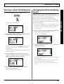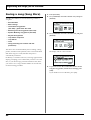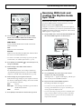
1
Owner’s Manual
Thank you, and congratulations on your choice of the BOSS
BR-1180/1180CD Digital Recording Studio.
Before using this unit, carefully read the sections entitled:
• USING THE UNIT SAFELY (page 2–3)
• IMPORTANT NOTES (page 4–5)
These sections provide important information concerning
the proper operation of the unit.
Owner's Manual
Additionally, in order to feel assured that you have gained a
good grasp of every feature provided by your new unit,
Owner’s manual should be read in its entirety. The manual
should be saved and kept on hand as a convenient reference.
■ Printing Conventions in This Manual
• Text or numerals enclosed in square brackets [ ] indicate buttons.
[PLAY]
PLAY button
[REC]
REC button
• Reference such as (p. **) indicate pages in this manual to which
you can refer.
Copyright © 2002 BOSS CORPORATION
All rights reserved. No part of this publication may be reproduced in any form
without the written permission of BOSS CORPORATION.
02900178
‘03-6-5N
USING THE UNIT SAFELY
The
symbol alerts the user to important instructions
or warnings.The specific meaning of the symbol is
determined by the design contained within the
triangle. In the case of the symbol at left, it is used for
general cautions, warnings, or alerts to danger.
Used for instructions intended to alert
the user to the risk of death or severe
injury should the unit be used
improperly.
Used for instructions intended to alert
the user to the risk of injury or material
damage should the unit be used
improperly.
* Material damage refers
other adverse effects
respect to the home
furnishings, as well
animals or pets.
The
symbol alerts the user to items that must never
be carried out (are forbidden). The specific thing that
must not be done is indicated by the design contained
within the circle. In the case of the symbol at left, it
means that the unit must never be disassembled.
to damage or
caused with
and all its
to domestic
The ● symbol alerts the user to things that must be
carried out. The specific thing that must be done is
indicated by the design contained within the circle. In
the case of the symbol at left, it means that the powercord plug must be unplugged from the outlet.
For the U.K.
IMPORTANT: THE WIRES IN THIS MAINS LEAD ARE COLOURED IN ACCORDANCE WITH THE FOLLOWING CODE.
001
008c
• Before using this unit, make sure to read the
instructions below, and the Owner’s Manual.
• Be sure to use only the AC adaptor supplied with
the unit. Also, make sure the line voltage at the
installation matches the input voltage specified on
the AC adaptor’s body. Other AC adaptors may use a
different polarity, or be designed for a different voltage,
so their use could result in damage, malfunction, or
electric shock.
..........................................................................................................
..........................................................................................................
002d
• Do not open or perform any internal modifications on the unit or its AC adaptor. (The only
exception would be where this manual provides
specific instructions which should be followed in
order to put in place user-installable options.)
..........................................................................................................
003
• Do not attempt to repair the unit, or replace parts
within it (except when this manual provides
specific instructions directing you to do so). Refer
all servicing to your retailer, the nearest Roland
Service Center, or an authorized Roland
distributor, as listed on the “Information” sheet.
..........................................................................................................
004
• Never use or store the unit in places that are:
• Subject to temperature extremes (e.g., direct
sunlight in an enclosed vehicle, near a heating
duct, on top of heat-generating equipment); or
are
• Damp (e.g., baths, washrooms, on wet floors);
or are
• Humid; or are
• Exposed to rain; or are
As the colours of the wires in the mains lead of this apparatus may not correspond with the coloured markings identifying
the terminals in your plug, proceed as follows:
The wire which is coloured BLUE must be connected to the terminal which is marked with the letter N or coloured BLACK.
The wire which is coloured BROWN must be connected to the terminal which is marked with the letter L or coloured RED.
Under no circumstances must either of the above wires be connected to the earth terminal of a three pin plug.
009
• Do not excessively twist or bend the power cord,
nor place heavy objects on it. Doing so can
damage the cord, producing severed elements and
short circuits. Damaged cords are fire and shock
hazards!
..........................................................................................................
010
• This unit, either alone or in combination with an
amplifier and headphones or speakers, may be
capable of producing sound levels that could
cause permanent hearing loss. Do not operate for
a long period of time at a high volume level, or at
a level that is uncomfortable. If you experience
any hearing loss or ringing in the ears, you should
immediately stop using the unit, and consult an
audiologist.
..........................................................................................................
For EU Countries
This product complies with the requirements of European Directive 89/336/EEC.
For the USA
FEDERAL COMMUNICATIONS COMMISSION
RADIO FREQUENCY INTERFERENCE STATEMENT
011
This equipment has been tested and found to comply with the limits for a Class B digital device, pursuant to Part 15 of the
FCC Rules. These limits are designed to provide reasonable protection against harmful interference in a residential
installation. This equipment generates, uses, and can radiate radio frequency energy and, if not installed and used in
accordance with the instructions, may cause harmful interference to radio communications. However, there is no guarantee
that interference will not occur in a particular installation. If this equipment does cause harmful interference to radio or
television reception, which can be determined by turning the equipment off and on, the user is encouraged to try to correct the
interference by one or more of the following measures:
– Reorient or relocate the receiving antenna.
– Increase the separation between the equipment and receiver.
– Connect the equipment into an outlet on a circuit different from that to which the receiver is connected.
– Consult the dealer or an experienced radio/TV technician for help.
• Do not allow any objects (e.g., flammable material,
coins, pins); or liquids of any kind (water, soft
drinks, etc.) to penetrate the unit.
This device complies with Part 15 of the FCC Rules. Operation is subject to the following two conditions:
(1) This device may not cause harmful interference, and
(2) This device must accept any interference received, including interference that may cause undesired operation.
• Dusty; or are
• Subject to high levels of vibration.
..........................................................................................................
BLUE:
NEUTRAL
BROWN: LIVE
..........................................................................................................
Unauthorized changes or modification to this system can void the users authority to operate this equipment.
This equipment requires shielded interface cables in order to meet FCC class B Limit.
007
• Make sure you always have the unit placed so it is
level and sure to remain stable. Never place it on
stands that could wobble, or on inclined surfaces.
..........................................................................................................
For Canada
NOTICE
This Class B digital apparatus meets all requirements of the Canadian Interference-Causing Equipment Regulations.
AVIS
Cet appareil numérique de la classe B respecte toutes les exigences du Règlement sur le matériel brouilleur du Canada.
2
012b
101b
• Immediately turn the power off, remove the AC
adaptor from the outlet, and request servicing by
your retailer, the nearest Roland Service Center, or
an authorized Roland distributor, as listed on the
"Information" page when:
• The unit and the AC adaptor should be located so
their location or position does not interfere with
their proper ventilation.
..........................................................................................................
• The AC adaptor, the power-supply cord, or the
plug has been damaged; or
• Objects have fallen into, or liquid has been
spilled onto the unit; or
• The unit has been exposed to rain (or otherwise
has become wet); or
• The unit does not appear to operate normally or
exhibits a marked change in performance.
..........................................................................................................
013
• In households with small children, an adult
should provide supervision until the child is
capable of following all the rules essential for the
safe operation of the unit.
..........................................................................................................
014
• Protect the unit from strong impact.
(Do not drop it!)
..........................................................................................................
015
• Do not force the unit’s power-supply cord to share
an outlet with an unreasonable number of other
devices. Be especially careful when using
extension cords—the total power used by all
devices you have connected to the extension
cord’s outlet must never exceed the power rating
(watts/amperes) for the extension cord. Excessive
loads can cause the insulation on the cord to heat
up and eventually melt through.
..........................................................................................................
016
• Before using the unit in a foreign country, consult
with your retailer, the nearest Roland Service
Center, or an authorized Roland distributor, as
listed on the “Information” sheet.
..........................................................................................................
022b
BR-1180
• Always turn the unit off and unplug the AC
adaptor before attempting installation of the CDR/RW drive (model no. CDI-BR-1).
..........................................................................................................
023
BR-1180CD
• DO NOT play a CD-ROM disc on a conventional
audio CD player. The resulting sound may be of a
level that could cause permanent hearing loss.
Damage to speakers or other system components
may result.
..........................................................................................................
102c
• Always grasp only the plug on the AC adaptor
cord when plugging into, or unplugging from, an
outlet or this unit.
..........................................................................................................
103b
• Whenever the unit is to remain unused for an
extended period of time, disconnect the AC
adaptor.
..........................................................................................................
104
• Try to prevent cords and cables from becoming
entangled. Also, all cords and cables should be
placed so they are out of the reach of children.
..........................................................................................................
106
• Never climb on top of, nor place heavy objects on
the unit.
..........................................................................................................
107c
• Never handle the AC adaptor or its plugs with
wet hands when plugging into, or unplugging
from, an outlet or this unit.
..........................................................................................................
108b
• Before moving the unit, disconnect the AC
adaptor and all cords coming from external
devices.
..........................................................................................................
109b
• Before cleaning the unit, turn off the power and
unplug the AC adaptor from the outlet.
..........................................................................................................
110b
• Whenever you suspect the possibility of lightning
in your area, disconnect the AC adaptor from the
outlet.
..........................................................................................................
115a
BR-1180
• Install only the specified CD-R/RW drive (model
no. CDI-BR-1). Remove only the specified screws.
..........................................................................................................
118
• Should you remove the optical connector caps,
make sure to put them in a safe place out of
children's reach, so there is no chance of them
being swallowed accidentally.
..........................................................................................................
3
IMPORTANT NOTES
291a
In addition to the items listed under “USING THE UNIT SAFELY” on page 2–3, please read and observe the following:
Power Supply
301
• Do not use this unit on the same power circuit with any
device that will generate line noise (such as an electric
motor or variable lighting system).
302
• The AC adaptor will begin to generate heat after long
hours of consecutive use. This is normal, and is not a
cause for concern.
307
• Before connecting this unit to other devices, turn off the
power to all units. This will help prevent malfunctions
and/or damage to speakers or other devices.
402
• Never use benzine, thinners, alcohol or solvents of any
kind, to avoid the possibility of discoloration and/or
deformation.
Additional Precautions
552
• Unfortunately, it may be impossible to restore the contents
of data that was stored on a hard disk or CD-R/RW disc
once it has been lost. Roland Corporation assumes no
liability concerning such loss of data.
553
• Use a reasonable amount of care when using the unit’s
buttons, sliders, or other controls; and when using its jacks
and connectors. Rough handling can lead to malfunctions.
Placement
554
351
• Never strike or apply strong pressure to the display.
• Using the unit near power amplifiers (or other equipment
containing large power transformers) may induce hum.
To alleviate the problem, change the orientation of this
unit; or move it farther away from the source of interference.
556
352a
• This device may interfere with radio and television
reception. Do not use this device in the vicinity of such
receivers.
352b
• Noise may be produced if wireless communications
devices, such as cell phones, are operated in the vicinity of
this unit. Such noise could occur when receiving or initiating a call, or while conversing. Should you experience
such problems, you should relocate such wireless devices
so they are at a greater distance from this unit, or switch
them off.
353
BR-1180CD
• Observe the following when using the unit’s floppy disk
drive. For further details, refer to “Before Using CD-R/
RW Discs” (p. 24).
• Do not place the unit near devices that produce a
strong magnetic field (e.g., loudspeakers).
• When connecting / disconnecting all cables, grasp the
connector itself—never pull on the cable. This way you
will avoid causing shorts, or damage to the cable’s
internal elements.
557
• A small amount of heat will radiate from the unit during
normal operation.
558a
• To avoid disturbing your neighbors, try to keep the unit’s
volume at reasonable levels. You may prefer to use
headphones, so you do not need to be concerned about
those around you (especially when it is late at night).
559a
• When you need to transport the unit, package it in the box
(including padding) that it came in, if possible. Otherwise,
you will need to use equivalent packaging materials.
561
• Use only the specified expression pedal (EV-5; sold
separately). By connecting any other expression pedals,
you risk causing malfunction and/or damage to the unit.
562
• Use a cable from Roland to make the connection. If using
some other make of connection cable, please note the
following precautions.
• Some connection cables contain resistors. Do not use
cables that incorporate resistors for connecting to this
unit. The use of such cables can cause the sound level
to be extremely low, or impossible to hear. For information on cable specifications, contact the manufacturer of the cable.
• Install the unit on a solid, level surface.
• Do not move the unit or subject it to vibration while
the drive is operating.
354a
• Do not expose the unit to direct sunlight, place it near
devices that radiate heat, leave it inside an enclosed
vehicle, or otherwise subject it to temperature extremes.
Excessive heat can deform or discolor the unit.
355
• To avoid possible breakdown, do not use the unit in a wet
area, such as an area exposed to rain or other moisture.
928
* When turning the unit upside-down, get a bunch of
newspapers or magazines, and place them under the four
corners or at both ends to prevent damage to the buttons
and controls. Also, you should try to orient the unit so no
buttons or controls get damaged.
929
Maintenance
401a
• For everyday cleaning wipe the unit with a soft, dry cloth
or one that has been slightly dampened with water. To
remove stubborn dirt, use a cloth impregnated with a
mild, non-abrasive detergent. Afterwards, be sure to wipe
the unit thoroughly with a soft, dry cloth.
4
* When turning the unit upside-down, handle with care to
avoid dropping it, or allowing it to fall or tip over.
IMPORTANT NOTES
Handling the Internal Hard
Disk Drive
• Please note that the hard disk is a consuming product. To
protect yourself against risk of loosing important data by
accidental disk damage, we recommend that you periodically save a backup copy on the CD-R/RW disc.
• Before performing any of the following actions, be sure to
perform the shutdown procedure (p. 30). Failure to do so
may result in the loss of song data or damage to the hard
disk.
• Do not turn off the power while the hard disk is operating.
• While using the BR-1180/1180CD, be careful not to subject
the unit to vibration or shock, and avoid moving the unit
while the power is turned on.
602
• Install the unit on a solid, level surface in an area free from
vibration. If the unit must be installed at an angle, be sure
the installation does not exceed the permissible range.
603
• Avoid using the unit immediately after it has been moved
to a location with a level of humidity that is greatly
different than its former location. Rapid changes in the
environment can cause condensation to form inside the
drive, which will adversely affect the operation of the
drive and/or damage CD-R/RW discs. When the unit has
been moved, allow it to become accustomed to the new
environment (allow a few hours) before operating it.
Handling CD-ROMs
853
• Do not use this unit for purposes that could infringe on a
copyright held by a third party. We assume no responsibility whatsoever with regard to any infringements of
third-party copyrights arising through your use of this
unit.
About the License Agreement
• The BR-1180/1180CD and its CD-R/RW capability are
designed to allow you to reproduce material to which you
have copyright, or material which the copyright owner
has granted you permission to copy. Accordingly, reproduction of Music CD or other copyrighted material
without permission of the copyright owner avoiding
technical prohibiting features of second-generation and
later copying like SCMS or others constitutes copyright
infringement and may incur penalties even in case such
reproduction is for your own personal use and enjoyment
(private use). Consult a copyright specialist or special
publications for more detailed infor-mation on obtaining
such permission from copyright holders.
Disclaimer of liability
• BOSS/Roland will take no responsibility for any “direct
damages,” “consequential damages,” or “any other
damages” which may result from your use of the BR1180/1180CD. These damages may include but are not
limited to the following events which can occur when
using the BR-1180/1180CD.
• Any loss of profit that may occur to you
801
• Permanent loss of your music or data
• Avoid touching or scratching the shiny underside
(encoded surface) of the disc. Damaged or dirty CD-ROM
discs may not be read properly. Keep your discs clean
using a commercially available CD cleaner.
Copyright
851
• Unauthorized recording, distribution, sale, lending, public
performance, broadcasting, or the like, in whole or in part,
of a work (musical composition, video, broadcast, public
performance, or the like) whose copyright is held by a
third party is prohibited by law.
• Inability to continue using the BR-1180/1180CD itself
or a connected device
204
• Windows is registered trademarks of Microsoft Corporation.
207
• Macintosh is registered trademark of Apple Computer,
Inc.
852a
• When exchanging audio signals through a digital
connection with an external instrument, this unit can
perform recording without being subject to the restrictions
of the Serial Copy Management System (SCMS). This is
because the unit is intended solely for musical production,
and is designed not to be subject to restrictions as long as
it is used to record works (such as your own compositions) that do not infringe on the copyrights of others.
(SCMS is a feature that prohibits second-generation and
later copying through a digital connection. It is built into
MD recorders and other consumer digital-audio
equipment as a copyright-protection feature.)
The explanations in this manual include illustrations that
depict what should typically be shown by the display.
Note, however, that your unit may incorporate a newer,
enhanced version of the system (e.g., includes newer
sounds), so what you actually see in the display may not
always match what appears in the manual.
5
Contents
USING THE UNIT SAFELY......................................................................2
IMPORTANT NOTES ...............................................................................4
Introduction to the BR-1180/BR-1180CD ............................................13
Panel Descriptions................................................................................16
Front Panel................................................................................................................................................. 16
CD-R/RW Drive ....................................................................................................................................... 20
Display ....................................................................................................................................................... 21
Rear Panel .................................................................................................................................................. 22
Before Using CD-R/RW Discs ..............................................................24
Quick Start ................................... 25
Listening to the Demo Songs ..............................................................26
(1) Connecting peripheral devices ......................................................................................................... 26
(2) Turn on the BR-1180/1180CD........................................................................................................... 27
(3) Listening to the demo songs ............................................................................................................. 28
Selecting a song—Song Select ..................................................................................................... 28
Playing Back a Song...................................................................................................................... 29
Changing the current position .................................................................................................... 29
Changing the song variation ....................................................................................................... 30
(4) Turning off the power ........................................................................................................................ 30
Recording/playing back a song...........................................................31
(1) Turn on the BR-1180/1180CD........................................................................................................... 31
(2) Selecting the song to be recorded ..................................................................................................... 31
Recording a new song .................................................................................................................. 31
(3) Connecting instruments..................................................................................................................... 32
Choose which jack you will use to connect your instrument................................................. 32
Press the INPUT SELECT button of the instrument that you want to record ..................... 33
Adjusting the input sensitivity.................................................................................................... 33
Monitoring the sound................................................................................................................... 33
(4) Using insert effects.............................................................................................................................. 34
Switch effect patches..................................................................................................................... 34
Recording without effects ............................................................................................................ 34
(5) About the Rhythm Guide .................................................................................................................. 35
Playing the rhythm guide ............................................................................................................ 35
Changing the Rhythm Arrangement ......................................................................................... 35
Changing the Tempo .................................................................................................................... 35
Tapping to change the tempo...................................................................................................... 36
(6) Recording ............................................................................................................................................. 36
Selecting the recording track ....................................................................................................... 36
Recording operations.................................................................................................................... 37
(7) Playing back recorded music ............................................................................................................ 38
Playback.......................................................................................................................................... 38
6
Contents
Adjusting the volume of each track............................................................................................ 38
Silencing the sound of specific tracks—Mute ........................................................................... 38
(8) Recording an additional performance while listening to an existing performance—Overdubbing....... 39
(9) Completing the song—Mixdown ..................................................................................................... 40
Setting the left-right positioning (pan) of the sound ............................................................... 40
Adjusting the tone—Equalizer.................................................................................................... 40
Adding width to the sound—Loop Effect ................................................................................. 40
Mixdown ........................................................................................................................................ 41
(10) Turning off the power ...................................................................................................................... 41
Advanced Use .............................. 43
Re-recording only a mistake—Punch-in/out ......................................44
Manually punching in/out ..................................................................................................................... 44
Manually punching in and out using [REC] ............................................................................. 44
Manually punching in and out using a foot switch ................................................................. 45
Auto punching in and out....................................................................................................................... 45
Specifying the area for recording................................................................................................ 45
How to Record............................................................................................................................... 46
Repeatedly Recording Over the Same Location (Loop Recording) .................................................. 46
Setting the portion to be repeated .............................................................................................. 46
How to Record............................................................................................................................... 47
Utilizing the V-Tracks ...........................................................................48
Changing V-Tracks ....................................................................................................................... 48
Naming a track (Track Name) ................................................................................................................ 49
Changing the final mastering tracks...................................................................................................... 49
Putting multiple tracks together—Bouncing......................................50
Using the insert effects ........................................................................51
Effect patches and banks ......................................................................................................................... 51
Editing insert effect settings.................................................................................................................... 52
Saving insert effects settings ................................................................................................................... 53
Copying an effect patch........................................................................................................................... 54
Changing the insert effect connections ................................................................................................. 55
Using the loop effects ..........................................................................56
Modifying the loop effect settings ......................................................................................................... 56
Chorus/Delay/Doubling............................................................................................................. 56
Reverb ............................................................................................................................................. 57
Reproducing the characteristics of
various monitor speakers (Speaker Modeling) ..................................58
Using speaker modeling.......................................................................................................................... 58
Editing the speaker modeling settings .................................................................................................. 59
Saving speaker modeling settings.......................................................................................................... 60
Copying speaker models ......................................................................................................................... 60
7
Contents
Registering a marker in your song—the Marker function.................61
Registering a marker ................................................................................................................................ 61
Clearing a marker ..................................................................................................................................... 61
Moving to the location of a marker........................................................................................................ 61
Editing a marker ....................................................................................................................................... 61
Changing the location of a marker ............................................................................................. 61
Naming a marker .......................................................................................................................... 62
Stopping automatically (Marker Stop).................................................................................................. 62
Registering/recalling the current mixer settings—Scenes ...............63
Registering/recalling/deleting scenes.................................................................................................. 63
Recalling a scene without changing the track volumes ...................................................................... 63
Search for the music’s start and end (Scrub/Preview)......................64
Scrubbing to find the music starting point ........................................................................................... 64
Changing the scrub points ...................................................................................................................... 65
Using Scrub and Preview to find the music ending point ................................................................. 65
Enabling the Preview Function ................................................................................................... 65
Using Scrub and Preview............................................................................................................. 65
Editing the performance—Track Editing ............................................66
Copying recorded data (Track Copy).................................................................................................... 66
Moving recorded data (Track Move)..................................................................................................... 68
Exchanging recorded data (Track Exchange)....................................................................................... 70
Inserting blank spaces in recorded data (Track Insert)....................................................................... 71
Deleting data and reconnecting the remaining data (Track Cut)...................................................... 72
Erasing performance data—Track Erase............................................................................................... 73
Canceling a recording or editing procedure—Undo/Redo ...............75
Reversing the last operation (Undo)...................................................................................................... 75
Canceling the Undo—Redo .................................................................................................................... 75
Organizing the songs you’ve recorded ..............................................76
Displaying song-related information (Song Information).................................................................. 76
Copying a Song (Song Copy).................................................................................................................. 76
Erasing songs (Song Erase) ..................................................................................................................... 77
Optimizing hard disk space (Song Optimize)...................................................................................... 78
Protecting a song (Song Protect) ............................................................................................................ 78
Protecting a song ........................................................................................................................... 78
Canceling song protect ................................................................................................................. 79
Naming songs (Song Name) ................................................................................................................... 79
Saving a song (Song Store)...................................................................................................................... 80
Using the Rhythm Guide ......................................................................81
Overview of the Rhythm Guide ............................................................................................................. 81
Selecting rhythm arrangements ............................................................................................................. 83
Creating rhythm arrangements .............................................................................................................. 83
Setting rhythm tempos for each measure individually (Tempo Map)............................................. 84
Copying rhythm arrangements.............................................................................................................. 85
Deleting rhythm arrangements .............................................................................................................. 85
Creating rhythm patterns........................................................................................................................ 86
Recording preparations................................................................................................................ 86
8
Contents
Creating rhythm patterns using Realtime Recording.............................................................. 86
Recording with uniform timing (Quantize) .............................................................................. 87
Creating rhythm patterns using Step Recording...................................................................... 88
Making corrections in rhythm patterns (Microscope) ............................................................. 89
Changing the amount of bounce in the rhythm patterns (Swing)......................................... 90
Changing the rhythm pattern name........................................................................................... 90
Copying rhythm patterns ............................................................................................................ 90
Deleting rhythm patterns............................................................................................................. 90
Loading rhythm patterns from CD-R/RWs (SMF Import)................................................................ 91
Using loop phrases...............................................................................92
Creating loop phrases .............................................................................................................................. 92
Creating a loop phrase from a portion of the audio tracks..................................................... 92
Creating a loop phrase by copying waveform data on a computer (Loop Phrase Import) .............. 93
Editing the loop phrase settings............................................................................................................. 94
Assigning loop phrases to the track buttons ........................................................................................ 95
Erasing loop phrases ................................................................................................................................ 95
Creating rhythm arrangements by arranging loop phases ................................................................ 96
Copying loop phrases arranged in rhythm arrangements to audio tracks...................................... 97
Copying loop phrases .............................................................................................................................. 98
Creating audio CDs (BR-1180CD)........................................................99
Mastering ................................................................................................................................................... 99
Using Auto Fade In/Out............................................................................................................ 100
Specifying an interval of several seconds between songs (Pre-gap)............................................... 102
Writing the song ..................................................................................................................................... 102
Writing by adding songs one at a time (Track At Once)....................................................... 102
Writing multiple songs all at one time (Disc At Once).......................................................... 104
Playing back Audio CDs ....................................................................................................................... 105
Enabling playback on ordinary CD players (Finalize)...................................................................... 106
Importing songs from audio CDs to the audio tracks ...................................................................... 106
Editing the Mastering Tool Kit settings .............................................................................................. 107
Creating a new patch.................................................................................................................. 107
Saving patch settings .................................................................................................................. 108
Copying a patch .......................................................................................................................... 108
Using the CD-R/RW to exchange data (BR-1180CD) .......................110
Saving recorded songs and data to CD-R/RW discs ........................................................................ 110
Saving songs to CD-R/RW discs (Song Backup) ................................................................... 110
Loading saved songs to the BR-1180CD (Song Recover) ...................................................... 111
Saving data on the hard disk to CD-R/RW discs .............................................................................. 112
Saving data on the hard disk to CD-R/RW discs (User Backup) ........................................ 112
Loading saved songs to the BR-1180CD (User Recover)....................................................... 113
Saving the entire content of the hard disk to CD-R/RWs................................................................ 115
Saving the content of the hard disk to CD-R/RW discs (HDD Backup) ............................ 115
Loading the saved content of the hard disk to the BR-1180CD (HDD Recover) ............... 116
Copying and writing waveform data.................................................................................................. 116
Copying waveform data from a computer to the audio tracks (WAV/AIFF Import) .................... 116
Copying audio track waveform data to computers (WAV/AIFF Export) ......................... 118
Erasing CD-RW data.............................................................................................................................. 120
9
Contents
Synchronizing with MIDI devices ......................................................121
MIDI Fundamentals ............................................................................................................................... 121
Using an external MIDI sound module to play the rhythm guide ................................................. 121
Synchronizing the performance of an external MIDI sequencer to the BR-1180/1180CD (Master) ........... 122
Switching the display of the TIME field .................................................................................. 123
Operating MMC-compatible devices with the BR-1180/1180CD................................................... 124
Receiving MIDI clock and creating the Rhythm Guide Sync Track ............................................... 125
Using MIDI to control track volume—MIDI Faders...........................127
Turning MIDI Fader on and off............................................................................................................ 127
Setting the MIDI Fader Transmit and Receive channels .................................................................. 127
Setting the expression pedal MIDI channel........................................................................................ 128
Confirming the current fader positions .............................................................................................. 128
Other Convenient Functions..............................................................129
Changing the position of the input sound.......................................................................................... 129
Repeating Playback (Repeat) ................................................................................................................ 129
Tuning an instrument (Tuner).............................................................................................................. 130
Changing to the tuner................................................................................................................. 130
Explanation of the indications that appear while tuning...................................................... 130
Tuning........................................................................................................................................... 130
Setting the reference pitch of the tuner .................................................................................... 131
Copying difficult songs (Phrase Trainer)............................................................................................ 131
Slowing down the speed (Time Stretch function) .................................................................. 131
Canceling the center sound (Center Cancel function) ........................................................... 132
Creating a master tape that prohibits digital copying ...................................................................... 132
Switching the signal indicated in the level meter (Pre-/Post-Fader) ............................................. 133
Initializing the BR-1180/1180CD’s settings (Initialize)..................................................................... 133
Setting the time before the CD-R/RW drive is stopped (Hold Time) ............................................ 135
Initializing the hard disk (Disk Initialize)........................................................................................... 135
Viewing information about the hard disk (Hard Disk Information).............................................. 136
Using condenser mics (Phantom Power) ............................................................................................ 137
Mixing the output from an external MIDI device
with the output from your BR-1180/1180CD (Audio Sub Mix)...................................................... 138
Adjusting the Display Contrast............................................................................................................ 139
Using an external MIDI sound module to sound the playback of SMFs (SMF Player) ............... 139
Mixer effect parameter functions ......................................................141
EQ (Equalizer)......................................................................................................................................... 141
Loop Effect............................................................................................................................................... 141
CHORUS/DELAY/DOUBL’N (Chorus/Delay/Doubling) ................................................ 141
REVERB ........................................................................................................................................ 142
Insert effect algorithm list ..................................................................143
BANK: GUITAR ..................................................................................................................................... 143
1. COSM GUITAR AMP............................................................................................................. 143
2. ACOUSTIC SIM ...................................................................................................................... 143
3. BASS SIM.................................................................................................................................. 143
4. COSM COMP GUITAR AMP................................................................................................ 144
5. ACOUSTIC GUITAR .............................................................................................................. 144
6. BASS MULTI............................................................................................................................ 144
7. COSM BASS AMP................................................................................................................... 144
10
Contents
8. COSM COMP BASS AMP...................................................................................................... 145
BANK: MIC ............................................................................................................................................. 145
9. VOCAL MULTI ....................................................................................................................... 145
10. VOICE TRANSFORMER ..................................................................................................... 145
11. COSM VOCAL COMP ......................................................................................................... 146
12. MIC MODELING .................................................................................................................. 146
BANK: LINE............................................................................................................................................ 146
13. STEREO MULTI .................................................................................................................... 146
14. LO-FI BOX.............................................................................................................................. 146
BANK: SIMUL ........................................................................................................................................ 147
15. VO+GT.AMP ......................................................................................................................... 147
16. VO+AC.SIM ........................................................................................................................... 147
17. VO+ACOUSTIC .................................................................................................................... 147
Insert effect parameter functions ......................................................148
Acoustic Guitar Simulator..................................................................................................................... 148
Acoustic Processor.................................................................................................................................. 148
Bass Simulator......................................................................................................................................... 148
Bass Cut Filter ......................................................................................................................................... 149
Chorus ...................................................................................................................................................... 149
Compressor ............................................................................................................................................. 149
COSM Comp/Limiter (COSM Compressor/Limiter) ...................................................................... 149
De-esser.................................................................................................................................................... 150
Defretter ................................................................................................................................................... 150
Delay......................................................................................................................................................... 151
Distance.................................................................................................................................................... 151
Doubling .................................................................................................................................................. 151
Enhancer .................................................................................................................................................. 151
Equalizer .................................................................................................................................................. 152
Flanger...................................................................................................................................................... 152
Foot Volume ............................................................................................................................................ 152
Limiter...................................................................................................................................................... 153
Lo-Fi Box .................................................................................................................................................. 153
Mic Converter ......................................................................................................................................... 154
Noise Suppressor.................................................................................................................................... 155
Octave....................................................................................................................................................... 155
Phaser ....................................................................................................................................................... 155
Pitch Shifter ............................................................................................................................................. 155
Preamp ..................................................................................................................................................... 156
Ring Modulator....................................................................................................................................... 157
Slow Attack ............................................................................................................................................. 157
Speaker Simulator .................................................................................................................................. 157
Tremolo/Pan........................................................................................................................................... 158
Voice Transformer.................................................................................................................................. 158
Wah........................................................................................................................................................... 158
Speaker Modeling parameter functions............................................160
SP Modeling (speaker modeling)......................................................................................................... 160
Bass Cut Filter ......................................................................................................................................... 160
Low Freq Trimmer (low frequency trimmer)..................................................................................... 161
High Freq Trimmer (high frequency trimmer) .................................................................................. 161
Limiter...................................................................................................................................................... 161
11
Contents
How the Mastering Tool Kit Parameters Work .................................162
Equalizer .................................................................................................................................................. 162
Bass Cut Filter ......................................................................................................................................... 163
Enhancer .................................................................................................................................................. 163
Input ......................................................................................................................................................... 163
Expander.................................................................................................................................................. 163
Compressor ............................................................................................................................................. 164
Mixer ........................................................................................................................................................ 165
Limiter...................................................................................................................................................... 165
Output ...................................................................................................................................................... 165
Rhythm Arrangement/Pattern List ....................................................166
Preset Rhythm Arrangement ................................................................................................................ 166
Preset Rhythm Pattern........................................................................................................................... 167
Troubleshooting..................................................................................168
Error message list...............................................................................171
Parameter List .....................................................................................174
MIDI Implementation...........................................................................179
MIDI Implementation Chart ................................................................184
Specifications......................................................................................185
Index.....................................................................................................186
Track Sheet..........................................................................................190
12
Introduction to the BR-1180/BR-1180CD
Main Features
Simple operation
The BR-1180/1180CD is designed to be operated as easily as
a cassette tape recorder, even by beginners.
Additionally, the large liquid crystal display allows you to
view and confirm various information in graphic format.
Whether you are simply preparing a demo tape, or are
getting ready to go to master with your first album, the
simple operation of the BR-1180/1180CD allows you to
create digital recordings the very day you take it out of the
box.
Two versatile digital effects processors
The BR-1180/1180CD contains two types of effect unit. One
type is for recording (insert effect) and the other type is
independent send/return effects (loop effect). These two
types can be used simultaneously. This means that the BR1180/1180CD is all you need to produce a sophisticated song
without using external effect devices.
The BR-1180/1180CD has many built-in simulations and
effects, including amp simulation with COSM for a wide
variety of insert effects.
You also get a wide variety of effects, including everything
from the guitar effects you would expect, to vocal and
keyboard multi-effects and mic simulators.
Digital audio workstation
The loop effects include spatial effects such as chorus, delay
and reverb, which are vital for proper stereo mixdown.
All processes are fully digital
By using the insert effects and loop effects together, you can
add both sound and spatial effects to your music at one time.
In addition to a digital mixer and digital hard disk recorder,
the BR-1180/1180CD also features two internal digital effects
systems.
By connecting a DAT recorder, MD recorder, or other digital
recorder to the DIGITAL OUT jacks, you can perform all the
steps needed for professional-level music recording,
including editing, bouncing tracks, applying effects, and
mixing down, entirely within the digital realm, so there is no
degradation in the signal quality.
Handles uncompressed recording and
playback
The BR-1180/1180CD handles linear 16-bit uncompressed
recording and playback, allowing you to record with the
same sound quality as the original, with no deterioration in
the sound.
Of course, when you want to be economical with your
recording time, yet maintain sound quality, you can still
record and play back using conventional compression
techniques.
Equipped with V-Tracks
The BR-1180/1180CD includes a total of ten recording tracks,
allowing you to record and play back eight independent
tracks with two-track stereo recording and playback, making
it possible to get simultaneous two-track recording or
simultaneous ten-track playback.Moreover, each track
incorporates eight virtual tracks, called “V-Tracks,” for a
total recording capability of 10 x 8 = 80 tracks!
This increased versatility allows you to do things such as
record numerous takes of a guitar solo, which you can later
choose from when putting it all together.
For a more detailed explanation of insert and loop
effects, refer to “What is an insert effect?” (p. 34) and
“What is a loop effect?” (p. 40) respectively.
Editing Functions
With the BR-1180/1180CD, you can perform editing
operations such as copying, moving, and erasing, previously
unheard of with multitrack recorders that use tapes.
For example, you can have just a four-measure drum pattern
repeated any number of times you want for use with break
beat music, and have the same chorus inserted both at the
beginning and end of a song.
Non-destructive editing
Since this is hard disk recording, you can perform nondestructive editing.With non-destructive editing, after
performing any editing and recording operations, you can
still return your data to its previous state (undo and redo
functions).
“Canceling a recording or editing procedure” (p. 75)
Saved mixer settings
You can register up to eight different mixer and effect
settings configurations (scenes) for each song.
This allows you to call up previous settings quickly and
easily, which comes in handy when adjusting the balance
during mixdown, or when comparing effects.
“Registering/recalling the current mixer settings” (p. 63)
13
Introduction to the BR-1180/BR-1180CD
Quick movement to a point
You can place markers at up to 100 locations (points) of your
choosing in a song (Marker function).
If you assign markers to locations such as the end of the
opening or the beginning of a solo, you will be able to move
instantly to the point where you wish to begin listening.
“Registering a marker in your song” (p. 61)
You can also name the markers, which can be quite
helpful during the editing process.
PCM Rhythm Guide Function
The BR-1180/1180CD also features a PCM Rhythm Guide
function (p. 81) that comes in handy when you want to
record phrases and ideas for songs that come to mind.
Simply select an appropriate rhythm pattern, and set the
tempo.
Furthermore, by combining one-measure rhythm patterns,
you can then use the Rhythm Guide to convert them into a
single song.
* You can create music CDs with the BR-1180 by equipping it
with the optional CDI-BR-1 CD-R/RW drive.
Loop Phrase Function
You can import commercially available phrase data via CDR/RW, and save the data to the BR-1180CD’s hard disk.
You can freely set the tempo for these phrase loops later on
and play them back in sync with the audio tracks, allowing
you to easily create styled music with performances layered
over break beats.
Equipped with chromatic tuner
(C1 to B6 sound range)
Your BR-1180/1180CD is also equipped with a chromatic
tuner so that you can tune your guitar or bass while it is still
connected to the BR-1180/1180CD (p. 130).
Phrase Trainer Function
“Creating rhythm arrangements” (p. 83)
When you play back the song you have recorded from the
CD player or the MD player, you can slow down the tempo
without changing the pitch. Also, you can remove the sound
you hear at the center (such as vocals and guitar solo) from
the song (p. 131).
By recording using the Rhythm Guide function, editing
one measure at a time is greatly simplified.
Full complement of connectors
(jacks)
Mastering Tool Kit
The BR-1180/1180CD includes a Mastering Tool Kit, which
you can use for making final volume adjustments and other
preparations for the song being mixed down.
Your BR-1180/1180CD is equipped with the input jacks
shown below.
GUITAR/BASS:
This high-impedance input jack allows you to directly
connect your guitar or bass (accepts 1/4” phone plugs).
Now you can easily maximize compression and carry out
other tasks for creating music CDs.
MIC 1, MIC 2:
Burn CDs using just the BR-1180CD
These are mic input jacks (phone plug or XLR). These permit
use of both balanced as well as unbalanced input.Phantom
power can be supplied to the XLR connectors.
The BR-1180CD is equipped with a CD-R/RW pre-installed.
This lets you burn your recorded songs as is right to CD-R/
RW discs, making it a breeze to create your own music CDs.
You can also use the CD-R/RW to create backups of your
music data.
* To play back on conventional CD players, use CD-R discs.
You cannot play back CD-R/RW discs on such CD players.
However, some CD players may be unable to play even CD-R
discs. Still, you can play both CD-R and CD-R/RW discs on
the BR-1180CD itself.
14
“Using condenser mics” (p. 137)
LINE:
These jacks accept stereo input from keyboards, CD players,
and other devices at line level (RCA phono jacks).
For output, in addition to the LINE OUT jacks (stereo RCA
phono jacks), optical DIGITAL OUT connectors are also
provided for high-quality digital recording to digital audio
recording devices (e.g., DAT recorders and MD recorders).
Introduction to the BR-1180/BR-1180CD
About Disk Space
The BR-1180/1180CD is equipped with a 20 GB internal hard
disk.
With this disk you can record up to approximately 200 hours
or more in LV2 mode (in terms of mono tracks).
What are V-Tracks?
Each track consists of eight virtual tracks, and you can
choose any one of these tracks for recording or playback.
This means that you can record to up to a maximum of
80 tracks, and then select any ten of them to play back.
These virtual tracks that make up the actual tracks are
called “V-Tracks.”
fig.00-01
V-Track1
V-Track2
V-Track3
V-Track4
V-Track5
V-Track6
V-Track7
V-Track8
A “Track Sheet” is provided at the rear of this
manual (p. 190), which you make copies of, and fill
in when recording music to V-Tracks.
What is COSM
(Composite Object Sound Modeling)?
Technology that virtually reconstructs an actually
existing structure or material using a different means is
called “modeling” technology. COSM is proprietary
Roland technology that creates new sounds by
combining various sound modeling technologies.
What is a CD-R disc?
CD-R (Compact Disc Recordable) is a CD to which data
can be written. It is not possible to erase or move the
data that has been written.
What is a CD-RW disc?
CD-RW (Compact Disc ReWritable) is a CD that can be
written and erased. Data that has been written can be
erased, and new data written.
15
Panel Descriptions
Front Panel
fig.00-21
3
1
2
30 31
38 39
4
5
6
7
9
10
11
8
12
13
14
15
19 20 21 22
25
32
26
33
35
34
37
16 17 18 28
23
27
24
1. POWER Switch
This is the power switch. It turns the power of the BR-1180/
1180CD on/off.
36
29
GUITAR/BASS, MIC 2:
The GUITAR/BASS jack (for guitar or bass) or the MIC 2
jack (for mic) will be selected.
MIC 1:
2. SENS knob
Use this knob to adjust the sensitivity at the input jacks (e.g.,
GUITAR/BASS, MIC 1, and MIC 2).
3. PEAK indicator
This indicator enables you to determine the degree of
distortion in the sound (input source) being input at the
various input jacks (e.g., GUITAR/BASS, MIC 1, and MIC 2).
This indicator lights at a level 6 dB lower than where sound
distortion occurs. Adjust the input sensitivity with the SENS
knob so that this indicator lights only occasionally, at those
moments when you play your guitar (or other instrument) at
its loudest.
4. INPUT SELECT buttons
Use these buttons to select the input source (input jack) that
you wish to record. The indicator of the selected button will
light. You can mute (silence) the input sound by pressing a
button that is lit.
The MIC 1 jack (for microphone) will be selected.
LINE:
For selecting the LINE jack (stereo) for the line inputs,
such as keyboards or CD players.
SIMUL:
Pressing the GUITAR/BASS, MIC 2 button and the MIC
1 button simultaneously allows you to record using both
of these inputs at the same time. The input sources will
be GUITAR/BASS and MIC 1 if an instrument is
connected to the GUITAR/BASS jack, while MIC 1 and
MIC 2 are selected if a mic is connected to the MIC 2
connector.
* If an instrument and mic are connected to both the GUITAR/
BASS jack and the MIC 2 jack respectively, the GUITAR/
BASS jack will be selected automatically.
* If the INPUT SELECT setting is changed, the insert effect
bank changes automatically (p. 51).
AF method is enabled when either the GUITAR/BASS,
MIC 2 button or MIC 1 button is alone selected.
16
Panel Descriptions
10. MARKER
What is AF method
(Adaptive Focus method)?
This is a proprietary method from Roland that vastly
improves the signal-to-noise (S/N) ratio of the A/D and
D/A converters.
5. EFFECTS button
Press this button to call up the screens used for selecting
patches for the insert effects (p. 51) and for editing settings.
6. INPUT LEVEL Knob
Use this knob to adjust the volume of the input source.
* If you use the INPUT LEVEL knob to turn down the volume
of the input source during recording, the sound will be
recorded in the audio track at a low volume, so that noise will
be more apparent when you raise the volume of the audio track
for playback. If you wish to lower the monitor volume of the
input source during recording, you should use the MASTER
fader or the PHONES VOLUME knob to lower the volume.
7. TUNER ON/OFF Button
Use this button to turn on and off the tuner (p. 130).
8. REC MODE (recording mode) Button
This button selects the recording mode of the recorder. There
are three recording modes.
INPUT:
The sound of the mic or instrument connected to the
input jacks will be recorded. The unit is normally used in
this mode.
BOUNCE:
Use this button to copy the recordings on multiple
separate tracks together on two tracks (or one track).
MASTERING:
Enables use of the Mastering Tool Kit and mastering on
tracks 9/10.
This cannot be used with other tracks.
9. REC MODE (recording mode) Indicators
These indicators show the current recording mode. When
you switch the recording mode using the REC MODE button,
the INPUT, BOUNCE, or MASTERING indicator lights
accordingly.
These buttons are used for settings related to the Marker function.
MARK Button
This button assigns a marker at the desired location in a
song. When you press this button, a marker will be
assigned to the current location.
Markers are numbered sequentially from the beginning
of the song. Each marker can also be given a name. The
marker field of the display will indicate the marker for
the current location if a marker has been assigned at the
current location, or the previous marker if no marker has
been assigned at the current location. If you assign
markers in a song, it will be easier to tell which part of a
song is currently playing or the like.
“Registering a marker in your song” (p. 61)
SEARCH
button:
This button jumps you to the location of the previous marker.
SEARCH
button:
This button jumps you to the location of the next marker.
CLEAR Button:
This button erases a marker. When you press this button,
the marker currently displayed in the marker field of the
display will be erased.
11. AUTO PUNCH IN/OUT
These buttons are used to make settings for the auto punchin/out function.
ON/OFF Button:
This button switches the auto punch-in/out function
on/off. When this is on, the button indicator will light.
IN Button:
This button specifies the punch-in location. Press this
button to set the punch-in location at the current location
in the track. When set, the indicator on this button will
light. After setting the punch-in location, you can jump
to the punch-in location by pressing this button.
OUT Button:
This button specifies the punch-out location. Press this
button to set the punch-out location at the current
location in the track. When set, the indicator on this
button will light. After the punch-out location is set, you
can press this button to automatically jump to the punchout location.
17
Panel Descriptions
DELETE Button:
This button erases the punch-in/out locations that were
stored at the IN and OUT buttons. By holding down this
button and pressing either IN or OUT, you can erase the
location that was stored at the respective button. The
indicator of the corresponding button will go dark.
20. EQ (equalizer) Button
Pressed to access a screen where you can make equalizer
settings to adjust the tone of each track (p. 40).
“Mixer effect parameter functions” (p. 141)
12. ZERO Button
21. CHORUS/DELAY Button
Press to jump to the beginning of the track.
This calls up the settings screen for the volume level sent
from each track to the loop effects chorus/delay (the send
level), the chorus/delay switching and parameter settings
screen, and other screens (p. 56).
13. REW Button
The song will rewind while you hold down the button.
14. FF Button
“Mixer effect parameter functions” (p. 141)
The song will fast-forward while you hold down the button.
22. REVERB Button
15. REPEAT Button
This calls up the settings screen for the volume level sent
from each track to the loop effects reverb (the send level) and
the reverb parameter settings screen (p. 57).
You can specify a region that you wish to hear, and hear it
repeatedly (p. 129).
This feature is useful if you want to repeatedly play back the
recording between the punch-in and out locations (p. 44)
until you are satisfied or use the phrase trainer (p. 131) to try
to copy a difficult phrase recorded from a CD or the like.
16. STOP Button
Stops recording or playback of the song.
17. PLAY Button
Plays back songs. When [REC] is pressed and the REC
indicator is flashing, press [PLAY] to start recording. During
recording or playback, the indicator on the button lights in
green.
“Mixer effect parameter functions” (p. 141)
23. AUDIO TRACK MIXER fader 1–8, 9/10
For controlling the volumes of each track during playback.
Tracks 9 and 10 are linked as a stereo pair, so moving one of
the faders controls the volume level for both tracks
simultaneously.
* Hereafter, the AUDIO TRACK MIXER faders shall be
referred to as the “TRACK faders.”
24. REC TRACK (Recording Track)
button 1–8, 9/10
Use these buttons to select to which track you will record.
18. REC (Recording) Button
This is the Record button. In addition to the Recording
operation, it is also used for manual punch-in/out. While in
recording standby, the indicator on this button flashes in red,
and during recording, it lights in red.
19. PAN Button
Pressed to access a screen where you can set the pan (left/
right location of the sound) for the playback of each track or
for the input sound (p. 40, 129).
Tracks 9 and 10 are linked as a stereo pair, so both tracks are
selected when one of their buttons is pressed.
The button of the track selected will flash in red and then
light in red when recording begins. When recording is
finished, the button of the selected track will light alternately
in orange and green. The relationship between the indicator
and the track conditions is given below.
Unlit:
This track contains no recorded data.
Green:
An audio track that contains recorded data.
18
Panel Descriptions
Flashing in green:
The track contains recorded data but has been muted
(silenced)
Flashing in red:
The track is selected as the recording destination, and is
in recording standby.
Red:
The track is now being recorded
Lighting alternately in orange and green:
This track contains recorded data and is selected for
recording.
Flashing in orange:
The track contains recorded data but has been muted,
and is also selected for recording
25. PHRASE TRAINER
Use this button to perform the settings for the phrase trainer
function.
CENTER CANCEL Button:
27. STEREO RHYTHM/LOOP
(Rhythm Guide/Loop Phrase Sequence)
Makes the settings affecting the Rhythm Guide and Loop
Phrase Sequence functions (p. 81, p. 92).
AUTO/ON/OFF Button:
Switches the Rhythm Guide function to Auto/On/Off
and the Loop Phrase Sequence On/Off.
EDIT Button:
Calls up the screen for setting the Rhythm Guide and
Loop Phrase Sequence patterns and tempos.
Fader 11
Adjusts the Rhythm Guide and Loop Phrase Sequence
volume levels.
TAP Button
You can set the tempos for the Rhythm Guide and Loop
Phrase Sequence to the timing you’ve used in tapping
this button.
28. V-TRACK Button
When using the Phrase Trainer, this button switches the
Center Cancel function on/off, allowing you to cancel
the vocal or other sound that is heard from the center.
When this is on, the button indicator will light.
Use this button to call up the screen for selecting a V-Track.
“Canceling the center sound” (p. 132)
29. TRACK MUTE Button
TIME STRETCH Button:
When using the Phrase Trainer, this button switches the
Time Stretch function on/off, allowing you to slow
down the playback speed. When this is on, the button
indicator will light.
“Slowing down the speed” (p. 131)
26. MASTERING TOOL KIT Button
Used in MASTERING mode, this button is used for
switching the Mastering Tool Kit on and off, and for calling
up the screen for changing the settings.
“What are V-Tracks?” (p. 15)
“Utilizing the V-Tracks” (p. 48)
By holding down this button and pressing a REC TRACK
button whose indicator is lit green, you can mute that track
during playback, regardless of the position of its TRACK
fader. When you repeat the same action, muting will be
defeated. While muted, the REC TRACK button of that track
will blink green. (p. 38)
* If a recording track was muted, muting will be defeated when
recording ends.
30. UTILITY Button
Pressed to access a variety of functions, including track
editing, song management, and disk operations.
31. UNDO/REDO Button
For undoing the last-performed recording or editing
operation and returning the data to its previous state. By
pressing this button once again, you can bring back the
canceled recording or re-execute the editing operation. (p. 75)
19
Panel Descriptions
32. TIME/VALUE Dial
Ordinarily, you use this dial to shift the current position
within a song (e.g., fast forwarding and rewinding). It is also
used to change the values of the various function settings.
CD-R/RW Drive
fig.00-22
2
1
4
33. CURSOR Buttons
Press these buttons to move the cursor within the screen.
34. ENTER/YES Button
Press this button to confirm a selection or a value being
entered.
3
Drive unit into which CD-R/RW discs are inserted (BR1180CD only).
* CDI-BR-1 (sold separately) can be installed in the BR-1180.
1. Disc Tray
Place the CD to be loaded on this tray.
35. EXIT/NO Button
Press this button to return to the previous screen or cancel
the last entry.
36. MASTER fader
2. Access Indicator
This indicator will light when the inserted CD-R/RW disc is
being read or when data is being written to the CD-R/RW
disc.
Controls the overall volume of the BR-1180.
3. Eject Button
37. CD-R/RW
Press this button to eject the CD-R/RW disc. You cannot eject
the CD-R/RW disc unless the power is on.
AUDIO CD WRITE/PLAY Button
Used for creating music CDs, and for simple playback.
* Available only with the BR-1180CD. The BR-1180 does not
feature this function.
DATA SAVE/LOAD Button
Used for saving recorded songs and loading saved data
to the BR-1180.
* Available only with the BR-1180CD. The BR-1180 does not
feature this function.
LOOP PHRASE IMPORT Button
Used for importing break beats and other loop phrases.
38. MIDI Indicator
Lights up to indicate that MIDI messages are being received
through the MIDI IN connector.
39. HD ACCESS indicator
Lights while data is being written to the hard disk.
* Never turn off the power while this is lit. Doing so may
damage the hard disk, possibly rendering it permanently
unusable.
20
If you need to eject a disc after the power has been
turned off, always eject the disc by turning the power
back on, then pressing the Eject button. Forcibly ejecting
may result in damage to the disk drive.
4. Emergency eject hole
This hole allows the disc tray to be opened in case of an
emergency. (p. 24)
Panel Descriptions
Display
4. FRAME
fig.00-23
1
2
3
4
Displays the frame number of the current position of the
song.
At the factory settings, one second is set to 30 frames (nondrop). This is one type of a specification known as MTC
(MIDI Time Code), and when you use the CDX-1 to play in
synchronization with another MIDI device, you will need to
set both devices to the same MTC type.
“Synchronizing with MIDI devices” (p. 121)
5
6
7
5. INFORMATION
Displays the menu screen, parameter setting screen, or other
information, depending on the type of settings being made.
If the screen is difficult to view, see “Adjusting the Display
Contrast” (p. 139).
1. MARKER
This indicates the marker number of the current location. If
no marker has been assigned to the current location, the
number of the previous marker is shown.
In addition, “- - -” is displayed when the current location is
earlier than the point at which the marker numbered “001” is
set, or when no markers have been set.
2. MEASURE
Displays the measure number and beat of the current
position within the song. The left number is the measure
number, and the right number is the beat.
Displays song information (marker names, type of data
recorded, remaining recording time) in PLAY mode.
6. MIXER/TRACK
During play mode, the volume levels of instruments being
input, and volume levels of each track are displayed.
When the BR-1180/1180CD is shipped, this will indicate the
volume level of the volume level of the signal that has passed
through the TRACK faders (post-fader).
If you want to display the volume level of the signal prior to
passing through the faders (pre-fader), refer to “Switching
the signal indicated in the level meter” (p. 133).
7. MASTER
In Play mode, this graphically indicates the volume level of
the signal that has passed through the MASTER fader.
3. TIME
The time of the current location in the song is displayed as
“** hours ** minutes ** seconds.”
21
Panel Descriptions
Rear Panel
fig.00-24
13
7
14
16
12
11 10
9 8
15
1
6
5 4
3
2
1. GUITAR/BASS Jack
5. LINE OUT Jacks
High-impedance input jack to directly connect your guitar or
bass.
These are output jacks for the analog audio signal. You can
connect MD recorders, tape recorders, or other recording
devices to record the output analog signal from the BR-1180/
1180CD.
2. MIC 2 jack (TRS Phone)
MIC 2 Connector (XLR Type)
Input jack/connector for use with mics. Two types are
provided, TRS balanced input (p. 27) and XLR balanced
input.
You can have +48 V phantom power supplied when using
the XLR type connectors.
“Using condenser mics” (p. 137)
* If mics are connected both to the TRS phone jack and the XLR
connector, the TRS phone jack is selected automatically.
* If an instrument is connected to the GUITAR/BASS jack
while a mic is also connected to the MIC 2 jack (or connector),
the GUITAR/BASS jack is selected automatically.
3. MIC 1 (VOCAL) Jack (TRS Phone)
MIC 1 (VOCAL) Connector (XLR Type)
These jacks allow a mic to be connected. Two types are
provided, TRS balanced input (p. 27) and XLR balanced
input.
You can have +48 V phantom power supplied when the XLR
type connectors are used.
* Depending on the settings, you can output a mix of the signal
input to LINE IN with the LINE OUT signal (Audio Sub
Mix: p. 138).
6. PHONES VOLUME Knob
Adjusts the headphone volume.
7. PHONES Jack
Headphones (sold separately) are connected here.
8. EXP PEDAL Jack
A separately sold expression pedal (Roland EV-5) can be
connected to this input jack. By using an expression pedal,
you can use the built-in effects processor to apply wah pedal
and other effects.
9. FOOT SW (Foot Switch) Jack
This is an input jack for connecting a separately sold foot
switch (BOSS FS-5U, Roland DP-2). You can use a foot switch
to start/stop a song, or to perform punch-in/out.
Using the foot switch (p. 45)
“Using condenser mics” (p. 137)
4. LINE IN Jacks
These are input jacks for analog audio signals. These jacks
are used to connect CD players and other audio devices and
keyboards, rhythm machines, and other external sound
sources.
22
10. DIGITAL OUT Connector
Optical connector for outputting digital audio signals. The
same sound that is output from LINE OUT is also output
from DIGITAL OUT, so you can digitally record the output
from the BR-1180/1180CD to DAT recorders, MD recorders,
and other digital recording devices.
Panel Descriptions
11. MIDI IN Connector
Connectors for receiving MIDI messages. Use by connecting
to the MIDI OUT connectors on external MIDI devices (such
as rhythm machines and sequencers).
12. MIDI OUT Connector
Connectors for sending MIDI data. Use by connecting to the
MIDI IN connectors on external MIDI devices (such as
rhythm machines and sequencers).
13. AC ADAPTOR Jack
Connect the included AC adaptor to this jack.
To prevent accidents, do not use any adaptor other than
the AC adaptor (PSB-3U) provided with the BR-1180/
1180CD.
14. Cord Hook
Wrap the cable around this hook so that the AC adaptor
cable is not pulled out accidentally. If the AC adaptor is
disconnected during operation, your important recorded
data may be lost.
15. Security Slot (
)
http://www.kensington.com/
Depending on the circumstances of a particular setup,
you may experience a discomforting sensation, or
perceive that the surface feels gritty to the touch when
you touch this device, microphones connected to it, or
the metal portions of other objects, such as guitars.
This is due to an infinitesimal electrical charge, which is
absolutely harmless. However, if you are concerned
about this, connect the ground terminal (see figure
No.16) with an external ground. When the unit is
grounded, a slight hum may occur, depending on the
particulars of your installation.
If you are unsure of the connection method, contact the
nearest Roland Service Center, or an authorized Roland
distributor, as listed on the “Information” sheet.
Unsuitable places for connection
• Water pipes (may result in shock or electrocution)
• Gas pipes (may result in fire or explosion)
• Telephone-line ground or lightning rod (may be
dangerous in the event of lightning)
23
Before Using CD-R/RW Discs
Handling the CD-R/RW Disc Drive
Inserting a CD-R/RW disc
602
1. Press the eject button and open a disc tray.
o
603
o
606
o
608
Install the unit on a solid, level surface in an area free from
vibration. If the unit must be installed at an angle, be sure
the installation does not exceed the permissible range.
Avoid using the unit immediately after it has been
moved to a location with a level of humidity that is
greatly different than its former location. Rapid changes
in the environment can cause condensation to form
inside the drive, which will adversely affect the
operation of the drive and/or damage CD-R/RW discs.
When the unit has been moved, allow it to become
accustomed to the new environment (allow a few hours)
before operating it.
3. Locate the position of center hole of CD-R/RW disc at
stopper of CD-R/RW drive.
4. Press the CD-R/RW disc downward. The CD-R/RW
disc will be locked by 3 clips of the stopper.
fig.CD set
Remove any disk from the drive before powering up or down.
o
To avoid the risk of malfunction and/or damage, insert
only CD-R/RW discs into the disc drive. Never insert
any other type of disc. Avoid getting paper clips, coins,
or any other foreign objects inside the drive.
o
Do not touch the lens.
o
When the lens is dirty, clean the lens with a commercial
lens blower.
Handling CD-R/RW Discs
o
DO NOT play a CD-R/RW disc (CD-R/RW disc on
which song data has been backed up) on a conventional
audio CD player. The resulting sound may be of a level
that could cause permanent hearing loss. Damage to
speakers or other system components may result.
o
Upon handling the discs, please observe the following.
o Do not touch the recorded surface of the disc.
o Do not use in dusty areas.
o Do not leave the disc in direct sunlight or an
enclosed vehicle.
o
2. Pull out a disc tray.
Keep the disc in the case.
When you insert a CD-R/RW disc
to built in CD-R/RW drive...
5. Press disc tray until it is locked in the BR-1180CD.
Removing a CD-R/RW disc
Hold the stopper downward and remove a CD-R/RW disc
from outer rim.
fig.CD eject
If a disc tray does not open
If the power is turned off with the disc still in the drive (such
as due to a power failure), the disc tray cannot be opened by
pressing the eject button. In this case, you can insert a piece
of wire to force the tray open.
fig.Hole
Emergency Eject Hole
When you insert a CD-R/RW disc to built in CD-R/RW
drive, lock the CD-R/RW disc at correct position
according to “Insert a CD-R/RW disc” below. Please be
careful to lock a CD-R/RW disc correctly. Unless, it is
possible that the disc tray is stuck and unable to remove
a CD-R/RW disc.
24
Make sure the BR-1180CD’s power has been turned OFF
before attempting to use the emergency eject hole. If you
insert something while the power is on, the disc could
get damaged, or unexpected problems may occur.
Quick
Start
25
Listening to the Demo Songs
(1) Connecting peripheral devices
Make connections as shown in the diagram below. When making any connections, make sure that all devices are turned off.
fig.Q01-01
Stereo
Headphones
Mic
Electric Guitar
or
Electric Bass
MIDI Sequencer
CD Recorder etc.
Rhythm Machine etc.
AC Adaptor
(PSB-3U)
Foot Switch
(FS-5U)
CD Player etc.
Audio Set etc.
Expression Pedal
(Roland EV-5)
Keyboard etc.
To prevent malfunction and/or damage to speakers or
other devices, always turn down the volume, and turn
off the power on all devices before making any
connections.
* Noise may be generated as guitar pickups are brought closer to
the unit.If the noise is a problem, move the guitar away from
the BR-1180/1180CD.
26
* To prevent the inadvertent disruption of power to your unit
(should the plug be pulled out accidentally), and to avoid
applying undue stress to the AC adaptor jack, anchor the
power cord using the cord hook, as shown in the illustration.
fig.Q01-02
Listening to the Demo Songs
* Use only the specified expression pedal (Roland EV-5; sold
separately). By connecting any other expression pedal, you
risk causing malfunction and/or damage to the unit.
* The expression pedal connected to the EXP PEDAL jack is
designed so that the range of adjustment is widest when the
minimum volume is at “0.” First make sure that the minimum
volume is at “0,” and then adjust the minimum volume to
your taste. The expression pedal can be used to operate the
following effects.
• Foot Volume (p. 152)
(2) Turn on the BR-1180/1180CD
Once the connections have been completed, turn on power to
your various devices in the order specified. By turning on
devices in the wrong order, you risk causing malfunction
and/or damage to speakers and other devices.
1. Before turning on the BR-1180/1180CD’s power, make
sure that:
• External devices are connected correctly.
• The volume of the BR-1180/1180CD and any connected
equipment is turned to the minimum position.
• Pitch Shifter (p. 155)
• Wah (p. 158)
* Howling could be produced depending on the location of
microphones relative to speakers. This can be remedied by:
1. Changing the orientation of the microphone(s).
2. Relocating microphone(s) at a greater distance from
speakers.
3. Lowering volume levels.
* The MIC 1 and MIC 2 jacks/connectors are compatible with
balanced inputs using TRS phone plugs and XLR balanced
inputs. Additionally, you can provide +48 V phantom power
when a condenser mic is connected to an XLR connector. For
detailed instructions on using this feature, refer to “Using
condenser mics” (p. 137).
2. Lower the MASTER fader of the BR-1180/1180CD.
fig.Q01-05
3. Turn on the power for the device connected to the input
jack (GUITAR/BASS, MIC 2, MIC 1, LINE IN).
4. Press the POWER switch to turn on the power to the
BR-1180/1180CD.
fig.Q01-06
fig.Q01-03
* When using the FS-5U foot switch (sold separately), set the
polarity switch as shown below. If the polarity switch is not set
correctly, the foot switch may not operate properly.
* This unit is equipped with a protection circuit. A brief interval
(a few seconds) after power up is required before the unit will
operate normally.
5. Turn on the device connected to the output jack (i.e.,
LINE OUT or DIGITAL OUT).
fig.Q01-04
Top Screen
Polarity Switch
The Top screen is the most fundamental screen of the
BR-1180/1180CD, and is the first screen that appears
when the BR-1180/1180CD is turned on (see below).
fig.Q01-81
27
Quick Start (Listening the Demo Song)
These can be controlled simultaneously from the expression
pedal. If you wish to use the pedal to control only one effect,
you can either turn off the unneeded effects, or set the effect
type (P.Shift Type, Wah Type) to a setting other than
“PEDAL.”
Listening to the Demo Songs
4. Press [ENTER].
fig.Q01-10
Be careful that the AC adaptor does not become disconnected
during use. If the AC adaptor becomes unplugged
accidentally, the recorded data may become damaged.
(3) Listening to the demo songs
The BR-1180/1180CD comes with demo songs recorded on
the hard disk. Follow the procedure given below to listen to a
demo song.
If you recorded/edited, or modified the settings of
the mixer section, etc.
At this time, a screen will appear, asking you whether
you wish to save the recorded data, the results of your
work, and the current state of the mixer section.
fig.Q01-70
Use of the song data (demo song) supplied with this
product for any purpose other than private, personal
enjoyment without the permission of the copyright
holder is prohibited by law. Additionally, this data must
not be copied, nor used in a secondary copyrighted work
without the permission of the copyright holder.
* No data for the music that is played will be output from MIDI
OUT.
Selecting a song—Song Select
When the power is first turned on, Song 1 is selected automatically,
and the data required to play back the song is loaded. When loading
ends, the song name will appear in the display.
To change to a different song, follow the procedure given below.
If you will want to reproduce the current state the next
time you play back, press [YES]. If you wish to return to
the original state, press [NO]. If you press [NO], all
recording and editing operations that you performed on
the current song, the current state of the mixer section,
and any changes to the song patch will not be saved.
Please make your choice carefully.
A list of songs is displayed.
Songs that are currently being used have a “*” before
their listing. A song protect symbol (
the right of a protected song (p. 78).
1. Press [UTILITY].
fig.Q01-07
5. Press CURSOR [
to listen to.
][
) is displayed at
] to select the song you wish
fig.Q01-11
2. Use CURSOR [
press [ENTER].
][
] to select the “SONG” icon, and
fig.Q01-08
"Superficial Intelligence"
Music by Gary Lenaire and Echo Hollow
Copyright © 2002
3. Press CURSOR [
fig.Q01-09
][
] to select the “SELECT” icon.
"The Longer Way"
Music by CJ Jones, Alex Adams, and Dave Watkins
Copyright © 2002, Groovalotic Rhythm Records
"Take a Ride"
Music by Dave Watkins and Damon Wilson
Copyright © 2002, Groovalotic Rhythm Records
"DROPPED TO B"
Music by Gundy Keller
Copyright © 2002, A-TOWN recordings
28
Listening to the Demo Songs
6. Press [ENTER].
fig.Q01-10
“Silencing the sound of specific tracks” (p. 38)
Press [FF] to fast-forward the song and press [REW] to
rewind the song. Press [ZERO] to return to the beginning
of the song.
When reselecting the currently selected song
A screen appears asking you to confirm whether or not
you want to reload the same song.
fig.Q01-80
In addition to the methods given above, you can also
change your current position in the song using the
methods given below.
Changing the current position
Elapsed time display
The song you selected will be loaded.
To synchronize operation with another device using MTC,
you will first need to match the time code specifications of
both devices. At the factory settings, one second is set to 30
frames (non-drop) (p. 123).
Playing Back a Song
Moving to the start of a song
1. Move the TRACK faders 1–8, 9/10 to the locations shown
in the following diagram, and lower the MASTER fader.
To move to the time location of the first-recorded sound in
the song, use the following procedure.
fig.Q01-13
1. Hold down [STOP] and press [REW].
Each V-Track of the selected track is checked and you
move to the time of the first recorded sound for the song.
Moving to the end of a song
To move to the time location of the last-recorded sound in
the song, use the following procedure.
1. Hold down [STOP] and press [FF].
2. Press [PLAY].
fig.Q01-14
Each V-Track of the selected track is checked and you
move to the time of the last recorded sound for the song.
Moving through a song using hours,
minutes, seconds, frames, or sub frames
The song starts. Slowly increase the MASTER fader and
adjust the volume to the desired level.
The time for the current location appears in the display’s
TIME column, with the display showing hours/minutes/
seconds/frames/sub frames, in that order.
1. Press CURSOR [ ] [ ] to select the numerals in
TIME that you want to change.
By adjusting the TRACK faders, you can listen to the
individual sounds recorded to each track one at a time or
listen to them at the balance you desire. You can also use
[TRACK MUTE] to mute any track you wish.
2. Change the time setting with the TIME/VALUE dial.
29
Quick Start (Listening the Demo Song)
Press [YES] if you want to reload the song; to cancel,
press [NO].
The value shown in the display shows the elapsed time into
the song using MTC (MIDI time codes) and is expressed as
follows: hours-minutes-seconds-frames-sub frames. The time
code specifications can differ depending on the device.
Listening to the Demo Songs
Moving through a song in measures or
beats
The current position’s measure number and beat number are
displayed at the location labeled “MEASURE” in the display.
1. Select the value that you wish to change.
To move in measure units, use [CURSOR] to select the
number at the left of the MEASURE field.
To move in beat units, select the number at the right of
the MEASURE field.
2. Change the value.
Use the TIME/VALUE dial to select the measure/beat
number to which you want to move.
When the save procedure is completed, the power of the
BR-1180/1180CD will be turned off automatically.
(Shutdown)
■ When recording/editing and when
changing the settings
When the POWER switch of the BR-1180/1180CD is pressed,
it will save the necessary data on disk and in internal
memory, and then will automatically turn off the power. If
any recording/editing operations have been performed, or if
there have been any changes in the mixer parameters, a
screen will appear, asking you whether or not you wish to
save this data.
fig.Q01-16
Specifying and moving marker numbers
The MARKER field of the display shows the marker number
of the current location. If no marker has been registered, this
will indicate “ - - - ”.
Use [CURSOR] to select the number in the MARKER field,
and use the TIME/VALUE dial to select the marker number
to which you wish to move.
Changing the song variation
In the demo songs, variations of each song are recorded
using the V-Tracks (p. 15). By changing the V-Track, you can
listen to the songs with a different guitar solo, and more.
For information on how to change the V-Track, refer to
“Changing V-Tracks” (p. 48).
(4) Turning off the power
Using the opposite order that you did when turning on the
power (p. 27), turn off the power of each device.
1. keep pressing the POWER switch for more than 2
seconds.
The following message is displayed.
When you press [YES], the data is saved internally, and the
unit will restore the current conditions the next time the
power is turned on. When you press [NO], all recordings and
edits, changes to the parameters, and other changes are
disregarded.
* If Song Protect (p. 28) is turned on for the current song,
pressing [YES] will cause the display to indicate “Protected
Song! Cannot Save!” Pressing [ENTER] when this occurs
returns you to the top screen, so if you want to proceed with
the save, first release Song Protect (p. 79) then press the
POWER switch again.
You must use the POWER switch to turn off the power
of the BR-1180/1180CD. The recorded data and mixer
settings are not immediately saved when the operation is
performed, but are saved to internal memory when you
save the song or turn off the power.This means that if
you turn off the power by unplugging the AC adaptor,
rather than using the POWER switch, the recorded data
and mixer settings, will be lost.
fig.Q01-15
2. If it’s all right to turn off the power now, press [YES].
When you press [YES], the user patch data (p. 51) will be
saved internally, so that the current state will be
reproduced the next time the power is turned on.
30
Before disconnecting the AC adaptor from the outlet,
make sure that the power of the BR-1180/1180CD is
actually off (i.e., that the display screen is dark). Never
disconnect the AC adaptor while data is being saved,
since this will cause the recorded data or editing
contents (mixer settings, effect patch data or the like) to
be lost.
Recording/playing back a song
(1) Turn on the BR-1180/1180CD
As described in “Connecting peripheral devices” (p. 26) and
“Turn on the BR-1180/1180CD” (p. 27), complete the
appropriate connections and then turn on the power.
(2) Selecting the song to be
recorded
● LV2 (live 2):
Of the five data types, this provides the longest recording
time.
Recording time
The amount of time you can record to the internal hard disk
with each of these settings is shown below (with the 20 GB
hard disk, using only one track).
Data type
Recording time
LIN
Approx. 60 hours
MT1
Approx. 120 hours
To record a new song, follow the procedure given below.
MT2
Approx. 160 hours
LV1
Approx. 190 hours
LV2
Approx. 240 hours
Recording a new song
A maximum of 999 songs can be created on a single
partition. When using multiple drives (partitions), you
can create up to 999 songs on each partition.
For more on drives, refer to “Initializing the hard disk”
(p. 135) and “Viewing information about the hard disk”
(p. 136).
* The recording times shown above are approximate. Depending
on the number of songs, the allowable recording time may
decrease. Additionally, due to the performance of the hard disk
itself, the actual amount of hard disk space that can be used
may vary, even with the same 20 GB hard disk.
* The recording times shown above are for when only one track
is used. For example, if you record on all ten tracks, the
recording time for each track will be 1/10th of the time shown
above.
About data types
■ Procedure
When you record a new song, the BR-1180/1180CD allows
you to set the data type. This enables you to select the
combination of audio quality and recording time that is most
suitable for the material you are recording. The following
data types are available.
1. Press [UTILITY].
2. Use CURSOR [
press [ENTER].
][
] to select the “SONG” icon, and
][
] to select the “NEW” icon, and
fig.Q02-01
* The data type of a song cannot be changed after it is created.
● LIN (Linear):
Uncompressed (linear 16-bit) mode. Provides the highest
quality recording and playback.
● MT1 (Multitrack 1):
Allows twice the recording of “LIN” while preserving highquality sound.
3. Use CURSOR [
press [ENTER].
fig.Q02-02
● MT2 (Multitrack 2):
Standard recording type. Permits extended recording times
without sacrificing sound quality.
● LV1 (live1):
For recordings that will take longer than what can be
provided with the MT2 data type. This is the most suitable
setting when there is little space remaining on the hard disk.
The display will indicate “Data Type.”
31
Quick Start (Recording/playing back a song)
If more than one song is already entered, the most recently
saved song is selected automatically.
Recording/playing back a song
(3) Connecting instruments
fig.Q02-03
Choose which jack you will use
to connect your instrument.
4. Turn the TIME/VALUE dial to select the desired data
type.
Your BR-1180/1180CD is equipped with a number of input
jacks to match the type of instrument that you will connect.
Select an instrument appropriate for your purposes.
fig.Q02-04
* The BR-1180/1180CD uses a sample rate of 44.1 kHz. It is not
possible to change the sample rate.
5. Press CURSOR [
[ENTER].
] to select “GO,” and press
If you recorded/edited, or modified the settings of
the mixer section, etc.
A screen appears, asking whether or not you want to
save all recordings and edits that have been carried
out since the last time the current song was saved, as
well as the current mixer section settings and any
changes in the song patches (p. 51).
fig.Q02-60
GUITAR/BASS
This is the jack for connecting an electric guitar or bass. Since
this is a high-impedance input, a guitar or bass can be
connected directly.
* Noise may be generated as guitar pickups are brought closer to
the unit. If the noise is a problem, move the guitar away from
the BR-1180/1180CD.
MIC 2
This jack/connector is used for connecting mics.
The TRS jack accepts either balanced or unbalanced input.
Press [YES] if you want to save the changes. Press [NO]
if you do not want to save the changes.
You’re returned to the top screen, and the unit goes into
standby, ready to record a new song.
To select a different song, perform the procedure given
under “Selecting a song” (p. 28).
The XLR connector accepts balanced input (pin 2 hot). This
connector also features optional phantom power + 48V (refer
to “Using condenser mics” (p. 137).
Use it when using a microphone to record an acoustic guitar,
or when recording a chorus in conjunction with MIC 1.
* When mics are connected both to the TRS jack and the XLR
connector, the input from the TRS jack overrides the other
input.
* The input from the GUITAR/BASS jack overrides the other
inputs when an instrument is plugged into the GUITAR/
BASS jack.
* If you are recording an electric acoustic guitar using a guitar
cable connection, use the GUITAR/BASS jack.
32
Recording/playing back a song
MIC 1
* Use this jack/connector when recording vocals only.
This jack/connector is used for connecting mics.
The TRS jack accepts either balanced or unbalanced input.
The XLR connector accepts balanced input (pin 2 hot). This
connector also features optional phantom power (refer to
“Using condenser mics” (p. 137).
LINE IN
When you wish to simultaneously record vocals and guitar,
or when recording with two mics, press [GUITAR/BASS,
MIC 2] and [MIC 1] together. Both indicators light, telling
you that simultaneous recording is now possible.
* If an instrument and mic are connected to both the GUITAR/
BASS jack and the MIC 2 jack respectively, the GUITAR/
BASS jack will be selected automatically.
Adjusting the input sensitivity
If the input from GUITAR/BASS, MIC 2, or MIC 1 has been
selected, use the corresponding SENS knob to adjust the
input sensitivity.
Press the INPUT SELECT button of the
instrument that you want to record
Select the input source to record. The indicator of the selected
button will light.
fig.Q02-05
In order to record at a good sound level, you should
adjust the input levels so that the PEAK indicator
lights momentarily when a guitar is strummed
strongly or vocals are sung loudly.
Monitoring the sound
You can monitor the sound from the instruments and
microphones that are connected.
1. Lower the MASTER fader.
[GUITAR/BASS, MIC 2]
Select this when recording sounds from an instrument
connected to the GUITAR/BASS jack or a mic connected to
the MIC 2 jack/connector.
2. Turn the INPUT LEVEL knob to its center position and
then slowly increase the MASTER fader.
[MIC 1]
At this time, use the INPUT LEVEL knob to adjust the
input level so that the level changes in the -12–0 dB
range of the “IN” level meter.
Select this when recording sounds from a mic connected to
the MIC 1 jack/connector.
The volume level is adjusted with the MASTER fader
and INPUT LEVEL knobs.
[LINE]
Select this when you wish to record the sound of an
instrument or CD player connected to the LINE jacks.
When monitoring through headphones, adjust the rear
panel PHONES VOLUME as well to a comfortable
volume.
* To adjust the volume of devices connected to the LINE OUT
jack or DIGITAL OUT connector, refer to the instruction
manual that came with the device.
33
Quick Start (Recording/playing back a song)
When connecting to the output of a CD player, cassette
player, or other audio device, or to a rhythm machine,
external sound module, keyboard, or other sound source, use
the stereo input jacks.
[SIMUL]
Recording/playing back a song
(4) Using insert effects
The BR-1180/1180CD features two internal effects systems,
the insert effects and loop effects. Here’s how to use insert
effects.
What is an insert effect?
An effect that is applied directly to a specific signal line (in
the case of the BR-1180/1180CD, an input instrument or mic,
or a playback track) is called an insert effect. The effect
pedals that a guitarist connects between his guitar and amp
are a type of insert effect. Loop effects, on the other hand, are
effects connected to the send/return jack of mixers and other
similar devices.(See p. 40.)
Switch effect patches
The BR-1180/1180CD provides numerous effects for vocals,
guitar, etc., and two or more of these effects can be used
simultaneously. Such a combination of effects (i.e., the types
of the effects used and the order in which they are connected)
is called an “algorithm.”
Each effect in an algorithm offers a certain number of
parameters, which allow the sound to be altered (similar to
tweaking the knobs on a stomp pedal). The algorithm and its
parameter settings are bundled into units called “effect
patches.”
By changing the effect patch, you can simultaneously change
the stored effect combinations, their on/off status, and the
parameter settings, and completely change the sound.
Some of the provided effect patches will provide an
enhanced effect when you record in stereo. For recording
in stereo, refer to “Selecting the recording track” (p. 36).
“Effect patch list” (separate document).
“Insert effect algorithm list” (p. 143)
3. Press [EXIT] to return to the top screen.
For more details regarding the use of insert effects, refer
to “Using the insert effects” (p. 51).
Recording without effects
1. Press [EFFECTS].
fig.Q02-06
2. Press [EFFECTS] again to select “FX : OFF” (effects off).
When the effects are off, the [EFFECTS] indicator goes
out, and sounds are output without effects.
fig.Q02-07
■ Procedure
1. Press [EFFECTS].
fig.Q02-06
When you want to turn the effects back on, press
[EFFECTS] again. “FX : ON” reappears in the display,
and the effects are turned on.
3. Press [EXIT] to return to the top screen.
2. Press CURSOR [
] to select a Patch number.
Rotate the TIME/VALUE dial to select patches
consecutively, and the effect sound will also change. At
this time if Effect is off, it will be switched off
automatically when you change effect patches, so that
the effect will be applied. The patch name and the name
of the algorithm is shown in the center of the screen.
Select the desired effect patch.
34
Recording/playing back a song
(5) About the Rhythm Guide
When you record, it is convenient to use the built-in rhythm
guide. The rhythm guide can also be used as a metronome
when you are not recording.
When this is used in conjunction with the tempo
map, you can switch tempo or rhythm patterns
during the song. For details refer to “Setting rhythm
tempos for each measure individually (Tempo
Map)” (p. 84).
Playing the rhythm guide
Each time you press [AUTO/ON/OFF] of the RHYTHM/
LOOP, the status changes as shown below.
fig.Q02-08
For more detailed information about the Rhythm Guide,
refer to “Using the rhythm guide” (p. 81).
For more on rhythm arrangements and rhythm patterns,
refer to the “Rhythm Arrangement/Pattern List” (p.
166).
Changing the Rhythm Arrangement
Since the “rhythm arrangement” is made up of a number of
rhythm patterns lined up sequentially, you can switch the
rhythm pattern being played in accordance with the current
location.
For example, if the current location is the beginning of the
song, then when you play a rhythm arrangement, an intro
rhythm pattern is played.
1. Press RHYTHM/LOOP [EDIT], causing the indicator to
light up.
2. Press [CURSOR] to select “ARRANGE.”
fig.Q02-10
AUTO: Flashing
When you press [PLAY] to start playback or recording, the
rhythm sounds. When [STOP] is pressed, the rhythm stops as
well.
ON: Lit
The rhythm continually sounds.
OFF: Unlit
The rhythm is turned off.
3. Turn the TIME/VALUE dial to select the desired
rhythm arrangement.
Changing the Tempo
1. Press RHYTHM/LOOP [EDIT], causing the indicator to
light up.
2. Press [CURSOR] to select “BPM.”
fig.Q02-11
3. Rotate the TIME/VALUE dial to set the tempo.
* Press [EXIT] to return to the top screen.
35
Quick Start (Recording/playing back a song)
By using the rhythm guide during recording, you
can use the track editor to edit in units of measures,
synchronize outputs with an external device, and
perform other useful operations. For details refer to
“Track Editing” (p. 66) and “Synchronizing with
MIDI devices” (p. 121).
Rhythm Guide features a variety of different “rhythm
arrangements,” including metronome sounds, all
prepared and ready for you to use. Rhythm
arrangements are series of one- and two-measure
rhythm patterns, such as intros, fills, and variations,
which are arranged sequentially to form songs.
Recording/playing back a song
Tapping to change the tempo
You can determine the tempo by the timing with which you
press [TAP]. While the [AUTO/ON/OFF] indicator for the
RHYTHM/LOOP is lit, tap on [TAP] four or more times to
change the tempo of the RHYTHM GUIDE. The tempo
becomes that in which you tapped.
fig.Q2-12
(6) Recording
Selecting the recording track
Press either [1] – [9/10] at REC TRACK to select the
recording track. If the button flashes in red, that track is
ready for recording.
fig.Q02-13
* If you change the rhythm guide tempo during playback or
recording, the “MEASURE” reading in the display and the
rhythm guide may become out of sync. To put them back into
sync, press [STOP] once, press [ZERO] to return to the
beginning of the song, and then resume playback or recording.
The status of each track can be determined from the indicator
on the REC TRACK button.
The relationship between the status of the REC TRACK
button indicators and the track status is given on page
18.
If INPUT SELECT [GUITAR/BASS, MIC 2]
or [MIC 1] is lit
fig.Q02-14
or
Since the input is monaural, the recording is normally
performed as a monaural recording onto one track. Press a
REC TRACK button from [1] through [9/10] to select the
recording track. You can use the REC TRACK buttons to
select individual tracks with tracks 1 through 8, or tracks 9/
10.
However, when you want to record in stereo in order to
increase the effectiveness of the insert effects, by
simultaneously pressing REC TRACK buttons [1] and [2], [3]
and [4], [5] and [6], or [7] and [8], you can record in stereo
using the two selected tracks.
Furthermore, since tracks 9/10 are linked as a stereo pair,
they are always recorded in stereo.
36
Recording/playing back a song
fig.Q02-15
(Record in mono)
If INPUT SELECT [LINE] or [SIMUL] are lit
fig.Q02-16
or
(Record in stereo)
Since the input is stereo, the recording is normally performed
on two tracks. You can select any of five pairs. Press [1] and
[2] to specify tracks 1 and 2. In a similar manner, you can
select tracks 3 and 4, 5 and 6, 7 and 8, or 9 and 10.
To spread the sound of your guitar backing spatially to
the left and right, first record the same guitar backing to
two different tracks and then use the panning feature to
spread the sound. This is known as “doubling.”
The BR-1180/1180CD provides a “DOUBL’N
(doubling)” (p. 151) insert effect that lets you produce a
doubling effect without having to record the same
performance twice. After setting for stereo recording
with two tracks, by playing the backing music with the
“DOUBL’N” effect, you can create the doubling effect for
a widely spread sound space.
“DOUBL’N” is also provided as a loop effect. (p. 56) By
using the “DOUBL’N” loop effect, you can achieve the
doubling effect even on monaural recordings on single
tracks for more efficient use of your track space.
* When you use the loop effect “DOUBL’N”, adjust the
“DOUBL’N” parameter with the pan set all the way to the
right or left during playback. For more details regarding loop
effect operations, refer to “Using the loop effects” (p. 56).
selected, press REC TRACK [1] again to select track 1. Using
the same procedure, you can select any track 1 to 8 to be the
track to which to record.
However, tracks 9/10 are linked as a stereo pair, so neither 9
nor 10 can be specified individually.
Recording operations
* Each track can either play back or record.For example, when
recording in stereo to two tracks, the tracks other than those
being recorded to can be used for playback at the same time,
giving you a total of eight tracks you can use for playback
during recording.
1. Press [REC MODE] to make the INPUT indicator light.
fig.Q02-17
On the BR-1180/1180CD, you can press [REC MODE] to
select one of three recording modes.
* Here we will explain how you can listen to the sound of the
other tracks while recording only your own performance, so
select INPUT as the recording mode.
INPUT:
Only the input source (instrument or mic) will be
recorded on the track. The playback sound from the
other tracks will not be recorded.
BOUNCE:
The playback sound of the tracks will be combined and
recorded to another track. When the input source is
selected with INPUT SELECT, you can also have those
sounds included in the recording.
37
Quick Start (Recording/playing back a song)
However, if you want to mix together the left and right
channels being input onto one track, with tracks 1 and 2
Recording/playing back a song
(7) Playing back recorded music
MASTERING:
Master your recordings using the “Mastering Tool Kit”
on Track 9/10.
* You cannot use tracks 1–8, the Rhythm Guide, and the Loop
Phrase Sequence function in this mode.
2. Press [REC].
Playback
1. Press [ZERO] to return to the start of the song.
2. Press [PLAY] to begin playback.
[REC] flashes in red and the BR-1180/1180CD enters the
recording standby state.
fig.Q02-18
blink
Adjusting the volume of each track
Use the TRACK faders to adjust the volume separately for
each track.
Silencing the sound of specific tracks
—Mute
3. Press [PLAY].
The [REC] and REC TRACK buttons stop flashing in red
and instead light solidly, and recording starts.
fig.Q02-19
lit
During playback, hold down [TRACK MUTE] and press a
REC TRACK button that is lit in green and orange alternating
or green.
The REC TRACK button will change to blinking in orange or
green, and the sound of that track will be muted (silenced).
If you repeat the same operation, the button will return to its
previous lit state and the sound of that track will once again
be heard.
fig.Q02-20
4. When you finish recording, press [STOP].
The REC TRACK button lights alternately in orange and
green, indicating that track contains recorded data.
When recording ends, the V-track that is selected as the
recording destination will automatically be assigned a
name.
For example if INPUT SELECT is set to GUITAR/BASS
and you record on track 1 V-track 2, the assigned name
will be “GUITR 1-2.” V-tracks will be automatically
assigned a name only when that V-track is first recorded.
If you wish to change the name, refer to “Naming a
track” (p. 49).
38
Recording/playing back a song
(8) Recording an additional
performance while listening to an
existing performance—Overdubbing
The tracks for which the REC TRACK button is lit in green
(or alternately in orange and green) are tracks that already
have data recorded on them.
■ Procedure
When you record new material while listening to a
recorded performance, your playing may tend to be
buried in the existing performances, making it difficult
for you to play. In this case, you can slightly lower the
faders of the playback tracks, or pan the playback tracks
to left (or right) and the sound you are playing to right
(or left) to make it easier to hear yourself.
“Setting the left-right positioning (pan) of the
sound” (p. 40)
Quick Start (Recording/playing back a song)
The process of listening to a previously recorded
performance while you record additional material on
another track is called “overdubbing.” By recording the
bass, guitar, and vocals on different tracks, you can then
adjust the volumes of each instrument with respect to one
another, change the left-right distribution, exchange data,
and perform other such operations.
Some tips for overdubbing
“Adjusting the pan of the input sound” (p. 129)
1. Press one of REC TRACK [1] to [9/10] to select the track
to which to record.
By selecting a track to record to that is different from the
track that you previously recorded to, you can record a
new part while listening to the previously recorded part.
* If you choose a track to record to that already contains data
(where the REC TRACK button is lit in green), the indicator
lights alternately in orange and green, and the new music
overwrites the previously recorded data.
Selecting the track to which to record (p. 36)
2. Press [REC].
[REC] flashes in red and the BR-1180/1180CD enters the
recording standby state.
3. Press [PLAY].
The [REC] and REC TRACK buttons stop flashing in red
and instead light solidly, and recording starts.
Only what you are currently playing is recorded to the new
track. The music that is being played back is not recorded.
* If you use the INPUT LEVEL knob to turn down the volume
of the input source during recording, the sound will be
recorded in the audio track at a low volume, so that noise will
be more apparent when you raise the volume of the audio track
for playback. If you want to lower the volume of the input
source that you are monitoring during recording, lower the
volume with the MASTER fader. To change the volume of the
music being played back, use the TRACK fader for the
respective tracks.
39
Recording/playing back a song
(9) Completing the song
—Mixdown
Combining the recordings on multiple tracks down onto two
tracks is called “mixing down.” When mixing down, you
must first perform the final settings such as adjusting the
sound tone, sound positioning (pan), and volume balance,
and finish up the song.
Setting the left-right positioning
(pan) of the sound
2. Press CURSOR [
][
] to select the parameter.
3. Rotate the TIME/VALUE dial to change the settings.
4. Press [EXIT] to return to the top screen.
Adding width to the sound
—Loop Effect
Chorus and delay as well as doubling and reverb are
provided as loop effects in the BR-1180/1180CD’s mixer
section. Effective use of these allows you to add greater
breadth to the sound.
The left/right placement of the sound is called “pan.”
1. Press [PAN].
What is a loop effect?
The Pan settings screen appears.
fig.Q02-21
2. Press CURSOR [ ] [ ] and select the track for which
you will change the pan setting.
* You can also select tracks directly with the REC TRACK buttons.
Effects connected to the send and return of mixer effects are
called “loop effects.” You can adjust the depth of the effect by
changing the send level of each mixer channel (equivalent to
the tracks of the BR-1180/1180CD).
Since the send levels for each track are separate, you can
change the depth individually. This allows you to, for
example, have a deep reverb on the vocals and slight reverb
on the drums, or any such combination.
Opposed to insert effects (p. 34), which are applied to specific
sounds, loop effects are applied to the complete track.
* You cannot change the pan setting for the RHYTHM/LOOP
track.
3. Turn the TIME/VALUE dial to change the pan settings.
4. Press [EXIT] to return to the top screen.
For details on these settings, refer to “Mixer effect
parameter functions” (p. 141).
1. Press [CHORUS/DELAY] or [REVERB].
Adjusting the tone—Equalizer
The BR-1180/1180CD’s mixer provides a two-band equalizer
(EQ) for each track which allows you to adjust the tone of the
low-frequency and high-frequency ranges.
The screen for adjusting the volume level sent from the
tracks to each of the effects (the send level) appears in
the display.
fig.Q02-23
* You cannot use the equalizer with RHYTHM/LOOP track.
For details on these settings, refer to “Mixer effect
parameter functions” (p. 141).
1. Press [EQ].
The equalizer settings screen is displayed.
2. Press CURSOR [ ] [ ] and select the track for which
you will change the setting.
fig.Q02-22
3. Rotate the TIME/VALUE dial to change the setting.
4. Press [CHORUS/DELAY] or [REVERB] once again.
The screen for adjusting the amount of each effect
applied appears in the display.
40
Recording/playing back a song
fig.Q02-24
If the external recording device has an optical digital
connector, you can connect it to the DIGITAL OUT
connector on the BR-1180/1180CD to mix down directly
with the digital signal.
5. Press CURSOR [
][
] to select the parameter.
Mixing down to the BR-1180/1180CD’s tracks
6. Rotate the TIME/VALUE dial to change the setting.
In this case you mix down to tracks 9/10.
7. Press [EXIT] several times to return to the top screen.
1. Press [REC MODE] several times to make the BOUNCE
indicator light.
fig.Q02-50
This is convenient when you wish to make the same EQ
settings for each channel of a stereo track. When this is
done, changing the EQ settings will cause all EQ
parameters (values) of the two tracks to match.
Furthermore, since tracks 9/10 are linked as a stereo pair,
settings for both tracks are changed simultaneously. You
cannot make settings to either track individually.
2. Press REC TRACK [9/10], causing the button to flash in red.
At this time, the buttons for tracks to which material has
already been recorded light in green.
3. Press [REC], causing the indicator to flash, then press
[PLAY] to begin the mixdown.
4. Press [STOP] when you reach the point at which you
want to stop mixing down.
5. Lower the Track faders 1–8 and the RHYTHM/LOOP fader,
and increase the Track 9/10 fader to the desired level.
Mixdown
6. Press [ZERO] and then [PLAY] to play back the data
mixed down to tracks 9/10.
After you have played back and listened to your song
repeatedly, and have arrived at pan, equalizer, loop effect
and track volume settings that you like, you can perform the
mixdown.
(10) Turning off the power
You can mix down to external recording devices as well as
do mixdowns to the BR-1180/1180CD’s tracks.
* Not only can you mix down the audio tracks during
mixdowns, you can also mix the Rhythm Guide performances
along with the tracks. To mix down a Rhythm Guide
performance, press RHYTHM/LOOP [AUTO/ON/OFF] one
or more times until the indicator is lit or flashing, adjust the
RHYTHM/LOOP fader to attain the appropriate volume level,
then proceed with the mixdown.
To turn off the power, use the procedure described in
“Turning off the power” (p. 30).
You must use the POWER switch to turn off the power of the
BR-1180/1180CD. The recorded data and mixer settings are not
immediately saved when the operation is performed, but are
saved to internal memory when you save the song or turn off
the power. This means that if you turn off the power by
unplugging the AC adaptor, rather than using the POWER
switch, the recorded data and mixer settings will be lost.
Mixing down to an external recording device
1. Connect the recording device to the LINE OUT jack
and place it into its recording standby state.
2. Press [PLAY] on the BR-1180/1180CD and start the
playback of the recorded data.
Before disconnecting the AC adaptor from the outlet,
make sure that the power of the BR-1180/1180CD is
actually off (i.e., that the display screen is dark). Never
disconnect the AC adaptor while data is being saved,
since this will cause the recorded data or editing contents
(mixer settings, effect patch data or the like) to be lost.
41
Quick Start (Recording/playing back a song)
In addition to using CURSOR [ ] [ ] to change the track
selected, you can also select a track directly with the REC
TRACK buttons. When doing so, you can simultaneously
press a pair of REC TRACK buttons (i.e., tracks 1 and 2, 3
and 4, 5 and 6, or 7 and 8) to adjust the settings of the two
selected tracks at the same time.
MEMO ...
42
Advanced
Use
43
Re-recording only a mistake—Punch-in/out
You may occasionally make a mistake while recording, or the
performance may not turn out as you expect. In this case, you
can punch in/out to re-record only the portion that is
mistaken. Changing to recording during the playback of a
song is referred to as punching in, and changing from
recording to playback is referred to as punching out.
Therefore, punch in at the location where you want to begin
the re-recording, and punch out at the location where you
want the re-recording to end.
2. Place the fader for track 1 at the location shown below.
fig.R01-02
3. Make sure that the AUTO PUNCH IN/OUT [ON/OFF]
indicator is dark.
fig.R01-01
Playback
Recording
If it is lit, press [ON/OFF] to make the indicator go out.
Playback
Time
Start
[PLAY]
Punch-In
[REC]
Punch-Out
[REC]
Stop
[STOP]
Even after punching in or out, the data as it was before
the punch in/out remains on the hard disk. If you do not
need this data, use the Disk Optimize function (p. 78) to
delete such unneeded data from the hard disk, so you
can more effectively make use of all the recording space
the disk can offer.
With your BR-1180/1180CD, you can choose from
manual or automatic punching in/out.
Manually punching in/out
You can use the button on the BR-1180/1180CD or a foot
switch to punch in or out.
When you are playing an instrument and performing the
recording by yourself, it may be difficult to punch in or out
using the button on the BR-1180/1180CD. In such cases, it is
convenient to use a separately sold foot switch (Roland DP-2,
BOSS FS-5U, or equivalent) to punch-in and punch-out.
4. Start playback and adjust the volume of the input
source using the INPUT LEVEL knob.
While the song is playing, you can hold down [TRACK
MUTE] and press REC TRACK [1] to mute track 1.
Repeat this to cancel muting.
Listen to the track you will be re-recording and the input
source and adjust the volume of the input source using
the INPUT LEVEL knob so that it is the same level as the
track.
5. After you have adjusted the volume of the input
source, make sure that muting of track 1 is cancelled.
6. Move to a position before where you want to start rerecording and press [PLAY] to start playback.
7. Press [REC] to punch in at the location where you want
to start recording. The BR-1180/1180CD starts
recording.
To punch-out, press [REC] (or [PLAY]) once again. Each
time you press [REC], you punch in and punch out, so if
there is another location that you want to redo, then you
can punch in again at that location using the same
procedure.
8. When you finish recording, press [STOP].
9. Listen to the re-recorded result.
Manually punching in and out
using [REC]
Here’s how to manually punch-in/out on part of previously
recorded track 1.
* You can use the Undo function (p. 75) to revert to the
condition before re-recording.
1. Press REC TRACK [1].
REC TRACK [1] lights alternately in orange and green.
44
Return the song to a point earlier than you re-recorded,
and play it back.
Adjust the volume of track 1 using the TRACK fader.
Re-recording only a mistake—Punch-in/out
Manually punching in and out
using a foot switch
Using the foot switch
If you wish to use a separately sold foot switch (such as the
DP-2 or BOSS FS-5U) to punch-in/out, connect the foot
switch to the FOOT SW jack. Use the following procedure to
set the function of the FOOT SW jack.
2. Use [CURSOR] to select the “SYSTEM” icon, and press
[ENTER].
Automatically punching in and out at predetermined
locations (or times) in the song is referred to as “auto
punching in/out.” When you want to punch in and out at
accurate times or when you want to concentrate on playing
rather than punching in and out manually, the auto punch
in/out function is very useful.
* You can use the Undo function (p. 75) to revert to the
condition before re-recording.
Specifying the area for recording
fig.R01-03
Before you begin recording, you must register the locations
at which punch-in and punch-out will occur automatically.
1. Register the location where you want to punch in.
Move to the location where you wish to punch-in. Press
AUTO PUNCH IN/OUT [IN], and the current location
will be registered as the punch-in location. At this time,
the [IN] indicator will light, showing that the punch-in
location has been registered.
fig.R01-05
3. Use CURSOR [
] to move the cursor to the “Foot
Switch” location, and use the TIME/VALUE dial to
select “PUNCH I/O.”
Foot Switch
This is the parameter for setting the function of the foot
switch connected to the FOOT SWITCH jack.
PLAY/STOP:
The song will alternate between play and stop each time
you press the foot switch.
PUNCH I/O:
The foot switch will have the same function as [REC].
Use this to switch between record and playback during
manual punch-in recording.
* After setting the punch-in location, you can jump to the
punch-in location by pressing this button.
* To re-do the registration, hold down [DELETE] and press [IN].
The registration will be cleared, and the indicator will go out.
2. Register the location where you want to punch out.
Move to the location where you wish to punch-out. Press
AUTO PUNCH IN/OUT [OUT], and the current
location will be registered as the punch-out location. At
this time, the [OUT] indicator will light, showing that the
punch-out location has been registered.
fig.R01-06
fig.R01-04
* After the punch-out location is set, you can press this button
to automatically jump to the punch-out location.
4. Press [EXIT] several times to return to the top screen.
* To re-do the registration, hold down [DELETE] and press
[OUT]. The registration will be cleared, and the indicator will
go out.
* At least 0.5 seconds are required between a punch-in and the
punch-out. It is not possible to set the punch-out point less
than 0.5 seconds after the punch-in point.
45
Advanced Use
1. Press [UTILITY].
Auto punching in and out
Re-recording only a mistake—Punch-in/out
If you wish to punch-in/punch-out at the location of a
marker, first move to the marker at which you wish to
punch-in, and then press [IN]. Then move to the location
of the marker at which you wish to punch-out, and press
[OUT].
For details on moving to a marker location, refer to
“Moving to the location of a marker” (p. 61).
How to Record
Here’s how to use auto punch-in/out to re-record part of
previously recorded track 1.
7. Press [REC] to place the BR-1180/1180CD in recording
standby and then press [PLAY].
Recording automatically starts at the auto punch-in
location, so start playing what you want to record.
At the point you specified for punch-out, the track will
automatically change back to play mode.
8. When you finish recording, press [STOP].
9. Listen to the re-recorded result.
Return the song to a point earlier than you re-recorded,
and play it back.
Adjust the volume of track 1 using the TRACK fader.
* By pressing [IN] you can jump to the punch-in location.
1. Press REC TRACK [1].
The REC TRACK [1] indicator will light alternately in
orange and green.
2. Place the fader for track 1 at the location shown below.
fig.R01-02
3. Make sure that the AUTO PUNCH IN/OUT [ON/OFF]
indicator is dark.
If it is lit, press [ON/OFF] to make the indicator go out.
4. Start playback and adjust the volume of the input
source using the INPUT LEVEL knob.
While the song is playing, you can hold down [TRACK
MUTE] and press REC TRACK [1] to mute track 1.
Repeat this to cancel muting.
Listen to the track you will be re-recording and the input
source and adjust the volume of the input source using
the INPUT LEVEL knob so that it is the same level as the
track.
5. After you have adjusted the volume of the input
source, make sure that muting of track 1 is cancelled.
6. Move to a location earlier than the point where you
wish to begin re-recording, and press AUTO PUNCH
IN/OUT [ON/OFF].
The indicator lights up, showing that the auto punch in
and out have been set.
Repeatedly Recording Over the
Same Location (Loop Recording)
The repeat function allows you to play a certain portion of a
song (the repeat portion) over and over again.
If you used auto punch in/out together with the repeat
function, the portion will be repeated so the result of the
recording can be heard right away. If the recording did not
sound as you wished, simply press [REC] and redo the
recording. Using the repeat function and auto punch in/out
together in this manner to repeatedly perform recording is
known as “loop recording.”
* For details on how to set the portion where recording will
occur (the portion between the punch-in and punch-out
positions), refer to “Auto punching in and out” above.
Setting the portion to be repeated
Before you begin recording, you will need to set the starting
and ending position of the portion to be repeated.
* The portion to be repeated should contain the portion that you
wish to re-record (the portion between the punch-in and
punch-out points). If the portion to be re-recorded is not fully
contained in the repeat portion, the recording may not start or
end as desired.
fig.R01-07
Repeat
Playback
Recording
Playback
Time
Repeat start
46
Punch-in
Punch-out
Repeat end
Re-recording only a mistake—Punch-in/out
How to Record
Here’s how you can use the Repeat function and Auto
Punch-in/out to re-record part of the previously recorded
track 1.
1. Press REC TRACK [1].
The REC TRACK [1] indicator will light alternately in
orange and green.
Advanced Use
2. Place the fader for track 1 at the location shown below.
fig.R01-02
3. Press AUTO PUNCH IN/OUT [ON/OFF].
The indicator lights up, showing that the auto punch in
and out have been set.
4. Use the repeat function to repeat the playback of the
song and adjust the volume of the input source using
the INPUT LEVEL knob.
While the song is playing, you can hold down [TRACK
MUTE] and press REC TRACK [1] to mute track 1.
Repeat this to cancel muting.
Listen to the track you will be re-recording and the input
source and adjust the volume of the input source so that
it is the same level as the track.
5. After you have adjusted the volume of the input
source, make sure that muting of track 1 is cancelled.
6. When you are ready to re-record, press [REC] during
repeat playback to begin re-recording.
When you press [REC], recording will occur from the
first-appearing punch-in point to punch-out. Re-record
your performance.
When the song is repeated, you can check the result of
what you just recorded. If the recording is not
satisfactory, press [REC] and perform the recording
again.
7. Press [STOP] to stop recording.
8. Press [REPEAT] to make the button indicator go dark.
9. Press the AUTO PUNCH IN/OUT [ON/OFF], causing
the [ON/OFF] indicator to go out.
10. To delete a segment's punch-in/-out settings, hold
down [DELETE] and press [IN]/[OUT].
47
Utilizing the V-Tracks
Although the BR-1180/1180CD is a 10-track multitrack
recorder, you can further select any of the eight V-tracks that
are available for each track.Therefore, by making use of the
many V-Tracks, you can use the BR-1180/1180CD just as if it
were an 80-track multitrack recorder.
Refer to the following section for the procedure used in
changing V-track names.
2. Use [CURSOR] to select the track containing the Vtrack you want to change.
fig.R02-04
This allows a wide range of uses, such as recording one take
of a guitar solo or vocal, and then recording another take
without having to erase the first one. You can also then take
just the portions of the V-Tracks that you like and put them
together onto one track.
“Editing the performance-Track Editing” (p. 66)
Changing V-Tracks
* If you switch V-tracks during playback, the playback may halt
momentarily. This is not a malfunction.
1. Press [V-TRACK].
* In addition to using CURSOR [ ] [ ] to change the track
selected, you can also select a track directly with the REC
TRACK buttons.
3. Turn the TIME/VALUE dial and change the V-Track.
If a V-track containing recorded data is selected, “
will be displayed.
fig.R02-05
fig.R02-01
The V-Track Selection screen appears. The currently
selected track, and the V-track number selected for it
appear in the upper-left part of the screen. The name of
the currently selected V-track appears at the screen’s
center left.
fig.R02-02
(
):
Currently selected V-track (contains recorded
data)
(
):
Currently selected V-track (no recorded data)
(
):
V-track containing recorded data
( ):
V-track not containing recorded data
(
V-tracks from tracks 9/10 that have undergone
final mastering (Final Mastering Tracks)
):
A V-track that was recorded for the first time will be
assigned a name (track name) automatically.
The BR-1180/1180CD has a total of 80 V-tracks, each one
of which can be assigned a name.
48
4. When you are finished switching V-tracks, press [VTRACK] or [EXIT].
This returns you to the top page.
”
Utilizing the V-Tracks
Naming a track (Track Name)
1. Press [V-TRACK] to access the V-track screen.
fig.R02-01
In Mastering Mode,
automatically appears next to Vtracks from tracks 9/10 that have undergone final mastering.
These V-tracks are called “final mastering tracks.”
When you create an audio CD after setting the final
mastering tracks, those tracks are selected automatically and
written to the CD-R/RW disc, allowing you to carry out the
process more efficiently.
* For more on mastering, refer to “Creating audio CDs” (p. 99).
When there are multiple mastered V-tracks, use the following
procedure to select the V-tracks you like best as the final
mastering tracks.
1. In the V-Track screen, press CURSOR [
cursor to the far right of the screen.
2. Use [CURSOR] and the TIME/VALUE dial to select the
V-track that you are going to name.
The “
] to move the
” row is highlighted.
fig.R02-50
fig.R02-04
* In addition to using CURSOR [ ] [ ] to change the track
selected, you can also select a track directly with the REC
TRACK buttons.
2. Rotate the TIME/VALUE dial to move “
final mastering tracks.
” next to the
fig.R02-51
The name of the currently selected V-track appears at the
screen’s center left.
3. Use [CURSOR] to move the cursor to the location
within the name that you wish to change, and use the
TIME/VALUE dial to change the character.
fig.R02-06
* The selected final mastering track is saved with the song when
the song is saved.
* Note that if you select a different song or turn off the power
without saving the song, the settings will be lost.
* Only track 9/10 V-tracks can be selected as final mastering
tracks.
4. When you have finished changing the track name,
press [V-TRACK] or [EXIT].
This returns you to the top screen.
49
Advanced Use
The V-track screen will appear.
fig.R02-02
Changing the final mastering
tracks
Putting multiple tracks together—Bouncing
Although the BR-1180/1180CD allows the simultaneous
playback of ten tracks, when you run out of tracks, the BR1180/1180CD also lets you copy the recordings of multiple
tracks together onto one track (V-Track).This is called
“bouncing” (also known as bounce recording or ping-pong
recording). By combining multiple tracks in this way, you
can free up other tracks in order to record additional
performances.
* For example if you are bouncing to two tracks in stereo, you
will be able to play back the tracks that are not recording
destinations; i.e., you will be able to play back eight tracks
simultaneously during bounce recording.
The following example explains how to record tracks 1 and 2
in mono, mix it with a performance recorded in stereo to
tracks 3 and 4, then bounce and record these to tracks 9/10.
1. Set the pan for tracks 1 and 2 to the locations you
desire, set the pan for track 3 all the way to the left
(L100), and the pan for track 4 all the way to the right
(R100).
“Setting the left-right positioning (pan) of the sound” (p. 40)
2. Play back the song and adjust the volumes for the four
tracks using the REC TRACK faders.
The overall volume is adjusted by the MASTER fader. At
this time, raise the volume as high as possible without
allowing the sound to distort.
For the tracks (5–8) that you do not wish to mix, you can
either lower the faders or use [TRACK MUTE] to mute
them (p. 38). However, if these tracks did not contain
any recorded performance, this step is not necessary.
Also, if you don’t want to include the Rhythm Guide and
Loop Phrase sounds in the mix, lower the fader for track 11.
* During bounce recording, the sound of the Loop Effect (p. 40)
will also be mixed in and recorded.
3. Press [REC MODE] to switch the recording mode to
BOUNCE.
selected. In this case, the REC TRACK indicator will light
alternately in orange and green, indicating that a track
that already contains recorded data is selected as the
recording destination.
If you wish to change the recording destination track,
use the REC TRACK buttons to do so.
If you wish to bounce-record to mono (a single track),
press the REC TRACK button to specify one of the stereo
tracks that are currently selected as the recording
destination.
Furthermore, since tracks 9/10 are linked as a stereo
pair, you cannot select them as monaural tracks.
4. After the current position returning to the beginning of
the song, press [REC] and then [PLAY] to start the
bounce recording.
5. When you finish recording, press [STOP].
6. Check the recording of the sounds bounced to tracks 9/10.
In this case, we want to hear only the sound that was
recorded on tracks 9/10, so either lower the TRACK
faders of tracks 1–4 or use the TRACK MUTE button to
mute them.
The V-tracks of the bounce destination tracks (9/10) will
be assigned names of “BOUNCE.” V-tracks are
automatically assigned a name only when that V-track is
recorded for the first time. You can change this name
later if desired.
To change the name, refer to “Naming a track” (p. 49).
If you have selected stereo tracks other than tracks 9/10
as the bounce destination, set the panning for the tracks
so that one is panned completely to the left and the other
completely to the right.
7. Press the [PLAY] button to play back tracks 9 and 10.
8. If you are satisfied with the result of bouncing, press
[REC MODE] to set the recording mode to INPUT so
that you can record additional performances.
At this time the INPUT indicator will light.
The BOUNCE indicator will light.
The [INPUT SELECT] indicator goes out, and the input
source is automatically muted. This means that the input
source will not be mixed in and recorded during bounce
recording. However if you want to mix in the input
source during bounce recording, you may use the
INPUT SELECT buttons to select the input source.
In addition, REC TRACK [9/10] are automatically
specified as the recording-destination stereo tracks at
this time. Furthermore, the lowest-numbered of the
available open V-tracks for the track is selected.
If there are no unused V-tracks, V-track 8 will be
50
When you switch the recording mode from BOUNCE to
INPUT, the tracks (1–8) that were not selected as the
bounce destination (9/10) will be automatically switched
to the lowest-numbered of the unused V-tracks, in
preparation for the next recording.
When bouncing tracks, you can have the insert effects be
applied to specific tracks, or to all of the tracks.For more
details, refer to “Changing the insert effect connections” (p. 55).
Using the insert effects
The BR-1180/1180CD comes with two onboard effects
processors: an insert effect and loop effects. These two types
can be used simultaneously, and you can make settings for
each effect as desired.
Also, within each bank, patches are further grouped as
shown below.
(U01–U50)
* guitar bank: U01–U100
Here is an explanation of how to change the various
parameters for the insert effects and how to then save those
changes.
• Song patches
(S01–S50)
* guitar bank: S01–S100
• Preset patches
(P01–P50)
* guitar bank: P01–P100
For a more detailed explanation of insert and loop
effects, refer to “What are insert effects?” (p. 34) and
“What are loop effects?” (p. 40) respectively.
Preset Patches
The preset patches contain preset data. Their settings can be
changed, but you cannot create a new preset patch.
User Patches
An insert effect can not only be used while recording,
but can also be used on a specific track during playback,
or be applied to the sound of tracks being mixed. For
more details, refer to “Changing the insert effect
connections” (p. 55).
User patches can be rewritten, and are stored in internal
memory. If you have created a patch that you would like to
use for other songs as well, it is convenient to store it as a
user patch.
Song Patches
Effect patches and banks
The effects used by insert effects and the parameters of each
effect are changed by calling up “effect patches.”
Song patches can be rewritten in the same way as user
patches, but the patch data is saved to disk together with the
song data. This is convenient when you have created a patch
for a specific recorded performance, and would like to store
that patch together with the song.
Your BR-1180/1180CD comes equipped with a number of
preset effect patches for use with vocals and instruments.
These are grouped according to different input sources and
each group is called a “bank.” The structure of a Bank is
shown below.
Your BR-1180/1180CD is shipped with the user patches
containing the same patches as the preset patches.
fig.R04-01
INPUT SELECT
GUITAR/BASS
MIC
LINE
SIMUL
User
Patch
Guitar
Bank
U01
:
U100
Mic
Bank
U01
:
U50
Line
Bank
U01
:
U50
Simul
Bank
U01
:
U50
Song
Patch
S01
:
S100
S01
:
S50
S01
:
S50
S01
:
S50
Preset
Patch
P01
:
P100
P01
:
P50
P01
:
P50
P01
:
P50
When you create a new song, copies of the patches in the
user patches are made in the song patches for each bank.
Your BR-1180/1180CD allows you to automatically change
banks by pressing an INPUT SELECT button. For example,
pressing the [GUITAR/BASS] INPUT SELECT button
changes you to a guitar bank patch, and pressing [LINE]
changes you to a line bank patch.
51
Advanced Use
• User patches
Using the insert effects
Editing insert effect settings
To create a new effect sound, select the patch that most
closely resembles the sound you have in mind from the
effects patches already stored in the unit, then edit its
settings.If you wish to save the effect settings that you edited,
save them as a user patch or song patch.
1. Press [EFFECTS] to access the effect setting screen.
fig.R04-02
5. Use [CURSOR] to move the cursor to the effect whose
parameters you wish to modify, and press [ENTER].
Now you can modify the parameters of the selected
effect.
6. Use [CURSOR] to select a parameter, and turn the
TIME/VALUE dial to edit the value.
7. If you would like to edit another effect, press [EXIT] to
return to the previous screen, and repeat steps 5–6.
* At this time, you can use CURSOR [ ] [ ] in the
parameter setting screen to move to the parameter settings of
another effect.
* If you wish to save the current effect settings, perform the
procedure described below in “Saving insert effect settings.”
2. Press CURSOR [
] to select “Patch Number,” then
rotate the TIME/VALUE dial to select the patch.
* At this point, you can press CURSOR [
] to select “Bank
Name,” then rotate the TIME/VALUE dial to call up banks
other than the bank specified with INPUT SELECT.
3. Use [CURSOR] to select the “EDIT,” then press
[ENTER].
The connections of the effect will be displayed
graphically (Edit mode).
fig.R04-03
* You can go into Edit mode directly by pressing [ENTER]
while “Patch Number,” “Bank Name,” or “INSERT” is
selected.
4. Use [CURSOR] to select an effect, and rotate the TIME/
VALUE dial to turn each effect on/off.
fig.R04-04
Effect On
52
Effect Off
* Edited effect settings are temporary. If you exit Edit mode
without saving the modified patch, the patch number will be
displayed as “TMP.” If you press [ENTER] you will return to
the effect connection display screen. For how to save the
changes, refer to “Saving insert effects settings” in the next
section.
Be aware that if you select a new effect patch while
“TMP” is displayed, the altered effect patch is
returned to its original settings and the changes are
lost.
Using the insert effects
Saving insert effects settings
5. Rotate the TIME/VALUE dial to select the writing
destination for the patch.
This assigns a name (patch name) to the edited effect settings
and saves the settings.
fig.R04-07
1. Entering the patch name.
In the effect block diagram screen, use [CURSOR] to
select “NAME,” and press [ENTER].
fig.R04-05
At this time you can press CURSOR [ ] and rotate the
TIME/VALUE dial to write the patch to a bank other
than the bank that was specified by INPUT SELECT.
6. After you’ve selected the destination, press [ENTER].
After the data has been written, you will return to the
patch select screen.
Now you can modify the patch name.
2. Use [CURSOR] and the TIME/VALUE dial to enter the
patch name.
* If a bank other than the bank specified by INPUT SELECT is
selected as the writing destination, the BR-1180/1180CD will
switch to the newly specified writing destination bank after the
data has been written.
7. Press [EXIT] several times to return to the top screen.
3. When you have finished making settings for each
effect and for the patch name, press [EXIT] to return to
the previous screen (the effect block diagram).
4. Use [CURSOR] to select “WRITE,” and press [ENTER].
fig.R04-06
53
Advanced Use
* The bank corresponding to INPUT SELECT will
automatically be selected as the writing destination bank.
Using the insert effects
Copying an effect patch
When you wish to create several patches with similar effect
settings, it is convenient to copy the patch.
1. Press [EFFECTS] to access the effect setting screen.
fig.R04-02
2. Press CURSOR [
] to select “Patch Number,” then
rotate the TIME/VALUE dial to select the patch.
* At this point, if you press CURSOR [
] a number of times
to select “Bank Name,” you can then rotate the TIME/
VALUE dial to call up banks other than the bank specified
with INPUT SELECT.
3. Use [CURSOR] to move the cursor to the “COPY”
position, then press [ENTER].
fig.R04-08
4. Rotate the TIME/VALUE dial to select the patch copy
destination.
fig.R04-09
* The bank corresponding to INPUT SELECT will
automatically be selected as the writing destination bank. At
this time you can press CURSOR [ ] and rotate the TIME/
VALUE dial to write the patch to a bank other than the bank
that was specified by INPUT SELECT.
* You can press CURSOR [
54
] to change the copy source.
5. After you have selected the copy destination, press
[ENTER].
After the data has been copied, you will return to the
patch select screen.
6. Press [EXIT] to return to the top screen.
Using the insert effects
Changing the insert effect
connections
By default, the insert effect is inserted immediately after the
input source. The reason for this is to allow for the effectsprocessed (wet) sound to be recorded and monitored.
However, there may be times when you want to change the
connection order.
Follow the procedure below to change where insert effects
are connected.
1. Press [EFFECTS] to access the effect setting screen.
fig.R04-12
TRACK 1
(PLAY)
Advanced Use
On the BR-1180/1180CD, you can change the location of the
insert effect connection to meet a variety of needs.
TRACK 1–8, 1&2, 3&4, 5&6, 7&8, 9&10:
The insert effect can be applied to the playback of a track
(or pair of tracks). Use this when you wish to try out
effects after recording the dry sound, or when you wish
to apply effects only to a specific track.
MASTER:
Use this when you wish to apply effects to the entire
song, such as when adjusting the tone or applying a
special effect during mixdown.
fig.R04-13
fig.R04-02
TRACK 1
(PLAY)
TRACK 2
(PLAY)
TRACK 10
(PLAY)
4. Press [EXIT] several times to return to the top screen.
2. Use [CURSOR] to move the cursor to the “INSERT”
location.
3. Turn the TIME/VALUE dial to switch the “INSERT.”
IN (NORMAL):
The sound is monitored and recorded after it passes
through the insert effect. Normally you will use the BR1180/1180CD with this setting.
fig.R04-10
TRACK 1
(REC)
IN (REC DRY):
The sound is monitored after it passes through the insert
effect but recorded before (for the dry sound). Use this
when you want to try out different effects after
recording.
fig.R04-11
TRACK 1
(REC)
55
Using the loop effects
This section explains how to modify the settings (parameters)
of the loop effects (chorus/delay/doubling, reverb).
For an explanation of loop effects, refer to “What are
loop effects?” (p. 40).
3. Press [CHORUS/DELAY] once again.
The chorus/delay setting screen will appear.
To change the effect (chorus/delay/doubling), use
[CURSOR] to select “Effect Type,” and rotate the TIME/
VALUE dial.
For details on other parameters, refer to “Mixer effect
parameter functions” (p. 141).
Loop effects do not have “patches.” Loop effect settings
are saved along with the song data. Additionally, the
settings for tracks 9/10 are always used by both tracks.
fig.R05-02
Modifying the loop effect settings
Chorus/Delay/Doubling
Here’s how to make chorus/delay/doubling settings for the
loop effect.
* It is not possible to use chorus, delay and doubling
simultaneously. You must select one of them.
1. Press [CHORUS/DELAY].
A screen will appear in which you can adjust the volume
that is sent from each track to the chorus/delay/
doubling (the send level).
fig.R05-01
4. Press [EXIT] several times to return to the top screen.
Doubling
When you want to spread out the guitar backing sound
to the left and right, record the same guitar backing
separately to two tracks, then pan the sounds to the left
and right. This is known as “doubling.”
The BR-1180/1180CD provides an insert effect called
“DOUBL’N (doubling)” (p. 141) that lets you produce a
“DOUBL’N” effect without having to record twice.
By using the “DOUBL’N” loop effect, you can achieve
the doubling effect even on monaural recordings on
single tracks for more efficient use of your track space.
* When you use the loop effect “DOUBL’N,” adjust the
“DOUBL’N” parameter with the pan set all the way to
the right or left during playback.
2. Use [CURSOR] to select the track, then rotate the
TIME/VALUE dial to adjust the send level.
* At this time, you can continue pressing CURSOR [ ] and
adjust the send level of the input source. Furthermore,
pressing [ ] enables adjustment of the Rhythm Guide and
loop phrase send level.
56
Using the loop effects
Reverb
Here’s how to make reverb settings for the loop effect.
1. Press [REVERB].
A screen will appear in which you can adjust the volume
that is sent from each track to the reverb (send level).
fig.R05-03
Advanced Use
2. Use [CURSOR] to select a track, and rotate the TIME/
VALUE dial to adjust the send level.
* At this time, you can continue pressing CURSOR [ ] and
adjust the send level of the input source. You can also continue
pressing CURSOR [ ] and adjust the send level of the
rhythm guide or the loop phrase.
3. Press [REVERB] once again.
The reverb setting screen will appear.
For details on these settings, refer to “Mixer effect
parameter functions” (p. 141).
fig.R05-04
4. Press [EXIT] several times to return to the top screen.
57
Reproducing the characteristics of various monitor speakers
(Speaker Modeling)
The BR-1180/1180CD includes a built-in “speaker modeling”
feature, which allows you to reproduce the special
characteristics of a variety of different monitor speakers.
When connecting monitor speakers other than the DS90A/DS-50A, connect as shown below.
fig.R06-02
Speaker modeling can be used to compare the sound of
recorded songs through various monitor speakers, and when
adjusting the balance between tracks, making it a very useful
tool for finishing up your songs with better mixdowns.
The BR-1180/1180CD’s speaker modeling feature has
been designed so it offers the best response when used
with Roland’s DS-90A or DS-50A speakers as monitor
speakers, connected digitally.
LINE OUT
Be aware that you may be unable to achieve the proper
effect with the speaker modeling feature when using
other monitors.
* The speaker modeling features 22 pre-programmed “Preset
Patches” (P01–P22), 22 rewritable “User Patches” (U01–
U22), and 22 “Song Patches,” which are stored individually
for each song (S01–S22).
2. Press [EFFECTS], causing the indicator to light up.
The effects settings screen appears.
fig.R06-03
Using speaker modeling
1. Connect the BR-1180/1180CD and the DS-90A/DS-50A
monitor speakers as shown below.
fig.R06-01
3. Use [CURSOR] to move the cursor to “USE SP,” then
press [ENTER].
The speaker modeling settings screen is displayed.
DIGITAL
IN
The insert effects are turned off automatically at this
time.
Optical cable
fig.R06-04
DIGITAL OUT
* You cannot use speaker modeling and the insert effects
simultaneously.
* You cannot use speaker modeling when the REC MODE is set
to MASTERING.
58
Reproducing the characteristics of various monitor speakers (Speaker Modeling)
4. Rotate the TIME/VALUE dial to select the speaker
model (patch) you want to use.
fig.R06-06
The selected speaker model is applied to the output
sound.
For more on the different types of speaker modeling,
refer to the “Speaker Modeling Patch List” (separate
sheet).
If you want to turn speaker modeling on, press
[EFFECTS] again. “FX: ON” is displayed again.
6. To return to the insert effects settings screen from the
speaker modeling settings screen, press [CURSOR] to
move the cursor to “EXIT SP,” then press [ENTER].
At this point, the insert effects are turned on again
automatically.
Editing the speaker
modeling settings
1. First, select the speaker model (patch) for which you
want to change the settings.
2. Use [CURSOR] to move the cursor to “EDIT,” then
press [ENTER].
The speaker modeling block diagram is shown
graphically in the display (in EDIT mode).
fig.R06-05
4. Use [CURSOR] to move the cursor to the block
containing the parameter you want to edit, then press
[ENTER].
The parameters in the selected block can now be edited.
“Speaker Modeling parameter functions” (p. 160)
5. Use [CURSOR] to select the parameter, and rotate the
TIME/VALUE dial to change the value.
6. If you want to edit other blocks, press [EXIT] to go back
one screen, then repeat Steps 4 and 5.
At this point, pressing CURSOR [ ] [ ] while in the
parameter settings screen allows you to move to the
parameter settings screens in other blocks.
7. To save the edited speaker modeling settings, use the
steps in the following section “Saving speaker
modeling settings.”
* Any changes you make in the speaker modeling settings are
only temporary. If you exit the EDIT mode without first
saving your changes in the speaker modeling settings, “TMP”
is displayed for the number. Pressing [ENTER] returns you to
the speaker modeling block diagram. For more on the
procedure for writing patches, refer to the following section
“Saving speaker modeling settings.” Note that if you select a
new speaker model while “TMP” is displayed, the edited
speaker model reverts to its original settings, and the edited
content is lost.
3. Use [CURSOR] to select the various speaker modeling
blocks, and rotate the TIME/VALUE dial to turn a
particular block on or off.
59
Advanced Use
5. To turn speaker modeling off, press [EFFECTS] and
select “FX: OFF.”
Reproducing the characteristics of various monitor speakers (Speaker Modeling)
Saving speaker modeling settings
Copying speaker models
This procedure names and saves edited speaker modeling
settings.
1. In the speaker modeling settings screen, press
[CURSOR] to move the cursor to “COPY,” then press
[ENTER].
1. With the speaker modeling block diagram in the
display, press [CURSOR] to move the cursor to
“NAME,” then press [ENTER].
The speaker modeling copy screen appears.
fig.R06-10
The speaker modeling name can now be edited.
fig.R06-07
2. Use [CURSOR] and the TIME/VALUE dial to select the
speaker modeling copy destination.
fig.R06-11
2. Use [CURSOR] and the TIME/VALUE dial to input the
name.
3. When you have finished inputting the name, press
[EXIT] to go back one screen (the speaker modeling
block diagram).
4. Use [CURSOR] to move the cursor to “WRITE,” then
press [ENTER].
fig.R06-08
* You cannot specify a Preset patch as the copy destination.
3. Once you’ve determined the copy destination, press
[ENTER].
When the copy is finished, the speaker modeling settings
screen returns to the display.
5. Rotate the TIME/VALUE dial to select the speaker
modeling write destination.
fig.R06-09
* You cannot specify a Preset patch as the write destination.
6. When you have determined the speaker modeling
write destination, press [ENTER].
When writing of the speaker modeling is finished, the
speaker modeling settings screen returns to the display.
60
Registering a marker in your song—the Marker function
The “Marker function” lets you register markers at desired
locations within a song. By using this function, you can
instantly change the current location simply by specifying
the number of a previously registered marker. This is also
very convenient during editing.
You can use a marker number with [SEARCH] to go to the
beginning of the song.
Additionally, you can press CURSOR [ ] while the
following screen (the top screen) is in the display to select the
marker number indicated in the display’s Marker column.
fig.R07-04
Advanced Use
A maximum of 100 markers can be assigned in each song,
and markers are numbered from 001–100 starting at the
beginning of the song. This means that if you register a new
marker between existing markers, the numbers of the
subsequent markers will be adjusted upward.
Moving to the location of a marker
For example if you add a marker following marker number
2, the existing markers will be renumbered as follows.
fig.R07-01
M1
M2
M3
M4
Time
M1
M2
M3
M4
Use the TIME/VALUE dial to specify the number of the
marker to which you wish to move.
Editing a marker
M5
Time
You can also assign a name to each marker. For details refer
to “Naming a marker” (p. 62).
Registering a marker
Changing the location of a marker
1. Press [UTILITY].
2. Use [CURSOR] to select the “MARKER” icon, and
press [ENTER].
fig.R07-05
Press [MARK] to register a marker at the current location.
fig.R07-02
* There must be at least 0.1 seconds between markers. It is not
possible to register a marker at a location closer than 0.1
seconds from an existing marker.
Clearing a marker
The marker field of the display will indicate the marker
located earlier than the current position.
3. Use the TIME/VALUE dial to specify the number of the
marker that you wish to edit.
fig.R07-06
If you press [CLEAR], the marker shown in the marker field
will be erased.
fig.R07-03
4. Use [CURSOR] to move the cursor to “Loc.,” and use
the TIME/VALUE dial to specify the location of the
marker.
61
Registering a marker in your song—the Marker function
fig.R07-07
Stopping automatically
(Marker Stop)
You can make song playback stop automatically at marker
locations. If you resume playback, the song will again stop
automatically at the next marker.
At this time you can move the cursor to the measure
display to specify the mark location by measure, or move
the cursor to the time display to specify the mark
location by time.
1. Press [UTILITY].
2. Use [CURSOR] to select the “SYSTEM” icon, and press
[ENTER].
fig.R07-09
5. Press [EXIT] several times to return to the top screen.
Naming a marker
1. Press [UTILITY].
2. Use [CURSOR] to select the “MARKER” icon, and
press [ENTER].
fig.R07-05
3. Press CURSOR [
] to move the cursor to the
“Marker Stop” position, then rotate the TIME/VALUE
dial to select “ON.”
fig.R07-09c
3. Use CURSOR [
] to move the cursor to “No.,” and
rotate the TIME/VALUE dial to specify the number of
the marker that you wish to edit.
Marker Stop
fig.R07-06
OFF:
If you want the song to play back without automatically
stopping, select “OFF.”
ON:
If you want the song to stop automatically at each
marker, select “ON.”
4. Use CURSOR [
] to move the cursor to “Name,” and
use [CURSOR] and the TIME/VALUE dial to edit the
marker name.
fig.R07-08
5. Press [EXIT] several times to return to the top screen.
62
4. Press [EXIT] several times to return to the top screen.
Registering/recalling the current mixer settings—Scenes
In each song, the BR-1180/1180CD lets you store up to eight
sets of mixer and effect settings. The mixer and effect settings
that you register are called a “scene,” and can be recalled
instantly and easily.
For example, if you wish to compare different mix balances
during mixdown, it is convenient to register each of the
different mixer settings as a scene.
1. Press [UTILITY].
2. Use [CURSOR] to select the “SCENE” icon, and press [ENTER].
When a scene is recalled, the volume value of each track is
also recalled, but the physical position of the faders will not
change. This means that the fader positions will not match
the actual volumes. If you wish to leave only the track
volumes unchanged at the current fader positions when a
scene is recalled, use the following procedure.
1. Press [UTILITY].
2. Use [CURSOR] to select the “SCENE” icon, and press
[ENTER].
fig.R08-01
fig.R08-01
3. Rotate the TIME/VALUE dial to specify the scene number.
fig.R08-02
* If you select the number of a scene that has already been
registered, an “*” will appear to indicate that this scene has
already been registered.
4. Select whether to register, recall, or delete the scene.
To recall
Use [CURSOR] to select “CALL,” and press [ENTER].
To register
Use [CURSOR] to select “SAVE,” and press [ENTER].
The display will indicate “*” to show that the scene has
been registered. If you selected a scene that had already
been registered, the scene will be overwritten.
3. Use [CURSOR] to move the cursor to “Track Level,”
and use the TIME/VALUE dial to select “FADER.”
fig.R08-03
Track Level
Specify the volume of each track when a scene is recalled.
SCENE:
The settings will change to the mixer settings of the
recalled scene. In this case, the physical positions of the
panel faders may differ from the actual track volume
when a scene is recalled.
FADER:
When you recall a scene, the track volumes will remain
the same as the physical positions of the panel faders.
4. Press [EXIT] several times to return to the top screen.
To delete
Use [CURSOR] to select “DEL,” and press [ENTER].
The “*” that indicates a registered scene will disappear,
indicating that the scene has been deleted.
5. Press [EXIT] several times to return to the top screen.
63
Advanced Use
Registering/recalling/
deleting scenes
Recalling a scene without
changing the track volumes
Search for the music’s start and end (Scrub/Preview)
Scrub Function
When editing a sound, there are times when you need to
know exactly where the sound starts, or exactly where the
recording with an auto punch in starts. To enable you to find
these points accurately, your BR-1180/1180CD is equipped
with the Scrub Function.
When you play back using the Scrub function, an extremely
short portion (45 msec) either before or after the current
location will be played back repeatedly. By using this in
conjunction with the Preview function, you can scrub-play
back the material before the current location, or use a longer
time than scrub (1.0 seconds) to find breaks between phrases
(p. 65).
Preview Function
With the Preview Function, you can playback the one-second
portion of the song before or after your current position.
By using this together with the Scrub Function, at the same
time slowly moving your current position in the song, it
becomes easy to find the exact transition point from one
phrase to the next.
Scrubbing to find the music
starting point
* When you use the Scrub function, muting will be cancelled for
all tracks.
1. Hold down [STOP] and press [PLAY].
The [PLAY] indicator begins flashing and scrubbing
starts.
At this time, the level meter for the currently selected
track appears in the display.
The upper part of the screen will show the track that is
currently being played using Scrub.
* The “
” (SCRUB TO) and “
” (SCRUB FROM) shown
beside “SCRUB” indicate the scrub points relative to the
current location. For details on switching the scrub points,
refer to the following section “Changing the scrub point.”
fig.R09-02
For details on how to use the Scrub and Preview function
together, refer to “Using Scrub and Preview to find the music
ending point” (p. 65).
fig.R09-01
2. Select the track that you want to check by pressing its
REC TRACK button.
NowTime
3. Slowly turn the TIME/VALUE dial to move the current
position and search for the starting point of the phrase
(e.g., where sound is first emitted).
Sound Data
Time
SCRUB
TO
PREVIEW
TO
64
4. After you find the exact point where the music starts,
press [STOP] to stop scrubbing.
SCRUB
FROM
PREVIEW
FROM
In order to easily find this location later, it is convenient
to press [MARK] to assign a marker to the current
location.
Search for the music’s start and end (Scrub/Preview)
Changing the scrub points
The BR-1180/1180CD lets you specify either before or after
the current location as the scrub point.
Follow the procedure given below to change the scrub point.
Using Scrub and Preview to
find the music ending point
Enabling the Preview Function
First you must enable use of the Preview Function at the BR1180/1180CD.
2. Use [CURSOR] to select the “SCRUB/PREVIEW” icon,
and press [ENTER].
1. Press [UTILITY].
fig.R09-03
2. Use [CURSOR] to select the Scrub/Preview icon, and
press [ENTER].
fig.R09-03
3. Use CURSOR [
] to move the cursor to “Scrub
FROM/TO,” and use the TIME/VALUE dial to change
the scrub point.
FROM:
Scrubs from your current position.
TO:
Scrubs to your current position.
4. Press [EXIT] several times to return to the top screen.
3. Use CURSOR [
] to move the cursor to “Preview
SW,” and rotate the TIME/VALUE dial to setting “ON.”
This enables use of the Preview Function.
4. Press [EXIT] several times to return to the top screen.
Using Scrub and Preview
1. Hold down [STOP] and press [PLAY].
The [PLAY] indicator begins flashing and scrubbing starts.
During Scrub playback, pressing [REW] will play back a
region of one second up to the current location (PREVIEW
TO). Pressing [FF] will play back a region of one second
starting at the current location (PREVIEW FROM).
2. Use the Preview Function while scrubbing to search for
the point where the music ends.
Slowly turn the TIME/VALUE dial to move the current
position and search for the ending point of the phrase
(e.g., where sound is last emitted).
At this time, use [REW] to make sure that the phrase is
not simply cutting in and out during playback.
3. After you find the exact point where the music ends,
press [STOP] to stop scrubbing.
In order to easily find this location later, it is convenient to
press [MARK] to assign a marker to the current location.
65
Advanced Use
1. Press [UTILITY].
Editing the performance—Track Editing
The BR-1180/1180CD allows you to edit your songs by
performing editing functions such as copying and moving
data recorded on the tracks.
Example 3: Copying using “FROM”
fig.R10-03
C
Copying recorded data
(Track Copy)
C'
Track Copy allows you to copy a specific portion of recorded
data and then place it in a different location.
This function can be used to copy the recorded data from
multiple tracks at once, or to copy recorded data repeatedly,
starting at a specified location.
If, for example, you want to use a phrase from a certain track,
or have the same phrase repeated again and again, the copy
function will help save you time.
To copy recorded data, align the beginning of the data being
copied to the position where you want it placed. However,
there may be cases in which you wish to align a certain
location within the copied performance data to the beginning
of the copy destination. In such cases, make the appropriate
setting for the “FROM” field.
For example, suppose that you are copying a sound effect of a
time bomb ticking and then exploding, and you want to align
the instant of the explosion to a specific time location.
Normally, you would have to calculate the time from the
beginning of the sound effect until the explosion, and then
offset the copy destination location accordingly. But in such
cases, you can specify “the location where the explosion
begins” of the copy source as the “FROM” setting, and
specify “the location where you want the explosion to sound”
as the “TO” setting. This method makes it easy to copy the
data so that the explosion will occur at just the right time.
Example 1: Copying twice to the same track
START FROM
END
* Set a minimum of 0.5 seconds for the range to be copied. If the
range is less than 0.5 seconds, the sound won’t be audible,
even though the data is copied.
1. Press [UTILITY].
2. Use [CURSOR] to select the “TRACK” icon, and press
[ENTER].
fig.R10-04
3. Use [CURSOR] to select the “COPY” icon or the “COPY +
INS” icon, then press [ENTER].
fig.R10-05
A
START
A'
END
A"
TO
Time
Example 2: Copying twice to another track
COPY + INS (insert) icon
fig.R10-02
fig.R10-06
B
B'
START
66
END
TO
B"
Time
Time
* If data exists at the position being copied to, that data will be
overwritten.
COPY icon
fig.R10-01
TO
Editing the performance—Track Editing
The Track Copy screen appears, allowing you to select
the tracks/V-tracks of the copy source and copy
destination.
* If you select the “COPY + INS” icon, first a blank of the
specified length will be inserted into the copy destination, and
then the copy will be performed.
Example 4: Track Copy + Insert
If you wish to cancel the copy operation for a track,
rotate the TIME/VALUE dial to the left and make it read
“?.”
* The copy operation will not be executed for a line that contains
even one “?.”
* Tracks 9/10 are stereo tracks; they cannot be selected
individually.
fig.R10-07
6. Specify the copy range and copy destination location.
Use CURSOR [ ] to move the cursor to “LOC,” and
press [ENTER]. The Track Copy (MEAS) screen appears.
fig.R10-10
A'
START
END
TO
Time
* With the Track Move + Insert, you cannot select the same
track for the source and destination.
fig.R10-08
copy source
(tracks/V-tracks) copy destination
At this time, you can select “DISP” and press [ENTER] to
switch between ways to specify the location (measures,
time, markers).
Set the following items.
START (start point):
Specify the starting location of the copy source data.
name
(copy source)
name
(copy destination)
4. Use [CURSOR] and the TIME/VALUE dial to select the
copy-source and copy-destination track/V-track.
* If a name has been assigned to the selected track, the track
name will be displayed.
5. If you wish to copy other tracks with the same settings
(range, location), press CURSOR [ ] several times to
move the cursor to the following location, and rotate
the TIME/VALUE dial.
fig.R10-09(LCD)
END (end point):
Specify the ending location of the copy source data.
TO (to point):
Specify the reference location of the copy destination.
FROM (from point):
Specify the location of the copy source in the “TO” point.
Normally you will set this to the same location as the
“START” point.
COPY (copy time):
Specify the number of copies (1–99).
* If, after specifying the above items as time locations, you then
switch to the measure or marker display, a “+” symbol may
appear, indicating that the currently displayed locations are
different than the actual locations. If you are specifying these
items as measure or marker locations, you can eliminate this
discrepancy by using the TIME/VALUE dial in each screen to
specify the location.
* If you want the copy range to be from the beginning of the
song to the end, select the “ALL” icon and press [ENTER].
Now you can specify another copy source and copy
destination track.
In this case, it is not possible to specify a copy
destination track that coincides with another copy source
track.
7. When you have finished making settings, use
[CURSOR] to move the cursor to the “GO,” and press
[ENTER].
The copy is executed.
8. Press [EXIT] several times to return to the top screen.
67
Advanced Use
A
Editing the performance—Track Editing
Moving recorded data
(Track Move)
* If the move destination contains recorded data, that recorded
data will be overwritten.
This operation moves a specified region of recorded data to
another location.
After the recorded data is moved, the location it was in will
be left empty.
This operation can be used to move multiple tracks of
recorded data at once.
When moving recorded data, you will normally align the
beginning of the recorded data with the move destination
location. However, there may be cases in which you wish to
align a certain location within the moved performance data
to the beginning of the move destination. In such cases, make
the appropriate setting for the “FROM” field.
* Set a minimum of 0.5 seconds for the range to be moved. If the
range is less than 0.5 seconds, the sound won’t be audible,
even though the data is moved.
* Do not leave any sound that is under 0.5 seconds in duration
before or after the range being moved. Sound of a duration that
is less than 0.5 seconds will be inaudible, even though it still
exists in the data.
1. Press [UTILITY].
2. Use [CURSOR] to select the “TRACK” icon, and press
[ENTER].
fig.R10-04
For example, suppose that you are moving a sound effect of a
time bomb ticking and then exploding, and you want to align
the instant of the explosion to a specific time location.
Normally, you would have to calculate the time from the
beginning of the sound effect until the explosion, and then
offset the move destination location accordingly. But in such
cases, you can specify “the location where the explosion
begins” of the move source as the “FROM” setting, and
specify “the location where you want the explosion to sound”
as the “TO” setting. This method makes it easy to move the
data so that the explosion will occur at just the right time.
Example 1: Moving data within the same track
fig.R10-11
A
3. Use [CURSOR] to select the “MOVE” icon or the
“MOVE + INS” icon, and press [ENTER].
A
MOVE icon
fig.R10-14
START
END
TO
Time
Example 2: Moving data to another track
fig.R10-12
B
MOVE + INS (insert) icon
B
START
END
TO
fig.R10-15
Time
Example 3: Moving using “FROM”
fig.R10-13
C
The Track Move screen appears, and you will be able to
select the tracks/V-tracks of the move source and move
destination.
C
START FROM
68
END
TO
* If you select the Track Move + INS icon, a blank of the
specified length will be inserted at the move destination, and
then the data will be moved.
Time
Editing the performance—Track Editing
6. Specify the move region and move destination location.
Example 4: Track Move + Insert
fig.R10-16
Use CURSOR [ ] to move the cursor to “LOC” and
press [ENTER], and the Track Move (MEAS) screen
appears.
A
fig.R10-19
A'
END
TO
Time
* With the Track Copy + Insert, you cannot select the same
track for the source and destination.
At this time, you can select “DISP” and press [ENTER] to
switch between ways to specify the location (measures,
time, markers).
fig.R10-17
move source
(tracks/V-tracks) move destination
name
(move source)
name
(move destination)
4. Use [CURSOR] and the TIME/VALUE dial to select the
tracks/V-tracks of the move source and move
destination.
* If a name has been assigned to the selected track, the track
name will be displayed.
5. If there are other tracks that you wish to move using the
same settings (range, location), press CURSOR [ ]
several times to move the cursor to the following
location, and rotate the TIME/VALUE dial.
fig.R10-18
Set the following items.
START (start point):
Specify the starting location of the move source data.
END (end point):
Specify the ending location of the move source data.
TO (to point):
Specify the reference location of the move destination.
FROM (from point):
Specify the location of the move destination within the
“TO” point. Normally you will set this to the same
location as the “START” point.
* If, after specifying the above items as time locations, you then
switch to the measure or marker display, a “+” symbol may
appear, indicating that the currently displayed locations are
different than the actual locations. If you are specifying these
items as measure or marker locations, you can eliminate this
discrepancy by using the TIME/VALUE dial in each screen to
specify the location.
* If you want the move range to be from the beginning of the
song to the end, select the “ALL” icon and press [ENTER].
7. When you have finished making settings, use
[CURSOR] to move the cursor to the “GO,” and press
[ENTER].
Now you can specify the new move source and move
destination tracks.
Move Event is executed.
8. Press [EXIT] several times to return to the top screen.
In this case, it will not be possible to select move
destination tracks that have already been selected as
move source tracks.
If there are any tracks for which you wish to cancel the
Move operation, rotate the TIME/VALUE dial to the left
and make the display read “?.”
* The Move operation will not be executed for lines which
contain a “?.”
* Tracks 9/10 are stereo tracks; they cannot be selected individually.
69
Advanced Use
START
Editing the performance—Track Editing
Exchanging recorded data
(Track Exchange)
The Track Exchange screen appears, and you will be able
to select the tracks/V-tracks of the exchange source and
exchange destination.
Perform the procedure given below to exchange the all
recorded data between two tracks.
4. Use [CURSOR] and the TIME/VALUE dial to select the
exchange-source and exchange-destination track/Vtrack.
Example:
exchanging all the data on track 1 with all the data on track 2
fig.R10-20
Track1
A
B
* If a name has been assigned to the selected track, the track
name will be displayed.
fig.R10-22
C
exchange source
(tracks/V-tracks)
Track2
D
exchange
destination
E
name
(exchange source)
name
(exchange destination)
Track1
E
D
Track2
A
B
5. If there are other tracks that you wish to exchange
C
Time
1. Press [UTILITY].
2.
using the same settings, press CURSOR [ ] several
times to move the cursor to the following location, and
rotate the TIME/VALUE dial.
fig.R10-23
Use [CURSOR] to select the “TRACK” icon, and press [ENTER].
fig.R10-04
You will be able to specify additional exchange source
and exchange destination tracks.
In this case, it is not possible to specify an exchange
destination track that coincides with another track that
has been specified as an exchange source track.
If there is a track for which you wish to cancel the
exchange operation, rotate the TIME/VALUE dial to the
left and make it read “?.”
3. Use [CURSOR] to select the “EXCHANGE” icon, and
press [ENTER].
* The exchange operation will not be executed for a line that
contains even one “?.”
fig.R10-21
* Tracks 9/10 are stereo tracks; they cannot be selected
individually.
6. When you have finished making track settings, use
[CURSOR] to move the cursor to the “GO,” and press
[ENTER].
The Exchange operation will be executed.
7. Press [EXIT] several times to return to the top screen.
70
Editing the performance—Track Editing
Inserting blank spaces in
recorded data (Track Insert)
This operation inserts blank space at the specified location.
If you wish to add a phrase in the middle of the previously
recorded data, you should add a blank of the same length as
the phrase, and then record the new phrase in the blank area.
The Track Insert screen will appear, allowing you to
select the insert destination track/V-track.
4. Use [CURSOR] and the TIME/VALUE dial to select the
track/V-track where the blank will be inserted.
* If a name has been assigned to the selected track, the track
name will be displayed.
fig.R10-26
fig.R10-24
insert destination
(tracks/V-tracks)
Blank
TO
LENGTH
Time
* Do not leave any sound that is under 0.5 seconds in duration before
or after the insertion. Sound of a duration that is less than 0.5
seconds will be inaudible, even though it still exists in the data.
5. If there are other tracks into which you wish to insert a
blank (location, length), press CURSOR [ ] several
times to move the cursor to the following location, and
rotate the TIME/VALUE dial.
fig.R10-27
1. Press [UTILITY].
2.
Use [CURSOR] to select the “TRACK” icon, and press [ENTER].
fig.R10-04
Now you can specify the new insertion destination track.
If you wish to cancel the insertion for a track, rotate the
TIME/VALUE dial to left to make it read “?.”
* The Track Insert operation will not be executed for a line that
contains even one “?.”
* By using the TIME/VALUE dial to select “*,” you can specify
that the operation apply to all tracks or all V-tracks.
* If you want the operation to apply to all V-tracks of all tracks,
select “*-*.”
3.
Use [CURSOR] to select the “INSERT” icon, and press [ENTER].
fig.R10-25
* Tracks 9/10 are stereo tracks; they cannot be selected
individually.
6. Specify the location at which the blank will be
inserted, and the length of the blank.
If you use [CURSOR] to move the cursor to “LOC” and
press [ENTER], the Track Insert (MEAS) screen appears.
fig.R10-28
71
Advanced Use
name
(insert destination)
Editing the performance—Track Editing
At this time, you can select “DISP” and press [ENTER] to
switch between methods of specifying the location
(measures, time).
2. Use [CURSOR] to select the “TRACK” icon, and press
[ENTER].
fig.R10-04
Set the following items.
START (start point):
Specify the location at which the blank will be inserted.
LEN (Length):
Specify the length of the blank.
* If, after specifying the above items as time locations, you then
switch to the measure display, a “+” symbol may appear,
indicating that the currently displayed locations are different
than the actual locations. If you are specifying these items as
measure locations, you can eliminate this discrepancy by using
the TIME/VALUE dial in measures screen to specify the
location.
7. When you have finished making settings, use
[CURSOR] to move the cursor to the “GO,” and press
[ENTER].
3. Use [CURSOR] to select the “CUT” icon, and press
[ENTER].
fig.R10-30
The blank will be inserted.
8. Press [EXIT] several times to return to the top screen.
Deleting data and reconnecting
the remaining data (Track Cut)
This deletes the recorded data in a specified range.
When this operation is used to cut the recorded data, any
recorded data located after the region that was cut will be
moved toward the beginning of the song to close the gap.
If we use the analogy of a tape recorder, this is like using
scissors to cut out a section of the audio tape, and then
splicing the two ends together.
The Track Cut screen appears, allowing you to select the
track/V-track from which recorded data will be cut.
4. Use [CURSOR] and the TIME/VALUE dial to select the
track/V-track from which data will be cut.
fig.R10-29
* If a name has been assigned to the selected track, the track
name will be displayed.
A
fig.R10-31
track
(tracks/V-tracks)
track name
START
END
Time
* Do not leave any sound that is under 0.5 seconds in duration
before or after the range being cut. Sound of a duration that is
less than 0.5 seconds will be inaudible, even though it still
exists in the data.
1. Press [UTILITY].
72
5. If there are other tracks from which you wish to cut
data using the same settings (range), press CURSOR
[ ] several times to move the cursor to the following
location, and rotate the TIME/VALUE dial.
Editing the performance—Track Editing
fig.R10-32
7. When you have finished making settings, use
[CURSOR] to move the cursor to “GO,” and press
[ENTER].
The cut is executed.
8. Press [EXIT] several times to return to the top screen.
Specify the additional tracks from which data will be cut.
* The Track Cut operation will not be performed for lines that
contain even one “?.”
* By using the TIME/VALUE dial to select “*,” you can specify
that the operation apply to all tracks or all V-tracks.
* If you want the operation to apply to all V-tracks of all tracks,
select “*-*.”
Erasing performance data
—Track Erase
Track Erase allows you to erase a specific portion of recorded
data. Even if recorded data exists after the specified portion,
it will not be moved forward to fill the gap left by the
erasure.
Like a normal tape recorder, erasing can be considered
covering unwanted data by recording emptiness.
fig.R10-34
* Tracks 9/10 are stereo tracks; they cannot be selected
individually.
A
6. Specify the range that will be cut.
Use [CURSOR] to move the cursor to “LOC” and press
[ENTER], and the Track Cut (MEAS) screen appears.
fig.R10-33
START
At this time, you can select “DISP” and press [ENTER] to
switch between ways to specify the location (measures,
time, markers).
Set the following items.
START (start point):
Specify the beginning of the recorded data that you wish
to cut.
END
Time
* Do not leave any sound that is under 0.5 seconds in duration
before or after the range being erased. Sound of a duration that
is less than 0.5 seconds will be inaudible, even though it still
exists in the data.
1. Press [UTILITY].
2. Use [CURSOR] to select the “TRACK” icon, and press
[ENTER].
fig.R10-04
END (end point):
Specify the end of the recorded data that you wish to cut.
* If, after specifying the above items as time locations, you then
switch to the measure or marker display, a “+” symbol may
appear, indicating that the currently displayed locations are
different than the actual locations. If you are specifying these
items as measure or marker locations, you can eliminate this
discrepancy by using the TIME/VALUE dial in each screen to
specify the location.
* If you wish to cut from the beginning to the end of the song,
select the “ALL” icon and press [ENTER].
73
Advanced Use
If you decide to cancel the Track Cut operation for any
track, rotate the TIME/VALUE dial to the left and select
“?.”
Editing the performance—Track Editing
3. Use CURSOR [
press [ENTER].
] to select the “ERASE” icon, and
fig.R10-35
* If you want the operation to apply to all V-tracks of all tracks,
select “*-*.”
* Tracks 9/10 are stereo tracks; they cannot be selected individually.
6. Specify the range that will be erased.
Use [CURSOR] to move the cursor to “LOC” and press
[ENTER], and the Track Erase (MEAS) screen appears.
fig.R10-38
The Track Erase screen appears, allowing you to select
the track/V-track from which recorded data will be
erased.
4. Use [CURSOR] and the TIME/VALUE dial to select the
track/V-track containing the data to be erased.
* If a name has been assigned to the selected track, the track
name will be displayed.
fig.R10-36
track
(tracks/V-tracks)
At this time, you can select “DISP” and press [ENTER] to
switch between ways to specify the location (measures,
time, markers).
Set the following items.
START (start point):
Specify the beginning of the recorded data that you wish
to erase.
END (end point):
Specify the end of the recorded data that you wish to
erase.
If you wish to erase from the beginning to the end of the
song, select the “ALL” icon and press [ENTER].
track name
7. When you have finished making settings, use
[CURSOR] to move the cursor to “GO,” and press
[ENTER].
The data will be erased.
5. If there are other tracks for which you want to erase the
same settings (range), press CURSOR [ ] a number of
times to move the cursor to the following position, then
rotate the TIME/VALUE dial.
fig.R10-37
Specify the additional tracks that you wish to erase.
If you decide to cancel the Track Erase operation for any
track, rotate the TIME/VALUE dial to the left and select
“?.”
* The Track Erase operation will not be performed for lines that
contain even one “?.”
* By using the TIME/VALUE dial to select “*,” you can specify
that the operation apply to all tracks or all V-tracks.
74
8. Press [EXIT] several times to return to the top screen.
Canceling a recording or editing procedure—Undo/Redo
There may be times when the recording you make of a
performance may not turn out as you wish, or the settings
you make for an editing operation are incorrect, and you
want to reverse what you have done. At these times, you can
use the “Undo function.”
For example, suppose you are punching in to loop record
and record over the same location twice. To undo the
recording you just performed and return to the first
recording, you would use the Undo function.
To then reverse the Undo and return to the condition that
you were in immediately after the second recording, you
would use the Redo function.
Furthermore, you can continue repeating Undo to review the
sequence of operations you have made thus far.
* After you have performed an Undo, if you perform any
recording, select another song, or perform any action that
saves data to memory, you’ll no longer be able to perform the
Redo.
* Undos only affect audio data recorded to the tracks. You
cannot undo changes made to parameter settings, or data other
than audio data.
* Keep in mind that the history of all operations you’ve carried
out with respect to the recorded data will be cleared as soon as
you carry out a Song Optimize (p. 78). This means that once
you execute Song Optimize, you’ll no longer be able to perform
an undo. Also be sure to note that if you carry out an undo
after saving a song that has undergone Song Optimize, all of
the recorded data will be erased.
Reversing the last operation
(Undo)
1. Press [UNDO/REDO].
“Undo?” appears, and the UNDO and REDO icons are
displayed.
fig.R11-01
When you press [YES], the data will be returned to the
state prior to the last-performed recording or editing
operation.
If you decide not to Undo, press [NO].
3. To go back even further, to other stages in your editing
process, simply repeat Steps 1 and 2.
Each time Steps 1 and 2 are repeated, the BR-1180/
1180CD reverts to the state it was in immediately
preceding the current state. Once you reach the point
where no more Undos can be carried out, the UNDO
icon disappears from the screen.
* The history is capable of up to approximately 10,000 Undos.
Canceling the Undo—Redo
To reverse the Undo you just executed, perform a Redo.
* When a Redo is possible, the “
” appears beside the song
name of the top screen.
1. Press [UNDO/REDO].
The UNDO and REDO icons are displayed.
2. Move the cursor to “REDO,” and press [ENTER].
When you press [YES], the last-performed Undo
operation will be cancelled.
If you decide not to Undo, press [NO].
fig.R11-02
3. To reverse another Undo, repeat Steps 1 and 2.
Each time Steps 1 and 2 are repeated, another Undo is
reversed. When all of the Undos have been reversed, and
the BR-1180/1180CD is restored to the state it was in
right before you issued the first Undo command, no
more Redos can be carried out, so the REDO icon
disappears from the screen.
75
Advanced Use
The Undo function reverses the action you have just
performed and returns you to the status you were in
beforehand. To reverse an Undo, you must use the “Redo
function.”
2. Move the cursor to “UNDO,” and press [ENTER].
Organizing the songs you’ve recorded
Displaying song-related
information (Song Information)
The following information for the currently selected song can
be displayed.
• Song number
• Song name
Copying a Song (Song Copy)
This takes a song saved on the hard disk and copies it as a
separate song.
1. Press [UTILITY].
• Song protect on/off
2. Use [CURSOR] to select the “SONG” icon, and press
[ENTER].
• Data Type
fig.R12-01
• Amount of disk used by the current song
* The song sizes are displayed in units of 1M = 1,048,576 bytes.
The size displayed is an approximation.
1. Press [UTILITY].
2. Use [CURSOR] to select the “SONG” icon, and press
[ENTER].
fig.R12-01
3. Use [CURSOR] to select the “COPY” icon, and press
[ENTER].
fig.R12-04
3. Use [CURSOR] to select the “INFORMATION” icon,
and press [ENTER].
A list of songs saved on the hard disk is displayed.
fig.R12-05
fig.R12-02
The song information screen appears.
fig.R12-03
4. Use [CURSOR] to select the copy source, then press
[ENTER].
Songs that are currently being used have a “*” before
their listing.
“Sure ?” appears in the display. Press [ENTER] again,
and the copy starts.
Song#:
This shows the song number and song name.
If Song Protect is on, the Song Protect symbol will also be
displayed.
Data Type:
The data type is displayed.
Size:
The amount of disk (in megabytes) used by the current
song is displayed.
4. Press [EXIT] several times to return to the top screen.
76
■
If you have changed the recording, editing, or
mixing settings, or effect song patches (p. 51)
The display will ask “Save Current?”
If you wish to save the current song, the state of the
mixer, and any changes in the song patch before you
execute the Song Copy operation, press [YES]. If you
wish to execute the Song Copy operation without
saving, press [NO].
Organizing the songs you’ve recorded
* If you execute Song Copy without saving, all recording
and editing operations that you performed on the current
song, the current state of the mixer section, and any
changes to the song patch will not be saved.
4. Use [CURSOR] to select the song to be erased, then
press [ENTER].
Songs that are currently being used have a “*” before
their listing.
The display will ask “Erase Song OK?”
5. Press [YES].
When the copy operation has been completed, the
display will indicate “Complete!” and you will return to
the top screen.
<If “Disk Full!” appears>
If this message appears while the copy is in progress, it
indicates that there is insufficient free space on the hard disk.
Copy the song after first deleting unneeded data.
Erasing songs (Song Erase)
This erases songs that are saved on the hard disk.
1. Press [UTILITY].
2. Use [CURSOR] to select the “SONG” icon, and press
[ENTER].
fig.R12-01
■
If you recorded/edited, or modified the settings
of the mixer section or effect song patch (p. 51)
The display will ask “Save Current ?”
If you wish to store the current song and mixer
settings before protecting them, press [YES].
If you do not wish to save the song, but would like
to protect the song in the state in which it was last
saved, press [NO].
* If you execute Song Protect without saving, all recording
and editing operations that you performed on the current
song, the current state of the mixer section will not be
saved.
The Song Erase operation will be executed.
* If you erase the current song, the lowest-numbered song on the
disk will be selected.
* After all songs have been deleted, a new song will be created
automatically. At this time, Linear (LIN) will be selected as
the data type (p. 31).
3. Use [CURSOR] to select the “ERASE” icon, and press
[ENTER].
fig.R12-06
The names of the songs saved on the hard disk are
displayed.
fig.R12-05
77
Advanced Use
* When you execute the Song Copy operation, the copy
destination song will be assigned the lowest unused song
number.
Organizing the songs you’ve recorded
Optimizing hard disk space
(Song Optimize)
When you overdub, punch in and out, and edit tracks, the
recorded data saved to the hard disk before being rewritten
is not deleted, but remains on the disk. In some cases, the
amount of memory used by unneeded data cannot be
ignored, and more hard disk space than necessary is used.
This will cause the time available for recording to be less
than it should be.
Running Song Optimize lets you delete unneeded data from
the hard disk and increase the hard disk’s available free
space.
1. Press [UTILITY].
Protecting a song (Song Protect)
You can imagine situations where, after taking care to save a
song onto the hard disk, you accidentally overwrite it with a
recording, deleting the performance itself.
To prevent such accidents, you can protect song data so that
it cannot be rewritten accidentally (Song Protect).
Protecting a song
1. Press [UTILITY].
2. Use [CURSOR] to select the “SONG” icon, and press
[ENTER].
fig.R12-01
2. Use [CURSOR] to select the “SONG” icon, and press
[ENTER].
fig.R12-01
3. Use [CURSOR] to select the “PROTECT” icon, then
press [ENTER].
fig.R12-09
3. Use [CURSOR] to select the “OPTIMAIZE” icon, and
press [ENTER].
fig.R12-08
The display will ask “Protect Off/On?”
4. Use [CURSOR] to select the “ON,” and press [ENTER].
The display will ask “Optimize Song?”
4. Press [YES] to execute the Song Optimize operation.
* Depending on the situation, an appreciable length of time may
be required for Optimize to be completed. This is not a
malfunction. Do not turn off the power until Optimize has
completed.
* When Optimize is executed, it erases the history of operations
performed up to that point, so the Undo function can no longer
be used. Also be sure to note that all of the recorded data will
be erased if you carry out an undo after saving a song that’s
been optimized.
78
■
If you have changed the recording, editing, or
mixing settings, or effect song patches (p. 51)
The display will ask “Save Current?”
If you wish to save the current song, the state of the
mixer, and any changes in the song patch before you
execute the Song Erase operation, press [YES]. If you
wish to execute the Song Erase operation without
saving, press [NO].
Organizing the songs you’ve recorded
* If you execute Song Erase without saving, all recording
and editing operations that you performed on the current
song, the current state of the mixer section, and any
changes to the song patch will not be saved.
5. The Song Protect operation will be executed.
* When a song is protected, the display will show the song
protect symbol.
When you create a new song, it will automatically be given a
name such as “SONG 001.” However, the use of such nondescriptive names can make it difficult to tell which song is
which. With your BR-1180/1180CD, you can use Song Name
to give each song a name, which helps you manage and
organize your songs.
1. Press [UTILITY].
2. Use [CURSOR] to select the “SONG” icon, and press
[ENTER].
fig.R12-01
fig.R12-10
Canceling song protect
3. Use [CURSOR] to select the “NAME” icon, then press
[ENTER].
fig.R12-11
1. Perform steps 1–3 of “Protecting a song.”
The display will ask “Protect Off/On?”
2. Use [CURSOR] to select the “OFF,” and press [ENTER].
Song Protect is cancelled, “Complete!” appears in the
display, and you are returned to the top page.
The name of the song (Song Name) will be displayed.
fig.R12-12
4. Use [CURSOR] to move the cursor to the character you
want to change.
5. Rotate TIME/VALUE dial to select the character.
6. Press [EXIT] several times to return to the top screen.
79
Advanced Use
“Complete!” appears in the display, and you are
returned to the top page.
Naming songs (Song Name)
Organizing the songs you’ve recorded
Saving a song (Song Store)
The BR-1180/1180CD can save the following contents as
song data.
1. Press [UTILITY].
2. Use [CURSOR] to select the “SONG” icon, and press
[ENTER].
fig.R12-01
• Recorded data
• Mixer settings
• Insert Effect song patches
(S01–S50) * guitar bank: S01–S100
• Mastering Tool Kit song patches (S01–S19)
• Speaker Modeling song patches (S01–S22)
• Rhythm Arrangements
3. Use [CURSOR] to select the “STORE” icon, and press
[ENTER].
• Loop Phrase sequences
fig.R12-13
• Loop Effects
• Tuner
• Utility (excluding LCD contrast and disk
parameters)
This data is not saved immediately after recording, writing
patches, and other such operations, but is saved on the hard
disk when songs are saved, and when the power is
automatically turned off.
The display will ask “Save Current?”
fig.R12-70
Ordinarily, if a situation calls for it, a message appears in the
display prompting you to confirm that you want to save the
data, so you need not pay particular attention to this, but if
you want to save a song to the hard disk in its current state,
use the following procedure.
4. If you wish to store the recorded data for the current
song, the song patches, and the mixer settings, press
[YES].
If you decide not to store the data, press [NO].
80
Using the Rhythm Guide
The BR-1180/1180CD comes with a full-fledged internal Rhythm Guide feature, which uses PCM waveforms. The 294 “preset
rhythm patterns” and nine “drum kits,” which are grouped together according to various musical styles, allow you to create
rhythm arrangements full of variation. You can also use the feature as a guide for practice and recording.
Overview of the Rhythm Guide
fig.R13-01
Rhythm Pattern
P001
ROCK1
IN
V1
F1
V2
F2
User
Rhythm
Pattern
Song
Rhythm
Pattern
U001–
U999
S001–
S999
END
Advanced Use
Preset Rhythm Pattern
(P001–P050)
Rhythm Arrangement
Preset Rhythm Arrangement
(P1–P50)
P1
ARG.ROCK1
ROCK1-IN ROCK1-V1 ROCK1-F1 ROCK1-V2 ROCK1-F2 ROCK1-V2 ROCK1-END
Drum Kit
Tempo Map
User Rhythm Arrangement
(U1–U10)
U1
Rhythm
Pattern
Rhythm
Pattern
Rhythm
Pattern
UserArrange1
Rhythm
Pattern
Rhythm
Pattern
Rhythm
Pattern
Tempo Map
Loop
Phrase
Drum Kit
Rhythm
Pattern
Drum Kit
Loop
Phrase
Loop
Phrase
Loop
Phrase
Loop
Phrase
Loop
Phrase
Loop
Phrase
Rhythm
Pattern
Rhythm
Pattern
Rhythm
Pattern
Rhythm
Pattern
Rhythm
Pattern
Rhythm
Pattern
STD1
STD2
ROOM
HEAVY
JAZZ
HIP-HOP
HOUSE REGGAE
808
Song Rhythm Arrangement
(S1–S10)
S1
Rhythm
Pattern
SongArrange1
Tempo Map
Loop
Phrase
User Bank
A (A1–A50)
Loop
Phrase
User Bank
B (B1–B5)
Loop
Phrase
Loop
Phrase
User Bank
C (C1–C50)
Drum Kit
Loop
Phrase
Loop
Phrase
User Bank
D (D1–D50)
Loop
Phrase
User Bank
E (E1–E5)
User Bank
F (F1–F50)
User Bank
G (G1–G50)
User Bank
H (H1–H50)
Song Bank
S (S1–S50)
Loop Phrase
81
Using the Rhythm Guide
About the Drum Kits
About the Loop Phrases
“Drum kits” are collections of drum sounds, such as kick,
snare, hi-hat, cymbals, etc., which have been organized
according to the style of music they will most likely be used
for.
When composing a song, one method of creating a style for
the song is to first create a one- or two-measure phrase that is
repeated (a loop phrase), then arrange those to set up the
song’s rhythmic framework.
The BR-1180/1180CD comes with nine internal drum kits.
All you need to do is choose the kit that most closely fits the
kind of tune you have in mind.
The BR-1180/1180CD is also capable of this method of
creating music, meaning you can arrange and perform loop
phrases in whatever order you like while arranging rhythms.
About the Rhythm Patterns
0ne- to eight-measure units of rhythm performance data are
called “rhythm patterns.”
The BR-1180/1180CD includes 294 different internal preset
rhythm patterns suitable for a wide variety of musical styles.
The preset rhythm patterns are grouped together according
to style, and further include “forms” for use in intros, fills,
breaks, and other sections of each style.
In addition to the preset rhythm patterns, you also freely
create maximum 999 rhythm patterns that can be saved to
the BR-1180/1180CD’s hard disk as “user rhythm
patterns,” and you can store up to maximum 999 rhythm
patterns to each song as “song rhythm patterns.”
About Rhythm Arrangements
Rhythm patterns are no more than repetitions of one- to
eight-measure performances, so you cannot add variation
during the song or compose a song using only rhythm
patterns. However, with the BR-1180/1180CD, you can
create songs in the form of compositions using intros, fills,
endings, and other rhythm patterns that are arranged in
sequential order. These are called “rhythm arrangements.”
Rhythm arrangements also feature a “tempo map function”
that allows you to set tempos for performances measure by
measure.
The BR-1180/1180CD holds 50 internal preset rhythm
arrangements.
You can also freely create ten rhythm arrangements that can
be saved to the BR-1180/1180CD’s hard disk as “user
rhythm arrangements,” and you can store up to ten rhythm
arrangements in each song as “song rhythm
arrangements.”
Not only can you set up rhythm patterns in the user rhythm
arrangements, but you can use loop phrases as well.
For more on loop phrases, refer to “Using loop phrases.”
82
You can store fifty different loop phrases to each of the “user
banks” (A–H), and fifty to each song’s “song bank.”
* For more on using the loop phrases, refer to “Using loop
phrases” (p. 92).
Using the Rhythm Guide
Selecting rhythm arrangements
Creating rhythm arrangements
1. Press RHYTHM/LOOP [EDIT], causing the indicator to
light up.
To create a rhythm arrangement, first select a rhythm
arrangement that has already been made, then edit that data.
The Rhythm Arrangement screen appears.
fig.R13-04
1. Press RHYTHM/LOOP [EDIT], causing the indicator to
light up.
The Rhythm Arrangement screen appears.
fig.R13-04
3. Press [RHYTHM ON/OFF] several times until the
indicator lights up or flashes, then press [PLAY].
The recorder begins playback while the rhythm
arrangement simultaneously plays along with the
passage of the performance.
Depending on the status of the [RHYTHM ON/OFF]
indicator (lit or flashing), the unit will behave as follows:
2. Use [CURSOR] to move the cursor to “ARRANGE,”
and rotate the TIME/VALUE dial to select the rhythm
arrangement.
3. Move the cursor to “EDIT,” and press [ENTER].
The Rhythm Arrangement Edit screen appears.
The screen shows the following information.
fig.R13-05
Measure Number
Flashing: “AUTO”
The rhythm arrangement is performed in time with the
playback only while the recorder is playing back the
data.
Lit/: “ON”
The rhythm arrangement plays in time with the
playback while the recorder is playing back the data.
When the recorder is stopped, the rhythm pattern set for
the rhythm arrangement at that time is played.
* The rhythm arrangement selected here is stored together with
the song at the time the song is saved. Since the rhythm
arrangement will already be selected the next time the song is
loaded, you do not need to reselect the rhythm arrangement.
Rhythm Pattern
P: Preset
S: Song
U: User
Form
Mesure Length
4. Move the cursor to the “MEASURE,” then rotate the
TIME/VALUE dial to select the measure you want to
edit.
5. Move the cursor to the “rhythm pattern,” then rotate
the TIME/VALUE dial to select the rhythm pattern you
want to assign to the selected measure.
* When selecting preset rhythm patterns, you can move the
cursor to the right to select the “form.”
6. Move the cursor to the “LEN,” then set the length of the
selected rhythm pattern.
If you make a mistake in inputting the
rhythm pattern
If you happen to make a mistake during input of the
rhythm pattern, you can erase it using the following
procedure.
83
Advanced Use
2. Use [CURSOR] to move the cursor to “ARRANGE,”
and rotate the TIME/VALUE dial to select the rhythm
arrangement.
Using the Rhythm Guide
1)
Use [CURSOR] to move the cursor to “MEASURE,”
then rotate the TIME/VALUE dial to select the measure
where the rhythm pattern you want to erase is located.
2)
Move the cursor to “DEL” or “ERASE,” then press
[ENTER].
* To display “DEL” or “ERASE,” move the cursor to “LEN” to
move the cursor further to the right.
The rhythm pattern is erased from the rhythm arrangement.
When “DEL” is selected:
Rhythm patterns following the erased rhythm pattern
are shifted forward.
Setting rhythm tempos for each
measure individually (Tempo Map)
You can use the tempo map to set the rhythm arrangement
performance tempo for each measure.
* If you intend to stick with the same tempo from the beginning
of a song to its end, you don’t really need to use tempo maps.
1. Press RHYTHM/LOOP [EDIT], causing the indicator to
light up.
The Rhythm Arrangement screen appears.
fig.R13-04
When “ERASE” is selected:
The location of the erased rhythm pattern is left blank.
There is no change made to other rhythm patterns.
When you want to add a rhythm pattern
You can use the following procedure to insert a new
rhythm pattern between existing rhythm patterns.
1)
2)
Use [CURSOR] to move the cursor to “MEASURE,”
then rotate the TIME/VALUE dial to select the measure
where you want to have the rhythm pattern inserted.
2. Use [CURSOR] to move the cursor to “T.MAP,” then
press [ENTER].
The Tempo Map screen appears.
fig.R13-50
Move the cursor to “INS,” then press [ENTER].
* To display “INS,” move the cursor to “LEN” to move the
cursor further to the right.
The blank, one-measure rhythm pattern is inserted at
that location; repeat Steps 4–6 to program the settings
you want.
7. When you have finished making the settings, press
[EXIT] to return to the original screen.
8. Move the cursor to “Name rhythm arrangement.”
9. Use [CURSOR] and the TIME/VALUE dial to set the
rhythm arrangement name.
10. When you have finished creating the rhythm
arrangement, move the cursor to “WRITE,” then press
[ENTER].
The write destination settings screen appears.
fig.R13-06
3. Move the cursor to the tempo map you want to set.
4. Move the cursor to the parameter you want to set, and
rotate the TIME/VALUE dial to edit the settings.
MEAS:
Sets the tempo map measure position. Any value from 1
through 999 can be selected.
* The measure position of the beginning tempo map is fixed at 1.
This setting cannot be changed.
BEAT:
Sets the beat (time signature).
TEMPO:
Sets the BPM (Beats Per Minute) for the tempo. This can
be set to any value from 25 to 250.
5. If you want to delete the tempo map, move the cursor to
“DEL,” then press [ENTER].
The tempo map at that position is deleted.
11. Use [CURSOR] and the TIME/VALUE dial to specify
the write destination, then press [ENTER].
When “Complete!” appears, the writing is finished.
* You cannot write to the preset rhythm arrangements.
84
* You cannot delete the tempo map at the beginning of the song.
Using the Rhythm Guide
6. To add a new tempo map after finishing other tempo
maps, move the cursor to the “<NEW>” position, then
rotate the TIME/VALUE dial.
A tempo map is created at that position.
7. When you have finished setting the tempo maps, press
[EXIT] to return to the RHYTHM ARRANGE screen.
Use the following procedure to delete unneeded rhythm
arrangements.
1. Press RHYTHM/LOOP [EDIT], causing the indicator to
light up.
The Rhythm Arrangement screen appears.
ig.R13-04
* When you edit the TEMPO parameter in the Rhythm
Arrangement screen, all tempos set with the tempo map are
replaced with the TEMPO parameter values.
* Tempo map settings are disabled when sync tracks are used.
To use the tempo map, set the SYNC SOURCE to TEMPO
MAP. (“Creating Rhythm Guide tempo maps by receiving
MIDI Clock”; p. 125)
2. Use [CURSOR] to move the cursor to “DEL,” then press
[ENTER].
The rhythm arrangement delete screen appears.
fig.R13-07
Copying rhythm arrangements
Use the following procedure to copy a rhythm arrangement
to a different rhythm arrangement.
1. Press RHYTHM/LOOP [EDIT], causing the indicator to
light up.
The Rhythm Arrangement screen appears.
fig.R13-04
3. Use [CURSOR] and the TIME/VALUE dial to select the
user rhythm arrangement you want to delete, then
press [ENTER].
* To cancel, press [EXIT].
When “Complete!” appears, the deletion is finished.
2. Use [CURSOR] to move the cursor to “COPY,” then
press [ENTER].
fig.R13-70
3. Use [CURSOR] and the TIME/VALUE dial to select the
copy source and destination rhythm arrangements,
then press [ENTER].
When “Complete!” appears, the copy is finished.
* You cannot select a preset rhythm arrangement as the copy
destination.
85
Advanced Use
* The tempo maps you set are saved along with rhythm
arrangements when the rhythm arrangements are saved. Note
that if you select a different rhythm arrangement without
saving the current one, the tempo map data that was set is lost.
Deleting rhythm arrangements
Using the Rhythm Guide
Creating rhythm patterns
When creating a rhythm arrangement by stringing together
rhythm patterns, there may be times when you do not find
anything suitable among the preset rhythm patterns, or
when you want to get a rhythm pattern that sounds exactly
the way you want. In such cases, you can create your own
original rhythm patterns.
There are two ways to create rhythm patterns.
Realtime Recording
In Realtime Recording, you record while tapping the TRACK
buttons in time with the metronome. Rhythm patterns are
played back repeatedly, and the data being input is mixed in
with these sounds.
Additionally, even if your timing is a little off when tapping
the buttons, you can use the Quantize function to rectify the
input so the timing is correct.
Step Recording
3. Move the cursor to “Pattern,” and use the TIME/
VALUE dial to select the pattern you want to record.
* If you press [PLAY] at this point, the pattern will play back.
However, as shipped from the factory, the User and Song
Rhythm Patterns contain no data, so no sound will be
produced.
4. Use [CURSOR] and the TIME/VALUE dial to set the
rhythm pattern’s measure count and beat (time
signature).
The rhythm pattern changes to “TMP” in the display.
Creating rhythm patterns using
Realtime Recording
1. After carrying out the steps in “Recording Preparations,”
press [REC].
The Realtime Recording standby screen appears, and the
metronome sound begins to play.
fig.R13-09
Here, drum sounds are input graphically at the desired
timing, using a grid showing the precise time divisions
within each measure. This lets you input rhythm patterns
easily, while visually confirming your progress toward
creating the rhythm pattern.
Recording preparations
Before starting Realtime Recording or Step Recording, first
select and prepare the pattern to be recorded.
1. Press RHYTHM/LOOP [EDIT], causing the indicator to
light up.
The Rhythm Arrangement screen appears.
fig.R13-04
2. Use [CURSOR] to move the cursor to “BPM,” and
rotate the TIME/VALUE dial to set the tempo for the
recording.
* The tempo setting here is applied exclusively to the recording.
This tempo is not stored in the rhythm pattern (you cannot
make any individual tempo settings for the rhythm patterns
themselves).
* By pressing [TAP] four or more times at a steady interval, you
can set the tempo so it matches that interval.
3. Press [PLAY].
After a one-measure count, Realtime Recording begins.
fig.R13-71
2. Use [CURSOR] to move the cursor to “PTN,” then press
[ENTER].
The pattern edit screen appears.
fig.R13-08
4. Input the drum sounds using REC TRACK [1]–[9/10]
and [V-TRACK].
86
Using the Rhythm Guide
The TRACK buttons correspond to the drum sounds as
shown below.
Drum Sound
KIck 1
Snare 1
Closed Hi-Hat
Open Hi-Hat
Low Tom
Mid Tom
High Tom
Crash Cymbal
Ride Cymbal
Kick 2
Snare 2
Claves
Cowbell
High Q
Metronome (Click)
Metronome (Bell)
Note Number
B1 (35)
D2 (38)
F#2 (42)
A#2 (46)
F2 (41)
A2 (45)
D3 (50)
C#3 (49)
D#3 (51)
C2 (36)
E2 (40)
D#5 (75)
G#3 (56)
D#1 (27)
A1 (33)
A#1 (34)
* In the internal drum kits, the same kick drum sound is
assigned to both Kick 1 and Kick 2. Similarly, the same snare
drum sound is assigned to both Snare 1 and Snare 2. Because
of this, if Kick 1 and Kick 2 (or Snare 1 and Snare 2) are played
at the same time, the same sound will be doubled, and this may
alter the volume of the sound or the way it is sounded. If this
occurs, erase the performance data for one of the sounds.
* Kick 1 and Kick 2, and Snare 1 and Snare 2 are all transmitted
from MIDI OUT using different note numbers.
* High Q can be used only with the “HOUSE” and “808” drum
kits. Note that no sound is produced if it is used with other
kits.
5. If you want to remove a mistake in the performance,
use [CURSOR] to move the cursor to “ERASE,” then
press [ENTER].
Drum sounds are erased while “ERASE” is displayed.
Press the track button for the track to which the drum
sound you want to erase is assigned. The performance
data for that drum sound is deleted as long as the track
button is held down. When you have finished your
erasures, press [ENTER] again.
6. When you have finished recording, press [STOP].
The pattern edit screen returns to the display.
7. To save the recorded rhythm pattern, use [CURSOR] to
move the cursor to “WRITE,” then press [ENTER].
The rhythm pattern write screen returns to the display.
When “Complete!” appears, the save is finished.
* Note that if you select a different rhythm pattern or load a
song without having saved the current settings, the recorded
data will be lost. You’ll also lose the data if the power is cut or
turned off before the data is saved.
* You cannot select a preset rhythm pattern as the save
destination.
When you want to practice recording (Rehearsal)
During Realtime Recording, the performance is recorded
exactly as played by pressing the TRACK buttons. When
Rehearsal is turned ON here, it disables recording of the
performance, even while you play the drum sounds by
pressing the TRACK buttons.
This is convenient for practicing before you actually
record.
1. With the unit prepared for Realtime Recording, use
[CURSOR] to move the cursor to “REHEARSAL.”
2. Rotate the TIME/VALUE dial to select “ON.”
In this condition, the drum sounds are only played
when you press the TRACK buttons, and are not
recorded to the pattern.
3. To revert to recording mode, set REHEARSAL to
“OFF.”
The performance played by pressing the TRACK
buttons will now be recorded to the pattern.
Recording with uniform timing (Quantize)
With Realtime Recording, since data is recorded to the pattern
at the same timing as the TRACK buttons are pressed, it is
inevitable that there will be some timing discrepancies. In such
instances, you can use the Quantize function to record while the
timing is corrected automatically to the nearest quarter note,
eighth note, sixteenth note, or other timing.
1. With the Realtime Recording standby screen showing
in the display, use [CURSOR] to move the cursor to
“QTZ.”
2. Rotate the TIME/VALUE dial to select the Quantize
setting.
QTZ:
fig.R13-90
Corrects the timing to the nearest quarter note.
Corrects the timing to the nearest quarter-note triplet.
Corrects the timing to the nearest eighth note.
Corrects the timing to the nearest eighth-note triplet.
Corrects the timing to the nearest sixteenth note.
87
Advanced Use
TRACK button
[1]
[2]
[3]
[4]
[5]
[6]
[7]
[8]
[9/10]
[V-TRACK] + [1]
[V-TRACK] + [2]
[V-TRACK] + [3]
[V-TRACK] + [4]
[V-TRACK] + [5]
[V-TRACK] + [6]
[V-TRACK] + [7]
8. Use [CURSOR] and the TIME/VALUE dial to specify the
save destination rhythm pattern, then press [ENTER].
Using the Rhythm Guide
Corrects the timing to the nearest sixteenth-note triplet
Corrects the timing to the nearest thirty-second note.
Corrects the timing to the nearest thirty-secondnote triplet.
OFF Quantization is not applied. The data is recorded
as is with no correction of the timing.
3. Press [REC].
Recording begins.
* Even when the recording is in progress, changing the “QTZ”
value with the TIME/VALUE dial also changes the Quantize
setting.
Creating rhythm patterns using
Step Recording
1. Carry out the steps in “Recording Preparations.”
2. Use [CURSOR] to move the cursor to “STEP,” then
press [ENTER].
The pattern edit screen appears.
fig.R13-10
* “CUR” indicates the current input location (measure-beatclock). The input location is moved by rotating the TIME/
VALUE dial to change the values.
3. Move the cursor to “RES,” then rotate the TIME/VALUE
dial to select the input resolution.
RES:
Allows input in quarter-note units.
Allows input in quarter-note-triplet units.
Allows input in eighth-note units.
Allows input in eighth-note-triplet units.
* The tempo setting here is exclusively for confirmation of the
rhythm pattern being input. This tempo is not stored in the
rhythm pattern (you cannot make any individual tempo
settings for the rhythm patterns themselves).
5. Press [ENTER].
Moving the cursor to the lower half of the screen enables
input of the drum sounds.
An abbreviation of the drum sound name appears at the
left side of the display. The meaning of the abbreviations
is shown below.
Rhythm Guide Tone
HiQ
Metronome (Click)
Metronome (Bell)
Kick1
Kick1
Snare1
Snare2
Low Tom
Closed Hi-Hat
Mid Tom
Open Hi-Hat
Crash Cymbal
Hi Tom
Ride Cymbal
Cowbell
Claves
Abbreviation
M1
M2
M3
K1
K2
S1
S2
LT
CH
MT
OH
CY
HT
RC
CB
CL
* In the internal drum kits, the same kick drum sound is
assigned to both Kick 1 and Kick 2. Similarly, the same snare
drum sound is assigned to both Snare 1 and Snare 2. Because
of this, if Kick 1 and Kick 2 (or Snare 1 and Snare 2) are played
at the same time, the same sound will be doubled, and this may
alter the volume of the sound or the way it is sounded. If this
occurs, erase the performance data for one of the sounds.
* Kick 1 and Kick 2, and Snare 1 and Snare 2 are all transmitted
from MIDI OUT using different note numbers.
* High Q can be used only with the “HOUSE” and “808” drum
kits. Note that no sound is produced if it is used with other
kits.
6. Move the cursor to the location where the drum sound
is to be input, then rotate the TIME/VALUE dial to
place a “●” at that position.
Allows input in sixteenth-note units.
Played at high volume.
Allows input in sixteenth-note-triplet units.
Played at moderately high volume.
Played at medium volume.
Allows input in thirty-second-note units.
Played at moderately low volume.
Allows input in thirty-second-note-triplet units.
OFF Allows input at the finest resolution (96 clocks per
quarter note).
4. Move the cursor to “REC BPM,” then rotate the TIME/
VALUE dial to select the playback tempo.
88
Note Number
D#1 (27)
A 1 (33)
A#1 (34)
B 1 (35)
C 2 (36)
D 2 (38)
E 2 (40)
F 2 (41)
F#2 (42)
A 2 (45)
A#2 (46)
C#3 (49)
D 3 (50)
D#3 (51)
G#3 (56)
D#5 (75)
Played at low volume.
Nothing (Blank)
Drum tone is not played.
At this point, you can use the following buttons to move
the input location.
[ZERO]
Moves the input location to the beginning of
the song.
Using the Rhythm Guide
[FF]
[REW]
Advances the input location using the
resolution set with “RES.”
Moves the input location back using the
resolution set with “RES.”
* With longer patterns or at higher resolutions, the content of
the pattern may not be completely viewable in the display. If
this occurs, set the cursor at the far left or far right of the
display to move it further. The screen scrolls horizontally in
the display.
1. In the rhythm pattern edit screen, use [CURSOR] to
move the cursor to “M SCP,” then press [ENTER].
The Microscope screen appears.
The performance data content is as shown below.
fig.R13-11
Location Drum Tone
* With certain patterns, such as those created using Realtime
Recording, a drum sound might be input at a location with a
higher resolution than that set in “RES.” In such instances,
the “●” may be shown as being split. This type of performance
data cannot be edited in its current state. Until this is no
longer shown as split, select a finer “RES” setting first, and
then edit the data.
* You can check the input data by pressing [PLAY] to actually play
back the data. To stop playback, press [STOP]. The playback
tempo at this time is the tempo set in Step 4. Alternatively, by
pressing [TAP] four times at a steady interval, you can switch to
the tempo corresponding to that interval.
7. To change the Step Input resolution, press [EXIT],
move the cursor to the upper half of the display and
then to “RES,” then rotate the TIME/VALUE dial to
select the resolution setting.
When you press [ENTER], the cursor returns to the
lower half of the display.
8. Repeat Steps 6 and 7 as necessary to complete the
rhythm pattern.
Note Number
(velocity)
* With the BR-1180/1180CD’s Rhythm Guide, drum sounds
are played with the same length, regardless of the Gate Time
settings, so you can keep the Gate Time setting at “1” at all
times. In addition, when using MIDI to play an external
sound module using the BR-1180/1180CD, refer to the
owner’s manual for the external sound module before making
the Gate Time setting.
2. Use [CURSOR] to move the cursor to the performance
data you want to edit, then rotate the TIME/VALUE
dial to edit the performance data.
When you want to move performance data
1)
Move the cursor to “[MOVE],” then press [ENTER].
2)
Rotate the TIME/VALUE dial to set the time position
of the destination to which the performance data is to
be moved.
3)
Making corrections in rhythm
patterns (Microscope)
To make detailed corrections to rhythm patterns, use
Microscope. Microscope is a function that displays rhythm
pattern performance data as a list, allowing you to make
detailed revisions in the data.
Press [ENTER].
The performance data is moved to the new location.
When you want to delete performance data
1)
10. Carry out Steps 7 and 8 (p. 87) in “Creating rhythm
patterns using Realtime Recording” to save the rhythm
pattern.
* Note that if you select a different rhythm pattern or load a
song without having saved the current settings, the recorded
data will be lost. You’ll also lose the data if the power is cut or
turned off before the data is saved.
the length of time from when the note begins to sound,
to the time it stops playing
* To display [INS] [MOVE] GATE, move the cursor to the far
right side of the screen to move the screen further to the right.
9. When you have finished with Step Recording, then
press [EXIT] twice.
The pattern edit screen returns to the display.
Accent Gate Time
Move the cursor to “[DEL],” then press [ENTER].
The performance data is deleted.
When you want to insert performance data
1)
Move the cursor to “[INS]” (or to “[INSERT]” if adding
at the end of the existing data), then press [ENTER].
Performance data is inserted at the current location.
3. When you have finished using Microscope, press [EXIT].
The rhythm pattern edit screen returns to the display.
4. Carry out Steps 7 and 8 (p. 87) in “Creating rhythm
patterns using Realtime Recording” to save the rhythm
pattern.
* Note that if you select a different rhythm pattern or load a
song without having saved the current settings, the edited data
will be lost. You’ll also lose the data if the power is cut or
turned off before the data is saved.
89
Advanced Use
* If you want to use a drum sound other that the one displayed,
move the cursor up or down. The screen scrolls vertically,
bringing other drum sounds into the display.
Using the Rhythm Guide
Changing the amount of bounce
in the rhythm patterns (Swing)
You can produce a jazzy swing feel in the sound by delaying
the points at which the performance data for the rhythm
pattern’s upbeats are played.
1. In the Pattern Edit screen, use [CURSOR] to move the
cursor to “Swing Pos,” then rotate the TIME/VALUE
dial to select the note unit to be used in creating the
swing.
: The swing is created with eighth notes.
: The swing is created with sixteenth notes.
2. Move the cursor to “Rate” and set the amount of swing
to be added.
50%:
No swing is added. Upbeats are played precisely
halfway between downbeats.
51%–100%:
The amount of swing is determined by the value you set.
At 100%, upbeats are extremely delayed; they’re played
almost at the same time as the downbeats.
Changing the rhythm pattern name
1. In the rhythm pattern edit screen, use [CURSOR] to
move the cursor to the pattern name.
2. Use [CURSOR] and the TIME/VALUE dial to edit the
name.
3. Carry out Steps 7 and 8 (p. 87) in “Creating rhythm
patterns using Realtime Recording” to save the rhythm
pattern.
* Note that if you select a different rhythm pattern or load a
song without having saved the current settings, the edited data
will be lost. You’ll also lose the data if the power is cut or
turned off before the data is saved.
Copying rhythm patterns
1. In the pattern edit screen, press [CURSOR] to move the
cursor to “COPY,” then press [ENTER].
The rhythm pattern copy screen appears.
fig.R13-12
fig.R13-61
50%
75%
2. Use [CURSOR] and the TIME/VALUE dial to select the
copy source and destination patterns.
90%
When selecting a preset rhythm pattern as the copy
source, you can move the cursor to the right of the preset
number to select the beat.
Up
beat
Up
beat
Up
beat
Up
beat
Press [PLAY] to listen to the sound, and check if the
swing that’s been added is to your liking.
* You cannot select a preset rhythm arrangement as the copy
destination.
3. Press [ENTER].
When “Complete!” appears, the copy is finished.
Press [STOP] to stop the sound.
* Adding swing does not alter the data recorded to the pattern.
When you use the Microscope function with the Swing
function turned on, the performance data appears exactly the
same as it does when the Microscope function is used with the
Swing function turned off.
Deleting rhythm patterns
1. Use [CURSOR] to move the cursor to “DEL,” then press
[ENTER].
The rhythm pattern delete screen appears.
fig.R13-13
3. Carry out Steps 7 and 8 (p. 87) in “Creating rhythm
patterns using Realtime Recording” to save the rhythm
pattern.
* Note that if you select a different rhythm pattern, or load a
song without having saved the current settings, the edited data
will be lost. You’ll also lose the data if the power is cut or
turned off before the data is saved.
90
2. Use [CURSOR] and the TIME/VALUE dial to select the
rhythm pattern you want to delete.
Using the Rhythm Guide
* You cannot delete the preset rhythm patterns.
fig.R13-14
3. Press [ENTER].
When “Complete!” appears, the deletion is finished.
Loading rhythm patterns
from CD-R/RWs (SMF Import)
Copying SMFs created on a computer to CD-R/RW discs lets
you easily increase the number of user rhythm patterns.
* Use of the BR-1180 requires installation of the optional CDIBR-1 CD-R/RW drive.
1. Using your computer, write the SMF you want to
import to a CD-R/RW disc.
* The prescribed format for CD-R/RW discs is “ISO9660 Level
2 Mode 1.” Note that you may be unable to import using other
formats.
* If the SMFs are collected in a folder, then the folder name and
icon (
) is displayed. To show the SMFs within the folder,
move the cursor to the folder name and press [ENTER].
6. Use [CURSOR] to select the SMF you want to import,
then press [ENTER].
The MIDI Channel settings screen appears.
fig.R13-15
* You can import SMFs (Standard MIDI File) with a maximum
file size of 240 KB. SMFs exceeding this limit cannot be
imported.
2. Insert the CD-R/RW disc containing the SMF into the
BR-1180CD’s CD-R/RW drive.
3. When the CD-R/RW drive’s indicator stops flashing
and goes out, press [DATA SAVE/LOAD].
4. Use [CURSOR] to select the “SMF ” icon, then press
[ENTER].
7. Rotate the TIME/VALUE dial to select the MIDI
channel of the data to be imported.
Only data corresponding to the MIDI channel chosen
here is extracted and imported as a rhythm pattern.
fig.R13-72
When importing GM/GS/XG-compatible SMFs, MIDI
Channel 10 is generally assigned as the channel used for
rhythm performances. Setting the MIDI channel to 10
here allows you to extract only the rhythm performance
data.
5. Use [CURSOR] again to select the “IMPORT ” icon,
then press [ENTER].
The SMF Import screen appears, and a list of the SMFs
contained on the CD-R/RW is displayed.
8. Move the cursor to “Pattern,” then rotate the TIME/
VALUE dial to select the import-destination rhythm
pattern.
9. Press [ENTER].
Import of the SMF begins.
When “Complete!” appears, the import is finished.
91
Advanced Use
When using the BR-1180CD, you can copy (import) SMFs
(Standard MIDI Files) on CD-R/RW discs as user rhythm
patterns.
Using loop phrases
When composing a song, one method of creating a style for
the song is to first create a one- or two-measure phrase that is
repeated (a loop phrase), then arrange those to set up the
song’s rhythmic framework.
The BR-1180/1180CD is also capable of this method of
creating music, meaning you can arrange and perform loop
phrases in whatever order you like while arranging rhythms.
About rhythm arrangements (p. 82)
Creating loop phrases
* A loop phrase can be anywhere between a minimum of 0.5
seconds, up to a maximum of thirty minutes in length. You
cannot create loop phrases of a length that does not fall
within this range.
* When creating a loop phrase, the number of measures and the
tempo are set automatically according to the length of the
phrase, but the number of measures here is adjusted to the
following values.
. . . 1/32, 1/16, 1/8, 1/4, 1/2, 1, 2, 4, 8, 16, 32, 64, 128 . . .
Additionally, when changing the loop phrase settings, you
can only set the number of measures to the above values.
3. Use [CURSOR] and the TIME/VALUE dial to specify
the copy-source track and the copy-destination loop
phrase.
A–H:
Loop phrase of the user bank (A–H).
S:
Loop phrase of the song bank. it is stored with each song.
* If a loop phrase is already in the copy destination, that loop
phrase is erased and overwritten.
4. Use [CURSOR] to move the cursor to “LOC,” then
press [ENTER].
The screen for specifying the locations defining the
segment you want to copy as a loop phrase appears in
the display.
fig.R14-02
5. Use [CURSOR] and the TIME/VALUE dial to specify
the start point and end point of the segment you want
to copy as a loop phrase.
Creating a loop phrase from a
portion of the audio tracks
At this time, you can select “DISP” and press [ENTER] to
switch between ways to specify the location (measures,
time, markers).
You can create a loop phrase using data on any desired audio
track in the currently selected song (which is referred to as
the “current song”).
Set the following items.
Specify the locations defining a segment of the data, and that
segment is then recreated as a loop phrase.
END (end point):
Specify the ending location of the copy source track.
1. Press [LOOP PHRASE IMPORT], causing the button to
light up.
* If, after specifying the above parameters in terms of location
you switch to the measure or marker indication, a “+” may
appear if a discrepancy between the indicated position and the
actual position arises. When using measures or markers to
make the specification, you can use the TIME/VALUE dial in
the respective screen to eliminate the discrepancy.
2. Use [CURSOR] to select the “CREATE BY TRACK” icon,
then press [ENTER].
fig.R14-01
START (start point):
Specify the starting location of the copy source track.
* If you want the import range to be from the beginning of the
track to the end, select the “ALL” icon and press [ENTER].
6. Move the cursor to “GO,” then press [ENTER].
Creation of the loop phrase begins.
When “Completed!” appears, creation of the loop phrase
is finished.
* If you are currently recording a song, the message “Save
Current?” may appear in the display. To discard the song
being recorded, press [NO]; press [YES] if you want to leave
the song as is.
92
Using loop phrases
Creating a loop phrase by
copying waveform data on a
computer (Loop Phrase Import)
fig.R14-70
When using the BR-1180CD, you can copy (import) WAV or
AIFF files on CD-R/RW discs as loop phrases.
* Use of the BR-1180 requires installation of the optional CDIBR-1 CD-R/RW drive.
1. Using your computer, write the waveform data you
want to import for the loop phrase as a WAV or AIFF
file to a CD-R/RW disc.
* The prescribed format for CD-R/RW discs is “ISO9660 Level
2 Mode 1.” Note that you may be unable to import using other
5. To switch the format of the wave file you want to
import, move the cursor to “TYPE,” then press
[ENTER].
[ENTER] acts as a toggle, switching the file format
between WAV and AIFF each time it’s pressed.
6. Move the cursor to the wave file you want to import.
* At this time you can also play back the file to check (preview)
the content by moving the cursor to “PRVW” and pressing
[ENTER]. To stop playback, press [ENTER] again.
formats.
2. Insert the CD-R/RW disc containing the WAV or AIFF
file into the CD-R/RW drive.
3. When the CD-R/RW drive indicator stops flashing and
goes off, press [LOOP PHRASE IMPORT].
If you want to import all of the files at one
time
1)
Move the cursor to “ALL,” then press [ENTER].
The IMPORT ALL screen appears
fig.R14-60
4. Use [CURSOR] to select “IMPORT,” then press
[ENTER].
The loop phrase import screen appears, and a list of
WAV files written to the CD-R/RW is displayed.
fig.R14-03
2)
Move the cursor to “TO BANK,” then select the import
destination track.
A–H:
Loop phrase of the user bank (A–H).
S:
Loop phrase of the song bank. it is stored with each song.
3)
Move the cursor to “GO,” then press [ENTER].
Import of the wave file begins.
7. Move the cursor to “SEL,” then press [ENTER].
The Import Destination selection screen appears.
fig.R14-71
* If the WAV files are collected in a folder, then the folder name
and icon (
) is displayed. To show the WAV files within
the folder, move the cursor to the folder name and press
[ENTER].
* When “ALL” is selected, only loop phrase groups are
displayed.
8. Select the import-destination bank and number.
93
Advanced Use
Copying waveform data created on computers or other
devices as WAV files to CD-R/RW discs lets you more easily
add loop phrases.
Using loop phrases
9. Move the cursor to “GO,” then press [ENTER].
Import of the wave file begins.
* To quit copying while the import is still in progress, press
[EXIT]. When the message “Cancel?” appears, press [YES];
the import is cancelled (it may take some time after you press
[EXIT] for the message to appear). Files imported up to the
time the process is cancelled are valid.
4. Use [CURSOR] to move the cursor to “MEAS”
(measure count) or “BEAT” (time signature), then
rotate the TIME/VALUE dial to edit the settings.
If you want to edit the loop phrase
playback start point or end point
1)
The screen for setting the playback start and end points
appears.
When “Complete!” appears, the import is finished.
* If a loop phrase is already in the copy destination, then that
loop phrase is erased and overwritten. If “ALL” is selected,
then the entire group of loop phrases is erased.
* Here, the number of measures and the tempo are set
automatically according to the length of the imported loop
phrase. If you want to change these settings, refer to the
following section “Editing the loop phrase settings.”
Move the cursor to “EDIT,” then press [ENTER].
fig.R14-06
2)
Move the cursor to “Start” or “End,” then rotate the
TIME/VALUE dial to edit the settings.
Editing the loop phrase settings
* You can edit the start and end points using 16-sample
resolution.
When creating a loop phrase, the number of measures and
the tempo are set automatically according to the length of the
phrase. In addition, the loop phrase playback start point and
end point are set to the beginning and end, respectively, of
the waveform data.
* You can check how the results of the edit will sound. Move the
cursor to “PRVW” and press [ENTER] to play back the loop
phrase. Press [ENTER] again to stop the playback.
To change these settings later on, use the following
procedure.
If you want to change the loop phrase name
1)
Move the cursor to “NAME,” then press [ENTER].
The loop phrase name screen appears.
fig.R14-30
1. Press [LOOP PHRASE IMPORT], causing the button to
light up.
2. Press [CURSOR] to select the “EDIT” icon, then press
[ENTER].
The loop phrase edit screen appears.
fig.R14-05
2)
Use [CURSOR] and the TIME/VALUE dial to edit the
name.
5. When changing other loop phrases as well, repeat
Steps 3 and 4.
* Changes to the settings are fixed as a group with the following
operation.
6. When you have finished editing the settings, move the
cursor to “GO, ” the press [ENTER].
The message “Write Sure?” appears.
7. Press [YES].
3. Use [CURSOR] to move the cursor to the loop phrase
number, and rotate the TIME/VALUE dial to select the
loop phrase.
94
When “Complete!” appears, the editing the loop phrase
settings is finished.
Using loop phrases
Assigning loop phrases to
the track buttons
When the cursor is positioned at the loop phrase number,
you can input loop phrases in rhythm arrangements easily
by assigning the loop phrases to track buttons 1–9.
Track loop phrase assignments can be stored on an
individual song basis.
Erasing loop phrases
1. Press [LOOP PHRASE IMPORT], causing the button to
light up.
2. Use [CURSOR] to select the “ERASE” icon, then press
[ENTER].
The loop phrase erase screen appears.
fig.R14-08
Advanced Use
1. Press [LOOP PHRASE IMPORT], causing the button to
light up.
2. Use [CURSOR] to select the “BUTTON ASSIGN” icon,
then press [ENTER].
The screen for assigning the loop phrases to the track
buttons appears in the display.
fig.R14-07
3. Rotate the TIME/VALUE dial to select the loop phrase
you want to erase.
* If you move the cursor to “PRVW” and press [ENTER], the
loop phrase is played back. This allows you to check the content
of the selected loop phrase. To stop playback, press [ENTER]
again.
3. Move the cursor to the track to which you want to
assign the loop phrase, then rotate the TIME/VALUE
dial to select the loop phrase group and number.
* If you move the cursor to “PRVW” and press [ENTER], the
loop phrase is played back. This allows you to check the content
of the selected loop phrase. To stop playback, press [ENTER]
again.
* To erase all of the loop phrases in the selected bank, move the
cursor to the loop phrase number, then rotate the TIME/
VALUE dial completely to the left to select “ALL.”
4. Move the cursor to “GO,” then press [ENTER].
“Complete!” appears in the display, and the loop phrase
is erased.
95
Using loop phrases
Creating rhythm arrangements
by arranging loop phases
Use the following procedure to create a rhythm arrangement
by Arranging Loop Phases.
1. Press RHYTHM/LOOP [EDIT], causing the indicator to
light up.
* If you want to change the loop phrase assigned to a track button,
refer to “Assigning loop phrases to the track buttons” (p. 95).
6. Move the cursor to “LEN,” then rotate the TIME/
VALUE dial to set the loop phrase length.
7. Move the cursor to “VOLUME,” then rotate the TIME/
VALUE dial to set the loop phrase volume.
* To have “VOLUME” displayed, move the cursor to the far
The Rhythm Arrangement screen appears.
right of the screen, then press CURSOR [
fig.R13-04
].
8. Move the cursor to “TEMPO MATCH,” then rotate the
TIME/VALUE dial to set the ON/OFF.
TEMPO MATCH
ON:
The length of the loop phrase is automatically adjusted
so that the loop phrase tempo matches the tempo of
rhythm pattern.
2. Use [CURSOR] to move the cursor to “ARRANGE,”
and rotate the TIME/VALUE dial to select the rhythm
arrangement.
OFF:
The loop phrase is played at its original tempo,
regardless of the rhythm pattern tempo.
3. Move the cursor to “EDIT,” and press [ENTER].
The rhythm arrangement edit screen appears.
fig.R14-40
Measure Number
Loop Phrase
Measure Length
A–H: User Bank
S:
Song Bank
4. Move the cursor to “MEASURE,” then rotate the TIME/
VALUE dial to select the measure where you want to
input a loop phrase.
* The tempo for the input loop phrase is adjusted automatically
to the tempo set at that location in the rhythm arrangement.
The tempo can be adjusted to any value from 0.75 to 1.5 times
the loop phrase’s original tempo. However, the sound quality
is significantly affected if the altered tempo differs greatly from
the original. In such instances, if you try to make a change
beyond the allowable tempo adjustment range, the tempo is set
within the allowable range of adjustment, and this may result
in a discrepancy between the loop phrase tempo and the
Rhythm Guide tempo. Please remember this fact before making
adjustments.
9. Move the cursor to “POSITION,” then rotate the TIME/
VALUE dial to set the TOP/BOTTOM.
POSITION
This setting determines whether the loop phrase is
aligned with the start or the end of the measure when
the input loop phrase is less than one full measure.
5. Move the cursor to the loop phrase number, then rotate
the TIME/VALUE dial to select the loop phrase.
TOP:
The loop phrase is aligned with the start of the measure.
To input loop phrases easily
BOTTOM:
The loop phrase is aligned with the end of the measure.
When the cursor is positioned at the loop phrase number,
you can easily input loop phrases using the track buttons.
In this case, the length of the loop phrase is the original
number of measures set for the loop phrase.
* When a loop phrase shorter than one measure has been input
with the track buttons, a screen for selecting the alignment of
the phrase within the measure will appear (see Step 9).
Select TOP or BOTTOM with the TIME/VALUE dial, then
press [ENTER].
96
If you make a mistake in inputting the loop
phrase
If you happen to make a mistake during input of the
loop phrase, you can erase it using the following
procedure.
1)
Use [CURSOR] to move the cursor to “MEASURE,”
then rotate the TIME/VALUE dial to select the measure
where the loop phrase you want to erase is located.
Using loop phrases
2)
Move the cursor to “DEL” or “ERASE,” then press
[ENTER].
The loop phrase is erased from the rhythm arrangement.
When “DEL” is selected:
Loop phrases following the erased loop phrase are
shifted forward.
When “ERASE” is selected:
1)
2)
If you have loop phrases arranged in the current rhythm
arrangement, you can copy those loop phrases to the audio
tracks as a single set of audio data.
* Only the loop phrases can be copied. You cannot copy the
rhythm patterns.
When you want to add a loop phrase
1. Press [LOOP PHRASE IMPORT], causing the button to
light up.
You can use the following procedure to insert a new loop
phrase between existing loop phrases.
2. Use [CURSOR] to select the “COPY TO TRACK” icon,
then press [ENTER].
Use [CURSOR] to move the cursor to “MEASURE,”
then rotate the TIME/VALUE dial to select the measure
where you want to have the loop phrase inserted.
The screen for selecting the copy-destination track
appears.
fig.R14-50
Move the cursor to “INS,” then press [ENTER].
An “EMPTY” loop phrase is inserted, and any loop
phrases following the inserted loop phrase are moved
back.
3)
Move the cursor to the loop phrase number, then rotate
the TIME/VALUE dial to select the loop phrase to be
inserted.
10. When you have finished making the settings, press
[EXIT] to return to the original screen.
11. Press [RHYTHM ON/OFF] several times until the
indicator lights up or flashes, then press [PLAY].
The loop phrase is performed in time with the playback
only while the recorder is playing back the data.
12. To save the edited settings, use the steps 10–11 (p. 84) in
the following section “Creating rhythm arrangements.”
3. Use [CURSOR] and the TIME/VALUE dial to select the
copy-destination track.
4. Move the cursor to “LOC,” then press [ENTER].
The screen for setting the time range to be copied
appears.
fig.R14-51
5. Use [CURSOR] and the TIME/VALUE dial to set the
range to be copied.
At this time, you can select “DISP” and press [ENTER] to
switch between ways to specify the location (measures,
time, markers).
97
Advanced Use
The location of the erased loop phrase is left blank. There
is no change made to other loop phrases.
Copying loop phrases arranged in
rhythm arrangements to audio tracks
Using loop phrases
Set the following items.
START (start point):
Specify the starting location of the copy source data.
END (end point):
Specify the ending location of the copy source data.
* If, after specifying the above parameters in terms of location
you switch to the measure or marker indication, a “+” may
appear if a discrepancy between the indicated position and the
actual position arises. When using measures or markers to
make the specification, you can use the TIME/VALUE dial in
the respective screen to eliminate the discrepancy.
Copying loop phrases
1. Press [LOOP PHRASE IMPORT], causing the button to
light up.
2. Use [CURSOR] to select the “COPY” icon then press
[ENTER].
The loop phrase copy screen appears.
fig.R14-09
* If you want the copy range to be from the beginning of the loop
phrase to the end, select “ALL” and press [ENTER].
6. When you have finished making the settings, move the
cursor to “GO,” then press [ENTER].
The message “Now Copying...” appears, and copying to
the audio track begins.
When “Complete!” appears, the copying is finished.
* You cannot afterwards change the tempo of data copied to the
audio track.
* If you do not like the results after copying, perform the Undo
procedure to reverse the action (“Undo/Redo” (p. 75)).
7. If you want to save the result of the copy, save the song
(“Saving a song (Song Store)” (p. 80)).
* Note that the copied data will be lost if you turn off the power
or select a different song without first saving the song.
3. Rotate the TIME/VALUE dial to select the copy-source
loop phrase and copy-destination loop phrase
numbers.
* If you move the cursor to the copy source or destination
“PRVW” and press [ENTER], the loop phrase is played back
once. This allows you to check the content of the selected loop
phrase. To stop playback, press [ENTER] again.
* You can copy the entire bank by rotating the TIME/VALUE
dial to the left (counterclockwise) and setting the loop phrase
number to “ALL.” The loop phrases in the copy-destination
bank are erased.
4. Move the cursor to “GO,” then press [ENTER].
“Completed!” appears in the display, and the copy is
finished.
* When copying a loop phrase in a song, be sure to save the song
as well. The copy is not effective if the power is turned off
before you save the song.
98
Creating audio CDs (BR-1180CD)
With the BR-1180CD, you can take songs that have been
recorded on the tracks and write them to CD-R/RW discs,
thus creating your own original audio CDs.
* You cannot create audio CDs using the BR-1180 alone
(without the CD-R/RW drive installed). Production of audio
CDs requires the optional CDI-BR-1 drive.
The Mastering screen appears.
fig.R15-80
At this time, [MASTERING TOOL KIT] also lights up,
and the Mastering Tool Kit is applied to tracks 9/10.
2. Press [MASTERING TOOL KIT] to call up the
Mastering Tool Kit selection screen.
Mastering
When creating an audio CD, the overall volume needs to be
restrained, so that even the loudest portions of the songs are
handled appropriately on the CD. However, this often
results in an overall lowering of the volume, resulting in a
CD that lacks excitement and impact.
* You can also display this screen by pressing [ENTER] in the
Mastering screen.
* You can select this screen by pressing [MASTERING TOOL
KIT] while the REC MODE “INPUT” or “BOUNCE”
indicator is lit.
fig.R15-01
Moreover, in the low-frequency range, to which the human
ear is not very sensitive, the sound actually produced might
be perceived as being somewhat low in volume, even though
the meter shows that it’s at the maximum level. This also
makes it difficult to create powerful audio CDs.
With the “Mastering Tool Kit,” however, you can smooth
out the differences in volume that occur over the course of a
song, while also correcting the balance in the low end.
We recommend using the Mastering Tool Kit to master the
song before you create your audio CDs.
* The Mastering Tool Kit features 19 pre-programmed “Preset
Patches” (P01–P19), 19 rewritable “User Patches” (U01–
U19), and 19 “Song Patches,” which are stored individually
for each song (S01–S19).
“Mastering Tool Kit Patch List” (separate sheet)
* If you want to edit the Mastering Tool Kit, refer to “Editing
the Mastering Tool Kit settings.” (p. 107)
* You can only use the Mastering Tool Kit with tracks 9/10.
When working with material recorded to tracks 1–8, first refer
to “Completing the song-Mixdown” (p. 40), then mix the
material down to tracks 9/10.
Each time you press [MASTERING TOOL KIT],
the effect is alternately turned on or off.
3. Rotate the TIME/VALUE dial to select the Mastering
Tool Kit.
4. Make the Auto Fade In/Out settings as needed.
“Using Auto Fade In/Out” (p. 100)
5. Press [EXIT] to return to the Mastering Tool Kit screen.
6. Press [PLAY] and adjust the volume as tracks 9/10 play
back.
* When Auto Fade In/Out is set to ON, fade-ins and fade-outs
are done automatically at the set location.
Adjust the TRACK faders so that the level meters
fluctuate slightly below the maximum level.
* Sounds distort if the level meters are allowed to remain
fluctuating at the maximum level. Monitor (listen) to the
sounds as you adjust the levels to confirm that the sounds are
not distorted.
* At this point, the results of the mastering are not yet recorded.
7. Press [STOP] to stop playback, then press [ZERO] to
return to the beginning of the song.
99
Advanced Use
* You can create audio CDs using not only CD-R discs, but
CD-RW discs as well. However, be aware that recordings
made using CD-RW discs may not play correctly on regular
consumer CD players.
Also note that some CD players may be unable to properly
play recordings made with CD-R discs.
1. Press [REC MODE] a number of times until the
MASTERING indicator lights up.
Creating audio CDs (BR-1180CD)
8. Use [CURSOR] and the TIME/VALUE dial to select the
mastering source and destination V-tracks.
9. Press [REC] to go into recording standby, then press
[PLAY] to begin recording.
The mastering starts.
10. When the end of the song is reached, press [STOP] to
end the recording.
Mastering ends.
When the mastering is finished, the track 9/10 V-tracks
are automatically switched to the V-tracks specified as
the mastering destination, and the Mastering Tool Kit is
switched OFF.
* If you are unable to get a mastering you like, you can undo the
present recording by pressing [UNDO/REDO] (Undo; p. 75).
11. Play back tracks 9/10 to check the results of mastering.
12. If you want to save the current mastering results as they
are, proceed with the procedure to save the song.
“Saving songs (Song Store)” (p. 80)
* The mastering results are lost if the power is turned off
without saving the song.
* V-tracks from tracks 9/10 that have undergone final mastering
are selected as final mastering tracks. When you use Disc At
Once (p. 104) to create an audio CD, final mastering tracks
are given priority for writing to the disc. For more on final
mastering tracks, refer to “Changing the final mastering
tracks” (p. 49).
Using Auto Fade In/Out
Gradually raising the volume level at the beginning of a song
from zero to the normal volume for that song is called a
“fade-in.” Conversely, gradually lowering the sound from
the normal volume to zero at the end of a song is called a
“fade-out.” While fading in and out can be accomplished by
moving the track faders manually, you can use the Auto
Fade In to fade in automatically during mastering.
* The Auto Fade In/Out function can be used only in Mastering
mode.
* The Auto Fade In/Out function settings are applied in
common to all Mastering Tool Kit patches.
The settings are stored individually with each song.
* If you want to save the auto fade in/out settings, save the song.
Note that the settings will be lost if you turn off the power or
select a different song without first saving the song.
Auto Fade In
1.
In the Mastering Tool Kit selection screen, use
[CURSOR] to move the cursor to “AUTO FADE IN,”
then use the TIME/VALUE dial to turn this to ON.
fig.R15-60
2. Press CORSOR [ ] to move the cursor to “TIME,”
then press [ENTER].
The Auto Fade In location selection screen appears.
fig.R15-61
3. Use [CURSOR] and the TIME/VALUE dial to set the
Auto Fade In parameters.
100
Creating audio CDs (BR-1180CD)
Start:
Sets the time (location) at which the fade-in starts.
*
When the current location is prior to Start, the volume is set
to zero, and as a result, no sound will be output even when the
recorder is playing back. Once the current location passes the
Start point, the sound gradually begins to come up.
Length:
Curve:
Sets the curve of the change in volume during the fade-in.
A
The perceived change in the volume occurs at a
fixed rate.
B
The perceived change in the volume is rapid
initially, but levels out more as the fade-in
progresses.
4. When you have finished making the settings, press
[EXIT] to return to the Mastering Tool Kit selection
screen.
Auto Fade Out
1. In the Mastering Tool Kit selection screen, use
[CURSOR] to move the cursor to “AUTO FADE OUT,”
then use the TIME/VALUE dial to turn this to ON.
fig.R15-62
Start:
Sets the time (location) at which the fade-out starts.
Length:
Sets the number of seconds it takes from the beginning of
the fade-out to the point at which the sound reaches zero
volume.
* If the end of the song comes before the location resulting from
the Start point plus the value for Length, it will result in the
song ending abruptly while the fade-out is still in progress. In
order to have the volume fade to zero cleanly at the end of the
song, adjust the Start and Length to the appropriate settings.
* When the current location comes after the Start point with the
Length added, then since the volume has dropped to zero, no
sound is output even when the recorder is playing back.
Curve:
Sets the curve of the change in volume during the fade-out.
A
The perceived change in the volume occurs at a
fixed rate.
B
The perceived change in the volume is rapid
initially, but levels out more as the fade-out
progresses.
4. When you have finished making the settings, press
[EXIT] to return to the Mastering Tool Kit selection
screen.
2. Press CORSOR [ ] to move the cursor to “TIME,”
then press [ENTER].
The Auto Fade Out location selection screen appears.
fig.R15-63
101
Advanced Use
Sets the number of seconds it takes from the beginning of
the fade-in to the point at which the sound reaches the
normal volume.
3. Use [CURSOR] and the TIME/VALUE dial to set the
Auto Fade Out parameters.
Creating audio CDs (BR-1180CD)
Specifying an interval of several
seconds between songs (Pre-gap)
4. Rotate the TIME/VALUE dial to specify the number of
seconds.
When writing a number of songs to an audio CD, you can preset
a gap of several seconds between each of the songs.
Writing the song
When an audio CD is played back on an ordinary CD player,
the seconds before the start of a song may be indicated by a
minus sign, as in “-3, -2, -1.” This interval is called the “pregap.”
To write to an audio CD, you can select either of the two
methods below.
By setting the pre-gap, you can add this interval between
songs without having to go to the trouble of creating any
blank recording data at the ends of songs.
* If you do want to have a blank space remaining at the end of a
recorded song, the pre-gap is left blank and added to the blank
portion set after the song, thus when you actually listen to it
on a CD player, the blank interval ends up sounding longer
than intended. If you want exactly the amount of time between
songs that the pre-gap provides, then write the song to the CD
after first using Track Erase to delete the blank portion at the
end of the song.
“Erasing performance data-Track Erase” (p. 73)
1. Press [AUDIO CD WRITE/PLAY].
2. Use [CURSOR] to select the “WRITE” icon, then press
[ENTER].
The Menu screen appears.
fig.R15-70
• Writing by adding songs one at a time (Track At Once)
• Writing multiple songs all at one time (Disc At Once)
* To play back on conventional CD players, use CD-R discs.
You cannot play back CD-R/RW discs on such CD players.
However, some CD players may be unable to play even CD-R
discs. Still, you can play both CD-R and CD-R/RW discs on
the BR-1180CD itself.
Writing by adding songs one at
a time (Track At Once)
Here, let’s write tracks 9/10 of the currently selected song
(the current song) to an audio CD.
* Writing is always made from the current song.
* Audio CD standards require that a song be at least four
seconds long. If the performance time for a track is less than
four seconds, the message “Data Too Short!” appears in the
display, and the track cannot be written.
* Audio CD standards allow up to 99 tracks to be written to one
audio CD. When you attempt to add the 100th track, the
message “Too Many Tracks!” appears, and the track cannot be
written.
* One limitation of writing with Track At Once is that even
when the pre-gap is set to “0,” a silent portion lasting no more
than one second is added at the beginning of the songs. If you
want to have absolutely no blank portions, then write using
“Disc At Once.”
1. Place a writable CD-R or CD-R/RW disc in the CD-R/
RW drive.
* You cannot write tracks to CD-R or CD-RW discs that have
already been finalized.
3. Using [CURSOR] again to select the “PRE GAP” icon,
then press [ENTER].
The pre-gap setting screen appears.
fig.R15-02
2. Press [AUDIO CD WRITE/PLAY].
3. Use [CURSOR] to select the “WRITE” icon, then press
[ENTER].
The Menu screen appears.
102
Creating audio CDs (BR-1180CD)
8. Press [ENTER].
fig.R15-40
The message “Write Sure?” appears.
* To cancel, press [NO].
9. Press [ENTER].
Writing of the audio CD begins.
When writing is finished, the message “Finalize?”
appears.
4. Use [CURSOR] to select the “TR. AT ONCE” icon, then
press [ENTER].
The AUDIO CD write settings screen appears.
Do not turn off the power or subject the unit to vibration
until writing is finished.
fig.R15-03
* If there is no data recorded in a selected track, or the
performance time for a track is less than four second the
message “Data Too Short!” appears, and the track cannot be
written.
5. Use [CURSOR] and the TIME/VALUE dial to select the
tracks/V-tracks you want to write.
6. Use CURSOR [
press [ENTER].
] to move the cursor to “GO,” then
* You cannot eject the disc while writing is in progress, even by
pressing the EJECT button.
I
10. If you want to finalize the disc, press [YES].
Press [NO] if you do not want to finalize it.
The message “Write Speed?” appears.
fig.R15-30
What is finalizing?
In addition to audio data, audio CDs contains other
information such as where on the disc the data is
recorded, times, and so on. “Finalize” is the name of the
procedure used to write such data to the disc.
7. Set the write speed.
If the write speed indicated is acceptable, go on to Step 8.
If you want to change the write speed, rotate the TIME/
VALUE dial to change the value, then proceed to Step 8.
Write Speed:
x2 (352 kbps)
Writes twice as fast.
x4 (704 kbps)
Writes four times as fast.
x8 (1408 kbps)
Writes eight times as fast.
* With some media, the range of write speeds may be limited. In
such cases, the values that can be set with the TIME/VALUE
dial may also be limited.
When you finalize:
This makes it possible for the audio disc being
created to be played on ordinary CD players.
However, no additional songs can be written to the
disc after this is carried out.
Moreover, finalizing a disc with only one short song
written to it prevents the remaining space on the
disc from being used, resulting in a waste of that
disc space.
The best time to finalize is when a CD to which a
number of tracks has been written begins to reach
the full capacity.
103
Advanced Use
* To quit while writing is in progress, press [EXIT]. When the
message “Stop Burning Sure?” appears, press [ENTER];
writing is cancelled (it may take some time after you press
[EXIT] for the message to appear). The data that has been
written up to this point can be played back.
Creating audio CDs (BR-1180CD)
If you do not finalize:
The audio disc being created cannot be played on
ordinary CD players. However, you can write
additional songs to the disc later on. If you want to
play back the CD on a regular CD player, then
finalize for this purpose.
4. Use [CURSOR] again to select the “DISC AT ONCE”
icon, then press [ENTER].
The screen for registering the tracks you want to write
appears.
fig.R15-04
“Enabling playback on ordinary CD players
(Finalize)” (p. 106)
11. Press the CD-R/RW drive’s EJECT button to eject the
disc.
* A wait of several seconds may be required before the disc can
be ejected.
* If a CD-R/RW disc that already has data written to it is
loaded, the message “Not Blank Disc” appears, and you
cannot proceed with the backup. Be sure to use only blank
discs. If a CD-RW disc is inserted, the message “Erase Disc?”
appears. If you press [ENTER] here, erasure of the disc begins.
5. Move the cursor to “[INSERT],” then press [ENTER].
Writing multiple songs all at one
time (Disc At Once)
When you have a number of songs stored on the hard disk,
you can select the ones you want and write them all at once
to create an audio CD.
You can select the tracks you want to write by rotating
the TIME/VALUE dial.
6. Press CURSOR [ ] to move the cursor to the right to
display the settings screen for the V-track you want to
write.
fig.R15-05
* Audio CD standards require that one song be at least four
seconds long. If the performance time for a song is less than
four seconds, the message “Data Too Short!” appears in the
display, and the track cannot be written.
* Audio CD standards allow up to 99 songs to be written to one
audio CD. When you attempt to add the 100th song, the
message “Too Many Tracks!” appears, and the song cannot be
written.
1. Place a CD-R/RW disc with no data written to it (a
blank disc) in the CD-R/RW drive.
2. Press [AUDIO CD WRITE/PLAY].
3. Use [CURSOR] to select the “WRITE” icon, then press
[ENTER].
You can select the V-tracks you want to write by rotating
the TIME/VALUE dial.
Here, the V-track that was last mastered in Mastering
mode is indicated by “MAS TR.” next to the name. This
can be used as a convenient reference when working
with the V-tracks.
* For instructions on changing the final mastering tracks, refer
to “Changing the final mastering tracks” (p. 49).
fig.R15-41
* Only stereo tracks can be selected. You cannot select mono
tracks.
7. If you make a mistake in registering a track, press
CURSOR [ ] to move the cursor to “[DEL],” then
press [ENTER].
The registration is undone.
8. If you want to register a track immediately before one
that has already been registered, move the cursor to the
right to “[INS],” then press [ENTER].
The track is inserted and registered.
104
Creating audio CDs (BR-1180CD)
9. Repeat Steps 5–8. When you have finished registering
all the tracks you intend to write, move the cursor to
“GO,” then press [ENTER].
The message “Write Speed?” appears.
Do not turn off the power or subject the unit to vibration
until writing is finished.
fig.R15-71
Playing back Audio CDs
You can play back audio CDs on the BR-1180CD.
* If you are in the process of recording a song at this point, the
message “Save Current?” may appear. If you want to save the
current song to the hard disk, press [YES]; press [NO] if you
do not need to save the song. Note, though, that if you do press
[NO], the data currently being recorded will be lost.
10. Rotate the TIME/VALUE dial to set the write speed.
Write Speed:
x2 (352 kbps)
Writes twice as fast.
You can also play back audio CDs created with the BR1180CD, even before such discs are finalized.
1. Place the audio CD in the CD-R/RW drive.
2. Press [AUDIO CD WRITE/PLAY].
3. Use [CURSOR] to select the “PLAY” icon, then press
[ENTER].
The AUDIO CD playback screen appears.
fig.R15-06
x4 (704 kbps)
Writes four times as fast.
x8 (1408 kbps)
Writes eight times as fast.
* With some media, the range of write speeds may be limited. In
such cases, the values that can be set with the TIME/VALUE
dial may also be limited.
11. Press [ENTER].
The message “Write Sure?” appears, then press [YES].
“Now Writing...” appears, and writing of the audio CD
begins.
* If the total time of the registered songs exceeds the CD-R/RW
disc's maximum recording time, the message “CD Full!”
appears, and you cannot continue with writing. If this occurs,
reduce the number of registered songs, then proceed with
writing to the disc again.
* To quit while writing to the disc is still in progress, press
[EXIT]. When the message “Cancel?” appears, press [YES];
writing is cancelled (it may take some time after you press
[EXIT] for the message to appear). However, no guarantee can
be made for the utility of the content up to the time writing is
cancelled. Particularly with CD-R discs, note that you may be
unable to use the disc a second time.
* You cannot eject the disc while writing is in progress, even by
pressing the EJECT button.
When “Complete!” appears, the writing is finished.
12. By continuously repeating Steps 8–11, you can write
songs to multiple CD-R/RW discs.
4. Rotate the TIME/VALUE dial to the number of the
track you want to play.
5. Use [CURSOR] to move the cursor to “
[ENTER].
,” then press
Playback of the track begins, and the track numbers and
times for tracks on the audio CD are displayed.
6. To stop playback, move the cursor to “
[ENTER].
,” then press
Move the cursor to the symbols displayed on the screen
and press [ENTER] to use the following transport
functions.
:
Stops playback of the track.
:
Plays back the track. When you press [ENTER]
during playback, you can pause playback.
Press [ENTER] once more to resume playback
from the point where it was stopped.
105
Advanced Use
You can play back not only CD-R discs, but also CD-RW
discs, which cannot be played back on ordinary CD players.
Creating audio CDs (BR-1180CD)
:
Returns to the beginning of the track. If this is
pressed close to the beginning of the track, it
goes back to the beginning of the preceding
track.
:
The track will rewind while you hold down
the button.
:
The track will fast-forward while you hold
down the button.
:
Advances to the beginning of the next track.
* You cannot eject the disc while the audio CD playback screen
is displayed, even by pressing the EJECT button. To eject the
disc, press [EXIT] to exit the audio CD playback screen, then
press the EJECT button. You can also force playback to stop by
pressing [EXIT] during playback.
Enabling playback on
ordinary CD players (Finalize)
Audio discs that are not finalized after writing is completed
cannot be played on ordinary CD players. However, just by
finalizing such discs, you can then play them on CD players.
* Tracks cannot be written to discs that have been finalized.
1. Place the non-finalized disc in the CD-R/RW drive.
* You cannot write tracks to CD-R or CD-R/RW discs that have
already been finalized.
2. Press [AUDIO CD WRITE/PLAY].
3. Use [CURSOR] to select the “FINALIZE” icon, then
press [ENTER].
* Once the finalization is started and in progress, it cannot be
cancelled.
* Even when finalized, CD-R/RW discs cannot be played on
ordinary consumer CD players. For playback on regular CD
players, use CD-R discs.
Importing songs from audio
CDs to the audio tracks
You can select songs on audio CDs and import them to the
audio tracks.
The BR-1180CD and its CD-R/RW capability are
designed to allow you to reproduce material to which
you have copyright, or material which the copyright
owner has granted you permission to copy. Accordingly,
repro-duction of Music CD or other copyrighted
material without permission of the copyright owner
avoiding technical prohibiting features of secondgeneration and later copying like SCMS or others
constitutes copyright infringement and may incur
penalties even in case such reproduction is for your own
personal use and enjoyment (private use). Consult a
copyright specialist or special publications for more
detailed infor-mation on obtaining such permission from
copyright holders.
The message “Finalize Ok?” appears.
fig.R15-07
1. Place the audio CD in the CD-R/RW drive.
2. Press [AUDIO CD WRITE/PLAY].
3. Use [CURSOR] to select the “IMPORT” icon, then
press [ENTER].
The AUDIO CD import screen appears.
fig.R15-50
4. To finalize the disc, press [ENTER].
* To cancel, press [EXIT].
Finalization begins, and the progress is indicated in the
display.
When “Complete!” appears, the TRACK buttons flash,
and the finalization is finished.
106
Creating audio CDs (BR-1180CD)
4. Rotate the TIME/VALUE dial to the number of the
track you want to import.
At this point, you can listen to the selected song by
moving the cursor to “PRVW” and pressing [ENTER].
Press [ENTER] again to stop playback.
5. Move the cursor to the track number, then rotate the
TIME/VALUE dial to select the import-destination
track number.
3. Press [CURSOR] to select “Patch Number,” then rotate
the TIME/VALUE dial to select a patch.
4. Use [CURSOR] to move the corsor to “EDIT,” then
press [ENTER].
The Mastering Tool Kit block diagram shown
graphically in the display (in EDIT mode).
fig.R15-91
Advanced Use
6. Move the cursor to “GO,” then press [ENTER].
The message “Now Reading...” appears, and the import
begins.
When “Complete!” appears, the import is finished.
Editing the Mastering Tool Kit
settings
Creating a new patch
To create a new patch, select the patch that most closely
resembles the sound you have in mind from the effects
patches already stored in the unit, then edit its settings.
If you wish to save the effect settings that you edited, save
them as a user patch or song patch.
5. Use [CURSOR] to select an effect, and rotate the TIME/
VALUE dial to turn each effect on/off.
fig.R15-92
“How the Mastering Tool Kit Parameters Work” (p. 162)
1. Press [REC MODE] a number of times until the
MASTERING indicator lights up.
The Mastering screen appears.
fig.R15-80
Effect Off
Effect On
6. Use [CURSOR] to move the cursor to the effect whose
parameters you wish to modify, and press [ENTER].
Now you can modify the parameters of the selected
effect.
7. Use [CURSOR] to select a parameter, and turn the
TIME/VALUE dial to edit the value.
2. Press [MASTERING TOOL KIT] to call up the
Mastering Tool Kit selection screen.
* You can also display this screen by pressing [ENTER] in the
Mastering screen.
* You can select this screen by pressing [MASTERING TOOL
KIT] while the REC MODE “INPUT” or “BOUNCE”
indicator is lit.
fig.R15-90
8. If you would like to edit another effect, press [EXIT] to
return to the previous screen, and repeat steps 6–7.
* At this time, you can use CURSOR [ ] [ ] in the
parameter setting screen to move to the parameter settings of
another effect.
* If you wish to save the current effect settings, perform the
procedure described below in “Saving patch settings.”
* Edited effect settings are temporary. If you exit Edit mode
without saving the modified patch, the patch number will be
displayed as “TMP.” If you press [ENTER] you will return to
the effect connection display screen. For how to save the
changes, refer to “Saving patch settings” in the next section.
Be aware that if you select a new effect patch while “TMP” is
displayed, the altered effect patch is returned to its original
settings and the changes are lost.
107
Creating audio CDs (BR-1180CD)
Saving patch settings
fig.R15-95
This assigns a name (patch name) to the edited patch settings
and saves the settings.
1. Entering the patch name.
In the effect block diagram screen, use [CURSOR] to
select “NAME,” and press [ENTER].
fig.R15-93
* You cannot specify a Preset patch as the write destination.
6. After you’ve selected the destination, press [ENTER].
After the data has been written, you will return to the
patch select screen.
7. Press [EXIT] several times to return to the top screen.
Copying a patch
When you wish to create several patches with similar
Mastering Tool Kit settings, it is convenient to copy the
patch.
Now you can modify the patch name.
2. Use [CURSOR] and the TIME/VALUE dial to enter the
patch name.
1. Press [REC MODE] a number of times until the
MASTERING indicator lights up.
The Mastering screen appears.
fig.R15-80
3. When you have finished making settings for each
effect and for the patch name, press [EXIT] to return to
the previous screen (the Mastering Tool Kit block
diagram).
4. Use [CURSOR] to move the cursor to “WRITE,” and
press [ENTER].
fig.R15-94
2. Press [MASTERING TOOL KIT] to call up the
Mastering Tool Kit selection screen.
* You can also display this screen by pressing [ENTER] in the
Mastering screen.
* You can select this screen by pressing [MASTERING TOOL
KIT] while the REC MODE “INPUT” or “BOUNCE”
indicator is lit.
fig.R15-90
5. Rotate the TIME/VALUE dial to select the writing
destination for the patch.
3. Press [CURSOR] to select “Patch Number,” then rotate
the TIME/VALUE dial to select a patch.
4. Use [CURSOR] to move the cursor to “COPY,” then
press [ENTER].
108
Creating audio CDs (BR-1180CD)
fig.R15-96
Advanced Use
5. Rotate the TIME/VALUE dial to select the patch copy
destination.
fig.R15-97
* You cannot specify a Preset patch as the copy destination.
* You can press CURSOR [
] to change the copy source.
6. After you have selected the copy destination, press
[ENTER].
After the data has been copied, you will return to the
patch select screen.
7. Press [EXIT] to return to the top screen.
109
Using the CD-R/RW to exchange data (BR-1180CD)
With the BR-1180CD, you can use the internal CD-R/RW
drive to exchange data in a variety of different formats.
fig.R16-50
• Save recorded songs and data to CD-R/RW discs
• Exchange waveform data between the BR-1180CD
and your computer
* If using the BR-1180 (without the CD-R/RW drive installed),
you will need to equip the unit with the optional CDI-BR-1
drive.
Saving recorded songs and
data to CD-R/RW discs
While the songs you record are saved to the internal hard
disk, we recommend saving recorded songs to CD-R/RW
discs in order to protect your data against possible damage to
the hard disk or other such problems.
* If a CD-R/RW disc that already has data written to it is
loaded, the message “Not Blank Disc” appears, and you
cannot proceed with the backup. Be sure to use only blank
discs. If a CD-RW disc is inserted, the message “Erase Disc?”
appears. Pressing [ENTER] here begins erasure of the disc.
5. Use [CURSOR] to select the song you want to save,
then press [ENTER] to register the song.
You can register multiple songs. “*” appears at each
registered song. To undo registration of the song, press
[ENTER] once again; “*” is no longer displayed.
In addition, by saving to CD-R/RW discs, you can then load
and play your songs on other BR-1180CDs.
If you want to save all of the songs on the hard disk,
move the cursor to “ALL,” then press [ENTER]. All of
the songs are registered at one time.
Saving songs to CD-R/RW discs
(Song Backup)
Pressing [ENTER] again cancels the registration for all of
the songs.
1. Place a CD-R/RW disc to which you can write data (a
blank disc) in the BR-1180CD’s CD-R/RW drive.
2. After the CD-R/RW drive’s indicator has stopped
flashing, press [DATA SAVE/LOAD].
6. When you have finished registering the songs you
want to save, move the cursor to “GO,” then press
[ENTER].
The message “Write Speed?” appears.
fig.R16-90
3. Use [CURSOR] to select the “BACKUP” icon, then
press [ENTER].
fig.R16-01
7. Set the write speed.
If the write speed indicated is acceptable, go on to Step 8.
If you want to change the write speed, rotate the TIME/
VALUE dial to change the value, then proceed to Step 8.
Write Speed:
4. Using [CURSOR] again to select the “SONG” icon then
press [ENTER].
The Song Backup screen appears.
110
x2 (352 kbps)
Writes twice as fast.
x4 (704 kbps)
Writes four times as fast.
x8 (1408 kbps)
Writes eight times as fast.
* With some media, the range of write speeds may be limited. In
such cases, the values that can be set with the TIME/VALUE
dial may also be limited.
Using the CD-R/RW to exchange data (BR-1180CD)
8. Press [ENTER].
The message “Write Sure?” appears.
* To cancel, press [NO].
9. Press [ENTER].
Writing to the CD-R/RW disc begins.
1. Place the CD-R/RW disc containing the songs in the
BR-1180CD’s CD-R/RW drive.
2. After the CD-R/RW drive’s indicator has stopped
flashing, press [DATA SAVE/LOAD].
3. Use [CURSOR] to select the “RECOVER” icon, then
press [ENTER].
fig.R16-02
* To quit writing to the disc while writing is still in progress,
press [EXIT]. When the message “Cancel?” appears, press
[YES]; writing is cancelled (it may take some time after you
press [EXIT] for the message to appear). However, no
guarantee can be made for the utility of the content up to the
time writing is cancelled.
When “Complete!” appears, the writing is finished.
* If the data does not fit on a single CD-R/RW disc due to the
number or size of tracks being saved, the backup is then made
to multiple discs. In this case, have a number of blank discs on
hand, and replace the discs according to the instructions as
they appear on the screen.
4. Using [CURSOR] again to select the “SONG” icon then
press [ENTER].
The list of saved songs appears.
fig.R16-51
5. Use [CURSOR] to select the song you want to load,
then press [ENTER] to register the song.
You can register multiple songs. “*” appears at each
registered song. To undo registration of the song, press
[ENTER] once again; “*” is no longer displayed.
If you want to load all of the songs on the CD-R/RW
disc, move the cursor to “ALL,” then press [ENTER]. All
of the songs are registered at one time. Pressing [ENTER]
again cancels the registration for all of the songs.
6. When you have finished registering the songs you
want to load, move the cursor to “GO,” then press
[ENTER].
Loading from the CD-R/RW disc begins.
111
Advanced Use
* If you are in the process of recording a song at this point, the
message “Save Current?” may appear. If you want to save the
current song to the hard disk, press [YES]; press [NO] if you
do not need to save the song. Note, though, that if you do press
[NO], the data currently being recorded will be lost.
Loading saved songs to the BR1180CD (Song Recover)
Using the CD-R/RW to exchange data (BR-1180CD)
* If you are in the process of recording a song at this point, the
message “Save Current?” may appear. If you want to save the
current song to the hard disk, press [YES]; press [NO] if you
do not need to save the song. Note, though, that if you do press
[NO], the data currently being recorded will be lost.
* If the total size of the songs you want to load exceeds the
amount of free space available on the hard disk, the message
“HDD Full!” appears, and you cannot continue loading the
data. If this occurs, either reduce the number of songs being
recovered or delete unneeded songs from the hard disk, then
continue loading. Recovered songs are stored in sequence to
locations on the hard disk with available song numbers.
* To quit loading while it is still in progress, press [EXIT].
When the message “Cancel?” appears, press [ENTER];
loading is cancelled (it may take some time after you press
[EXIT] for the message to appear).
When “Complete!” appears, the loading is finished.
Saving data on the hard
disk to CD-R/RW discs
You can save the following data to CD-R/RW discs as well as
load saved data to the hard disk.
• User effect patches
• User Mastering Tool Kit
• User speaker modeling
• User rhythm arrangements, patterns, and loop phrases
Saving data on the hard disk to
CD-R/RW discs (User Backup)
1. Place a writable CD-R/RW disc (a blank disc) in the
BR-1180CD’s CD-R/RW drive.
2. After the CD-R/RW drive’s indicator has stopped
flashing, press [DATA SAVE/LOAD].
3. Use [CURSOR] to select the “BACKUP” icon, then
press [ENTER].
fig.R16-03
4. Using [CURSOR] again to select the “USER” icon, then
press [ENTER].
The User Backup screen appears.
fig.R16-52
* If a CD-R/RW disc that already has data written to it is
loaded, the message “Not Blank Disc” appears, and you
cannot proceed with the backup. Be sure to use only blank
discs. If a CD-RW disc is inserted, the message “Erase Disc?”
appears. Pressing [ENTER] here begins erasure of the disc.
112
Using the CD-R/RW to exchange data (BR-1180CD)
5. Use [CURSOR] to select the type of data you want to
save, then press [ENTER].
You can register multiple songs. “*” appears at each
registered song. To undo registration of the song, press
[ENTER] once again; “*” is no longer displayed.
Types of data that can be backed up:
EFFECTS
Insert effect patch user banks are saved.
SP. MODELING
Speaker modeling user banks are saved.
RHYTHM/LP.PHRASE
User rhythm arrangements, patterns, and loop phrases
are saved.
* You can select all of the above data by moving the cursor to
“ALL” and pressing [ENTER]. Press [ENTER] again to
cancel selection of all of the data.
6. Move the cursor to “GO,” then press [ENTER].
The message “Write Speed?” appears.
fig.R16-91
* To quit writing to the disc while writing is still in progress,
press [EXIT]. When the message “Cancel?” appears, press
[YES]; writing is cancelled (it may take some time after you
press [EXIT] for the message to appear). However, no
guarantee can be made for the utility of the content up to the
time writing is cancelled.
When “Complete!” appears, the writing is finished.
Loading saved songs to the
BR-1180CD (User Recover)
1. Place the CD-R/RW disc containing the data in the BR1180CD’s CD-R/RW drive.
2. After the CD-R/RW drive’s indicator has stopped
flashing, press [DATA SAVE/LOAD].
3. Use [CURSOR] to select the “RECOVER” icon, then
press [ENTER].
fig.R16-04
7. Set the write speed.
If the write speed indicated is acceptable, go on to Step 8.
If you want to change the write speed, rotate the TIME/
VALUE dial to change the value, then proceed to Step 8.
Write Speed:
x2 (352 kbps)
Writes twice as fast.
x4 (704 kbps)
Writes four times as fast.
x8 (1408 kbps)
Writes eight times as fast.
* With some media, the range of write speeds may be limited. In
such cases, the values that can be set with the TIME/VALUE
dial may also be limited.
4. Using [CURSOR] again to select the “USER” icon, then
press [ENTER].
The list of saved data appears.
fig.R16-53
8. Press [ENTER].
The message “Write Sure?” appears.
* To cancel, press [NO].
9. Press [ENTER].
Writing to the CD-R/RW disc begins.
5. Rotate the TIME/VALUE dial to select the data you
want to load.
113
Advanced Use
MASTERING T.KIT
Mastering Tool Kit user banks are saved.
* If you are in the process of recording a song at this point, the
message “Save Current?” may appear. If you want to save the
current song to the hard disk, press [YES]; press [NO] if you
do not need to save the song. Note, though, that if you do press
[NO], the data currently being recorded will be lost.
Using the CD-R/RW to exchange data (BR-1180CD)
Types of data that can be recovered:
EFFECTS
Insert effect patch user banks are loaded.
MASTERING T.KIT
Mastering Tool Kit user banks are loaded.
SP. MODELING
Speaker modeling user banks are loaded.
RHYTHM/LP.PHRASE
User rhythm arrangements, patterns, and loop phrases
are loaded.
ARRANGE
Only the user rhythm arrangements are loaded.
PATTERN
Only the user rhythm patterns are loaded.
LP PHRASE ALL
User loop phrase Banks A through D are loaded.
LP PHRASE A–H
Only user loop phrase Bank which you selected is
loaded.
If you want to select the “LP PHRASE ALL” or
“LP PHRASE A–H”
Move the cursor to the right, then rotate the TIME/
VALUE dial to select the “ALL” or “A-H.”
fig.R16-30
When “LP PHRASE A–H” is selected, further data that
can be recovered appears in the lower part of the screen.
If you want to change the data to be recovered, move the
cursor with the TIME/VALUE dial to specify the data
you want.
If you want to load to all of the data at one time
Move the cursor to “ALL,” the press [ENTER].
The message “Recover All?” appears, then press [YES].
Loading from the CD-R/RW disc begins.
To cancel, press [NO].
114
6. Move the cursor to “GO,” then press [ENTER].
Loading from the CD-R/RW disc begins.
* If you are in the process of recording a song at this point, the
message “Save Current?” may appear. If you want to save the
current song to the hard disk, press [YES]; press [NO] if you
do not need to save the song. Note, though, that if you do press
[NO], the data currently being recorded will be lost.
* Data saved on the hard disk is overwritten by the recovered
data.
* If the total size of the data you want to load exceeds the
amount of free space available on the hard disk, the message
“HDD Full!” appears, and you cannot continue loading the
data. If this occurs, either reduce the number of songs being
recovered or delete unneeded songs or data from the hard disk,
then continue loading.
* To quit loading while it is still in progress, press [EXIT].
When the message “Cancel?” appears, press [YES]; writing is
cancelled (it may take some time after you press [EXIT] for the
message to appear).
When “Complete!” appears, the loading is finished.
Using the CD-R/RW to exchange data (BR-1180CD)
Saving the entire content of
the hard disk to CD-R/RWs
You can save not only songs but all of the data on the hard
disk to CD-R/RW discs, as well as load saved data to the
hard disk.
Saving the content of the hard disk
to CD-R/RW discs (HDD Backup)
1. Place a writable CD-R/RW disc (a blank disc) in the
CD-R/RW drive.
2. After the CD-R/RW drive’s indicator has stopped
flashing, press [DATA SAVE/LOAD].
3. Use [CURSOR] to select the “BACKUP” icon, then
press [ENTER].
fig.R16-05
* If you are in the process of recording a song at this point, the
message “Save Current?” may appear. If you want to save the
current song to the hard disk, press [YES]; press [NO] if you
do not need to save the song. Note, though, that if you do press
[NO], the data currently being recorded will be lost.
The message “Write Speed?” appears.
fig.R16-92
6. Set the write speed.
If the write speed indicated is acceptable, go on to Step 7.
If you want to change the write speed, rotate the TIME/
VALUE dial to change the value, then proceed to Step 7.
Write Speed:
x2 (352 kbps)
Writes twice as fast.
x4 (704 kbps)
Writes four times as fast.
x8 (1408 kbps)
Writes eight times as fast.
* With some media, the range of write speeds may be limited. In
such cases, the values that can be set with the TIME/VALUE
dial may also be limited.
7. Press [ENTER].
The message “Write Sure?” appears.
* To cancel, press [NO].
8. Press [ENTER].
The backup begins.
* To quit backup while it is still in progress, press [EXIT].
4. Using [CURSOR] again to select the “HDD” icon, then
press [ENTER].
The message “HDD Backup Ok?” appears.
When the message “Cancel?” appears, press [ENTER];
loading is cancelled (it may take some time after you press
[EXIT] for the message to appear).
When “Complete!” appears, the backup is finished.
fig.R16-54
* If the content of the hard disk does not fit on one CD-R/RW
disc, the backup is then made to multiple discs. In this case,
have a number of blank discs on hand, and replace the discs
according to the instructions as they appear on the screen.
* If a CD-R/RW disc that already has data written to it is
loaded, the message “Not Blank Disc” appears, and you
cannot proceed with the backup. Be sure to use only blank
discs. If a CD-RW disc is inserted, the message “Erase Disc?”
appears. Pressing [ENTER] here begins erasure of the disc.
115
Advanced Use
* The only data that can be saved onto a CD-R/RW disc is the
data stored on the drive (partation) currently selected. If you
wish to save the data stored on a different drive (partition),
change to the relevant drive then take a back up procedure.
When loading data, it will be automatically loaded onto the
drive currently selected.
5. Press [YES].
Using the CD-R/RW to exchange data (BR-1180CD)
Loading the saved content of the hard
disk to the BR-1180CD (HDD Recover)
1. Place the CD-R/RW disc containing the saved hard disk
data in the CD-R/RW drive.
2. After the CD-R/RW drive’s indicator has stopped
flashing, press [DATA SAVE/LOAD].
3. Use [CURSOR] to select the “RECOVER” icon then
press [ENTER].
fig.R16-06
Copying and writing
waveform data
* This procedure requires a computer equipped with a drive
capable of writing to CD-R/RW discs.
If you have a computer equipped with a CD-R/RW drive,
you can use CD-R/RW discs to transfer waveform data
between multiple BR-1180CDs.
You can, for example, use these discs to copy waveform data
created with the audio software on your computer and then
paste the data to audio tracks. You can also take audio track
data recorded with the BR-1180CD and copy it to your
computer for editing.
Copying waveform data from a computer
to the audio tracks (WAV/AIFF Import)
1. First, write the waveform data you want to import to a
CD-R/RW disc.
Finalize (p. 106) the CD-R/RW disc to which the data
has been written.
4. Using [CURSOR] again to move the cursor to “HDD,”
then press [ENTER].
The message “HDD Recover Ok?” appears.
fig.R16-55
* Use “ISO 9660 Level 2, Mode 1” to write the data to the CDR/RW disc. The BR-1180CD may be unable to load the data if
a different format is used.
* Waveform data must be 8- or 16-bit WAV or AIFF format. In
addition, only a sampling rate of 44.1 kHz can be used. No
data in any other format can be copied.
* Compressed WAV files or AIFF files cannot be loaded.
* Extremely short waveform data (less than approximately 500
ms) cannot be loaded.
* The loop point settings within an AIFF file will be ignored.
5. Press [YES], and when the message “Initialize HDD?”
appears, press [YES] again.
The hard disk is initialized, then the recovery begins.
When “Complete!” appears, the loading is finished.
When you execute HDD Recover, all data stored on the
hard disk up to that point is erased and overwritten by
the data on the CD-R/RW disc. Note that this data
cannot be recovered once it has been erased.
* Name waveform data using eight letters followed by a threecharacter extension. File names not in this format may not be
displayed correctly in the BR-1180CD’s screen.
* For instructions on how to write waveform data to CD-R/RW
discs, refer to your computer and CD-R/RW drive owner’s
manuals.
2. Place the CD-R/RW disc containing the copied hard
disk data in the BR-1180CD’s CD-R/RW drive, then
press [DATA SAVE/LOAD].
3. Use [CURSOR] to select the “WAVE MENU” icon, then
press [ENTER].
The Menu screen appears.
116
Using the CD-R/RW to exchange data (BR-1180CD)
fig.R16-07
fig.R16-08
9. Use [CURSOR] to move the cursor to “LOC,” then
press [ENTER].
The Waveform Data Import (MEAS) screen appears.
4. Using [CURSOR] again to select the “IMPORT” icon,
then press [ENTER].
fig.R16-80
The Waveform Data Import screen appears.
fig.R16-56
At this time, you can select “DISP” and press [ENTER] to
switch between ways to specify the location (measures,
time, markers).
* If the WAV files are collected in a folder, then the folder name
and icon (
) is displayed. To show the WAV files within
the folder, move the cursor to the folder name and press
[ENTER].
fig.R16-94
5. To switch the format of the wave file you want to
import, move the cursor to “TYPE,” then press
[ENTER].
[ENTER] acts as a toggle, switching the file format
between WAV and AIFF each time it’s pressed.
6. Use [CURSOR] to select the waveform data files you
want to import.
At this point, you can hear what the waveform data
sounds like by moving the cursor to “PRVW” and
pressing [ENTER] (WAVE Preview). Press [ENTER]
again to cancel the preview.
7. Move the cursor to “SEL,” then press [ENTER].
The screen for specifying the import destination appears.
Set the following items.
START (start point):
Specify the starting location of the import-destination
track.
END (end point):
Specify the ending location of the import-destination
track..
* If, after specifying the above parameters in terms of location
you switch to the measure or marker indication, a “+” may
appear if a discrepancy between the indicated position and the
actual position arises. When using measures or markers to
make the specification, you can use the TIME/VALUE dial in
the respective screen to eliminate the discrepancy.
* If you want the import range to be from the beginning of the
waveform data to the end, select the “ALL” icon and press
[ENTER].
10. Move the cursor to “GO,” then press [ENTER].
Copying of the waveform data begins.
* To quit copying while the import is still in progress, press
[EXIT]. When the message “Cancel?” appears, press [YES];
the import is cancelled (it may take some time after you press
[EXIT] for the message to appear). Files imported up to the
time the process is cancelled are usable.
When “Complete!” appears, the import is finished.
117
Advanced Use
8. Use [CURSOR] and the TIME/VALUE dial to specify
the import-destination track.
Using the CD-R/RW to exchange data (BR-1180CD)
Copying audio track waveform data
to computers (WAV/AIFF Export)
You can write data for specified tracks to a CD-R/RW disc as
waveform data, then import the waveform data to the
computer, using your computer to read the CD-R/RW disc.
1. Place a writable CD-R/RW disc (a blank disc) in the
BR-1180CD’s CD-R/RW drive.
* You will be unable to use CD-R/RW discs if your computer is
only equipped with a CD-ROM or CD-R drive. In this case,
used CD-R discs.
2. After the CD-R/RW drive’s indicator has stopped
flashing, press [DATA SAVE/LOAD].
3. Use [CURSOR] to select the “WAVE MENU” icon, then
press [ENTER].
The Menu screen appears.
fig.R16-09
FORMAT TYPE:
WAV
Exports data in WAV format (the format
mainly used with Windows).
AIFF
Exports data in WAV format (the format
mainly used with Macintosh).
6. Use [CURSOR] and the TIME/VALUE dial to specify
the tracks you want to export.
When a mono track is specified, the data is written as a
mono waveform file. When a stereo track is specified, the
data is written as a stereo waveform file.
* Tracks 9/10 are fixed as a permanent stereo pair, and so cannot
be specified as mono tracks.
7. If there are other tracks with the same settings (range,
location) that you want to export, move the cursor to the
following position, then make the settings with the
TIME/VALUE dial.
fig.R16-11
The BR-1180CD is ready for selection of a new track.
Here, you cannot specify a track on top of another track
that has already been specified.
If you want to undo the specification of a track, rotate the
TIME/VALUE dial to the left and “?” appears.
* Entries showing “?” are not exported.
4. Using [CURSOR] again to select the “WAV EXPORT”
icon, then press [ENTER].
The Waveform Data Export screen appears.
fig.R16-10
* By using the TIME/VALUE dial to select “*,” you can specify
that the operation apply to all tracks or all V-tracks.
* If you want the operation to apply to all V-tracks of all tracks,
select “*-*.”
* Tracks 9/10 are stereo tracks; they cannot be selected
individually.
8. Move the cursor to “LOC,” then press [ENTER].
The WAVE EXPORT (MEAS) screen appears.
fig.R16-12
* If a CD-R/RW disc that already has data written to it is
loaded, the message “Not Blank Disc” appears, and you
cannot proceed with the export. Be sure to use only blank
discs. If a CD-RW disc is inserted, the message “Erase Disc?”
appears. Pressing [ENTER] here begins erasure of the disc.
5. Move the cursor to “FORMAT TYPE,” then rotate the
TIME/VALUE dial to select the file format you want to
export.
118
At this time, by moving the cursor to “DISP” and
pressing [ENTER], you can switch the method used for
specification (measure, location, marker).
Using the CD-R/RW to exchange data (BR-1180CD)
Set the following parameters.
START (Start Point):
Specifies the export-source track’s start point.
END (End Point):
Specifies the export-source track’s end point.
The following types of names can be written to CD-R/
RW discs.
Track 1, V-Track 1
TR01___1.WAV or TR01___1.AIF
Track 1, V-Track 2
TR01___2.WAV or TR01___2.AIF
Track 1, V-Track 3
TR01___3.WAV or TR01___3.AIF
:
Track 2, V-Track 7
TR02___7.WAV or TR01___7.AIF
Track 2, V-Track 8
TR02___8.WAV or TR01___8.AIF
:
* If you want the import range to be from the beginning of the
waveform data to the end, select the “ALL” icon and press
[ENTER].
Track 3/4, V-Track 1
TR0304_1.WAV or TR0304_1.AIF
Track 3/4, V-Track 2
TR0304_2.WAV or TR0304_2.AIF
9. When you have finished making the settings, move the
cursor to “GO,” then press [ENTER].
Track 9/10, V-Track 7
TR0910_7.WAV or TR0910_7.AIF
Track 9/10, V-Track 8
TR0910_8.WAV or TR0910_8.AIF
The message “Write Speed?” appears.
fig.R16-93
:
* Use “ISO 9660 Level 2, Mode 1” to write the data to the CDR/RW disc.
13. Use the application on your computer to copy the data
from the CD-R/RW disc.
10. Set the write speed.
If the write speed indicated is acceptable, go on to Step 11.
If you want to change the write speed, rotate the TIME/
VALUE dial to change the value, then proceed to Step 11.
Write Speed:
x2 (352 kbps)
Writes twice as fast.
x4 (704 kbps)
Writes four times as fast.
x8 (1408 kbps)
Writes eight times as fast.
* With some media, the range of write speeds may be limited. In
such cases, the values that can be set with the TIME/VALUE
dial may also be limited.
11. Press [ENTER].
The message “Write Sure?” appears.
* To cancel, press [NO].
12. Press [ENTER].
Writing to the CD-R/RW disc begins.
* To quit writing to the disc while writing is still in progress,
press [EXIT]. When the message “Cancel?” appears, press
[YES]; writing is cancelled (it may take some time after you
press [EXIT] for the message to appear). However, no
guarantee can be made for the utility of the content up to the
time writing is cancelled.
119
Advanced Use
* If, after specifying the above parameters in terms of location
you switch to the measure or marker indication, a “+” may
appear if a discrepancy between the indicated position and the
actual position arises. When using measures or markers to
make the specification, you can use the TIME/VALUE dial in
the respective screen to eliminate the discrepancy.
When “Complete!” appears, the writing is finished.
Using the CD-R/RW to exchange data (BR-1180CD)
Erasing CD-RW data
When using the CD-RW discs, you can erase data and then
write over again.
Be sure to note that carrying out the erase procedure
erases all of the data on the disc.
* You can only erase data with CD-RW discs. CD-R discs
cannot be erased.
1. Place the CD-RW disc to be erased in the CD-R/RW
drive.
2. Press [DATA SAVE/LOAD].
3. Use [CURSOR] to select the “ERASE” icon, then press
[ENTER].
The message “Erase Disc?” appears.
fig.R15-09
4. To erase the disc, press [YES].
* To cancel, press [NO].
Erasing begins, and the progress is indicated in the
display.
When “Completed” appears, the TRACK buttons flash,
and erasing is finished.
* The amount of time required to erase the disc varies according
to the type and amount of data on the disc.
* Once erasing is started and in progress, it cannot be cancelled.
120
Synchronizing with MIDI devices
In this chapter, you will learn the basic features of the MIDI
interface and how to synchronize output with a MIDI
sequencer.
MIDI Fundamentals
What is MIDI?
MIDI allows a wide variety of electronic musical instruments
to communicate with each other. However, it is not
necessarily the case that every device is able to transmit and
receive every type of MIDI message. Only MIDI messages
that are supported by both devices can be conveyed.
The operating manual of every MIDI device includes a
“MIDI implementation chart.” This chart makes it easy to see
the types of MIDI message that can be transmitted and
received.
When you wish to connect two MIDI devices, you should
compare their charts to see which types of MIDI message can
be conveyed between them.
* For further details of the BR-1180/1180CD’s MIDI
specifications, refer to “MIDI Implementation” (p. 179).
MIDI Connectors
MIDI messages (the data that is transferred via MIDI) are
transferred using the following three types of connector.
MIDI IN:
Receives MIDI messages from another MIDI device.
MIDI OUT:
Sends MIDI messages from the BR-1180/1180CD.
MIDI THRU:
Using an external MIDI sound
module to play the rhythm guide
Perform the procedure given below to use a MIDI sound
module and choose the sounds you desire for the rhythm
guide.
1. Use a MIDI cable to connect the BR-1180/1180CD and
your MIDI sound module as shown in the diagram.
fig.R17-01
Sends out the MIDI messages that arrive at the MIDI IN
connector.
* This device is equipped only with MIDI IN and MIDI OUT
connectors.
MIDI Sound Module
MIDI IN
MIDI OUT
MIDI channels
MIDI allows you to independently control two or more
devices over a single MIDI cable. This is possible because
MIDI provides for multiple channels of control.
You can think of MIDI channels as being similar to television
channels. Although many broadcast channels are in the air at
any one time (many channels of MIDI data are moving
through a single cable), a television set receives only the
channel to which it is set (the MIDI device receives only the
channel to which it is set).
Similarly with MIDI, if the MIDI channel being used by the
transmitter is “1,” the MIDI channel of the receiver must also
be set to “1” or else the MIDI messages will not be received.
2. Press [UTILITY].
3. Use [CURSOR] to select the “MIDI” icon, and press
[ENTER].
121
Advanced Use
MIDI stands for Musical Instrument Digital Interface. This is
a worldwide standard that was developed in order to allow
music data and sound data to be exchanged among
electronic musical instruments and computers. Devices that
are MIDI-compatible can exchange music data according to
their capabilities, even if they are different types of device or
were made by different manufacturers.
About MIDI Implementation Charts
Synchronizing with MIDI devices
* If you are using an external MIDI sound module to play the
rhythm guide, use the controls of the external MIDI sound
module to adjust the volume level.
fig.R17-02
Synchronizing the performance of
an external MIDI sequencer to the
BR-1180/1180CD (Master)
You can synchronize operations of the BR-1180 and an
external MIDI sequencer.There are two methods available for
synchronization.
4. Use CURSOR [
] to select “Rhythm Note Ch.,” and
rotate the TIME/VALUE dial to select the MIDI
channel (1–16).
If you select “OFF,” note messages of the rhythm guide
will not be transmitted.
5. After you have completed the rhythm guide settings,
press [EXIT] repeatedly to return to the top screen.
The sounds produced by the rhythm guide and their
corresponding note numbers are given below.
Rhythm guide sound
Note number
High Q
D#1 (27)
Metronome (click)
A 1 (33)
Metronome (bell)
A#1 (34)
Kick
B 1 (35)
Kick
C 2 (36)
Snare
D 2 (38)
Snare
E 2 (40)
Low tom
F2 (41)
Closed hi-hat
F#2 (42)
Mid tom
A 2 (45)
Open hi-hat
A#2 (46)
Crash cymbal
C#3 (49)
High tom
D 3 (50)
Ride cymbal
D#3 (51)
Cowbell
G#3 (56)
Claves
D#5 (75)
• Synchronizing the MIDI sequencer to the BR-1180/
1180CD’s time code (using MTC)
• Synchronizing the MIDI sequencer to the Rhythm
Guide tempo map (using MIDI clock)
* Even if your MIDI sequencer is not compatible with MTC or
MMC, if it works with song position pointer, you can use
MIDI clock to synchronize it to the Rhythm Guide. However,
you will need to create the Rhythm Guide tempo map
beforehand. For more detailed information. Refer to “Using the
Rhythm Guide” (p. 81).
* For details on operation of your MIDI sequencer, refer to the
operating manual for your device. For details on MMC, refer
to p. 124.
Follow the procedure given below to synchronize the MIDI
sequencer using the BR-1180/1180CD.
1. Use a MIDI cable to connect the BR-1180/1180CD and
your MIDI sequencer as shown in the diagram.
fig.R17-03
If your external MIDI sound module is GS- or GMcompatible, you can use it without further settings. If it is
not compatible with either of these, you will need to
make settings on your external MIDI sound module to
change the sounds that correspond to each note number.
For details on making these settings, refer to the manual
of your MIDI sound module.
122
MIDI
Sequencer
MIDI IN
MIDI OUT
Synchronizing with MIDI devices
2. Press [UTILITY].
3. Use [CURSOR] to select the “SYNC” icon, and press
[ENTER].
fig.R17-04
NTSC format broadcast color video (used in Japan and
the U.S.).
25:
25 frame per second frame rate. This is used for SECAM
or PAL format video, audio equipment, and film (used
in Europe and elsewhere).
5. After you have completed the settings, press [EXIT]
repeatedly to return to the top screen.
6. When using MTC, set the MIDI sequencer so that it is
synchronized externally with MTC; when using MIDI
clock, set the MIDI sequencer so that it is synchronized
externally with MIDI clock.
4. To enable synchronization using MTC or MIDI clock,
use [CURSOR] and the TIME/VALUE dial to set the
following parameters.
Gen. (Sync generator):
Select the type of synchronization data that will be
transmitted from the MIDI OUT connector. When using
synchronization data from the BR-1180/1180CD to
synchronize an external MIDI device, make settings so
that one of the following types of synchronization data is
transmitted.
OFF:
Synchronization signals will not be output.
MTC:
MIDI Time Code will be transmitted.
MIDI CLOCK:
Transmits MIDI clock based on the Rhythm Guide (p. 81)
tempo.
7. Prepare your MIDI sequencer to play back MIDI song
data.
When the BR-1180/1180CD begins playing, the MIDI
sequencer will also begin playing in sync with it.
Non-Drop Format and Drop Format
Two types of format are used by NTSC-format VCR’s:
non-drop and drop. With the non-drop format, the
frames are continuous. On the other hand, in order to
support NTSC color video, the drop format drops the
first two frames of every minute excluding minutes 10,
20, 30, 40, and 50.
In most video and audio production, since formats with
continuous frames are easier to deal with, non-drop is
generally used. In contrast, in situations such as in
broadcast, where the time code must match actual clock
time, drop is used.
MTC Type:
On the BR-1180/1180CD, the following types of MTC can be
selected. Check the specifications of your MIDI sequencer,
and set the BR-1180/1180CD to the appropriate type of
MTC.
30:
30 frames per second non-drop format. This is used by
audio devices such as analog tape recorders, and for
NTSC format black and white video (used in Japan and
the U.S.).
Switching the display of the TIME field
When transmitting MTC from the BR-1180/1180CD to
synchronize an external MIDI device, you can select the time
that will appear in the TIME field of the display.
1. Press [UTILITY].
2. Use [CURSOR] to select the “SYSTEM” icon, and press
[ENTER].
29N:
29.97 frames per second non-drop format. This is used
for NTSC format color video (used in Japan and the U.S.).
29D:
29.97 frames per second drop format. This is used for
123
Advanced Use
24:
24 frame per second frame rate. This is used for video,
audio devices, and film in the US.
Synchronizing with MIDI devices
Operating MMC-compatible devices
with the BR-1180/1180CD
fig.R17-15
What is MMC?
MMC stands for “MIDI Machine Control.” This is a protocol
that uses MIDI System Exclusive messages to remotely
control multiple recording devices from one device. Your BR1180/1180CD supports the MMC protocol. By using MMC, a
MIDI device connected to the BR-1180/1180CD can be
controlled by the BR-1180/1180CD to perform operations
such as start, stop, and fast-forward.
3. Use [CURSOR] to move the cursor to “Time Disp.,” and
use the TIME/VALUE dial to select how the time will
be displayed.
* Some MIDI devices do not support the BR-1180/1180CD’s
MMC functionality. If so, you will not be able to operate it
from the BR-1180/1180CD as described in this owner’s
manual.
Time Disp. (time display format)
For details on the MMC functionality supported by the BR1180/1180CD, read “MIDI Implementation” (p. 179).
Select the base time that will be shown in the TIME field
of the display. Normally you will leave this set to “ABS.”
If you are using MTC from the BR-1180/1180CD to
synchronize an external MIDI device, select “REL”
according to your situation.
This section explains how to make settings for synchronizing
the playback with a computer-based sequencer program that
supports MMC and MTC. Make connections as shown in the
diagram below.
fig.R17-16
ABS:
The specified offset time will be added to the displayed
value.
REL:
Displays “00:00:00:00:00” as the start time of the song.
4. Move the cursor to “Offset,” then rotate the TIME/
VALUE dial to set the time offset.
The offset sets the time required to align the song
playback and MTC timing when synchronizing an
external device using MTC from the BR-1180/1180CD.
MIDI IN
MIDI OUT
The offset is set as the difference between the “time to
which to align the MTC timing” and the “time to which
to align the song timing.” For example, you want to have
the external device play back with the MTC timing
shown below when the song timing reaches
“01h00m00s00,” then set the offset as follows.
Song Timing
MTC for
External Device
Offset Setting
01h00m00s00
01h30m00s00
00h30m00s00
The BR-1180/1180CD will be the master for MMC and MTC.
01h00m00s00
00h30m00s00
23h30m00s00
Follow the procedure given below to operate the play, stop,
fast-forward and other functions of a sequencer program
with the BR-1180/1180CD.
5. Press [EXIT] several times to return to the top screen.
1. Press [UTILITY].
2. Use [CURSOR] to select the “MIDI” icon, and press
[ENTER].
124
Synchronizing with MIDI devices
Receiving MIDI clock and
creating the Rhythm Guide
Sync Track
fig.R17-02
With the BR-1180/1180CD, you can receive MIDI clock from
an external MIDI sequencer and automatically create the
Rhythm Guide’s tempo (Sync Track).
3. Use CURSOR [
] to move the cursor to “MMC
Mode,” then rotate the TIME/VALUE dial to select
“MASTER” and enable transmission of MMC.
1. Using a MIDI cable, connect the BR-1180/1180CD and
the external MIDI sequencer as shown below.
fig.R17-17
MMC Mode
Specify whether the BR-1180/1180CD will transmit
MMC commands.
OFF:
MMC will not be transmitted.
MIDI
Sequencer
MASTER:
MMC will be transmitted. The BR-1180/1180CD will be
the master for external MIDI devices.
MIDI OUT
MIDI IN
* For details on the MMC functionality supported by the BR1180/1180CD, read “MIDI implementation” (p. 179).
4. Press [EXIT], use CURSOR [
and press [ENTER].
] to select the Sync icon,
5. Make settings so that MTC will be used for
synchronization.
For detailed instructions, refer to Step 4 and after in
“Synchronizing the performance of an external MIDI
sequencer to the BR-1180/1180CD (Master)” (p. 122).
6. Make settings on your sequencer software.
Make the following settings on your sequencer software.
For details on making these settings, refer to the manual
for your sequencer software.
MTC:
Receive
MTC type:
same setting as the MTC Type selected on
the BR-1180/1180CD
MMC:
Receive
7. Press [EXIT] several times to return to the top screen.
2. Press [UTILITY].
3. Use [CURSOR] to move the cursor to the “SYNC
TRACK” icon, and press [ENTER].
“Waiting Clock . . .” appears in the display, and the sync
track is ready for record MIDI clock data.
4. Play back on the external MIDI sequencer.
Recording of the MIDI clock begins.
* You cannot record or play back with the recorder while
recording of the MIDI clock is in progress. In addition, you
cannot play back the Rhythm Guide.
* You can record using any tempo from 25 to 250 BPM. If the
tempo exceeds 250 BPM, recording is limited to 250 BPM;
recording is limited to (goes no lower than) 25 BPM if the
tempo is below 25 BPM.
125
Advanced Use
Using the sync track to synchronize the external sequencer
with MIDI clock allows you to achieve synchronization with
the BR-1180/1180CD without any disruption of the external
MIDI sequencer’s original tempo.
Synchronizing with MIDI devices
* You can record up to approximately 4000 eighth notes (about
500 measures in 4/4). Recording stops automatically once this
limit is surpassed.
Recording of the MIDI clock stops automatically when
playback on the external sequencer finishes, and the top
screen returns to the display.
This completes creation of the sync track.
* The created sync track is saved together with the current song
when the song is saved.
You can record only one sync track per song.
5. Change the MIDI cable connections as shown below.
fig.R17-03
MIDI
Sequencer
MIDI IN
MIDI OUT
6. Press [UTILITY].
7. Use [CURSOR] to move the cursor to “SYNC,” then
press [ENTER].
The sync parameter settings screen appears.
8. Use [CURSOR] to move the cursor to “Source,” then
rotate the TIME/VALUE dial to select “SYNC TRACK.”
TEMPO MAP:
The rhythm arrangement’s original tempo map is used.
SYNC TRACK:
The sync track is used.
* When no sync track is created, “SYNC TRACK” cannot be
selected.
* When “SYNC TRACK” is selected, then even if you edit the
tempo map in the Rhythm Arrangement screen, the tempo
map settings are ignored.
* The sync track can be shared by any rhythm arrangement.
126
9. Follow the instructions in “Synchronizing the
performance of an external MIDI sequencer to the BR1180/1180CD (Master)” to synchronize with the MIDI
sequencer.
Using MIDI to control track volume—MIDI Faders
With the BR-1180/1180CD, you can use MIDI to transmit
and receive TRACK fader movements. Using an external
MIDI sequencer or similar device, you can record and play
back TRACK fader information to get automated control for
your mixes.
Turning MIDI Fader on and off
The TRACK fader MIDI channels are set at the factory as
shown below.
• Tracks 1–8
Channels 1–8
• Tracks 9/10
Channel 9
• Rhythm Fader
Channel 10
• MASTER Fader
Channel 16
1. Press [UTILITY].
Use the following procedure to change the TRACK fader
MIDI channels.
2. Use [CURSOR] to select the “MIDI” icon, and press
[ENTER].
1. Press [UTILITY].
The MIDI settings screen appears.
fig.R18-01
2. Use [CURSOR] to select the “MIDI” icon, and press
[ENTER].
The MIDI settings screen appears.
fig.R18-01
3. Use [CURSOR] to move the cursor to “MIDI Fader,”
then rotate the TIME/VALUE dial to set the function to
“ON.”
This enables the TRACK fader movements to be
transmitted and received using MIDI.
3. Use [CURSOR] to move the cursor to “Track 1 Ch.–Track
9&10 Ch.,” “Rhythm fader Ch,” or “Master Fader Ch.,”
then rotate the TIME/VALUE dial to set the channel.
fig.R18-02
* TRACK fader messages are transmitted and received using
Control Number 7 (Channel Volume).
* The MIDI Fader on/off setting is retained even while the
power is turned off. However, be sure to carry out the
shutdown procedure when turning off the power. If the
shutdown procedure is not carried out, the settings will be
lost.
* TRACK fader messages on channels set to “OFF” are not
transmitted.
* When multiple TRACK faders are set to the same MIDI
channel, fader messages received over that channel control all
of those faders simultaneously.
* The MIDI channel settings are retained even while the power
is turned off. However, be sure to carry out the shutdown
procedure when turning off the power. If the shutdown
procedure is not carried out, the settings will be lost.
127
Advanced Use
This sets whether or not the TRACK fader movements are
transmitted through MIDI.
Setting the MIDI Fader Transmit
and Receive channels
Using MIDI to control track volume—MIDI Faders
Setting the expression pedal
MIDI channel
Confirming the current fader
positions
Just as with the TRACK faders, you can transmit and receive
expression pedal operations through MIDI. Use the
following procedure to transmit and receive messages.
When receiving TRACK fader messages from MIDI IN,
discrepancies may occur between the positions of the
TRACK faders and the actual volume levels being controlled.
1. Press [UTILITY].
Use the following procedure to confirm the fader positions
and the controlled volume levels.
2. Use [CURSOR] to select the “MIDI” icon, and press
[ENTER].
1. Press [UTILITY].
The MIDI settings screen appears.
fig.R18-01
2. Use [CURSOR] to select the “FADER” icon, and press
[ENTER].
The TRACK fader positions are displayed.
fig.R18-04
3. Use [CURSOR] to move the cursor to “MIDI Fader,”
then rotate the TIME/VALUE dial to set the function to
“ON.”
* Expression pedal operations are not transmitted unless the
MIDI Fader is set to “ON.”
4. Use [CURSOR] to move the cursor to “EXP Pedal Ch.,”
then rotate the TIME/VALUE dial to set the channel
you want to use for transmission.
fig.R18-50
* This was set to “OFF” when the unit was shipped from the
factory. Expression pedal data is not transmitted/received
when this is set to “OFF.”
* The settings are retained even while the power is turned off.
However, be sure to carry out the shutdown procedure when
turning off the power. If the shutdown procedure is not carried
out, the settings will be lost.
128
:
Fader position
:
Position reflecting actual volume
Once a TRACK fader is moved, the fader position and
the actual volume level are matched, and “
appears in the display.
”
Other Convenient Functions
Changing the position of the
input sound
fig.R19-02
blink
You can adjust the pan of the instrument you are playing.
1. Press [PAN].
2. Press CURSOR [ ] a several times until the parameter
for changing the INPUT pan is displayed.
If the current location is beyond the repeat start point
(A), press [REPEAT] twice to cancel the registration.
The [REPEAT] indicator goes out, and the registered
repeat start point (A) and end point (B) are deleted.
3. Use the TIME/VALUE dial to change the INPUT pan.
When overdubbing, it is helpful to adjust the input pan
so that the sound of the instrument you are playing can
be clearly heard in distinction from the other sounds.
The pan settings made here are automatically applied to
the track that you are recording to, so that after
recording is complete, you can listen to the track with
the same pan as that when it was recorded.
2. After registering the repeat start point (A), register the
repeat end point (B).
Press [REPEAT] when you come to the point where you
want the repeat to end; the current location is registered
as the repeat end point (B).
The [REPEAT] indicator lights, telling you that the
repeat end point has been registered.
fig.R19-03
lit
4. Press [EXIT] to return to the top screen.
Repeating Playback (Repeat)
To re-do the registration, press [REPEAT] once again.
By using the “Repeat function” you can repeatedly play
back a specified region. Repeating playback allows you to
check the mixing balance or perform loop recordings with
the punch in/out functions (p. 46).
The [REPEAT] indicator goes out, and the registered
repeat start point (A) and end point (B) are deleted.
The position in the song where [REPEAT] is pressed first
becomes repeat start point (A), and the position where it is
pressed a second time becomes repeat end point (B). The
portion between the two points is then repeated during
playback.
* There must be at least 0.5 seconds between repeat start point
(A) and repeat end point (B). It is not possible to set the end
point less than 0.5 seconds away from the start point.
Press [REPEAT] again to cancel the repeat function and
delete the start and stop points.
1. Enter the repeat start point (A).
Move to the location where you wish to begin repeating.
Press [REPEAT], and the current location will be
registered as the Repeat Start location (A).
Then press [REPEAT] again and register repeat start
point (A) and end point (B) as desired.
If you wish to repeat between markers, first move to the
marker where you wish to begin repeating, and press
[REPEAT]. Then move to the marker where you wish to
stop repeating, and press [REPEAT].
For details on moving to a marker location, refer to
“Moving to the location of a marker” (p. 61).
The [REPEAT] indicator begins to flash, telling you that
the repeat start point has been registered.
129
Advanced Use
fig.R19-01
If you wish to re-do the registration, you can cancel the
registered location by pressing [REPEAT] when the
current location is the same as the repeat start point (A).
Other Convenient Functions
Tuning an instrument (Tuner)
The BR-1180/1180CD has a built-in “chromatic tuner
function” that allows you to tune your instrument quickly.
The built-in tuner supports both guitar and bass guitar.
As an example here, we will explain how to use the tuner to
tune your guitar.
Explanation of the indications
that appear while tuning
When the built-in tuner of the BR-1180/1180CD is used, the
reference pitch is shown in the upper left of the display, and
the note name in the left. The right and left part will display a
tuning guide to indicate the difference between the input
sound and the displayed note.
fig.R19-05
Changing to the tuner
Standard Pitch (tuner pitch)
Select the built-in tuner so that you can use it.
* It is not possible to play back or record while using the tuner.
Note
Name
Check the following points before you begin.
• That your guitar is connected to the GUITAR/BASS
INPUT jack.
• That the [GUITAR/BASS] indicator on the GUITAR/
BASS button is lit.
• That GUITAR/BASS SENS is properly adjusted (see
“Adjusting the input sensitivity “ p. 33).
If the GUITAR/BASS indicator is off, press the [GUITAR/
BASS] INPUT SELECT button to turn it on.
1. Press [TUNER ON/OFF], so the indicator is glowing.
The Tuner Menu screen appears.
fig.R19-04
Tuning Guide
If the difference between the input pitch and the correct pitch
is less than +/-50 cents, the tuning guide will indicate the
amount of the difference. Watch the tuning guide, and tune
your instrument so that the left and right indicators light.
In addition to the Tuning Guide, the BR-1180/1180CD also
displays a screen with a simulated needle-type tuner.
Tuning
1. Play a note using the string you are tuning.
The screen will indicate the note name that is closest to
the pitch of the string you played.
* Cleanly play a single note only on the string you wish to tune.
2. To exit the tuner, either press [TUNER ON/OFF] once
again, or press [EXIT].
If you do not want to output the tuning sounds, either
turn down the INPUT LEVEL knob or the MASTER
fader.
2. Continue tuning until the pitch name of the string you
are tuning appears in the display.
Normal tuning
6th
5th
4th
3rd
2nd
1st
string string string string string string
Guitar
Bass
E
A
D
G
B
E
E
A
D
G
3. Watch the tuning guide, and tune your instrument so
that both the left and right guides light.
If the pitch of the string is within +/-50 cents of the
correct pitch, the tuning guide will indicate the
discrepancy between the actual and the correct pitches.
For example if the right-hand indicator is lit, your
instrument is tuned above the displayed note (sharp). If
the left-hand indicator is lit, your instrument is tuned
below the displayed note (flat).
130
Other Convenient Functions
3. To exit the tuner, either press [TUNER ON/OFF] once
again, or press [EXIT].
fig.R19-06a
your instrument is tuned
above the displayed note ( )
fig.R19-06b
fig.R19-06c
Your BR-1180/1180CD features a built-in “Phrase Trainer.”
The Phrase Trainer records from the device connected to the
input jack (e.g., CD players or MD player) and then allows
you to play back a portion of that recording repeatedly to
allow you to practice that portion again and again.
You can also slow down the playback to aid in copying fast
phrases or remove the vocal and the guitar solo sound to
play along with only the backing instruments as a practice
aid.
Preparations for using the Phrase Trainer
1. Record the song that you wish to copy.
In order to use the phrase trainer, you must first record
the song on tracks 7/8.
your instrument is tuned
below the displayed note ( )
4. Repeat steps 1–3 to tune each of the strings.
* If you are tuning a guitar that has a vibrato arm, tuning one
string may cause other strings to drift. In this case, you should
first tune the strings approximately so that the correct note
name is displayed, and then re-tune each string.
For how to record with the BR-1180/1180CD, refer to
“Recording” (p. 36).
* You cannot perform recording while you are using the Phrase
Trainer (Time Stretch or Center Cancel). Also, the Phrase
Trainer can also be used with tracks 7 and 8.
* You cannot use loop effects while you are using the Phrase
Trainer (Time Stretch or Center Cancel).
2. Repeat the portion of the song that you want to copy.
Setting the reference pitch of the tuner
The reference pitch refers to the frequency of the A4 key (i.e.,
the “A” key at the center of a piano keyboard) from the
instrument that serves as the reference pitch during
performances (e.g., piano). On the BR-1180/1180CD, you can
set the reference pitch of the tuner to any value between 435
and 445 Hz.
* This was set to 440 Hz when the unit was shipped from the
factory.
1. Press [TUNER ON/OFF], getting the indicator to light up.
The Tuner Menu screen appears.
fig.R19-04
This will help you practice and copy a difficult phrase or
guitar solo as you can select any portion of the song and
have it repeated.
For how to repeat a portion of the song, refer to
“Repeating Playback” (p. 129).
Slowing down the speed
(Time Stretch function)
The Time Stretch function allows you to slow down the
speed of playback to one-half of the normal speed without
changing the pitch.
1. Press [TIME STRETCH] to make the indicator light.
Slows down playback to one-half without changing the
pitch.
2. To cancel the Time Stretch function, press [TIME
STRETCH] once again, so the indicator goes out.
The playback returns to the original speed.
2. Turn the TIME/VALUE dial to change the standard pitch.
131
Advanced Use
your instrument is
tuned the displayed note
Copying difficult songs
(Phrase Trainer)
Other Convenient Functions
Canceling the center sound
(Center Cancel function)
The Center Cancel function allows you to remove the central
sound of the playback (e.g., vocals or guitar solos). This is
helpful if you want to practice playing along with the
backing instruments.
* With some songs that you record, it may not be possible to
completely cancel the center part.
1. Press [CENTER CANCEL] to make the indicator light.
This deletes the sounds occurring in the center (vocals,
guitar solos, etc.).
Creating a master tape that
prohibits digital copying
When digitally mixing down from the BR-1180/1180CD to a
DAT recorder or other digital recording device, you can
make it impossible for digital copies to be made from the
mixdown tape to another DAT recorder.
1. Press [UTILITY].
2. Use [CURSOR] to select the “SYSTEM” icon, and press
[ENTER].
fig.R19-07
2. To cancel the Center Cancel function, press [CENTER
CANCEL] once again, extinguishing the indicator.
The original playback conditions are restored.
Perform the procedure below if the central sound is not
removed as you desire or if you want to emphasize the
bass sound.
1. Press [UTILITY].
2. Use [CURSOR] to select the “SYSTEM” icon, and press
[ENTER].
fig.R19-07
3. Use [CURSOR] to move the cursor to the
“D.CpyProtect” location, and use the TIME/VALUE
dial to select “ON.”
D.CpyProtect (digital copy protect)
Specify whether or not to prohibit digital copies from a
tape that was digitally mixed down from the BR-1180/
1180CD.
OFF:
Digital copying is enabled.
ON:
Digital copying will be prohibited.
4. Press [EXIT] several times to return to the top screen.
3. Use [CURSOR] to move the cursor to “C.Cancel Adj.”
4. Rotate the TIME/VALUE dial to adjust the setting so
that the sound that you wish to cancel is minimized.
5. If you wish to emphasize the sound of the bass, use
CURSOR [
] to move the cursor to “Low Boost.”
6. Rotate the TIME/VALUE dial to adjust the setting so
that the bass is most clearly audible.
7. Press [EXIT] several times to return to the top screen.
* Depending on how the song was recorded, these procedures
may not be able to remove the sounds completely.
132
5. Digitally mix down your song from the BR-1180/
1180CD to a DAT recorder or other digital recording
device (p. 40).
It will not be possible to make digital copies of this
master tape on a DAT recorder.
* Some DAT recorders do not support SCMS, or do not allow
digital connections to a CD player. If you are using this type of
DAT recorder, it will not be possible to record the digital
output of the BR-1180/1180CD on a DAT recorder if “D.Cpy
Protect” is turned “ON.” In this case, you will need to turn
off the “D.CpyProtect” setting.
Other Convenient Functions
4. Press [EXIT] to return to the previous screen.
What is SCMS?
5. Press [EXIT] several times to return to the top screen.
Initializing the BR-1180/
1180CD’s settings (Initialize)
You can initialize the BR-1180/1180CD’s current settings.
The following parameters can be initialized.
● Global parameters
• Tuner parameters
Switching the signal indicated in the
level meter (Pre-/Post-Fader)
• System parameters
The BR-1180/1180CD initially brings up the screen in which
the level meters are displayed (the top screen). In this case,
each track’s level meter indicates the level after the signal
passes through the fader (post-fader).
• Marker parameters
If you wish to view the pre-fader levels (the level of the
sound before the fader), perform the following procedure.
1. Press [UTILITY].
2. Use [CURSOR] to select the “SYSTEM” icon, and press
[ENTER].
fig.R19-07
• Sync parameters
• MIDI parameters
• Tempo map parameters
• Scene parameters
• Scrub/Preview parameters
● Effect patch data
• User patches of all banks
• Mastering Tool Kit
● Mixer parameters
(PAN, EQ, CHORUS/DELAY, REVERB)
A list of the initial settings for each parameter is given in
the “Parameter List” (p. 174).
1. Press [UTILITY].
2. Use [CURSOR] to select the “INITIALIZE” icon, then
press [ENTER].
fig.R19-08
3. Use [CURSOR] to move the cursor to “Level Disp.,”
then rotate the TIME/VALUE dial to switch to “PRE
FADER.”
fig.R19-82
133
Advanced Use
SCMS stands for Serial Copy Management System. This
is a function of consumer digital audio devices such as
DAT recorders MD recorders that protects the copyright
of the producer by prohibiting second-generation and
subsequent copies from being made digitally. If digital
connections are made to a digital recorder that has this
function, SCMS flags will be recorded along with the
digital audio signals. Digital audio data that contains this
data cannot be recorded again via a digital connection.
To return to the post-fader meter screen, use the same
procedure to switch the setting to “PST FADER.”
Other Convenient Functions
3. Use [CURSOR] to select the icon for the parameter you
want to initialize, then press [ENTER].
GLOBAL icon
When this icon is selected, the tuner’s reference pitch
and parameters for each of the utility icons are initialized
to their factory settings.
* If the current global parameters are initialized, the markers
you assigned to the song, the tempo map you created, and the
scenes you registered will all be lost.
A message asking you to confirm that you want to
initialize the data appears.
fig.R19-70
fig.R19-09
EFFECTS icon
When this icon is selected, effect patches U01–U50 are
initialized to their factory settings (with content identical
to that of P01–P50).
4. If you wish to initialize, press [YES].
The display will ask again, “Sure?”
5. Press [YES].
To cancel, press [NO].
fig.R19-10
When you selected the “ALL” icon, the display will ask
“Save Current?”
MIXER icon
If this icon is selected, the mixer parameters will be
initialized to the state they are in immediately after a
new song is created.
fig.R19-11
If you wish to save the current song, the state of the
mixer, and any changes in the song patch before you
execute the Initialize All operation, press [YES]. If you
wish to execute the Initialize All operation without
saving, press [NO].
* If you execute Initialize All without saving, all recording and
editing operations that you performed on the current song, the
current state of the mixer section, and any changes to the song
patch will not be saved.
After the initialization is completed properly, the top
screen returns to the display.
* Mixer parameters refer to the parameters that are set in the
screens accessed by pressing [PAN], [EQ], [CHORUS/
DELAY], and [REVERB].
ALL icon
If this icon is selected, the global parameters, effect
patches, and mixer parameters will all be initialized.
In addition, the display contrast will also be initialized to
the factory setting.
fig.R19-12
134
Other Convenient Functions
Setting the time before the CD-R/RW
drive is stopped (Hold Time)
Initializing the hard disk
(Disk Initialize)
When reading from, and writing to CD-R/RW discs, the CDR/RW drive's motor continues to run for a predetermined
time even after reading or writing is finished. If the sound of
the rotating motor interferes with your recording operations,
you can alter the time it takes for the rotation to stop.
This immediately restores the BR-1180/1180CD’s internal
hard disk to its original factory settings.
1. Press [UTILITY].
2. Use [CURSOR] to select the “SYSTEM” icon, and press
[ENTER].
fig.R19-07
Take care to note that all data on the hard disk is lost when
you execute Disk Initialize. The demo songs programmed at
the factory are also deleted.
We recommend creating a backup of your data on a CD-R/
RW disc or other media as your situation requires.
* If you are using the BR-1180, the optional CDI-BR-1 is
required for backing up to CD-R/RW.
1. Press [UTILITY].
2. Use [CURSOR] to select “HDD” icon, then press
[ENTER].
fig.R19-13
3. Press [CURSOR] to select “CD Hold Time,” and turn
the TIME/VALUE dial to set the time.
fig.R19-60
3. Using [CURSOR] again to select the “INITIALIZE”
icon, then press [ENTER].
fig.R19-14
* This is set at the factory to 32 seconds.
* Once the motor is stopped, additional time is required for the
motor speed to stabilize the next time you read from, or write
to the CD-R/RW disc. If you are going to be continually
reading and writing with respect to a disc, you should avoid
having the motor stop by increasing the CD Hold Time
setting.
“Format Mode: NORMAL” is displayed.
4. Use the TIME/VALUE dial to select the initialization
mode.
NORMAL
This is the usual format. The hard disk is formatted as a
single partition.
135
Advanced Use
* This function is available only on the BR-1180CD. It is not
implemented on the BR-1180.
If for any reason the hard disk can no longer be written to or
read from, or if you immediately want to delete all data from
the disk, you can carry out Disk Initialize.
Other Convenient Functions
* The maximum partition size is 20 GB. If you are using a hard
disk bigger than 20 GB, you will be able to use up to 20 GB
from the beginning of the disk, while the remaining portion
cannot be used.
Viewing information about the
hard disk (Hard Disk Information)
You can display information about the hard disk.
SURFACE SCAN
When the entire hard disk is formatted as “NORMAL,”
all of the storage sectors of the hard disk are checked.
With a 20 GB hard disk, such checking takes roughly
three hours to complete.
1. Press [UTILITY].
2. Use [CURSOR] to select the “HDD” icon, then press
[ENTER].
fig.R19-40
If you press [EXIT] while the check is still in progress,
the check is stopped at that point, and formatting
continues in “NORMAL” mode.
DIV 2–8
This separates the hard disk into drives (partitions) of
equal size. You cannot set the drives so that they are of
different sizes.
Example) When using “DIV 5” in formatting the
partitions on a 20 GB hard disk.
20GB / 5 = 4 GB
This creates five drives, each containing 4 GB.
* The maximum size for a single partition is 20 GB.
* Initialization is set to “NORMAL” at the factory.
5. Use [CURSOR] to move the cursor to “GO,” then press
[ENTER].
The display will ask “Sure?,” so that you can confirm the
operation.
3. Using [CURSOR] again to select the “INFO” icon, then
press [ENTER].
The size of each drive (partition) appears.
The currently selected drive is indicated by an asterisk
(“*”).
fig.R19-41
If you wish to cancel the initialization, press [NO].
6. Press [YES].
After the initialization is completed properly, the top
screen returns to the display.
* Initialization with “SURFACE SCAN” selected takes about 3
hours to complete. This is normal, and should not be cause for
concern. The progress of the formatting is shown in the
display. Do not turn off the BR-1180/1180CD until the
formatting has been completed.
Again, once formatting is underway, it cannot be cancelled.
* When formatting starts, a new song is automatically created.
“LIN” is selected as the data type at this time.
* The BR-1180/BR-1180CD is set with one drive at the factory,
so only one drive will appear in the display.
4. If you want to switch the drive being used, use
[CURSOR] to move the cursor to the drive you want to
use, then press [ENTER].
* If you are in the process of recording a song at this point, the
message “Save Current?” appear. If you want to save the
current song, press [YES]; press [NO] if you do not need to
save the song.
The message “Now Loading...” appears.
When “Complete!” appears, the switch is completed.
* Drives can be switched only when multiple drives have been
created.
136
Other Convenient Functions
Using condenser mics
(Phantom Power)
fig.R19-80
In general, when using condenser mics, no sound is
produced without phantom power being supplied to the mic.
The BR-1180/1180CD is capable of supplying +48 V phantom
power to condenser mics connected to the MIC 1 and 2
connectors (XLR).
Always lower the MASTER fader completely before
turning the phantom power on and off. Turning the
phantom power on or off the MASTER fader raised may
result in noise, possibly damaging amps, speakers, or
other equipment.
1. Shut off the mic input beforehand by rotating the MIC
knob completely to the left (counterclockwise); also
lower the MASTER volume.
* If the volume is left turned up, audible noise may be produced
the instant phantom power is supplied.
2. Press [UTILITY].
3. Use [CURSOR] to select the “SYSTEM” icon, and press
[ENTER].
fig.R19-07
Supplies phantom power.
OFF:
Stops phantom power from being supplied.
* Phantom power is supplied to both MIC 1 and MIC 2. You
cannot make separate phantom power ON/OFF settings for
MIC 1 and MIC 2.
* No phantom power is supplied to the TRS phone jacks.
* This setting always reverts to “OFF” when you turn on the
BR-1180/1180CD’s power. Set this to “ON” whenever
phantom power is required.
5. Turn up the MIC knob and MASTER fader to confirm
that the sound from the mic is audible.
* Some types of condenser mics do not require phantom power
((such as mics with internal batteries and electret condenser
mics). Turn the phantom power off when using such mics.
* Turn the phantom power off when using dynamic mics.
* Phantom power need not be furnished by the BR-1180/
1180CD when you use an external mic preamp or special
external phantom power supply.
About phantom power
Inside condenser microphones are two thin, opposing
electrodes. They’re designed so a voltage is applied
between the electrodes, and when the electrodes vibrate
in response to a sound, waveforms are generated. As
these waveforms are very weak, amplification circuitry
inside the microphone may also be used to boost the
signal. Thus, phantom power is the power that makes
such waveform generation and amplification possible.
Some condenser mics can use an internal battery as the
power supply. In such cases, no phantom power supply
is necessary.
4. Use [CURSOR] to select “Phantom,” then rotate the
TIME/VALUE dial to set this to “ON.”
137
Advanced Use
* Always turn the phantom power off when connecting any
device other than condenser microphones that require phantom
power. You risk causing damage if you mistakenly supply
phantom power to dynamic microphones, audio playback
devices, or other devices that don’t require such power. Be sure
to check the specifications of any microphone you intend to use
by referring to the manual that came with it.
ON:
Other Convenient Functions
Mixing the output from an
external MIDI device with the
output from your BR-1180/
1180CD (Audio Sub Mix)
Using the Audio Sub Mix function
1. Press [UTILITY].
2. Use [CURSOR] to select the “SYSTEM” icon, and press
[ENTER].
fig.R19-07
The Audio Sub Mix function allows you to mix the signal
input from LINE IN with the signal output to LINE OUT.
When performing synchronized playback using the BR1180/1180CD and an external MIDI device, you can use the
Audio Sub Mix function to mix the output from the external
MIDI device with that of the BR-1180/1180CD internally,
within the BR-1180/1180CD so you won’t need an external
mixer.
Also, since you can output the signal from the MIDI device
without having to first record it to a track on the BR-1180/
1180CD, you can use the BR-1180/1180CD tracks more
effectively.
fig.R19-15
Sub Mixer : OFF
3. Use CURSOR [
][
] to select “Sub Mixer,” and
turn the TIME/VALUE dial to turn the setting “ON.”
fig.R19-81
External Mixer
LINE
OUT
MIDI
OUT
OUTPUT
MIDI
IN
Even when the Sub Mix switch is turned on, if you press
INPUT SELECT [LINE], illuminating its indicator, the
signal from LINE IN that passes through the recorder/
mixer block is given priority, and the Audio Sub Mix
function will not work.
fig.R19-16
Sub Mixer : ON
LINE
IN
138
LINE
OUT
* The audio sub mix setting is not memorized. The unit will be
always set to “OFF” when switched on.
MIDI
OUT
OUTPUT
MIDI
IN
Other Convenient Functions
Adjusting the Display Contrast
Depending on the location where the BR-1180/1180CD is
placed, the display could be difficult to read. If so, use the
following procedure to adjust the display’s contrast (0-16).
1. Press [UTILITY].
2. Use [CURSOR] to select the “LCD CONTRAST” icon,
and press [ENTER].
With the BR-1180CD, you can load and play back SMFs on
CD-R/RW discs, then have the sounds be produced by an
external MIDI sound module connected to the MIDI OUT
connector.
* SMFs meeting the following criteria can be played back.
Format:
Format 1 or 0
File size:
Maximum of approximately 240 KB (this may vary
somewhat according to the content of the SMF)
System Exclusive:
Maximum packet size of 512 bytes
1. Use a MIDI cable to connect the external MIDI sound
module’s MIDI IN to the BR-1180CD’s MIDI OUT
connector.
fig.R19-51
3. Rotate the TIME/VALUE dial to adjust the contrast.
4. After making the adjustment, press [EXIT] several
times to return to the top screen.
MIDI Sound Module
You can turn the TIME/VALUE dial while pressing
[UTILITY] to adjust the contrast. Use each procedure as
appropriate.
MIDI IN
MIDI OUT
2. Place the CD-R/RW disc to which the SMFs have been
written in the disc drive.
3. After the CD-R/RW drive’s indicator has stopped
flashing, press the [DATA SAVE/LOAD].
4. Use [CURSOR] to select the “SMF” icon, then press
[ENTER].
139
Advanced Use
fig.R19-50
Using an external MIDI sound
module to sound the playback
of SMFs (SMF Player)
Other Convenient Functions
fig.R19-52
5. Using [CURSOR] again to move the cursor to
“PLAYER,” then press [ENTER].
A list of SMFs on the CD-R/RW disc appears.
fig.R19-53
6. Move the cursor to the SMF you want to play back,
then press [ENTER].
The message “Now Loading...” appears, and the SMF is
loaded from the CD-R/RW disc to the BR-1180CD.
When the loading is completed, the file name appears in
the lower part of the screen.
fig.R19-54
7. Press [PLAY] to begin playback.
* Be aware that playback of the performance may be sluggish or
unresponsive when the SMF incorporates a large number of
MIDI messages.
8. To stop playback, press [STOP].
140
Mixer effect parameter functions
EQ (Equalizer)
Loop Effect
This is a two-band equalizer that is independent for each
track.
* If you adjust the equalizer while listening to the sound, you
may notice a clicking noise. This is not a malfunction. If the
noise is objectionable, make adjustments while the sound is not
playing.
EQ On/Off
OFF, ON
This parameter turns the equalizer effect on/off.
Low Gain
-12–+12 dB
This sets the gain (-12 to +12 dB) for the low-range equalizer
(shelving type).
Low Freq
40 Hz–1.5 kHz
This sets the center frequency (40Hz to 1.5 kHz) for the lowrange equalizer (shelving type).
High Gain
-12 –+12 dB
This sets the gain (-12 to +12 dB) for the high-range equalizer
(shelving type).
High Freq
500 Hz–18.0 kHz
This sets the center frequency (500 Hz to 18 kHz) for the
high-range equalizer (shelving type).
CHORUS/DELAY/DOUBL’N
(Chorus/Delay/Doubling)
This selects the chorus, delay, or doubling effect.
Effect Type
This sets the type of the effect.
CHORUS:
A sound with a subtly shifted pitch is added to the direct
sound, making the final output sound thicker and
broader.
DELAY:
This creates a thicker sound by applying a delayed
sound to the direct sound.
DOUBL’N :
By adding a slightly time-delayed sound to the direct
sound, this produces the impression that multiple
sources are sounding together (a “doubling” effect). The
delayed sound will be output from the side opposite to
which the playback track has been panned.
<When “CHORUS” is selected>
Rate
0–100
Adjusts the rate of the Chorus effect.
Depth
0 –100
Adjusts the depth of the Chorus effect.
0.5–50.0 ms
Adjusts the time needed for the effect sound to be output
after the direct sound has been output.
Effect Level
0–100
Adjusts the volume of the effect sound.
141
Appendices
Pre Delay
Mixer effect parameter functions
<When “DELAY” is selected>
REVERB
Delay Time
Reverberation (or reverb) is the effect caused by sound
waves decaying in an acoustic space, or a digital simulation
thereof. This decay occurs because sound waves bounce off
many walls, ceilings, objects, etc. in a very complex way.
These reflections, coupled with absorption by various
objects, dissipate the acoustic energy over a certain period of
time (called the decay time). The ear perceives this
phenomenon as a continuous wash of sound.
10–1000 ms
This parameter adjusts the delay time (i.e., the interval for
which sound is delayed).
Feedback
0–100
This parameter adjusts the amount of feedback. Changing
the amount of feedback causes the number of time the
delayed sound is repeated to change as well.
Reverb Type
Effect Level
0–100
This adjusts the volume of the delay sound.
This selects the Reverb Type.
ROOM:
Reverb Send
0–100
Adjust the volume of the reverb that is applied to the delayed
sound.
Simulates the reverberation in a small room.
HALL:
Simulates the reverberation in a concert hall.
For details on reverb, refer to “Reverb” ( p. 57).
Reverb Time
<When “DOUBL’N” is selected>
Delay Time
This parameter adjusts the duration (time) of the reverb.
0.5–50.0 ms
This parameter adjusts the delay time (i.e., the interval for
which sound is delayed).
Effect Level
This adjusts the volume of the delay sound.
142
0.1–10.0
0–100
Tone
-12–+12
Adjusts the tone.
Effect Level
This adjusts the volume of the reverb sound.
0–100
Insert effect algorithm list
The algorithms (the available effects and their connection
order) that can be used as an insert effect are shown below.
The algorithms that can be selected will differ for each bank.
To select the algorithm that you wish to use, first select the
effect bank that includes that algorithm, and then refer to the
separate “Effect Patch List” and select a patch that uses the
desired algorithm.
* For details on selecting banks and patches, refer to “Editing
insert effect settings” (p. 52).
* If you would like to know more about each effect, refer to
“Insert effect parameter functions” (p. 148).
BANK: GUITAR
1. COSM GUITAR AMP
This is a multi-effect designed for electric guitar. This
provides an amp sound using a preamp and speaker
simulator.
* In case of “Phaser,” output will become monaural.
2. ACOUSTIC SIM
This is a multi-effect designed for electric guitar. It allows
you to use an electric guitar to produce sounds similar to
those of an acoustic guitar.
fig.S02-02
Acoustic Guitar Simulator
Compressor
4Band Equalizer
Noise Suppressor
Foot Volume
Modulation
- Flanger
- Chorus
- Phaser
- Pitch Shifter
- Doubling
- Tremolo/Pan
Delay
fig.S02-01
3. BASS SIM
Simulates the sound of a bass guitar. Obtain the sound of a
bass guitar while playing an electric guitar.
You should avoid playing chords when using the Bass
Simulator.
fig.S02-03
Bass Simulator
Compressor/Defretter
- Compressor
- Defretter
Noise Suppressor
Foot Volume
Modulation
- Flanger
- Chorus
- Phaser
- Pitch Shifter
- Doubling
- Tremolo/Pan
Appendices
Compressor
PreAmp
Speaker Simulator
4 Band Equalizer/Wah
- 4Band Equalizer
- Wah
Noise Suppressor
Foot Volume
Modulation
- Flanger
- Chorus
- Phaser
- Pitch Shifter
- Doubling
- Tremolo/Pan
- Slow Attack
Delay
143
Insert effect algorithm list
4. COSM COMP GUITAR AMP
6. BASS MULTI
This is a multi-effect designed for electric guitar. In addition
to a COSM compressor/limiter, it uses a preamp and speaker
simulator for a characteristic amp sound.
This is a multi-effect designed for bass guitar. Appropriate
for creating standard bass sound.
fig.S02-06
fig.S02-04
COSM Comp/Limiter
PreAmp
Speaker Simulator
4Band Equalizer/Wah
- 4Band Equalizer
- Wah
Noise Suppressor
Foot Volume
Delay
5. ACOUSTIC GUITAR
This is a multi-effect designed for acoustic guitar. Even when
an electric-acoustic is connected at line level, this provides a
warm sound similar to what is obtained through a
microphone.
fig.S02-05
Compressor/Defretter
- Compressor
- Defretter
Octave
Enhancer
4Band Equalizer/Wah
- 4Band Equalizer
- Wah
Noise Suppressor
Foot Volume
Modulation
- Flanger
- Chorus
- Phaser
- Pitch Shifter
- Doubling
- Tremolo/Pan
Delay
7. COSM BASS AMP
Acoustic Processor
Compressor
4Band Equalizer
Noise Suppressor
Delay
This is a multi-effect designed for bass guitar. This features
an amp sound that uses a preamp and speaker simulator.
fig.S02-07
Compressor
PreAmp
Speaker Simulator
4Band Equalizer/Wah
- 4Band Equalizer
- Wah
Noise Suppressor
Foot Volume
Modulation
- Flanger
- Chorus
- Phaser
- Pitch Shifter
- Doubling
- Tremolo/Pan
Delay
144
Insert effect algorithm list
8. COSM COMP BASS AMP
BANK: MIC
This is a multi-effect designed for bass guitar.
In addition to a COSM compressor/limiter, it uses a preamp
and speaker simulator for a characteristic amp sound.
fig.S02-08
9. VOCAL MULTI
This is a multi-effect designed for vocals. It provides the
basic effects needed for vocals.
fig.S02-09
COSM Comp/Limiter
PreAmp
Speaker Simulator
4Band Equalizer/Wah
- 4Band Equalizer
- Wah
Noise Suppressor
Foot Volume
Delay
Compressor
De-esser
Enhancer
4Band Equalizer
Noise Suppressor
Foot Volume
Modulation
- Flanger
- Chorus
- Phaser
- Pitch Shifter
- Doubling
- Tremolo/Pan
Delay
10. VOICE TRANSFORMER
This is a multi-effect designed for vocals. This allows you to
produce a unique effect using a voice transformer.
fig.S02-10
Appendices
Voice Transformer
Noise Suppressor
Foot Volume
Modulation
- Flanger
- Chorus
- Phaser
- Pitch Shifter
- Doubling
- Tremolo/Pan
Delay
145
Insert effect algorithm list
11. COSM VOCAL COMP
This is a multi-effect designed for vocals. The COSM
compressor/limiter is perfect for creating a basic sound.
fig.S02-11
BANK: LINE
13. STEREO MULTI
This algorithm connects seven types of effect, all in full
stereo.
fig.S02-13
COSM Comp/Limiter
De-esser
Enhancer
4Band Equalizer
Noise Suppressor
Foot Volume
Delay
12. MIC MODELING
This modifies sound that was recorded by a conventional
dynamic mic, lapel mic or direct line, causing it to sound as
though it had been recorded by an expensive condenser mic
or a special studio mic.
The mic simulator can add effects of proximity or distance.
fig.S02-12
Mic Converter
Bass Cut Filter
Distance
Limiter
Compressor
Ring Modulator
4Band Equalizer/Wah
- 4Band Equalizer
- Wah
Noise Suppressor
Foot Volume
Modulation
- Flanger
- Chorus
- Phaser
- Pitch Shifter
- Doubling
- Tremolo/Pan
Delay
14. LO-FI BOX
This allows you to simulate sounds that appear to be playing
on an AM radio, the sounds of old records played on an oldfashioned gramophone, and even extreme deformations of
the sound produced by a Lo-Fi Digital.
fig.S02-14
Lo-Fi
Noise Suppressor
146
Insert effect algorithm list
BANK: SIMUL
15. VO+GT.AMP
This algorithm is for use when simultaneously recording a
vocal and electric guitar.
For the guitar, you can produce an amp sound using a
preamp and speaker simulator.
17. VO+ACOUSTIC
This algorithm is for use when simultaneously recording a
vocal and acoustic guitar.
For the guitar, you can produce a warm sound as though a
mic were being used, even when an electric-acoustic is
connected by a direct line.
fig.S02-17
fig.S02-15
(MIC)
Compressor
4Band Equalizer
Noise Suppressor
Delay
(GUITAR)
Compressor
PreAmp
Speaker Simulator
Noise Suppressor
Delay
(MIC)
Compressor
Noise Suppressor
(GUITAR)
Acoustic Processor
Compressor
Noise Suppressor
16. VO+AC.SIM
This algorithm is for use when simultaneously recording a
vocal and electric guitar.
For the guitar, you can make the electric guitar sound like an
acoustic guitar.
fig.S02-16
Appendices
(MIC)
Compressor
4Band Equalizer
Noise Suppressor
Delay
(GUITAR)
Acoustic Guitar Simulator
Compressor
Noise Suppressor
Delay
147
Insert effect parameter functions
Body
The trademarks listed in this document are trademarks
of their respective owners, which are separate companies
from BOSS. Those companies are not affiliated with
BOSS and have not licensed or authorized BOSS’s BR1180/1180CD. Their marks are used solely to identify the
equipment whose sound is simulated by BOSS’s
BR-1180/1180CD.
Acoustic Guitar Simulator
This simulates the sound of an acoustic guitar. It allows you
to use an electric guitar to produce sounds similar to those of
an acoustic guitar.
If you set the pickup selector of your guitar to the front
position, the desired effect will be easier to achieve.
Effect On/Off
OFF, ON
This parameter turns the acoustic guitar simulator effect on/
off.
Pick Up Type
SINGLE, HUMBUCK
Set this to the type of pickup on the connected guitar.
STD (STANDARD):
This is a normal acoustic guitar.
0–100
This adjusts the volume of the acoustic guitar simulator.
* If Top-Hi, Top-Mid, and Body are all set to “-100,” there will
be no sound.
Acoustic Processor
With this feature, you can change the sound from a pickup
on an electric-acoustic guitar into a richer sound, similar to
that obtained by a microphone placed near a guitar. Best
results will be achieved when stereo output is used.
Effect On/Off
OFF, ON
This parameter turns the acoustic processor effect on/off.
Body
0–100
This adjusts the resonance of the sound caused by the body.
That is, it adjusts the softness and fatness of the sound which
is the typical characteristics of acoustic guitars.
0–100
Level
JUMBO:
This is an acoustic guitar with a body that is bigger than
STANDARD. The bass sound is powerful.
0–100
This adjusts the volume of the acoustic processor.
Bass Simulator
ENHANCE:
This is an acoustic guitar that with a more responsive
attack, so the guitar will retain more of its prominence in
almost any situation.
PIEZO:
This simulates the sound you would get from a pickup
installed on an electric-acoustic guitar.
During the attack, a certain amount of compression will
be applied.
-100–+100
Adjust the level of the direct sound from the strings. That is,
it adjusts the harmonic contents.
-100–+100
This adjusts the interference to the strings made by the top
plate. That is, it adjusts the attack sense.
148
Level
This simulates the distance between the microphone
capturing the sound of an acoustic guitar and the guitar
itself.
This selects one of the four types of sounds.
Top-Mid
This adjusts the resonance of the sound caused by the body.
That is, it adjusts the softness and fatness of the sound which
is the typical characteristics of acoustic guitars.
Mic Distance
Character
Top-Hi
-100–+100
Simulates the sound of a bass guitar. Obtain the sound of a
bass guitar while playing an electric guitar. You should
avoid playing chords when using the Bass Simulator.
Effect On/Off
OFF, ON
This parameter turns the bass simulator effect on/off.
Character
LOOSE, TIGHT
Bass tone characteristic is set. When “LOOSE” is selected, as
if the string gauge was getting thicker.
Level
This adjusts the volume of the bass simulator.
0–100
Insert effect parameter functions
Bass Cut Filter
Compressor
This is a filter that cuts unwanted low range noise, such as
pops. It simulates the bass cut switch that is found on some
mics.
The compressor is an effect that attenuates loud input levels
and boosts soft input levels, thus evening out the volume to
create sustain without distortion.
Effect On/Off
Effect On/Off
OFF, ON
OFF, ON
This setting turns the Bass Cut Filter on and off.
This parameter turns the compressor effect on/off.
Freq
Sustain
Thru, 20–2000 Hz
Normally you will select Thru, and you can adjust the
frequency if the attack contains a section of low volume.
* This effect can be used when the Modulation “Effect Type”
parameter is set to “CHORUS.”
OFF, ON
This parameter turns the chorus effect on/off.
0–100
Adjusts the rate of the Chorus effect.
Depth
0–100
Adjusts the depth of the Chorus effect.
Pre Delay
0.5–50.0 ms
Adjusts the time needed for the effect sound to be output
after the direct sound has been output.
Effect Level
0–100
Level
0–100
Adjusts the volume.
COSM Comp/Limiter
(COSM Compressor/Limiter)
The compressor is an effect that attenuates loud input levels
and boosts soft input levels, thus evening out the volume to
create sustain without distortion. It also has the effect of
evening out the sound.
The limiter is an effect that prevents distortion by
suppressing input signals that exceed a set value (threshold).
You can get the same effect achieved with the compressor by
setting the threshold at a low value.
The BR-1180/1180CD uses COSM technology to model four
types of compressor/limiter in which the compressor and
limiter functions are combined.
Effect On/Off
OFF, ON
Sets the compressor/limiter to ON or OFF.
Type
Selects the compressor/limiter type.
BOSSCmp: Models the BOSS CS-3 compact effects processor.
D-Comp:
Models the MXR dyna comp.
Rack160:
Models the dbx 160.
VtgRack:
Models the UREI 1178.
149
Appendices
Adjusts the volume of the effect sound.
0–100
Adjusts the strength of the attack. Larger values will result in
a sharper attack, creating a more clearly defined sound.
A sound with a subtly shifted pitch is added to the direct
sound, making the final output sound thicker and broader.
Best results will be achieved when stereo output is used.
Rate
Adjusts the range (time) over which low-level signals are
boosted. Larger values will result in longer sustain.
Attack
Chorus
Effect On/Off
0–100
Insert effect parameter functions
Attack
0–100
De-esser
(When set to BOSSCmp, D-Comp)
Adjusts the strength of the picking attack when the strings
are played. Larger values will result in a sharper attack,
creating a more clearly defined sound.
Useful for reducing ‘sibilant’ or ‘S’ sounds produced by a
vocalist.
Sustain
This parameter turns the de-esser effect on/off.
0–100
(When set to BOSSCmp, D-Comp)
Boosts low-level signals, adjusting the time over which
sounds are sustained. Higher values deepen the effect,
resulting in a longer sustain.
Threshold
0–100
(When set to Rack160)
Effect On/Off
Sibilant Level
0–100
Adjusts the sensitivity relative to the input volume, which
controls how the effect is applied.
Level
0–100
Adjusts the volume.
Adjust this as appropriate for the input signal from your
bass. The compression effect is applied to input above the
level set here. The smaller the value set here, the lower the
level at which the limiter effect kicks in.
Defretter
Input
Effect On/Off
0–100
OFF, ON
This simulates a fretless bass.
(When set to VtgRack)
This parameter turns the defretter effect on/off.
Controls the input level. Increasing the value will produce a
deeper effect.
Sensitivity
OFF, ON
0–100
(When set to Rack160, VtgRack)
This controls the input sensitivity of the Defretter. It should
be adjusted for the bass guitar you have until you get the
harmonic changes to sound natural.
Adjusts the limiter compression ratio. Higher ratio create a
stronger compression effect.
Attack
Ratio
(Rack160) 1:1–20:1, inf:1 (VtgRack) 4:1–20:1
Attack Time
0–100
(When set to VtgRack)
This adjusts the amount of time it takes for the compression
ratio set in Ratio to be reached once compression begins, as
the input level exceeds the set threshold level. The larger the
value set here, the more rapidly compression is applied.
Release Time
0–100
(When set to VtgRack)
This adjusts the time from when the signal level drops below
the threshold until when the compression is removed. The
lower the values set, the more rapidly the compression is
released, and the more clearly the sound from the next string
played is heard.
Tone
-50–+50
(When set to BOSSCmp)
Adjusts the tone. The higher the value set, the more the high
frequencies are boosted, resulting in a harder sound.
Level
Adjusts the volume.
150
0–100
0–100
This controls the attack of the Defretter. Increasing the value
will cause the harmonics to change more slowly, thus
producing a relatively attack-less sound, similar to a fretless
bass.
Depth
0–100
This controls the ratio of harmonics. Increasing the value will
increase the harmonic content and therefore will create a
more unusual sound.
Level
Adjusts the volume of the defretter sound.
0–100
Insert effect parameter functions
Delay
Doubling
This creates a thicker sound by applying a delayed sound to
the direct sound.
By adding a slightly time-delayed sound to the direct sound,
this produces the impression that multiple sources are
sounding together (a “doubling” effect). Best results will be
achieved when stereo output is used.
Effect On/Off
OFF, ON
This parameter turns the delay effect on/off.
* This effect can be used when the Modulation “Effect Type”
parameter is set to “DOUBL’N.”
Type
This Parameter selects the type of delay.
Effect On/Off
SINGLE:
This parameter turns the doubling effect on/off.
This is a simple delay.
Delay Time
TAP:
The delayed sound is panned across the left and right
channels. This will be effective when stereo output is used.
Delay Time
SINGLE: 1–1400 ms, TAP: 1–700 ms
This parameter adjusts the delay time (i.e., the interval for
which sound is delayed).
Feedback
0–100
This parameter adjusts the amount of feedback. Changing
the amount of feedback causes the number of time the
delayed sound is repeated to change as well.
Effect Level
0–120
Adjusts the volume of the delay sound.
Microphones have a characteristic which causes the low
frequency range to be boosted when the sound source is
nearby. This is called the proximity effect.
This setting simulates this phenomenon.
-100–+100
Adjusts the diffusion. The panning of the direct sound and
effect sound can be spread to left and right. This will be
effective when stereo output is used.
Effect Level
0–120
This adjusts the volume of the delay sound.
Enhancer
Effect On/Off
-12 dB–+12 dB
0–3000 cm
This simulates the time difference due to distance from the
sound source.
OFF, ON
This parameter turns the enhancer effect on/off.
Sensitivity
0–100
Adjusts the manner in which the enhancer will be applied
relative to the input signals.
Frequency
Microphones have a characteristic which causes the low
frequency range to be boosted when the sound source is
nearby. Adjust the low frequency response that is affected by
the mic distance from the sound source. Adjustment in the [+]
direction will move the mic closer to the sound source, and in
the [-] direction will move it away from the sound source.
Time
Separation
1.0–10.0 kHz
Adjusts the frequency at which the enhancer effect will begin
to be applied. The effect will be made apparent in the
frequencies above the frequency set here.
Mix Level
0–100
Adjusts the amount of phase-shifted sound of the range set
by “Frequency” that is to be mixed with the input.
Low Mix Level
0–100
Adjusts the amount of phase-shifted sound of the lower
range that is to be mixed with the input. The frequency range
in which the effect is applied is fixed.
151
Appendices
OFF, ON
This setting turns Distance on/off.
Prox.Fx
0.5–50.0 ms
This parameter adjusts the delay time (i.e., the interval for
which sound is delayed).
By adding sounds which are out-of-phase with the direct
sound, this effect enhances the definition of the sound, and
pushes it to the forefront.
Distance
Effect On/Off
OFF, ON
Insert effect parameter functions
Level
0–100
Flanger
Adjusts the volume of the enhanced sound.
This produces a flanging effect that gives a sort of “twisting”
character to the sound.
Equalizer
* This effect can be used when the Modulation “Effect Type”
parameter is set to “FLANGER.”
A 4-band equalizer.
* If the “COSM GUITAR AMP,” “BASS MULTI,” “COSM
BASS AMP,” or “STEREO MULTI” algorithms are selected,
this effect can be used if “EQ” is selected for the “Effect Type”
of the 4Band Equalizer/Wah.
Rate
Depth
0–100
Determines the depth of the flanging effect.
-20–+20 dB
This parameter sets the gain (amount of boost or cut) for the
bass equalizer.
Manual
Low-Mid Gain
Resonance
-20–+20 dB
This parameter sets the gain (amount of boost or cut) for the
low-midrange equalizer.
0–100
Adjusts the center frequency at which to apply the effect.
0–100
Determines the amount of resonance (feedback). Increasing
the value will emphasize the effect, creating a more unusual
sound.
100 Hz–10.0 kHz
This parameter sets the central frequency for the lowmidrange equalizer.
Low-Mid Q
0–100
OFF, ON
This parameter turns the equalizer effect on/off.
Low-Mid Freq
OFF, ON
This parameter turns the flanger effect on/off.
Determines the rate of the flanging effect.
Effect On/Off
Low Gain
Effect On/Off
Separation
0–100
Adjusts the diffusion. The diffusion increases as the value
increases. This will be effective when stereo output is used.
0.5–16
This parameter sets the range of change in gain for the
frequency set by “Low-Mid Freq.” A larger value results in a
narrower range of change.
Foot Volume
This parameter sets the gain (amount of boost or cut) for the
high-midrange equalizer.
Specify the volume between effects. By using an expression
pedal to control the foot volume, you can smoothly change
the volume of the output sound. For a detailed explanation,
see “Connecting external devices”(p. 27).
High-Mid Freq
F.Vol On/Off
High-Mid Gain
-20–+20 dB
100 Hz–10.0 kHz
This parameter sets the central frequency for the highmidrange equalizer.
High-Mid Q
0.5–16
This parameter sets the range of change in gain for the
frequency set by “High-Mid Freq.” A larger value results in a
narrower range of change.
High Gain
-20–+20 dB
This parameter sets the gain (amount of boost or cut) for the
treble equalizer.
Level
-20–+20 dB
This parameter adjusts the volume after the equalizer stage.
152
Switches the foot volume on/off.
OFF, ON
Insert effect parameter functions
Limiter
■ When “RADIO” or “PLAYER” is selected
The limiter is an effect that prevents distortion by
suppressing input signals that exceed a set value (threshold).
Effect On/Off
OFF, ON
This parameter turns the limiter effect on/off.
-60–0 dB
Adjusts this as appropriate for the inputs signal. When the
input signal level exceeds this threshold level, limiting will
be applied.
Attack
0–100
Adjusts the time from when the input level exceeds the
threshold level to when the effect begins to apply.
This is a parameter for “RADIO.” It simulates the sounds
that occur when you adjust the tuning frequency of an AM
radio.
0–100
This is a parameter for “PLAYER.” It simulates the wow and
flutter which occur when the speed of the turntable is not
constant.
Noise
0–100
This simulates noise.
Filter
0–100
Adjusts the filter.
Release
0–100
Adjusts the time from when the signal level drops below the
threshold until when limiting is removed.
D:E Balance
100:0–0:100
This adjusts the volume balance of the direct and effect
sounds.
Thru, 20–2000 Hz
Adjusts the cutoff frequency of the level detection section.
With a setting of Thru, this will operate as a conventional
limiter.
Level
0–100
Wow Flutter
Threshold
Detect HPF
Tuning
-60–+24 dB
Adjusts the volume.
■ When “DIGITAL” is selected
Pre Filter
Sample Rate
Lo-Fi Box
OFF, ON
This filter decreases digital distortion. When turned off, you
can create an intense lo-fi sound incorporating digital
distortion.
OFF, 1/2–1/32
Modify the sample rate.
Produces a lo-fi sound.
Bit
Effect On/Off
Modify the number of data bits. If this is turned off, the
number of data bits will be unchanged.
OFF, ON
This parameter turns the lo-fi box effect on/off.
Select the mode of the lo-fi box.
If an extremely low number of bits is selected, loud noise
may appear even when there is no sound, depending on the
input source. In such cases, raise the threshold of the noise
suppressor.
RADIO:
The sound will appear to be heard from an AM radio.
Post Filter
By adjusting “Tuning,” you can simulate the sounds that
occur when you adjust the tuning frequency of the radio.
This filter decreases the digital distortion produced by lo-fi.
By turning this off, you can create an extremely lo-fi sound.
PLAYER:
The sound will appear to be heard from a gramophone.
The noise caused by scratches and dust on the record are
is simulated.
DIGITAL:
Effect Level
OFF, ON
0–100
Adjust the volume of the lo-fi sound.
Direct Level
0–100
Adjusts the volume of the direct sound.
This allows you to create a “lo-fi” sound by lowering the
sample rate and/or decreasing the number of bits.
Realtime modify filters connected in series allow you to
reshape the sound freely.
153
Appendices
Effect Type
OFF, 15–1
Insert effect parameter functions
Modify Filter
Output
Select the filter type.
Specifies the mic that will be simulated.
OFF:
Sml.Dy:
General purpose dynamic mic for instruments
or vocals. Ideal for guitar amp or snare drum.
Voc.Dy:
A popular dynamic mic for vocals.This
features an extended midrange.
Lrg.Dy:
Dynamic mic with extended low end.This is
effective when used for bass drums, toms, and
similar sounds.
Sml.Cn
Small condenser mic for instruments. Features
a sparkling high end. Effective when used with
metal percussion instruments and acoustic
guitars.
Lrg.Cn:
Condenser mic with flat response.Effective
when used for vocals, narration, acoustic
instruments, etc.
Vnt.Cn:
Vintage condenser mic. Effective when used
for vocals, acoustic instruments, etc.
Flat:
Mic with flat frequency response. For
cancelling the characteristics of the mic used
for recording.
The modify filter will not be used.
LPF:
The low pass filter will operate.
BPF:
The band pass filter will operate.
HPF:
The high pass filter will operate.
Cutoff Freq
0–100
Adjust the cutoff frequency.
Resonance
0–100
Adjust the resonance.
Gain
0–24 dB
Adjust the volume level of the sound that has passed
through the modify filter.
Mic Converter
This converts the characteristics of an inexpensive general
purpose mic into the characteristics of an expensive studio
mic (Microphone conversion). For an already-recorded
sound, it can create the same tonal change as if the type or
distance of the mic had been changed. This adds a feeling of
“air” to an instrumental sound that was recorded by direct
line input, causing it to sound as though it had been recorded
with a microphone (Line -> Microphone conversion).
Effect On/Off
Input
Select the type of mic that was actually used to record.
Roland DR-20
Sml.Dy:
Small Dynamic Microphone
Hed.Dy:
Head-worn Dynamic Microphone
Min.Cn:
Miniature Condenser Microphone
Flat:
Line Input
AKGC3K:
AKG C3000B
154
Phase
Normally you will set this to Normal.
NORMAL:
Same phase as the input
OFF, ON
This setting turns the Mic converter on/off.
DR-20:
* The lower-range response is extended when a condenser-type
mic model is selected for OUT; this may boost lower-range
noise transmitted through the mic stand. In this case, either
use a bass cut filter to cut the unwanted low range, or equip
the mic stand that you use at the time of recording with an
isolation mount (a mic holder that uses rubber etc. to absorb
vibration).
INVERSE:
Opposite phase as the input
Insert effect parameter functions
Noise Suppressor
Phaser
This effect reduces the noise and hum. Since it suppresses the
noise in synchronization with the envelope of the sound (the
way in which the sound decays over time), it has very little
effect on the sound, and does not harm the natural character
of the sound.
By adding varied-phase portions to the direct sound, the
phaser effect gives a whooshing, swirling character to the
sound.
Effect On/Off
Effect On/Off
OFF, ON
* This effect can be used when the Modulation “Effect Type”
parameter is set to “PHASER.”
This parameter turns the noise suppressor effect on/off.
This parameter turns the phaser effect on/off.
Threshold
Rate
0–100
Adjust this parameter as appropriate for the volume of the
noise. If the noise level is high, a higher setting is
appropriate. If the noise level is low, a lower setting is
appropriate. Adjust this value until the decay of the sound is
as natural as possible.
* High settings for the Threshold parameter may result in there
being no sound when you play with your instruments volume
turned down.
Release
0–100
OFF, ON
0–100
This sets the rate of the Phaser effect.
Depth
0–100
Determines the depth of the Phaser effect.
Manual
0–100
Adjusts the center frequency of the phaser effect.
Resonance
0–100
Adjusts the time from when the noise suppressor begins to
function until volume reaches “0.”
Determines the amount of resonance (feedback). Increasing
the value will emphasize the effect, creating a more unusual
sound.
Octave
Pitch Shifter
This adds a note one octave lower, creating a richer sound.
This effect changes the pitch of the original sound (up or
down) within a range of two octaves.
Effect On/Off
OFF, ON
This parameter turns the octave effect on/off.
Octave Level
0–100
* This effect can be used when the Modulation “Effect Type”
parameter is set to “P.SHIFT.”
Effect On/Off
OFF, ON
This parameter turns the pitch shifter effect on/off.
Direct Level
P.Shift Type
Adjusts the volume of the direct sound.
0–100
Selects either manual pitch shifter “MANUAL” or pedal
pitch shifter “PEDAL.”
MANUAL:
This is a simple pitch shifter.
PEDAL:
The effect will function as a pedal pitch shifter.
The effect of the wah pedal can be obtained by operating
the Expression pedal. For a detailed explanation, see
“Connecting external devices”(p. 27).
155
Appendices
This adjusts the volume of the sound one octave below.
Insert effect parameter functions
Pitch
-24–DETUNE–+24
Adjusts the amount of pitch shift (the amount of pitch
change) in semitone steps. By selecting “DETUNE,” you can
add a slightly pitch-shifted sound to the input sound,
producing a detune effect.
MS(1, 2, 1+2): The sound of a large tube amp stack that was
indispensable to the British hard rock of the
70’s, and is used to this day by many hard rock
guitarists.
1 A trebly sound created by using input I of the
guitar amp.
* This effect can be used when the “P.Shift Type” parameter is
set to “MANUAL.”
D:E Balance
2 A trebly sound created by using input I of the
guitar amp.
100:0–0:100
1+2 The sound of connecting inputs I and II of the
guitar amp in parallel, creating a sound with a
stronger low end than I.
This adjusts the volume balance of the direct and effect
sounds.
SLDN:
A tube amp sound with versatile distortion,
usable in a wide range of styles.
Adjusts the diffusion. The panning of the direct sound and
effect sound can be spread to left and right. This will be
effective when stereo output is used.
METAL:
The sound of a large tube amp, suitable for
heavy metal.
METAL D:
A high gain and powerful metal sound.
Preamp
■ With “COSM BASS AMP” or “COSM
COMP BASS AMP” algorithms
Adjust the distortion and tone of the guitar sound.
AC:
It produces the vintage sound of an early
transistor amp.
AMG:
It produces the sound of a large double-stack
vacuum tube amp with ultra-lows and a crisp
edge.
Separation
-100–+100
* When all Bass, Middle and Treble are set to “0,” no sound
may be produced depending on the “Amp Type” setting.
Effect On/Off
OFF, ON
Turns the preamp effect on/off.
Volume
0–100
Amp Type
Adjusts the volume and distortion of the amp.
This sets the type of the preamp. The distortion and tone
characteristics of each amp are as shown below:
Bass
GUITAR AMP: 0–100, BASS AMP:-100–+100
Adjusts the tone for the low frequency range.
■ With “COSM GUITAR AMP,”
“COSM COMP GUITAR AMP,” or
“VO+GT.AMP” algorithms
Middle GUITAR AMP: 0–100, BASS AMP:-100–+100
Adjusts the tone for the middle frequency range.
* If you have selected “MATCH” or “VO DRV” as the type, the
middle control will have no effect.
JC-120:
The sound of the Roland “JC-120,” a favorite of
pro musicians around the world.
CLEAN:
The sound of a conventional built-in tube amp.
Treble
CRUNCH:
Allows you to obtain a crunch effect that
creates a natural distortion.
Adjusts the tone for the high frequency range.
MATCH:
A simulation of the latest tube amp widely
used in styles from blues and rock.
Presence
VO DRV:
Allows you to obtain the Liverpool sound of
the 60’s.
BLUES:
A lead sound with a rich middle ideal for
Blues.
BG LEAD:
The sound of a tube amp typical of the late ’70s
to ’80s, characterized by a distinctive midrange.
156
GUITAR AMP: 0–100, BASS AMP: -100–+100
0–100
This can be selected in the “COSM GUITAR AMP” or the
“VO+GT.AMP” algorithm.
Adjusts the tone for the ultra high frequency range.
* If you have selected “MATCH” or “VO DRV” as the type,
raising presence will cut the high range (the value will change
from “0” to “-100”).
Insert effect parameter functions
Master
0–100
Slow Attack
Adjusts the volume of the entire preamp.
This produces a volume-swell effect (“violin-like” sound).
Bright
* This effect can be used in the “COSM GUITAR AMP”
algorithm when the Modulation “Effect Type” parameter is set
to “SLO ATK.”
Turns the bright setting on/off.
OFF:
Bright is not used.
Effect On/Off
ON:
OFF, ON
This parameter turns the slow attack effect on/off.
Bright is switched on to create a lighter and crisper tone.
* Depending on the “Amp Type” setting, this may not be
displayed.
Gain
Rise Time
10–2000 ms
This adjusts the time needed for the volume to reach its
maximum from the moment you begin picking.
LOW, MIDDLE, HIGH
Adjusts the distortion of the amp. Distortion will
successively increase for settings of “LOW,” “MIDDLE” and
“HIGH.”
* The sound of each Type is created on the basis that the Gain is
set to “MIDDLE.” So, normally set it to “MIDDLE.”
Ring Modulator
This creates a bell-like sound by ring-modulating the guitar
sound with the signal from the internal oscillator. The sound
will be unmusical and lack distinctive pitches.
Effect On/Off
OFF, ON
This parameter turns the ring modulator effect on/off.
Frequency
0–100
This adjusts the frequency of the internal oscillator.
Effect Level
Adjust the volume of the slow attack sound.
Speaker Simulator
This simulates the characteristics of various types of
speakers. When the output of the BR-1180/1180CD is
connected directly to a mixer, etc., this can be used to create
the sound of your favorite speakers system.
Effect On/Off
OFF, ON
This parameter turns the speaker simulator effect on/off.
Speaker Type
Selects the type of speaker that will be simulated.
* “On Mic” simulates the sound when a dynamic microphone is
used, and “Off Mic” simulates the sound when a condenser
microphone is used.
0–100
■ With “COSM GUITAR AMP,”
“COSM COMP GUITAR AMP,” or
“VO+GT.AMP” algorithms
fig.S03-01
SP Simulator
Type
SMALL
MIDDLE
JC-120
TWIN
twin
MATCH
match
VO DRV
vo drv
BG STK
bg stk
MS STK
ms stk
METAL
Cabinet
Speaker
Unit
Microphone
Setting
Small open-back enclosure
10 inch
On Mic
Open-back enclosure
12 inch
On Mic
Comments
Open-back enclosure 12 inch (two units)
On Mic
Roland JC-120 Simulation
Open-back enclosure 12 inch (two units)
On Mic
A setting suitable for Clean
Open-back enclosure 12 inch (two units)
Off Mic
A setting suitable for Clean
Open-back enclosure 12 inch (two units)
On Mic
A setting suitable for Match
Open-back enclosure 12 inch (two units)
Off Mic
A setting suitable for Match
Open-back enclosure 12 inch (two units)
On Mic
A setting suitable for Vo
Open-back enclosure 12 inch (two units)
Off Mic
A setting suitable for Vo
Large Sealed enclosure 12 inch (two units)
OnMic
A setting suitable for BG Lead
Large sealed enclosure 12 inch (two units)
Off Mic
A setting suitable for BG Lead
Large sealed enclosure 12 inch (four units)
On Mic
A setting suitable for MS
Large sealed enclosure 12 inch (four units)
Off Mic
A setting suitable for MS
12 inch (four units)
Off Mic
Large dual stack
157
Appendices
Adjust the volume of the direct sound.
0–100
0–100
Adjusts the volume of the effect sound.
Direct Level
Level
Insert effect parameter functions
■ With “COSM BASS AMP” or “COSM
COMP BASS AMP” algorithms
Depth
0–100
Adjusts the depth of the effect.
fig.S03-02
SP Simulator
Type
AC
ac
AMG
amg
Cabinet
Speaker
Unit
Microphone
Setting
Comments
Large sealed enclosure 15 inch (two units)
On Mic
A setting suitable for AC
Large sealed enclosure 15 inch (two units)
Off Mic
A setting suitable for AC
Large sealed enclosure 10 inch (eight units)
On Mic
A setting suitable for AMG
Large sealed enclosure 10 inch (eight units)
Off Mic
A setting suitable for AMG
Mic Setting
CENTER, 1–10 cm
This simulates the microphone position. “CENTER” simulates
the condition that the microphone is set in the middle of the
speaker cone. “1–10 cm” means that the microphone is moved
away from the center of the speaker cone.
Mic Level
0–100
Voice Transformer
This controls the formants, allowing a variety of voice
characters to be created. This adds two voice characters with
differing formants to the direct sound.
Effect On/Off
This parameter turns the voice transformer effect on/off.
Formant1
Direct Level
0–100
-100–+100
Adjust the formant of the voice character 1.
Formant2
Adjusts the volume of the microphone.
OFF, ON
-100–+100
Adjust the formant of the voice character 2.
Effect Level1
Adjust the volume of the direct sound.
0–100
Adjust the volume of the voice character 1.
Tremolo/Pan
Effect Level2
Tremolo is an effect that creates a cyclic change in volume.
Pan cyclically moves the stereo position between left and
right (when stereo output is used).
0–100
Adjust the volume of the voice character 2.
Direct Level
0–100
Adjust the volume of the direct sound.
* This effect can be used when the Modulation “Effect Type”
parameter is set to “TRM/PAN.”
Effect On/Off
OFF, ON
The wah effect creates a unique tone by changing the
frequency response characteristics of a filter.
This parameter turns the tremolo/pan effect on/off.
Mode
Selects tremolo or pan; also selects how the effect is applied
TRM-TRI:
The volume will change cyclically. Smooth change will
be produced.
TRM-SQR:
The volume will change cyclically. Abrupt change will
be produced.
The sound will be moved cyclically between left and
right. Smooth change will be produced.
The sound will be moved cyclically between left and
right. Abrupt change will be produced.
158
* If the “COSM GUITAR AMP,” “BASS MULTI,” “COSM
BASS AMP,” or “STEREO MULTI” algorithms are selected,
this effect can be used if “WAH” is selected for the “Effect
Type” of the 4Band Equalizer/Wah.
OFF, ON
Turns the touch wah/pedal wah effect on/off.
Wah Type
PAN-SQR:
Adjust the rate at which the effect will operate.
Touch wah creates an automatic wah by changing the filter
in response to the volume of the input. Pedal wah lets you
use an Expression pedal or the like to obtain real-time control
of the wah effect.
Effect On/Off
PAN-TRI:
Rate
Wah
Selects either touch wah “TOUCH” or pedal wah “PEDAL.”
TOUCH:
The effect will function as a touch wah.
0–100
PEDAL:
The effect will function as a pedal wah.
Insert effect parameter functions
■ When “TOUCH” is selected
Polarity
Selection for the direction in which the filter will change in
response to the input.
UP:
The frequency of the filter will rise.
DOWN:
The frequency of the filter will fall.
Sensitivity
0–100
This adjusts the sensitivity at which the filter will change in
the direction determined by the polarity setting. Higher
values will result in a stronger response. With a setting of
“0,” the strength of picking will have no effect.
Frequency
0–100
This adjusts the center frequency of the Wah effect.
Peak
0–100
Adjusts the way in which the wah effect applies to the area
around the center frequency. Lower values will produce a
wah effect over a wide area around the center frequency.
Higher values will produce a wah effect in a narrow area
around the center frequency.
With a value of “50” a standard wah sound will be produced.
Level
0–100
Adjusts the volume.
■ When “PEDAL” is selected
The effect of the wah pedal can be obtained by operating the
Expression pedal.
Peak
Appendices
For a detailed explanation, see “Connecting external
devices”(p. 27).
0–100
Adjusts the way in which the wah effect applies to the area
around the center frequency. Lower values will produce a
wah effect over a wide area around the center frequency.
Higher values will produce a wah effect in a narrow area
around the center frequency.
* With a value of “50” a standard wah sound will be produced.
Level
0–100
Adjusts the volume.
159
Speaker Modeling parameter functions
A radio cassette recorder with its Low Boost
function turned on.
This function simulates the response of a wide variety of
speakers, ranging from high-quality professional monitor
speakers used in studios around the world, to the speakers of
compact televisions or portable radios.
BoomLoB:
fig.S04-01
Select the speaker that was actually to connect.
SP Modeling
Bass Cut Filter
Low Freq Trimmer
High Freq Trimmer
Limiter
DS-90/DS-90A is connected.
DS-50A:
DS-50A is connected.
Specifies the phase of the speakers.
NORMAL:
The phase will be the same as the input.
INVERSE:
The phase will be the opposite of the input.
Bass Cut Filter
Speaker Modeling is adjusted so that the optimal results will
be obtained when you use the Roland DS-90/DS-90A
powered monitors (separately available) as the output
speakers for the BR-1180/1180CD.
OFF, ON
Turn speaker modeling on/off.
Model
Select the speaker whose characteristics you wish to simulate
(model).
Thru:
No modeling is to be performed.
Spr Flat:
Modeling will be used to compensate for the
DS-90/DS-90A/DS-50A, giving the sound an
even wider range and flatter response.
Pwd. BLK:
A standard model of powered monitor (twoway type, woofer diameter = 170 mm (= 6-1/2
inch)).
Pwd. E-B:
Powered monitors characterized by a bright
tone.
Pwd. MAC:
Powered monitors characterized by an
extended low range.
SmlCUBE:
Small full-range speakers widely used in
recording studios.
Wh.CONE:
A sealed two-way speaker characterized by its
white woofer, widely used in recording
studios.
WhTISUE:
A milder tone produced by covering the
tweeters of the above “Wh.CONE” with tissue
paper.
Radio:
A small pocket-type radio.
SmallTV:
The speakers of a 14-inch television.
BoomBox:
A radio cassette recorder.
160
DS-90/A:
Phase
SP Modeling
(speaker modeling)
Effect On/Off
OutputSpeaker
This is a filter that cuts unwanted low range noise, such as
pops.
Effect On/Off
OFF, ON
This setting turns the Bass Cut Filter on/off.
Cut Off Freq
Thru, 20–2000 Hz
This sets the frequency containing popping or other
undesirable lower-range noises that you want to cut.
Speaker Modeling parameter functions
Low Freq Trimmer
(low frequency trimmer)
Limiter
Adjusts the low frequency.
Effect On/Off
Effect On/Off
Switches the limiter effect on/off.
OFF, ON
The limiter attenuates loud input levels to prevent distortion.
OFF, ON
Switches the low frequency trimmer on/off.
Threshold
Gain
Adjust this as appropriate for the input signal. When the
input signal level exceeds this threshold level, limiting will
be applied.
-12–+12dB
Adjusts the gain (amount of boost or cut) for the low
frequency trimmer.
Frequency
20–2000 Hz
Specifies the center frequency of the low frequency trimmer.
High Freq Trimmer
(high frequency trimmer)
Release
-60–0 dB
0–100
This adjusts the time from when the signal level drops below
the threshold until when limiting is removed.
Level
-60–+24 dB
Adjusts the volume.
Adjusts the high frequency.
Effect On/Off
OFF, ON
Switches the high frequency trimmer on/off.
Gain
-12–+12dB
Adjusts the gain (amount of boost or cut) for the high
frequency trimmer.
Frequency
1.0–20.0 kHz
Specifies the center frequency of the high frequency trimmer.
Appendices
161
How the Mastering Tool Kit Parameters Work
This is a compressor effect that controls the volume level for
each frequency range (lower range, midrange, and upper
range) separately in order to even out the differences
between them.
This allows you to achieve the optimal level when mixing
down to MD or DAT, and when using CD-R disks to create
your own original audio CDs.
fig.S05-01
Equalizer
Effect On/Off
OFF, ON
This parameter turns the equalizer effect on/off.
Input Gain
-24 –+12 dB
Sets the overall volume before passing through the equalizer.
LowType
SHELVNG, PEAK
Sets the equalizer type (shelving, peaking) for the lower
range.
Low Gain
-12 –+12 dB
Effect of the input “detect time”
Sets the amount of boost or cut in the lower range.
With regular compressors, once excessive levels are
detected, there is a momentary delay before the signal is
suppressed. This algorithm circumvents this problem by
using the input sound only for detection of the level,
while a predetermined amount of delay is applied to the
sound that is actually processed and output. The input
detect time is the delay time setting used for this
purpose.
Low Freq
Dividing the signal into separate frequency ranges
Sets the amount of boost or cut in the mid-low range.
To divide the sound into separate frequency ranges, set
the Low-Split Point (Split Freq L) and High-Split Point
(Split Freq H).
LowMid Freq
20 Hz–2.0 kHz
Sets the center frequency for the lower range.
Low Q
0.3–16.0
Sets the steepness of the frequency response curve for the
lower range’s center frequency. (*1)
LowMid Gain
-12–+12 dB
20 Hz–8.0 kHz
Sets the center frequency for the mid-low range.
fig.S05-02
Level
Split Freq L
Low
LowMid Q
Split Freq H
Mid
0.3–16.0
Sets the steepness of the frequency response curve for the
mid-low range’s center frequency.
High
HighMid Gain
Freq
-12–+12 dB
Sets the amount of boost or cut in the upper-low range.
HighMid Freq
20 Hz–8.0 kHz
Sets the center frequency for the upper-midrange.
HighMid Q
0.3–16.0
Sets the steepness of the frequency response curve for the
upper-low range’s center frequency.
High Type
SHELVNG, PEAK
Sets the equalizer type (shelving, peaking) for the upper
range.
High Gain
-12–+12 dB
Sets the amount of boost or cut in the upper range.
High Freq
Sets the center frequency for the upper range.
162
1.4–20.0 kHz
How the Mastering Tool Kit Parameters Work
High Q
0.3–16.0
Sets the frequency response curve steepness for the upper
range’s center frequency. (*1)
Output Level
-24–+12 dB
Sets the overall volume level after equalization.
(*1)
The Low Q/Hi Q setting is disabled when “SHELVNG”
(shelving type equalization) is selected for the Low Type or
High Type.
Input
This divides the original sound into three frequency ranges:
low, mid, and high.
Input Gain
-24–+12 dB
Sets the overall volume level before the signal passes through
the expander/compressor.
Delay Time
0–10 ms
This sets the amount of time by which the source input
sound is delayed.
Bass Cut Filter
This is a filter that cuts unwanted low range noise, such as
pops.
Effect On/Off
Split Freq L
20–800 Hz
This sets the frequency (in the lower range) at which the
source sound is split into three separate ranges.
OFF, ON
This setting turns the Bass Cut Filter on/off.
Split Freq H
Cut Off Freq
This sets the frequency (in the upper range) at which the
source sound is split into three separate ranges.
THRU, 20 Hz–2.0 kHz
This sets the frequency containing popping or other
undesirable lower-range noises that you want to cut.
1.6–16.0 kHz
Expander
Enhancer
This expands the dynamic range at a fixed ratio.
This adds more liveliness to the sound, putting sounds at the
forefront.
Effect On/Off
Effect On/Off
ExpL: Thres
OFF, ON
This parameter turns the enhancer effect on/off.
Sensitivity
OFF, ON
This setting turns the expander on/off.
-80–0 dB
This sets the volume level at which the lower-range expander
goes into effect.
0–100
This sets the amount of Enhancer that is applied.
ExpL: Ratio
Frequency
This sets the ratio of increase in output of the lower range
when the input level falls below the Lo threshold level.
1.0–10.0 kHz
1:1.00–1:16.0, 1:INF
ExpL: Attack
Mix Level
This sets the time it takes for the lower-range expander to go
into effect once the input level falls below the Lo threshold
level.
Sets the volume of the effect sound.
-24–+12 dB
ExpL: Release
0–100 ms
50–5000 ms
This sets the time it takes for the lower-range expander effect
to stop once the input level exceeds the Lo threshold level.
ExpM: Thres
-80–0 dB
This sets the volume level at which the midrange expander
goes into effect.
ExpM: Ratio
1:1.00–1:16.0, 1:INF
This sets the ratio of increase in output of the midrange when
the input level falls below the Middle threshold level.
163
Appendices
Sets the frequency at which the enhancer effect will begin to
be applied.
How the Mastering Tool Kit Parameters Work
ExpM: Attack
0–100 ms
Compressor
This sets the time it takes for the midrange expander to go
into effect once the input level falls below the Middle
threshold level.
This compresses the overall output signal when the input
volume level exceeds a set value.
ExpM: Release
Effect On/Off
50–5000 ms
OFF, ON
This sets the time it takes for the midrange expander effect to
stop once the input level exceeds the Middle threshold level.
This parameter turns the compressor effect on/off.
ExpH: Thres
This sets the volume level at which the lower-range
compressor goes into effect.
-80–0 dB
This sets the volume level at which the upper-range
expander goes into effect.
ExpH: Ratio
1:1.00–1:16.0, 1:INF
This sets the ratio of increase in output of the upper range
when the input level falls below the Hi threshold level.
ExpH: Attack
0–100 ms
This sets the time it takes for the upper-range expander to go
into effect once the input level falls below the Hi threshold
level.
ExpH: Release
50–5000 ms
This sets the time it takes for the upper-range expander effect
to stop once the input level exceeds the Hi threshold level.
CompL: Thres
CompL: Ratio
-24–0 dB
1:1.00–1:16.0, 1:INF
This sets the ratio of suppression of the lower-range output
when the input level exceeds the Lo threshold level.
CompL: Attack
0–100 ms
This sets the time it takes for the lower-range compressor to
go into effect once the input level exceeds the Lo threshold
level.
CompL: Release
50–5000 ms
This sets the time it takes for the lower-range compressor
effect to stop once the input level falls below the Lo threshold
level.
CompM: Thres
-24–0 dB
This sets the volume level at which the midrange compressor
goes into effect.
CompM: Ratio
1:1.00–1:16.0, 1:INF
This sets the ratio of suppression of the midrange output
when the input level exceeds the Middle threshold level.
CompM: Attack
0–100 ms
This sets the time it takes for the midrange compressor to go
into effect once the input level exceeds the Middle threshold
level.
CompM: Release
50–5000 ms
This sets the time it takes for the midrange compressor effect
to stop once the input level falls below the Middle threshold
level.
CompH: Thres
-24–0 dB
This sets the volume level at which the upper-range
compressor goes into effect.
CompH: Ratio
1:1.00–1:16.0, 1:INF
This sets the ratio of suppression of the upper-range output
when the input level exceeds the Hi threshold level.
164
How the Mastering Tool Kit Parameters Work
CompH: Attack
0–100 ms
Limiter
This sets the time it takes for the upper-range compressor to
go into effect once the input level exceeds the Hi threshold
level.
This suppresses high-level signals to prevent distortion.
CompH: Release
Sets the limiter to ON or OFF.
50–5000 ms
This sets the time it takes for the upper-range compressor
effect to stop once the input level falls below the Hi threshold
level.
* With the compressor, the level is automatically adjusted to the
optimum setting according to the threshold (Thres) and ratio
(Ratio) settings. In addition, since lengthening the attack
(Attack) setting may result in distortion, a buffer (margin) of 6 dB is provided. Adjust the mixer (Mix) level as needed.
Effect On/Off
OFF, ON
Threshold
-24–0 dB
Adjust this as appropriate for the input signal from your
bass.
Attack
0–100 ms
This sets the time it takes for the limiter to go into effect once
the input level exceeds the threshold level.
Release
50–5000 ms
Adjusts the time until when the limiter will turn off after the
input level falls below the threshold level.
Mixer
Adjusts the volume of each frequency band.
Low Level
-80–+6 dB
Sets the volume level of the lower range after the signal
passes through the expander and compressor.
Mid Level
-80–+6 dB
Sets the volume level of the midrange after the signal passes
through the expander and compressor.
High Level
-80–+6 dB
Sets the volume level of the upper range after the signal
passes through the expander and compressor.
Output
This makes settings that affect the overall output.
Level
-80–+6 dB
Sets the volume level of the overall sound after the signal
passes through the limiter.
Soft Clip
Off, On
This suppresses noticeable distortion occurring with heavy
use of the compressor/limiter effect.
Dither
OFF, 24–8 BIT
This prevents the action of muting sounds from being too
noticeable.
Appendices
165
Rhythm Arrangement/Pattern List
Preset Rhythm Arrangement
Each of the preset rhythm arrangement (except ARG.METRO) is set so that a three-measure BREAK, followed by V1 (verse)
comes after the END (ending).
No.
P1
P2
P3
P4
P5
P6
P7
P8
P9
P10
P11
P12
P13
P14
P15
P16
P17
P18
P19
P20
P21
P22
P23
P24
P25
P26
P27
P28
P29
P30
P31
P32
P33
P34
P35
P36
P37
P38
P39
P40
P41
P42
P43
P44
P45
P46
P47
P48
P49
P50
166
Style Name
ARG.ROCK1
ARG.ROCK2
ARG.ROCK3
ARG.ROCK4
ARG.ROCK5
ARG.ROCK6
ARG.HdRck1
ARG.HdRck2
ARG.HdRck3
ARG.HdRck4
ARG.HdRck5
ARG.HEAVY1
ARG.HEAVY2
ARG.HEAVY3
ARG.HEAVY4
ARG.HEAVY5
ARG.POP1
ARG.POP2
ARG.POP3
ARG.POP4
ARG.POP5
ARG.POP6
ARG.POP7
ARG.POP8
ARG.BALLAD1
ARG.BALLAD2
ARG.BLUES1
ARG.BLUES2
ARG.BLUES3
ARG.BLUES4
ARG.R&B1
ARG.R&B2
ARG.R&B3
ARG.R&B4
ARG.R&B5
ARG.JAZZ1
ARG.JAZZ2
ARG.JAZZ3
ARG.FUSION1
ARG.FUSION2
ARG.HipHop1
ARG.HipHop2
ARG.FUNK
ARG.HOUSE
ARG.COUNTRY1
ARG.COUNTRY2
ARG.OTHER1
ARG.OTHER2
ARG.OTHER3
ARG.METRO
Initial
Tempo
130
130
118
118
104
86
130
98
126
120
118
210
120
120
162
109
118
118
118
118
140
96
66
151
70
89
124
192
124
148
110
154
108
96
94
140
140
140
120
118
93
102
110
114
118
118
96
118
125
120
Beat
4/4
4/4
4/4
4/4
4/4
4/4
4/4
4/4
4/4
4/4
4/4
4/4
4/4
4/4
4/4
4/4
4/4
4/4
4/4
4/4
4/4
4/4
4/4
4/4
4/4
4/4
4/4
4/4
4/4
4/4
4/4
4/4
4/4
4/4
4/4
4/4
4/4
4/4
4/4
4/4
4/4
4/4
4/4
4/4
4/4
4/4
4/4
4/4
4/4
4/4
IN
1
1
1
1
1
1
1
1
1
1
1
1
1
1
1
1
1
1
1
1
1
1
1
1
1
1
1
1
1
1
1
1
1
1
1
1
1
1
1
1
1
1
1
1
1
1
1
1
1
1
V1
2
3
3
5
5
2
5
3
5
4
2
5
3
3
3
5
3
3
3
3
3
3
4
5
5
2
2
5
3
5
5
3
5
5
5
3
5
5
5
2
2
3
2
3
3
2
2
5
2
-
Starting measure
F1
V2
F2
4
6
8
5
7
9
6
7
10
8
9
12
8
9
12
9
10
17
8
9
12
10
11
18
8
9
12
7
8
11
5
6
9
11
13
19
9
11
17
9
11
17
9
11
17
8
9
12
6
7
10
6
7
10
6
7
10
6
7
10
6
7
10
6
7
10
7
8
11
8
9
16
8
9
12
5
6
9
5
6
9
12
13
20
10
11
18
8
9
12
8
9
12
6
7
10
8
9
12
12
13
20
8
9
12
5
7
9
7
9
11
12
13
20
12
13
20
5
6
9
9
10
17
10
11
18
4
6
8
6
7
10
6
7
10
5
6
9
9
10
17
7
9
11
5
6
9
-
V2
10
11
11
13
13
18
13
19
13
12
10
21
19
19
19
13
11
11
11
11
11
11
12
17
13
10
10
21
19
13
13
11
13
21
13
11
13
21
21
10
18
19
10
11
11
10
18
13
10
-
END
12
13
15
15
15
22
15
23
15
15
12
25
21
21
21
15
13
13
13
13
13
13
14
21
15
12
13
25
23
15
15
13
15
25
15
13
15
25
25
12
22
23
12
13
13
12
22
15
12
-
BREAK
V1
16
17
17
19
17
24
18
25
20
18
13
29
23
24
24
16
17
15
15
17
15
15
16
24
18
14
16
29
26
17
18
18
18
26
19
15
17
30
29
15
23
25
13
15
14
14
24
19
14
-
19
20
20
22
20
27
21
28
23
21
16
32
26
27
27
19
20
18
18
20
18
18
19
27
21
17
19
32
29
20
21
21
21
29
22
18
20
33
32
18
26
28
16
18
17
17
27
22
17
-
Drum
Kit
ROOM
ROOM
ROOM
ROOM
ROOM
STD2
ROOM
HEAVY
ROOM
ROOM
ROOM
HEAVY
HEAVY
HEAVY
ROOM
ROOM
ROOM
STD1
ROOM
ROOM
ROOM
STD1
STD2
STD1
ROOM
STD2
STD2
STD1
STD2
STD1
STD1
STD1
STD2
STD1
STD1
JAZZ
JAZZ
JAZZ
STD2
ROOM
HIP-HOP
808
HIP-HOP
HOUSE
JAZZ
JAZZ
REGGAE
STD2
ROOM
-
Rhythm Arrangement/Pattern List
Preset Rhythm Pattern
Initial
Tempo
Beat
ROCK1
ROCK2
ROCK3
ROCK4
ROCK5
ROCK6
HdRck1
HdRck2
HdRck3
HdRck4
HdRck5
HEAVY1
HEAVY2
HEAVY3
HEAVY4
HEAVY5
POP1
POP2
POP3
POP4
POP5
POP6
POP7
POP8
BALLAD1
BALLAD2
BLUES1
BLUES2
BLUES3
BLUES4
R&B1
R&B2
R&B3
R&B4
R&B5
JAZZ1
JAZZ2
JAZZ3
FUSION1
FUSION2
HipHop1
HipHop2
FUNK
HOUSE
Cntry1
Cntry2
OTHER1
OTHER2
OTHER3
Metro
BREAK
130
130
118
118
104
86
130
98
126
120
118
210
120
120
162
109
118
118
118
118
140
96
66
151
70
89
124
192
124
148
110
154
108
96
94
140
140
140
120
118
93
102
110
114
118
118
96
118
125
-
4/4
4/4
4/4
4/4
4/4
4/4
4/4
4/4
4/4
4/4
4/4
4/4
4/4
4/4
4/4
4/4
4/4
4/4
4/4
4/4
4/4
4/4
4/4
4/4
4/4
4/4
4/4
4/4
4/4
4/4
4/4
4/4
4/4
4/4
4/4
4/4
4/4
4/4
4/4
4/4
4/4
4/4
4/4
4/4
4/4
4/4
4/4
4/4
4/4
-
IN
1
2
2
4
4
1
4
2
4
3
1
4
2
2
2
4
2
2
2
2
2
2
3
4
4
1
1
4
2
4
4
2
4
4
4
2
4
4
4
1
1
2
1
2
2
1
1
4
1
-
V1
2
2
2
2
2
4
2
4
2
2
1
4
2
2
2
2
2
2
2
1
1
2
2
2
2
2
4
4
2
2
2
2
2
4
2
2
2
4
4
2
4
4
2
2
1
2
4
2
2
-
Measure
F1
V2
2
2
2
2
1
2
1
2
1
2
1
4
1
2
1
4
1
2
1
2
1
1
2
4
2
2
2
2
2
2
1
2
1
2
1
2
1
2
1
1
1
1
1
2
1
2
1
4
1
2
1
2
1
4
1
4
1
2
1
2
1
2
1
2
1
2
1
4
1
2
2
2
2
2
1
4
1
4
1
2
1
4
1
4
2
2
1
2
1
1
1
2
1
2
2
2
1
2
-
F2
2
2
1
1
1
1
1
1
1
1
1
2
2
2
2
1
1
1
1
1
1
1
1
1
1
1
1
1
1
1
1
1
1
1
1
2
2
1
1
1
1
1
2
1
1
1
1
2
1
-
END
4
4
2
4
2
2
3
2
5
3
1
4
2
3
3
1
4
2
2
4
2
2
2
3
3
2
3
4
3
2
3
5
3
1
4
2
2
5
4
3
1
2
1
2
1
2
2
4
2
-
Appendices
Style
Name
167
Troubleshooting
If the BR-1180/1180CD does not function as you expect,
please check the following points before assuming that a
malfunction has occurred. If this does not resolve the
problem, contact a nearby Roland service center or your
dealer.
Problems with the sound
The input source cannot be heard
❍
Did you adjust the SENS knob?
❍
Has INPUT SELECT been muted? (The INPUT
SELECT indicator will be dark.)
❍
Has the INPUT LEVEL knob been set to “MIN”?
❍
If you are using a condenser microphone, is
phantom power turned on?
❍
Is the BR-1180/1180CD in Mastering mode? (Inputsource sounds are not output in Mastering mode.
Use with the BR-1180/1180CD switched to Input
mode).
❍
Was the heel end of the expression pedal all the way
down?
No sound
❍
Is the power of the BR-1180/1180CD and of the
connected equipment turned on?
❍
Is the optical cable connected correctly?
❍
Are any audio cables broken?
❍
Has the volume of the connected amp or mixer been
lowered?
❍
Has the master fader or headphone volume of the
BR-1180/1180CD been lowered?
❍
Was the heel end of the expression pedal all the way
down?
❍
❍
Are you attempting to play back a short phrase of
less than 0.5 seconds? (Phrases of 0.5 seconds or
less cannot be played.)
Is the BR-1180/1180CD in Mastering mode? (Inputsource sounds are not output in Mastering mode. Use
with the BR-1180/1180CD switched to Input mode).
Can’t use the expression pedal to
control an effect
❍
Is the minimum volume set to “0” or to an
appropriate value? (p. 27)
❍
Is the effect (Foot Volume, Pitch Shift, Wah) that you
wish to control from the expression pedal turned
on?
Has the Mastering Tool Kit Auto Fade In/Out function
been set to ON while the BR-1180/1180CD is being
used in Mastering mode?
The expression pedal can control all of the above effects
simultaneously. If you want to control only an
individual effect from the pedal, you must either turn off
the unwanted effect, or set the effect type (P.Shift Type,
Wah Type) to a setting other than “PEDAL.”
When the Auto Fade In/Out function is set to ON,
sounds may not be played, depending on the location of
the playback.
The volume level of the instrument
connected to LINE IN jack is too low
❍
Could you be using a connection cable that contains
a resistor?
❍
Cannot record
❍
Does the hard disk have insufficient remaining
capacity?
❍
Has the recording mode (INPUT, BOUNCE,
MASTERING) been selected correctly?
❍
Has the Phrase Trainer or Scrub Playback function
been turned on?
Use a connection cable that does not contain a resistor.
A specific track cannot be heard
❍
Has the track volume been lowered?
In some cases the actual volume level may not match the
position of the fader, for example when the scene has
been switched. If so, move the fader up and down so that
the volume level will match the fader position.
Cannot digitally record to an external
device
❍
❍
Has the track been muted? (The REC TRACK
indicator will be blinking in green.)
❍
Is the BR-1180/1180CD in Mastering mode?
In Mastering mode, sounds are output only from Tracks
9/10.
168
Is the type (P.Shift Type, Wah Type) of the effect you
wish to control set to “PEDAL” ?
Does the sampling rate of the BR-1180/1180CD
match that of the digital audio device?
Set the digital audio device to a sampling rate of 44.1
kHz.
Troubleshooting
❍
Does the digital signal format match?
Your digital audio device may use a non-standard digital
signal format. Connect the BR-8 to a digital audio device
that supports CP-1201 or S/P DIF.
Problems with the hard disk
Hard disk data was damaged
The recorded sound contains noise or
distortion
If hard disk data has been damaged, the following causes are
possible. Please initialize the hard disk (using physical
formatting) once again. (p. 135)
❍
❍
Was the power turned off while the disk drive was
operating?
❍
Was a strong physical shock applied to the disk
drive?
Is the input sensitivity set appropriately?
If the input sensitivity is too high, the recorded sound
will be distorted. If it is too low, the input sound will be
buried in noise. Adjust the SENS knob so that the level
meter moves as much as possible without causing the
PEAK indicator to light.
❍
Are the effect settings appropriate?
Using overdrive, distortion, or compression with the
insert effects may increase noise and distortion.
❍
Do you have numerous recorded songs and/or loop
phrases stored on the hard disk?
❍
Is LINE selected for the input source, or are stereo
tracks selected for the recording tracks?
Recording with stereo tracks halves the remaining
recording time, and this is indicated in the display.
❍
Are the track output levels appropriate?
If you hear noise or distortion after bouncing tracks, the
output level of the tracks was too high.
❍
❍
Are the equalizer settings appropriate?
Some equalizer settings can cause the sound to distort
even though the PEAK indicator does not light. Readjust
the equalizer.
❍
Little available space remaining on the
hard disk
Is a mic with high output impedance connected
directly to the BR-1180/1180CD?
Problems with the CD-R/RW
drive (only BR-1180CD)
Cannot remove the CD-R/RW disc
❍
Is the power turned on?
The CD-R/RW disc cannot be removed unless the power
is turned on.
❍
CIs a screen for reading from, or writing to CD-R/RW
discs showing in the display?
It is not possible to eject the disc when you’re in a screen
for reading/writing CD-R/RW discs. Press [EXIT] a
number of times to return to the top screen, then press
the EJECT button again.
169
Appendices
The BR-1180/1180CD is designed with a wide margin of
headroom. Also, since the MIC 1 and MIC 2 jacks are low
impedance inputs, the recording level may be too low,
depending on the response of some mics. In such cases,
connect the mic via a mic preamp to the BR-1180/
1180CD, so that they can be boosted to line level before
recording.
Was the drive partitioned into multiple drives
(partitions) when it was initialized?
Troubleshooting
Cannot read from/write to CD-R/RW
discs
❍
Is the BR-1180CD in a level position?
❍
Was a strong physical shock applied to the CD-R/RW
drive?
❍
Is the disc correctly placed in the CD-R/RW drive?
❍
Are you using the right type of CD-R/RW disc?
❍
Are you using a CD-R disc that has already been
written to, or a CD-RW disc that may be too old?
❍
Is the CD-R/RW drive being “force ejected?”
❍
❍
Is the MIDI cable connecting the external MIDI
sequencer connected correctly?
❍
Have you made the settings that enable the external
MIDI sequencer to record and play back the fader
information transmitted from the BR-1180/1180CD?
Fader messages are transmitted and received using
Control Change #7 (Volume). The external MIDI
sequencer must be set so it is able to transmit and receive
such MIDI messages.
Pressing a straightened paper clip or similar object into
the “emergency eject hole” in the CD-R/RW drive’s
front side forces ejection of the CD-R/RW disc.
However, the CD-R/RW drive may not operate correctly
after this is done. Should this be the case, turn off the
power, then turn it back on again.
Other problems
If the optional CD-R/RW drive (CDI-BR-1) is being
used, was it installed properly?
It is possible that the power of the BR-8 was turned off
without using the POWER switch. The lost data cannot be
recovered.
Synchronization problems
Cannot synchronize
When using MTC to synchronize the BR-1180/1180CD with
a MIDI sequencer, the BR-1180/1180CD must be the master
device.
❍
Is the MIDI cable connected correctly?
❍
Is the MIDI cable broken?
❍
Has the sync generator been set to the desired
synchronization method (MTC or MIDI Clock)?
(p. 123)
❍
If you are synchronizing with MTC, has the other
device been set to the same MTC type? (p. 123)
❍
Has the MIDI sequencer been set correctly?
❍
Is the MIDI sequencer ready to play back?
❍
Does the other device support the MMC commands
of the BR-1180/1180CD?
Cannot record MIDI Clock (cannot use
the sync track)
❍
Cannot control faders using MIDI
Is the external MIDI sequencer set to transmit MIDI
Clock/Start/Stop?
170
When the power is turned on, the
previous data has not been saved
correctly
Error message list
Blank Disc!
Data Too Short!
Cause:
Data is not written to the CD-R/RW drive.
Cause: 1
Action:
Load a CD-R/RW disc that has data written on it.
You attempted to load a waveform file lasting 0.5
seconds or less.
Cause 2:
You attempted to write an audio CD with a track
that is less than four seconds in length.
Cause 3:
You attempted to create a loop phrase using
waveform data less than 0.5 seconds in length.
Cannot Select Same Track!
Cause:
Action:
You attempted to select the same track more than
once during Track Edit (p. 66–74), WAV/AIFF
Export (p. 118), or another procedure.
Select a different track.
CD Full!
Cause:
Action:
Action 1: Prepare the waveform file so that it is longer than
0.5 seconds.
Action 2: Prepare tracks being written to audio CDs so that
they are at least four seconds long.
The CD-R/RW disc is full, and no more data can
be written to it. Additionally, when creating an
audio CD, the total time of the tracks exceeds the
capacity of the CD-R/RW disc.
Action 3: Use waveform data that is at least 0.5 seconds
long.
Reduce the amount of data or number of songs to
be written, then try again.
Cause:
You are attempting to load a file or disc in an
incompatible format.
Action:
Use a file in a compatible format.
Data Type Not Supported!
CD Read Error!
Cause:
Action:
An error occurred while reading data from the
CD-R/RW disc.
This may be due to a low-quality or dated disc.
Try using a new CD-R/RW disc.
CD Write Error!
Cause:
An error occurred while writing data to the CDR/RW disc.
Action:
This may be due to a low-quality or dated disc.
Try using a new CD-R/RW disc.
Data Too Large!
Disc Not Ready!
Cause:
There is no CD-R/RW disc in the drive.
Action:
Place a CD-R/RW disc in the drive.
Drive Busy!
Cause:
The data on the hard disk has become fragmented,
causing delays in reading and writing data.
Action 1: Reduce the number of tracks that are played back
simultaneously. Use track bouncing etc. to
combine tracks, or erase or cut data from tracks
which you do not need to playback, and then try
the playback again.
You attempted to import an SMF exceeding 250
KB.
Action 2: Reduce the number of tracks that are being
recorded simultaneously.
Cause 2:
You attempted to create a loop phrase using
waveform data thirty minutes or longer.
Action 3: Reduce the Data Type (LV1 or LV2), and then try
creating the song again.
Action 1: Prepare the SMF to be loaded so that it is no more
than 250 KB.
Action 2: Use waveform data less than thirty minutes long.
Action 4: If using the Rhythm Guide or loop phrases, press
RHYTHM/LOOP [ON/OFF], causing the button’s
indicator to go out.
* In cases of unfavorable disk access conditions, such as when
track editing or punch-in recording etc. is used to connect
phrases (musical data) of several seconds.
171
Appendices
Cause 1:
Error message list
Event Mem Full!
Insert Disc #***!
Cause:
The BR-1180/1180CD has used up all the events
that can be handled by one song.
Cause:
Action:
Perform the Song Optimize operation. (p. 78)
During recovery of backup data located on
multiple CD-R/RW discs, the disc of the
requested number was not placed in the drive.
Action:
Place the disc with the requested number in the
drive.
What is an event?
The smallest unit of memory used by the BR-1180/
1180CD to store recorded results on disk is the event. A
newly created song provides approximately 20,000
events per song.
Lack of Event!
Cause:
It is not possible to execute Undo or Redo if fewer
than 200 events remain.
For each track, one recording pass uses two events.
Operations such as punch-in/out or track copy also use
up events. The number of events that are used up will
fluctuate in a complex way.
Action:
Perform the Song Optimize operation. (p. 78)
Even if there is capacity remaining on the hard disk,
further recording or track editing will not be possible if
all of the events are used up. In such cases, an error
message such as “Event Mem Full” will appear.
Marker Mem Full!
Cause:
The BR-1180/1180CD has used up all Marker
Memory (100 Markers) that can be handled by one
song.
Action:
Delete unneeded Marker.
Medium Error!
Cause:
Finalized Disc!
Cause:
Action:
Data has already been written to the CD-R/RW
disc, and the data has been finalized.
Place a CD-R/RW disc that has not been finalized
in the drive.
HDD Full!
Cause:
There is insufficient free area on the hard disk.
Action 1: Erase unneeded data.
Action 2: Perform the Song Optimize operation. (p. 78)
HDD Read Error!
Cause:
An error occurred while reading data from the
hard disk.
Action:
The hard disk must be initialized (p. 135).
HDD Write Error!
Cause:
An error occurred while writing data to the hard
disk.
Action:
The hard disk must be initialized. Also, the song
data you had been attempting to save will be lost.
172
There is a problem with the CD-R/RW disc or
hard disk. Alternatively, the disc on the CD-R/
RW drive is unreadable.
Action 1: Confirm that the correct type of disc is placed in
the CD-R/RW drive.
Action 2: Use a new CD-R/RW disc.
Action 3: Use the following procedure to initialize the hard
disk.
MIDI Error!
Cause 1:
Active Sensing is on, and it has detected that no
MIDI message transmissions have taken place for
more than approximately 400 ms.
Cause 2:
Processing has been overloaded due to high
volumes of MIDI messages received from the
external MIDI device.
Action 1: Check the external MIDI device connected to
MIDI IN to make sure it is turned on, and that the
settings are correct. Also, confirm that the MIDI
cable has not been disconnected.
Action 2: Reduce the amount of MIDI messages transmitted
by the external MIDI device.
Error message list
No CD-RW Drive!
Set Location!
Cause:
There is no CD-R/RW drive installed.
Cause:
Action:
Purchase and install the optional “CDI-BR-1” CDR/RW drive.
You attempted to execute a track editing operation
without specifying the range or location of the
track to which the operation will apply.
Action:
Specify the range or location of the track, and then
execute the editing operation.
No Data!
Cause 1:
You attempted to modify marker or scene data
when none existed.
Cause 2:
You attempted to create an audio CD with no data
in the tracks or songs, or you attempted to export
a WAV or AIFF file.
Action:
Stop P.Trainer!
Cause:
The operation you attempted cannot be done
while the Phrase Trainer (p. 131) is operating.
Action:
Press [CENTER CANCEL] or [TIME STRETCH] to
cancel the Phrase Trainer.
First create data.
Not Blank Disc!
Stop Recorder!
Cause:
The CD-R/RW disc already has data written to it.
Cause:
Action:
Place a CD-R/RW disc with no data written to it
(a blank disc) in the CD-R/RW drive.If using a
CD-RW disc, you can erase the data on the disc in
order to create a blank disc.
The operation you attempted cannot be done
while the recorder is running (playing or
recording).
Action:
Press [STOP] to stop playback or recording.
Too Many Tracks!
Not CD-RW Disc!
Cause:
Action:
The disc is not a CD-R/RW disc, so the data
cannot be erased.
Cause:
You attempted to write more than 99 tracks to the
audio CD being created.
Action:
Reduce the number of tracks you are writing to 99
or fewer tracks.
Use a CD-R/RW disc.
Pattern Mem Full!
Wrong Disc!
Cause:
The total number of sounds in the patterns has
exceeded 10,000.
Cause:
A disc other than the required CD-R/RW disc is
placed in the drive.
Action:
Delete unneeded patterns (p. 90).
Action:
Place a CD-R/RW disc in the drive.
Protected Song!
Since Song Protect is ON, the operation cannot be
executed.
Action:
Turn the Song Protect Off. (p. 79)
Appendices
Cause:
Select Track!
Cause:
You attempted to execute a track editing operation
without specifying the track to which the
operation will apply.
Action:
Specify the track, and then execute the editing
operation.
Select Data!
Cause:
No target data or file has been selected yet.
Action:
Select the data before continuing.
173
Parameter List
* The BR-1180/1180CD can memorize in each individual Song on the hard disk the values you have set for all the parameters except the
LCD Contrast and Disk. The values, however, cannot be written in the internal memory.
* The Phamtam Switch and the Audio Sub Mixer Switch are not memorized. the unit will be always set to ”OFF” when switchd on.
Mixer Parameter
Parameter name
Display
Initial value
Value
Input level
-
Track fader level
Master Fader Level
Rhythm Guide/Loop Phrase Level
Input select
-
current panel settings
current panel settings
current panel settings
current panel settings
GUITAR/BASS
Recording Mode
-
INPUT
Pan
Equalizer On/Off
Equalizer Low Gain
Equalizer Low Frequency
Equalizer High Gain
Equalizer High Frequency
Chorus/Delay/Doubling Send Level
PAN
EQ On/Off
Low Gain
Low Freq
High Gain
High Freq
0
OFF
0 dB
300 Hz
0 dB
4.0 kHz
0–127
0–127
0–127
0–127
GUITAR/BASS, MIC, LINE,
SIMUL, MUTE
INPUT, BOUNCE,
MASTERING
L100–0–R100
OFF, ON
-12–+12 dB
40 Hz–1.5 kHz
-12–+12 dB
500 Hz–18.0 kHz
Reverb Send Leve
CHORUS/DELAY/DOUBL’N:SEND 0
0–100
REVERB:SEND
IN:20, TR1–9/19:0, RHYTHM:10 0–100
Chorus/Delay/Doubling
Parameter name
Display
Initial value
Value
Effect Type
Effect Type
DELAY
CHORUS, DELAY,
DOUBL’N
Rate
Depth
Pre Delay
Effect Level
10
10
10.0 mS
100
0–100
0–100
0.5–50.0 mS
0–100
Delay Time
Feedback
Effect Level
Reverb Send
370 mS
30
30
50
10–1000 mS
0–100
0–100
0–100
Delay Time
Effect Level
20.0 mS
100
0.5–50.0 mS
0–100
Reverb Type
Reverb Time
Tone
Effect Level
HALL
2.0
0
50
ROOM, HALL
0.1–10.0
-12–0–12
0–100
Chorus
Rate
Depth
Pre Delay
Effect Level
Delay
Delay Time
Feedback
Effect Level
Reverb Send Level
Doubling
Delay Time
Effect Level
Reverb
Reverb Type
Reverb Time
Tone
Effect Level
174
Parameter List
Recorder Parameter
Parameter name
Display
Initial value
Value
Recording Track Status
V-Track
V-Track Name
VTRACK
NAME
PLAY
1
-
PLAY, REC, MUTE
1–8
8 characters
Rhythm Guide Parameter
Parameter name
Display
Initial value
Value
Rhythm Guide Auto/On/Off
Tempo
Rhythm Arrange
Drum Kit
Tempo
Arrange
Drum Kit
OFF
120.0
P1
ROOM
OFF, AUTO, ON
25.0–250.0
P1–50, S1–10, U1–10
STD1, STD2, ROOM,
HEAVY, JAZZ, HIP-HOP,
HOUSE, REGGAE, 808
Rhythm Arrangement Parameter
Parameter name
Display
Initial value
Value
Rhythm Pattern Level
Rhythm Pattern Number
LEVEL RHY
RHY
100
P001
0–100
P001–050, U001–999,
S001–999
*1 The settable range for Pattern will change depending on the Tempo Map Beat.
Rhythm Pattern length
Loop Phrase Number
LEN
LOOP
001
-
Loop Phrase Length
Loop Phrase Volume
LEN
VOLUME
100
001–999
S001–100, A001–50, B001–50,
C001–50, D001–50, E001–50,
F001–50, G001–50, H001–50
1–999
0–100
Ryhthm Pattern Parameter
Display
Initial value
Value
Name
Beat
Name
Beat
4/4
Measure Length
Measure
1
12 characters
1/1–8/1, 1/2–8/2,1/4–8/4,
1/8–8/8
1–8
Swing Position
Swing Rate
Swing Pos
Swing Rate
50%
,
50%–100%
Parameter name
Display
Initial value
Value
Measure
Beat
Meas
Beat
1
4/4
Tempo
Tempo
120.0
1–999
1/1–8/1, 1/2–8/2,1/4–8/4,
1/8–8/8
25.0–250.0
Tempo Map Parameter
175
Appendices
Parameter name
Parameter List
Loop Phrase Parameter
Parameter Name
Display
Initial value
Value
Measure Length
Beat
Meas
Beat
Name
Start Point
End Point
Loop Phrase Name
Start
End
loop phrase original length 1/2, 1, 2, 4, 8–999
4/4
1/1–8/1, 1/2–8/2,1/4–8/4,
1/8–8/8
8 characters
0000000000
00000000–End Point - 0.5 sec
end of Loop Phrase
Start Point + 0.5 sec–end of
Loop Phrase
Tuner Parameter
Parameter name
Display
Initial value
Value
Pitch
PITCH
440 Hz
435 Hz–445 Hz
Parameter name
Display
Initial value
Value
Data Type
Data Type
LIN
LIN, MT1, MT2, LV1, LV2
Song Parameter
LCD Contrast Parameter
Parameter name
Display
Initial value
Value
LCD Contrast
LCD Contrast
8
1–16
Parameter name
Display
Initial value
Value
Foot Switch Assign
Phantom Switch
Audio Sub Mixer Switch
Level Display Format
Time Display Format
Offset
Foot Switch
Phantom
Sub Mixer
LevelDisp.
Time Disp.
Offset
PLAY/STOP
OFF
OFF
PST FADER
ABS
00:00:00-00.00
PLAY/STOP, PUNCH I/O
OFF, ON
OFF, ON
PRE FADER, PST FADER
ABS, REL
Digital Copy Protect
Center Cancel Adjust
Center Cancel Low Boost
Marker Stop
CD-R/RW Drive Hold Time
D.CpyProtect
C.Cancel Adj
Low Boost
Marker Stop
CD Hold Time
OFF
0
0
OFF
32 sec
System Parameter
* The settable range for Offset will change slightly depending on the MTC Type (sync parameter).
176
00:00:00-00.00–23:59:59-**.** (*)
OFF, ON
L 10–0–R 10
0–12
OFF, ON
1–60sec, 1–60min
Parameter List
Sync Parameter
Parameter name
Display
Initial value
Value
Sync Generator
MTC Type
Sync Source
Offset
Gen.
MTC Type
Source
Offset
OFF
30
TEMPO MAP
00:00:00-00.00
OFF, MTC, MIDI CLOCK
30, 29N, 29D, 25, 24
TMAP, SYNC TRK
00:00:00-00.00–23:59:59-**.** (*)
* The settable range for Offset will change slightly depending on the MTC Type (sync parameter).
MIDI Parameter
Parameter name
Display
Initial value
Value
MMC Mode
Rhythm Guide Note Channel
MIDI Fader Switch
Track 1 MIDI Channel
Track 2 MIDI Channel
Track 3 MIDI Channel
Track 4 MIDI Channel
Track 5 MIDI Channel
Track 6 MIDI Channel
Track 7 MIDI Channel
Track 8 MIDI Channel
Track 9/10 MIDI Channel
Rhythm Fader Channel
Master Fader Channel
EXP Pedal MIDI Channel
Device ID
MMC Mode
Rhythm Note Ch.
MIDI Fader
Track 1 Ch.
Track 2 Ch.
Track 3 Ch.
Track 4 Ch.
Track 5 Ch.
Track 6 Ch.
Track 7 Ch.
Track 8 Ch.
Track 9&10 Ch.
Rhythm Fader Ch.
Master Fader Ch.
EXP Pedal Ch.
Device ID
OFF
OFF
OFF
1
2
3
4
5
6
7
8
9
10
16
OFF
17
OFF, MASTER
OFF, 1–16
OFF, ON
OFF, 1–16
OFF, 1–16
OFF, 1–16
OFF, 1–16
OFF, 1–16
OFF, 1–16
OFF, 1–16
OFF, 1–16
OFF, 1–16
OFF, 1–16
OFF, 1–16
OFF, 1–16
17–32
Parameter name
Display
Initial value
Value
Format Mode
Format Mode
NORMAL
Current Drive
-
DRIVE 1
NORMAL, SURFACE SCAN,
DIV 2–DIV 8
DRIVE 1–DRIVE 8
Disk Parameter
Marker Parameter
Parameter name
Display
Initial value
Value
Mark Number
Mark Name
Mark Location
No.
Name
Loc.
1
-
1–100
5 characters
001-1–999-4 or 00:00:00-00.00–
23:59:59-**.** (*)
* The settable range for Mark Location will change slightly depending on the MTC Type (sync parameter).
177
Appendices
* The settable range for Current Drive will change slightly depending on the number of the hard disk partitions.
Parameter List
Scene Parameter
Parameter name
Display
Initial value
Value
Scene Number
Track Level Mode
Scene No.
Track Level
1
SCENE
1–8
FADER, SCENE
Scrub/Preview Parameter
Parameter name
Display
Initial value
Value
Scrub From/To Mode
Preview Switch
Scrub FROM/TO
Preview SW
FROM
OFF
FROM, TO
OFF, ON
Parameter name
Display
Initial value
Value
Insert Effect Number
Insert Mode
Insert
U01
INPUT(NORMAL)
Speaker Modeling Number
Mastering Tool Kit Number
Mastering Tool Kit Switch
Effect Switch
MTK SW
FX
U01
P01
ON
ON
P01–P50, U01–U50, S01–S50
INPUT(NORMAL),
INPUT(REC DRY), TRACK1–
8, TRACK1&2–9&10,
MASTER
P01–P22, U01–U22, S01–S22
P01–P19, U01–U19, S01–S19
OFF, ON
OFF, ON
Effects Parameter
178
DIGITAL RECORDING STUDIO
Model: BR-1180/BR-1180CD
Date: Feb. 8, 2002
MIDI Implementation
Version: 1.00
1. Receive data (Sound Generator Section)
●Universal Non-realtime System Exclusive Messages
■Channel Voice Messages
❍Identity Request Message
●Control Change
❍Volume (Controller number 7)
Status
2nd byte
3rd byte
BnH
07H
vvH
n = MIDI channel number:
0H - FH (ch.1 - 16)
vv = Volume:
00H - 7FH (0 - 127)
* Received via each track’s MIDI channel when the MIDI parameter “MIDI Fader SW” is
set to ON; controls the track volume.
❍Expression (Controller number 11)
Status
2nd byte
3rd byte
BnH
0BH
vvH
n = MIDI channel number:
0H - FH (ch.1 - 16)
vv = Expression:
00H - 7FH (0 - 127)
* Received via the MIDI channel set for the EXP PEDAL when the MIDI parameter “MIDI
Fader SW” is set to ON; controls the effects in the same manner as operating the EXP
PEDAL.
■Channel Mode Messages
Status
Data byte
Status
F0H
7EH, dev, 06H, 01H F7H
Byte
Explanation
F0H
Exclusive status
7EH
ID number (Universal Non-realtime Message)
dev
Device ID (dev: 10H - 1FH, 7FH)
06H
Sub ID#1 (General Information)
01H
Sub ID#2 (Identity Request)
F7H
EOX (End Of Exclusive)
* Only a device ID of 7FH or message matching the BR-1180/1180CD’s device ID is
received.
* When this message is received, Identity Reply message (p. 182) will be transmitted.
❍About Device ID
Exclusive messages are not assigned to any particular MIDI channel. Insted, they have their
own special control parameter called device ID. The Roland exclusive messages use device
IDs to specify various devices.
How to set the device ID:
1. Press [UTILITY], move the cursor to [MIDI], then press [ENTER].
The MIDI settings screen appears.
2. Move the cursor to “Device ID,” then rotate the TIME/VALUE dial to set the device ID.
* The Device ID can be set to any number from 17 to 32. It was set to 17 at the factory.
●Reset All Controllers (Controller number 121)
Status
2nd byte
3rd byte
BnH
79H
00H
n = MIDI channel number:
0H - FH (ch.1 - 16)
* Received via each track’s MIDI channel and the MIDI channel set for the EXP PEDAL
when the MIDI parameter “MIDI Fader SW” is set to ON.
* When this message is received, the track volume and EXP PEDAL are reset as shown
below.
Track volume
100
EXP PEDAL
127
■System Realtime Message
2. Data Transmission
■Channel Voice Messages
●Note off
Status
2nd byte
8nH
kkH
n = MIDI channel number:
kk = Note number:
vv = Note off velocity:
3rd byte
vvH
0H - FH (ch.1 - 16)
00H - 7FH (0 - 127)
00H - 7FH (0 - 127)
●Note on
●Timing Clock
Status
F8H
* Received during creation of sync tracks in the Sync Track screen.
●Start
Status
FAH
* Received when creation of the sync track begins in the Sync Track screen.
●Stop
●Active Sensing
Status
FEH
* When Active Sensing is received, the unit will begin monitoring the intervals of all
further messages. While monitoring, if the interval between messages exceeds
approximately 400 ms, the same processing will be carried out as when Reset All
Controllers is received, and message interval monitoring will be halted.
■System Exclusive Message
Status
F0H
F0H:
ii = ID number:
dd,...,ee = data:
F7H:
Data byte
Status
iiH, ddH, ......,eeH F7H
System Exclusive Message status
an ID number (manufacturer ID) to indicate the manufacturer whose
Exclusive message this is. Roland’s manufacturer ID is 41H.
ID numbers 7EH and 7FH are extensions of the MIDI standard;
Universal Non-realtime Messages (7EH) and Universal Realtime
Messages (7FH).
00H - 7FH (0 - 127)
EOX (End Of Exclusive)
❍ Notes sounded by the rhythm guide correspond to note numbers as
follows.
Rhythm Guide Tone
High Q
Metronome (click)
Metronome (bell)
Kick 1
Kick 2
Claves
Snare 1
Cowbell
Snare 2
Low tom
Closed hi-hat
Mid tom
Open hi-hat
Crash cymbal
High tom
Ride cymbal
Note Number
D#1(27)
A 1(33)
A#1(34)
B 1(35)
C 2(36)
C#2(37)
D 2(38)
D#2(39)
E 2(40)
F 2(41)
F#2(42)
A 2(45)
A#2(46)
C#3(49)
D 3(50)
D#3(51)
Appendices
Status
FCH
* Received when creation of the sync track is finished in the Sync Track screen.
Status
2nd byte
3rd byte
9nH
kkH
vvH
n = MIDI channel number:
0H - FH (ch.1 - 16)
kk = Note number:
00H - 7FH (0 - 127)
vv = Note on velocity:
01H - 7FH (1 - 127)
* Transmitted by the Rhythm Guide using the selected MIDI channel number when the
MIDI parameter “Rhythm MIDI Ch.” is set to 1--16.
* Transmitted according to the content of the SMF during playback of SMFs.
●Polyphonic Key Pressure
Status
2nd byte
3rd byte
AnH
kkH
vvH
n = MIDI channel number:
0H - FH (ch.1 - 16)
kk = note number:
00H - 7FH (0 - 127)
vv = Polyphonic Key Pressure:
00H - 7FH (0 - 127)
* Transmitted according to the content of the SMF during playback of SMFs.
179
MIDI Implementation
●Control Change
❍Portamento (Controller number 65)
*
Status
2nd byte
BnH
41H
n = MIDI channel number:
vv = Control value:
Transmitted according to the content of the SMF during playback of SMFs.
❍Bank Select (Controller number 0, 32)
Status
2nd byte
BnH
00H
BnH
20H
n = MIDI channel number:
mm, ll = Bank number:
3rd byte
mmH
llH
0H - FH (ch.1 - 16)
00 00H - 7F 7FH (bank.1 - bank.16384)
❍Modulation (Controller number 1)
Status
2nd byte
BnH
01H
n = MIDI channel number:
vv = Modulation depth:
3rd byte
vvH
0H - FH (ch.1 - 16)
00H - 7FH (0 - 127)
❍Breath type (Controller number 2)
Status
2nd byte
BnH
02H
n = MIDI channel number:
vv = Control value:
3rd byte
vvH
0H - FH (ch.1 - 16)
00H - 7FH (0 - 127)
❍Foot Type (Controller number 4)
Status
2nd byte
BnH
02H
n = MIDI channel number:
vv = Control value:
3rd byte
vvH
0H - FH (ch.1 - 16)
00H - 7FH (0 - 127)
❍Portamento Time (Controller number 5)
Status
2nd byte
BnH
05H
n = MIDI channel number:
vv = Portamento Time:
3rd byte
vvH
0H - FH (ch.1 - 16)
00H - 7FH (0 - 127)
❍Data Entry (Controller number 6, 38)
Status
2nd byte
3rd byte
BnH
06H
mmH
BnH
26H
llH
n = MIDI channel number:
0H - FH (ch.1 - 16)
mm, ll = the value of the parameter specified by RPN/NRPN
mm = MSB, ll = LSB
3rd byte
vvH
0H - FH (ch.1 - 16)
00H - 7FH (0 - 127) 0 - 63 = OFF, 64 - 127 = ON
❍Sostenuto (Controller number 63)
Status
2nd byte
BnH
42H
n = MIDI channel number:
vv = Control value:
3rd byte
vvH
0H - FH (ch.1 - 16)
00H - 7FH (0 - 127) 0 - 63 = OFF, 64 - 127 = ON
❍SOFT (Controller number 67)
Status
2nd byte
BnH
43H
n = MIDI channel number:
vv = Control value:
3rd byte
vvH
0H - FH (ch.1 - 16)
00H - 7FH (0 - 127) 0 - 63 = OFF, 64 - 127 = ON
❍Legato Foot Switch (Controller number 68)
Status
2nd byte
BnH
44H
n = MIDI channel number:
vv = Control value:
3rd byte
vvH
0H - FH (ch.1 - 16)
00H - 7FH (0 - 127) 0 - 63 = OFF, 64 - 127 = ON
❍HOLD (Controller number 69)
Status
2nd byte
BnH
45H
n = MIDI channel number:
vv = Control value:
3rd byte
vvH
0H - FH (ch.1 - 16)
00H - 7FH (0 - 127)
❍Resonance (Controller number 71)
Status
2nd byte
BnH
47H
n = MIDI channel number:
vv= Resonance value (relative change):
3rd byte
vvH
0H - FH (ch.1 - 16)
00H - 40H - 7FH (-64 - 0 - +63)
❍Release Time (Controller number 72)
Status
2nd byte
3rd byte
BnH
48H
vvH
n = MIDI channel number:
0H - FH (ch.1 - 16)
vv = Release Time value (relative change): 00H - 40H - 7FH (-64 - 0 - +63)
❍Volume (Controller number 7)
❍Attack time (Controller number 73)
Status
2nd byte
3rd byte
BnH
07H
vvH
n = MIDI channel number:
0H - FH (ch.1 - 16)
vv = Volume:
00H - 7FH (0 - 127)
* When the MIDI parameter “MIDI Fader SW” is set to ON, this is transmitted via the
MIDI channel set for a track when the corresponding track fader is moved.
Status
2nd byte
BnH
49H
n = MIDI channel number:
vv = Attack time value (relative change):
❍Balance (Controller number 7)
Status
2nd byte
BnH
07H
n = MIDI channel number:
vv = Balance:
3rd byte
vvH
0H - FH (ch.1 - 16)
00H - 7FH (0 - 127)
❍Panpot (Controller number 10)
Status
2nd byte
BnH
0AH
n = MIDI channel number:
vv = Panpot:
3rd byte
vvH
0H - FH (ch.1 - 16)
00H - 40H - 7FH (Left - Center - Right),
❍Expression (Controller number 11)
Status
2nd byte
BnH
0BH
n = MIDI channel number:
vv = Expression:
*
3rd byte
vvH
0H - FH (ch.1 - 16)
00H - 7FH (0 - 127)
When the MIDI parameter “MIDI Fader SW” is set to ON, this is transmitted via the
MIDI channel set for the EXP PEDAL when the EXP PEDAL is operated.
❍Hold 1 (Controller number 64)
Status
2nd byte
BnH
40H
n = MIDI channel number:
vv = Control value:
180
3rd byte
vvH
0H - FH (ch.1 - 16)
00H - 7FH (0 - 127) 0-63 = OFF, 64-127 = ON
3rd byte
vvH
0H - FH (ch.1 - 16)
00H - 40H - 7FH (-64 - 0 - +63)
❍Cutoff (Controller number 74)
Status
2nd byte
BnH
4AH
n = MIDI channel number:
vv = Cutoff value (relative change):
3rd byte
vvH
0H - FH (ch.1 - 16)
00H - 40H - 7FH (-64 - 0 - +63)
❍Decay Time (Controller number 75)
Status
2nd byte
BnH
4AH
n = MIDI channel number:
vv = Decay Time value (relative change):
3rd byte
vvH
0H - FH (ch.1 - 16)
00H - 40H - 7FH (-64 - 0 - +63)
❍Vibrate Rate (Controller number 76)
Status
2nd byte
BnH
4AH
n = MIDI channel number:
vv = Vibrate Rate value (relative change):
3rd byte
vvH
0H - FH (ch.1 - 16)
00H - 40H - 7FH (-64 - 0 - +63)
❍Vibrate Depth (Controller number 77)
Status
2nd byte
3rd byte
BnH
4AH
vvH
n = MIDI channel number:
0H - FH (ch.1 - 16)
vv = Vibrate Depth value (relative change):00H - 40H - 7FH (-64 - 0 - +63)
MIDI Implementation
❍Vibrate Delay (Controller number 78)
■Channel Mode Messages
Status
2nd byte
3rd byte
BnH
4AH
vvH
n = MIDI channel number:
0H - FH (ch.1 - 16)
vv = Vibrate Delay value (relative change):00H - 40H - 7FH (-64 - 0 - +63)
*
❍General Purpose Controller 5 (Controller number 80)
Status
2nd byte
BnH
50H
n = MIDI channel number:
vv = Control value:
3rd byte
vvH
0H - FH (ch.1 - 16)
00H - 7FH (0 - 127)
❍General Purpose Controller 6 (Controller number 81)
Status
2nd byte
BnH
51H
n = MIDI channel number:
vv = Control value:
3rd byte
vvH
0H - FH (ch.1 - 16)
00H - 7FH (0 - 127)
Transmitted according to the content of the SMF during playback of SMFs.
●All Sound Off (Controller number 120)
Status
2nd byte
BnH
78H
n = MIDI channel number:
3rd byte
00H
H - FH (ch.1 - 16)
●Reset All Controllers (Controller number 121)
Status
2nd byte
BnH
79H
n = MIDI channel number:
3rd byte
00H
0H - FH (ch.1 - 16)
●All Notes Off (Controller number 123)
Status
2nd byte
BnH
7BH
n = MIDI channel number:
3rd byte
00H
0H - FH (ch.1 - 16)
❍General Purpose Controller 7 (Controller number 82)
Status
2nd byte
BnH
52H
n = MIDI channel number:
vv = Control value:
3rd byte
vvH
0H - FH (ch.1 - 16)
00H - 7FH (0 - 127)
●Omni Off (Controller number 124)
Status
2nd byte
BnH
7CH
n = MIDI channel number:
3rd byte
00H
0H - FH (ch.1 - 16)
❍General Purpose Controller 8 (Controller number 83)
●Omni On (Controller number 125)
Status
2nd byte
BnH
53H
n = MIDI channel number:
vv = Control value:
Status
2nd byte
BnH
7DH
n = MIDI channel number:
3rd byte
vvH
0H - FH (ch.1 - 16)
00H - 7FH (0 - 127)
❍Portamento control (Controller number 84)
Status
2nd byte
BnH
54H
n = MIDI channel number:
kk = source note number:
3rd byte
kkH
0H - FH (ch.1 - 16)
00H - 7FH (0 - 127)
❍Effect 1 (Reverb Send Level) (Controller number 91)
Status
2nd byte
BnH
5BH
n = MIDI channel number:
vv = reverb send level:
3rd byte
vvH
0H - FH (ch.1 - 16)
00H - 7FH (0 - 127)
❍Effect 3 (Chorus Send Level) (Controller number 93)
Status
2nd byte
BnH
5DH
n = MIDI channel number:
vv = chorus send level:
3rd byte
vvH
0H - FH (ch.1 - 16)
00H - 7FH (0 - 127)
❍RPN MSB/LSB (Controller number 100, 101)
●Mono (Controller number 126)
Status
2nd byte
BnH
7EH
n = MIDI channel number:
mm = mono number:
3rd byte
mmH
0H - FH (ch.1 - 16)
00H - 10H (0 - 16)
●Poly (Controller number 127)
Status
2nd byte
BnH
7FH
n = MIDI channel number:
3rd byte
00H
0H - FH (ch.1 - 16)
■System Common Messages
●MIDI Time Code Quarter Frame Messages
Status
Second
F1H
mmH (= 0nnndddd)
nnn = Message type :
0 = Frame count LS nibble
1 = Frame count MS nibble
2 = Seconds count LS nibble
3 = Seconds count MS nibble
4 = Minutes count LS nibble
5 = Minutes count MS nibble
6 = Hours count LS nibble
7 = Hours count MS nibble
dddd = 4 bit nibble data :
h - FH (0 - 15)
●Program Change
Status
2nd byte
CnH
ppH
n = MIDI channel number:
0H - FH (ch.1 - 16)
pp = Program number:
00H - 7FH (prog.1 - prog.128)
* Transmitted according to the content of the SMF during playback of SMFs.
*
If the Sync parameter “Gen.” is set to “MTC,” quarter frame messages of the time code
type specified by “MTC Type” will be transmitted when the BR-1180/1180CD is running
(recording or playing). The transmitted time counts are summed to “SMPTE (MTC)
Offset Time” as the song top is “00:00:00:00”.
Bit Field is assigned as follws.
●Channel Pressure
Status
2nd byte
DnH
vvH
n = MIDI channel number:
0H - FH (ch.1 - 16)
vv = Channel Pressure:
00H - 7FH (0 - 127)
* Transmitted according to the content of the SMF during playback of SMFs.
●Pitch Bend Change
Status
2nd byte
3rd byte
EnH
llH
mmH
n = MIDI channel number:
0H - FH (ch.1 - 16)
mm, ll = Pitch Bend value:
00 00H - 40 00H - 7F 7FH (-8192 - 0 - +8191)
* Transmitted according to the content of the SMF during playback of SMFs.
Frame Count
xxx
yyyyy
xxxyyyyy
Reserved (000)
Frame No.(0-29)
Seconds Count
xx
yyyyyy
xxyyyyyy
Reserved (00)
Seconds (0-59)
Minutes Count
xx
yyyyyy
xxyyyyyy
Reserved (00)
Minutes (0-59)
181
Appendices
Status
2nd byte
3rd byte
BnH
65H
mmH
BnH
64H
llH
n = MIDI channel number:
0H - FH (ch.1 - 16)
mm = upper byte (MSB) of parameter number specified by RPN
ll = lower byte (LSB) of parameter number specified by RPN
3rd byte
00H
0H - FH (ch.1 - 16)
MIDI Implementation
Hours Count
xyyzzzzz
x
Reserved (0)
yy
Time Code type
* The time code types defined by the MIDI specification correspond to the BR-1180/
1180CD Sync parameter “MTC Type” as follows.
00H 00H 00H 00H Software revision level
F7H
EOX (End of Exclusive)
* For instructions on setting the device ID, refer to “How to set the device ID” (p. 179).
MIDI specification setting
0 = 24 Frames / Sec
1 = 25 Frames / Sec
2 = 30 Frames / Sec (Drop Frame)
3 = 30 Frames / Sec (Non Drop Frame
zzzzz
❍MIDI Machine Control (MMC)
“MTC Type” setting
24
25
29D
29N or 30
Hours (0-23)
●Song Position Pointer
Status
2nd byte
3rd byte
F2H
mmH
llH
mm, ll=value:
00 00H - 7F 7FH (0 - 16383)
* The current position is transmitted by the Song Position Pointer Message when the BR1180/1180CD is stopped, or the locate operation has been performed, if the SYNC
parameter “Gen.” is set to “MIDI CLOCK.”
●Universal Realtime System Exclusive Message
Status
F0H
Data byte
7FH, Dev, 06H, aaH, ..., bbH
Status
F7H
Byte
F0H
7FH
Dev
06H
aaH
:
bbH
F7H
Remars
Exlusive Status
Universal System Exclusive Realtime Header
Device ID
MMC command message
command
:
command
EOX (End of Exclusive)
❍STOP (MCS)
Status
F0H
■System Realtime Messages
●Timing Clock
Status
F8H
* Transmitted when “Gen.” is “MIDI CLOCK” in the SYNC parameter.
●Start
Status
FAH
* Transmitted when “Gen.” is “MIDI CLOCK” in the SYNC parameter.
●Continue
Status
FBH
* Transmitted when “Gen.” is “MIDI CLOCK” in the SYNC parameter.
●Stop
Status
FCH
* Transmitted when “Gen.” is “MIDI CLOCK” in the SYNC parameter.
●Active Sensing
■System Exclusive Messages
●Universal Non-realtime System Exclusive Message
❍Identity Reply Message
Receiving Identity Request Message, the Fantom send this message.
Status
Data byte
Status
F0H
7EH, dev, 06H, 02H, 41H, 55H, 01H
F7H
00H, 00H, 00H, 00H, 00H, 00H
BR-1180
(without CD-R/RW drive)
F0H
7EH, dev, 06H, 02H, 41H, 55H, 01H, 01H F7H
00H, 00H, 00H, 00H, 00H
BR-1180CD
(with internal CD-R/RW drive)
182
Status
F7H
Byte
Remarks
F0H
Exclusive status
7FH
Universal System Exclusive Realtime Header
7FH
Device ID
06H
MMC command message
01H
STOP (MCS)
F7H
EOX (End of Exclusive)
* If the transport switch [STOP] was pressed, the BR-1180/1180CD transmits this message.
❍DEFERRED PLAYÅiMCSÅj
Status
F0H
Byte
F0H
7FH
7FH
06H
03H
F7H
* If the transport
message.
Data byte
Status
7FH, 7FH, 06H, 03H
F7H
Remarks
Exclusive status
Universal System Exclusive Realtime Header
Device ID
MMC command message
DEFERRED PLAY (MCS)
EOX (End of Exclusive)
switch [PLAY] was pressed, the BR-1180/1180CD transmits this
❍RECORD STROBE
Status
FEH
* This is transmitted at intervals of approximately 200 msec.
Byte
F0H
7EH
dev
06H
02H
41H
55H 01H
00H/01H 00H
Data byte
7FH, dev, 06H, 01H
Remarks
Exclusive status
Universal System Exclusive Non-realtime Header
Device ID (dev: 10H - 1FH)
Sub ID#1 (General Information)
Sub ID#2 (Identity Reply)
ID number (Roland)
Device family code
Device family number code
00H 00H: BR-1180 (without CD-R/RW drive)
01H 00H: BR-1180CD (with internal CD-R/RW drive)
Status
Data byte
Status
F0H
7FH, 7FH, 06H, 06H
F7H
Byte
Remarks
F0H
Exclusive status
7FH
Universal System Exclusive Realtime Header
7FH
Device ID
06H
MMC command message
06H
RECORD STROBE
F7H
EOX (End of Exclusive)
* If the transport switch [REC] was pressed out of the recording condition, the BR-1180/
1180CD transmits this message.
❍RECORD EXIT
Status
Data byte
Status
F0H
7FH, 7FH, 06H, 07H
F7H
Byte
Remarks
F0H
Exclusive status
7FH
Universal System Exclusive Realtime Header
7FH
Device ID
06H
MMC command message
07H
RECORD EXIT
F7H
EOX (End of Exclusive)
* If the transport switch [REC] was pressed while recording, the BR-1180/1180CD
transmits this message.
MIDI Implementation
❍MMC RESET
Status
F0H
Data byte
7FH, 7FH, 06H, 0DH
Status
F7H
Byte
Remarks
F0H
Exclusive status
7FH
Universal System Exclusive Realtime Header
7FH
Device ID
06H
MMC command message
0DH
MMC RESET
F7H
EOX (End of Exclusive)
* When powered on the BR-1180/1180CD transmits this message.
❍LOCATE [MCP]
❍Format2---LOCATE [TARGET]
Status
F0H
Data byte
7FH, 7FH, 06H, 44H, 06H, 01H
Status
hrH, mnH, scH, frH, ffH
Byte
F0H
7FH
7FH
06H
44H
06H
01H
hrH
Remarks
Exclusive status
Universal System Exclusive Realtime Header
Device ID
MMC command message
LOCATE (MCP)
Byte count
“TARGET” sub-Command
Standard Time Specification with subframes (typeff)
mnH, scH, frH,ffH
F7H
EOX (End of Exclusive)
* If the efficient Maker of the locate switch is pressed or when moved, the BR-1180/
1180CD transmits this message.
❍MIDI Time Code
❍Full Message
●Decimal/Hexadecimal table
(hexadecimal values are indicated by a following “H”)
MIDI uses 7-bit hexadecimal values to indicate data values and the address and size of
exclusive messages. The following table shows the correspondence between decimal and
hexadecimal numbers.
+——————+——————++——————+——————++——————+——————++——————+——————+
| D
| H
|| D
| H
|| D
| H
|| D
| H
|
+——————+——————++——————+——————++——————+——————++——————+——————+
|
0 | 00H ||
32 | 20H ||
64 | 40H ||
96 | 60H |
|
1 | 01H ||
33 | 21H ||
65 | 41H ||
97 | 61H |
|
2 | 02H ||
34 | 22H ||
66 | 42H ||
98 | 62H |
|
3 | 03H ||
35 | 23H ||
67 | 43H ||
99 | 63H |
|
4 | 04H ||
36 | 24H ||
68 | 44H || 100 | 64H |
|
5 | 05H ||
37 | 25H ||
69 | 45H || 101 | 65H |
|
6 | 06H ||
38 | 26H ||
70 | 46H || 102 | 66H |
|
7 | 07H ||
39 | 27H ||
71 | 47H || 103 | 67H |
|
8 | 08H ||
40 | 28H ||
72 | 48H || 104 | 68H |
|
9 | 09H ||
41 | 29H ||
73 | 49H || 105 | 69H |
|
10 | 0AH ||
42 | 2AH ||
74 | 4AH || 106 | 6AH |
|
11 | 0BH ||
43 | 2BH ||
75 | 4BH || 107 | 6BH |
|
12 | 0CH ||
44 | 2CH ||
76 | 4CH || 108 | 6CH |
|
13 | 0DH ||
45 | 2DH ||
77 | 4DH || 109 | 6DH |
|
14 | 0EH ||
46 | 2EH ||
78 | 4EH || 110 | 6EH |
|
15 | 0FH ||
47 | 2FH ||
79 | 4FH || 111 | 6FH |
|
16 | 10H ||
48 | 30H ||
80 | 50H || 112 | 70H |
|
17 | 11H ||
49 | 31H ||
81 | 51H || 113 | 71H |
|
18 | 12H ||
50 | 32H ||
82 | 52H || 114 | 72H |
|
19 | 13H ||
51 | 33H ||
83 | 53H || 115 | 73H |
|
20 | 14H ||
52 | 34H ||
84 | 54H || 116 | 74H |
|
21 | 15H ||
53 | 35H ||
85 | 55H || 117 | 75H |
|
22 | 16H ||
54 | 36H ||
86 | 56H || 118 | 76H |
|
23 | 17H ||
55 | 37H ||
87 | 57H || 119 | 77H |
|
24 | 18H ||
56 | 38H ||
88 | 58H || 120 | 78H |
|
25 | 19H ||
57 | 39H ||
89 | 59H || 121 | 79H |
|
26 | 1AH ||
58 | 3AH ||
90 | 5AH || 122 | 7AH |
|
27 | 1BH ||
59 | 3BH ||
91 | 5BH || 123 | 7BH |
|
28 | 1CH ||
60 | 3CH ||
92 | 5CH || 124 | 7CH |
|
29 | 1DH ||
61 | 3DH ||
93 | 5DH || 125 | 7DH |
|
30 | 1EH ||
62 | 3EH ||
94 | 5EH || 126 | 7EH |
|
31 | 1FH ||
63 | 3FH ||
95 | 5FH || 127 | 7FH |
+——————+——————++——————+——————++——————+——————++——————+——————+
D: decimal
H: hexadecimal
Decimal expressions such as used for MIDI channel, Bank Select, and Program Change will
be the value 1 greater than the decimal value given in the above table.
Since each MIDI byte carries 7 significant data bits, each byte can express a maximum of 128
different values. Data for which higher resolution is required must be transmitted using two
or more bytes. For example a value indicated as a two-byte value of aa bbH would have a
value of aa x 128 + bb.
For a signed number (+/-), 00H = -64, 40H = +/-0, and 7FH = +63. I.e., the decimal
equivalent will be 64 less than the decimal value given in the above table. For a two-byte
signed number, 00 00H = -8192, 40 00H = +/-0, and 7F 7FH = +8191. For example the
decimal expression of aa bbH would be aa bbH - 40 00H = (aa x 128 + bb - 64 x 128.
Hexadecimal notation in two 4-bit units is used for data indicated as ‘nibbled’. The nibbled
two-byte value of 0a 0b H would be a x 16 + b.
<Example1>
What is the decimal equivalent of 5AH?
From the above table, 5AH = 90.
<Example2>
Appendices
Basic operation of quarter frame messages will be handled.
Status
Data Byte
Status
F0H
7FH, 7FH, 01H, 01H, hrH, mnH, scH, frH F7H
F0H, 7FH :
Universal System Exclusive Realtime Header
7FH :
Device ID
01H :
sub-ID #1 (MIDI Time code)
01H :
sub-ID #2 (Full Message)
hrH :
hours and type: 0 yy zzzzz
yy type:
00 = 24 Flame/sec
01 = 25 Flame/sec
10 = 30 Flame/sec (Drop Format)
11 = 30 Flame/sec (Non Drop Format)
zzzzz :
Hours (00 - 23)
mnH :
Minutes (00 - 59)
scH :
Seconds (00 - 59)
frH :
Frames (00 - 29)
F7H :
EOX (End of Exclusive)
* This message is transmitted when the song position moves.
3. Supplementary material
What is the decimal equivalent of the 7-bit hexadecimal values 12 34H?
From the above table, 12H = 18 and 34H = 52
Thus, 18 x 128 + 52 = 2356
<Example3>
What is the decimal equivalent of the nibbled expression 0A 03 09 0DH?
From the above table, 0AH = 10, 03H = 3, 09H = 9, 0DH = 13
Thus, the result is ((10 x 16 + 3) x 16 + 9) x 16 + 13 = 41885
<Example4>
What is the nibbled equivalent of the decimal number 1258?
16 ) 1258
16 )
78...10
16 )
4...14
0... 4
From the above table, 0=00H, 4=04H, 14=0EH, 10=0AH
Thus the result is 00 04 0E 0AH
183
MIDI Implementation Chart
DIGITAL RECORDING STUDIO
Date : Feb. 8, 2002
MIDI Implementation Chart
Model BR-1180/BR-1180CD
Transmitted
Function...
Recognized
Basic
Channel
Default
Changed
1–16
1–16
1–16
1–16
Mode
Default
Messages
Altered
X
X
X
X
X
**************
Note
Number : True Voice
Velocity
After
Touch
0–127
Note On
Note Off
Key's
Channel's
Pitch Bend
0–119
7
11
Control
Change
Program
Change
: True Number
**************
X
X
1–127
64
1–127
*1
X
X
X
O
O
*1
*1
X
X
O
*1
X
O
O
O
*1
*2
*2
X
O
O
0–127
*1
X
O
O
: Quarter Frame
System
: Song Position
Common
: Song Select
: Tune Request
O
O
X
X
*4
*5
X
X
X
X
: Clock
System
Start
Real Time
: Commands Continue
Stop
O
O
O
O
*5
*5
*5
*5
O
O
X
O
: All Sound Off
: Reset All Controllers
Aux
Messages : Local On/Off
: All Notes Off
: Omni On/Off
: Mono/Poly
: Active Sensing
: System Reset
O
O
O
O
O
O
O
X
*1
*1
*1
*1
*1
*1
X
O
X
X
X
X
O
X
Mode 1 : OMNI ON, POLY
Mode 3 : OMNI OFF, POLY
184
Remarks
Memorized
*2
*2
Volume
Expression
**************
System Exclusive
Notes
Version : 1.00
*1
*2
*3
*4
*5
*6
*3
*6
*6
*6
*2
When SMF playbacked, transmit in case of SMF.
MIDI: MIDI Folder SW = ON only
Identity Request only
Sync: Gen. = MTC only
Sync: Gen. = MIDI CLOCK only
Sync Track Recording only
Mode 2 : OMNI ON, MONO
Mode 4 : OMNI OFF, MONO
O : Yes
X : No
Specifications
BR-1180: Digital Recording Studio
BR-1180CD: Digital Recording Studio (built-in CD-R/RW drive)
Tracks
Track: 10
*
Recommended Load Impedance
V-Track: 80 (8 V-Tracks per each Track)
Up to 2 tracks can be recorded simultaneously, and up to 10 tracks can
be played back simultaneously.
Maximum Useful Capacity/Recording Time
Internal Hard Disk: 20 G bytes
Data type
Recording time
LINE OUT jack:
PHONES jack:
20 kΩ or greater
8–50 Ω
Residual Noise Level
LINE OUT jack:
-87dBu or less
(INPUT SELECT: GUITAR/BASS, input terminated with 1 kΩ,
INPUT SENS: CENTER, IHF-A, typ.)
Interface
LIN
60 hours
MT1
120 hours
DIGITAL OUT: S/PDIF (Optical type)
MT2
160 hours
Display
LV1
190 hours
64 x 40mm (Backlit LCD)
LV2
240 hours
(conversion in 1 track, times approximate)
*
The above-listed recording times are approximate. Times may be
slightly shorter depending on the number of songs and size of
imported loop phrase that were created.
*
The above number is the total for all the tracks that are used. If each of
the ten tracks contain an equal amount of data, the length of the
resulting song will be approximately 1/10 of the above.
Signal Processing
AD Conversion:
DA Conversion:
Internal Processing:
Recording Data:
24 bit, AF Method (Guitar/Bass)
24 bit, AF Method (Mic)
24 bit, ∆∑ Modulation (Line)
24 bit, ∆∑ Modulation (Simul)
24 bit, ∆∑ Modulation
24 bit (digital mixer section)
16 bit linear (data type: LIN)
Sample Rate
Connectors
MIDI IN connector
MIDI OUT connector
DIGITAL OUT connector (optical type)
FOOT SW jack (1/4 inch phone type)
EXP PEDAL jack (1/4 inch phone type)
PHONES jack (Stereo 1/4 inch phone type)
LINE OUT jack L/R (RCA Phono type)
LINE IN jack L/R (RCA Phono type)
MIC 1, 2 jack (TRS balanced, 1/4 inch phone type)
MIC 1, 2 connector (XLR balanced)
GUITAR/BASS jack (1/4 inch phone type)
Power Supply
DC 12 V; Supply AC Adaptor (Roland PSB-3U)
Power Consumption
3A
Dimensions
44.1 kHz
Frequency Response
20 Hz–20 kHz (+1/-3 dB)
460 (W) x 273 (D) x 87 (H) mm
18-1/8 (W) x 10/3/4 (D) x 3-7/16 (H) inches
Weight
BR-1180CD: 3.85 kg/8 lbs 8 oz
BR-1180: 3.50 kg/7 lbs 12 oz
(Excluding AC Adaptor)
Nominal Input Level (Variable)
Accessories
GUITAR/BASS jack:
MIC 1, 2 jack:
LINE jack:
AC Adaptor: PSB-3U
Owner’s Manual
Effect Patch List
Roland Service (information sheet)
DISCRETE DRUMS (CD-ROM; BR-1180CD only)
-10 dBu
-40 dBu
-10 dBu
Input Impedance
GUITAR/BASS jack:
MIC 1, 2 jack (TRS):
MIC 1, 2 jack (XLR):
LINE IN jack:
1 MΩ
2.2 kΩ (HOT-COLD)
1.1 kΩ (HOT-GND, COLD-GND)
2.2 kΩ (HOT-COLD)
1.1 kΩ (HOT-GND, COLD-GND)
50 kΩ
Nominal Output Level
LINE OUT jack:
-10 dBu
Output Impedance
LINE OUT jack:
2 kΩ
PHONES jack:
Appendices
0.15 % or less
(INPUT SENS : CENTER, 1 kHz at nominal output level, data type: LIN)
Total Distortion
Options
CD-R/RW drive (for BR-1180): CDI-BR-1
Expression Pedal: EV-5 (Roland)
Foot Switch:
FS-5U
Pedal Switch:
DP-2 (Roland)
*
0dBu = 0.775V rms
*
In the interest of product improvement, the specifications and/or
appearance of this unit are subject to change without prior notice.
100 Ω
185
Index
A
ABS ................................................................................ 124
AC ADAPTOR ............................................................... 23
ACOUSTIC GUITAR .................................................. 144
Acoustic Guitar Simulator ......................................... 148
Acoustic Processor ...................................................... 148
ACOUSTIC SIM .......................................................... 143
AF method ...................................................................... 17
AIFF ................................................................................. 93
Algorithm ....................................................................... 34
ALL ................................................................................ 134
ARRANGE ......................................................... 35, 83, 96
AUDIO CD WRITE/PLAY .................. 20, 102, 104–106
Audio Sub Mix ............................................................. 138
Audio Track ................................................................. 106
AUDIO TRACK MIXER ............................................... 18
AUTO ........................................................................ 35, 83
AUTO FADE IN .......................................................... 100
Auto Fade In ................................................................ 100
AUTO FADE OUT ...................................................... 101
Auto Fade Out ............................................................. 101
AUTO PUNCH IN/OUT ................................. 17, 44–47
Auto Punching In/Out ................................................. 45
AUTO/ON/OFF ..................................................... 19, 35
COSM .............................................................................. 15
COSM BASS AMP ....................................................... 144
COSM COMP BASS AMP .......................................... 145
COSM COMP GUITAR AMP .................................... 144
COSM Comp/Limiter ................................................ 149
COSM GUITAR AMP ................................................. 143
COSM VOCAL COMP ............................................... 146
CREATE BY TRACK ..................................................... 92
CURSOR ......................................................................... 20
Curve ............................................................................. 101
CUT ................................................................................. 72
D
BACKUP ....................................................... 110, 112, 115
Bank ................................................................................. 51
Bass Cut Filter .............................................. 149, 160, 163
BASS MULTI ................................................................ 144
BASS SIM ...................................................................... 143
Bass Simulator ............................................................. 148
BEAT ......................................................................... 84, 94
BOTTOM ........................................................................ 96
BOUNCE ...................................................... 17, 37, 41, 50
Bouncing ......................................................................... 50
BPM ........................................................................... 35, 86
BUTTON ASSIGN ......................................................... 95
D.Copy Protect ............................................................. 132
DATA SAVE/LOAD ......... 20, 91, 110–113, 115–116, 118, 120, 139
Data Type ................................................................. 31, 76
De-esser ......................................................................... 150
Defretter ........................................................................ 150
DEL .................................................................... 85, 90, 104
Delay ....................................................... 56, 141–142, 151
DELETE .................................................................... 18, 45
Delete .................................................................. 72, 85, 90
demo song ...................................................................... 28
Detect Time .................................................................. 162
DIGITAL OUT ......................................................... 22, 41
Disc At Once ................................................................ 104
Disc Tray ......................................................................... 24
Disk Initialize ............................................................... 135
Disk Space ...................................................................... 15
Distance ......................................................................... 151
DIV ................................................................................ 136
DOUBL’N ....................................................................... 37
Doubl’n ......................................................................... 142
Doubling ................................................... 37, 56, 141, 151
DP-2 ................................................................................. 45
Drum kit ......................................................................... 82
DS-50A ............................................................................ 58
DS-90A ............................................................................ 58
C
E
C.Cancel Adj ................................................................ 132
CD Hold Time .............................................................. 135
CD-R/RW ....................................................................... 20
CD-R/RW Disc .............................................................. 24
CD-R/RW Drive .................................................... 24, 135
CENTER CANCEL ............................................... 19, 132
Center Cancel ............................................................... 132
Chorus ............................................................. 56, 141, 149
CHORUS/DELAY ............................................ 18, 40, 56
CLEAR ............................................................................ 17
Compressor .......................................................... 149, 164
Condenser Mic ............................................................. 137
Contrast ........................................................................ 139
COPY ......................................... 54, 60, 66, 76, 85, 90, 108
Copy .................... 54, 60, 66, 76, 85, 90, 97, 108, 116, 118
COPY + INS ................................................................... 66
COPY TO TRACK ......................................................... 97
EDIT .............................. 19, 52, 59, 83, 85–86, 94, 96, 107
Edit ...................................................................... 52, 59, 94
Effect Patch ......................................................... 34, 51, 54
EFFECTS ............................................... 17, 34, 55, 58, 134
END ................................................................................. 92
Enhancer ............................................................... 151, 163
ENTER/YES ................................................................... 20
EQ ...................................................................... 18, 40, 141
Equalizer ......................................................... 40, 152, 162
ERASE ................................................... 74, 77, 87, 95, 120
Erase ............................................................ 73, 77, 95, 120
EXCHANGE ................................................................... 70
Exchange ......................................................................... 70
EXIT/NO ........................................................................ 20
EXP PEDAL .................................................................... 22
EXP Pedal Ch ............................................................... 128
Expander ....................................................................... 163
B
186
Expression Pedal ......................................................... 128
F
FADER .................................................................... 63, 128
FF ..................................................................................... 18
Final Mastering Track ................................................... 49
FINALIZE ..................................................................... 106
Finalize .................................................................. 103, 106
Flanger .......................................................................... 152
FOOT SW ........................................................................ 22
Foot Switch ..................................................................... 45
Foot Volume ........................................................... 27, 152
FORMAT TYPE ........................................................... 118
FRAME ........................................................................... 21
FS-5U ......................................................................... 27, 45
G
GATE ............................................................................... 89
Gen ................................................................................ 123
GLOBAL ....................................................................... 134
GUITAR/BASS ...................................... 16, 22, 32–33, 36
H
Hard Disk ............................................................. 115, 135
Hard Disk Information ............................................... 136
HD ACCESS ................................................................... 20
HDD ...................................................... 115–116, 135–136
HDD Backup ................................................................ 115
HDD Recover ............................................................... 116
High Freq Trimmer ..................................................... 161
I
L
LCD CONTRAST ........................................................ 139
LEN ..................................................................... 72, 83, 96
Length ........................................................................... 101
Level Disp ..................................................................... 133
Limiter ........................................................... 153, 161, 165
LIN ............................................................................. 31, 77
LINE .................................................................... 16, 33, 37
LINE IN .................................................................... 22, 33
LINE OUT ................................................................ 22, 41
Load ....................................................................... 113, 116
LOC ................................................................... 92, 97, 117
M
M SCP .............................................................................. 89
Manually Punch-In/Out .............................................. 44
MARK ................................................................. 17, 61, 65
MARKER ............................................................ 17, 21, 62
Marker ....................................................................... 30, 61
Marker Stop .................................................................... 62
MAS TR ......................................................................... 104
MASTER ..................................................... 20–21, 55, 125
MASTERING ..................................................... 17, 38, 99
Mastering Mode ............................................................ 49
MASTERING TOOL KIT ........................ 19, 99, 107–108
Mastering Tool Kit ........................................ 99, 107, 162
MEAS ........................................................................ 84, 94
MEASURE .................................................... 21, 30, 83, 96
MIC 1 ............................................................. 16, 27, 33, 36
MIC 1 (VOCAL) ............................................................. 22
MIC 2 ................................................. 16, 22, 27, 32–33, 36
Mic Converter .............................................................. 154
MIC MODELING ........................................................ 146
Microscope ..................................................................... 89
MIDI ................................................................ 20, 121, 127
MIDI Channel .............................................................. 121
MIDI CLOCK ............................................................... 123
MIDI clock .................................................................... 122
MIDI Fader ........................................................... 127–128
MIDI IN ................................................................... 23, 121
MIDI OUT .............................................................. 23, 121
Mixdown .................................................................. 40–41
MIXER ........................................................................... 134
Mixer ............................................................................. 165
MIXER/TRACK ............................................................ 21
MMC ..................................................................... 124–125
MMC Mode .................................................................. 125
MOVE ........................................................................ 68, 89
Move ................................................................................ 68
MOVE + INS .................................................................. 68
Moving ...................................................................... 29–30
MT1 .................................................................................. 31
MT2 .................................................................................. 31
MTC ......................................................... 29, 122–123, 125
MTC Type ..................................................................... 123
Mute ................................................................................ 38
N
NAME ............................................................... 60, 79, 108
NEW .......................................................................... 31, 85
187
Appendices
IMPORT .................................................... 91, 93, 106, 117
IN ............................................................................... 17, 45
IN (NORMAL) ............................................................... 55
IN (REC DRY) ................................................................ 55
INFO .............................................................................. 136
INFORMATION ...................................................... 21, 76
INITIALIZE .......................................................... 133, 135
Initialize ........................................................................ 133
INPUT ............................................................... 17, 37, 129
Input .............................................................................. 163
INPUT LEVEL ......................................................... 17, 44
INPUT SELECT ........................................... 16, 33, 36–37
INS ................................................................................... 89
INSERT ............................................................. 55, 71, 104
Insert ............................................................................... 71
Insert Effect .......................................... 34, 51–52, 55, 148
LO-FI BOX .................................................................... 146
Lo-Fi Box ....................................................................... 153
Loop Effect ....................................................... 40, 56, 141
Loop Phase ..................................................................... 96
Loop Phrase ............................................ 82, 92, 94–95, 97
LOOP PHRASE IMPORT ........................... 20, 92–95, 97
Loop Phrase Import ...................................................... 93
Loop Recording ............................................................. 46
Low Boost ..................................................................... 132
Low Freq Trimmer ...................................................... 161
LV1 .................................................................................. 31
LV2 .................................................................................. 31
Noise Suppressor ........................................................ 155
NORMAL ..................................................................... 135
O
Octave ........................................................................... 155
OFF .................................................................. 35, 123, 125
Offset ............................................................................. 124
ON ............................................................................. 35, 83
ON/OFF ....................................................... 17, 44, 46–47
OPTIMAIZE ................................................................... 78
OUT ........................................................................... 17, 45
Output ........................................................................... 165
Overdubbing .................................................................. 39
P
PAN ......................................................................... 18, 129
Pan ................................................................................... 40
Patch Name .................................................................... 53
Pattern ....................................................................... 86, 91
PEAK ............................................................................... 16
Phantom ........................................................................ 137
Phantom Power ........................................................... 137
Phaser ............................................................................ 155
PHONES ......................................................................... 22
PHONES VOLUME ...................................................... 22
PHRASE TRAINER ....................................................... 19
Phrase Trainer .............................................................. 131
Pitch Shifter ............................................................ 27, 155
PLAY ....................................................................... 18, 105
PLAY/STOP .................................................................. 45
PLAYER ........................................................................ 140
Playing Back ................................................................... 29
Playing back ........................................................... 38, 105
POSITION ...................................................................... 96
POWER ..................................................................... 16, 27
PRE FADER .................................................................. 133
PRE GAP ....................................................................... 102
Preamp .......................................................................... 156
Pre-Gap ......................................................................... 102
Preset Patch ........................................................ 51, 58, 99
Preview ........................................................................... 64
Preview SW .................................................................... 65
PROTECT ....................................................................... 78
PTN ................................................................................. 86
PUNCH I/O ................................................................... 45
Punch In .......................................................................... 44
Punch Out ....................................................................... 44
Q
QTZ ................................................................................. 87
Quantize ......................................................................... 87
R
Realtime Recording ....................................................... 86
REC ...................................................................... 18, 38, 44
REC MODE .................................. 17, 37, 41, 99, 107–108
REC TRACK ....................................................... 18, 36, 39
Recording ..................................................... 37, 46–47, 86
Recording Time ............................................................. 31
RECOVER ..................................................... 111, 113, 116
188
REDO .............................................................................. 75
Redo ................................................................................. 75
REHEARSAL ................................................................. 87
REL ................................................................................ 124
REPEAT .................................................................. 18, 129
Repeat ................................................................ 46–47, 129
REVERB .............................................................. 18, 40, 57
Reverb ..................................................................... 57, 142
REW ................................................................................. 18
Rhythm Arrangement ................... 35, 82–83, 85, 97, 166
Rhythm Guide ......................................................... 35, 81
Rhythm Note Ch .......................................................... 122
Rhythm Pattern .................................... 82, 86, 89–90, 167
RHYTHM/ LOOP ......................................................... 35
RHYTHM/LOOP ........................................ 83, 85–86, 96
Ring Modulator ........................................................... 157
S
Save .................................................... 53, 60, 108, 112, 115
SCENE ............................................................................. 63
Scene ................................................................................ 63
SCMS ............................................................................. 133
Scrub ................................................................................ 64
Scrub FROM/TO ........................................................... 65
Scrub Point ..................................................................... 65
SCRUB/PREVIEW ........................................................ 65
SEARCH ................................................................... 17, 61
SEL ........................................................................... 93, 117
SELECT ........................................................................... 28
Send Level ...................................................................... 57
SENS ................................................................................ 16
Shutdown ....................................................................... 30
SIMUL ................................................................. 16, 33, 37
Size ................................................................................... 76
Slow Attack .................................................................. 157
SMF .......................................................................... 91, 139
SMF Import .................................................................... 91
SMF Player ................................................................... 139
SONG ............................................ 28, 31, 76–80, 110–111
Song Backup ................................................................. 110
Song Bank ....................................................................... 82
Song Copy ...................................................................... 76
Song Erase ...................................................................... 77
Song Name ..................................................................... 79
Song Optimize ............................................................... 78
Song Patch .......................................................... 51, 58, 99
Song Recover ................................................................ 111
Song Store ....................................................................... 80
Song# ............................................................................... 76
Source ............................................................................ 126
SP Modeling ................................................................. 160
Speaker Modeling ........................................... 58–60, 160
Speaker Simulator ....................................................... 157
START ....................................................................... 72, 92
Start ............................................................................... 101
STEP ................................................................................ 88
Step Recording ......................................................... 86, 88
STEREO MULTI .......................................................... 146
STEREO RHYTHM/LOOP .......................................... 19
STOP ................................................................................ 18
STORE ............................................................................. 80
Sub Mixer ..................................................................... 138
SURFACE SCAN ......................................................... 136
Swing .............................................................................. 90
Swing Pos ....................................................................... 90
SYNC ............................................................................. 123
Sync Generator ............................................................ 123
SYNC SOURCE ............................................................. 85
SYNC TRACK ...................................................... 125–126
Sync Track .................................................................... 125
SYSTEM ............................ 45, 62, 132–133, 135, 137–138
T
V
VO+AC.SIM ................................................................. 147
VO+ACOUSTIC .......................................................... 147
VO+GT.AMP ................................................................ 147
VOCAL MULTI ........................................................... 145
VOICE TRANSFORMER ............................................ 145
Voice Transformer ....................................................... 158
V-TRACK ............................................................ 19, 48–49
V-Tracks .............................................................. 15, 30, 48
W
Wah ......................................................................... 27, 158
WAV ................................................................................ 93
WAV EXPORT ............................................................. 118
WAV/AIFF Export ..................................................... 118
WAV/AIFF Import ..................................................... 116
WAVE MENU ...................................................... 116, 118
WRITE ......................................... 53, 60, 87, 102, 104, 108
X
XLR .................................................................................. 22
Z
ZERO ............................................................................... 18
Appendices
T.MAP ............................................................................. 84
TAP ............................................................................ 19, 36
TEMPO ........................................................................... 84
Tempo ............................................................................. 35
TEMPO MAP ................................................................. 85
Tempo Map .............................................................. 82, 84
TEMPO MATCH ........................................................... 96
TIME .......................................................... 21, 29, 100–101
Time Disp. .................................................................... 124
TIME STRETCH ............................................................ 19
Time Stretch ................................................................. 131
TIME/VALUE ............................................................... 20
TMP ......................................................................... 52, 107
TO BANK ....................................................................... 93
TOP .................................................................................. 96
Top Screen ...................................................................... 27
TR. AT ONCE .............................................................. 103
TRACK .................................................... 55, 66, 68, 70–73
Track ................................................................................ 38
Track At Once .............................................................. 102
Track Copy ..................................................................... 66
Track Cut ........................................................................ 72
Track Erase ..................................................................... 73
Track Exchange .............................................................. 70
TRACK fader ....................................................... 127–128
Track Insert .................................................................... 71
Track Level ..................................................................... 63
Track Move .................................................................... 68
TRACK MUTE ................................................... 19, 38, 44
Track Name .................................................................... 49
Tremolo/Pan ............................................................... 158
TRS .................................................................................. 22
Tuner ............................................................................. 130
TUNER ON/OFF .................................................. 17, 130
Tuning ........................................................................... 130
Turning off the power .................................................. 30
TYPE ........................................................................ 93, 117
User Recover ................................................................ 113
UTILITY ................... 19, 45, 61, 66, 76, 121, 127, 132–133, 135, 138–139
U
UNDO ............................................................................. 75
Undo ................................................................................ 75
UNDO/REDO ......................................................... 19, 75
USE SP ............................................................................ 58
USER ..................................................................... 112–113
User Backup ................................................................. 112
User Bank ....................................................................... 82
User Patch ........................................................... 51, 58, 99
189
1
2
3
4
5
6
7
8
PAN
EQ Low
EQ High
CHO/DLY Send
REV Send
PAN
EQ Low
EQ High
CHO/DLY Send
REV Send
SCENE
MARKER
REV Send
CHO/DLY Send
EQ High
EQ Low
PAN
REV Send
CHO/DLY Send
EQ High
EQ Low
PAN
TRACK 4
TRACK 3
TRACK 1
TRACK 2
Song Name
Track Sheet
Project
REV Send
REV Send
CHO/DLY Send
EQ High
EQ Low
PAN
TRACK 6
Insert:
Patch:
Speaker Modeling:
Mastering Tool Kit:
CHO/DLY Send
EQ High
EQ Low
PAN
TRACK 5
Artist
Date
REV Send
CHO/DLY Send
EQ High
EQ Low
REV Send
CHO/DLY Send
EQ High
EQ Low
PAN
TRACK 8 TRACK 9/10
PAN
COMMENTS
EFFECTS
REV Send
CHO/DLY Send
EQ High
EQ Low
PAN
TRACK 7
Client
Track Sheet
USING THE UNIT SAFELY
The
symbol alerts the user to important instructions
or warnings.The specific meaning of the symbol is
determined by the design contained within the
triangle. In the case of the symbol at left, it is used for
general cautions, warnings, or alerts to danger.
Used for instructions intended to alert
the user to the risk of death or severe
injury should the unit be used
improperly.
Used for instructions intended to alert
the user to the risk of injury or material
damage should the unit be used
improperly.
* Material damage refers
other adverse effects
respect to the home
furnishings, as well
animals or pets.
The
symbol alerts the user to items that must never
be carried out (are forbidden). The specific thing that
must not be done is indicated by the design contained
within the circle. In the case of the symbol at left, it
means that the unit must never be disassembled.
to damage or
caused with
and all its
to domestic
The ● symbol alerts the user to things that must be
carried out. The specific thing that must be done is
indicated by the design contained within the circle. In
the case of the symbol at left, it means that the powercord plug must be unplugged from the outlet.
For the U.K.
IMPORTANT: THE WIRES IN THIS MAINS LEAD ARE COLOURED IN ACCORDANCE WITH THE FOLLOWING CODE.
001
008c
• Before using this unit, make sure to read the
instructions below, and the Owner’s Manual.
• Be sure to use only the AC adaptor supplied with
the unit. Also, make sure the line voltage at the
installation matches the input voltage specified on
the AC adaptor’s body. Other AC adaptors may use a
different polarity, or be designed for a different voltage,
so their use could result in damage, malfunction, or
electric shock.
..........................................................................................................
..........................................................................................................
002d
• Do not open or perform any internal modifications on the unit or its AC adaptor. (The only
exception would be where this manual provides
specific instructions which should be followed in
order to put in place user-installable options.)
..........................................................................................................
003
• Do not attempt to repair the unit, or replace parts
within it (except when this manual provides
specific instructions directing you to do so). Refer
all servicing to your retailer, the nearest Roland
Service Center, or an authorized Roland
distributor, as listed on the “Information” sheet.
..........................................................................................................
004
• Never use or store the unit in places that are:
• Subject to temperature extremes (e.g., direct
sunlight in an enclosed vehicle, near a heating
duct, on top of heat-generating equipment); or
are
• Damp (e.g., baths, washrooms, on wet floors);
or are
• Humid; or are
• Exposed to rain; or are
As the colours of the wires in the mains lead of this apparatus may not correspond with the coloured markings identifying
the terminals in your plug, proceed as follows:
The wire which is coloured BLUE must be connected to the terminal which is marked with the letter N or coloured BLACK.
The wire which is coloured BROWN must be connected to the terminal which is marked with the letter L or coloured RED.
Under no circumstances must either of the above wires be connected to the earth terminal of a three pin plug.
009
• Do not excessively twist or bend the power cord,
nor place heavy objects on it. Doing so can
damage the cord, producing severed elements and
short circuits. Damaged cords are fire and shock
hazards!
..........................................................................................................
010
• This unit, either alone or in combination with an
amplifier and headphones or speakers, may be
capable of producing sound levels that could
cause permanent hearing loss. Do not operate for
a long period of time at a high volume level, or at
a level that is uncomfortable. If you experience
any hearing loss or ringing in the ears, you should
immediately stop using the unit, and consult an
audiologist.
..........................................................................................................
For EU Countries
This product complies with the requirements of European Directive 89/336/EEC.
For the USA
FEDERAL COMMUNICATIONS COMMISSION
RADIO FREQUENCY INTERFERENCE STATEMENT
011
This equipment has been tested and found to comply with the limits for a Class B digital device, pursuant to Part 15 of the
FCC Rules. These limits are designed to provide reasonable protection against harmful interference in a residential
installation. This equipment generates, uses, and can radiate radio frequency energy and, if not installed and used in
accordance with the instructions, may cause harmful interference to radio communications. However, there is no guarantee
that interference will not occur in a particular installation. If this equipment does cause harmful interference to radio or
television reception, which can be determined by turning the equipment off and on, the user is encouraged to try to correct the
interference by one or more of the following measures:
– Reorient or relocate the receiving antenna.
– Increase the separation between the equipment and receiver.
– Connect the equipment into an outlet on a circuit different from that to which the receiver is connected.
– Consult the dealer or an experienced radio/TV technician for help.
• Do not allow any objects (e.g., flammable material,
coins, pins); or liquids of any kind (water, soft
drinks, etc.) to penetrate the unit.
This device complies with Part 15 of the FCC Rules. Operation is subject to the following two conditions:
(1) This device may not cause harmful interference, and
(2) This device must accept any interference received, including interference that may cause undesired operation.
• Dusty; or are
• Subject to high levels of vibration.
..........................................................................................................
BLUE:
NEUTRAL
BROWN: LIVE
..........................................................................................................
Unauthorized changes or modification to this system can void the users authority to operate this equipment.
This equipment requires shielded interface cables in order to meet FCC class B Limit.
007
• Make sure you always have the unit placed so it is
level and sure to remain stable. Never place it on
stands that could wobble, or on inclined surfaces.
..........................................................................................................
For Canada
NOTICE
This Class B digital apparatus meets all requirements of the Canadian Interference-Causing Equipment Regulations.
AVIS
Cet appareil numérique de la classe B respecte toutes les exigences du Règlement sur le matériel brouilleur du Canada.
2
Owner’s Manual
Thank you, and congratulations on your choice of the BOSS
BR-1180/1180CD Digital Recording Studio.
Before using this unit, carefully read the sections entitled:
• USING THE UNIT SAFELY (page 2–3)
• IMPORTANT NOTES (page 4–5)
These sections provide important information concerning
the proper operation of the unit.
Owner's Manual
Additionally, in order to feel assured that you have gained a
good grasp of every feature provided by your new unit,
Owner’s manual should be read in its entirety. The manual
should be saved and kept on hand as a convenient reference.
■ Printing Conventions in This Manual
• Text or numerals enclosed in square brackets [ ] indicate buttons.
[PLAY]
PLAY button
[REC]
REC button
• Reference such as (p. **) indicate pages in this manual to which
you can refer.
Copyright © 2002 BOSS CORPORATION
All rights reserved. No part of this publication may be reproduced in any form
without the written permission of BOSS CORPORATION.
02900178
‘03-6-5N