1
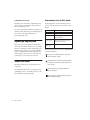
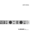
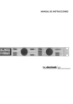
96i I/O™
Copyright
© 2006 Digidesign, a division of Avid Technology, Inc. All rights
reserved. This guide may not be duplicated in whole or in part
without the express written consent of Digidesign. Avid,
Digidesign, Avid, and Pro Tools are either trademarks or
registered trademarks of Avid Technology, Inc. in the US and
other countries. All other trademarks contained herein are the
property of their respective owners.
Product features, specifications, system requirements, and
availability are subject to change without notice.
PN 9106-18562-00 REV A 1/06
Warning
This product contains chemicals, including lead, known to the
State of California to cause cancer and birth defects or other
reproductive harm. Wash hands after handling.
Important Safety Instructions
When using electric or electronic equipment, basic precautions
should always be followed, including the following:
• Read all instructions before using this equipment.
• To avoid the risk of shock, keep this equipment away from
rain water, and other moisture. Do not use this equipment
if it is wet.
• The equipment should only be connected to the correct
rating power supply as indicated on the product.
• Do not attempt to service the equipment. There are no
user-serviceable parts inside. Please refer all servicing to
authorized Digidesign personnel.
• Any attempt to service the equipment will expose you to a
risk of electric shock, and will void the manufacturer’s
warranty.
• The product should be connected only to the correct power
supply as indicated on the product.
Communications & Safety Regulation Information
Warning!
Compliance Statement
The model 96i complies with the following standards
regulating interference and EMC:
• FCC Part 15 Class A
• EN55103 – 1, environment E4
• EN55103 – 2, environment E4
• AS/NZS 3548 Class A
• Pro Tools|HD audio interfaces need room at their sides to
maintain proper air flow and cooling.
• Do not install these units into a rack or other enclosure that
doesn't leave room on either side for the unit fans.
• Do not block the sides of the units (where fans are), or
disconnect the fan.
• If the units are racked up in a case, remove all lids, doors,
or covers before operating the units.
• Failure to do so can result in the units overheating very
quickly, which can permanently damage them.
Radio and Television Interference
This equipment has been tested and found to comply with the
limits for a Class A digital device, pursuant to Part 15 of the
FCC Rules.
Communications Statement
This equipment has been tested to comply with the limits for a
Class A digital device. Changes or modifications to this product
not authorized by Digidesign, Inc., could void the Certification
and negate your authority to operate the product. This product
was tested for CISPR compliance under conditions that
included the use of peripheral devices and shielded cables and
connectors between system components. Digidesign
recommends the use of shielded cables and connectors
between system components to reduce the possibility of
causing interference to radios, television sets, and other
electronic devices.
Safety Statement
This equipment has been tested to comply with USA and
Canadian safety certification in accordance with the
specifications of UL Standards; UL1419 and Canadian CSA
standard; CSA C22.2 No.1-M90. Digidesign Inc., has been
authorized to apply the appropriate UL & CUL mark on its
compliant equipment.
contents
Chapter 1. Introduction to the 96i I/O . . . . . . . . . . . . . . . . . . . . . . . . . . . . . . . . . . . . . . . . . 1
What’s Included . . . . . . . . . . . . . . . . . . . . . . . . . . . . . . . . . . . . . . . . . . . . . . . . . . . . . . . . . 1
System Requirements . . . . . . . . . . . . . . . . . . . . . . . . . . . . . . . . . . . . . . . . . . . . . . . . . . . . . 1
Digidesign Registration . . . . . . . . . . . . . . . . . . . . . . . . . . . . . . . . . . . . . . . . . . . . . . . . . . . . 2
About this Guide . . . . . . . . . . . . . . . . . . . . . . . . . . . . . . . . . . . . . . . . . . . . . . . . . . . . . . . . . 2
About www.digidesign.com . . . . . . . . . . . . . . . . . . . . . . . . . . . . . . . . . . . . . . . . . . . . . . . . . 3
Chapter 2. 96i I/O Hardware Overview . . . . . . . . . . . . . . . . . . . . . . . . . . . . . . . . . . . . . . . . 5
The 96i I/O Front Panel . . . . . . . . . . . . . . . . . . . . . . . . . . . . . . . . . . . . . . . . . . . . . . . . . . . . 5
96i I/O Back Panel . . . . . . . . . . . . . . . . . . . . . . . . . . . . . . . . . . . . . . . . . . . . . . . . . . . . . . . 7
Installing and Configuring the 96i I/O for Pro Tools HD . . . . . . . . . . . . . . . . . . . . . . . . . . . . . . 9
Index . . . . . . . . . . . . . . . . . . . . . . . . . . . . . . . . . . . . . . . . . . . . . . . . . . . . . . . . . . . . . . . . . . . . . 11
Contents
iii
iv
96i I/O Guide
chapter 1
Introduction to the 96i I/O
The Digidesign 96i I/O 16-input, 2-output digital audio interface features 24-bit analog-to-digital (A/D) and digital-to-analog (D/A) converters.
The 96i I/O supports sample rates up to 96 kHz
for superior dynamic range and low noise floor.
The 96i I/O is the ideal audio interface to input
multiple MIDI sound modules, samplers, synthesizers, and other sound sources into
Pro Tools|HD.
96i I/O Features
• 16 discrete input channels and two output
channels, with 4-segment LED meters on each
channel. Input and output features include:
• 16 channels of 24-bit, 96 kHz-capable analog input, with adjustable input sensitivity
• Two channels of 24-bit, 96 kHz-capable analog output, with selectable operating level
• Two channels of 24-bit, 96 kHz-capable
digital S/PDIF RCA input and output
• Loop Sync In and Out
• External Clock In and Out
What’s Included
• 96i I/O
• AC power cable
• DigiLink cable (1.5 feet [0.46m])
• BNC cable (1.5 foot [0.46m])
System Requirements
The 96i I/O requires a Digidesign-qualified
Pro Tools|HD system.
The 96i I/O can be used as the only audio interface in a Pro Tools|HD system (no other audio
interface present), or as an expansion I/O when
combined with a 192 I/O, 192 Digital I/O, 96
I/O, or other 96i I/O audio interface.
The 96i I/O cannot be used in standalone
mode (it must be used with Pro Tools).
The 96i I/O does not provide a Legacy port. For
more information on connecting the 96i I/O,
see the Pro Tools|HD Getting Started Guide.
• Expansion DigiLink port
Chapter 1: Introduction to the 96i I/O
1
Compatibility Information
Conventions Used in This Guide
Digidesign can only assure compatibility and
provide support for hardware and software it
has tested and approved.
Digidesign guides use the following conventions to indicate menu choices and key commands:
For a list of Digidesign-qualified computers, operating systems, hard drives, and third-party devices, refer to the Digidesign Web site
(www.digidesign.com).
Digidesign Registration
Review the enclosed registration information
card and follow the instructions on it to quickly
register your purchase online. Registering your
purchase is the only way you can be eligible to
receive complimentary technical support and
future upgrade offers. It is one of the most important steps you can take as a new user.
About this Guide
This guide describes the 96i I/O features and
connectors.
For complete instructions on connecting and
configuring your Pro Tools|HD system, see the
Pro Tools|HD Getting Started Guide.
Convention
Action
File > Save
Choose Save from the File menu
Control+N
While pressing the Control key,
press the N key
Control-click
While pressing the Control key,
click the mouse button
Right-click
(Windows)
Click with the right mouse button
The following symbols are used to highlight important information:
User Tips are helpful hints for getting the
most from your system.
Important Notices include information that
could affect your data or the performance of
your system.
Shortcuts show you useful keyboard or
mouse shortcuts.
Cross References point to related sections in
other Digidesign guides.
2
96i I/O Guide
About www.digidesign.com
The Digidesign Web site (www.digidesign.com)
is your best online source for information to
help you get the most out of your Pro Tools system. The following are just a few of the services
and features available.
Registration Register your purchase on-line. See
the enclosed registration form for instructions.
Support Contact Digidesign Technical Support
or Customer Service; download software updates and the latest online manuals; browse the
Compatibility documents for system requirements; search the online Answerbase or join the
worldwide Pro Tools community on the Digidesign User Conference.
Training and Education Study on your own using
courses available online or find out how you can
learn in a classroom setting at a certified
Pro Tools training center.
Products and Developers Learn about Digidesign
products; download demo software or learn
about our Development Partners and their plugins, applications, and hardware.
News and Events Get the latest news from
Digidesign or sign up for a Pro Tools demo.
To learn more about these and other resources
available from Digidesign, visit the Digidesign
Web site (www.digidesign.com).
.
Chapter 1: Introduction to the 96i I/O
3
4
96i I/O Guide
chapter 2
96i I/O Hardware Overview
This chapter describes the front and rear panel features of the 96i I/O.
See the Pro Tools|HD Getting Started Guide for complete system installation and configuration instructions. If you are adding the 96i I/O to an existing system, see the Expanded Systems Guide.
The 96i I/O Front Panel
Figure 1. 96i I/O front panel
Power Switch and LED Ring
Sample Rate LEDs
This button turns the 96i I/O on and off.
These LEDs display the current Pro Tools sample
rate: 44.1 kHz, 48 kHz, 88.2 kHz, and 96 kHz.
(The 96i I/O will go offline whenever the current Pro Tools sample rate is 176.4 kHz or
192 kHz.)
The LED ring around the power button will light
green to indicate that the unit has powered up
successfully and is connected to an active
Pro Tools|HD system. If the LED ring is orange,
the unit has power, but the computer it is connected to is shut down.
Chapter 2: 96i I/O Hardware Overview
5
Loop Master LED
The LOOP MASTER LED indicates which
Pro Tools|HD audio interface is the master
Pro Tools peripheral. Loop Master defaults to
the first Pro Tools|HD I/O connected to the
“core” Pro Tools|HD card. On Pro Tools|HD (for
PCIe) this is the Accel Core card. On
Pro Tools|HD (for PCI) this is the HD Core card.
Loop Master will always be lit in systems with a
single interface.
In expanded systems, only one Pro Tools|HD
I/O can be Loop Master at a time. When you
change the clock source to an external clock on
a particular Pro Tools|HD I/O or a SYNC I/O,
that Pro Tools|HD I/O (or SYNC I/O) will automatically become the Loop Master and all other
Pro Tools|HD I/Os in the chain will be switched
to Loop Slave mode.
Sync Mode LEDs
The SYNC MODE LEDs indicate the current
Pro Tools Clock Source and Sync mode. Choices
include the following:
INT (Internal) Indicates the 96i I/O is the
Pro Tools clock master.
DIG (Digital) Indicates the 96i I/O S/PDIF port is
providing master clock to Pro Tools.
LOOP (Loop Sync) Indicates 96i I/O is in Loop
Slave mode, and is clocking to the current Loop
Master device (which will either be another
Pro Tools|HD audio interface, a Digidesign
SYNC I/O, or equivalent device). See also “Loop
Master LED” on page 6.
EXT (External) Indicates the 96i I/O EXT
CLOCK IN port is providing master clock to
Pro Tools.
6
96i I/O Guide
For more information on Pro Tools clock options, see the Pro Tools|HD Getting Started Guide.
Input and Output LEDs and Meters
16 sets of four-segment LEDs indicate signal
level for each of the 96i I/O input channels.
These LEDs are calibrated at –42 dB, –18 dB,
–6 dB, and 0 dB, respectively, referenced to Full
Scale digital.
Full Scale digital (0 dBFS) does not always
indicate signal clipping levels. Use the onscreen meters in Pro Tools to determine
whether a signal is clipping. For more information, see the Pro Tools|HD Getting
Started Guide.
Two additional LEDs, located to the left of the
meters, indicate whether the meters display input or output levels; the meters indicate input
levels by default, and can be switched from
within the Hardware Setup dialog in Pro Tools.
96i I/O Back Panel
INPUTS 1-4
INPUTS 5-16
SW CTRL GAIN
1
2
OUTPUT
+4dBu/–12dBV
3
4
5
6
+4dBu/–10dBV
7
9
11
13
15
1
8
10
12
14
16
2
Figure 2. 96i I/O back panel
Analog Inputs
Analog Outputs
96i I/O provides 16 balanced, 1/4-inch TRS jacks
for analog audio input connections.
These are balanced, 1/4-inch TRS jacks for analog audio output connections.
Inputs 1–4 provide six stages of software-adjustable operating level sensitivity. Choices
range from –12.0 dB(V) to +4.0 dBu, with default sensitivity set to –8 dB(V).
The 96i I/O analog outputs feature 24-bit digital-to-analog converters. Output operating levels are software-switchable between +4 dBu and
–10 dB(V) operating levels.
◆
Inputs 5–16 are software-switchable between
–8 dBV and +4 dBu operating level sensitivity.
◆
The 96i I/O inputs can accommodate a wide
range of line-level devices including synthesizers, samplers, sound modules, and effects devices.
All analog inputs are balanced, and feature 24bit, 96 kHz analog-to-digital converters, with
14 dB of headroom above +4 dBu (fixed, requiring no calibration). Unbalanced connections are
supported with the use of standard 1/4-inch
mono phone plugs.
96i I/O input wiring for balanced connections
Tip
Hot (or +)
Ring
Cold (or –)
Sleeve
Ground
The 96i I/O is factory calibrated at +14 dB headroom, yielding a maximum output level of
+18 dBu when in +4 dBu operating mode.
When set to –10 dB(V) operating mode, maximum output level is +4 dBV.
Unbalanced connections are supported through
the use of standard 1/4-inch TRS mono phone
plugs.
96i I/O output wiring for balanced connections
Tip
Hot (or +)
Ring
Cold (or –)
Sleeve
Ground
Chapter 2: 96i I/O Hardware Overview
7
S/PDIF Digital In and Out
These are unbalanced RCA jacks that accept and
output a stereo S/PDIF digital data stream.
S/PDIF supports up to 24-bit audio up to the
96 kHz sample rate. S/PDIF input can be chosen
as the input source for channels 1–2 in the Hardware Setup dialog. S/PDIF output is mirrored to
analog outputs 1–2.
To maintain data integrity and minimize jitter,
use only 75-ohm coaxial cable.
Loop Sync In and Out
Loop Sync is a dedicated Pro Tools clock loop for
synchronizing multiple Pro Tools|HD peripherals together. The Loop Sync In and Out ports are
standard BNC connectors that output a 1x Loop
Sync clock signal. Loop Sync should only be
used to connect multiple Pro Tools|HD peripherals (other audio interfaces and the SYNC I/O).
Loop Sync uses a word clock signal based on
sample rates of either 44.1 kHz or 48 kHz. As
sample rate increases in the system, Loop Sync
continues to operate at a base rate of 44.1 kHz or
48 kHz (44.1 kHz for 88.2 kHz sessions, 48 kHz
for 96 kHz sessions).
For more information on Loop Sync and its connection requirements, see the Pro Tools|HD Getting Started Guide.
EXT. CLOCK In and Out
The External Clock I/O ports are standard BNC
connectors that receive and output a word clock
signal. These ports can be used to synchronize
the 96i I/O to any device that requires (or provides) word clock.
8
96i I/O Guide
External Clock In and Out are configured in the
Hardware Setup dialog.
Because the Loop Sync and Word Clock ports
pass crucial timing information, use highquality 75-ohm coaxial cables. RG59 or better quality cable is recommended.
Primary Port
The Primary Port is used to connect the 96i I/O
to your Pro Tools|HD cards, or to another
Pro Tools|HD audio interface, using a DigiLink
cable.
• When the 96i I/O is the only audio interface
in the system, the Primary Port is connected
directly to the Accel Core card (Pro Tools|HD
for PCIe systems) or HD Core card
(Pro Tools|HD for PCI systems).
• When the 96i I/O is used as an additional I/O
in an expanded Pro Tools|HD system, the
96i I/O Primary Port can be connected to an
HD Accel or HD Process card, or to the Expansion port on a 192 I/O, 192 Digital I/O, or
96 I/O. For information about connecting expanded Pro Tools|HD systems, see the Expanded Systems Guide.
Expansion Port
The Expansion Port is used to connect an additional Pro Tools|HD I/O to the 96i I/O. Using a
DigiLink cable (one is included with each
Pro Tools|HD audio interface), another 96i I/O
can be connected to the Expansion Port for an
additional 16 channels of input.
AC Power
This connector accepts a standard AC power cable. The 96i I/O is auto power-selecting (100V to
240V) and will automatically work with a standard modular cable to connect to AC power receptacles in any country.
Installing and Configuring the
96i I/O for Pro Tools HD
For complete installation and configuration instructions for the 96i I/O, see the Pro Tools|HD
Getting Started Guide.
Chapter 2: 96i I/O Hardware Overview
9
10
96i I/O Guide
index
Numerics
L
24-bit 1
96-kHz 1
Loop Master 6
Loop Master LED 6
Loop Sync
In and Out 8
B
balanced
inputs 7
base rate 8
M
C
O
Clock Source 6
outputs
analog 7
S/PDIF digital 8
word clock 8
D
DigiLink
expansion 8
Primary port 8
Meters 6
P
Power Switch and LED Ring 5
E
Expansion
DigiLink 8
port 8
External Clock
In port 8
Out port 8
H
R
registration 2
S
S/PDIF 8
Sample Rate 5
Sync Mode 6
Hardware Setup 6
U
I
unbalanced
input 7
output 7
inputs
analog 7
S/PDIF digital 8
word clock 8
W
wiring
TRS balanced input 7
TRS balanced output 7
word clock 8
Index
11