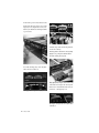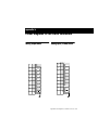
1
192 I/O
Guide
Digidesign
2001 Junipero Serra Boulevard
Daly City, CA 94014-3886 USA
tel: 650·731·6300
fax: 650·731·6399
Technical Support (USA)
650·731·6100
650·856·4275
Product Information (USA)
650·731·6102
800·333·2137
International Offices
Visit the Digidesign Web site
for contact information
Web Site
www.digidesign.com
Copyright
This guide is copyrighted ©2002 by Digidesign, a division of
Avid Technology, Inc. (hereafter “Digidesign”), with all rights
reserved. Under copyright laws, this manual may not be
duplicated in whole or in part without the written consent of
Digidesign.
DIGIDESIGN, AVID and PRO TOOLS are trademarks or
registered trademarks of Digidesign and/or Avid Technology,
Inc. All other trademarks are the property of their respective
owners.
All features and specifications subject to change without
notice.
PN 932709286-00 01/02
Important Safety Instructions
When using electric or electronic equipment, basic precautions
should always be followed, including the following:
• Read all instructions before using this equipment.
• To avoid the risk of shock, keep this equipment away from
rain water, and other moisture. Do not use this equipment
if it is wet.
• The equipment should only be connected to the correct
rating power supply as indicated on the 192 I/O.
• Do not attempt to service the equipment. There are no
user-serviceable parts inside. Please refer all servicing to
authorized Digidesign personnel.
• Any attempt to service the equipment will expose you to a
risk of electric shock, and will void the manufacturer’s
warranty.
Communications & Safety Regulation Information
Compliance Statement
The model 192 I/O complies with the following standards
regulating interference and EMC:
• FCC Part 15 Class A
• EN55103 – 1, environment E4
• EN55103 – 2, environment E4
• AS/NZS 3548 Class A
Radio and Television Interference
This equipment has been tested and found to comply with the
limits for a Class A digital device, pursuant to Part 15 of the
FCC Rules.
Communications Statement
This equipment has been tested to comply with the limits for a
Class A digital device. Changes or modifications to this
192 I/O not authorized by Digidesign, Inc., could void the
Certification and negate your authority to operate the 192 I/O.
This 192 I/O was tested for CISPR compliance under
conditions that included the use of peripheral devices and
shielded cables and connectors between system components.
Digidesign recommends the use of shielded cables and
connectors between system components to reduce the
possibility of causing interference to radios, television sets,
and other electronic devices.
Safety Statement
This equipment has been tested to comply with USA and
Canadian safety certification in accordance with the
specifications of UL Standards; UL1419 and Canadian CSA
standard; CSA C22.2 No.1-M90. Digidesign Inc., has been
authorized to apply the appropriate UL & CUL mark on its
compliant equipment.
Warning!
• HD audio interfaces need room at their sides to maintain
proper air flow and cooling.
• Do not install these units into a rack or other enclosure that
doesn't leave room on either side for the unit fans.
• Do not block the sides of the units (where fans are), or
disconnect the fan.
• If the units are racked up in a case, remove all lids, doors,
or covers before operating the units.
• Failure to do so can result in the units overheating very
quickly, which can permanently damage them.
contents
Chapter 1. Introduction to the 192 I/O . . . . . . . . . . . . . . . . . . . . . . . . . . . . . . . . . . . . . . . . 1
What’s Included . . . . . . . . . . . . . . . . . . . . . . . . . . . . . . . . . . . . . . . . . . . . . . . . . . . . . . . . . 1
System Requirements . . . . . . . . . . . . . . . . . . . . . . . . . . . . . . . . . . . . . . . . . . . . . . . . . . . . . 1
About This Guide . . . . . . . . . . . . . . . . . . . . . . . . . . . . . . . . . . . . . . . . . . . . . . . . . . . . . . . . . 2
Chapter 2. 192 I/O Overview . . . . . . . . . . . . . . . . . . . . . . . . . . . . . . . . . . . . . . . . . . . . . . . . . 3
192 I/O Front Panel . . . . . . . . . . . . . . . . . . . . . . . . . . . . . . . . . . . . . . . . . . . . . . . . . . . . . . 3
192 I/O Back Panel . . . . . . . . . . . . . . . . . . . . . . . . . . . . . . . . . . . . . . . . . . . . . . . . . . . . . . 5
DigiLink Connections . . . . . . . . . . . . . . . . . . . . . . . . . . . . . . . . . . . . . . . . . . . . . . . . . . . . . . 9
Chapter 3. Installation Overview . . . . . . . . . . . . . . . . . . . . . . . . . . . . . . . . . . . . . . . . . . . . . 11
Checking Installation . . . . . . . . . . . . . . . . . . . . . . . . . . . . . . . . . . . . . . . . . . . . . . . . . . . . . 12
Powering Up Your System . . . . . . . . . . . . . . . . . . . . . . . . . . . . . . . . . . . . . . . . . . . . . . . . . 13
Making Signal Connections to the 192 I/O . . . . . . . . . . . . . . . . . . . . . . . . . . . . . . . . . . . . . 13
Example Studio Setup with a Mixing Console . . . . . . . . . . . . . . . . . . . . . . . . . . . . . . . . . . . . 14
Example Studio Setup without a Mixing Console . . . . . . . . . . . . . . . . . . . . . . . . . . . . . . . . . 15
Hardware Setup . . . . . . . . . . . . . . . . . . . . . . . . . . . . . . . . . . . . . . . . . . . . . . . . . . . . . . . . 16
Multiple Outputs . . . . . . . . . . . . . . . . . . . . . . . . . . . . . . . . . . . . . . . . . . . . . . . . . . . . . . . . 20
Setting Operating Levels . . . . . . . . . . . . . . . . . . . . . . . . . . . . . . . . . . . . . . . . . . . . . . . . . . 21
Soft Clip Limiting . . . . . . . . . . . . . . . . . . . . . . . . . . . . . . . . . . . . . . . . . . . . . . . . . . . . . . . 23
Synchronization Mode and Clock Source . . . . . . . . . . . . . . . . . . . . . . . . . . . . . . . . . . . . . . . 23
Appendix A. Adding or Removing I/O Cards . . . . . . . . . . . . . . . . . . . . . . . . . . . . . . . . . . . 27
Installing an I/O Card . . . . . . . . . . . . . . . . . . . . . . . . . . . . . . . . . . . . . . . . . . . . . . . . . . . . 27
Removing an I/O Card . . . . . . . . . . . . . . . . . . . . . . . . . . . . . . . . . . . . . . . . . . . . . . . . . . . . 30
Contents
iii
Appendix B. Pinout Diagrams for the DB-25 Connectors . . . . . . . . . . . . . . . . . . . . . . . 33
Analog Output DB-25 . . . . . . . . . . . . . . . . . . . . . . . . . . . . . . . . . . . . . . . . . . . . . . . . . . . . 33
Analog Input (+4 dBu) DB-25 . . . . . . . . . . . . . . . . . . . . . . . . . . . . . . . . . . . . . . . . . . . . . . . 33
Analog Input (–10dBV) DB-25 . . . . . . . . . . . . . . . . . . . . . . . . . . . . . . . . . . . . . . . . . . . . . . 34
AES/EBU DB-25 . . . . . . . . . . . . . . . . . . . . . . . . . . . . . . . . . . . . . . . . . . . . . . . . . . . . . . . . 34
TDIF DB-25 . . . . . . . . . . . . . . . . . . . . . . . . . . . . . . . . . . . . . . . . . . . . . . . . . . . . . . . . . . . 35
Index . . . . . . . . . . . . . . . . . . . . . . . . . . . . . . . . . . . . . . . . . . . . . . . . . . . . . . . . . . . . . . . . . . . . . 37
iv
192 I/O Guide
chapter 1
Introduction to the 192 I/O
The Digidesign 192 I/O is a 16-channel digital
audio interface for use in a Pro Tools|HD system.
Featuring 24-bit analog-to-digital (A/D) and digital-to-analog (D/A) converters, the 192 I/O supports sampling rates of up to 192 kHz for superior dynamic range and low noise floor.
192 I/O Features
• 16 discrete channels of input and output,
with 4-segment LED Meters to monitor input
and output on each channel. Input and Output channels can include:
• Eight channels of 24-bit D/A and A/D converters for superior analog input and output at sampling rates of 44.1 kHz, 48 kHz,
88.2 kHz, 96 kHz, 176.4 kHz, and 192 kHz
• Ten channels of 24-bit-supported AES/EBU
I/O, eight channels of which support sampling rates of up to 192 kHz
• Sixteen channels of Optical I/O, through
two pairs of Lightpipe (ADAT) connectors;
one pair of optical ports can be switched to
two channels of optical S/PDIF I/O
• Two 24-bit-capable S/PDIF I/O supporting
sample rates of up to 96 kHz
• Real-time sample rate conversion on inputs of
eight channels of either AES/EBU, Optical, or
TDIF.
• Simultaneous use of up to eight 192 I/O units
is supported, for a maximum of 96 channels
of I/O at 96 kHz.
• Legacy Port for Digidesign MIX-series audio
interfaces.
• Optional addition of cards to expand analog
or digital I/O.
What’s Included
• 192 I/O with power cable
• This guide
• DigiLink cable (1.5ft. [0.46m])
• BNC cable (1.5ft. [0.46m])
System Requirements
The Digidesign 192 I/O requires:
• A Pro Tools|HD system on a qualified Macintosh OS or Windows CPU
• Pro Tools software, version 5.3 or higher
• A monitoring system (mixer, amplifier, speakers, or headphones)
• Word Clock input and output for synchronizing 192 I/O with external Word Clock or 256x
(Slave Clock) devices.
Chapter 1: Introduction to the 192 I/O
1
About This Guide
This guide provides a basic overview of the
192 I/O’s features and functionality.
Complete instructions for connecting and configuring your Pro Tools|HD system are located
in the Getting Started with HD Guide.
For additional information about using
Pro Tools software to route your interface inputs
and outputs to Pro Tools inputs and outputs, see
the Pro Tools Reference Guide.
Conventions Used in This Guide
Digidesign guides use the following conventions to indicate menu choices and key commands:
Convention
Action
File > Save Session
Choose Save Session
from the File menu
Control+N
Hold down the Control
key and press the N key
Option-click
Hold down the Option key
and click the mouse button
The following symbols are used to highlight important information:
User Tips are helpful hints for getting the
most from your system.
Important Notices include information that
could affect your session data or the performance of your system.
Cross References point to related sections in
this and other Digidesign Guides.
2
192 I/O Guide
chapter 2
192 I/O Overview
192 I/O Front Panel
The 192 I/O has the following front panel features:
192 I/O Front Panel
Power Switch and LED Ring
Sample Rate
This button turns the 192 I/O on and off.
These LEDs display the current sample rate of
the 192 I/O internal crystal oscillator, that can
be 44.1 kHz, 48 kHz, 88.2 kHz, 96 kHz,
176.4 kHz, or 192 kHz. The sample rate can be
set when you create a new session, or in the
Hardware Setup or Playback Engine dialogs if no
session is open.
The LED ring around the power button will light
green to indicate that the unit has powered up
successfully and is connected to an active HD
system. If the LED ring is orange, the unit has
power, but the computer it is connected to is
shut down.
Loop Master LED
The LOOP MASTER LED indicates which HD audio interface is the master Pro Tools peripheral.
Loop Master defaults to the first HD I/O connected to the HD Core card. Loop Master will always be lit with a single interface.
Chapter 2: 192 I/O Overview
3
Sync Mode LEDs
The SYNC MODE LEDs indicate different clock
source modes. Synchronization mode LEDs reflect the Clock Source choice in Pro Tools.
Only one HD I/O can be Loop Master at a time.
When you change the clock source to an external clock on a particular HD I/O, that HD I/O
will automatically become the Loop Master and
all other HD I/Os in the chain will be switched
to Loop Slave mode. The Loop Master LED will
be continuously lit on the current Loop Master
peripheral only, and unlit on all other peripherals.
For more information, see “Synchronization
Mode and Clock Source” on page 23.
Meters
These four-segment LEDs indicate signal level
for each of the sixteen channels. The top row of
meters indicates input levels, and the bottom
row shows output levels. These meters are calibrated at –42 dB, –18 dB, –6 dB, and 0 dB, respectively.
Note that 0 dB is not to be confused with
clipping; use the on-screen meters in
Pro Tools to determine whether a signal is
clipping. See the Pro Tools|HD Reference
Guide.
4
192 I/O Guide
192 I/O Back Panel
Bay 1: Analog In Card
Bay 3: Digital I/O Card
Enclosure
Empty Bay for Optional Card
Bay 2: Analog Out Card
192 I/O Rear Panel
Although the 192 I/O is a 16-channel interface,
it has up to 50 inputs and outputs that can be assigned to Pro Tools channels.
Installing an optional card provides even more
I/O (depending on the card, you will get a total
of 58, 66, or 74 inputs and outputs). See
Appendix A, “Adding or Removing I/O Cards.”
Input and Output Cards
The 192 I/O features four bays for I/O cards.
Bays 1–3 contain Analog In, Analog Out, and
Digital I/O cards, respectively. The fourth bay is
an expansion bay, for which you can purchase
an additional audio card of your choice.
Input is provided through two discrete DB–25
connectors, one for +4 and one for –10 operation. See Appendix B, “Pinout Diagrams for the
DB-25 Connectors.”
+4 dBu Balanced
This DB–25 connector provides eight balanced
input channels at +4 dBu nominal operating
levels.
–10 dBV Balanced
This DB–25 connector provides eight balanced
input channels at –10 dBV nominal operating
levels.
Analog Input Options
Analog Input
This section contains connectors for eight channels of analog audio input with 24-bit, 192 kHz
A/D converters. Two dedicated Input Trims are
provided for each input channel, and there is a
soft-clip limiter function that helps to avoid digital clipping. See “Input Trims” on page 6, and
“Soft Clip Limiting” on page 23.
For each channel, you can select input level and
Input Trim settings from within the Hardware
Setup dialog.
When you select an operating level for each input, you are simultaneously selecting which input the signal enters through. This lets you connect sources at both operating levels that are
selectable from within Pro Tools.
Chapter 2: 192 I/O Overview
5
Input Trims
Digital I/O
Two dedicated Input Trims per analog input
channel provide further calibration options and
flexibility. Depending on how you utilize the
two DB–25 input ports, you can use the A and B
trim settings for numerous applications. See “Input Trims” on page 23.
This section contains connectors for eight channels each of AES/EBU I/O, TDIF I/O, and Optical
(ADAT) I/O. Only one digital format can be used
at a time.
Analog Output
This section contains a single DB–25 connector
and Output Trims for eight channels of analog
audio output. These balanced outputs operate at
+4 dBu levels. See Appendix B, “Pinout Diagrams for the DB-25 Connectors.”
For –10 dBV gear, a special DigiSnake cable
(sold separately) is available. If you want to
make your own cable, be sure to use in-line
transformers or resistor networks to properly
pad the +4 dBu output to –10 dBV levels.
See “About Output Levels” on page 21.
Output Trims
The output trims below the DB–25 connector
are used to individually calibrate each channel’s
output level.
Two sets of Output Trims are provided for each
channel allowing you to store a second set of
headroom values. This allows you to match two
different headroom values for either input connector.
Most consumer electronics operate at
–10 dBV levels, and may not feature balanced inputs and outputs. You can connect
–10 dBV signals to the –10 dBV inputs, but
you will need to make sure that the negative
terminals are not connected.
See “Output Trims” on page 22.
6
192 I/O Guide
The inputs on the Digital I/O Card feature realtime sample rate conversion. For example, you
can stream audio with a sample rate of 44.1 kHz
into a 96 kHz session.
See “Digital Format Settings and Sample Rate
Conversion” on page 19.
AES/EBU DB–25 connectors for eight channels
of AES/EBU input and output. Each of the paired
channels is a balanced three-conductor signal,
and supports 192 kHz sample rates in dual-wire
mode. Dual-wire mode uses two of 192 I/O’s
physical I/O channels of AES/EBU I/O to carry
each single stream of 192 kHz audio. Therefore,
only four simultaneous channels of AES/EBU
I/O are available at 192 kHz.
TDIF DB–25 connectors for eight channels of
TDIF input and output. Conforms to standard
eight-channel TDIF pinouts.
See Appendix B, “Pinout Diagrams for the DB25 Connectors.”
Optical (ADAT) Dedicated, eight-channel 24-bit
capable Optical port. Using real-time sample
rate conversion, these inputs will accept up to
48 kHz sample rates and convert them to a
Pro Tools session running at up to 192 kHz.
These outputs will only output at sampling rates
of up to 48 kHz. Unlike the Optical port located
on the enclosure, this Optical (ADAT) port is not
switchable to Optical S/PDIF.
Enclosure Connectors
Optical (ADAT) [Encl]
The right half of the back panel of 192 I/O features a set of non-removable connectors that are
mounted to the enclosure.
These are Optical ports that accept up to eight
channels of Optical (ADAT) input and output,
or two channels (stereo) optical S/PDIF input
and output. Optical (ADAT) mode supports
sample rates up to 48 kHz. In TOS-Link mode,
supports two-channel Optical input and output
at sample rates up to 96 kHz. This port does not
feature real-time sample rate conversion.
These connectors feature two additional channels of AES/EBU I/O and another eight channels
of Optical I/O. These ports are hardwired to the
192 I/O chassis and appear on-screen in the
Pro Tools pop-up menus as AES/EBU [Encl], and
Optical (ADAT) [Encl]. The reference to the enclosure [Encl] differentiates the chassismounted ports from the I/O of the same types
on the Digital I/O Card.
Also mounted on the enclosure are two channels of S/PDIF I/O on RCA connectors, synchronization ports and connectors for installing 192
I/) to your HD system and attaching other
Digidesign I/Os.
AES/EBU [Encl]
These are balanced, three-conductor XLR connectors that accept and output a stereo, 24-bit
AES/EBU digital data stream. These two ports
support up to 96 kHz sample rates. The enclosure ports do not support dual-wire mode (required for 176.4 kHz and higher sample rates),
or provide real-time sample rate conversion (use
the ports on the Digital I/O card for these features).
About Lightpipe-Compatible Devices
Lightpipe is an industry standard, eight-channel
optical digital audio connection created by Alesis. Lightpipe is found on many devices, including Optical (ADAT) decks, modular digital multitracks (MDMs), sound cards, A/D or D/A
converters, and digital consoles.
LOOP SYNC In and Out
Loop Sync is a dedicated clock loop for synchronizing multiple HD-series interfaces together.
Loop Sync uses a word clock signal based on
sampling rates of either 44.1 kHz or 48 kHz. As
sample rates increase in the system, Loop Sync
continues to operate at a base rate of 44.1 kHz or
48 kHz, depending upon the higher rate.
The Loop Sync In and Out ports are standard
BNC connectors that output a 1x Loop Sync
clock signal. Loop Sync should only be used to
chain multiple HD-series peripherals together.
S/PDIF Stereo I/O
EXT. CLOCK In and Out
These are unbalanced, two-conductor RCA jacks
that accept and output a stereo S/PDIF digital
data stream. S/PDIF supports up to 24-bit audio,
at sample rates up to 96 kHz.
The External Clock I/O ports are standard BNC
connectors that receive and output a word clock
signal. These ports can be used to synchronize
the 192 I/O to any device that requires (or provides) word clock.
Chapter 2: 192 I/O Overview
7
The External Clock In port is configured by your
choice for Clock Source in the Hardware Setup
dialog. The External Clock Out is configured using the External Clock Out selector in the Hardware Setup dialog.
Because crucial timing data is passed
through the Loop Sync and Word Clock ports,
you should use high-quality, 75-ohm RG–59
cables for making connections.
AC Power
This connector accepts a standard AC power cable. The 192 I/O is auto power-selecting (100V
to 240V) and will automatically work with a
standard modular cable to connect to AC power
receptacles in any country.
Primary DigiLink
The Primary port is where the DigiLink cable
connects from your HD Core or Process card to
the 192 I/O. The Primary DigiLink port sends
and receives all 32 I/O channels to and from the
HD Core or Process card. As the 192 I/O is a 16channel only device, channels 17–32 are passed
through to the Expansion or Legacy port.
Legacy Port
This port is used to connect MIX-series Digidesign audio interfaces to 192 I/O. You can connect two eight-channel interfaces (such as the
888|24 or 882|20) or a single sixteen-channel interface (1622 I/O, 24-bit ADAT Bridge I/O, or the
original ADAT Bridge I/O) for expanded input
and output options, using their original cables.
When the Legacy port has been activated from
within Pro Tools, your MIX-series I/O will appear as channels 17–32 in the Pro Tools mixer.
To connect HD or Legacy audio interfaces, refer
to the Getting Started With HD Guide.
Legacy and Expansion Peripheral Port
Limitations
Because both the Legacy port and the Expansion
port use channels 17–32, you can only use one
at a time.
To select the Legacy or Expansion ports, refer to
the Pro Tools Reference Guide.
The Legacy port is not available in any session in
which the sample rate is set for higher than
48 kHz.
Expansion DigiLink
Accessory Port
The Expansion port is where the DigiLink cable
connects an additional 192 I/O or 96 I/O to
your base, or primary, 192 I/O. This port passes
channels 17–32 to the secondary, or expansion,
I/O.
8
192 I/O Guide
This port is not supported at this time.
DigiLink Connections
DigiLink cables make the vital connection between your HD Core or HD Process card and
your HD I/Os. DigiLink cables are also used to
interconnect multiple HD I/Os together to expand total system I/O.
DigiLink Length Specifications
There are five different lengths of DigiLink cables:
• The 18’ (0.46m) cable is included with each
HD I/O, designed for daisy-chaining multiple
HD audio interfaces.
• The 12’ (3.6m) cable included with each HD
Core, designed for connecting the Core card
to an HD I/O.
• 25’ (7.62m) cable is the same length as ProControl and Control|25 breakout cables.
• 50’ (15.25m) cable (sold separately). This is
the maximum length supported for 192 kHz
sessions.
• 100’ (30.5m) maximum cable length (sold
separately), that only supports sample rates of
96 kHz or lower.
Chapter 2: 192 I/O Overview
9
10
192 I/O Guide
chapter 3
Installation Overview
Complete instructions for connecting and configuring your Pro Tools|HD system are located
in the Getting Started with HD Guide. If you are
connecting the 192 I/O to a new Pro Tools|HD
system, refer to that guide now.
If you are adding the 192 I/O to an existing
Pro Tools|HD system, you can probably use just
the instructions here in this chapter of your
192 I/O Guide. Additional information can always be found in the Getting Started with HD
Guide, and the Expanded Systems Guide.
Guidelines for DigiLink Connections
Whenever a system includes at least one
192 I/O, a 192 I/O should be the primary audio
interface, with any additional 192 I/O interfaces
connected next. Following any and all 192 I/Os,
any and all 96 I/Os should be connected. For
Legacy peripherals, see “Legacy Port” on page 8.
For additional details on the ordering of audio
interfaces in an expanded system, see the Expanded Systems Guide.
To connect the 192 I/O to an existing HD System:
Connecting the 192 I/O
to an Existing HD System
If you are adding this interface to an existing Pro
Tools|HD system, follow these guidelines:
Turn off your computer, hardware interfaces,
monitoring system, hard drives, and peripherals. Making connections while power is on
can damage your system.
DigiLink Cable Connections
The DigiLink cable provided with the 192 I/O is
18” long. If you need a 12' or longer DigiLink cable to connect to the HD Process card, you must
purchase DigiLink cables separately.
■ If the existing system contains a single 96 I/O
you will need to disconnect the 96 I/O from the
HD Core card, then connect the 192 I/O directly
to the primary HD Core card, followed by the
96 I/O. Connect the DigiLink cable from the DigiLink port on the primary HD Core card to the
Primary port on the 192 I/O. Connect another
DigiLink cable from the Expansion port on the
192 I/O to the Primary port on the 96 I/O.
The 96 I/O does not support 192 kHz, and
you will not be able to run a session at
192 kHz unless the 192 I/O is the first interface connected to the HD Core card.
Chapter 3: Installation Overview
11
If the existing system contains a single
192 I/O, you can connect your 192 I/O directly
to the first HD Process card or through the Expansion port of your 192 I/O. Connect the DigiLink cable from the Primary port of the new
192 I/O to either the Expansion port on the existing 192 I/O or the DigiLink port on the HD
Process card.
■
If you already have two 192 I/Os connected to
your HD Core, connect the new 192 I/O directly
to the first HD Process card. Connect the DigiLink cable from the Primary port of the new
192 I/O to the DigiLink port on the HD Process
card.
Checking Installation
This section explains how to quickly check that
your installation was successful.
To check installation using DigiTest:
1 Start up your computer (see “Powering Up
Your System” on page 13).
■
2 Launch DigiTest.
3 Ensure that any and all HD cards and HD I/Os
are identified properly. If not, see the Getting
Started with HD Guide.
4 When finished, quit DigiTest and restart.
Loop Sync Connections with BNC Cable
To check or reconfigure I/O:
To connect Loop Sync between two interfaces:
Connect the BNC cable from the Loop Sync
Out of the primary 192 I/O to the Loop Sync In
of the new 192 I/O. Connect the Loop Sync Out
from the new 192 I/O to the Loop Sync In of the
primary 192 I/O.
■
To connect the 192 I/O into a Loop Sync chain:
Connect the new 192 I/O Loop Sync In and
Out ports to properly place the new interface in
the Loop Sync chain. See the Getting Started with
HD Guide for more information.
■
12
192 I/O Guide
1 Launch Pro Tools and choose Setup > Hardware Setup.
2 Use the Identify button to verify that your
newly-added 192 I/O has been properly identified. Select each 192 I/O in the Peripherals list,
and click on the Identify radio box in the lower
left corner of the Hardware Setup dialog to illuminate all of the LEDs on the front panel. This
will clearly demonstrate which 192 I/O you
have selected in the Peripherals list.
3 If you encounter any difficulties, delete the
DigiSetup file (located in the System Folder/Preferences), power down the computer completely,
and turn off all interfaces. Then turn the power
back on all interfaces and boot the computer.
See “Powering Up Your System” on page 13 for
more information.
Powering Up Your System
In order for Pro Tools to communicate properly
with audio interfaces and other peripherals, it is
important that you start up and shut down your
system in the following order:
Power up your system in this order:
1 Turn on your Pro Tools hard drives.
2 Turn on synchronization or other MIDI peripherals or interfaces.
3 Turn on your 192 I/O and any other Pro Tools
audio interfaces. On power up, the status LEDs
will flash. Wait at least fifteen seconds for the
192 I/O to initialize, and the status LEDs to stop
blinking and stay lit on any and all audio interfaces. If properly connected, the ring around the
power switch will be orange while the computer
is powered down.
Making Signal Connections to
the 192 I/O
Depending on how you plan to use the 192 I/O,
the way you connect it to your studio will vary.
Setting Up Your Studio
The following diagrams provide general suggestions for connecting studio gear to your system.
Figure 1 on page 14 illustrates a studio setup
with the 192 I/O connected to a mixing console,
with effects and other gear routed into the console as well.
Figure 2 on page 15 diagram shows a setup without a mixer, where effects and monitoring gear
are connected directly to the 192 I/O.
4 Turn on your computer. When the computer
boots, all power LED rings on HD I/O should
switch to green. This signifies that the HD I/Os
are properly connected to HD cards or other HD
I/Os in your system.
MIX-series audio interfaces will not be available
until they have been made active in the Hardware Setup dialog. See the Getting Started with
HD Guide for info.
Power down your system in this order:
1 Quit Pro Tools.
2 Shut down the computer.
3 Power off your audio interfaces.
4 Turn off any synchronization, MIDI, or other
peripherals or interfaces.
5 Turn off your drives.
Chapter 3: Installation Overview
13
Example Studio Setup with a
Mixing Console
Optical
in/out
to ADAT
Digital Inputs/Outputs
To DAT Recorder
DAT Recorder
Analog
Audio
Inputs
Analog
Audio
Outputs
Digital Effects Device
(set to external sync)
Effects Devices
Optional DigiSnakes
(DB–25 to XLR or 1/4")
Channel
Outputs
Tape Returns
or Inputs
Instruments
Connected to Console
Figure 1. Example Studio Setup with a Mixing Console
14
192 I/O Guide
Power Amp
and Speakers
Example Studio Setup
without a Mixing Console
ADAT
Mic, Preamp,
Direct Box, Synth, etc.
Optical
in/out
to ADAT
Analog
Audio
Inputs
Digital Inputs/Outputs
To DAT Recorder
DAT Recorder
Analog
Audio
Outputs
Analog
Audio
ins/outs
Optional DigiSnakes
(DB–25 to XLR or 1/4")
Digital Effects Device
(set to external sync)
Other Effects Devices
Power Amp
and Speakers
Figure 2. Example Studio Setup without a Mixing Console
Chapter 3: Installation Overview
15
Hardware Setup
The Hardware Setup dialog shows you a list of
all audio interfaces in the system as well as I/O
routing and clock selections for your HD I/Os.
The Hardware Setup also allows you to set special options unique to the 192 I/O.
Hardware Setup automatically configures itself
to default settings for each HD-series card and
peripheral it detects. The Hardware Setup dialog
also lets you change default settings, and configure expansion audio interfaces (including Legacy peripherals).
Configuring Hardware Setup
(Audio Interfaces)
The Main tab of the Hardware Setup dialog is
where you define what physical ports are routed
to Pro Tools input and output channels. Think
of this window as a patchbay that allows you to
route any of the physical inputs or outputs to
Pro Tools mixer inputs and outputs.
The Main tab also provides controls for session
Sample Rate, synchronization settings, and to
define whether Expansion port or Legacy port
peripherals are active. Sample Rate can only be
changed when there is no session open.
Additional tabs are available to configure other
parameters on each audio interface (such as setting operating levels).
You must select an HD I/O from the Peripherals
column in order to change settings on a specific
interface in expanded I/O system.
Hardware Setup dialog with Main tab selected
16
192 I/O Guide
To configure audio interfaces:
1 In Pro Tools, choose Setups > Hardware.
2 From the Peripherals list, select your 192 I/O
or any audio interface you would like to adjust.
If you only have a single 192 I/O in your system,
it will already be selected by default.
3 Make sure Main tab is chosen.
When the Hardware Setup dialog is open,
the Left and Right arrows scroll through the
tabs; the Up and Down arrows scroll
through the Peripherals list.
4 From the Digital Format radio buttons, select
the desired format for the enclosure digital I/O
of your choice. Choices include: AES/EBU,
S/PDIF, and Optical (S/PDIF). Selecting Optical
(S/PDIF) resets the Optical I/O port to two channels of S/PDIF, or TOS-Link, supporting up to 96
kHz. When Optical (S/PDIF) is not selected, this
port defaults to eight channels of
Optical (ADAT) I/O.
8 From the Input and Output channel pop-up
menus, select the physical ports (such as Analog
1–2, Optical 5–6, and so on) that will be routed
to the Pro Tools input and output channels (Ch
1–2, 3–4, and so on). You can select default settings at any time by pressing the Set To Default
button on the lower edge of the Hardware Setup
dialog.
Certain functions and paths will be greyed-out
as a result of other selections. For example, the
Optical 1–8 channels will not be available for
session rates of 88.2 kHz or higher.
To differentiate inputs and outputs of the same
digital format, they are labelled differently in
the input and output channel pop-up menus.
For example, the stereo AES/EBU inputs and
outputs that are mounted on the 192 I/O enclosure are identified as AES/EBU [Encl]; the eight
channels of AES/EBU I/O that come on the Digital I/O card are listed as AES/EBU 1–2, AES/EBU
3–4, and so on.
5 From the Clock Source pop-up menu, select
the appropriate clock source for the system. In
most non-synchronized cases, you will use Internal. See “Synchronization Mode and Clock
Source” on page 23 for more information about
non-internal clock settings.
6 From the Ext. Clock Output pop-up menu, se-
lect the appropriate clock source to feed to devices attached to your I/O. Slave Clock is
automatically selected when a Legacy peripheral
has been declared. See “Clock Source and Loop
Master” on page 24.
7 For S/PDIF compatibility with Tascam DA30
DAT recorders, click on the Tascam button, under S/PDIF Format.
Chapter 3: Installation Overview
17
Analog Input Settings
Analog Output Settings
To configure analog input options:
To configure analog output options:
■
Click on the Analog In tab and select the Reference Input Level (+4 dBu or –10 dBV, which
also determines which port is used on the rear of
the 192 I/O), Input Trim settings (A or B), and
Soft Clip limiter function, respectively, on each
channel. See “Setting Operating Levels” on
page 21 and “Soft Clip Limiting” on page 23.
■ Click on the Analog Out tab and select which
trim setting will be used for the individual analog outputs. The default is A and comes from the
factory set for a headroom value of 18 dB. The
B trim comes from the factory with 20 dB of
headroom. See “Setting Operating Levels” on
page 21.
Hardware Setup dialog with Analog In tab selected
Hardware Setup dialog with Analog Out tab selected
Refer to “192 I/O Back Panel” on page 5 to locate the different ports and connectors described in this section.
18
192 I/O Guide
While there are two discrete sets of inputs at
the reference levels of –10 dBV and +4 dBu,
there is only one set of outputs, set at a reference level of +4 dBu.
Digital Format Settings and
Sample Rate Conversion
The following example shows how to configure an
HD system with one 192 I/O and one 96 I/O in the
Hardware Setup dialog:
To configure digital formats and sample rate
conversion:
1 From the Peripherals list, choose the 192 I/O
(which should be your primary I/O). By default,
the Main tab will be selected, and options and
controls for the selected I/O will be available.
The expansion interface connected to the primary I/O will appear below it in the Peripherals
column.
1 Click on the Digital tab and select Input Format (AES/EBU, ADAT, or TDIF).
2 Enable real-time Sample Rate Conversion by
selecting channel pairs (1–2, 3–4, 5–6, 7–8) in
the SR Conversion box on the Digital tab.
2 In the Main page, ensure that Expansion I/O is
At session sample rates above 48 kHz, sample rate conversion for the TDIF and Optical
(ADAT) inputs on the Digital I/O card is
automatically enabled on all eight inputs of
the selected format.
selected under Port Settings.This is the default.
3 From the Peripherals list, select your secondary I/O (in this case, the 96 I/O).
4 Configure the Main page and other settings
and options for the secondary peripheral.
Legacy I/O Setup
Repeat the above steps for any Legacy I/Os (such
as 888|24 I/O) connected to the first I/O, then
second, and so on. Before you can configure a
Legacy I/O, however, it must first be connected
and initialized in Hardware Setup.
To connect and initialize Legacy I/Os:
Hardware Setup dialog with Digital tab selected
To configure additional interfaces:
Repeat the above steps for additional HD-series I/O in the Peripherals list. To configure the
Main tab of a secondary HD peripheral attached
to a primary HD I/O, you must first choose the
I/O in the Peripherals list.
■
1 Make sure the entire HD system is powered
down before connecting your Legacy I/O.
2 Connect the slave clock cable that came with
your MIX-series peripheral to the Ext. Clock
Output of the HD I/O and the Slave Clock In
port on the back of your MIX-series peripheral.
3 Connect your Legacy I/O with its MIX-series
cable to the Legacy port on the HD peripheral.
4 Power up your system and launch Pro Tools.
5 Before you turn on and configure your Legacy
I/O, turn down the volume on your monitoring
system. Very loud digital noise may be emitted
before the Legacy I/O is initialized.
Chapter 3: Installation Overview
19
6 Turn on your Legacy I/O.
Configuring I/O Setup
7 Wait for the Legacy I/O to initialize. While the
I/O Setup provides tools to label and map
Pro Tools input, output, insert, and bus signal
paths.
Legacy I/O is initializing, some of its LEDs will
flash.
To configure Legacy I/Os:
1 Power up the rest of your gear (see “Powering
Up Your System” on page 13) and launch ProTools.
2 Choose Setup > Hardware Setup.
In addition, the I/O Setup dialog, like the Main
tab of Hardware Setup, provides controls for
routing the physical ports on your I/O peripheral to Pro Tools input and output channels.
Refer to the Pro Tools Reference Guide for
more information on setting up I/O paths.
3 From the Peripherals list, select the primary
I/O.
4 From the Main tab, select the Legacy I/O button in the Port Settings.
5 In the Peripherals list, select the first line, la-
beled”> <No Interface>,” directly below your
I/O in the Peripherals list. A pop-up menu will
appear with a list of interfaces to choose from.
6 From the Interface pop-up menu, select your
Legacy I/O.
7 After the Hardware Setup dialog updates,
choose your I/O in the Peripherals list.
The I/O is automatically selected in the Peripherals list, and is labelled HD Core #1, Port A.
Configure the peripheral's options as available
in Hardware Setup, then close the Hardware
Setup dialog.
Multiple Outputs
Multiple outputs from your 192 I/O can be assigned from a single Pro Tools mixer output.
This type of mirroring is useful when laying
back material in multiple formats.
For example, if you look at the default settings
for the Hardware Setup dialog, you will see on
the Main tab that there is a “+” sign in front of
the Output assignment for channels 1 and 2.
Click the Default button on the lower edge of
the Hardware Setup dialog if you want to reset
your assignments to the factory defaults.
This basic configuration routes Pro Tools channels 1 and 2 to Analog Outputs 1 and 2, and the
“+” symbol means that there are multiple outputs for channels 1 and 2.
Select the pop-up menu for channels 1 and 2 in
the Output column of the Main tab, you will see
that the Digital [Encl] (AES/EBU, S/PDIF) outputs are also checked, which means that those
ports are outputting Pro Tools channels 1 and 2
as well. In fact, the Digital [Encl] (AES/EBU,
S/PDIF) outputs always mirror each other.
20
192 I/O Guide
This allows you, for example, to quickly make a
single output assignment in a Pro Tools session
(A 1-2), which is then mirrored to the analog
outputs for your monitor system, DAT Deck,
and/or a S/PDIF device, with no extra load on
your Pro Tools system.
Setting Operating Levels
There are specific windows within the Hardware
Setup dialog in which to make I/O settings specific to your 192 I/O. These include setting input and output operating levels.
You can multi-assign any available 192 I/O outputs in the Hardware Setup dialog.
To route Pro Tools channels to multiple 192 I/O
outputs:
1 In the Hardware Setup dialog, click the pop-up
for the Pro Tools output pair you wish to multiassign (for example, 1–2, 3–4, 15–16). By default, all pairs are assigned to a 192 I/O output
pair, except for Analog Outputs 1–2 which are
by default mirrored to the two-channel
Digital [Encl] pairs.
Hardware Setup dialog with 192 I/O as the Primary
audio interface with Default settings
2 Select one of the outputs to which you want
to route the output from Pro Tools.
Choosing +4 dBu or –10 dBV
Operating Levels
3 While pressing Ctrl, select each additional
The 192 I/O features two DB–25 breakout connectors for two sets of eight inputs each, at
+4 dBu and –10 dBV respectively.
output destination.
Selecting multiple output formats does not affect time slot count. The multiplexing of audio
is done in the peripheral rather than in software
or the computer.
There are no –10 dBV outputs, however; analog
outputs break out from a single DB–25 output at
+4 dBu operating levels.
About Output Levels
It is important that you determine which line
level is appropriate for your studio. In +4 dBu
operating mode, the 192 I/O is a 24-bit digital
audio device capable of producing audio signals
up to + 26 dBu across +4 dBu input/output. The
default headroom value is 18 dB. This translates
to a maximum output of +22 dBu.
Chapter 3: Installation Overview
21
Check the owner’s manual for your mixer,
power amplifier or effects processor to see if it
can handle this load. If the other devices in your
studio cannot handle this load, consider lowering the headroom value of Pro Tools.
Most manuals contain device input specifications, including whether or not there are pads or
attenuators. Consult the manufacturer’s documentation for your mixer or power amplifier for
further information.
Output Trims
Selecting Analog Input Operating
Levels
18 dB and 20 dB Output Levels
The 192 I/O has two Output Trims for each output signal. You can switch between these Output Trim levels in software. Output Trim A is
factory calibrated for 18 dB headroom. Output
Trim B is calibrated for 20 dB headroom. If you
want to change the inputs to 20 dB headroom,
switch the Output Trims to B and follow the directions in the Pro Tools Reference Guide for Calibration mode.
About Input Operating Levels
If you want to switch the input levels of the
192 I/O from +4 dBu to –10 dBV, you can access
these parameters, on a channel-by-channel basis, in the Hardware Setup dialog.
To Set Input Operating Levels:
1 Launch Pro Tools.
2 Choose Setups > Hardware Setup in Pro Tools.
3 If your 192 I/O is not the only peripheral, select it from the Peripherals list.
As with Output levels, check the owner’s manual for your mixer, power amplifier or effects
processor to see if it operates more comfortably
at line level, in which case consider setting the
192 I/O to operate at –10 dBV line levels and/or
adjusting the Input Trims.
Consider the following when connecting a
mixer:
If your mixer cannot handle more than 1.5V
(RMS) inputs at +4 dBu, then you should set the
192 I/O to operate at –10 dBV line level.
Selecting +4 dBu or –10 dBV levels in the Hardware
Setup Dialog
If your mixer can handle up to 15.5V (RMS)
inputs, or has pads or attenuators on its inputs,
then you can use the +4 dBu setting on the
192 I/O.
5 Select the input operating levels for each
channel.
◆
◆
192 I/O is calibrated for 18 dB headroom at
the +4 dBu setting.
◆
22
192 I/O Guide
4 Click on the Analog In tab.
6 Click OK to leave the Hardware Setup dialog.
Input Trims
The Input Trims below the two DB–25 connectors on the Analog In card are used to store two
different calibration settings (A and B) for each
channel.
These two adjustable Input Trims are for precisely calibrating and switching between a
choice of independently adjustable headroom
settings for each channel. You can adjust each
Input Trim by hand with a small screwdriver.
Choose between your A and B Input Trim settings from within Pro Tools in the Hardware
Setup dialog on the Analog In tab.
For example, you could use the A trims for the
+4 dBu port, and use the B trims for –10. Or, use
A and B to maintain two different trims for any
signal input port (+4 dBu or –10 dBV).
However, if you do are not using the –10 dBV input connector, the B trims can be used to store
an alternate set of headroom values for the
+4 dBu inputs. Once set, you can switch between the different trim headroom values for
the same input level in the Analog Input tab in
Hardware Setup.
See also “+4 dBu Balanced” on page 5 and
“–10 dBV Balanced” on page 5.
Soft Clip Limiting
The Soft Clip limiter attenuates the incoming
analog signal, providing extra protection from
temporary clipping transients that can cause
digital distortion when they exceed the maximum input of the unit.
With Soft Clip enabled, 192 I/O supports an additional 4 dB of headroom by rounding off the
top 4 dB to the clip point. This is useful for eliminating that stray transient or emulating analog
tape saturation.
To enable Soft Clip limiting:
1 Launch Pro Tools.
2 Choose Setups > Hardware Setup in Pro Tools.
3 Click on the Analog In tab.
4 Select Soft Clip for each channel to which you
want to provide this protection.
Synchronization Mode and
Clock Source
The 192 I/O lets you resolve your Pro Tools|HD
system to most digital clock references in use in
today's complex, multi-unit production environments.
The Hardware Setup dialog lets you specify
among digital input sources and select a clock
source.
Choices for Clock Source vary depending on
Sample Rate and Digital Format that is enabled
(AES/EBU, S/PDIF, or Optical S/PDIF).
Pro Tools|HD and the 192 I/O give you multiple
clock reference choices at all sample rates and
digital format settings.
Chapter 3: Installation Overview
23
To choose a clock source:
1 Launch Pro Tools.
2 Choose Setups > Hardware Setup.
3 Select a Digital Format from the enclosure
port choices: AES/EBU, S/PDIF, or Optical
(ADAT).
Clock Source and Loop Master
In the Hardware Setup dialog, you can set the
clock source to be available from any HD I/O.
Choosing to use a Clock Source will, in expanded I/O systems, automatically make that
I/O the Loop Master. The LOOP MASTER LED
will light on the front of the Loop Master I/O.
Because any HD I/O can be the Loop Master,
you can use any of the digital ports on any HD
I/O as your system clock source.
Digital Format
4 Click the Clock Source pop-up menu and select a synchronization mode. If the desired clock
is not listed, check your Digital Format setting
to be sure you have enabled the appropriate digital port and format. Choices for Clock Source
also vary depending on Sample Rate.
The Digital Format section enables you to
choose which port the 192 I/O will use for digital audio input and/or word clock input. For example, to record digitally from an optical S/PDIF
device connected to the Enclosure Optical In
port, enable the Optical (S/PDIF) option for Digital Format. Only one digital input port can be
used at a time, although the AES/EBU and
S/PDIF outputs are mirrored at all times.
Clock Source
5 Click OK to close the Hardware Setup dialog
when you have finished.
Your choice depends on which device in your
setup you want to make the master clock device.
192 I/O can only be the clock source when it is
the master audio interface. If you choose a clock
source on another HD I/O other than the Loop
Master, Pro Tools will automatically designate
the new interface as the Loop MASTER peripheral, switch to it for the chosen Clock Source,
and set all other HD I/Os to Loop Slave mode.
The Clock Source selector lets you choose
among available digital clock choices to determines which HD-series interface, and which
specific digital port on that interface, is providing clock to Pro Tools. Choices will include 1x
Word at the session sample rate or base rate (for
clocking to house video reference or other Word
clock signals connected to the External Clock In
port), and other choices as appropriate for the
currently enabled Digital Format and sample
rate.
Pro Tools will remember your configuration until you change it. If you want to change your
Pro Tools hardware configuration in the future,
you can access these parameters again in the
Hardware Setup dialog.
24
192 I/O Guide
You will be able to select the sample rate each
time you create a new session.
SYNC MODE Indicators
The SYNC MODE LEDs indicate the current
clock source.
Front panel synchronization mode setting LEDs
INT (Internal) This is the 192 I/O standard clock
setting. In this mode, the 192 I/O sample clock
is generated by its internal crystal oscillator, as
determined by the session Sample Rate.
DIG (Digital) This setting indicates that an external AES/EBU, TDIF, Optical (ADAT), or S/PDIF
device is providing system clock. If you wish to
use an AES/EBU or S/PDIF device as Clock
Source, you will have to select the corresponding Digital Input format. If no valid clock source
is detected, 192 I/O will switch to INT, the DIG
LED will flash, and an error message will appear
on-screen in Pro Tools.
To record from an AES/EBU source, select
AES/EBU for Digital Format and make sure it is
not selected in Clock Source.
To connect digitally with other digital devices
that are functioning as more than an input device (such as when sending and returning signals to and from an external digital signal processing device) be sure to set the external digital
device to external clock. This will allow the external digital device to clock off the digital output port you are using on the 192 I/O.
The 192 I/O can function in this way while in
Internal clock mode, and can use a third device
as Clock Source.
You will not be able to use the Optical
(ADAT) [Encl] port as an eight-channel synchronization source if the radio button for
Optical S/PDIF is selected. Likewise, you
must first select the radio button for Optical
S/PDIF in the Digital Format section if you
want to use the Optical (ADAT) port to synchronize to receive Optical S/PDIF (also
known as TOS-Link, it supports sampling
rates up to 96 kHz).
If at least two channels are not assigned from
the selected digital port in the Main page of the
Hardware Setup dialog, or if no valid clock
source is detected at this port, 192 I/O will
switch to INT and the DIG LED will flash.
LOOP (Loop Master) This LOOP LED indicates
that the 192 I/O is slaving to another HD I/O
through Loop Sync. You do not set LOOP mode
anywhere in the software. This is done automatically when you choose another I/O as LOOP
MASTER by selecting its Clock Source.
Loop Sync is used when multiple HD I/O's are
installed in a system. Loop Sync is a separate
word clock signal used to keep all HD I/Os synchronized with each another. Only one peripheral at a time in the entire system can serve as
LOOP MASTER, and by default this will be the
HD I/O connected to the HD Core card.
You can select any connected HD I/O to be the
Loop Master by choosing a clock source on that
particular HD I/O. Once you set this, all other
peripherals in the chain will automatically be
set for Loop Slave and light the LOOP LED.
Chapter 3: Installation Overview
25
Because you can select any HD I/O in the chain
to be Loop Master, you can use the digital or External Clock ports for synchronization on any
peripherals without having to physically change
any of the synchronization connections.
EXT (External) This setting indicates that
192 I/O is using the EXT CLOCK IN port for system synchronization. External Clock input and
output do not have to be at the Word clock rate.
EXT CLOCK IN synchronization will typically
be 1x the current session sample rate. However,
for sample rates higher than 48 kHz, 192 I/O will
generate a choice of 1x or a base rate of 44.1 kHz
or 48 kHz, depending upon the higher rate, as
follows:
Session Sample Rate
Word Clock Support
44.1 kHz
44.1 kHz
(256x out only)
48 kHz
48 kHz
(256x out only)
88.2 kHz
88.2 kHz
44.1 kHz
96 kHz
96 kHz
48 kHz
176.4 kHz
176.4 kHz
44.1 kHz
192 kHz
192 kHz
48 kHz
For a more detailed explanation of synchronization mode and External Clock issues, see the
SYNC I/O Guide.
26
192 I/O Guide
appendix a
Adding or Removing I/O Cards
The 192 I/O comes with one available expansion bay on the rear of the unit. This bay lets
you add another 192 AD Card, 192 DA Card, or
192 Digital Card (all sold separately) to increase
the amount of available I/O on the unit.
Installing an I/O Card
Installing an optional card in the expansion bay
To insert or replace a card:
The expansion bay is the only bay that allows
for another card. The other three bays are hardwired for the appropriate card (the upper left
bay houses a 192 AD card; the upper right, the
192 Digital Card; and the lower left, the 192 DA
card). See “Installing an I/O Card” on page 27.
Bay
Number
Card
Allowed
1
A/D
2
D/A
3
D/D
4
Any
1 Power off and disconnect the 192 I/O from
your HD system.
2 Make sure that the equipment is properly
grounded.
3 Remove all 16 of the small Phillips-head
screws around the edges of the top cover. Don’t
lose the screws—put them in a safe place!
It is important that you follow the guidelines
in this chapter to avoid damaging your
192 I/O or any of your I/O cards.
These factory-installed cards can be removed, if
needed, for servicing, or to swap out cards in the
fourth bay for different studio setups. If you remove a single default card from the 192 I/O, the
unit will continue to function while the audio
card is being serviced. See “Removing an
I/O Card” on page 30.
Removing the top cover screws
Appendix A: Adding or Removing I/O Cards
27
4 Lift off the top of the 192 I/O and set it aside.
5 Remove the five screws on the cover over the
empty bay. Do not misplace these screws; note
that they are a different size and shape from the
top cover screws.
guide rails
Placing the edge of the card into the guide rails
7 Slide the edges of the card into the guide rails
on each side of the bay.
8 Gently push the card back into the bay, lifting
slightly to keep components underneath the
card from touching the rear panel.
Removing the cover on the empty bay
6 Look into the empty bay to locate the guide
rails for the card to slide in on.
Guide Rails
guide rails
Locating guide rails along sides of empty bay
Lifting slightly while pushing the card back into the bay
9 Attach the card’s faceplate onto the rear panel
surface of the 192 I/O with the same screws you
removed from the empty bay cover.
Attaching the card faceplate into the rear panel surface
of the 192 I/O
28
192 I/O Guide
10 Locate the raised ridge in the middle of the
50-pin cable which connects to the 192 I/O
chassis. This ridge is only on one side of the connector, and there is a matching groove on only
one side of the 50-pin connector on the card.
15 Power on your 192 I/O.
16 When you power on the unit, the power LED
should turn orange.
17 Start up the computer.
18 When you boot up the computer, the power
ring should turn from orange to green.
– or –
If it doesn’t, see “Troubleshooting” on page 30.
19 If the ring turns green, and the computer
boots properly, launch Pro Tools.
20 Open the Hardware Setup dialog to confirm
that the new card is recognized:
• If you installed a 192 Digital card, you
should see a new tab called Digital 9–16.
Locating the ridge on the 50-pin cable and the matching
groove on the 50-pin connectors on the card
11 Gently push the cable connector into the
card’s connector. The ridge on the cable connector must line directly into the groove on the
card connector. Be very careful not to bend any
of the pins or to over-stress the card.
• If you installed a 192 AD card, you should
see a new tab called Analog In 9–16.
• If you installed a 192 DA card, you should
see a new tab called Analog Out 9–16.
21 If the new card does not appear in the Hardware Setup dialog, power down, check the seating of the card, and recheck the cables inside the
192 I/O.
Pressing the 50-pin cable connector into the card
12 Place the top cover onto the 192 I/O.
13 Replace the original screws.
14 Connect the 192 I/O to your HD system.
Appendix A: Adding or Removing I/O Cards
29
Hardware Setup Changes
After Adding a Card
The additional inputs and/or outputs provided
by the new card will appear in the Hardware
Setup dialog, with the same controls and parameters as for the original card of the same type.
For example, if you add an Analog Input card to
the original three cards, a second Analog Input
tab will appear in the Hardware Setup dialog.
You can route these new inputs (which will in
this case be called Analog Inputs 9–16) with the
same controls and parameters as the factory-installed version of the card.
Whenever a card is added or removed from
an HD I/O, the routing in the Hardware
Setup dialog will revert to default assignments. If you have complex routing and or
mirroring in place, please note the assignments and reassign the inputs and outputs
after the new card has been properly identified.
Troubleshooting
If the power ring does not turn from orange to
green when you boot the computer, make sure
you reconnected the DigiLink cable to the Primary port on the rear of the unit. If the DigiLink
cable is securely fastened and the other end is
plugged into an HD Core or Process card in a
computer that is booted, you may have inadvertently disconnected another 50-pin cable
when installing the card.
30
192 I/O Guide
Removing an I/O Card
In the event of a problem with one of the cards
in your 192 I/O, you can remove the card and
send it to Digidesign for repair.
The modular nature of the HD system allows
you to simply return the specific card, instead of
the entire 192 I/O. Your HD system will continue to function while missing a single card. It
will not function if more than one of the factory-installed cards is removed, or if the wrong
card is in any of the first three bays.
Before handling any of the cards or internal
components of 192 I/O, discharge any static
electricity by touching the outer casing of the
power supply.
To remove an I/O card from the 192 I/O:
1 Power off and disconnect the 192 I/O from
your HD system.
2 Make sure that the equipment is properly
grounded.
3 Remove the top cover of the 192 I/O by extracting the 16 small Phillips-head screws
around the edges of the top cover, and lift it off.
Put the screws in a safe place.
4 Remove the five screws on the front plate of
the card to be removed.
5 Gently pull the 50-pin connector off of the
edge of the card.
6 Pull the card out by gripping the edges between your thumb and forefinger. Pull straight
back, lifting very slightly to avoid contact between components on the underside of the card
and the 192 I/O back panel faceplate.
When you pull a card out, pay particular attention to keeping components on the surfaces of the card from bumping into any of
the internal components or the back panel
faceplate on the 192 I/O.
Hardware Setup Changes After
Removing a Card
In this case, the Hardware Setup dialog will reflect the change by greying out the removed inputs and outputs, and reverting them to their
default assignments. The remaining inputs and
outputs will function normally.
For example, if you remove the Analog Input
card, the Analog Input tab will disappear from
the Hardware Setup dialog.
You will lose the configuration of any pairs of
inputs or outputs that were assigned to the card
being removed.
Appendix A: Adding or Removing I/O Cards
31
32
192 I/O Guide
appendix b
Pinout Diagrams for the DB-25 Connectors
Analog Output DB-25
Analog Input (+4 dBu) DB-25
+4" Analog Outputs
1
2
3
4
5
6
7
8
CH1_HOT
CH1_COLD
CH1_GND
CH2_HOT
CH2_COLD
CH2_GND
CH3_HOT
CH3_COLD
CH3_GND
CH4_HOT
CH4_COLD
CH4_GND
CH5_HOT
CH5_COLD
CH5_GND
CH6_HOT
CH6_COLD
CH6_GND
CH7_HOT
CH7_COLD
CH7_GND
CH8_HOT
CH8_COLD
CH8_GND
NC_1
MH1
MH2
24
12
25
10
23
11
21
9
22
7
20
8
18
6
19
4
17
5
15
3
16
1
14
2
13
26
27
1
2
3
4
5
6
7
8
CH1_HOT
CH1_COLD
CH1_GND
CH2_HOT
CH2_COLD
CH2_GND
CH3_HOT
CH3_COLD
CH3_GND
CH4_HOT
CH4_COLD
CH4_GND
CH5_HOT
CH5_COLD
CH5_GND
CH6_HOT
CH6_COLD
CH6_GND
CH7_HOT
CH7_COLD
CH7_GND
CH8_HOT
CH8_COLD
CH8_GND
NC_1
MH1
MH2
24
12
25
10
23
11
21
9
22
7
20
8
18
6
19
4
17
5
15
3
16
1
14
2
13
26
27
Appendix B: Pinout Diagrams for the DB-25 Connectors
33
Analog Input (–10dBV) DB-25
1
2
3
4
5
6
7
8
34
192 I/O Guide
CH1_HOT
CH1_COLD
CH1_GND
CH2_HOT
CH2_COLD
CH2_GND
CH3_HOT
CH3_COLD
CH3_GND
CH4_HOT
CH4_COLD
CH4_GND
CH5_HOT
CH5_COLD
CH5_GND
CH6_HOT
CH6_COLD
CH6_GND
CH7_HOT
CH7_COLD
CH7_GND
CH8_HOT
CH8_COLD
CH8_GND
NC_1
MH1
MH2
24
12
25
10
23
11
21
9
22
7
20
8
18
6
19
4
17
5
15
3
16
1
14
2
13
26
27
AES/EBU DB-25
1-2
RCV
3-4
RCV
5-6
RCV
7-8
RCV
1-2
XMT
3-4
XMT
5-6
XMT
7-8
XMT
CH12_RCV_HOT
CH12_RCV_COLD
CH12_RCV_GND
CH34_RCV_HOT
CH34_RCV_COLD
CH34_RCV_GND
CH56_RCV_HOT
CH56_RCV_COLD
CH56_RCV_GND
CH78_RCV_HOT
CH78_RCV_COLD
CH78_RCV_GND
CH12_XMT_HOT
CH12_XMT_COLD
CH12_XMT_GND
CH34_XMT_HOT
CH34_XMT_COLD
CH34_XMT_GND
CH56_XMT_HOT
CH56_XMT_COLD
CH56_XMT_GND
CH78_XMT_HOT
CH78_XMT_COLD
CH78_XMT_GND
NC_1
MH1
MH2
24
12
25
10
23
11
21
9
22
7
20
8
18
6
19
4
17
5
15
3
16
1
14
2
13
26
27
RCV DATA
TDIF DB-25
1-2
3-4
5-6
XMT DATA
7-8
1-2
3-4
5-6
7-8
RCV
CLK+CTRL
XMT
CLK+CTRL
CH12_RCV_DATA
GND1
CH34_RCV_DATA
GND2
CH56_RCV_DATA
GND3
CH78_RCV_DATA
GND4
CH12_XMT_DATA
GND5
CH34_XMT_DATA
GND6
CH56_XMT_DATA
GND7
CH78_XMT_DATA
GND8
RCV_LRCK
RCV_EMPHASIS
RCV_FS1
RCV_FS0
XMT_LRCK
XMT_EMPHASIS
XMT_FS1
XMT_FS0
GND9
MH1
MH2
13
25
12
24
11
23
10
22
1
14
2
15
3
16
4
17
9
21
8
20
5
18
19
6
7
26
27
NC=
NC=
NC=
DB25F_RA_TDIF
FB30
FB31
22PF
22PF
GND_C
GND_C
GND_A
GND_C GND_A
Appendix B: Pinout Diagrams for the DB-25 Connectors
35
36
192 I/O Guide
index
Symbols
B
+ symbol 20
+4 dBu 5, 6, 18, 22
BNC cable 12
C
Numerics
–10 dBV 5, 6, 18, 21, 22
192 I/O
Back Panel 5
Front Panel 3
Overview 3
A
A/D converters 5
AC Power connector 8
Accessory Port 8
Adding I/O Cards 27
AES/EBU 6
In/Out 7
Analog In
card 5
Analog In tab 18, 22
Analog Input 5
(+4 dBu) DB-25 33
(+4 dBu) DB-25 Pinout Diagram 33
(–10dBV) DB-25 34
(–10dBV) DB-25 Pinout Diagram 34
Options 5
Settings 18
analog monitoring 1
Analog Out
card 5
Analog Out tab 18
Analog Output 6
DB-25 Pinout Diagram 33
Analog Output DB-25 33
Analog Output Settings 18
calibration 23
Cards
I/O 5
cards
Analog In 5
Analog Out 5
Digital I/O 5
removal 30
Clock Source 4, 8, 17, 23, 24, 25
and Loop Master 24
and Synchronization mode 23
pop-up menu 24
connecting a mixer 22
Connecting the 192 I/O to an Existing HD System
11
D
DB–25 connectors 5, 21
DIG (Digital) mode 25
DigiLink 8
cable 8, 11
connections 11
Length Specifications 9
DigiLink Connections 9
Guidelines for 11
DigiSetup file 12
Digital Format 17, 24
sample rate and 23
settings 19
Digital I/O
card 5
connectors 6
Index
37
Digital Input format 25
Digital mode 25
Digital tab 19
DigiTest 12
Dual-wire mode 6
E
AES/EBU 17
AES/EBU 7
Enclosure
Optical (ADAT) 7, 25
Connectors 7
Optical port 24
Example Studio Setups 14, 15
Expansion
DigiLink 8
Peripheral Port Limitations 8
port 8
expansion bay 27
External Clock 7, 26
I/O ports 7
In 24, 26
Output 17, 19
port 26
H
Hardware Setup 3, 5, 8, 12, 16, 20, 22, 23, 24
Analog In tab 16, 22
Analog Out tab 16
configuring 16
Digital tab 16
Main tab 16, 20
Set To Default button 17
headroom 18, 22
adjustable settings 23
settings 6
Soft Clip limiter and 23
I
I/O Cards
Adding or Removing 27
I/O Setup 20
Identify button 12
Input Cards 5
Input Levels 18, 22
Input Trims 5, 23
settings 18
38
192 I/O Guide
Interface pop-up menu 20
Internal clock mode 25
(INT) 25
L
laying back 20
LED ring 3
legacy
I/O 20
I/O Setup 19
I/O, configuring 20
peripheral port limitations 8
port 8
Lightpipe
Optical port 7
line level 22
Loop
LED 25
Master 3, 4, 25
Master LED 25
mode 25
Slave mode 4
Loop Master 24
and Clock Source 24
Clock Source and 24
LED 3, 4, 24
mode 3
Loop Sync 12, 25
chain 12
Connections 12
sample rates 7
M
Main tab
in Hardware Setup 20
maximum input 21
maximum output 21
Meters 4
mirroring 20
MIX-series 8
audio interfaces 13
peripheral 19
monitoring 1
multiple outputs 20
routing Pro Tools channels to 21
O
Operating Levels
Choosing +4 dBu or –10 dBV 21
Optical
(ADAT) 17, 25
(ADAT) port 25
(S/PDIF) 17
I/O 7
S/PDIF 25
Optical (ADAT)
about Lightpipe-compatible devices 7
Output Cards 5
Output Levels 21, 22
Output Trims 6, 22
P
Peripherals list 12, 19
Pinout Diagrams 33
Playback Engine 3, 22, 24
Power Switch
and LED ring 3
power up 13
Powering Up Your System 13
Primary
audio interface 11
DigiLink 8
I/O 8
port 8
speakers 1
Sync Mode 24
LEDs 4
Sync mode
LEDs 25
synchronization 7, 23, 26
mode 24
Synchronization mode
and Clock Source 23
T
Tascam DA30 DAT recorders
S/PDIF compatibility with 17
TDIF 6
TDIF DB-25 Pinout Diagram 35
time slot count 21
TOS-Link 25
Optical port and 7
Trims
Input 6
Output 6
Troubleshooting 30
W
word clock 7, 24, 25, 26
references 23
R
Removing an I/O Card 30
Removing I/O Cards 27
S
S/PDIF In/Out 7
Sample Rate 3, 23
conversion 6
conversion, AES/EBU 19
conversion, Optical (ADAT) 19
conversion, TDIF and Optical (ADAT) 19
Digital Format and 23
Session 26
Setting Operating Levels 21
Slave Clock 17, 19
Soft Clip limiter 18, 23
and headroom 23
Index
39