1
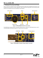
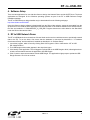
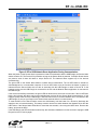
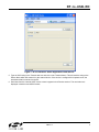
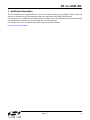
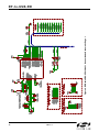
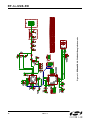
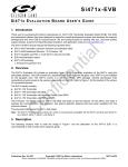
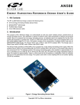
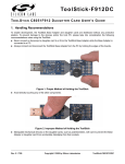
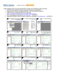
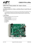
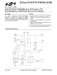
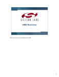
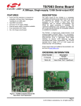
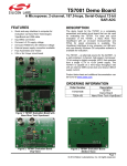
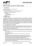
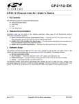
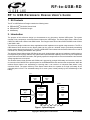
RF-to-USB-RD RF TO USB R EFERENCE D ESIGN U SER ’ S G UIDE 1. Kit Contents The RF to USB Reference Design contains the following items: EZRadioPRO® F912/4431 Sensor Node EZRadioPRO® F342/4431 Dongle AAA Battery 2. Introduction The purpose of this reference design is to demonstrate a very low-power, wireless USB system. The system consists of two components: a wireless Sensor Node and a USB Dongle. The Sensor Node uses a Silicon Labs C8051F912 MCU and a Silicon Labs Si4431 radio. The Dongle uses a Silicon Labs C8051F342 MCU and a Silicon Labs Si4431 radio. The reference design includes two demo applications which implement some typical usage scenarios. The RF to USB Network Demo shows how the Sensor Node can be used as a wireless sensor, periodically transmitting remote sensor data back to the host PC. The RF to USB UART Demo shows how the Sensor Node can be used as a wireless link, shuttling data between two systems. The wireless Sensor Node and the USB Dongle are small, simple designs and easy to implement, enabling them to be inexpensively and quickly added to any system that requires wireless capability. There are very few components required other than the MCU and radio, and typically expensive components such as a wired antenna and external voltage regulator are not required. The wireless Sensor Node operates at 915 MHz and is powered by a single AAA battery and uses the on-chip dcdc converter of the C8051F912 to provide power for the EZRadioPRO® radio and the other components. When the wireless Sensor Node is not transmitting or receiving data, it can remain in a low-power state where it only consumes 50 nA. The power efficiency of the Sensor Node allows it to operate on a single cell battery for an extended period of time. The estimated battery life is seven years, limited primarily by the self-discharge of the battery. PC Network Demo GUI UART Demo GUI Dongle Network Dongle App UART Dongle App USB Node HID Bootloader Network Node App App Firmware Image UART Node App EZRadioPRO EZRadioPRO Figure 1. System Diagram Rev. 0.1 12/09 Copyright © 2009 by Silicon Laboratories RF-to-USB-RD RF-to-USB-RD 3. Hardware Overview and Setup Figure 2 and Figure 3 identify the major components of the Sensor Node and the USB Dongle. Both devices come preloaded with the firmware for the demo applications. When using the demo applications, ensure that the printed antenna on the wireless board is not covered by the user’s fingers. UART Interface Button Potentiometer C8051F912 Printed Antenna Si4431 Figure 2. EZRadioPROF912/4431 Sensor Node The USB Dongle is powered by the PC through the USB connection. Connect the USB Dongle directly to the PC. The USB Dongle is HID based and requires no custom drivers to be installed. C8051F342 Si4431 Printed Antenna Figure 3. EZRadioPRO F342/4431 Dongle (plastic removed) 2 Rev. 0.1 RF-to-USB-RD 4. Software Setup There are two applications for use with this reference design: the Network Demo and the UART Demo. The demo applications are designed for the Windows operating systems as part of the RF to USB Reference Design installation package. The RF to USB Reference design Installer may be downloaded from the following web page: http://www.silabs.com/RFtoUSB Once the reference design software is downloaded from the Silicon Labs website, extract the executable from the zip file and run it to install the demo applications and documentation. If the software installed to the default location, the files are installed to C:\Silabs\MCU\RF_to_USB_RD\. Program shortcuts are also added to the Start Menu under the Silicon Laboratories folder. 5. RF to USB Network Demo The RF to USB Network demo shows how a Sensor Node can be used as a wireless sensor to periodically transmit data to the PC. To run the demo, first ensure that the hardware is connected as described in “3. Hardware Overview and Setup” and the software is installed as described in “4. Software Setup”. 1. Launch the program, which is found by clicking StartAll ProgramsSilicon LaboratoriesRF to USB RDNetwork Demo. 2. The USB Dongle serial number appears in the drop-down menu. 3. Click Identify in the application. This will trigger the yellow LED on the USB Dongle to blink, indicating that there is basic communication between the application and USB Dongle 4. Click Connect to start communication with the USB Dongle. The application might prompt to update the USB Dongle firmware. Click Yes to continue. Rev. 0.1 3 RF-to-USB-RD Figure 4. RF to USB Network Demo Application Initial Screen 5. Insert the AAA battery. If the battery has already been installed, please remove the AAA battery, press the button for at least one second to discharge the capacitor, release the button, then re-insert the battery. This will reset the MCU on the Sensor Node. Resetting the MCU will reset the Network application and put the Sensor Node in the correct starting state for the Network Demo. 6. On the Sensor Node, press the button. This will wake the MCU from sleep mode. The first time the button is pressed the Sensor Node will attempt to associate with the USB Dongle.The Sensor Node will blink green when transmitting and may blink red if association is unsuccessful. 7. After successful association, and upon each subsequent button press, the Sensor Node will transmit the potentiometer position and temperature data from the on-chip temperature sensor. It will wake up twice a second for 10 seconds to transmit data. After 10 seconds, the Sensor Node will go into ultra-low power sleep mode until the next button press. The Sensor Node will blink green each time it wakes up and transmits data.The Sensor Node may also blink red if the Sensor Node does not receive an acknowledgement from the USB Dongle. The USB Dongle will blink green each time it successfully receives a valid packet. 8. The PC application will designate the first Sensor Node to associate as Node 1. The temperature and potentiometer setting will displayed in the Node 1 section. Rotate the potentiometer on the Sensor Node while the green LED is blinking to see it dynamically update in the application. 4 Rev. 0.1 RF-to-USB-RD Figure 5. RF to USB Network Demo Application During Communication When the button on the Sensor Node is pressed to initiate communication with the USB Dongle, the Sensor Node obtains a Device ID. The Device ID is persistent as long as the Sensor Node is powered. If multiple Sensor Nodes are present, each of them will obtain a unique Device ID. The Network demo supports up to four devices simultaneously. The green LED on the Sensor Node blinks to indicate device transmission. The red LED blinks to indicate no acknowledgement or no association response. If the red LED blinks once the first time the button is pushed, it indicates that the Sensor Node was not able to associate with the USB Dongle to obtain a Device ID. If this happens, make sure the USB Dongle is connected to the PC and the Network Demo application is connected to the USB Dongle. If the device successfully associated, the green LED will blink twice a second for ten seconds. If the red LED also blinks, this indicates that there was no acknowledgement received for the Sensor Node’s transmissions. If this happens, please make sure the USB Dongle is still connected to the PC and the Network GUI is connected to the USB Dongle. Do not put your finger on the Sensor Node antenna while it is communicating. To reset the MCU on the Sensor Node, remove the AAA battery, hold the button for a second to discharge the capacitor, then re-insert the battery. The battery must be removed to switch between the Network Demo and the UART demo. If the Sensor Node LEDs blink for more than ten seconds, it is running the UART demo. Remove the battery, and reset the MCU. If the USB Dongle red LED illuminates continuously, this indicates a hardware error has occurred. Unplug the USB Dongle from the PC and try again. Rev. 0.1 5 RF-to-USB-RD 6. RF to USB UART Demo The RF to USB UART Demo shows how a Sensor Node can be used as a wireless link to transmit data between two systems. The Sensor Node has four test points for the UART interface, as shown in Figure 6. In order to perform this demo, an external UART device must be connected to the UART interface. The UART interface operates at 19,200 baud, 8 data bits, no parity, one stop bit (8-N-1), and no handshaking. The logic level of the UART is 2.1 V, which is available on the VDD pin. Use the VDD pin to set the voltage level for the external UART device. If an external UART interface is not available, the device can be configured for loopback mode by connecting the TX and RX pins together. In this configuration, any data sent from the PC application will be transmitted to the Sensor Node and transmitted back to the PC application. The CP2103EK UART-to-USB bridge Evaluation Kit, available separately, may be used in conjunction with the Sensor Node to provide UART-to-USB virtual COM port connectivity. The CP2103EK is recommended because it provides a separate VIO connection, which should be connected to the VDD pin of the Sensor Node UART connector. GND TX RX VDD UART Figure 6. Sensor Node UART Interface The following steps describe how to perform the UART demo: 1. Connect the external UART device to the RX, TX, and GND pins of the UART interface, or connect the TX and RX pins together for loopback mode. 2. Remove the battery from Sensor Node. Press and hold the button on the Sensor Node, and reinsert the battery. Release the button on the Sensor Node. The LEDs will blink quickly for 10 seconds or until the button is released. This step configures the Sensor Node to run the UART demo instead of the Network demo. 3. Launch the UART demo, which is found by clicking StartAll Programs Silicon LaboratoriesRF to USB RDUART Demo. 4. The USB Dongle serial number appears in the drop-down menu. Click Connect to start communication with the USB Dongle. The application might prompt to update the USB Dongle firmware. Click Yes to continue. 6 Rev. 0.1 RF-to-USB-RD Figure 7. RF to USB UART Demo Application Initial Screen 5. Type an ASCII string in the Transmit text box and click on the Transmit button. This will send the string to the Sensor Node which will transmit it to the external device. If the device is configured for loopback mode, the transmitted data is sent back to the PC. 6. Send data from the external UART device to have it appear in the Receive text box. The received text is displayed in both hex and ASCII formats. Rev. 0.1 7 RF-to-USB-RD Figure 8. RF to USB UART Demo Application During Communication When the Sensor Node receives any UART data on the RX pin, it will wake from the low power mode and transmit data immediately. The Sensor Node also polls the USB Dongle once per second. If there is any data waiting, the Sensor Node will retrieve pending data. The LED indications are similar to the Network Demo. The Sensor Node green LED will blinks when it transmits data. The USB Dongle green LED will blink when it receives data. The Sensor Node red LED will blink if it does not receive an acknowledgement from the USB Dongle. If the USB Dongle red LED illuminates continuously this indicates are hardware fault. Note: The UART demo is a point-to-point RF demo. The UART demo does not support more than one Sensor Node. If the UART communication is not working as expected, test the RF link using the loop-back mode first. Most problems occur due to incorrect baud rate settings. Use an oscilloscope to check the bit time in both directions. The UART demo Sensor Node will stop polling after 8 hours of inactivity. This will conserve battery power if the UART is not used. Press the button to wake up the UART demo after 8 hours. Remove the battery from the Sensor Node to stop the UART demo. 8 Rev. 0.1 RF-to-USB-RD 7. Additional Information The RF to USB RD uses a 915 MHz RF link. The demo firmware is written on top of EZMAC® PRO. The RF link data rate is 100 kbps using GFSK modulation. Both demo applications use EZMAC PRO channel 0. The output power is +13 dB for both the USB Dongle and Sensor Node. The PCB antennas on both Sensor Node and USB Dongle are designed for lowest possible cost, not maximum range. For firmware source code or additional information, please contact MCU support. http://www.silabs.com/support/ Rev. 0.1 9 Figure 9. EZRadioPRO® F912/4431 Sensor Node Schematic Page 1 RF-to-USB-RD 10 Rev. 0.1 Figure 10. EZRadioPRO® F912/4431 Sensor Node Schematic Page 2 RF-to-USB-RD Rev. 0.1 11 Figure 11. EZRadioPRO® F342/4431 Dongle Schematic RF-to-USB-RD 12 Rev. 0.1 RF-to-USB-RD NOTES: Rev. 0.1 13 RF-to-USB-RD CONTACT INFORMATION Silicon Laboratories Inc. 400 West Cesar Chavez Austin, TX 78701 Tel: 1+(512) 416-8500 Fax: 1+(512) 416-9669 Toll Free: 1+(877) 444-3032 Please visit the Silicon Labs Technical Support web page: https://www.silabs.com/support/pages/contacttechnicalsupport.aspx and register to submit a technical support request. The information in this document is believed to be accurate in all respects at the time of publication but is subject to change without notice. Silicon Laboratories assumes no responsibility for errors and omissions, and disclaims responsibility for any consequences resulting from the use of information included herein. Additionally, Silicon Laboratories assumes no responsibility for the functioning of undescribed features or parameters. Silicon Laboratories reserves the right to make changes without further notice. Silicon Laboratories makes no warranty, representation or guarantee regarding the suitability of its products for any particular purpose, nor does Silicon Laboratories assume any liability arising out of the application or use of any product or circuit, and specifically disclaims any and all liability, including without limitation consequential or incidental damages. Silicon Laboratories products are not designed, intended, or authorized for use in applications intended to support or sustain life, or for any other application in which the failure of the Silicon Laboratories product could create a situation where personal injury or death may occur. Should Buyer purchase or use Silicon Laboratories products for any such unintended or unauthorized application, Buyer shall indemnify and hold Silicon Laboratories harmless against all claims and damages. Silicon Laboratories and Silicon Labs are trademarks of Silicon Laboratories Inc. Other products or brandnames mentioned herein are trademarks or registered trademarks of their respective holders 14 Rev. 0.1