1
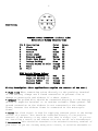
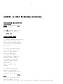
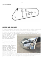
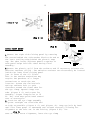
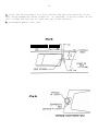
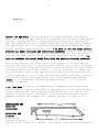
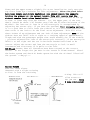
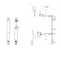
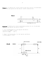
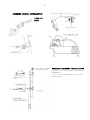
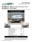
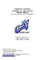
1
CHAMPION SIDECARS
DAYTONA 2+2 AND ESCORT
OWNERS MANUAL
GL 1500 with GL 1800 supplement
Champion Sidecars Inc.
11841 Monarch Street
Garden Grove, CA 92841
(800)875-0949 (sales)
(714)847-0949 (customer service)
(714)375-5668 (parts)
(714)847-1539 (fax)
http://www.champion sidecars.com (web site)
[email protected] (e-mail)
2
TABLE OF CONTENTS
PAGE
SPECIFICATIONS------------------------------Information on tire size, wheel bearings, brake pads
T.I.L.T. actuator and information regarding the
removal and re-installation of your sidecar.
GENERAL-------------------------------------Drawing of frame and suspension parts inc frame
and suspension parts list
ELECTRICAL----------------------------------Wiring harness pin location and color call out for
wiring harness installation to motorcycle.
Wiring of fuse link, ground, clock and accessories.
brake lights, running lights, right turn signal,
and back up light.
wiring of canopy switch (Daytona Sidecar)
T.I.L.T. electrical installation.
INSTALLATION OF LOWER FRONT MOUNT-----------Continued installation of lower front mount
including templet and instructions for cutting
plastic
INSTALLATION OF UPPER FRONT MOUNT-----------Continued installation of upper front mount
including diagrams for fairing modification.
INSTALLATION OF REAR SUB FRAME--------------Continued installation of rear sub frame
BRAKES--------------------------------------PREPARATION AND MOUNTING OF SIDECAR TO
MOTORCYCLE----------------------------------This section covers all aspects of installing the
sidecar to the motorcycle including helpful hints for
pre installation.
Mounting of sidecar continued. This section includes
instructions on wheel lead, toe in, and torque specs.
Mounting of sidecar continued. Diagrams showing
hardware used in the installation of the Daytona
and Escort sidecar.
Mounting of sidecar continued to include diagram
showing the correct frame height and location of
measurement points for the Daytona and Escort
sidecar installation.
STEERING DAMPER ------------------------------Drawings showing installation of steering damper
for the GL-1500.
Drawing showing reinstallation of Markland Backrest
DRIVING A SIDECAR------------------------------
3
4
5
6
7
8
9
10
11
12
13
13
14
15
16
17
18
3
Helpful hints and safety precautions for the first
time sidecar rider and sidecar passenger.
Also information regarding what to expect when you take
your sidecar for it’s first ride.
SPECIFICATIONS
TIRE
WHEEL
WHEEL BEARINGS
WHEEL BEARING SEAL
BRAKE PADS
SHOCK Progressive
T.I.L.T. ACTUATOR
-----------------------------------------------------------------------
145SR13 DUNLOP
#22-3511 4 x 100 modified to 4 x 4
#L44643 bearings L44610 race
#AD7128EO
#220018 Brembo
Escort#6602-007 Daytona#6602-011
20A at 1500 lbs.
CARE AND MAINTENANCE
PAINT Champion uses only PPG paint products for maximum quality and finish.
Your sidecar is painted using only base coat/clear coat urethane finishes.
This finish is hand polished at the factory and requires very little
maintenance except normal wash and wax. It is advisable not to wax your
sidecar for roughly three to four weeks after receiving it in order for the
paint to cure thoroughly.
WHEEL BEARING MAINTENANCE The wheel bearings used on your sidecar are
automotive grade tapered wheel bearings. It is advisable to check the wheel
bearing adjustment periodically, and to clean and re-pack the bearings
roughly every 3000 miles. These bearings and seals are available at most
automotive part stores.
TIRE AND TIRE AIR PRESSURE The tire used on your Daytona or Escort sidecar
is manufactured by the Dunlop Tire Co. and is available at most tire
centers. This tire is manufactured to automotive stress and ware factors
that are much higher then those you will ever experience with your sidecar.
There is a good chance that through normal use of your sidecar you will
never wear out the tire tread, but you must inspect the tire periodically
for air pressure, dry rot and sidewall damage. The manufacturer recommended
air pressure for this tire is 28 lbs. psi but because of the light duty
application this tire is being used for you may want to experiment with the
tire pressure to enhance the suspension comfort.
SHOCK SUSPENSION The shock suspension used on the Daytona and the Escort
sidecar are manufactured by Progressive Suspension. Progressive Suspension
has a reputation for manufacturing high quality aftermarket motorcycle
shocks and springs. Although the sidecar is shipped to you from the factory
with the shock spring set at it’s softest setting, there are a total of
five performance adjustments you can set your shock spring at.
SIDECAR REMOVAL AND REINSTALLATION To remove the sidecar from the
motorcycle first remove the two ½" bolts connecting the struts to their
upper eye mounting positions. Be sure to have someone support the
motorcycle as you remove the last of the ½" bolts . Now with the side stand
in it’s down position lean the motorcycle to the left so it rests on the
side stand. Now with the sidecar frame supported with a jack or dolly
remove the two lower 5/8" bolts connecting the lower mounting positions.
4
Disconnect the wiring harness plug, brake quick coupler, and steering
damper if you are using one. Now slide the sidecar away from the
motorcycle. (IMPORTANT NOTE)( UNLESS IT IS YOUR INTENT TO RE-ALIGN THE
SIDECAR DO NOT LOOSEN ANY OF THE JAM NUTS OR PINCH BOLTS DURING REMOVAL OF
THE SIDECAR) To reinstall the sidecar reverse the process.
5
6
ELECTRICAL
SIDECAR POWER CONNECTOR (sidecar side)
Motorcycle Wiring Diagram Code
Pin # Description
1
Clock
2
Accessory
3
Ground
4
Brake Light
5
Running Light
6
Right Turn Signal
7
Backup Utility
8
Canopy Switch on Bike
9
TILT
10
TILT
Color
Green
Red
Black
Red
White
Yellow
Blue
Orange
Yellow
Pink
Gauge
22
18
18
22
22
22
22
22
14
14
TILT Switch Wiring Colors
Positive Battery (+)
Negative Battery (-)
Harness Yellow
14
Harness Pink
14
Red
Black
Yellow
Purple
14
14
14
14
Wiring Description (Most applications require the removal of the seat.)
* Fuse link When connecting wires directly to the positive terminal
of the battery always use a fused connection to prevent fire or
damage to motorcycle and sidecar if a short occurs.
* Ground The ground wire should be connected directly to the battery
ground or negative terminal or to another suitable frame ground. The
ground connection on the sidecar is not connected to the sidecar
frame, however the sidecar frame is connected to the motorcycle
frame.
* Clock The clock signal is used for supplying constant power to the backup
circuit of a stereo. This should be connected directly to the positive
terminal of the battery or any other wire that is always live . IF you are
not installing a stereo in the sidecar this wire can be left disconnected.
* Accessories This should be attached to the switched accessory terminal of
your bike. If you are already using this circuit, it would be advisable to
7
use the accessory terminal to control a relay that feeds this. This will
prevent overloading the accessory circuit on your bike.
* Brake Lights
Running Lights
Right Turn Signal
Backup
These wires need to attach to the corresponding signal from the motorcycle.
There are several ways to do this. The first method is to remove the seat
and locate the corresponding wires with the use of a test light. The second
method although more expensive is to install a Station 9 from Kriss
Industries, where most of the wires to the sidecar can be isolated and
fused. On motorcycles that have a reverse gear such as the GL1500 you can
locate the reverse wire using a test light and by engaging the reverse gear
lever.(This wire on most GL1500 motorcycles is white with a blue stripe.)
If you do not have a reverse gear on your motorcycle the sidecar backup
light makes a very useful utility light when wired to a positive battery
connection and to a switch.
We suggest that you remove the right turn signal bulbs from your motorcycle
and cover the appropriate terminals with a small piece of electrical tape;
then replace the bulbs. This will prevent any confusion by following
motorists that could result from having two signals flashing, especially at
night when the extra signal appears to be in the center of the vehicle. If
you remove the sidecar, remember to put the bulbs back to their original
condition.
* Canopy Switch on Bike (Daytona Sidecar) This goes to a momentary switch
installed anywhere on the bike to open the canopy latch. It is recommended
that the power to this switch comes from switched power on the bike , thus
only allowing the canopy to be opened when the bike is switched on.
* TILT There are a total of 6 wires involved in the TILT system. The red
and black wires of the second harness need to go to the positive and
negative terminal of the battery respectively.. This is because of the high
current draw. The switch is momentary only and therefore cannot cause
unnecessary drain on the battery. You must run the power for this through a
20 amp fuse. The yellow and purple wires from the switch are connected
directly to the yellow and pink wires from the harness using the butt
connectors provided.
Mount the switch in a convenient location on the left side of your fairing.
The switch should be mounted so that moving it to the left or away from the
sidecar causes the sidecar to lift and the motorcycle to lean to the left.
Moving the switch to the right or toward the sidecar should cause the
sidecar to lower and cause motorcycle to lean to the right.
8
GOLDWING
GL-1500/6 RH Mounting Instructions
PREPARATION AND MOUNTING
PROCEDURES
NOTE; Reference to LH
(left hand)
and RH (right hand) is
with rider on bike.
(Fig -A)
LOWER FRONT MOUNT
1. Remove three 5mm screws
from the front of the
lower front faring panel
and carefully drop down
the cover.
2. Pull out the top of
the rubber boot at the
rear of the engine
crash guard bolt,
located in front of
brake pedal. Insert a
socket wrench above
the rubber boot and
loosen engine crash
guard bolt
approximately two
turns.
3. Remove the front
engine crash guard
bolt (figure A #1) and
DISCARD! This bolt
(Fig
A-1)
will be replaced later
with an 8mm x 1.25 x
100 bolt, flat washer and lock washer INCLUDED IN THE MOUNTING KIT
9
4. Remove the 10mm frame bolt (Figure A #2) next to this hole for
installation later. Position the arm assembly so the side plate is between
the frame and the engine crash guard as shown.(Figure A #1)
10
(CUT OUT TEMPLET)
CONTINUED LOWER FRONT MOUNT
5. Install the 8mm x 100 mm bolt, flat washer and lock washer as shown and
hand tighten . Re-install the 10 mm frame bolt in the original hole.
6. Locate the tube clamp on the bike cross member (Figure A-1 #1) and
secure the end of the arm assembly using the nylock nuts and torque to 10
ft. Lbs. Torque the frame
bolt to 20 ft. lbs. and
8mm bolt to 10 ft. lbs.
Re-torque the rear guard
bolt through the boot.
7. Position the templet
supplied (Figure C) on the
lower front fairing panel
as shown and using
reference point (Figure C1 #1) and line up the
templet to the existing
hole in the panel. Now cut
out the lower mount
clearance hole to the same
shape as the templet. You
may want to mark position
2 and 3 of (Figure C-1) and cut out with a hole saw. This will assist you
with the cutting of the clearance hole. For ease of assembly replace this
panel at the same time as the panel for the upper front mount.
11
12
( Fig D -1)
(Fig D -2)
(Fig E)
UPPER FRONT MOUNT
1.Remove the right side fairing panel by removing
the screws behind the side marker black trim and at
the lower trailing edge behind the plastic snap
cap. The tabs locate adjacent panels together so
each panel helps hold the other during final
assembly.
2.Remove the plastic grill from the radiator and if necessary relocate the
emission canister (fig E). The emission canister can alternately be located
inside the lower front fairing panel
just in front of the oil filter.
This is the easiest method but may
require the purchase of a longer
vacuum hose to reach the new
location. Loosen the fan box bolt
and top radiator bolt to gain
clearance around the frame tube for
the eye clamp. Spread clamp over
tube (Figure D -1) and rotate for
assembly. Torque clamp bolts to 10
ft. lbs. with nuts positioned toward
rear of motorcycle.
3. Position the eye clamp assembly
to point straight out from bike and
as high as possible (Figure D -1) and (Figure -F). Snug eye bolt by hand
until the lower panel is remounted and located correctly allowing for
alignment to the hole cut in the fairing (Figure F #1). For
(Fig F)
ease of front strut alignment, leave the eye clamp
13
hand tight at this time, but will be torqued to 55ft.lbs. during the front
strut installation.
14
4. Place the fairing panel on a flat surface and mark the position of the
hole using dimensions shown (Figure G). If required, trim the corner of the
grill inside the fairing to clear the top of the canister.
5. Reassemble panels with care.
(Fig G)
(Fig H)
15
(Fig I)
REAR MOUNT TO MOTORCYCLE
Remove the seat. There are
no
provisions for re-mounting
the right
(Fig J)
side seat grab handle with
a sidecar installation due
to limited space. Drill out
the threaded insert in the
front right handle mounting boss, of the motorcycle frame to accept a ½"
bolt, (Figure I). CAUTION: Do not damage the wiring when the drill passes
through the motorcycle frame.
Insert the ½" bolt through the large flanged spacer supplied and install
into the motorcycle frame. Install the captive nut and tighten as shown.
Figure J #1 #2 #4 #5
Drill the captive nut plate and frame using a 13/64th drill as shown on
(Figure J-#1) * Note The hole should be drilled off center to clear the
1\2" bolt. Using a pop rivet tool install the pop rivet to the captive nut
plate and into the frame. Remove the bolt and check to see that the bolt
will easily restart into the captive nut. Drill the right seat grab handle
holes in the seat base to accept the flanged 3/4" spacer provided Figure J2. The 3/4"spacer goes to the front seat hole. Be careful not to damage the
seat vinyl while drilling the holes.(Note) The wiring harness should be
installed onto the motorcycle while the seat is off.
16
Remove the right side
panel/battery cover if you have
not already done so. Also at this
time remove the right passenger
floor board and filler panel as
shown to allow access to the
saddle bag guard bolt. Remove the
saddlebag
guard bolt. Drill the saddle bag
guard bolt hole oversize to 3/8"
for clearance.
(Fig K)
With wiring complete to the
motorcycle and the plug
positioned so it can not be
pulled apart easily when it is installed. (Recheck wiring before installing
the seat) Replace the seat onto the motorcycle using the stock bolts and
grab handle on the left side. Do not tighten securely until the opposite
side is installed and aligned. Ensure the two flanged spacers in the seat
holes you have drilled out on the right side of the seat are still
inserted. You are now ready to install the rear mount onto the motorcycle.
*Caution: Protect the saddlebag so as not to scratch it during installation
of the mount. Align and start the ½" bolt (Figure K #1) and the 3/8" bolt
(Figure K #3) through the mount. Ensure that the seat spacer is aligned.
Do not tighten until both bolts are started.
On the Gl-1500 it will be necessary to trim the floor board cover as shown
to allow access to the right saddlebag guard bolt and clearance of the
mount.(figure K-1).
(NOTE) For clearance of the rear mount assembly it may be necessary to
grind the right rear adjustable floor board.
Tighten sub-frame mounting bolts at this time.
17
(Fig k-1)
BRAKES (IF EQUIPPED) With the exception of Harley Davidson the sidecar
brakes on most bike applications are integrated into the front brake master
cylinder. This connection is accomplished by removing the existing banjo
bolt and replacing it with a longer double banjo bolt supplied by Champion.
The double banjo bolt will go through both the new brake cable banjo end
and the existing brake cable banjo end. ( be sure to use new crush washers
between all banjo fittings and connecting surfaces).On the GL1500 the brake
line should run from the front master cylinder under the gas tank plastic
and with the female quick coupler ending up under the battery cover. (Be
sure to insulate the metal brake line from the positive battery terminal)
This can be done by placing a piece of hose around the brake cable in the
area of the battery. The brake cable to the sidecar is aircraft quality
steel braided hose with a quick disconnect coupler. This coupler is sealed
in both directions to prevent any brake fluid from leaking out. The sidecar
is shipped without any brake fluid so it will be necessary to replace the
fluid with DOT 4 brake fluid and bleed the brake system before riding the
sidecar combination. Also at any time the front brake lever feels spongy or
softer than normal, the sidecar brake line should be bled and checked.
(NOTE) It is recommended to bleed the brakes every 3rd. or 4th time the
sidecar is removed.
* Gl 1500 Note we strongly recommend that a Champion large volume front
brake master cylinder be installed to compensate for fluid volume feeding
to the sidecar brake. This item may be purchased after you receive your
sidecar by sending your front master cylinder including brake lever to
Champion Sidecars and Champion will upgrade the unit you send to us.
PREPARATION AND
MOUNTING
PROCEDURES
ATTACHING THE
SIDECAR
Mounting the
sidecar should be
done on a level even floor surface.
The sidecar frame should be supported
18
at the front and rear cross member on 4x4 blocks or stands adjusted to a
length of six and a half inches for the rear and seven and a half inches in
the front for the Daytona and Escort (Figure L). If you have T.I.L.T.
installed on the sidecar, retract the wheel to ensure the wheel does not
support the weight of the sidecar. Slide the front and rear mounting
hardware into the sidecar frame. To ease adjustments, excess powder coat
may have to be trimmed off the leading edge of the tubes before being
inserted into the frame tubes. For the Escort installation the front uses
the 45 degree boss and 45 degree clamp while the rear uses the 70 degree
boss and curved 70 degree clamp. The Daytona installation uses a 45 degree
clamp and 45 degree boss in the front and a 90 degree boss in the rear. The
use of the 90 degree boss on the Daytona sidecar is one of our newest
upgrades. When installing the 90 degree
boss into the rear position of the sidecar frame it is necessary to locate
the collar on the 90 degree boss and slide it all the way into the frame
until the collar hits the frame tube. By sliding the 90 degree up to the
collar it will preset the rear toe in measurement (Figure M location A) to
factory specifications.
The motorcycle ride height should be adjusted to simulate your current
riding height. This can usually be accomplished by removing all the air
from your rear shocks to a close approximation of bike height with a rider
on it.
Wheel the motorcycle alongside the sidecar in preparation for an average 60
inch MC wheel to SC wheel measurement. Use two jack stands to balance the
motorcycle. One should be placed under each rear bag guard and adjusted to
just balance the motorcycle not support it as full weight should be on the
suspension. A false setting of the frame or MC suspension will require you
to readjust the alignment settings just when you think everything is
completed.
The wheel lead should be set as per the diagram (Figure M location C). The
toe in measurement should be made using a long straight edge supported off
the ground about 4" and resting against the sidecar tire. The straight edge
should be 5' to 6' long. If you do not have a long straight edge, a 6'
flourescent bulb will work fine.
Engage the lower rear mount insert then snug up the 5/8" through bolt. Do
the same for the front lower mount. For the Gl-1500 adjust the lower mounts
as appropriate to obtain 1 1/4" of toe in with regular steering. If an Easy
steer front end has been installed, then use three quarters of an inch of
toe in. All the half inch fasteners should be final torque to 80 ft lbs. at
this time.
After you have torqued the half inch pinch bolts to 85 ft. lbs., you should
now install the rear strut and front strut from the sidecar frame eye to
the upper rear mount eye. It may be necessary to rotate the eyes on the
19
frame and the upper mounts slightly for strut installation (only turn the
top front frame eye clockwise for this adjustment). After the pinch bolts
have been torque and struts installed, you should remove the supports
holding the sidecar at its correct height. This will assure that the
sidecar remains level after installation. The motorcycle should be set up
so that it leans away from the sidecar. (ie, the upper part of the rear
wheel) should be about 1/4" further away from the SC than the bottom of the
MC wheel. The lean out or lean in of the motorcycle is accomplished by
adjusting the struts only. If you have the optional TILT (trimming device)
it is a good idea to first lower the sidecar to it’s full down position and
then raise it one inch to do the final strut adjustment. This will allow
three inches of up adjustment and one inch of down adjustment. NOTE If the
sidecar does not drift left or right at a cruising speed of approximately
50 mph and with the passenger weight that would normally be in the sidecar
, you have adjusted the lean of the motorcycle correctly. If the motorcycle
drift’s to the right and the toe in has been checked and found to be
correct adjust the struts and lean the motorcycle to left in small
increments and vice-versa if it pulls to the left.
RE-Check Ensure that all fasteners have been torqued to the correct
values. Do not forget the jam nuts in the struts or frame mounts! Bleed
the brake system and check SC brake operation with the SC wheel lifted off
the ground. ---Enjoy!---
Chrome Struts
Push the outer sleeve
downward with a slight twisting
to free it from the retaining
O Ring. This will
allow access to
the jam nut. (keep
O ring lubricated)
20
21
Figure L, is showing the correct frame height and location of measurement
points for the Daytona and the Escort sidecar installation.
(Fig L)
Figure M is showing the correct measurement points for toe in and wheel
lead for the Daytona and Escort sidecar.
1. Toe in measurement for the Daytona and Escort.
(without E-Z STEER 1-1/4")
(with E-Z STEER
3/4" )
2. Wheel lead measurement for the Daytona and Escort
( GL1500 approx. 6.50")
(Fig M)
22
STEERING DAMPER INSTALLATION
(1988 TO
1998)
MARKLAND BACKREST INSTALLATION
(There are no provisions from
Champion
for the re-mounting of other
backrests)
23
DRIVING A SIDECAR
NEW OWNER DRIVING AND SAFETY PRECAUTIONS
It is important to know that driving a sidecar will be nothing like riding
a solo motorcycle. So take my advice and forget most of the twenty years of
experience you have spent riding motorcycles and be prepared to spend some
time to change habits and learn some new tricks.
First of all forget leaning the motorcycle into a turn (it will not happen)
so remember if you do not turn the handlebars into a turn the motorcycle
will go straight. This may sound funny but many times old habits are very
strong and hard to break.
Remember also that there is a sidecar attached to the right hand side of
you motorcycle and you must make a mental note to stay to the left side of
your lane. It is no longer necessary and is unsafe to lower your feet from
the foot pegs when the vehicle is moving, except when you want to push the
rig in reverse.
It is very possible that on a fast or tight right hand turn the sidecar
wheel will lift off the ground. For the first time rider it is a good idea
to avoid this maneuver until you become more familiar with your sidecar.
The lifting of the sidecar wheel can be avoided in a number of ways. The
first and most common method is simply slow down on right hand turns until
you become familiar with your sidecar. The second method is to make sure
that there is always a passenger or additional weight in the sidecar and to
avoid having a passenger on the back of the bike when the sidecar is empty.
(but still watch your speed on right turns). After you become more familiar
with your sidecar you may want to take the rig into an empty parking lot
with no obstructions for the following maneuver. Put the sidecar rig into a
right hand turn and slowly increase the speed and the tightness of the turn
until the sidecar wheel comes off the ground. This maneuver will allow you
to safely experience what it feels like to have the wheel off the ground
and will avoid the unknown if it happens by accident while driving the rig.
Because it will put unnecessary stress on the sidecar mounting hardware the
raising of the sidecar should only be for learning purpose.
It is normal to feel the rig want to pull slightly to the right when
accelerating because of the pull of the sidecar and a slight pull to the
left when backing off the throttle. This is a normal reaction of attaching
a sidecar to a motorcycle and after you have some riding experience with
your sidecar you will hardly notice it. Some motorcycle sidecar
applications will experience what we call low speed (wheel-wobble)and it
usually occurs between first and second gear at about twenty or thirty MPH.
If you are experiencing intolerant wheel-wobble and you are sure the toe in
measurement and wheel lead settings are correct you may want to install a
steering damper (available from Champion) to the front fork of your
motorcycle.
It is also normal if you do not have a brake on your sidecar to feel a
slight pull to the right when stopping you rig. This is because the sidecar
24
wants to come around the motorcycle when stopping. If you are stopping and
you do not have a brake you may want to counter steer into the sidecar in
order for the rig to stop straight. ( A brake at the sidecar wheel is a
safety benefit and should be installed especially when driving on wet or
slick roads.