1
Simulink®
Graphical User Interface
R2015a
How to Contact MathWorks
Latest news:
www.mathworks.com
Sales and services:
www.mathworks.com/sales_and_services
User community:
www.mathworks.com/matlabcentral
Technical support:
www.mathworks.com/support/contact_us
Phone:
508-647-7000
The MathWorks, Inc.
3 Apple Hill Drive
Natick, MA 01760-2098
Simulink® Graphical User Interface
© COPYRIGHT 1990–2015 by The MathWorks, Inc.
The software described in this document is furnished under a license agreement. The software may be used
or copied only under the terms of the license agreement. No part of this manual may be photocopied or
reproduced in any form without prior written consent from The MathWorks, Inc.
FEDERAL ACQUISITION: This provision applies to all acquisitions of the Program and Documentation
by, for, or through the federal government of the United States. By accepting delivery of the Program
or Documentation, the government hereby agrees that this software or documentation qualifies as
commercial computer software or commercial computer software documentation as such terms are used
or defined in FAR 12.212, DFARS Part 227.72, and DFARS 252.227-7014. Accordingly, the terms and
conditions of this Agreement and only those rights specified in this Agreement, shall pertain to and
govern the use, modification, reproduction, release, performance, display, and disclosure of the Program
and Documentation by the federal government (or other entity acquiring for or through the federal
government) and shall supersede any conflicting contractual terms or conditions. If this License fails
to meet the government's needs or is inconsistent in any respect with federal procurement law, the
government agrees to return the Program and Documentation, unused, to The MathWorks, Inc.
Trademarks
MATLAB and Simulink are registered trademarks of The MathWorks, Inc. See
www.mathworks.com/trademarks for a list of additional trademarks. Other product or brand
names may be trademarks or registered trademarks of their respective holders.
Patents
MathWorks products are protected by one or more U.S. patents. Please see
www.mathworks.com/patents for more information.
Revision History
September 2007
March 2008
October 2008
March 2009
September 2009
March 2010
September 2010
April 2011
September 2011
March 2012
September 2012
March 2013
September 2013
March 2014
October 2014
March 2015
Online only
Online only
Online only
Online only
Online only
Online only
Online only
Online only
Online only
Online only
Online only
Online only
Online only
Online only
Online only
Online only
New for Simulink 7.0 (Release 2007b)
Revised for Simulink 7.1 (Release 2008a)
Revised for Simulink 7.2 (Release 2008b)
Revised for Simulink 7.3 (Release 2009a)
Revised for Simulink 7.4 (Release 2009b)
Revised for Simulink 7.5 (Release 2010a)
Revised for Simulink 7.6 (Release 2010b)
Revised for Simulink 7.7 (Release 2011a)
Revised for Simulink 7.8 (Release 2011b)
Revised for Simulink 7.9 (Release 2012a)
Revised for Simulink 8.0 (Release 2012b)
Revised for Simulink 8.1 (Release 2013a)
Revised for Simulink 8.2 (Release 2013b)
Revised for Simulink 8.3 (Release 2014a)
Revised for Simulink 8.4 (Release 2014b)
Revised for Simulink 8.5 (Release 2015a)
Contents
1
Configuration Parameters Dialog Box
Configuration Parameters Dialog Box Overview . . . . . . . . .
1-2
Model Configuration Pane . . . . . . . . . . . . . . . . . . . . . . . . . . . .
Model Configuration Overview . . . . . . . . . . . . . . . . . . . . . . .
Name . . . . . . . . . . . . . . . . . . . . . . . . . . . . . . . . . . . . . . . . . . .
Description . . . . . . . . . . . . . . . . . . . . . . . . . . . . . . . . . . . . . .
1-4
1-4
1-5
1-6
Solver Pane . . . . . . . . . . . . . . . . . . . . . . . . . . . . . . . . . . . . . . . . .
Solver Overview . . . . . . . . . . . . . . . . . . . . . . . . . . . . . . . . . .
Start time . . . . . . . . . . . . . . . . . . . . . . . . . . . . . . . . . . . . . .
Stop time . . . . . . . . . . . . . . . . . . . . . . . . . . . . . . . . . . . . . . .
Type . . . . . . . . . . . . . . . . . . . . . . . . . . . . . . . . . . . . . . . . . .
Solver . . . . . . . . . . . . . . . . . . . . . . . . . . . . . . . . . . . . . . . . .
Max step size . . . . . . . . . . . . . . . . . . . . . . . . . . . . . . . . . . .
Initial step size . . . . . . . . . . . . . . . . . . . . . . . . . . . . . . . . . .
Min step size . . . . . . . . . . . . . . . . . . . . . . . . . . . . . . . . . . . .
Relative tolerance . . . . . . . . . . . . . . . . . . . . . . . . . . . . . . . .
Absolute tolerance . . . . . . . . . . . . . . . . . . . . . . . . . . . . . . . .
Shape preservation . . . . . . . . . . . . . . . . . . . . . . . . . . . . . . .
Maximum order . . . . . . . . . . . . . . . . . . . . . . . . . . . . . . . . . .
Solver reset method . . . . . . . . . . . . . . . . . . . . . . . . . . . . . .
Number of consecutive min steps . . . . . . . . . . . . . . . . . . . .
Solver Jacobian Method . . . . . . . . . . . . . . . . . . . . . . . . . . .
Tasking mode for periodic sample times . . . . . . . . . . . . . . .
Automatically handle rate transition for data transfer . . . .
Deterministic data transfer . . . . . . . . . . . . . . . . . . . . . . . . .
Higher priority value indicates higher task priority . . . . . . .
Zero-crossing control . . . . . . . . . . . . . . . . . . . . . . . . . . . . . .
Time tolerance . . . . . . . . . . . . . . . . . . . . . . . . . . . . . . . . . .
Number of consecutive zero crossings . . . . . . . . . . . . . . . . .
Algorithm . . . . . . . . . . . . . . . . . . . . . . . . . . . . . . . . . . . . . .
Signal threshold . . . . . . . . . . . . . . . . . . . . . . . . . . . . . . . . .
1-7
1-9
1-11
1-12
1-14
1-17
1-24
1-26
1-28
1-30
1-32
1-34
1-36
1-38
1-40
1-42
1-44
1-46
1-48
1-50
1-52
1-54
1-56
1-58
1-60
v
vi
Contents
Periodic sample time constraint . . . . . . . . . . . . . . . . . . . . .
Fixed-step size (fundamental sample time) . . . . . . . . . . . . .
Sample time properties . . . . . . . . . . . . . . . . . . . . . . . . . . . .
Extrapolation order . . . . . . . . . . . . . . . . . . . . . . . . . . . . . . .
Number Newton's iterations . . . . . . . . . . . . . . . . . . . . . . . .
Allow tasks to execute concurrently on target . . . . . . . . . . .
1-62
1-65
1-67
1-70
1-72
1-73
Data Import/Export Pane . . . . . . . . . . . . . . . . . . . . . . . . . . . .
Data Import/Export Overview . . . . . . . . . . . . . . . . . . . . . . .
Input . . . . . . . . . . . . . . . . . . . . . . . . . . . . . . . . . . . . . . . . . .
Initial state . . . . . . . . . . . . . . . . . . . . . . . . . . . . . . . . . . . . .
Time . . . . . . . . . . . . . . . . . . . . . . . . . . . . . . . . . . . . . . . . . .
States . . . . . . . . . . . . . . . . . . . . . . . . . . . . . . . . . . . . . . . . .
Output . . . . . . . . . . . . . . . . . . . . . . . . . . . . . . . . . . . . . . . . .
Final states . . . . . . . . . . . . . . . . . . . . . . . . . . . . . . . . . . . . .
Format . . . . . . . . . . . . . . . . . . . . . . . . . . . . . . . . . . . . . . . .
Limit data points to last . . . . . . . . . . . . . . . . . . . . . . . . . . .
Decimation . . . . . . . . . . . . . . . . . . . . . . . . . . . . . . . . . . . . .
Save complete SimState in final state . . . . . . . . . . . . . . . . .
Signal logging . . . . . . . . . . . . . . . . . . . . . . . . . . . . . . . . . . .
Signal logging format . . . . . . . . . . . . . . . . . . . . . . . . . . . .
Data stores . . . . . . . . . . . . . . . . . . . . . . . . . . . . . . . . . . . .
Output options . . . . . . . . . . . . . . . . . . . . . . . . . . . . . . . . .
Refine factor . . . . . . . . . . . . . . . . . . . . . . . . . . . . . . . . . . .
Output times . . . . . . . . . . . . . . . . . . . . . . . . . . . . . . . . . . .
Save simulation output as single object . . . . . . . . . . . . . . .
Record logged workspace data in Simulation Data Inspector
Enable live streaming of selected signals to Simulation Data
Inspector . . . . . . . . . . . . . . . . . . . . . . . . . . . . . . . . . . . .
1-75
1-77
1-78
1-80
1-82
1-84
1-86
1-88
1-90
1-92
1-94
1-96
1-98
1-101
1-104
1-106
1-108
1-110
1-111
1-113
Optimization Pane: General . . . . . . . . . . . . . . . . . . . . . . . . .
Optimization Pane: General Tab Overview . . . . . . . . . . . .
Block reduction . . . . . . . . . . . . . . . . . . . . . . . . . . . . . . . . .
Conditional input branch execution . . . . . . . . . . . . . . . . . .
Implement logic signals as Boolean data (vs. double) . . . . .
Application lifespan (days) . . . . . . . . . . . . . . . . . . . . . . . .
Use division for fixed-point net slope computation . . . . . . .
Use floating-point multiplication to handle net slope
corrections . . . . . . . . . . . . . . . . . . . . . . . . . . . . . . . . . . .
Default for underspecified data type . . . . . . . . . . . . . . . . .
Optimize using the specified minimum and maximum values
Remove root level I/O zero initialization . . . . . . . . . . . . . .
Use memset to initialize floats and doubles to 0.0 . . . . . . .
Remove internal data zero initialization . . . . . . . . . . . . . .
1-117
1-119
1-120
1-123
1-126
1-128
1-130
1-115
1-132
1-134
1-136
1-139
1-141
1-143
Optimize initialization code for model reference . . . . . . . .
Remove code from floating-point to integer conversions that
wraps out-of-range values . . . . . . . . . . . . . . . . . . . . . . .
Remove code from floating-point to integer conversions with
saturation that maps NaN to zero . . . . . . . . . . . . . . . . .
Remove code that protects against division arithmetic
exceptions . . . . . . . . . . . . . . . . . . . . . . . . . . . . . . . . . . .
Compiler optimization level . . . . . . . . . . . . . . . . . . . . . . . .
Verbose accelerator builds . . . . . . . . . . . . . . . . . . . . . . . . .
1-145
Optimization Pane: Signals and Parameters . . . . . . . . . . .
Optimization Pane: Signals and Parameters Tab Overview
Inline parameters . . . . . . . . . . . . . . . . . . . . . . . . . . . . . . .
Signal storage reuse . . . . . . . . . . . . . . . . . . . . . . . . . . . . .
Enable local block outputs . . . . . . . . . . . . . . . . . . . . . . . . .
Reuse local block outputs . . . . . . . . . . . . . . . . . . . . . . . . .
Eliminate superfluous local variables (Expression folding) .
Reuse global block outputs . . . . . . . . . . . . . . . . . . . . . . . .
Minimize data copies between local and global variables . .
Inline invariant signals . . . . . . . . . . . . . . . . . . . . . . . . . . .
Optimize global data access . . . . . . . . . . . . . . . . . . . . . . . .
Simplify array indexing . . . . . . . . . . . . . . . . . . . . . . . . . . .
Use memcpy for vector assignment . . . . . . . . . . . . . . . . . .
Memcpy threshold (bytes) . . . . . . . . . . . . . . . . . . . . . . . . .
Pack Boolean data into bitfields . . . . . . . . . . . . . . . . . . . .
Bitfield declarator type specifier . . . . . . . . . . . . . . . . . . . .
Loop unrolling threshold . . . . . . . . . . . . . . . . . . . . . . . . . .
Maximum stack size (bytes) . . . . . . . . . . . . . . . . . . . . . . .
Pass reusable subsystem outputs as . . . . . . . . . . . . . . . . .
Parameter structure . . . . . . . . . . . . . . . . . . . . . . . . . . . . .
Model Parameter Configuration Dialog Box . . . . . . . . . . .
1-156
1-158
1-158
1-161
1-163
1-165
1-167
1-170
1-171
1-173
1-175
1-177
1-179
1-181
1-182
1-184
1-186
1-187
1-189
1-191
1-193
Optimization Pane: Stateflow . . . . . . . . . . . . . . . . . . . . . . . .
Optimization Pane: Stateflow Tab Overview . . . . . . . . . . .
Use bitsets for storing state configuration . . . . . . . . . . . . .
Use bitsets for storing Boolean data . . . . . . . . . . . . . . . . .
Base storage type for automatically created enumerations .
1-195
1-196
1-197
1-199
1-201
Diagnostics Pane: Solver . . . . . . . . . . . . . . . . . . . . . . . . . . .
Solver Diagnostics Overview . . . . . . . . . . . . . . . . . . . . . . .
Algebraic loop . . . . . . . . . . . . . . . . . . . . . . . . . . . . . . . . . .
Minimize algebraic loop . . . . . . . . . . . . . . . . . . . . . . . . . . .
Block priority violation . . . . . . . . . . . . . . . . . . . . . . . . . . .
Min step size violation . . . . . . . . . . . . . . . . . . . . . . . . . . .
1-202
1-203
1-205
1-207
1-209
1-211
1-147
1-149
1-151
1-153
1-155
vii
Sample hit time adjusting . . . . . . . . . . . . . . . . . . . . . . . . .
Consecutive zero-crossings violation . . . . . . . . . . . . . . . . .
Unspecified inheritability of sample time . . . . . . . . . . . . .
Solver data inconsistency . . . . . . . . . . . . . . . . . . . . . . . . .
Automatic solver parameter selection . . . . . . . . . . . . . . . .
Extraneous discrete derivative signals . . . . . . . . . . . . . . .
State name clash . . . . . . . . . . . . . . . . . . . . . . . . . . . . . . . .
SimState interface checksum mismatch . . . . . . . . . . . . . .
SimState object from earlier release . . . . . . . . . . . . . . . . .
viii
Contents
1-213
1-215
1-217
1-219
1-221
1-223
1-225
1-226
1-228
Diagnostics Pane: Sample Time . . . . . . . . . . . . . . . . . . . . . .
Sample Time Diagnostics Overview . . . . . . . . . . . . . . . . . .
Source block specifies -1 sample time . . . . . . . . . . . . . . . .
Discrete used as continuous . . . . . . . . . . . . . . . . . . . . . . .
Multitask rate transition . . . . . . . . . . . . . . . . . . . . . . . . . .
Single task rate transition . . . . . . . . . . . . . . . . . . . . . . . .
Multitask conditionally executed subsystem . . . . . . . . . . .
Tasks with equal priority . . . . . . . . . . . . . . . . . . . . . . . . .
Enforce sample times specified by Signal Specification blocks
1-229
1-230
1-231
1-233
1-234
1-236
1-238
1-240
1-242
Diagnostics Pane: Data Validity . . . . . . . . . . . . . . . . . . . . .
Data Validity Diagnostics Overview . . . . . . . . . . . . . . . . .
Signal resolution . . . . . . . . . . . . . . . . . . . . . . . . . . . . . . . .
Division by singular matrix . . . . . . . . . . . . . . . . . . . . . . . .
Underspecified data types . . . . . . . . . . . . . . . . . . . . . . . . .
Simulation range checking . . . . . . . . . . . . . . . . . . . . . . . .
Wrap on overflow . . . . . . . . . . . . . . . . . . . . . . . . . . . . . . .
Saturate on overflow . . . . . . . . . . . . . . . . . . . . . . . . . . . . .
Inf or NaN block output . . . . . . . . . . . . . . . . . . . . . . . . . .
"rt" prefix for identifiers . . . . . . . . . . . . . . . . . . . . . . . . . .
Detect downcast . . . . . . . . . . . . . . . . . . . . . . . . . . . . . . . .
Detect overflow . . . . . . . . . . . . . . . . . . . . . . . . . . . . . . . . .
Detect underflow . . . . . . . . . . . . . . . . . . . . . . . . . . . . . . . .
Detect precision loss . . . . . . . . . . . . . . . . . . . . . . . . . . . . .
Detect loss of tunability . . . . . . . . . . . . . . . . . . . . . . . . . .
Detect read before write . . . . . . . . . . . . . . . . . . . . . . . . . .
Detect write after read . . . . . . . . . . . . . . . . . . . . . . . . . . .
Detect write after write . . . . . . . . . . . . . . . . . . . . . . . . . . .
Multitask data store . . . . . . . . . . . . . . . . . . . . . . . . . . . . .
Duplicate data store names . . . . . . . . . . . . . . . . . . . . . . . .
Detect multiple driving blocks executing at the same time
step . . . . . . . . . . . . . . . . . . . . . . . . . . . . . . . . . . . . . . . .
Underspecified initialization detection . . . . . . . . . . . . . . . .
Check undefined subsystem initial output . . . . . . . . . . . . .
1-244
1-246
1-247
1-249
1-251
1-252
1-254
1-256
1-258
1-260
1-262
1-264
1-266
1-268
1-270
1-272
1-274
1-276
1-278
1-280
1-282
1-284
1-286
Check preactivation output of execution context . . . . . . . .
Check runtime output of execution context . . . . . . . . . . . .
Array bounds exceeded . . . . . . . . . . . . . . . . . . . . . . . . . . .
Model Verification block enabling . . . . . . . . . . . . . . . . . . .
1-290
1-294
1-298
1-300
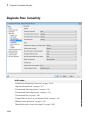
Diagnostics Pane: Type Conversion . . . . . . . . . . . . . . . . . .
Type Conversion Diagnostics Overview . . . . . . . . . . . . . . .
Unnecessary type conversions . . . . . . . . . . . . . . . . . . . . . .
Vector/matrix block input conversion . . . . . . . . . . . . . . . . .
32-bit integer to single precision float conversion . . . . . . . .
Detect underflow . . . . . . . . . . . . . . . . . . . . . . . . . . . . . . . .
Detect precision loss . . . . . . . . . . . . . . . . . . . . . . . . . . . . .
Detect overflow . . . . . . . . . . . . . . . . . . . . . . . . . . . . . . . . .
1-302
1-303
1-304
1-305
1-307
1-308
1-310
1-312
Diagnostics Pane: Connectivity . . . . . . . . . . . . . . . . . . . . . .
Connectivity Diagnostics Overview . . . . . . . . . . . . . . . . . .
Signal label mismatch . . . . . . . . . . . . . . . . . . . . . . . . . . . .
Unconnected block input ports . . . . . . . . . . . . . . . . . . . . .
Unconnected block output ports . . . . . . . . . . . . . . . . . . . .
Unconnected line . . . . . . . . . . . . . . . . . . . . . . . . . . . . . . . .
Unspecified bus object at root Outport block . . . . . . . . . . .
Element name mismatch . . . . . . . . . . . . . . . . . . . . . . . . . .
Mux blocks used to create bus signals . . . . . . . . . . . . . . . .
Bus signal treated as vector . . . . . . . . . . . . . . . . . . . . . . .
Non-bus signals treated as bus signals . . . . . . . . . . . . . . .
Repair bus selections . . . . . . . . . . . . . . . . . . . . . . . . . . . . .
Invalid function-call connection . . . . . . . . . . . . . . . . . . . . .
Context-dependent inputs . . . . . . . . . . . . . . . . . . . . . . . . .
1-314
1-316
1-317
1-318
1-319
1-320
1-321
1-323
1-325
1-328
1-331
1-333
1-335
1-337
Diagnostics Pane: Compatibility . . . . . . . . . . . . . . . . . . . . .
Compatibility Diagnostics Overview . . . . . . . . . . . . . . . . .
S-function upgrades needed . . . . . . . . . . . . . . . . . . . . . . . .
Block behavior depends on frame status of signal . . . . . . .
1-339
1-340
1-341
1-342
Diagnostics Pane: Model Referencing . . . . . . . . . . . . . . . . .
Model Referencing Diagnostics Overview . . . . . . . . . . . . .
Model block version mismatch . . . . . . . . . . . . . . . . . . . . . .
Port and parameter mismatch . . . . . . . . . . . . . . . . . . . . . .
Invalid root Inport/Outport block connection . . . . . . . . . . .
Unsupported data logging . . . . . . . . . . . . . . . . . . . . . . . . .
1-344
1-345
1-346
1-348
1-350
1-355
Diagnostics Pane: Saving . . . . . . . . . . . . . . . . . . . . . . . . . . .
Saving Tab Overview . . . . . . . . . . . . . . . . . . . . . . . . . . . .
1-357
1-358
ix
x
Contents
Block diagram contains disabled library links . . . . . . . . . .
Block diagram contains parameterized library links . . . . .
1-359
1-361
Diagnostics Pane: Stateflow . . . . . . . . . . . . . . . . . . . . . . . . .
Stateflow Diagnostics Overview . . . . . . . . . . . . . . . . . . . . .
Unused data and events . . . . . . . . . . . . . . . . . . . . . . . . . .
Unexpected backtracking . . . . . . . . . . . . . . . . . . . . . . . . . .
Invalid input data access in chart initialization . . . . . . . . .
No unconditional default transitions . . . . . . . . . . . . . . . . .
Transition outside natural parent . . . . . . . . . . . . . . . . . . .
Transition shadowing . . . . . . . . . . . . . . . . . . . . . . . . . . . .
Undirected event broadcasts . . . . . . . . . . . . . . . . . . . . . . .
Transition action specified before condition action . . . . . . .
Read-before-write to output in Moore chart . . . . . . . . . . . .
1-363
1-364
1-365
1-367
1-369
1-371
1-373
1-374
1-375
1-377
1-379
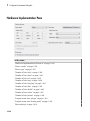
Hardware Implementation Pane . . . . . . . . . . . . . . . . . . . . .
Hardware Implementation Overview . . . . . . . . . . . . . . . . .
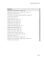
Device vendor . . . . . . . . . . . . . . . . . . . . . . . . . . . . . . . . . .
Device type . . . . . . . . . . . . . . . . . . . . . . . . . . . . . . . . . . . .
Number of bits: char . . . . . . . . . . . . . . . . . . . . . . . . . . . . .
Number of bits: short . . . . . . . . . . . . . . . . . . . . . . . . . . . .
Number of bits: int . . . . . . . . . . . . . . . . . . . . . . . . . . . . . .
Number of bits: long . . . . . . . . . . . . . . . . . . . . . . . . . . . . .
Number of bits: long long . . . . . . . . . . . . . . . . . . . . . . . . .
Number of bits: float . . . . . . . . . . . . . . . . . . . . . . . . . . . . .
Number of bits: double . . . . . . . . . . . . . . . . . . . . . . . . . . .
Number of bits: native . . . . . . . . . . . . . . . . . . . . . . . . . . .
Number of bits: pointer . . . . . . . . . . . . . . . . . . . . . . . . . . .
Largest atomic size: integer . . . . . . . . . . . . . . . . . . . . . . . .
Largest atomic size: floating-point . . . . . . . . . . . . . . . . . . .
Byte ordering . . . . . . . . . . . . . . . . . . . . . . . . . . . . . . . . . .
Signed integer division rounds to . . . . . . . . . . . . . . . . . . .
Shift right on a signed integer as arithmetic shift . . . . . . .
Enable long long . . . . . . . . . . . . . . . . . . . . . . . . . . . . . . . .
Test hardware is the same as production hardware . . . . . .
Device vendor . . . . . . . . . . . . . . . . . . . . . . . . . . . . . . . . . .
Device type . . . . . . . . . . . . . . . . . . . . . . . . . . . . . . . . . . . .
Number of bits: char . . . . . . . . . . . . . . . . . . . . . . . . . . . . .
Number of bits: short . . . . . . . . . . . . . . . . . . . . . . . . . . . .
Number of bits: int . . . . . . . . . . . . . . . . . . . . . . . . . . . . . .
Number of bits: long . . . . . . . . . . . . . . . . . . . . . . . . . . . . .
Number of bits: long long . . . . . . . . . . . . . . . . . . . . . . . . .
Number of bits: float . . . . . . . . . . . . . . . . . . . . . . . . . . . . .
Number of bits: double . . . . . . . . . . . . . . . . . . . . . . . . . . .
1-380
1-382
1-383
1-385
1-396
1-398
1-400
1-402
1-403
1-405
1-406
1-407
1-409
1-410
1-412
1-414
1-416
1-418
1-420
1-422
1-424
1-426
1-437
1-439
1-441
1-443
1-444
1-446
1-447
Number of bits: native . . . . . . . . . . . . . . . . . . . . . . . . . . .
Number of bits: pointer . . . . . . . . . . . . . . . . . . . . . . . . . . .
Largest atomic size: integer . . . . . . . . . . . . . . . . . . . . . . . .
Largest atomic size: floating-point . . . . . . . . . . . . . . . . . . .
Byte ordering . . . . . . . . . . . . . . . . . . . . . . . . . . . . . . . . . .
Signed integer division rounds to . . . . . . . . . . . . . . . . . . .
Shift right on a signed integer as arithmetic shift . . . . . . .
Enable long long . . . . . . . . . . . . . . . . . . . . . . . . . . . . . . . .
1-448
1-450
1-451
1-453
1-455
1-457
1-459
1-461
Model Referencing Pane . . . . . . . . . . . . . . . . . . . . . . . . . . . .
Model Referencing Pane Overview . . . . . . . . . . . . . . . . . .
Rebuild . . . . . . . . . . . . . . . . . . . . . . . . . . . . . . . . . . . . . . .
Never rebuild diagnostic . . . . . . . . . . . . . . . . . . . . . . . . . .
Enable parallel model reference builds . . . . . . . . . . . . . . .
MATLAB worker initialization for builds . . . . . . . . . . . . .
Total number of instances allowed per top model . . . . . . .
Pass fixed-size scalar root inputs by value for code
generation . . . . . . . . . . . . . . . . . . . . . . . . . . . . . . . . . . .
Minimize algebraic loop occurrences . . . . . . . . . . . . . . . . .
Propagate all signal labels out of the model . . . . . . . . . . . .
Propagate sizes of variable-size signals . . . . . . . . . . . . . . .
Model dependencies . . . . . . . . . . . . . . . . . . . . . . . . . . . . . .
1-463
1-465
1-466
1-475
1-477
1-479
1-481
Simulation Target Pane: General . . . . . . . . . . . . . . . . . . . .
Simulation Target: General Tab Overview . . . . . . . . . . . .
Detect wrap on overflow . . . . . . . . . . . . . . . . . . . . . . . . . .
Ensure responsiveness . . . . . . . . . . . . . . . . . . . . . . . . . . .
Echo expressions without semicolons . . . . . . . . . . . . . . . . .
Ensure memory integrity . . . . . . . . . . . . . . . . . . . . . . . . .
Generate typedefs for imported bus and enumeration types
Simulation target build mode . . . . . . . . . . . . . . . . . . . . . .
1-496
1-497
1-499
1-501
1-503
1-505
1-507
1-508
Simulation Target Pane: Symbols . . . . . . . . . . . . . . . . . . . .
Simulation Target: Symbols Tab Overview . . . . . . . . . . . .
Reserved names . . . . . . . . . . . . . . . . . . . . . . . . . . . . . . . .
1-510
1-511
1-512
Simulation Target Pane: Custom Code . . . . . . . . . . . . . . . .
Simulation Target: Custom Code Tab Overview . . . . . . . .
Parse custom code symbols . . . . . . . . . . . . . . . . . . . . . . . .
Source file . . . . . . . . . . . . . . . . . . . . . . . . . . . . . . . . . . . . .
Header file . . . . . . . . . . . . . . . . . . . . . . . . . . . . . . . . . . . .
Initialize function . . . . . . . . . . . . . . . . . . . . . . . . . . . . . . .
Terminate function . . . . . . . . . . . . . . . . . . . . . . . . . . . . . .
Include directories . . . . . . . . . . . . . . . . . . . . . . . . . . . . . . .
1-514
1-516
1-517
1-519
1-520
1-521
1-522
1-523
1-483
1-485
1-488
1-491
1-493
xi
Source files . . . . . . . . . . . . . . . . . . . . . . . . . . . . . . . . . . . .
Libraries . . . . . . . . . . . . . . . . . . . . . . . . . . . . . . . . . . . . . .
Use local custom code settings (do not inherit from main
model) . . . . . . . . . . . . . . . . . . . . . . . . . . . . . . . . . . . . . .
1-525
1-526
1-527
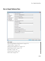
Run on Target Hardware Pane . . . . . . . . . . . . . . . . . . . . . .
1-529
Run on Target Hardware Pane Overview . . . . . . . . . . . . .
1-531
Target hardware . . . . . . . . . . . . . . . . . . . . . . . . . . . . . . . .
1-532
External mode transport layer . . . . . . . . . . . . . . . . . . . . .
1-533
Enable External mode . . . . . . . . . . . . . . . . . . . . . . . . . . . .
1-534
IP address . . . . . . . . . . . . . . . . . . . . . . . . . . . . . . . . . . . . .
1-535
Connection type . . . . . . . . . . . . . . . . . . . . . . . . . . . . . . . . .
1-536
Device name . . . . . . . . . . . . . . . . . . . . . . . . . . . . . . . . . . .
1-537
TCP/IP port (1024-65535) . . . . . . . . . . . . . . . . . . . . . . . . .
1-538
Enable overrun detection . . . . . . . . . . . . . . . . . . . . . . . . .
1-539
Device . . . . . . . . . . . . . . . . . . . . . . . . . . . . . . . . . . . . . . . .
1-540
Package name . . . . . . . . . . . . . . . . . . . . . . . . . . . . . . . . . .
1-541
Digital output to set on overrun . . . . . . . . . . . . . . . . . . . .
1-542
Enable communication between two NXT bricks . . . . . . . .
1-543
Bluetooth mode . . . . . . . . . . . . . . . . . . . . . . . . . . . . . . . . .
1-544
Slave Bluetooth address . . . . . . . . . . . . . . . . . . . . . . . . . .
1-545
Host name . . . . . . . . . . . . . . . . . . . . . . . . . . . . . . . . . . . . .
1-546
User name . . . . . . . . . . . . . . . . . . . . . . . . . . . . . . . . . . . . .
1-547
Password . . . . . . . . . . . . . . . . . . . . . . . . . . . . . . . . . . . . . .
1-548
Build directory . . . . . . . . . . . . . . . . . . . . . . . . . . . . . . . . .
1-549
Set host COM port . . . . . . . . . . . . . . . . . . . . . . . . . . . . . .
1-549
COM port number . . . . . . . . . . . . . . . . . . . . . . . . . . . . . . .
1-550
Analog input reference voltage . . . . . . . . . . . . . . . . . . . . .
1-550
Serial 0 baud rate, Serial 1 baud rate, Serial 2 baud rate, Serial
3 baud rate . . . . . . . . . . . . . . . . . . . . . . . . . . . . . . . . . .
1-551
IP address . . . . . . . . . . . . . . . . . . . . . . . . . . . . . . . . . . . . .
1-551
MAC address . . . . . . . . . . . . . . . . . . . . . . . . . . . . . . . . . . .
1-551
IP address . . . . . . . . . . . . . . . . . . . . . . . . . . . . . . . . . . . . .
1-552
Service set identifier (SSID) . . . . . . . . . . . . . . . . . . . . . . .
1-552
WiFi encryption . . . . . . . . . . . . . . . . . . . . . . . . . . . . . . . . .
1-552
WPA password . . . . . . . . . . . . . . . . . . . . . . . . . . . . . . . . .
1-552
WEP key . . . . . . . . . . . . . . . . . . . . . . . . . . . . . . . . . . . . . .
1-552
WEP key index . . . . . . . . . . . . . . . . . . . . . . . . . . . . . . . . .
1-552
xii
Contents
2
3
Library Browser
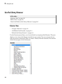
Use the Library Browser . . . . . . . . . . . . . . . . . . . . . . . . . . . . .
Libraries Pane . . . . . . . . . . . . . . . . . . . . . . . . . . . . . . . . . . . .
Blocks Pane . . . . . . . . . . . . . . . . . . . . . . . . . . . . . . . . . . . . . .
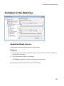
Search for Blocks in the Library Browser . . . . . . . . . . . . . . .
2-2
2-2
2-4
2-6
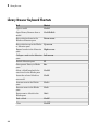
Library Browser Keyboard Shortcuts . . . . . . . . . . . . . . . . . . .
2-8
Signal Properties Dialog Box
Signal Properties Dialog Box Overview . . . . . . . . . . . . . . . . .
3-2
Signal Properties Controls . . . . . . . . . . . . . . . . . . . . . . . . . . . .
Signal name . . . . . . . . . . . . . . . . . . . . . . . . . . . . . . . . . . . . .
Signal name must resolve to Simulink signal object . . . . . . .
Show propagated signals . . . . . . . . . . . . . . . . . . . . . . . . . . . .
3-4
3-4
3-4
3-4
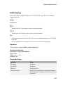
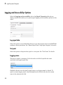
Logging and Accessibility Options . . . . . . . . . . . . . . . . . . . . .
Log signal data . . . . . . . . . . . . . . . . . . . . . . . . . . . . . . . . . . .
Test point . . . . . . . . . . . . . . . . . . . . . . . . . . . . . . . . . . . . . . .
Logging name . . . . . . . . . . . . . . . . . . . . . . . . . . . . . . . . . . . .
Data . . . . . . . . . . . . . . . . . . . . . . . . . . . . . . . . . . . . . . . . . . .
3-6
3-6
3-6
3-6
3-7
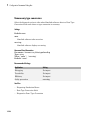
Simulink Coder Options . . . . . . . . . . . . . . . . . . . . . . . . . . . . . .
Package . . . . . . . . . . . . . . . . . . . . . . . . . . . . . . . . . . . . . . . . .
Storage class . . . . . . . . . . . . . . . . . . . . . . . . . . . . . . . . . . . . .
Storage type qualifier . . . . . . . . . . . . . . . . . . . . . . . . . . . . . .
3-8
3-8
3-8
3-8
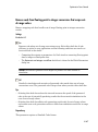
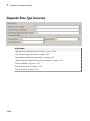
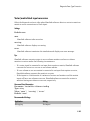
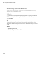
Data Transfer Options for Concurrent Execution . . . . . . . . .
Specify data transfer settings . . . . . . . . . . . . . . . . . . . . . . . .
Data transfer handling option . . . . . . . . . . . . . . . . . . . . . . . .
Extrapolation method (continuous-time signals) . . . . . . . . . .
Initial condition . . . . . . . . . . . . . . . . . . . . . . . . . . . . . . . . . . .
3-9
3-9
3-9
3-9
3-9
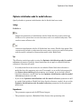
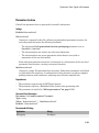
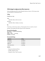
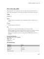
Documentation Options . . . . . . . . . . . . . . . . . . . . . . . . . . . . .
Description . . . . . . . . . . . . . . . . . . . . . . . . . . . . . . . . . . . . .
3-11
3-11
xiii
Document link . . . . . . . . . . . . . . . . . . . . . . . . . . . . . . . . . . .
4
Simulink Preferences Window
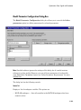
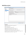
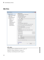
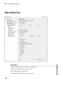
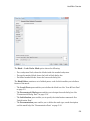
Main Pane . . . . . . . . . . . . . . . . . . . . . . . . . . . . . . . . . . . . . . . . . .
Simulink Preferences Window Overview . . . . . . . . . . . . . . . .
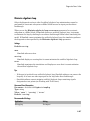
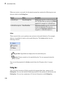
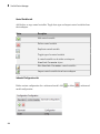
Model File Change Notification . . . . . . . . . . . . . . . . . . . . . . .
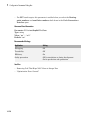
Updating or simulating the model . . . . . . . . . . . . . . . . . . . . .
Action . . . . . . . . . . . . . . . . . . . . . . . . . . . . . . . . . . . . . . . . . .
First editing the model . . . . . . . . . . . . . . . . . . . . . . . . . . . . .
Saving the model . . . . . . . . . . . . . . . . . . . . . . . . . . . . . . . .
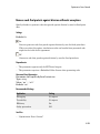
Autosave . . . . . . . . . . . . . . . . . . . . . . . . . . . . . . . . . . . . . . .
Save before updating or simulating the model . . . . . . . . . . .
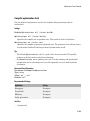
Save backup when overwriting a file created in an older version
of Simulink . . . . . . . . . . . . . . . . . . . . . . . . . . . . . . . . . . .
Warn when opening Model blocks with Normal Mode Visibility
set to off . . . . . . . . . . . . . . . . . . . . . . . . . . . . . . . . . . . . .
Notify when loading an old model . . . . . . . . . . . . . . . . . . . .
Do not load models created with a newer version of Simulink
Do not load models that are shadowed on the MATLAB path
Save a thumbnail image inside SLX files . . . . . . . . . . . . . .
Callback tracing . . . . . . . . . . . . . . . . . . . . . . . . . . . . . . . . .
Open the sample time legend whenever sample time display is
changed . . . . . . . . . . . . . . . . . . . . . . . . . . . . . . . . . . . . . .
File generation control . . . . . . . . . . . . . . . . . . . . . . . . . . . .
Simulation cache folder . . . . . . . . . . . . . . . . . . . . . . . . . . . .
Code generation folder . . . . . . . . . . . . . . . . . . . . . . . . . . . .
Print . . . . . . . . . . . . . . . . . . . . . . . . . . . . . . . . . . . . . . . . . .
Export . . . . . . . . . . . . . . . . . . . . . . . . . . . . . . . . . . . . . . . . .
Clipboard . . . . . . . . . . . . . . . . . . . . . . . . . . . . . . . . . . . . . . .
File format for new models and libraries . . . . . . . . . . . . . . .
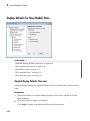
Display Defaults for New Models Pane . . . . . . . . . . . . . . . . .
Simulink Display Defaults Overview . . . . . . . . . . . . . . . . . .
Show masked subsystems . . . . . . . . . . . . . . . . . . . . . . . . . .
Show library links . . . . . . . . . . . . . . . . . . . . . . . . . . . . . . . .
Wide nonscalar lines . . . . . . . . . . . . . . . . . . . . . . . . . . . . . .
Show port data types . . . . . . . . . . . . . . . . . . . . . . . . . . . . .
xiv
Contents
3-11
4-2
4-3
4-6
4-7
4-8
4-9
4-10
4-11
4-12
4-13
4-15
4-16
4-17
4-18
4-19
4-20
4-21
4-22
4-23
4-24
4-24
4-25
4-26
4-26
4-28
4-28
4-30
4-31
4-33
4-34
5
Font Defaults for New Models Pane . . . . . . . . . . . . . . . . . . .
Simulink Font Defaults Overview . . . . . . . . . . . . . . . . . . . .
4-35
4-35
Editor Defaults Pane . . . . . . . . . . . . . . . . . . . . . . . . . . . . . . . .
Simulink Editor Defaults Overview . . . . . . . . . . . . . . . . . . .
Use classic diagram theme . . . . . . . . . . . . . . . . . . . . . . . . .
Line crossing style . . . . . . . . . . . . . . . . . . . . . . . . . . . . . . .
Scroll wheel controls zooming . . . . . . . . . . . . . . . . . . . . . . .
Enable smart editing features . . . . . . . . . . . . . . . . . . . . . . .
File Toolbar . . . . . . . . . . . . . . . . . . . . . . . . . . . . . . . . . . . . .
Print . . . . . . . . . . . . . . . . . . . . . . . . . . . . . . . . . . . . . . . . . .
Cut/Copy/Paste . . . . . . . . . . . . . . . . . . . . . . . . . . . . . . . . . .
Undo/Redo . . . . . . . . . . . . . . . . . . . . . . . . . . . . . . . . . . . . . .
Browse Back/Forward/Up . . . . . . . . . . . . . . . . . . . . . . . . . .
Library/Model Configuration/Model Explorer . . . . . . . . . . .
Refresh Blocks . . . . . . . . . . . . . . . . . . . . . . . . . . . . . . . . . . .
Update Diagram . . . . . . . . . . . . . . . . . . . . . . . . . . . . . . . . .
Simulation . . . . . . . . . . . . . . . . . . . . . . . . . . . . . . . . . . . . . .
Fast Restart . . . . . . . . . . . . . . . . . . . . . . . . . . . . . . . . . . . .
Debug Model . . . . . . . . . . . . . . . . . . . . . . . . . . . . . . . . . . . .
Model Advisor . . . . . . . . . . . . . . . . . . . . . . . . . . . . . . . . . . .
Build . . . . . . . . . . . . . . . . . . . . . . . . . . . . . . . . . . . . . . . . . .
Find . . . . . . . . . . . . . . . . . . . . . . . . . . . . . . . . . . . . . . . . . . .
4-36
4-37
4-37
4-38
4-38
4-38
4-38
4-39
4-39
4-39
4-39
4-39
4-39
4-39
4-39
4-39
4-40
4-40
4-40
4-40
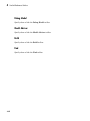
Data Management Defaults Pane . . . . . . . . . . . . . . . . . . . . .
Simulink Data Management Defaults Overview . . . . . . . . .
Package . . . . . . . . . . . . . . . . . . . . . . . . . . . . . . . . . . . . . . . .
4-41
4-41
4-41
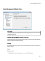
Configuration Defaults Pane . . . . . . . . . . . . . . . . . . . . . . . . .
Simulink Configuration Defaults Overview . . . . . . . . . . . . .
4-43
4-43
Simulink Mask Editor
Mask Editor Overview . . . . . . . . . . . . . . . . . . . . . . . . . . . . . . .
5-2
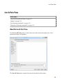
Icon & Ports Pane . . . . . . . . . . . . . . . . . . . . . . . . . . . . . . . . . . .
About the Icon & Ports Pane . . . . . . . . . . . . . . . . . . . . . . . .
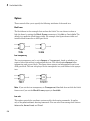
Options . . . . . . . . . . . . . . . . . . . . . . . . . . . . . . . . . . . . . . . . .
Icon drawing commands . . . . . . . . . . . . . . . . . . . . . . . . . . .
5-5
5-5
5-6
5-10
xv
6
xvi
Contents
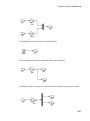
Examples of drawing commands . . . . . . . . . . . . . . . . . . . . .
5-11
Parameters & Dialog Pane . . . . . . . . . . . . . . . . . . . . . . . . . . .
About the Parameters & Dialog Pane . . . . . . . . . . . . . . . . .
Controls . . . . . . . . . . . . . . . . . . . . . . . . . . . . . . . . . . . . . . . .
Dialog box . . . . . . . . . . . . . . . . . . . . . . . . . . . . . . . . . . . . . .
Property editor . . . . . . . . . . . . . . . . . . . . . . . . . . . . . . . . . .
5-12
5-12
5-14
5-20
5-24
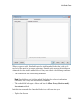
Initialization Pane . . . . . . . . . . . . . . . . . . . . . . . . . . . . . . . . . .
About the Initialization Pane . . . . . . . . . . . . . . . . . . . . . . .
Dialog variables . . . . . . . . . . . . . . . . . . . . . . . . . . . . . . . . .
Initialization commands . . . . . . . . . . . . . . . . . . . . . . . . . . .
Allow library block to modify its contents . . . . . . . . . . . . . .
Rules for Initialization commands . . . . . . . . . . . . . . . . . . . .
5-28
5-28
5-30
5-30
5-30
5-31
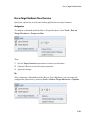
Documentation Pane . . . . . . . . . . . . . . . . . . . . . . . . . . . . . . . .
About the Documentation Pane . . . . . . . . . . . . . . . . . . . . . .
Mask type . . . . . . . . . . . . . . . . . . . . . . . . . . . . . . . . . . . . . .
Mask description . . . . . . . . . . . . . . . . . . . . . . . . . . . . . . . . .
Mask help . . . . . . . . . . . . . . . . . . . . . . . . . . . . . . . . . . . . . .
5-32
5-32
5-33
5-33
5-33
Concurrent Execution Window
Concurrent Execution Window: Main Pane . . . . . . . . . . . . . .
Concurrent Execution Window Overview . . . . . . . . . . . . . . .
Enable explicit model partitioning for concurrent behavior . .
6-2
6-2
6-5
Data Transfer Pane . . . . . . . . . . . . . . . . . . . . . . . . . . . . . . . . . .
Data Transfer Pane Overview . . . . . . . . . . . . . . . . . . . . . . . .
Periodic signals . . . . . . . . . . . . . . . . . . . . . . . . . . . . . . . . . . .
Continuous signals . . . . . . . . . . . . . . . . . . . . . . . . . . . . . . . .
Extrapolation method . . . . . . . . . . . . . . . . . . . . . . . . . . . . . .
Automatically handle rate transition for data transfer . . . . .
6-6
6-6
6-7
6-8
6-9
6-9
CPU Pane . . . . . . . . . . . . . . . . . . . . . . . . . . . . . . . . . . . . . . . . .
CPU Pane Overview . . . . . . . . . . . . . . . . . . . . . . . . . . . . . .
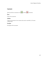
Name . . . . . . . . . . . . . . . . . . . . . . . . . . . . . . . . . . . . . . . . . .
6-11
6-11
6-12
Hardware Node Pane . . . . . . . . . . . . . . . . . . . . . . . . . . . . . . .
Hardware Node Pane Overview . . . . . . . . . . . . . . . . . . . . .
Name . . . . . . . . . . . . . . . . . . . . . . . . . . . . . . . . . . . . . . . . . .
Clock Frequency [MHz] . . . . . . . . . . . . . . . . . . . . . . . . . . . .
Color . . . . . . . . . . . . . . . . . . . . . . . . . . . . . . . . . . . . . . . . . .
6-13
6-13
6-14
6-14
6-14
Periodic Pane . . . . . . . . . . . . . . . . . . . . . . . . . . . . . . . . . . . . . .
Periodic Pane Overview . . . . . . . . . . . . . . . . . . . . . . . . . . . .
Name . . . . . . . . . . . . . . . . . . . . . . . . . . . . . . . . . . . . . . . . . .
Periodic Trigger . . . . . . . . . . . . . . . . . . . . . . . . . . . . . . . . . .
Color . . . . . . . . . . . . . . . . . . . . . . . . . . . . . . . . . . . . . . . . . .
Template . . . . . . . . . . . . . . . . . . . . . . . . . . . . . . . . . . . . . . .
6-16
6-16
6-17
6-18
6-19
6-19
Task Pane . . . . . . . . . . . . . . . . . . . . . . . . . . . . . . . . . . . . . . . . .
Task Pane Overview . . . . . . . . . . . . . . . . . . . . . . . . . . . . . .
Name . . . . . . . . . . . . . . . . . . . . . . . . . . . . . . . . . . . . . . . . . .
Period . . . . . . . . . . . . . . . . . . . . . . . . . . . . . . . . . . . . . . . . .
Color . . . . . . . . . . . . . . . . . . . . . . . . . . . . . . . . . . . . . . . . . .
6-20
6-20
6-21
6-22
6-23
Interrupt Pane . . . . . . . . . . . . . . . . . . . . . . . . . . . . . . . . . . . . .
Interrupt Pane Overview . . . . . . . . . . . . . . . . . . . . . . . . . . .
Name . . . . . . . . . . . . . . . . . . . . . . . . . . . . . . . . . . . . . . . . . .
Color . . . . . . . . . . . . . . . . . . . . . . . . . . . . . . . . . . . . . . . . . .
Aperiodic trigger source . . . . . . . . . . . . . . . . . . . . . . . . . . .
Signal number [2,SIGRTMAX-SIGRTMIN-1] . . . . . . . . . . .
Event name . . . . . . . . . . . . . . . . . . . . . . . . . . . . . . . . . . . . .
6-24
6-24
6-25
6-26
6-27
6-28
6-29
System Tasks Pane . . . . . . . . . . . . . . . . . . . . . . . . . . . . . . . . .
System Tasks Pane Overview . . . . . . . . . . . . . . . . . . . . . . .
6-30
6-30
System Task Pane . . . . . . . . . . . . . . . . . . . . . . . . . . . . . . . . . .
System Task Pane Overview . . . . . . . . . . . . . . . . . . . . . . . .
Name . . . . . . . . . . . . . . . . . . . . . . . . . . . . . . . . . . . . . . . . . .
Period . . . . . . . . . . . . . . . . . . . . . . . . . . . . . . . . . . . . . . . . .
Color . . . . . . . . . . . . . . . . . . . . . . . . . . . . . . . . . . . . . . . . . .
6-31
6-31
6-32
6-33
6-34
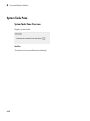
System Interrupt Pane . . . . . . . . . . . . . . . . . . . . . . . . . . . . . .
System Interrupt Pane Overview . . . . . . . . . . . . . . . . . . . .
Name . . . . . . . . . . . . . . . . . . . . . . . . . . . . . . . . . . . . . . . . . .
Color . . . . . . . . . . . . . . . . . . . . . . . . . . . . . . . . . . . . . . . . . .
6-35
6-35
6-36
6-37
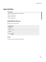
Profile Report Pane . . . . . . . . . . . . . . . . . . . . . . . . . . . . . . . . .
Profile Report Pane Overview . . . . . . . . . . . . . . . . . . . . . . .
6-38
6-38
xvii
Number of time steps . . . . . . . . . . . . . . . . . . . . . . . . . . . . .
7
Simulink Simulation Stepper
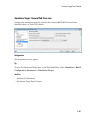
Simulation Stepping Options . . . . . . . . . . . . . . . . . . . . . . . . . .
Simulation Stepping Options Overview . . . . . . . . . . . . . . . . .
Enable stepping back . . . . . . . . . . . . . . . . . . . . . . . . . . . . . .
Maximum number of saved back steps . . . . . . . . . . . . . . . . .
Interval between stored back steps . . . . . . . . . . . . . . . . . . . .
Move back/forward by . . . . . . . . . . . . . . . . . . . . . . . . . . . . . .
Pause simulation when time reaches . . . . . . . . . . . . . . . . . .
8
xviii
Contents
6-39
7-2
7-2
7-4
7-5
7-6
7-7
7-8
Simulink Variant Manager
Variant Manager Overview . . . . . . . . . . . . . . . . . . . . . . . . . . .
8-2
Variant Configuration Data Pane . . . . . . . . . . . . . . . . . . . . . .
Name . . . . . . . . . . . . . . . . . . . . . . . . . . . . . . . . . . . . . . . . . . .
Configurations . . . . . . . . . . . . . . . . . . . . . . . . . . . . . . . . . . . .
Constraints . . . . . . . . . . . . . . . . . . . . . . . . . . . . . . . . . . . . . .
8-3
8-3
8-3
8-5
Model Hierarchy Pane . . . . . . . . . . . . . . . . . . . . . . . . . . . . . . .
Validate Configuration . . . . . . . . . . . . . . . . . . . . . . . . . . . . .
Show . . . . . . . . . . . . . . . . . . . . . . . . . . . . . . . . . . . . . . . . . . .
Hierarchy Table . . . . . . . . . . . . . . . . . . . . . . . . . . . . . . . . . .
8-6
8-6
8-7
8-7
Validation Results Pane . . . . . . . . . . . . . . . . . . . . . . . . . . . . . .
Source . . . . . . . . . . . . . . . . . . . . . . . . . . . . . . . . . . . . . . . . . .
Message . . . . . . . . . . . . . . . . . . . . . . . . . . . . . . . . . . . . . . . . .
8-9
8-9
8-9
1
Configuration Parameters Dialog Box
• “Configuration Parameters Dialog Box Overview” on page 1-2
• “Model Configuration Pane” on page 1-4
• “Solver Pane” on page 1-7
• “Data Import/Export Pane” on page 1-75
• “Optimization Pane: General” on page 1-117
• “Optimization Pane: Signals and Parameters” on page 1-156
• “Optimization Pane: Stateflow” on page 1-195
• “Diagnostics Pane: Solver” on page 1-202
• “Diagnostics Pane: Sample Time” on page 1-229
• “Diagnostics Pane: Data Validity” on page 1-244
• “Diagnostics Pane: Type Conversion” on page 1-302
• “Diagnostics Pane: Connectivity” on page 1-314
• “Diagnostics Pane: Compatibility” on page 1-339
• “Diagnostics Pane: Model Referencing” on page 1-344
• “Diagnostics Pane: Saving” on page 1-357
• “Diagnostics Pane: Stateflow” on page 1-363
• “Hardware Implementation Pane” on page 1-380
• “Model Referencing Pane” on page 1-463
• “Simulation Target Pane: General” on page 1-496
• “Simulation Target Pane: Symbols” on page 1-510
• “Simulation Target Pane: Custom Code” on page 1-514
• “Run on Target Hardware Pane” on page 1-529
1
Configuration Parameters Dialog Box
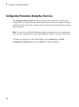
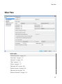
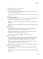
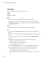
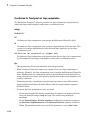
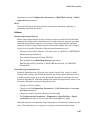
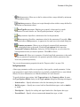
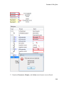
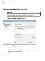
Configuration Parameters Dialog Box Overview
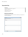
The Configuration Parameters dialog box specifies the settings for a model's active
configuration set. These parameters determine the type of solver used, import and export
settings, and other values that determine how the model runs. See Configuration Sets for
more information.
Note You can also use the Model Explorer to modify settings for the active configuration
set or any other configuration set. See “Model Explorer Overview” for more information.
To display the dialog box, in the Simulink Editor, select Simulation > Model
Configuration Parameters, or press Ctrl+E. The dialog box appears.
1-2
Configuration Parameters Dialog Box Overview
The dialog box groups the configuration parameters into various categories. To display
the parameters for a specific category, click the category in the Select tree on the left
side of the dialog box.
In most cases, Simulink software does not apply changes until you click OK or Apply
at the bottom of the dialog box. The OK button applies your changes and dismisses the
dialog box. The Apply button applies your changes but leaves the dialog box open.
Note Each of the parameters in the Configuration Parameters dialog box can also
be set via the sim command. Each parameter description includes the corresponding
command line information.
1-3
1
Configuration Parameters Dialog Box
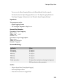
Model Configuration Pane
In this section...
“Model Configuration Overview” on page 1-4
“Name” on page 1-5
“Description” on page 1-6
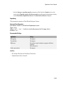
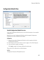
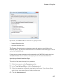
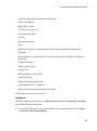
Model Configuration Overview
View or edit the name and description of your configuration set.
In the Model Explorer you can edit the name and description of your configuration sets.
In the Model Explorer or Simulink Preferences window you can edit the description
of your template configuration set, Model Configuration Preferences. Go to the Model
Configuration Preferences to edit the template Configuration Parameters to be used as
defaults for new models.
When editing the Model Configuration preferences, you can click Restore to Default
Preferences to restore the default configuration settings for creating new models. These
underlying defaults cannot be changed.
1-4
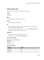
Model Configuration Pane
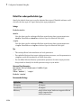
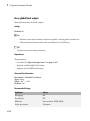
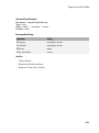
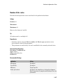
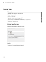
Name
Specify the name of your configuration set.
Settings
Default: Configuration (for Active configuration set) or Configuration
Preferences (for default configuration set).
Edit the name of your configuration set.
In the Model Configuration Preferences, the name of the default configuration is always
Configuration Preferences, and cannot be changed.
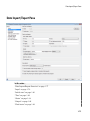
1-5
1
Configuration Parameters Dialog Box
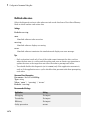
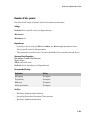
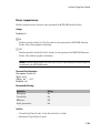
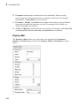
Description
Specify a description of your configuration set.
Settings
No Default
Enter text to describe your configuration set.
1-6
Solver Pane
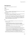
Solver Pane
In this section...
“Solver Overview” on page 1-9
“Start time” on page 1-11
“Stop time” on page 1-12
“Type” on page 1-14
“Solver” on page 1-17
“Max step size” on page 1-24
“Initial step size” on page 1-26
“Min step size” on page 1-28
“Relative tolerance” on page 1-30
1-7
1
Configuration Parameters Dialog Box
In this section...
“Absolute tolerance” on page 1-32
“Shape preservation” on page 1-34
“Maximum order” on page 1-36
“Solver reset method” on page 1-38
“Number of consecutive min steps” on page 1-40
“Solver Jacobian Method” on page 1-42
“Tasking mode for periodic sample times” on page 1-44
“Automatically handle rate transition for data transfer” on page 1-46
“Deterministic data transfer” on page 1-48
“Higher priority value indicates higher task priority” on page 1-50
“Zero-crossing control” on page 1-52
“Time tolerance” on page 1-54
“Number of consecutive zero crossings” on page 1-56
“Algorithm” on page 1-58
“Signal threshold” on page 1-60
“Periodic sample time constraint” on page 1-62
“Fixed-step size (fundamental sample time)” on page 1-65
“Sample time properties” on page 1-67
“Extrapolation order” on page 1-70
“Number Newton's iterations” on page 1-72
“Allow tasks to execute concurrently on target” on page 1-73
1-8
Solver Pane
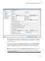
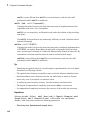
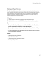
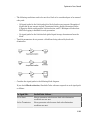
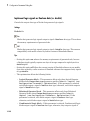
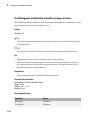
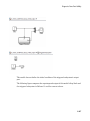
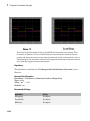
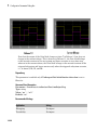
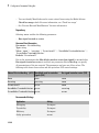
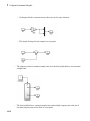
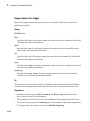
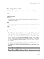
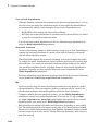
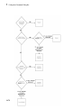
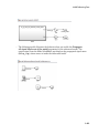
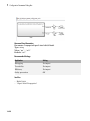
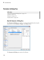
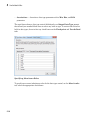
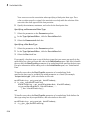
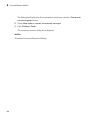
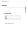
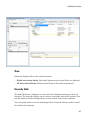
Solver Overview
Specify the simulation start and stop time, and the solver configuration for the
simulation. Use the Solver pane to set up a solver for a model's active configuration set.
A solver computes a dynamic system's states at successive time steps over a specified
time span, using information provided by the model. Once the model compiles, the Solver
Information tooltip displays
• Compiled solver name
• Step size (Max step size or Fixed step size)
Once the model compiles, the status bar displays the solver used for compiling and a
carat (^) when:
• Simulink selects a different solver during compilation.
• You set the step size to auto. The Solver Information tooltip displays the step size
that Simulink calculated.
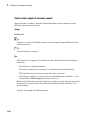
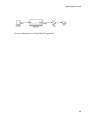
Configuration
1
2
3
4
Select a solver type from the Type list.
Select a solver from the Solver list.
Set the parameters displayed for the selected type and solver combination.
Apply the changes.
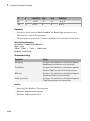
Tips
• To open the Solver pane, in the Simulink Editor, select Simulation > Model
Configuration Parameters > Solver.
• Simulation time is not the same as clock time. For example, running a simulation for
10 seconds usually does not take 10 seconds. Total simulation time depends on factors
such as model complexity, solver step sizes, and computer speed.
• Fixed-step solver type is required for code generation, unless you use an S-function
or RSim target.
• Variable-step solver type can significantly shorten the time required to simulate
models in which states change rapidly or which contain discontinuities.
See Also
• Choosing a Solver
1-9
1
Configuration Parameters Dialog Box
• Specifying a Simulation Start and Stop Time
• Solver Pane
1-10
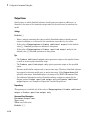
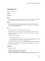
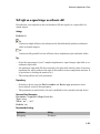
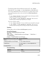
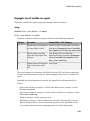
Solver Pane
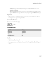
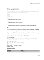
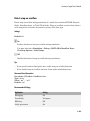
Start time
Specify the start time for the simulation or generated code as a double-precision value,
scaled to seconds.
Settings
Default: 0.0
• A start time must be less than or equal to the stop time. For example, use a nonzero
start time to delay the start of a simulation while running an initialization script.
• The values of block parameters with initial conditions must match the initial
condition settings at the specified start time.
• Simulation time is not the same as clock time. For example, running a simulation for
10 seconds usually does not take 10 seconds. Total simulation time depends on factors
such as model complexity, solver step sizes, and computer speed.
Command-Line Information
Parameter: StartTime
Type: string
Value: any valid value
Default: '0.0'
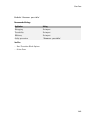
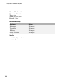
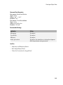
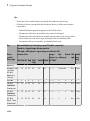
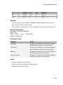
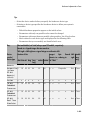
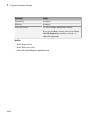
Recommended Settings
Application
Setting
Debugging
No impact
Traceability
No impact
Efficiency
No impact
Safety precaution
0.0
See Also
• Specifying a Simulation Start and Stop Time
• Solver Pane
1-11
1
Configuration Parameters Dialog Box
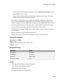
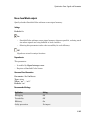
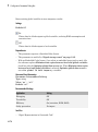
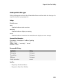
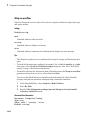
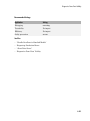
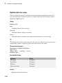
Stop time
Specify the stop time for the simulation or generated code as a double-precision value,
scaled to seconds.
Settings
Default: 10
• Stop time must be greater than or equal to the start time.
• Specify inf to run a simulation or generated program until you explicitly pause or
stop it.
• If the stop time is the same as the start time, the simulation or generated program
runs for one step.
• Simulation time is not the same as clock time. For example, running a simulation for
10 seconds usually does not take 10 seconds. Total simulation time depends on factors
such as model complexity, solver step sizes, and computer speed.
• If your model includes blocks that depend on absolute time and you are creating a
design that runs indefinitely, see “Blocks That Depend on Absolute Time”.
Command-Line Information
Parameter: StopTime
Type: string
Value: any valid value
Default: '10.0'
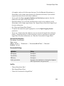
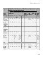
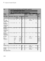
Recommended Settings
Application
Setting
Debugging
No impact
Traceability
No impact
Efficiency
No impact
Safety precaution
A positive value
See Also
• “Blocks That Depend on Absolute Time”
1-12
Solver Pane
• Using Blocks to Stop or Pause a Simulation
• Specifying a Simulation Start and Stop Time
• Solver Pane
1-13
1
Configuration Parameters Dialog Box
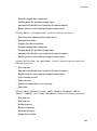
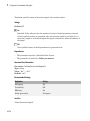
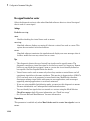
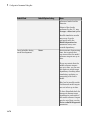
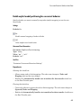
Type
Select the type of solver you want to use to simulate your model.
Settings
Default: Variable-step
Variable-step
Step size varies from step to step, depending on model dynamics. A variable-step
solver:
• Reduces step size when model states change rapidly, to maintain accuracy.
• Increases step size when model states change slowly, to avoid unnecessary steps.
Variable-step is recommended for models in which states change rapidly or that
contain discontinuities. In these cases, a variable-step solver requires fewer time
steps than a fixed-step solver to achieve a comparable level of accuracy. This can
significantly shorten simulation time.
Fixed-step
Step size remains constant throughout the simulation.
Required for code generation, unless you use an S-function or RSim target.
Note: The solver computes the next time as the sum of the current time and the step size.
Dependencies
Selecting Variable-step enables the following parameters:
• Solver
• Max step size
• Min step size
• Initial step size
• Relative tolerance
• Absolute tolerance
• Shape preservation
1-14
Solver Pane
• Initial step size
• Number of consecutive min steps
• Zero-crossing control
• Time tolerance
• Algorithm
Selecting Fixed-step enables the following parameters:
• Solver
• Periodic sample time constraint
• Fixed-step size (fundamental sample time)
• Tasking mode for periodic sample times
• Higher priority value indicates higher task priority
• Automatically handle rate transitions for data transfers
Command-Line Information
Parameter: SolverType
Type: string
Value: 'Variable-step' | 'Fixed-step'
Default: 'Variable-step'
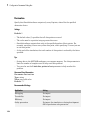
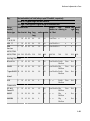
Recommended Settings
Application
Setting
Debugging
No impact
Traceability
No impact
Efficiency
No impact
Safety precaution
Fixed-step
See Also
• Solvers
• Choosing a Solver
• “Purely Discrete Systems”
• Solver Pane
1-15
1
Configuration Parameters Dialog Box
1-16
Solver Pane
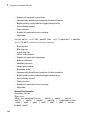
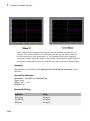
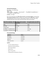
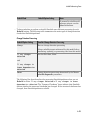
Solver
Select the solver you want to use to compute the model's states during simulation or code
generation.
Settings
The available solvers change depending on which solver Type you selected:
• “Fixed-step Solvers” on page 1-17
• “Variable-step Solvers” on page 1-18
Fixed-step Solvers
Default: ode3 (Bogacki-Shampine)
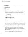
ode3 (Bogacki-Shampine)
Computes the model's state at the next time step as an explicit function of the
current value of the state and the state derivatives, using the Bogacki-Shampine
Formula integration technique to compute the state derivatives. In the following
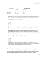
example, X is the state, DX is the state derivative, and h is the step size:
X(n+1) = X(n) + h * DX(n)
Discrete (no continuous states)
Computes the time of the next time step by adding a fixed step size to the current
time.
Use this solver for models with no states or discrete states only, using a fixed step
size. Relies on the model's blocks to update discrete states.
The accuracy and length of time of the resulting simulation depends on the size of
the steps taken by the simulation: the smaller the step size, the more accurate the
results but the longer the simulation takes.
Note: The fixed-step discrete solver cannot be used to simulate models that have
continuous states.
ode8 (Dormand-Prince RK8(7))
1-17
1
Configuration Parameters Dialog Box
Uses the eighth-order Dormand-Prince formula to compute the model state at the
next time step as an explicit function of the current value of the state and the state
derivatives approximated at intermediate points.
ode5 (Dormand-Prince)
Uses the fifth-order Dormand-Prince formula to compute the model state at the
next time step as an explicit function of the current value of the state and the state
derivatives approximated at intermediate points.
ode4 (Runge-Kutta)
Uses the fourth-order Runge-Kutta (RK4) formula to compute the model state at the
next time step as an explicit function of the current value of the state and the state
derivatives.
ode2 (Heun)
Uses the Heun integration method to compute the model state at the next time step
as an explicit function of the current value of the state and the state derivatives.
ode1 (Euler)
Uses the Euler integration method to compute the model state at the next time step
as an explicit function of the current value of the state and the state derivatives.
ode14x (extrapolation)
Uses a combination of Newton's method and extrapolation from the current value to
compute the model's state at the next time step, as an implicit function of the state
and the state derivative at the next time step. In the following example, X is the
state, DX is the state derivative, and h is the step size:
X(n+1) - X(n) - h * DX(n+1) = 0
This solver requires more computation per step than an explicit solver, but is more
accurate for a given step size.
Variable-step Solvers
Default: ode45 (Dormand-Prince)
ode45 (Dormand-Prince)
Computes the model's state at the next time step using an explicit Runge-Kutta (4,5)
formula (the Dormand-Prince pair) for numerical integration.
ode45 is a one-step solver, and therefore only needs the solution at the preceding
time point.
1-18
Solver Pane
Use ode45 as a first try for most problems.
Discrete (no continuous states)
Computes the time of the next step by adding a step size that varies depending on
the rate of change of the model's states.
Use this solver for models with no states or discrete states only, using a variable step
size.
ode23 (Bogacki-Shampine)
Computes the model's state at the next time step using an explicit Runge-Kutta (2,3)
formula (the Bogacki-Shampine pair) for numerical integration.
ode23 is a one-step solver, and therefore only needs the solution at the preceding
time point.
ode23 is more efficient than ode45 at crude tolerances and in the presence of mild
stiffness.
ode113 (Adams)
Computes the model's state at the next time step using a variable-order AdamsBashforth-Moulton PECE numerical integration technique.
ode113 is a multistep solver, and thus generally needs the solutions at several
preceding time points to compute the current solution.
ode113 can be more efficient than ode45 at stringent tolerances.
ode15s (stiff/NDF)
Computes the model's state at the next time step using variable-order numerical
differentiation formulas (NDFs). These are related to, but more efficient than the
backward differentiation formulas (BDFs), also known as Gear's method.
ode15s is a multistep solver, and thus generally needs the solutions at several
preceding time points to compute the current solution.
ode15s is efficient for stiff problems. Try this solver if ode45 fails or is inefficient.
ode23s (stiff/Mod. Rosenbrock)
Computes the model's state at the next time step using a modified Rosenbrock
formula of order 2.
ode23s is a one-step solver, and therefore only needs the solution at the preceding
time point.
1-19
1
Configuration Parameters Dialog Box
ode23s is more efficient than ode15s at crude tolerances, and can solve stiff
problems for which ode15s is ineffective.
ode23t (Mod. stiff/Trapezoidal)
Computes the model's state at the next time step using an implementation of the
trapezoidal rule with a “free” interpolant.
ode23t is a one-step solver, and therefore only needs the solution at the preceding
time point.
Use ode23t if the problem is only moderately stiff and you need a solution with no
numerical damping.
ode23tb (stiff/TR-BDF2)
Computes the model's state at the next time step using a multistep implementation
of TR-BDF2, an implicit Runge-Kutta formula with a trapezoidal rule first stage,
and a second stage consisting of a backward differentiation formula of order two. By
construction, the same iteration matrix is used in evaluating both stages.
ode23tb is more efficient than ode15s at crude tolerances, and can solve stiff
problems for which ode15s is ineffective.
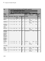
Tips
• Identifying the optimal solver for a model requires experimentation, for an in-depth
discussion, see Choosing a Solver.
• The optimal solver balances acceptable accuracy with the shortest simulation time.
• Simulink software uses a discrete solver for any model with no states or discrete
states only, even if you specify a continuous solver.
• A smaller step size increases accuracy, but also increases simulation time.
• The degree of computational complexity increases for oden, as n increases.
• As computational complexity increases, the accuracy of the results also increases.
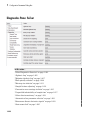
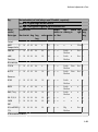
Dependencies
Selecting the ode1 (Euler) , ode2 (Huen), ode 3 (Bogacki-Shampine), ode4
(Runge-Kutta), ode 5 (Dormand-Prince), or Discrete (no continuous
states) fixed-step solvers enables the following parameters:
• Fixed-step size (fundamental sample time)
1-20
Solver Pane
• Periodic sample time constraint
• Tasking mode for periodic sample times
• Automatically handle rate transition for data transfers
• Higher priority value indicates higher task priority
Selecting ode14x (extrapolation) enables the following parameters:
• Fixed-step size (fundamental sample time)
• Extrapolation order
• Number Newton's iterations
• Periodic sample time constraint
• Tasking mode for periodic sample times
• Automatically handle rate transition for data transfers
• Higher priority value indicates higher task priority
Selecting the Discrete (no continuous states) variable-step solver enables the
following parameters:
• Max step size
• Automatically handle rate transition for data transfers
• Higher priority value indicates higher task priority
• Zero-crossing control
• Time tolerance
• Number of consecutive zero crossings
• Algorithm
Selecting ode45 (Dormand-Prince), ode23 (Bogacki-Shampine), ode113
(Adams), or ode23s (stiff/Mod. Rosenbrock) enables the following parameters:
• Max step size
• Min step size
• Initial step size
• Relative tolerance
• Absolute tolerance
• Shape preservation
1-21
1
Configuration Parameters Dialog Box
• Number of consecutive min steps
• Automatically handle rate transition for data transfers
• Higher priority value indicates higher task priority
• Zero-crossing control
• Time tolerance
• Number of consecutive zero crossings
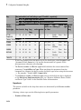
• Algorithm
Selecting ode15s (stiff/NDF), ode23t (Mod. stiff/Trapezoidal), or ode23tb
(stiff/TR-BDF2) enables the following parameters:
• Max step size
• Min step size
• Initial step size
• Solver reset method
• Number of consecutive min steps
• Relative tolerance
• Absolute tolerance
• Shape preservation
• Maximum order
• Automatically handle rate transition for data transfers
• Higher priority value indicates higher task priority
• Zero-crossing control
• Time tolerance
• Number of consecutive zero crossings
• Algorithm
Command-Line Information
Parameter: Solver
Type: string
Value: 'VariableStepDiscrete' | 'ode45' | 'ode23' | 'ode113' |
'ode15s' | 'ode23s' | 'ode23t' | 'ode23tb' | 'FixedStepDiscrete'
|'ode8'| 'ode5' | 'ode4' | 'ode3' | 'ode2' | 'ode1' | 'ode14x'
Default: 'ode45'
1-22
Solver Pane
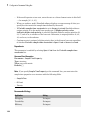
Recommended Settings
Application
Setting
Debugging
No impact
Traceability
No impact
Efficiency
No impact
Safety precaution
Discrete (no continuous states)
See Also
• Solvers
• Choosing a Solver
• “Purely Discrete Systems”
• Solver Pane
1-23
1
Configuration Parameters Dialog Box
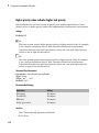
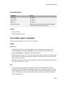
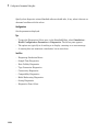
Max step size
Specify the largest time step that the solver can take.
Settings
Default: auto
• For the discrete solver, the default value (auto) is the model's shortest sample time.
• For continuous solvers, the default value (auto) is determined from the start and stop
times. If the stop time equals the start time or is inf, Simulink chooses 0.2 seconds
as the maximum step size. Otherwise, it sets the maximum step size to
hmax =
tstop - tstart
50
• For Sine and Signal Generator source blocks, Simulink calculates the max step size
using this heuristic:
hmax
Ê tsto p -tstart Ê 1 ˆ Ê 1 ˆ ˆ
, Á ˜ ÁÁ
˜
Ë 3 ¯ Ë Freqmax ˜¯ ˜¯
Ë 50
= min Á
where Freqmax is the maximum frequency (Hz) of these blocks in the model.
Tips
• Generally, the default maximum step size is sufficient. If you are concerned about the
solver missing significant behavior, change the parameter to prevent the solver from
taking too large a step.
• Max step size determines the step size of the variable-step solver.
• If the time span of the simulation is very long, the default step size might be too large
for the solver to find the solution.
• If your model contains periodic or nearly periodic behavior and you know the period,
set the maximum step size to some fraction (such as 1/4) of that period.
• In general, for more output points, change the refine factor, not the maximum step
size.
Dependencies
This parameter is enabled only if the solver Type is set to Variable-step.
1-24
Solver Pane
Command-Line Information
Parameter: MaxStep
Type: string
Value: any valid value
Default: 'auto'
Recommended Settings
Application
Setting
Debugging
No impact
Traceability
No impact
Efficiency
No impact
Safety precaution
No impact
See Also
• “Purely Discrete Systems”
• Solver Pane
1-25
1
Configuration Parameters Dialog Box
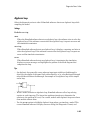
Initial step size
Specify the size of the first time step that the solver takes.
Settings
Default: auto
By default, the solver selects an initial step size by examining the derivatives of the
states at the start time.
Tips
• Be careful when increasing the initial step size. If the first step size is too large, the
solver might step over important behavior.
• The initial step size parameter is a suggested first step size. The solver tries this step
size but reduces it if error criteria are not satisfied.
Dependencies
This parameter is enabled only if the solver Type is set to Variable-step.
Command-Line Information
Parameter: InitialStep
Type: string
Value: any valid value
Default: 'auto'
Recommended Settings
Application
Setting
Debugging
No impact
Traceability
No impact
Efficiency
No impact
Safety precaution
No impact
See Also
• “Purely Discrete Systems”
• Improving Simulation Performance and Accuracy
1-26
Solver Pane
• Solver Pane
1-27
1
Configuration Parameters Dialog Box
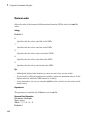
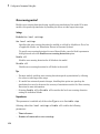
Min step size
Specify the smallest time step that the solver can take.
Settings
Default: auto
• The default value (auto) sets an unlimited number of warnings and a minimum step
size on the order of machine precision.
• You can specify either a real number greater than zero, or a two-element vector
for which the first element is the minimum step size and the second element is the
maximum number of minimum step size warnings before an error was issued.
Tips
• If the solver takes a smaller step to meet error tolerances, it issues a warning
indicating the current effective relative tolerance.
• Setting the second element to zero results in an error the first time the solver must
take a step smaller than the specified minimum. This is equivalent to changing the
Min step size violation diagnostic to error on the Diagnostics pane (see Min step
size violation).
• Setting the second element to -1 results in an unlimited number of warnings. This is
also the default if the input is a scalar.
• Min step size determines the step size of the variable step ODE solver. The size is
limited by the smallest discrete sample time in the model.
Dependencies
This parameter is enabled only if the solver Type is set to Variable-step.
Command-Line Information
Parameter: MinStep
Type: string
Value: any valid value
Default: 'auto'
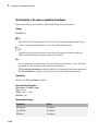
Recommended Settings
1-28
Application
Setting
Debugging
No impact
Solver Pane
Application
Setting
Traceability
No impact
Efficiency
No impact
Safety precaution
No impact
See Also
• “Purely Discrete Systems”
• Min step size violation
• Solver Pane
1-29
1
Configuration Parameters Dialog Box
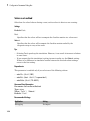
Relative tolerance
Specify the largest acceptable solver error, relative to the size of each state during each
time step. If the relative error exceeds this tolerance, the solver reduces the time step
size.
Settings
Default: 1e-3
• Setting the relative tolerance to auto is actually the default value of 1e-3.
• The relative tolerance is a percentage of the state's value.
• The default value (1e-3) means that the computed state is accurate to within 0.1%.
Tips
• The acceptable error at each time step is a function of both the Relative tolerance
and the Absolute tolerance. For more information about how these settings work
together, see Specifying Variable-Step Solver Error Tolerances.
• During each time step, the solver computes the state values at the end of the step and
also determines the local error – the estimated error of these state values. If the error
is greater than the acceptable error for any state, the solver reduces the step size and
tries again.
• The default relative tolerance value is sufficient for most applications. Decreasing the
relative tolerance value can slow down the simulation.
• To check the accuracy of a simulation after you run it, you can reduce the relative
tolerance to 1e-4 and run it again. If the results of the two simulations are not
significantly different, you can feel confident that the solution has converged.
Dependencies
This parameter is enabled only if you set:
• Solver Type to Variable-step.
• Solver to a continuous variable-step solver.
This parameter works along with Absolute tolerance to determine the acceptable error
at each time step. For more information about how these settings work together, see
Specifying Variable-Step Solver Error Tolerances.
1-30
Solver Pane
Command-Line Information
Parameter: RelTol
Type: string
Value: any valid value
Default: '1e-3'
Recommended Settings
Application
Setting
Debugging
No impact
Traceability
No impact
Efficiency
No impact
Safety precaution
No impact
See Also
• Specifying Variable-Step Solver Error Tolerances
• Improving Simulation Performance and Accuracy
• Solver Pane
1-31
1
Configuration Parameters Dialog Box
Absolute tolerance
Specify the largest acceptable solver error, as the value of the measured state approaches
zero. If the absolute error exceeds this tolerance, the solver reduces the time step size.
Settings
Default: auto
• The default value (auto) initially sets the absolute tolerance for each state to 1e-6.
As the simulation progresses, the absolute tolerance for each state is reset to the
maximum value that the state has thus far assumed times the relative tolerance for
that state.
For example, if a state goes from 0 to 1 and the Relative tolerance is 1e-3, then by
the end of the simulation, the Absolute tolerance is set to 1e-3.
• If the computed setting is not suitable, you can determine an appropriate setting
yourself.
Tips
• The acceptable error at each time step is a function of both the Relative tolerance
and the Absolute tolerance. For more information about how these settings work
together, see Specifying Variable-Step Solver Error Tolerances.
• The Integrator, Second-Order Integrator, Variable Transport Delay, Transfer Fcn,
State-Space, and Zero-Pole blocks allow you to specify absolute tolerance values
for solving the model states that they compute or that determine their output. The
absolute tolerance values that you specify in these blocks override the global setting
in the Configuration Parameters dialog box.
• You might want to override the Absolute tolerance setting using blocks if the
global setting does not provide sufficient error control for all of your model states, for
example, if they vary widely in magnitude.
• If you set the Absolute tolerance too low, the solver might take too many steps
around near-zero state values, and thus slow the simulation.
• To check the accuracy of a simulation after you run it, you can reduce the absolute
tolerance and run it again. If the results of the two simulations are not significantly
different, you can feel confident that the solution has converged.
• If your simulation results do not seem accurate, and your model has states whose
values approach zero, the Absolute tolerance may be too large. Reduce the
1-32
Solver Pane
Absolute tolerance to force the simulation to take more steps around areas of nearzero state values.
Dependencies
This parameter is enabled only if you set:
• Solver Type to Variable-step.
• Solver to a continuous variable-step solver.
This parameter works along with Relative tolerance to determine the acceptable error
at each time step. For more information about how these settings work together, see
Specifying Variable-Step Solver Error Tolerances.
Command-Line Information for Configuration Parameters
Parameter: AbsTol
Type: string | numeric value
Value: 'auto' | positive real scalar
Default: 'auto'
Recommended Settings
Application
Setting
Debugging
No impact
Traceability
No impact
Efficiency
No impact
Safety precaution
No impact
See Also
• Specifying Variable-Step Solver Error Tolerances
• Improving Simulation Performance and Accuracy
• Solver Pane
1-33
1
Configuration Parameters Dialog Box
Shape preservation
At each time step use derivative information to improve integration accuracy.
Settings
Default: Disable all
Disable all
Do not perform Shape preservation on any signals.
Enable all
Perform Shape preservation on all signals.
Tips
• The default setting (Disable all) usually provides good accuracy for most models.
• Setting to Enable all will increase accuracy in those models having signals whose
derivative exhibits a high rate of change, but simulation time may be increased.
Dependencies
This parameter is enabled only if you use a continuous-step solver.
Command-Line Information
Parameter: ShapePreserveControl
Type: string
Value: 'EnableAll | 'DisableAll
Default: 'DisableAll
Recommended Settings
Application
Setting
Debugging
No impact
Traceability
No impact
Efficiency
No impact
Safety precaution
No impact
See Also
• “Zero-Crossing Detection”
1-34
Solver Pane
• Solver Pane
1-35
1
Configuration Parameters Dialog Box
Maximum order
Select the order of the numerical differentiation formulas (NDFs) used in the ode15s
solver.
Settings
Default: 5
5
Specifies that the solver uses fifth order NDFs.
1
Specifies that the solver uses first order NDFs.
2
Specifies that the solver uses second order NDFs.
3
Specifies that the solver uses third order NDFs.
4
Specifies that the solver uses fourth order NDFs.
Tips
• Although the higher order formulas are more accurate, they are less stable.
• If your model is stiff and requires more stability, reduce the maximum order to 2 (the
highest order for which the NDF formula is A-stable).
• As an alternative, you can try using the ode23s solver, which is a lower order (and Astable) solver.
Dependencies
This parameter is enabled only if Solver is set to ode15s.
Command-Line Information
Parameter: MaxOrder
Type: integer
Value: 1 | 2 | 3 | 4 | 5
Default: 5
1-36
Solver Pane
Recommended Settings
Application
Setting
Debugging
No impact
Traceability
No impact
Efficiency
No impact
Safety precaution
No impact
See Also
• Specifying Variable-Step Solver Error Tolerances
• Improving Simulation Performance and Accuracy
• Solver Pane
1-37
1
Configuration Parameters Dialog Box
Solver reset method
Select how the solver behaves during a reset, such as when it detects a zero crossing.
Settings
Default: Fast
Fast
Specifies that the solver will not recompute the Jacobian matrix at a solver reset.
Robust
Specifies that the solver will recompute the Jacobian matrix needed by the
integration step at every solver reset.
Tips
• Selecting Fast speeds up the simulation. However, it can result in incorrect solutions
in some cases.
• If you suspect that the simulation is giving incorrect results, try the Robust setting.
If there is no difference in simulation results between the fast and robust settings,
revert to the fast setting.
Dependencies
This parameter is enabled only if you select one of the following solvers:
• ode15s (Stiff/NDF)
• ode23t (Mod. Stiff/Trapezoidal)
• ode23tb (Stiff/TR-BDF2)
Command-Line Information
Parameter: SolverResetMethod
Type: string
Value: 'Fast' | 'Robust'
Default: 'Fast'
Recommended Settings
1-38
Application
Setting
Debugging
No impact
Solver Pane
Application
Setting
Traceability
No impact
Efficiency
No impact
Safety precaution
No impact
See Also
• Choosing a Solver
• Solver Pane
1-39
1
Configuration Parameters Dialog Box
Number of consecutive min steps
Specify the maximum number of consecutive minimum step size violations allowed
during simulation.
Settings
Default: 1
• A minimum step size violation occurs when a variable-step continuous solver takes a
smaller step than that specified by the Min step size property (see Min step size).
• Simulink software counts the number of consecutive violations that it detects. If
the count exceeds the value of Number of consecutive min steps, Simulink
software displays either a warning or error message as specified by the Min step size
violation diagnostic (see Min step size violation).
Dependencies
This parameter is enabled only if you set:
• Solver Type to Variable-step.
• Solver to a continuous variable step solver.
Command-Line Information
Parameter: MaxConsecutiveMinStep
Type: string
Value: any valid value
Default: '1'
Recommended Settings
Application
Setting
Debugging
No impact
Traceability
No impact
Efficiency
No impact
Safety precaution
No impact
See Also
• Choosing a Solver
1-40
Solver Pane
• Min step size violation
• Min step size
• Solver Pane
1-41
1
Configuration Parameters Dialog Box
Solver Jacobian Method
Settings
Default: Auto
auto
Sparse perturbation
Full perturbation
Sparse analytical
Full analytical
Tips
• The default setting (Auto) usually provides good accuracy for most models.
Dependencies
This parameter is enabled only if an implicit solver is used.
Command-Line Information
Parameter: SolverJacobianMethodControl
Type: string
Value: 'auto' | 'SparsePerturbation'|'FullPerturbation' |
'SparseAnalytical' |'FullAnalytical'
Default: 'auto'
Recommended Settings
Application
Setting
Debugging
No impact
Traceability
No impact
Efficiency
No impact
Safety precaution
No impact
See Also
• “Choose a Solver”
1-42
Solver Pane
• Solver Pane
1-43
1
Configuration Parameters Dialog Box
Tasking mode for periodic sample times
Select how blocks with periodic sample times execute.
Settings
Default: Auto
Auto
Specifies that single-tasking execution is used if:
• Your model contains one sample time.
• Your model contains a continuous and a discrete sample time, and the fixed-step
size is equal to the discrete sample time.
Selects multitasking execution for models operating at different sample rates.
SingleTasking
Specifies that all blocks are processed through each stage of simulation together (for
example, calculating output and updating discrete states).
MultiTasking
Specifies that groups of blocks with the same execution priority are processed
through each stage of simulation (for example, calculating output and updating
discrete states) based on task priority. Multitasking mode helps to create valid
models of real-world multitasking systems, where sections of your model represent
concurrent tasks.
Tips
• For multirate models, Simulink treats an Auto setting as a MultiTasking setting.
• A model that is multirate and uses multitasking (that is, uses a setting of Auto or
MultiTasking) cannot reference a multirate model that uses a SingleTasking
setting.
• The Multitask rate transition parameter on the Diagnostics > Sample Time
pane allows you to adjust error checking for sample rate transitions between blocks
that operate at different sample rates.
•
Dependency
This parameter is enabled by selecting Fixed-step solver type.
1-44
Solver Pane
Command-Line Information
Parameter: SolverMode
Type: string
Value: 'Auto' | 'SingleTasking' | 'MultiTasking'
Default: 'Auto'
Recommended Settings
Application
Setting
Debugging
No impact
Traceability
No impact
Efficiency
No impact
Safety precaution
No impact
See Also
• Rate Transition block
• “Time-Based Scheduling”
• “Model Execution and Rate Transitions”
• “Handle Rate Transitions”
• “Solver Pane”
1-45
1
Configuration Parameters Dialog Box
Automatically handle rate transition for data transfer
Specify whether Simulink software automatically inserts hidden Rate Transition blocks
between blocks that have different sample rates to ensure: the integrity of data transfers
between tasks; and optional determinism of data transfers for periodic tasks.
Settings
Default: Off
On
Inserts hidden Rate Transition blocks between blocks when rate transitions are
detected. Handles rate transitions for asynchronous and periodic tasks. Simulink
software adds the hidden blocks configured to ensure data integrity for data
transfers. Selecting this option also enables the parameter Deterministic data
transfer, which allows you to control the level of data transfer determinism for
periodic tasks.
Off
Does not insert hidden Rate Transition blocks when rate transitions are detected. If
Simulink software detects invalid transitions, you must adjust the model such that
the sample rates for the blocks in question match or manually add a Rate Transition
block.
See Rate Transition Block Options in the Simulink Coder™ documentation for further
details.
Tips
• Selecting this parameter allows you to handle rate transition issues automatically.
This saves you from having to manually insert Rate Transition blocks to avoid invalid
rate transitions, including invalid asynchronous-to-periodic and asynchronous-toasynchronous rate transitions, in multirate models.
• For asynchronous tasks, Simulink software configures the inserted blocks to ensure
data integrity but not determinism during data transfers.
Command-Line Information
Parameter: AutoInsertRateTranBlk
Type: string
Value: 'on' | 'off'
1-46
Solver Pane
Default: 'off'
Recommended Settings
Application
Setting
Debugging
No impact
Traceability
No impact for simulation or during development
Off for production code generation
Efficiency
No impact
Safety precaution
Off
See Also
• Rate Transition Block Options
• Solver Pane
1-47
1
Configuration Parameters Dialog Box
Deterministic data transfer
Control whether the Rate Transition block parameter Ensure deterministic data
transfer (maximum delay) is set for auto-inserted Rate Transition blocks
Default: Whenever possible
Always
Specifies that the block parameter Ensure deterministic data transfer
(maximum delay) is always set for auto-inserted Rate Transition blocks.
If Always is selected and if a model needs to auto-insert a Rate Transition block to
handle a rate transition that is not between two periodic sample times related by an
integer multiple, Simulink errors out.
Whenever possible
Specifies that the block parameter Ensure deterministic data transfer
(maximum delay) is set for auto-inserted Rate Transition blocks whenever possible.
If an auto-inserted Rate Transition block handles data transfer between two periodic
sample times that are related by an integer multiple, Ensure deterministic data
transfer (maximum delay) is set; otherwise, it is cleared.
Never (minimum delay)
Specifies that the block parameter Ensure deterministic data transfer
(maximum delay) is never set for auto-inserted Rate Transition blocks.
Note: Clearing the Rate Transition block parameter Ensure deterministic data
transfer (maximum delay) can provide reduced latency for models that do not require
determinism. See the description of Ensure deterministic data transfer (maximum
delay) on the Rate Transition block reference page for more information.
Dependencies
This parameter is enabled only if Automatically handle rate transition for data
transfer is checked.
Command-Line Information
Parameter: InsertRTBMode
Type: string
Value: 'Always' | 'Whenever possible'| 'Never (minimum delay)'
1-48
Solver Pane
Default: 'Whenever possible'
Recommended Settings
Application
Setting
Debugging
No impact
Traceability
No impact
Efficiency
No impact
Safety precaution
'Whenever possible'
See Also
• Rate Transition Block Options
• Solver Pane
1-49
1
Configuration Parameters Dialog Box
Higher priority value indicates higher task priority
Specify whether the real-time system targeted by the model assigns higher or lower
priority values to higher priority tasks when implementing asynchronous data transfers
Settings
Default: Off
On
Real-time system assigns higher priority values to higher priority tasks, for example,
8 has a higher task priority than 4. Rate Transition blocks treat asynchronous
transitions between rates with lower priority values and rates with higher priority
values as low-to-high rate transitions.
Off
Real-time system assigns lower priority values to higher priority tasks, for example,
4 has a higher task priority than 8. Rate Transition blocks treat asynchronous
transitions between rates with lower priority values and rates with higher priority
values as high-to-low rate transitions.
Command-Line Information
Parameter: PositivePriorityOrder
Type: string
Value: 'on' | 'off'
Default: 'off'
Recommended Settings
Application
Setting
Debugging
No impact
Traceability
No impact
Efficiency
No impact
Safety precaution
No impact
See Also
• “Rate Transitions and Asynchronous Blocks”
• Solver Pane
1-50
Solver Pane
1-51
1
Configuration Parameters Dialog Box
Zero-crossing control
Enables zero-crossing detection during variable-step simulation of the model. For most
models, this speeds up simulation by enabling the solver to take larger time steps.
Settings
Default: Use local settings
Use local settings
Specifies that zero-crossing detection be enabled on a block-by-block basis. For a list
of applicable blocks, see “Simulation Phases in Dynamic Systems”
To specify zero-crossing detection for one of these blocks, open the block's parameter
dialog box and select the Enable zero-crossing detection option.
Enable all
Enables zero-crossing detection for all blocks in the model.
Disable all
Disables zero-crossing detection for all blocks in the model.
Tips
• For most models, enabling zero-crossing detection speeds up simulation by allowing
the solver to take larger time steps.
• If a model has extreme dynamic changes, disabling this option can speed up the
simulation but can also decrease the accuracy of simulation results. See Zero-crossing
Detection for more information.
• Selecting Enable all or Disable all overrides the local zero-crossing detection
setting for individual blocks.
Dependencies
This parameter is enabled only if the solver Type is set to Variable-step.
Selecting either Use local settings or Enable all enables the following
parameters:
• Time tolerance
• Number of consecutive zero crossings
1-52
Solver Pane
• Algorithm
Command-Line Information
Parameter: ZeroCrossControl
Type: string
Value: 'UseLocalSettings' | 'EnableAll' | 'DisableAll'
Default: 'UseLocalSettings'
Recommended Settings
Application
Setting
Debugging
No impact
Traceability
No impact
Efficiency
No impact
Safety precaution
No impact
See Also
• Zero-Crossing Detection
• Number of consecutive zero crossings
• Consecutive zero-crossings violation
• Time tolerance
• Solver Pane
1-53
1
Configuration Parameters Dialog Box
Time tolerance
Specify a tolerance factor that controls how closely zero-crossing events must occur to be
considered consecutive.
Settings
Default: 10*128*eps
• Simulink software defines zero crossings as consecutive if the time between events
is less than a particular interval. The following figure depicts a simulation timeline
during which Simulink software detects zero crossings ZC1 and ZC2, bracketed at
successive time steps t1 and t2.
Simulink software determines that the zero crossings are consecutive if
dt < RelTolZC * t2
where dt is the time between zero crossings and RelTolZC is the Time tolerance.
• Simulink software counts the number of consecutive zero crossings that it detects.
If the count exceeds the value of Number of consecutive zero crossings allowed,
Simulink software displays either a warning or error as specified by the Consecutive
zero-crossings violation diagnostic (see Consecutive zero-crossings violation).
Tips
• Simulink software resets the counter each time it detects nonconsecutive zero
crossings (successive zero crossings that fail to meet the relative tolerance setting);
therefore, decreasing the relative tolerance value may afford your model's behavior
more time to recover.
• If your model experiences excessive zero crossings, you can also increase the Number
of consecutive zero crossings to increase the threshold at which Simulink
software triggers the Consecutive zero-crossings violation diagnostic.
1-54
Solver Pane
Dependencies
This parameter is enabled only if Zero-crossing control is set to either Use local
settings or Enable all.
Command-Line Information
Parameter: ConsecutiveZCsStepRelTol
Type: string
Value: any valid value
Default: '10*128*eps'
Recommended Settings
Application
Setting
Debugging
No impact
Traceability
No impact
Efficiency
No impact
Safety precaution
No impact
See Also
• Zero-crossing Detection
• Zero-crossing Control
• Number of consecutive zero crossings
• Consecutive zero-crossings violation
• Solver Pane
1-55
1
Configuration Parameters Dialog Box
Number of consecutive zero crossings
Specify the number of consecutive zero crossings that can occur before Simulink software
displays a warning or an error.
Settings
Default: 1000
• Simulink software counts the number of consecutive zero crossings that it detects. If
the count exceeds the specified value, Simulink software displays either a warning or
an error as specified by the Consecutive zero-crossings violation diagnostic (see
Consecutive zero-crossings violation).
• Simulink software defines zero crossings as consecutive if the time between events is
less than a particular interval (see Time tolerance).
Tips
• If your model experiences excessive zero crossings, you can increase this parameter to
increase the threshold at which Simulink software triggers the Consecutive zerocrossings violation diagnostic. This may afford your model's behavior more time to
recover.
• Simulink software resets the counter each time it detects nonconsecutive zero
crossings; therefore, decreasing the relative tolerance value may also afford your
model's behavior more time to recover.
Dependencies
This parameter is enabled only if Zero-crossing control is set to either Use local
settings or Enable all.
Command-Line Information
Parameter: MaxConsecutiveZCs
Type: string
Value: any valid value
Default: '1000'
Recommended Settings
1-56
Application
Setting
Debugging
No impact
Solver Pane
Application
Setting
Traceability
No impact
Efficiency
No impact
Safety precaution
No impact
See Also
• Zero-Crossing Detection
• Zero-Crossing Control
• Consecutive zero-crossings violation
• Time tolerance
• Solver Pane
1-57
1
Configuration Parameters Dialog Box
Algorithm
Specifies the algorithm to detect zero crossings when a variable-step solver is used.
Settings
Default: Nonadaptive
Adaptive
Use an improved zero-crossing algorithm which dynamically activates and
deactivates zero-crossing bracketing. With this algorithm you can set a zero-crossing
tolerance. See “Signal threshold” on page 1-60 to learn how to set the zerocrossing tolerance.
Nonadaptive
Use the nonadaptive zero-crossing algorithm present in the Simulink software prior
to Version 7.0 (R2008a). This option detects zero-crossings accurately, but might
cause longer simulation run times for systems with strong “chattering” or Zeno
behavior.
Tips
• The adaptive zero-crossing algorithm is especially useful in systems having strong
“chattering”, or Zeno behavior. In such systems, this algorithm yields shorter
simulation run times compared to the nonadaptive algorithm. See Zero-Crossing
Detection for more information.
Dependencies
• This parameter is enabled only if the solver Type is set to Variable-step.
• Selecting Adaptive enables the Signal threshold parameter.
Command-Line Information
Parameter: ZeroCrossAlgorithm
Type: string
Value: 'Nonadaptive' | 'Adaptive'
Default: 'Nonadaptive'
Recommended Settings
1-58
Application
Setting
Debugging
No impact
Solver Pane
Application
Setting
Traceability
No impact
Efficiency
No impact
Safety precaution
No impact
See Also
• Zero-Crossing Detection
• Number of consecutive zero crossings
• Consecutive zero-crossings violation
• Time tolerance
• Solver Pane
1-59
1
Configuration Parameters Dialog Box
Signal threshold
Specifies the deadband region used during the detection of zero crossings. Signals falling
within this region are defined as having crossed through zero.
The signal threshold is a real number, greater than or equal to zero.
Settings
Default: Auto
Auto
The signal threshold is determined automatically by the adaptive algorithm.
String
Use the specified value for the signal threshold. The value must be a real number
equal to or greater than zero.
Tips
• Entering too small of a value for the Signal Threshold parameter will result in long
simulation run times.
• Entering a large Signal Threshold value may improve the simulation speed
(especially in systems having extensive chattering). However, making the value too
large may reduce the simulation accuracy.
Dependency
This parameter is enabled if the zero-crossing Algorithm is set to Adaptive.
Command-Line Information
Parameter: ZCThreshold
Type: string
Value: 'auto' | any real number greater than or equal to zero
Default: 'auto'
Recommended Settings
1-60
Application
Setting
Debugging
No impact
Traceability
No impact
Solver Pane
Application
Setting
Efficiency
No impact
Safety precaution
No impact
See Also
• Zero-Crossing Detection
• Number of consecutive zero crossings
• Consecutive zero-crossings violation
• Time tolerance
• Solver Pane
1-61
1
Configuration Parameters Dialog Box
Periodic sample time constraint
Select constraints on the sample times defined by this model. If the model does not
satisfy the specified constraints during simulation, Simulink software displays an error
message.
Settings
Default: Unconstrained
Unconstrained
Specifies no constraints. Selecting this option causes Simulink software to display a
field for entering the solver step size.
Use the Fixed-step size (fundamental sample time) option to specify solver step
size.
Ensure sample time independent
Specifies that Model blocks inherit sample time from the context in which they
are used. You cannot use a referenced model that has intrinsic sample times in a
triggered subsystem or iterator subsystem. If you plan on referencing this model
in a triggered or iterator subsystem, you should select Ensure sample time
independent so that Simulink can detect sample time problems while unit testing
this model.
• Model Block Sample Times
• Inherited Sample Time for Referenced Models
• “Function-Call Models”
Simulink software checks to ensure that this model can inherit its sample times from
a model that references it without altering its behavior. Models that specify a step
size (i.e., a base sample time) cannot satisfy this constraint. For this reason, selecting
this option causes Simulink software to hide the group's step size field (see Fixedstep size (fundamental sample time)).
Specified
Specifies that Simulink software check to ensure that this model operates at a
specified set of prioritized periodic sample times. Use the Sample time properties
option to specify and assign priorities to model sample times.
Executing Multitasking Models explains how to use this option for multitasking
models.
1-62
Solver Pane
Tips
During simulation, Simulink software checks to ensure that the model satisfies the
constraints. If the model does not satisfy the specified constraint, then Simulink software
displays an error message.
Dependencies
This parameter is enabled only if the solver Type is set to Fixed-step.
Selecting Unconstrained enables the following parameters:
• Fixed-step size (fundamental sample time)
• Tasking mode for periodic sample times
• Higher priority value indicates higher task priority
• Automatically handle rate transitions for data transfers
Selecting Specified enables the following parameters:
• Sample time properties
• Tasking mode for periodic sample times
• Higher priority value indicates higher task priority
• Automatically handle rate transitions for data transfers
Command-Line Information
Parameter: SampleTimeConstraint
Type: string
Value: 'unconstrained' | 'STIndependent' | 'Specified'
Default: 'unconstrained'
Recommended Settings
Application
Setting
Debugging
No impact
Traceability
No impact
Efficiency
No impact
Safety precaution
Specified or Ensure sample time
independent
1-63
1
Configuration Parameters Dialog Box
See Also
• Model Block Sample Times
• Inherited Sample Time for Referenced Models
• “Function-Call Models”
• Fixed-step size (fundamental sample time)
• Executing Multitasking Models
• Solver Pane
1-64
Solver Pane
Fixed-step size (fundamental sample time)
Specify the step size used by the selected fixed-step solver.
Settings
Default: auto
• Entering auto (the default) in this field causes Simulink to choose the step size.
• If the model specifies one or more periodic sample times, Simulink chooses a step size
equal to the greatest common divisor of the specified sample times. This step size,
known as the fundamental sample time of the model, ensures that the solver will take
a step at every sample time defined by the model.
• If the model does not define any periodic sample times, Simulink chooses a step size
that divides the total simulation time into 50 equal steps.
• If the model specifies no periodic rates and the stop time is Inf, Simulink uses 0.2 as
the step size. Otherwise, it sets the fixed-step size to
hmax =
tstop - tstart
50
• For Sine and Signal Generator source blocks, if the stop time is Inf, Simulink
calculates the step size using this heuristic:
hmax
Ê
1
Ê 1 ˆÊ
= min Á ( 0.2 ) , Á ˜ ÁÁ
Ë 3 ¯ Ë Freqmax
Ë
ˆˆ
˜˜ ˜
¯¯
Otherwise, the step size is:
hmax
Ê tsto p -tstart Ê 1 ˆ Ê 1 ˆ ˆ
, Á ˜ ÁÁ
˜
Ë 3 ¯ Ë Freqmax ˜¯ ˜¯
Ë 50
= min Á
where Freqmax is the maximum frequency (Hz) of these blocks in the model.
Dependencies
This parameter is enabled only if the Periodic sample time constraint is set to
Unconstrained.
1-65
1
Configuration Parameters Dialog Box
Command-Line Information
Parameter: FixedStep
Type: string
Value: any valid value
Default: 'auto'
Recommended Settings
Application
Setting
Debugging
No impact
Traceability
No impact
Efficiency
No impact
Safety precaution
No impact
See Also
• Modeling Dynamic Systems
• Solver Pane
1-66
Solver Pane
Sample time properties
Specify and assign priorities to the sample times that this model implements.
Settings
No Default
• Enter an Nx3 matrix with rows that specify the model's discrete sample time
properties in order from fastest rate to slowest rate.
• Faster sample times must have higher priorities.
Format
[period, offset, priority]
period
The time interval (sample rate) at which updates occur during the
simulation.
offset
A time interval indicating an update delay. The block is updated
later in the sample interval than other blocks operating at the same
sample rate.
priority
Execution priority of the real-time task associated with the sample
rate.
See Specifying Sample Time for more details and options for specifying sample time.
Example
[[0.1, 0, 10]; [0.2, 0, 11]; [0.3, 0, 12]]
• Declares that the model should specify three sample times.
• Sets the fundamental sample time period to 0.1 second.
• Assigns priorities of 10, 11, and 12 to the sample times.
• Assumes higher priority values indicate lower priorities — the Higher priority
value indicates higher task priority option is not selected.
Tips
• If the model's fundamental rate differs from the fastest rate specified by the model,
specify the fundamental rate as the first entry in the matrix followed by the specified
rates, in order from fastest to slowest. See “Purely Discrete Systems”.
1-67
1
Configuration Parameters Dialog Box
• If the model operates at one rate, enter the rate as a three-element vector in this field
— for example, [0.1, 0, 10].
• When you update a model, Simulink software displays an error message if what you
specify does not match the sample times defined by the model.
• If Periodic sample time constraint is set to Unconstrained, Simulink software
assigns priority 40 to the model base sample rate. If Higher priority value
indicates higher task priority is selected, Simulink software assigns priorities 39,
38, 37, and so on, to subrates of the base rate. Otherwise, it assigns priorities 41, 42,
43, and so on, to the subrates.
• Continuous rate is assigned a higher priority than is the discrete base rate regardless
of whether Periodic sample time constraint is Specified or Unconstrained.
Dependencies
This parameter is enabled by selecting Specified from the Periodic sample time
constraint list.
Command-Line Information
Parameter: SampleTimeProperty
Type: structure
Value: any valid matrix
Default: []
Note: If you specify SampleTimeProperty at the command line, you must enter the
sample time properties as a structure with the following fields:
• SampleTime
• Offset
• Priority
Recommended Settings
1-68
Application
Setting
Debugging
No impact
Traceability
No impact
Efficiency
No impact
Solver Pane
Application
Setting
Safety precaution
Period, offset, and priority of each sample time in
the model; faster sample times must have higher
priority than slower sample times
See Also
• “Purely Discrete Systems”
• Specifying Sample Time
• Solver Pane
1-69
1
Configuration Parameters Dialog Box
Extrapolation order
Select the extrapolation order used by the ode14x solver to compute a model's states at
the next time step from the states at the current time step.
Settings
Default: 4
1
Specifies first order extrapolation.
2
Specifies second order extrapolation.
3
Specifies third order extrapolation.
4
Specifies fourth order extrapolation.
Tip
Selecting a higher order produces a more accurate solution, but is more computationally
intensive per step size.
Dependencies
This parameter is enabled by selecting ode14x (extrapolation) from the Solver list.
Command-Line Information
Parameter: ExtrapolationOrder
Type: integer
Value: 1 | 2 | 3 | 4
Default: 4
Recommended Settings
1-70
Application
Setting
Debugging
No impact
Traceability
No impact
Solver Pane
Application
Setting
Efficiency
No impact
Safety precaution
No impact
See Also
• Choosing a Fixed-Step Solver
• Solver Pane
1-71
1
Configuration Parameters Dialog Box
Number Newton's iterations
Specify the number of Newton's method iterations used by the ode14x solver to compute
a model's states at the next time step from the states at the current time step.
Settings
Default: 1
Minimum: 1
Maximum: 2147483647
More iterations produce a more accurate solution, but are more computationally
intensive per step size.
Dependencies
This parameter is enabled by selecting ode14x (extrapolation) from the Solver list.
Command-Line Information
Parameter: NumberNewtonIterations
Type: integer
Value: any valid number
Default: 1
Recommended Settings
Application
Setting
Debugging
No impact
Traceability
No impact
Efficiency
No impact
Safety precaution
No impact
See Also
• Choosing a Fixed-Step Solver
• Solver Pane
• “Purely Discrete Systems”
1-72
Solver Pane
Allow tasks to execute concurrently on target
Enable concurrent tasking behavior for model.
Settings
Default: On
On
Enable the model to be configured for concurrent tasking.
Off
Disable the model from being configured for concurrent tasking.
Tip
• If the referenced mode has a single rate, you do not need to select this check box to
enable concurrent tasking behavior.
• To remove this parameter, in the Model Explorer right-click and select
Configuration > Hide Concurrent Execution options.
Dependencies
This parameter check box is visible only if you convert an existing configuration set to
one for concurrent execution. To enable this parameter, in the Model Explorer hierarchy
pane, right-click and select Configuration > Show Concurrent Execution options.
The Dialog pane is displayed with the Allow tasks to execute concurrently on
target check box and a Configure Tasks button.
• If this parameter check box is selected when you click the Configure Tasks button,
the Concurrent Execution dialog box is displayed.
• If this parameter check box is cleared, the following parameters are enabled:
• Periodic sample time constraint
• Tasking mode for periodic sample times
• Automatically handle rate transition for data transfer
• Higher priority value indicates higher task priority
• To make this parameter check box and button visible with the command-line
information, set the EnableConcurrentExecution to 'on'. By default, this
parameter is set to 'off'.
1-73
1
Configuration Parameters Dialog Box
Command-Line Information
Parameter: ConcurrentTasks
Type: string
Value: 'on' | 'off'
Default: 'on'
Recommended Settings
Application
Setting
Debugging
No impact
Traceability
No impact
Efficiency
No impact
Safety precaution
0.0
See Also
• “Concurrent Execution Window: Main Pane”
• Solver Pane
1-74
Data Import/Export Pane
Data Import/Export Pane
In this section...
“Data Import/Export Overview” on page 1-77
“Input” on page 1-78
“Initial state” on page 1-80
“Time” on page 1-82
“States” on page 1-84
“Output” on page 1-86
“Final states” on page 1-88
1-75
1
Configuration Parameters Dialog Box
In this section...
“Format” on page 1-90
“Limit data points to last” on page 1-92
“Decimation” on page 1-94
“Save complete SimState in final state” on page 1-96
“Signal logging” on page 1-98
“Signal logging format” on page 1-101
“Data stores” on page 1-104
“Output options” on page 1-106
“Refine factor” on page 1-108
“Output times” on page 1-110
“Save simulation output as single object” on page 1-111
“Record logged workspace data in Simulation Data Inspector” on page 1-113
“Enable live streaming of selected signals to Simulation Data Inspector” on page
1-115
1-76
Data Import/Export Pane
Data Import/Export Overview
The Data Import/Export pane allows you to import input signal and initial state data
from a workspace and export output signal and state data to the MATLAB® workspace
during simulation. This capability allows you to use standard or custom MATLAB
functions to generate a simulated system's input signals and to graph, analyze, or
otherwise postprocess the system's outputs.
Configuration
1
Specify the data to load from a workspace before simulation begins.
2
Specify the data to save to the MATLAB workspace after simulation completes.
Tips
• To open the Data Import/Export pane, in the Simulink Editor, select Simulation >
Model Configuration Parameters > Data Import/Export.
• For more information importing and exporting data, see “Import Data” and “Export
Runtime Information”.
• See the documentation of the sim command for some capabilities that are available
only for programmatic simulation.
See Also
• Importing Data from a Workspace
• “Export Simulation Data”
• “Export Signal Data Using Signal Logging”
• Data Import/Export Pane
1-77
1
Configuration Parameters Dialog Box
Input
Loads input data from a workspace before the simulation begins.
Settings
Default: Off, [t,u]
On
Loads data from a workspace.
Specify a MATLAB expression for the data to be imported from a workspace. The
Simulink software resolves symbols used in this specification as described in “Symbol
Resolution”.
See “Import Data to Root-Level Input Ports” for information on how to use this field.
Off
Does not load data from a workspace.
Tips
• You must select the Input check box before entering input data.
• Simulink software linearly interpolates or extrapolates input values as necessary if
the Interpolate data option is selected for the corresponding Inport.
• The use of the Input box is independent of the setting of the Format list on the Data
Import/Export pane.
Command-Line Information
Parameter: LoadExternalInput
Type: string
Value: 'on' | 'off'
Default: 'off'
Parameter: ExternalInput
Type: string
Value: any valid value
Default: '[t,u]'
1-78
Data Import/Export Pane
Recommended Settings
Application
Setting
Debugging
No impact
Traceability
No impact
Efficiency
No impact
Safety precaution
No impact for simulation or during development
Off for production code generation
See Also
• “Import Data to Root-Level Input Ports”
• Data Import/Export Pane
1-79
1
Configuration Parameters Dialog Box
Initial state
Loads the model's initial states from a workspace before simulation begins.
Settings
Default: Off, xInitial
On
Simulink software loads initial states from a workspace.
Specify the name of a variable that contains the initial state values, for example, a
variable containing states saved from a previous simulation.
Use the structure or structure-with-time option to specify initial states if you want to
accomplish any of the following:
• Associate initial state values directly with the full path name to the states. This
eliminates errors that could occur if Simulink software reorders the states, but
the initial state array is not correspondingly reordered.
• Assign a different data type to each state's initial value.
• Initialize only a subset of the states.
• Initialize the states of a top model and the models that it references
See “Load State Information” for more information.
Off
Simulink software does not load initial states from a workspace.
Tips
• The initial values that the workspace variable specifies override the initial values
that the model specifies (the values that the initial condition parameters of those
blocks in the model that have states specify).
• Selecting the Initial state check box does not result in Simulink initializing discrete
states in referenced models.
• If you use a format other than Dataset, you can convert the logged data to Dataset
format. Converting the data to Dataset makes it easier to post-process with other
logged data. For more information, see “Data Set Conversion for Logged Data”.
1-80
Data Import/Export Pane
Command-Line Information
Parameter: LoadInitialState
Type: string
Value: 'on' | 'off'
Default: 'off'
Parameter: InitialState
Type: variable (string) or vector
Value: any valid value
Default: 'xInitial'
Recommended Settings
Application
Setting
Debugging
No impact
Traceability
No impact
Efficiency
No impact
Safety precaution
No impact for simulation or during development
Off for production code generation
See Also
• Importing Data from a Workspace
• “State Information”
• Data Import/Export Pane
• “Data Set Conversion for Logged Data”
1-81
1
Configuration Parameters Dialog Box
Time
Saves simulation time data to the specified variable during simulation.
Settings
Default: On, tout
On
Simulink software exports time data to the MATLAB workspace during simulation.
Specify the name of the MATLAB variable used to store time data. See “Export
Simulation Data” for more information.
Off
Simulink software does not export time data to the MATLAB workspace during
simulation.
Tips
• You must select the Time check box before entering the time variable.
• Simulink software saves the output to the MATLAB workspace at the base sample
rate of the model. Use a To Workspace block if you want to save output at a different
sample rate.
• The Time, State, Output area includes parameters for specifying a limit on the
number of data points to export and the decimation factor.
• If you use a format other than Dataset, you can convert the logged data to Dataset
format. Converting the data to Dataset makes it easier to post-process with other
logged data. For more information, see “Data Set Conversion for Logged Data”.
Command-Line Information
Parameter: SaveTime
Type: string
Value: 'on' | 'off'
Default: 'on'
Parameter: TimeSaveName
Type: string
Value: any valid value
Default: 'tout'
1-82
Data Import/Export Pane
Recommended Settings
Application
Setting
Debugging
No impact
Traceability
No impact
Efficiency
No impact
Safety precaution
No impact for simulation or during development
Off for production code generation
See Also
• “Export Simulation Data”
• Data Import/Export Pane
1-83
1
Configuration Parameters Dialog Box
States
Saves state data to the specified MATLAB variable during a simulation.
Settings
Default: Off, xout
On
Simulink software exports state data to the MATLAB workspace during simulation.
Specify the name of the MATLAB variable used to store state data. See Importing
and Exporting States for more information.
Off
Simulink does not export state data during simulation.
Tips
• Simulink saves the states in a MATLAB workspace variable having the specified
name.
• The saved data has the format that you specify with the Format parameter.
• If you select the States check box, Simulink logs fixed-point states only if you set the
Format parameter to Dataset.
• Simulink creates empty variables for state logging (xout) if both of these conditions
apply:
• You enable States.
• A model has no states.
• See “State Information” for more information.
• If you use a format other than Dataset, you can convert the logged data to Dataset
format. Converting the data to Dataset makes it easier to post-process with other
logged data. For more information, see “Data Set Conversion for Logged Data”.
Command-Line Information
Parameter: SaveState
Type: string
Value: 'on' | 'off'
Default: 'off'
1-84
Data Import/Export Pane
Parameter: StateSaveName
Type: string
Value: any valid value
Default: 'xout'
Recommended Settings
Application
Setting
Debugging
No impact
Traceability
No impact
Efficiency
No impact
Safety precaution
No impact for simulation or during development
Off for production code generation
See Also
• Importing and Exporting States
• “Techniques for Importing Signal Data”
• Data Import/Export Pane
1-85
1
Configuration Parameters Dialog Box
Output
Saves signal data to the specified MATLAB variable during simulation.
Settings
Default: On, yout
On
Simulink software exports signal data to the MATLAB workspace during simulation.
Specify the name of the MATLAB variable used to store signal data. See “Export
Simulation Data” for more information.
Off
Simulink software does not export signal data during simulation.
Tips
• You must select the Output check box before entering the output variable.
• Simulink software saves the output to the MATLAB workspace at the base sample
rate of the model, if you set the Format parameter to a value other than Dataset.
For Dataset format, logging the rate set for each Outport block.
• The Time, State, Output area includes parameters for specifying the format and
other characteristics of the saved data (for example, the format for the saved data and
the decimation factor).
• To log fixed-point data, set the Format parameter to Dataset. If you set the Format
parameter to a value other than Dataset, Simulink logs fixed-point data as double.
• If you use a format other than Dataset, you can convert the logged data to Dataset
format. Converting the data to Dataset makes it easier to post-process with other
logged data. For more information, see “Data Set Conversion for Logged Data”.
Command-Line Information
Parameter: SaveOutput
Type: string
Value: 'on' | 'off'
Default: 'on'
Parameter: OutputSaveName
Type: string
1-86
Data Import/Export Pane
Value: any valid value
Default: 'yout'
Recommended Settings
Application
Setting
Debugging
No impact
Traceability
No impact
Efficiency
No impact
Safety precaution
No impact for simulation or during development
Off for production code generation
See Also
• “Export Simulation Data”
• Data Import/Export Pane
• “Data Set Conversion for Logged Data”
1-87
1
Configuration Parameters Dialog Box
Final states
Saves the logged states of the model at the end of a simulation to the specified MATLAB
variable.
Settings
Default: Off, xFinal
On
Simulink software exports final logged state data to the MATLAB workspace during
simulation.
Specify the name of the MATLAB variable in which to store the values of these final
states. See Importing and Exporting States for more information.
Off
Simulink software does not export the final state data during simulation.
Tips
• You must select the Final states check box before entering the final states variable.
• Simulink software saves the final states in a MATLAB workspace variable having the
specified name.
• The saved data has the format that you specify with the Format parameter.
• Simulink creates empty variables for final state logging (xfinal) if both of these
conditions apply:
• You enable Final states.
• A model has no states.
• Using the Final states is not always sufficient for complete and accurate restoration
of a simulation state. The SimState object contains the set of all variables that are
related to the simulation of a model. For details, see “Save complete SimState in final
state” on page 1-96 and “Save and Restore Simulation State as SimState”.
• See “State Information” for more information.
• If you use a format other than Dataset, you can convert the logged data to Dataset
format. Converting the data to Dataset makes it easier to post-process with other
logged data. For more information, see “Data Set Conversion for Logged Data”.
1-88
Data Import/Export Pane
Command-Line Information
Parameter: SaveFinalState
Type: string
Value: 'on' | 'off'
Default: 'off'
Parameter: FinalStateName
Type: string
Value: any valid value
Default: 'xFinal'
Recommended Settings
Application
Setting
Debugging
No impact
Traceability
No impact
Efficiency
No impact
Safety precaution
No impact for simulation or during development
Off for production code generation
See Also
• Importing and Exporting States
• Data Import/Export Pane
• “Data Set Conversion for Logged Data”
1-89
1
Configuration Parameters Dialog Box
Format
Select the data format for saving states, output, and final states data.
Settings
Default: Array
Array
The format of the data is a matrix each row of which corresponds to a simulation
time step.
Structure
For logging output, the format of the data is a structure that contains substructures
for each port. Each port substructure contains signal data for the corresponding port.
For logging states, the structure contains a substructure for each block that has a
state.
Structure with time
The format of the data is a structure that has two fields: a time field and a signals
field. The time field contains a vector of simulation times. The signals field contains
same data as for the Structure format.
Dataset
Simulink uses a Simulink.SimulationData.Dataset object to store the logged
data as MATLAB timeseries objects.
Tips
• The Dataset format for logged state and root outport data:
• Uses MATLAB timeseries objects to store logged data (rather than
Simulink.Timeseries and Simulink.TsArray objects). MATLAB
timeseries objects allow you to work with logged data in MATLAB without a
Simulink license.
• Supports logging multiple data values for a given time step, which can be
important for Iterator subsystem and Stateflow® signal logging
• Does not support logging nonvirtual bus data for code generation or Rapid
Accelerator mode.
• You can use array format to save your model's outputs and states only if the outputs
are either all scalars or all vectors (or all matrices for states), are either all real or
1-90
Data Import/Export Pane
all complex, and are all of the same data type. Use the Dataset, Structure, or
Structure with time output formats (see Structure with time) if your model's
outputs and states do not meet these conditions.
• If you enable the Save complete SimState in final state parameter, then the
format does not apply to final states data.
• Simulink software can read back simulation data saved to the workspace in the
Structure with time output format. See “Import Data to Root-Level Input Ports”
for more information.
• See “State and Output Data Format”.
• To specify the format for signal logging data, use the Signal logging format
parameter.
• If you use a format other than Dataset, you can convert the logged data to Dataset
format. Converting the data to Dataset makes it easier to post-process with other
logged data. For more information, see “Data Set Conversion for Logged Data”.
Command-Line Information
Parameter: SaveFormat
Type: string
Value: 'Array' | 'Structure' | 'StructureWithTime' | 'Dataset'
Default: 'Array'
Recommended Settings
Application
Setting
Debugging
No impact
Traceability
No impact
Efficiency
No impact
Safety precaution
No impact for simulation or during development
Off for production code generation
See Also
• “Export Simulation Data”
• Data Import/Export Pane
• “Data Set Conversion for Logged Data”
1-91
1
Configuration Parameters Dialog Box
Limit data points to last
Limit the number of data points to export to the MATLAB workspace.
Settings
Default: On, 1000
On
Limits the number of data points exported to the MATLAB workspace to the number
that you specify.
Specify the maximum number of data points to export to the MATLAB workspace.
At the end of the simulation, the MATLAB workspace contains the last N points
generated by the simulation.
Off
Does not limit the number of data points.
Tips
• Saving data to the MATLAB workspace can consume memory. Use this parameter to
limit the number of samples saved to help avoid this problem.
• You can also apply a Decimation factor to skip a selected number of samples.
Command-Line Information
Parameter: LimitDataPoints
Type: string
Value: 'on' | 'off'
Default: 'on'
Parameter: MaxDataPoints
Type: string
Value: any valid value
Default: '1000'
Recommended Settings
1-92
Application
Setting
Debugging
No impact
Traceability
No impact
Data Import/Export Pane
Application
Setting
Efficiency
No impact
Safety precaution
No impact for simulation or during development
Off for production code generation
See Also
• “Export Simulation Data”
• Data Import/Export Pane
1-93
1
Configuration Parameters Dialog Box
Decimation
Specify that Simulink software output only every N points, where N is the specified
decimation factor.
Settings
Default: 1
• The default value (1) specifies that all data points are saved.
• The value must be a positive integer greater than zero.
• Simulink software outputs data only at the specified number of data points. For
example, specifying 2 saves every other data point, while specifying 10 saves just one
in ten data points.
• At the end of the simulation, the total number of data points is reduced by the factor
specified.
Tips
• Saving data to the MATLAB workspace can consume memory. Use this parameter to
limit the number of samples saved to help avoid this problem.
• You can also use the Limit data points to last parameter to help resolve this
problem.
Command-Line Information
Parameter: Decimation
Type: string
Value: any valid value
Default: '1'
Recommended Settings
1-94
Application
Setting
Debugging
No impact
Traceability
No impact
Efficiency
No impact
Safety precaution
No impact for simulation or during development
Off for production code generation
Data Import/Export Pane
See Also
• “Export Simulation Data”
• Data Import/Export Pane
1-95
1
Configuration Parameters Dialog Box
Save complete SimState in final state
At the end of a simulation, Simulink saves the complete set of states of the model,
including logged states, to the specified MATLAB variable.
Settings
Default: Off, xFinal
On
Simulink software exports the complete set of final state data (i.e., the SimState) to
the MATLAB workspace during simulation.
Specify the name of the MATLAB variable in which to store the values of the final
states. See Importing and Exporting States for more information.
Off
Simulink software exports the final logged states during simulation.
Tips
• You must select the Final states check box to enable the Save complete SimState
in final state option.
• Simulink saves the final states in a MATLAB workspace variable having the specified
name.
Dependencies
This parameter is enabled by Final states.
Command-Line Information
Parameter: SaveCompleteFinalSimState
Type: string
Value: 'on' | 'off'
Default: 'off'
Parameter: FinalStateName
Type: string
Value: any valid value
Default: 'xFinal'
1-96
Data Import/Export Pane
Recommended Settings
Application
Setting
Debugging
No impact
Traceability
No impact
Efficiency
No impact
Safety precaution
No impact
See Also
• Importing and Exporting States
• Data Import/Export Pane
• “Limitations of SimState”
1-97
1
Configuration Parameters Dialog Box
Signal logging
Globally enable or disable signal logging for this model.
Settings
Default: On, logsout
On
Enables signal logging to the MATLAB workspace during simulation.
Specify the name of the signal logging object used to record logged signal data in
the MATLAB workspace. For more information, see “Specify a Name for the Signal
Logging Data for a Model”.
Off
Disables signal logging to the MATLAB workspace during simulation.
Tips
• You must select the Signal logging check box before entering the signal logging
variable.
• Simulink saves the signal data in a MATLAB workspace variable having the specified
name.
• The saved data has the format that you specify with the Signal logging format
parameter.
• Simulink does not support signal logging for the following types of signals:
• Output of a Function-Call Generator block
• Signal connected to the input of a Merge block
• Outputs of Trigger and Enable blocks
• If you select Signal logging, you can use the Configure Signals to Log button to
open the Signal Logging Selector. You can use the Signal Logging Selector to:
• Review all signals in a model hierarchy that are configured for logging
• Override signal logging settings for specific signals
• Control signal logging throughout a model reference hierarchy in a streamlined
way
1-98
Data Import/Export Pane
You can use the Signal Logging Selector with Simulink and Stateflow signals.
For details about the Signal Logging Selector, see “Use Signal Logging Selector to
View Signal Logging Configuration” and “Override Signal Logging Settings”.
Dependencies
This parameter enables:
• Signal logging format
• The Configure Signals to Log button
Command-Line Information
Parameter: SignalLogging
Type: string
Value: 'on' | 'off'
Default: 'on'
Parameter: SignalLoggingName
Type: string
Value: any valid value
Default: 'logsout'
Recommended Settings
Application
Setting
Debugging
No impact
Traceability
No impact
Efficiency
No impact
Efficiency
No impact
Efficiency
No impact
Safety precaution
No impact for simulation or during development
Off for production code generation
See Also
• “Export Signal Data Using Signal Logging”
• Data Import/Export Pane
• “Data Set Conversion for Logged Data”
1-99
1
Configuration Parameters Dialog Box
1-100
Data Import/Export Pane
Signal logging format
Specify format for signal logging data for this model.
Settings
Default: Dataset
Dataset
Simulink uses a Simulink.SimulationData.Dataset object to store the logged
signal data as MATLAB timeseries objects.
ModelDataLogs
Simulink uses a Simulink.ModelDataLogs object to store the logged signal data,
using Simulink.Timeseries and Simulink.TsArray objects.
This setting is supported for backward compatibility. Prior to R2012b, the default
signal logging format was ModelDataLogs. The ModelDataLogs format will be
removed in a future release. For an existing model that uses the ModelDataLogs
format, you should migrate the model to use Dataset format. For details, see
“Migrate from ModelDataLogs to Dataset Format”.
Tips
• You must select Signal logging before specifying the signal logging format.
• The Dataset format:
• Uses MATLAB timeseries objects to store logged data (rather than
Simulink.Timeseries and Simulink.TsArray objects). MATLAB
timeseries objects allow you to work with logged data in MATLAB without a
Simulink license.
• Supports logging multiple data values for a given time step, which can be
important for Iterator subsystem and Stateflow signal logging
• Provides an easy to analyze format for logged signal data for models with deep
hierarchies, bus signals, and signals with duplicate or non-standard names.
• Avoids the limitations of the ModelDataLogs format. For example, for a virtual
bus, logging only logs one of multiple signals that share the same source block. See
Bug Report 495436 for a description of the ModelDataLogs limitations.
• Simulink checks signal logging data format consistency for certain model
referencing configurations. For details, see “Model Reference Signal Logging Format
1-101
1
Configuration Parameters Dialog Box
Consistency”. You can use the Upgrade Advisor (with the upgradeadvisor function)
to upgrade a model to use Dataset format.
• An alternative approach for handling reported inconsistencies is to use the
Simulink.SimulationData.updateDatasetFormatLogging function to update
the models to use Dataset format. This approach sets the Model Configuration
Parameters > Data Import/Export > Signal logging format parameter to
Dataset for each referenced model and each variant.
• If you have logged signal data in the ModelDataLogs format, you can use
the Simulink.ModelDataLogs.convertToDataset function to convert the
ModelDataLogs data to Dataset format.
• Dataset format is required to log array of buses data.
• If you use a format other than Dataset, you can convert the logged data to Dataset
format. Converting the data to Dataset makes it easier to post-process with other
logged data. For more information, see “Data Set Conversion for Logged Data”.
Simulink uses the Simulink.SimulationData.Dataset data format for logging data
stores.
For additional information about specifying the signal logging format, see “Specify the
Signal Logging Data Format”.
Command-Line Information
Parameter: SignalLoggingSaveFormat
Type: string
Value: 'Dataset' | 'ModelDataLogs'
Default: 'Dataset'
Recommended Settings
Application
Setting
Debugging
No impact
Traceability
No impact
Efficiency
No impact
Safety precaution
No impact for simulation or during development
Off for production code generation
See Also
• “Export Signal Data Using Signal Logging”
1-102
Data Import/Export Pane
• “Specify the Signal Logging Data Format”
• Data Import/Export Pane
• Simulink.ModelDataLogs
• Simulink.SimulationData.Dataset
1-103
1
Configuration Parameters Dialog Box
Data stores
Globally enable or disable logging of Data Store Memory block variables for this model.
Settings
Default: On, dsmsout
On
Enables data store logging to the MATLAB workspace during simulation.
Specify the name of the data store logging object to use for recording logged data
store data. The data store logging object must be in the MATLAB workspace.
Off
Disables data store logging to the MATLAB workspace during simulation.
Tips
• Simulink saves the data in a MATLAB workspace variable having the specified name.
• The saved data has the Simulink.SimulationData.Dataset format.
• See “Supported Data Types, Dimensions, and Complexity for Logging Data
Stores”“Data Store Logging Limitations” and “Data Store Logging Limitations”.
Dependencies
Select the Data stores check box before entering the data store logging variable.
Command-Line Information
Parameter: DSMLogging
Type: string
Value: 'on' | 'off'
Default: 'on'
Parameter: DSMLoggingName
Type: string
Value: any valid value
Default: 'dsmOut'
Recommended Settings
1-104
Application
Setting
Debugging
No impact
Data Import/Export Pane
Application
Setting
Traceability
No impact
Efficiency
No impact
Safety precaution
No impact for simulation or during development
Off for production code generation
See Also
• “Log Data Stores”
• “Export Signal Data Using Signal Logging”
• Data Import/Export Pane
• Simulink.SimulationData.DataStoreMemory
• Data Store Memory
1-105
1
Configuration Parameters Dialog Box
Output options
Select options for generating additional output signal data for variable-step solvers.
Settings
Default: Refine output
Refine output
Generates data output between, as well as at, simulation times steps. Use Refine
factor to specify the number of points to generate between simulation time steps.
For more information, see “Refine Output”.
Produce additional output
Generates additional output at specified times. Use Output times to specify the
simulation times at which Simulink software generates additional output.
Produce specified output only
Use Output times to specify the simulation times at which Simulink generates
output, in addition to the simulation start and stop times.
Tips
• These settings can force the solver to calculate output values for times that it would
otherwise have omitted because the calculations were not needed to achieve accurate
simulation results. These extra calculations can cause the solver to locate zero
crossings that it would otherwise have missed.
• For additional information on how Simulink software calculates outputs for these
three options, see “Samples to Export for Variable-Step Solvers”.
Dependencies
This parameter is enabled only if the model specifies a variable-step solver (see Solver
Type).
Selecting Refine output enables the Refine factor parameter.
Selecting Produce additional output or Produce specified output only
enables the Output times parameter.
Command-Line Information
Parameter: OutputOption
1-106
Data Import/Export Pane
Type: string
Value: 'RefineOutputTimes' | 'AdditionalOutputTimes' |
'SpecifiedOutputTimes'
Default: 'RefineOutputTimes'
Recommended Settings
Application
Setting
Debugging
No impact
Traceability
No impact
Efficiency
No impact
Safety precaution
No impact for simulation or during development
Off for production code generation
See Also
• “Output Options”
• Refine factor
• “Refine Output”
• “Export Simulation Data”
• Data Import/Export Pane
1-107
1
Configuration Parameters Dialog Box
Refine factor
Specify how many points to generate between time steps to refine the output.
Settings
Default: 1
• The default refine factor is 1, meaning that no extra data points are generated.
• A refine factor of 2 provides output midway between the time steps, as well as at the
steps.
Tip
Simulink software ignores this option for discrete models. This is because the value of
data between time steps is undefined for discrete models.
Dependency
This parameter is enabled only if you select Refine output as the value of Output
options.
Command-Line Information
Parameter: Refine
Type: string
Value: any valid value
Default: '1'
Recommended Settings
Application
Setting
Debugging
No impact
Traceability
No impact
Efficiency
No impact
Safety precaution
No impact for simulation or during development
Off for production code generation
See Also
• “Refine Output”
1-108
Data Import/Export Pane
• Data Import/Export Pane
1-109
1
Configuration Parameters Dialog Box
Output times
Specify times at which Simulink software should generate output in addition to, or
instead of, the times of the simulation steps taken by the solver used to simulate the
model.
Settings
Default: []
• Enter a matrix containing the times at which Simulink software should generate
output in addition to, or instead of, the simulation steps taken by the solver.
• If the value of Output options is Produce additional output, for the default
value [], Simulink generates no additional data points.
• If the value of Output options is Produce specified output only, for the
default value [] Simulink generates no data points.
Tips
• The Produce additional output option generates output at the specified times,
as well as at the regular simulation steps.
• The Produce specified output only option generates output at the specified
times.
• Discrete models define outputs only at major time steps. Therefore, Simulink software
logs output for discrete models only at major time steps. If the Output times field
specifies other times, Simulink displays a warning at the MATLAB command line.
• For additional information on how Simulink software calculates outputs for the
Output options Produce specified output only and Produce additional
output options, see “Samples to Export for Variable-Step Solvers”.
Dependency
This parameter is enabled only if the value of Output options is Produce additional
output or Produce specified output only.
Command-Line Information
Parameter: OutputTimes
Type: string
Value: any valid value
Default: '[]'
1-110
Data Import/Export Pane
Recommended Settings
Application
Setting
Debugging
No impact
Traceability
No impact
Efficiency
No impact
Safety precaution
No impact for simulation or during development
Off for production code generation
See Also
• “Refine Output”
• Data Import/Export Pane
Save simulation output as single object
Enable the single-output format of the sim command.
Settings
Default: off
• Turning this option 'on' causes Simulink to return all simulation outputs within
a single Simulink.SimulationOutput object, providing that you simulate by
choosing Simulation > Start from the model window.
• When turning this option ‘on’, you must specify the variable name of the single output
object which will contain the simulation outputs. Use the text field next to the check
box to specify this name.
• Enabling this option makes the sim command compatible with the parfor command,
in terms of transparency issues.
Tips
• If you select this option and you simulate by entering the sim command at the
command line of the MATLAB command window, then the output variables will not
be stored in the object 'out'. Instead, they will be stored in their respective variable
names. This design is necessary to avoid workspace issues when sim is called from
within a parfor loop.
1-111
1
Configuration Parameters Dialog Box
• The method who of the Simulink.SimulationOutput object returns the list of
variables that the object contains.
• Use the get method of the Simulink.SimulationOutput object to access the
variables that the object contains.
Command-Line Information
Parameter: ReturnWorkspaceOutputs
Type: string
Value: 'on' | 'off' |
Default: 'off'
Parameter: ReturnWorkspaceOutputsName
Type: string
Value: Any valid value
Default: 'Out'
Recommended Settings
Application
Setting
Debugging
No impact
Traceability
No impact
Efficiency
No impact
Safety precaution
No impact
See Also
• “Data Import/Export Pane”
• “Run Simulation Using the sim Command”
• “Run Parallel Simulations”
1-112
Data Import/Export Pane
Record logged workspace data in Simulation Data Inspector
Specify whether to send signals marked for logging
after simulation pauses or completes.
to the Simulation Data Inspector
Settings
Default: Off
On
Record logged signals and send signal data to the Simulation Data Inspector
after a simulation pauses or completes. This setting turns on the record state on
the Simulation Data Inspector button on the Simulink Editor toolbar. After a
simulation is recorded, the logged simulation data appears in the Runs pane of the
Simulation Data Inspector.
Off
Do not record logged signals during simulation. This setting turns off the record state
on the Simulation Data Inspector button on the Simulink Editor toolbar.
Tip
To open the Simulation Data Inspector, on the Simulink Editor toolbar, click the
Simulation Data Inspector button arrow and select Simulation Data Inspector.
Command-Line Information
Parameter: InspectSignalLogs
Type: string
Value: 'on' | 'off'
Default: 'off'
Recommended Settings
Application
Setting
Debugging
No impact
Traceability
No impact
Efficiency
No impact
Safety precaution
No impact for simulation or during development
Off for production code generation
1-113
1
Configuration Parameters Dialog Box
See Also
• “Signal Logging”
• “Record Logged Simulation Data”
• “Inspect Signal Data”
• “Customize the Simulation Data Inspector Interface”
1-114
Data Import/Export Pane
Enable live streaming of selected signals to Simulation Data Inspector
Specify whether to send signals marked for streaming
Inspector during simulation.
to the Simulation Data
Settings
Default: On
On
Send signals marked for streaming to the Simulation Data Inspector during
simulation. This setting turns on the streaming state on the Simulation Data
Inspector button on the Simulink Editor toolbar. During simulation, the simulation
data appears in the Runs pane in the Simulation Data Inspector. To view a
streaming signal during simulation, open the Simulation Data Inspector, and select
the signal check box in the Runs pane.
Off
Do not send signals marked for streaming to the Simulation Data Inspector during
simulation. This setting turns off the live streaming state on the Simulation Data
Inspector button on the Simulink Editor toolbar.
Tip
To open the Simulation Data Inspector, on the Simulink Editor toolbar, click the
Simulation Data Inspector button arrow and select Simulation Data Inspector.
Command-Line Information
Parameter: VisualizeSimOutput
Type: string
Value: 'on' | 'off'
Default: 'on'
Recommended Settings
Application
Setting
Debugging
No impact
Traceability
No impact
Efficiency
No impact
1-115
1
Configuration Parameters Dialog Box
Application
Setting
Safety precaution
No impact for simulation or during development
Off for production code generation
See Also
• “Stream Data to the Simulation Data Inspector”
• “Inspect Signal Data”
• “Customize the Simulation Data Inspector Interface”
1-116
Optimization Pane: General
Optimization Pane: General
The Optimization > General pane includes the following parameters:
In this section...
“Optimization Pane: General Tab Overview” on page 1-119
“Block reduction” on page 1-120
“Conditional input branch execution” on page 1-123
“Implement logic signals as Boolean data (vs. double)” on page 1-126
“Application lifespan (days)” on page 1-128
“Use division for fixed-point net slope computation” on page 1-130
“Use floating-point multiplication to handle net slope corrections” on page 1-132
“Default for underspecified data type” on page 1-134
“Optimize using the specified minimum and maximum values” on page 1-136
1-117
1
Configuration Parameters Dialog Box
In this section...
“Remove root level I/O zero initialization” on page 1-139
“Use memset to initialize floats and doubles to 0.0” on page 1-141
“Remove internal data zero initialization” on page 1-143
“Optimize initialization code for model reference” on page 1-145
“Remove code from floating-point to integer conversions that wraps out-of-range values”
on page 1-147
“Remove code from floating-point to integer conversions with saturation that maps NaN
to zero” on page 1-149
“Remove code that protects against division arithmetic exceptions” on page 1-151
“Compiler optimization level” on page 1-153
“Verbose accelerator builds” on page 1-155
1-118
Optimization Pane: General
Optimization Pane: General Tab Overview
Set up optimizations for a model's active configuration set. Optimizations are set for both
simulation and code generation.
Tips
• To open the Optimization pane, in the Simulink Editor, select Simulation > Model
Configuration Parameters > Optimization.
• Simulink Coder optimizations appear only when the Simulink Coder product is
installed on your system. Selecting a GRT-based or ERT-based system target file
changes the available options. ERT-based target optimizations require a Embedded
Coder® license when generating code. See the Dependencies sections below for
licensing information for each parameter.
See Also
• “Optimization Pane: General”
• “Perform Acceleration”
• For code generation, see “Performance”
1-119
1
Configuration Parameters Dialog Box
Block reduction
Reduce execution time by collapsing or removing groups of blocks.
Settings
Default: On
On
Simulink software searches for and reduces the following block patterns:
• Redundant type conversions — Unnecessary type conversion blocks, such as
an int type conversion block with an input and output of type int.
• Dead code — Blocks or signals in an unused code path.
• Fast-to-slow Rate Transition block in a single-tasking system — Rate
Transition blocks with an input frequency faster than its output frequency.
Off
Simulink software does not search for block patterns that can be optimized.
Simulation and generated code are not optimized.
Tips
• When you select Block reduction, Simulink software collapses certain groups of
blocks into a single, more efficient block, or removes them entirely. This results in
faster execution during model simulation and in generated code.
• Block reduction does not change the appearance of the source model.
• Tunable parameters do not prevent a block from being reduced by dead code
elimination.
• Once block reduction takes place, Simulink software does not display the sorted order
for blocks that have been removed.
• If you have a Simulink Coder license, block reduction is intended to remove only the
generated code that represents execution of a block. Other supporting data, such as
definitions for sample time and data types might remain in the generated code.
Dead Code Elimination
Any blocks or signals in an unused code path are eliminated from generated code.
1-120
Optimization Pane: General
• The following conditions need to be met for a block to be considered part of an unused
code path:
• All signal paths for the block end with a block that does not execute. Examples of
blocks that do not execute include Terminator blocks, disabled Assertion blocks,
S-Function blocks configured for block reduction, and To Workspace blocks when
MAT-file logging is disabled for code generation.
• No signal paths for the block include global signal storage downstream from the
block.
• Tunable parameters do not prevent a block from being reduced by dead code
elimination.
• Consider the signal paths in the following block diagram.
If you check Block reduction, Simulink Coder software responds to each signal path
as follows:
For Signal Path...
Simulink Coder Software...
In1 to Out1
Always generates code because dead code elimination
conditions are not met.
In2 to Terminator
Never generates code because dead code elimination
conditions are met.
1-121
1
Configuration Parameters Dialog Box
For Signal Path...
Simulink Coder Software...
In3 to Scope
Generates code if MAT-file logging is enabled and eliminates
code if MAT-file logging is disabled.
Command-Line Information
Parameter: BlockReduction
Type: string
Value: 'on' | 'off'
Default: 'on'
Recommended Settings
Application
Setting
Debugging
Off for simulation or during development
No impact for production code generation
Traceability
Off
Efficiency
On
Safety precaution
Off
See Also
• “Time-Based Scheduling”
• “Optimization Pane: General”
• For code generation, see “Performance”
1-122
Optimization Pane: General
Conditional input branch execution
Improve model execution when the model contains Switch and Multiport Switch blocks.
Settings
Default: On
On
Executes only the blocks required to compute the control input and the data input
selected by the control input. This optimization speeds execution of code generated
from the model. Limits to Switch block optimization:
• Only blocks with -1 (inherited) or inf (Constant) sample time can participate.
• Blocks with outputs flagged as test points cannot participate.
• No multirate block can participate.
• Blocks with states cannot participate.
• Only S-functions with option SS_OPTION_CAN_BE_CALLED_CONDITIONALLY set
can participate.
Off
Executes all blocks driving the Switch block input ports at each time step.
Command-Line Information
Parameter: ConditionallyExecuteInputs
Type: string
Value: 'on' | 'off'
Default: 'on'
Recommended Settings
Application
Setting
Debugging
No impact
Traceability
On
Efficiency
On (execution), No impact (ROM, RAM)
Safety precaution
No impact
1-123
1
Configuration Parameters Dialog Box
See Also
• “Minimize Computations and Storage for Intermediate Results”
• “Conditional Execution Behavior”
• “Optimization Pane: General”
• For code generation, see “Performance”
1-124
Optimization Pane: General
1-125
1
Configuration Parameters Dialog Box
Implement logic signals as Boolean data (vs. double)
Controls the output data type of blocks that generate logic signals.
Settings
Default: On
On
Blocks that generate logic signals output a signal of boolean data type. This reduces
the memory requirements of generated code.
Off
Blocks that generate logic signals output a signal of double data type. This ensures
compatibility with models created by earlier versions of Simulink software.
Tips
• Setting this option on reduces the memory requirements of generated code, because
a Boolean signal typically requires one byte of storage compared to eight bytes for a
double signal.
• Setting this option off allows the current version of Simulink software to run models
that were created by earlier versions of Simulink software that supported only signals
of type double.
• This optimization affects the following blocks:
• Logical Operator block – This parameter affects only those Logical Operator
blocks whose Output data type parameter specifies Inherit: Logical (see
Configuration Parameters: Optimization). If this parameter is selected,
such blocks output a signal of boolean data type; otherwise, such blocks output a
signal of double data type.
• Relational Operator block – This parameter affects only those Relational
Operator blocks whose Output data type parameter specifies Inherit:
Logical (see Configuration Parameters: Optimization). If this
parameter is selected, such blocks output a signal of boolean data type;
otherwise, such blocks output a signal of double data type.
• Combinatorial Logic block – If this parameter is selected, Combinatorial Logic
blocks output a signal of boolean data type; otherwise, they output a signal of
1-126
Optimization Pane: General
double data type. See Combinatorial Logic in the Simulink Reference for an
exception to this rule.
• Hit Crossing block – If this parameter is selected, Hit Crossing blocks output a
signal of boolean data type; otherwise, they output a signal of double data type.
Dependencies
• This parameter is disabled for models created with a version of Simulink software
that supports only signals of type double.
Command-Line Information
Parameter: BooleanDataType
Type: string
Value: 'on' | 'off'
Default: 'on'
Recommended Settings
Application
Setting
Debugging
No impact
Traceability
No impact
Efficiency
On
Safety precaution
On
See Also
• “Optimization Pane: General”
• For code generation, see “Optimize Generated Code Using Boolean Data for Logical
Signals”
1-127
1
Configuration Parameters Dialog Box
Application lifespan (days)
Specify how long (in days) an application that contains blocks depending on elapsed or
absolute time should be able to execute before timer overflow.
Settings
Default: inf
Min: Must be greater than zero
Max: inf
Enter a positive (nonzero) scalar value (for example, 0.5) or inf.
If you are licensed for the Embedded Coder product and select an ERT target for your
model, the default value for Application lifespan (days) is 1.
This parameter is ignored when you are operating your model in external mode, have
Mat-file logging enabled, or have a continuous sample time because a 64 bit timer is
required in these cases.
Tips
• Specifying a lifespan, along with the simulation step size, determines the data type
used by blocks to store absolute time values.
• For simulation, setting this parameter to a value greater than the simulation time
will ensure time does not overflow.
• Simulink software evaluates this parameter first against the model workspace. If this
does not resolve the parameter, Simulink software then evaluates it against the base
workspace.
• The Application lifespan also determines the word size used by timers in the
generated code, which can lower RAM usage. For more information, see Timing
Services in the Simulink Coder documentation.
• Application lifespan, when combined with the step size of each task, determines the
data type used for integer absolute time for each task, as follows:
• If your model does not require absolute time, this option affects neither simulation
nor the generated code.
• If your model requires absolute time, this option optimizes the word size used for
storing integer absolute time in generated code. This ensures that timers do not
1-128
Optimization Pane: General
overflow within the lifespan you specify. If you set Application lifespan to inf,
two uint32 words are used.
• If your model contains fixed-point blocks that require absolute time, this option
affects both simulation and generated code.
For example, using 64 bits to store timing data enables models with a step size of
0.001 microsecond (10E-09 seconds) to run for more than 500 years, which would
rarely be required. To run a model with a step size of one millisecond (0.001 seconds)
for one day would require a 32-bit timer (but it could continue running for 49 days).
• A timer will allocate 64 bits of memory if you specify a value of inf.
• To minimize the amount of RAM used by time counters, specify a lifespan no longer
than necessary.
• Must be the same for top and referenced models.
• Optimize the size of counters used to compute absolute and elapsed time.
Command-Line Information
Parameter: LifeSpan
Type: string
Value: positive (nonzero) scalar value or inf
Default: 'inf'
Recommended Settings
Application
Setting
Debugging
No impact
Traceability
No impact
Efficiency
Finite value
Safety precaution
inf
See Also
• “Time-Based Scheduling and Code Generation”
• “ Use Timers in Asynchronous Tasks”
• “Optimization Pane: General”
• For code generation, see “Performance”
1-129
1
Configuration Parameters Dialog Box
Use division for fixed-point net slope computation
The Fixed-Point Designer™ software performs net slope computation using division to
handle net slopes when simplicity and accuracy conditions are met.
Settings
Default: Off
Off
Performs net slope computation using integer multiplication followed by shifts.
On
Performs net slope computation using a rational approximation of the net slope. This
results in an integer multiplication and/or division when simplicity and accuracy
conditions are met.
Use division for reciprocals of integers only
Performs net slope computation using division when the net slope can be represented
by the reciprocal of an integer and simplicity and accuracy conditions are met.
Tips
• This optimization affects both simulation and code generation.
• When a change of fixed-point slope is not a power of two, net slope computation is
necessary. Normally, net slope computation uses an integer multiplication followed by
shifts. Enabling this new optimization replaces the multiplication and shifts with an
integer division or an integer multiplication and division under certain simplicity and
accuracy conditions.
• Performing net slope computation using division is not always more efficient than
using multiplication followed by shifts. Ensure that the target hardware supports
efficient division.
• To ensure that this optimization occurs, you must:
• Set the word length of the block to ensure that the software can perform division
using the production target long data type. This avoids using multiword
operations.
• Set the Signed integer division rounds to configuration parameter setting on
the Hardware Implementation > Production hardware subpane to Zero or
Floor. The optimization does not occur if this parameter is set to Undefined.
1-130
Optimization Pane: General
• Set the Integer rounding mode parameter of the block to Simplest or to the
value of the Signed integer division rounds to configuration parameter setting
on the Hardware Implementation > Production hardware subpane.
Dependency
This parameter requires a Fixed-Point Designer license.
Command-Line Information
Parameter: UseDivisionForNetSlopeComputation
Type: string
Value: 'off' | 'on' | 'UseDivisionForReciprocalsOfIntegersOnly'
Default: 'off'
Recommended Settings
Application
Setting
Debugging
No impact
Traceability
No impact
Efficiency
On (when target hardware supports efficient
division)
Off (otherwise)
Safety precaution
No impact
See Also
• Use Integer Division for Net Slope Correction
• “Optimization Pane: General”
1-131
1
Configuration Parameters Dialog Box
Use floating-point multiplication to handle net slope corrections
The Fixed-Point Designer software uses floating-point multiplication to perform net slope
correction for floating-point to fixed-point casts.
Settings
Default: Off
On
Use floating-point multiplication to perform net slope correction for floating-point to
fixed-point casts.
Off
Use division to perform net slope correction for floating-point to fixed-point casts.
Tips
• This optimization affects both simulation and code generation.
• When converting from floating point to fixed point, if the net slope is not a power of
two, slope correction using division improves precision. For some processors, use of
multiplication improves code efficiency.
Dependencies
• This parameter requires a Fixed-Point Designer license.
Command-Line Information
Parameter: UseFloatMulNetSlope
Type: string
Value: 'on' | 'off'
Default: 'off'
Recommended Settings
1-132
Application
Setting
Debugging
No impact
Traceability
No impact
Optimization Pane: General
Application
Setting
Efficiency
On (when target hardware supports efficient
multiplication)
Off (otherwise)
Safety precaution
Off
See Also
• “Optimization Pane: General”
1-133
1
Configuration Parameters Dialog Box
Default for underspecified data type
Specify the default data type to use for inherited data types if Simulink software could
not infer the data type of a signal during data type propagation.
Settings
Default: double
double
Sets the data type for underspecified data types during data type propagation to
double. Simulink uses double as the data type for inherited data types.
single
Sets the data type for underspecified data types during data type propagation to
single. Simulink uses single as the data type for inherited data types.
Tips
• This setting affects both simulation and code generation.
• For embedded designs that target single-precision processors, set this parameter to
single to avoid the introduction of double data types.
• Use the Model Advisor Identify questionable operations for strict single-precision
design check to identify the double-precision usage in your model.
Command-Line Information
Parameter: DefaultUnderspecifiedDataType
Type: string
Value: 'double' | 'single'
Default: 'double'
Recommended Settings
1-134
Application
Setting
Debugging
No impact
Traceability
No impact
Efficiency
single (when target hardware supports efficient
single computations)
double (otherwise)
Optimization Pane: General
Application
Setting
Safety precaution
No impact
See Also
• “Use single Data Type as Default for Underspecified Types”
• “Identify questionable operations for strict single-precision design”
• “Validate a Single-Precision Model”
1-135
1
Configuration Parameters Dialog Box
Optimize using the specified minimum and maximum values
Optimize generated code using the specified minimum and maximum values for signals
and parameters in the model.
Settings
Default: Off
On
Optimizes the generated code using range information derived from the minimum
and maximum specified values for signals and parameters in the model.
Off
Ignores specified minimum and maximum values when generating code.
Tips
• Before generating code, test the specified values by simulating your model with
simulation range checking enabled using the Diagnostics > Data Validity >
Simulation range checking configuration parameter. If errors or warnings occur,
fix these issues before generating code. Otherwise, optimization might result in
numerical mismatch with simulation.
• Specify minimum and maximum values for signals and parameters in the model for:
• Inport and Outport blocks.
• Block outputs.
• Block inputs, for example, for the MATLAB Function and Stateflow Chart blocks.
• Simulink.Signal objects.
• This optimization does not take into account minimum and maximum values specified
for:
• Merge block inputs. To work around this, use a Simulink.Signal object on the
Merge block output and specify the range on this object
• Bus elements.
• Conditionally-executed subsystem (such as a triggered subsystem) block outputs
that are directly connected to an Outport block.
1-136
Optimization Pane: General
Outport blocks in conditionally-executed subsystems can have an initial
value specified for use only when the system is not triggered. In this case, the
optimization cannot use the range of the block output because the range might not
cover the initial value of the block.
• If you use the Polyspace® Code Prover™software to verify code generated using
this optimization, it might mark code that was previously green as orange. For
example, if your model contains a division where the range of the denominator does
not include zero, the generated code does not include protection against division by
zero. Polyspace Code Prover might mark this code orange because it does not have
information about the minimum and maximum values specified for the inputs to the
division.
The Polyspace Code Prover software does automatically capture some minimum
and maximum values specified in the MATLAB workspace, for example, for
Simulink.Signal and Simulink.Parameter objects. In this example, to provide
range information to the Polyspace Code Prover software, use a Simulink.Signal
object on the input of the division and specify a range that does not include zero.
The Polyspace Code Prover software stores these values in a Data Range Specification
(DRS) file. However, they do not capture all minimum and maximum values specified
in your Simulink model. To provide additional min/max information to Polyspace
Code Prover, you can manually define a DRS file. For more information, see the
Polyspace Code Prover documentation.
• If you are using double-precision data types and the Code Generation > Interface
> Support non-finite numbers configuration parameter is selected, this
optimization does not occur.
• If your model contains multiple instances of a reusable subsystem and each instance
uses input signals with different specified minimum and maximum values, this
optimization might result in different generated code for each subsystem so code
reuse does not occur. Without this optimization, the Simulink Coder software
generates code once for the subsystem and shares this code among the multiple
instances of the subsystem.
• The Model Advisor Check safety-related optimization settings check generates
a warning if this option is selected. For many safety critical applications, it is
not acceptable to remove dead code automatically because this might result in
requirements without traceable code. For more information, see Check safety-related
optimization settings.
1-137
1
Configuration Parameters Dialog Box
• Enabling this optimization improves the ability of the Fixed-Point Designer software
to eliminate unnecessary utility functions and saturation code from the generated
code.
Dependencies
• This parameter appears for ERT-based targets only.
• This parameter requires a Embedded Coder license when generating code.
Command-Line Information
Parameter: UseSpecifiedMinMax
Type: string
Value: 'on' | 'off'
Default: 'off'
Recommended Settings
Application
Setting
Debugging
Off
Traceability
Off
Efficiency
On
Safety precaution
Off
See Also
• “Optimize Generated Code Using Minimum and Maximum Values”
• “Optimize Generated Code Using Specified Minimum and Maximum Values” in the
Fixed-Point Designer documentation.
1-138
Optimization Pane: General
Remove root level I/O zero initialization
Specify whether to generate initialization code for root-level inports and outports set to
zero.
Settings
Default: Off (GUI), 'on' (command-line)
On
Does not generate initialization code for root-level inports and outports set to zero.
Off
Generates initialization code for all root-level inports and outports. Use the default:
• To initialize memory allocated for C MEX S-function wrappers to zero.
• To initialize all internal and external data to zero.
Note: Generated code never initializes data of ImportedExtern or
ImportedExternPointer storage classes, regardless of configuration parameter
settings.
Dependencies
• This parameter appears only for ERT-based targets.
• This parameter requires a Embedded Coder license when generating code.
Command-Line Information
Parameter: ZeroExternalMemoryAtStartup
Type: string
Value: 'off' | 'on'
Default: 'on'
Note: The command-line values are reverse of the settings values. Therefore, 'on' in the
command line corresponds to the description of “Off” in the settings section, and 'off'
in the command line corresponds to the description of “On” in the settings section.
1-139
1
Configuration Parameters Dialog Box
Recommended Settings
Application
Setting
Debugging
No impact
Traceability
No impact
Efficiency
On (GUI), off (command line) (execution, ROM),
No impact (RAM)
Safety precaution
Off (GUI), on (command line)
See Also
• “Optimization Pane: General”
• For code generation, see “Performance”
1-140
Optimization Pane: General
Use memset to initialize floats and doubles to 0.0
Specify whether to generate code that explicitly initializes floating-point data to 0.0.
Settings
Default: On (GUI), 'off' (command-line)
On
Uses memset to clear internal storage for floating-point data to integer bit pattern
0 (all bits 0), regardless of type. If your compiler and target CPU both represent
floating-point zero with the integer bit pattern 0, consider setting this parameter to
gain execution and ROM efficiency.
Off
Generates code to explicitly initialize storage for data of types float and double to
0.0. The resulting code is slightly less efficient than code generated when you select
the option.
You should not select this option if you need to ensure that memory allocated for C
MEX S-function wrappers is initialized to zero.
Dependency
This parameter requires a Simulink Coder license.
Command-Line Information
Parameter: InitFltsAndDblsToZero
Type: string
Value: 'on' | 'off'
Default: 'off'
Note: The command-line values are reverse of the settings values. Therefore, 'on' in the
command line corresponds to the description of “Off” in the settings section, and 'off'
in the command line corresponds to the description of “On” in the settings section.
Recommended Settings
Application
Setting
Debugging
No impact
1-141
1
Configuration Parameters Dialog Box
Application
Setting
Traceability
No impact
Efficiency
On (GUI), 'off' (command-line) (execution,
ROM), No impact (RAM)
Safety precaution
No impact
See Also
• “Optimization Pane: General”
• For code generation, see “Optimize Generated Code Using memset Function”
1-142
Optimization Pane: General
Remove internal data zero initialization
Specify whether to generate initialization code for internal work structures, such as block
states and block outputs, to zero.
Settings
Default: Off (GUI), 'on' (command-line)
On
Does not generate code that initializes internal work structures to zero. An example
of when you might select this parameter is to test the behavior of a design during
warm boot—a restart without full system reinitialization.
Selecting this parameter does not guarantee that memory is in a known state each
time the generated code begins execution. When you run a model or generated Sfunction multiple times, each run can produce a different answer, even when calling
the model initialization function in an attempt to reset memory.
If want to get the same answer on every run from a generated S-function, enter the
command clear SFcnNam or clear mex in the MATLAB Command Window before
each run.
Off
Generates code that initializes internal work structures to zero. You should use the
default:
• To ensure that memory allocated for C MEX S-function wrappers is initialized to
zero
• For safety critical applications that require that all internal and external data be
initialized to zero
Dependencies
• This parameter appears only for ERT-based targets.
• This parameter requires a Embedded Coder license when generating code.
Command-Line Information
Parameter: ZeroInternalMemoryAtStartup
Type: string
1-143
1
Configuration Parameters Dialog Box
Value: 'off' | 'on'
Default: 'on'
Note: The command-line values are reverse of the settings values. Therefore, 'on' in the
command line corresponds to the description of “Off” in the settings section, and 'off'
in the command line corresponds to the description of “On” in the settings section.
Recommended Settings
Application
Setting
Debugging
No impact
Traceability
No impact
Efficiency
On (GUI), off (command line), (execution, ROM),
No impact (RAM)
Safety precaution
Off (GUI), on (command line)
See Also
• “Optimization Pane: General”
• For code generation, see “Performance”
1-144
Optimization Pane: General
Optimize initialization code for model reference
Specify whether to generate initialization code for blocks that have states.
Settings
Default: on
On
Suppresses generation of initialization code for blocks that have states unless the
blocks are in a system that can reset its states, such as an enabled subsystem. This
results in more efficient code.
Off
Generates initialization code for all blocks that have states. Disable this option if the
current model includes a subsystem that resets states, such as an enabled subsystem,
and the model is referred to from another model with a Model block.
Tips
The following restrictions apply to using the Optimize initialization code for model
reference parameter. However, these restrictions do not apply to a Model block that
references a function-call model.
• In a subsystem that resets states, do not include a Model block that references a
model that has this parameter set to on. For example, in an enabled subsystem with
the States when enabling block parameter set to reset, do not include a Model
block that references a model that has the Optimize initialization code for model
reference parameter set to on.
• If you set the Optimize initialization code for model reference parameter to off
in a model that includes a Model block that directly references a model, do not set the
Optimize initialization code for model reference parameter for the referenced
model to on.
Dependencies
• This parameter appears only for ERT-based targets.
• This parameter requires a Embedded Coder license when generating code.
1-145
1
Configuration Parameters Dialog Box
Command-Line Information
Parameter: OptimizeModelRefInitCode
Type: string
Value: 'on' | 'off'
Default: 'on'
Recommended Settings
Application
Setting
Debugging
No impact
Traceability
No impact
Efficiency
On (execution, ROM), No impact (RAM)
Safety precaution
No impact
See Also
• “Optimization Pane: General”
• For code generation, see “Performance”
1-146
Optimization Pane: General
Remove code from floating-point to integer conversions that wraps outof-range values
Remove wrapping code that handles out-of-range floating-point to integer conversion
results.
Settings
Default: Off
On
Removes code when out-of-range conversions occur. Select this check box if code
efficiency is critical to your application and the following conditions are true for at
least one block in the model:
• Computing the outputs or parameters of a block involves converting floating-point
data to integer or fixed-point data.
• The Saturate on integer overflow check box is cleared in the Block Parameters
dialog box.
Caution Execution of generated code might not produce the same results as
simulation.
Off
Results for simulation and execution of generated code match when out-of-range
conversions occur. The generated code is larger than when you select this check box.
Tips
• Selecting this check box reduces the size and increases the speed of the generated
code at the cost of potentially producing results that do not match simulation in the
case of out-of-range values.
• Selecting this check box affects code generation results only for out-of-range values
and cannot cause code generation results to differ from simulation results for in-range
values.
Dependency
This parameter requires a Simulink Coder license.
1-147
1
Configuration Parameters Dialog Box
Command-Line Information
Parameter: EfficientFloat2IntCast
Type: string
Value: 'on' | 'off'
Default: 'off'
Recommended Settings
Application
Setting
Debugging
Off
Traceability
Off
Efficiency
On (execution, ROM), No impact (RAM)
Safety precaution
Off for simulation or during development
On for production code generation
See Also
• Removing Code That Wraps Out-of-Range Values
• “Optimization Pane: General”
1-148
Optimization Pane: General
Remove code from floating-point to integer conversions with saturation
that maps NaN to zero
Remove code that handles floating-point to integer conversion results for NaN values.
Settings
Default: On
On
Removes code when mapping from NaN to integer zero occurs. Select this check box if
code efficiency is critical to your application and the following conditions are true for
at least one block in the model:
• Computing outputs or parameters of a block involves converting floating-point
data to integer or fixed-point data.
• The Saturate on integer overflow check box is selected in the Block
Parameters dialog box.
Caution Execution of generated code might not produce the same results as
simulation.
Off
Results for simulation and execution of generated code match when mapping from
NaN to integer zero occurs. The generated code is larger than when you select this
check box.
Tips
• Selecting this check box reduces the size and increases the speed of the generated
code at the cost of producing results that do not match simulation in the case of NaN
values.
• Selecting this check box affects code generation results only for NaN values and cannot
cause code generation results to differ from simulation results for any other values.
Dependencies
• This parameter requires a Simulink Coder license.
1-149
1
Configuration Parameters Dialog Box
• For ERT-based targets, this parameter is enabled when you select the floatingpoint numbers and non-finite numbers check boxes in the Code Generation >
Interface pane.
Command-Line Information
Parameter: EfficientMapNaN2IntZero
Type: string
Value: 'on' | 'off'
Default: 'on'
Recommended Settings
Application
Setting
Debugging
Off
Traceability
Off
Efficiency
On
Safety precaution
Off for simulation or during development
On for production code generation
See Also
• Removing Code That Maps NaN Values to Integer Zero
• “Optimization Pane: General”
1-150
Optimization Pane: General
Remove code that protects against division arithmetic exceptions
Specify whether to generate code that guards against division by zero for fixed-point
data.
Settings
Default: On
On
Does not generate code that guards against division by zero for fixed-point data.
When you select this option, simulation results and results from generated code
might not be in bit-for-bit agreement.
Off
Generates code that guards against division by zero for fixed-point data.
Dependencies
• This parameter appears only for ERT-based targets.
• This parameter requires a Embedded Coder license when generating code.
Command-Line Information
Parameter: NoFixptDivByZeroProtection
Type: string
Value: 'on' | 'off'
Default: 'on'
Recommended Settings
Application
Setting
Debugging
No impact
Traceability
No impact
Efficiency
On
Safety precaution
Off
See Also
• “Optimization Pane: General”
1-151
1
Configuration Parameters Dialog Box
• For code generation, see “Performance”
1-152
Optimization Pane: General
Compiler optimization level
Sets the degree of optimization used by the compiler when generating code for
acceleration.
Settings
Default: Optimizations off (faster builds)
Optimizations off (faster builds)
Specifies the compiler not to optimize code. This results in faster build times.
Optimizations on (faster runs)
Specifies the compiler to generate optimized code. The generated code will run faster,
but the model build will take longer than if optimizations are off.
Tips
• The default Optimizations off is a good choice for most models. This quickly
produces code that can be used with acceleration.
• Set Optimizations on to optimize your code. The fast running code produced by
optimization can be advantageous if you will repeatedly run your model with the
accelerator.
Command-Line Information
Parameter: SimCompilerOptimization
Type: string
Value: 'on' | 'off'
Default: 'off'
Recommended Settings
Application
Setting
Debugging
No impact
Traceability
No impact
Efficiency
No impact
Safety precaution
No impact
See Also
• “Acceleration”
1-153
1
Configuration Parameters Dialog Box
• “Interact with the Acceleration Modes Programmatically”
• “Customize the Acceleration Build Process”
1-154
Optimization Pane: General
Verbose accelerator builds
Select the amount of information displayed during code generation for Simulink
Accelerator mode, referenced model Accelerator mode, and Rapid Accelerator mode.
Settings
Default: Off
Off
Display limited amount of information during the code generation process.
On
Display progress information during code generation, and show the compiler options
in use.
Command-Line Information
Parameter: AccelVerboseBuild
Type: string
Value: 'on' | 'off'
Default: 'off'
Recommended Settings
Application
Setting
Debugging
No impact
Traceability
No impact
Efficiency
No impact
Safety precaution
No impact
See Also
For more information about AccelVerboseBuild, see “Controlling Verbosity During
Code Generation”.
1-155
1
Configuration Parameters Dialog Box
Optimization Pane: Signals and Parameters
The Optimization > Signals and Parameters pane includes the following parameters
when you select a GRT-based system target file:
The Optimization > Signals and Parameters pane includes the following parameters
when you select an ERT-based system target file:
In this section...
“Optimization Pane: Signals and Parameters Tab Overview” on page 1-158
“Inline parameters” on page 1-158
1-156
Optimization Pane: Signals and Parameters
In this section...
“Signal storage reuse” on page 1-161
“Enable local block outputs” on page 1-163
“Reuse local block outputs” on page 1-165
“Eliminate superfluous local variables (Expression folding)” on page 1-167
“Reuse global block outputs” on page 1-170
“Minimize data copies between local and global variables” on page 1-171
“Inline invariant signals” on page 1-173
“Optimize global data access” on page 1-175
“Simplify array indexing” on page 1-177
“Use memcpy for vector assignment” on page 1-179
“Memcpy threshold (bytes)” on page 1-181
“Pack Boolean data into bitfields” on page 1-182
“Bitfield declarator type specifier” on page 1-184
“Loop unrolling threshold” on page 1-186
“Maximum stack size (bytes)” on page 1-187
“Pass reusable subsystem outputs as” on page 1-189
“Parameter structure” on page 1-191
“Model Parameter Configuration Dialog Box” on page 1-193
1-157
1
Configuration Parameters Dialog Box
Optimization Pane: Signals and Parameters Tab Overview
Set up optimizations for a model's active configuration set.
Tips
• To open the Optimization: Signals and Parameters pane, in the Simulink Editor,
select Simulation > Model Configuration Parameters > Optimization >
Signals and Parameters.
• Simulink Coder optimizations appear only when the Simulink Coder product is
installed on your system. Selecting a GRT-based or ERT-based system target file
changes the available options. ERT-based target optimizations require a Embedded
Coder license when generating code. See the Dependencies sections below for
licensing information for each parameter.
See Also
• “Optimization Pane: Signals and Parameters”
• For code generation, see “Performance”
Inline parameters
Transform tunable parameters into constant values.
Settings
Default: Off
On
Selecting Inline parameters has the following effects:
• If you have a Simulink Coder license, the software uses the numerical values of
model parameters, instead of their symbolic names, in generated code.
• Reduces global RAM usage, because parameters are not declared in the global
parameters structure.
Off
Uses symbolic names for model parameters in generated code.
1-158
Optimization Pane: Signals and Parameters
Tips
• If a model contains a Constant block and the Inline parameters option is checked
off, the Constant block does not receive the constant sample time it requests. The
sample time cannot be constant, even if it is set to Inf. For more information, see
“Constant Sample Time”.
• Clicking the Configure button, next to the Inline parameters check box, opens the
Model Parameter Configuration dialog box.
• To tune a global parameter, change the value of the corresponding workspace variable
and select Update Diagram (Ctrl+D) from the Simulink Simulation menu.
• You cannot tune inline parameters in code generated from a model. However, when
simulating a model, you can tune an inline parameter if its value derives from a
workspace variable. For example, suppose that a model has a Gain block whose
Gain parameter is inline and equals a, where a is a variable defined in the model's
workspace. When simulating the model, Simulink software disables the Gain
parameter field, preventing you from using the block's dialog box to change the gain.
However, you can still tune the gain by changing the value of a at the MATLAB
command line and updating the diagram.
• When a top model uses referenced models or if a model is referenced by another
model:
• All referenced models must set Inline parameters to on if the top model has
Inline parameters selected.
• The top model can specify Inline parameters to be on or off.
See Inline Parameter Requirements for more information.
• If your model contains an Environment Controller block, you can suppress code
generation for the branch connected to the Sim port if you select Inline parameters
and the branch does not contain external signals.
• Simulink Scope and Signal Viewer blocks with Constant and Ground blocks — If you
turn on inline parameters, the value of a Constant or Ground block does not change
during the simulation. The constant value is determined before a simulation and
plotted on a scope graph as a single point. To see a scope trace, change the sample
time for a Constant or Ground block from inf to a value.
Dependencies
This parameter enables:
1-159
1
Configuration Parameters Dialog Box
• “Parameter structure” on page 1-191
• “Inline invariant signals” on page 1-173
Command-Line Information
Parameter: InlineParams
Type: string
Value: 'on' | 'off'
Default: 'off'
Recommended Settings
Application
Setting
Debugging
Off for simulation or during development
On for production code generation
Traceability
On
Efficiency
On
Safety precaution
No impact
See Also
• Parameter Storage, Interfacing, and Tuning
• Model Referencing Inline Parameters
• Optimization Pane
• “Inline Parameters”
1-160
Optimization Pane: Signals and Parameters
Signal storage reuse
Reuse signal memory.
Settings
Default: On
On
Simulink software reuses memory buffers allocated to store block input and output
signals, reducing the memory requirement of your real-time program.
Off
Simulink software allocates a separate memory buffer for each block's outputs.
This makes all block outputs global and unique, which in many cases significantly
increases RAM and ROM usage.
Tips
• This option applies only to signals with storage class Auto.
• Signal storage reuse can occur only among signals that have the same data type.
• Clearing this option can substantially increase the amount of memory required to
simulate large models.
• Clear this option if you need to:
• Debug a C-MEX S-function
• Use a Floating Scope or a Display block with the Floating display option selected
to inspect signals in a model that you are debugging
• Simulink software opens an error dialog if Signal storage reuse is enabled and you
attempt to use a Floating Scope or floating Display block to display a signal whose
buffer has been reused.
Dependencies
This parameter enables:
• “Enable local block outputs” on page 1-163
• “Reuse local block outputs” on page 1-165
• “Eliminate superfluous local variables (Expression folding)” on page 1-167
1-161
1
Configuration Parameters Dialog Box
• “Minimize data copies between local and global variables” on page 1-171 if
you have a Simulink Coder license.
“Optimize global data access” on page 1-175 if you have an Embedded Coder
license.
Command-Line Information
Parameter:OptimizeBlockIOStorage
Type: string
Value: 'on' | 'off'
Default: 'on'
Recommended Settings
Application
Setting
Debugging
Off
Traceability
Off
Efficiency
On
Safety precaution
No impact
See Also
• Signal Storage, Optimization, and Interfacing
• Optimizing a Model for Code Generation
• Optimization Pane
1-162
Optimization Pane: Signals and Parameters
Enable local block outputs
Specify whether block signals are declared locally or globally.
Settings
Default: On
On
Block signals are declared locally in functions.
Off
Block signals are declared globally.
Tips
• If it is not possible to declare an output as a local variable, the generated code
declares the output as a global variable.
• If you are constrained by limited stack space, you can turn Enable local block
outputs off and still benefit from memory reuse.
Dependencies
• This parameter requires a Simulink Coder license.
• This parameter is enabled by Signal storage reuse.
Command-Line Information
Parameter: LocalBlockOutputs
Type: string
Value: 'on' | 'off'
Default: 'on'
Recommended Settings
Application
Setting
Debugging
Off
Traceability
Off
Efficiency
On
1-163
1
Configuration Parameters Dialog Box
Application
Setting
Safety precaution
No impact
See Also
• Signal Storage, Optimization, and Interfacing
• Signals with Auto Storage Class
• Optimizing a Model for Code Generation
• Optimization Pane
1-164
Optimization Pane: Signals and Parameters
Reuse local block outputs
Specify whether Simulink Coder software reuses signal memory.
Settings
Default: On
On
• Simulink Coder software reuses signal memory whenever possible, reducing stack
size where signals are being buffered in local variables.
• Selecting this parameter trades code traceability for code efficiency.
Off
Signals are stored in unique locations.
Dependencies
This parameter:
• Is enabled by Signal storage reuse.
• Requires a Simulink Coder license.
Command-Line Information
Parameter: BufferReuse
Type: string
Value: 'on' | 'off'
Default: 'on'
Recommended Settings
Application
Setting
Debugging
Off
Traceability
Off
Efficiency
On
Safety precaution
No impact
1-165
1
Configuration Parameters Dialog Box
See Also
• Signal Storage, Optimization, and Interfacing
• Signals with Auto Storage Class
• Optimizing a Model for Code Generation
• Optimization Pane
1-166
Optimization Pane: Signals and Parameters
Eliminate superfluous local variables (Expression folding)
1-167
1
Configuration Parameters Dialog Box
Collapse block computations into single expressions.
Settings
Default: On
On
• Enables expression folding.
• Eliminates local variables, incorporating the information into the main code
statement.
• Improves code readability and efficiency.
Off
Disables expression folding.
Dependencies
• This parameter requires a Simulink Coder license.
• This parameter is enabled by Signal storage reuse.
Command-Line Information
Parameter: ExpressionFolding
Type: string
Value: 'on' | 'off'
Default: 'on'
Recommended Settings
Application
Setting
Debugging
Off
Traceability
No impact for simulation or during development
Off for production code generation
Efficiency
On
Safety precaution
No impact
See Also
• Expression Folding
1-168
Optimization Pane: Signals and Parameters
• Optimizing a Model for Code Generation
• Optimization Pane
1-169
1
Configuration Parameters Dialog Box
Reuse global block outputs
Reuse global memory for block outputs.
Settings
Default: On
On
• Software reuses signal memory whenever possible, reducing global variable use.
• Selecting this parameter trades code traceability for code efficiency.
Off
Signals are stored in unique locations.
Dependencies
This parameter:
• Is enabled by “Signal storage reuse” on page 1-161.
• Requires an Embedded Coder license.
• Appears only for ERT-based targets.
Command-Line Information
Parameter: GlobalBufferReuse
Type: string
Value: 'on' | 'off'
Default: 'on'
Recommended Settings
1-170
Application
Setting
Debugging
Off
Traceability
Off
Efficiency
On (execution, ROM, RAM)
Safety precaution
No impact
Optimization Pane: Signals and Parameters
See Also
• Signal Storage, Optimization, and Interfacing
• Signals with Auto Storage Class
• Optimizing a Model for Code Generation
• Optimization Pane
Minimize data copies between local and global variables
1-171
1
Configuration Parameters Dialog Box
Reuse existing global variables to store temporary results.
Settings
Default: Off
On
Writes data for block outputs to global variables, reducing RAM consumption and
execution time.
Off
Writes data for block outputs to local variables.
Dependencies
• This parameter requires a Simulink Coder license.
• This parameter is enabled by “Signal storage reuse” on page 1-161.
• With an Embedded Coder license, if you select an embedded target such as ert.tlc,
the software replaces Minimize data copies between local and global variables
check box with the Optimize global data access list. When Minimize data copies
between local and global variables is selected, Optimize global data access is
set to Use global to hold temporary results.
Command-Line Information
Parameter: EnhancedBackFolding
Type: string
Value: 'on' | 'off'
Default: 'off'
Recommended Settings
Application
Setting
Debugging
Off
Traceability
Off
Efficiency
On (execution, ROM, RAM)
Safety precaution
No impact
See Also
• “Signal Representation in Generated Code”
1-172
Optimization Pane: Signals and Parameters
• Optimization Pane
• For code generation, see “Performance”
Inline invariant signals
1-173
1
Configuration Parameters Dialog Box
Transform symbolic names of invariant signals into constant values.
Settings
Default: Off
On
Simulink Coder software uses the numerical values of model parameters, instead
of their symbolic names, in generated code. An invariant signal is not inline if it is
nonscalar, complex, or the block inport the signal is attached to takes the address of
the signal.
Off
Uses symbolic names of model parameters in generated code.
Dependencies
• This parameter requires a Simulink Coder license.
• This parameter is enabled by Inline parameters.
Command-Line Information
Parameter: InlineInvariantSignals
Type: string
Value: 'on' | 'off'
Default: 'off'
Recommended Settings
Application
Setting
Debugging
Off
Traceability
Off
Efficiency
On
Safety precaution
No impact
See Also
“Inline Invariant Signals”
1-174
Optimization Pane: Signals and Parameters
Optimize global data access
Select global variable optimization.
Settings
Default: None
None
Use default optimizations.
Use global to hold temporary results
Maximize use of global variables.
Minimize global data access
Minimize use of global variables by using local variables to hold intermediate values.
Dependencies
• This parameter is enabled by “Signal storage reuse” on page 1-161.
• This parameter requires an Embedded Coder license.
• Appears only for ERT-based targets.
Command-Line Information
Parameter: GlobalVariableUsage
Type: string
Value: 'None' | 'Use global to hold temporary results' | 'Minimize
global data access'
Default: 'None'
Recommended Settings
Application
Setting
Debugging
Off
Traceability
Off
Efficiency
'Use global to hold temporary results'
(RAM), 'Minimize global data access'
(ROM)
Safety precaution
No impact
1-175
1
Configuration Parameters Dialog Box
See Also
• “Signal Representation in Generated Code”
• Optimization Pane
• For code generation, see “Performance”
1-176
Optimization Pane: Signals and Parameters
Simplify array indexing
Replace multiply operations in array indices when accessing arrays in a loop.
Settings
Default: Off
On
In array indices, replace multiply operations with add operations when accessing
arrays in a loop in the generated code. When the original signal is multidimensional,
the Embedded Coder generates one-dimensional arrays, resulting in multiply
operations in the array indices. Using this setting eliminates costly multiply
operations when accessing arrays in a loop in the C/C++ program. This optimization
(commonly referred to as strength reduction) is particularly useful if the C/C++
compiler on the target platform does not have similar functionality. No appearance
of multiply operations in the C/C++ program does not imply that the C/C++ compiler
does not generate multiply instructions.
Off
Leave multiply operations in array indices when accessing arrays in a loop.
Dependencies
This parameter:
• Requires a Embedded Coder license to generate code.
• Appears only for ERT-based targets.
Command-Line Information
Parameter: StrengthReduction
Type: string
Value: 'on' | 'off'
Default: 'off'
Recommended Settings
Application
Setting
Debugging
No impact
Traceability
No impact
1-177
1
Configuration Parameters Dialog Box
Application
Setting
Efficiency
No impact
Safety precaution
No impact
See Also
• “Simplify Multiply Operations In Array Indexing”
• Optimization Pane
1-178
Optimization Pane: Signals and Parameters
Use memcpy for vector assignment
Optimize code generated for vector assignment by replacing for loops with memcpy.
Settings
Default: On
On
Enables use of memcpy for vector assignment based on the associated threshold
parameter Memcpy threshold (bytes). memcpy is used in the generated code if the
number of array elements times the number of bytes per element is greater than or
equal to the specified value for Memcpy threshold (bytes). One byte equals the
width of a character in this context.
Off
Disables use of memcpy for vector assignment.
Dependencies
• This parameter requires a Simulink Coder license.
• When selected, this parameter enables the associated parameter Memcpy threshold
(bytes).
Command-Line Information
Parameter: EnableMemcpy
Type: string
Value: 'on' | 'off'
Default: 'on'
Recommended Settings
Application
Setting
Debugging
No impact
Traceability
No impact
Efficiency
On
Safety precaution
No impact
1-179
1
Configuration Parameters Dialog Box
See Also
• “Optimize Code Generated for Vector Assignments”
• Optimizing a Model for Code Generation
• Optimization Pane
1-180
Optimization Pane: Signals and Parameters
Memcpy threshold (bytes)
Specify the minimum array size in bytes for which memcpy function calls should replace
for loops in the generated code for vector assignments.
Settings
Default: 64
Specify the array size, in bytes, at which the code generator begins to use memcpy instead
of for loops for vector assignments.
Dependencies
• This parameter requires a Simulink Coder license.
• This parameter is enabled when you select Use memcpy for vector assignment.
Command-Line Information
Parameter: MemcpyThreshold
Type: integer
Value: any valid quantity of bytes
Default: 64
Recommended Settings
Application
Setting
Debugging
No impact
Traceability
No impact
Efficiency
Accept default or determine target-specific optimal
value
Safety precaution
No impact
See Also
• “Optimize Code Generated for Vector Assignments”
• Optimizing a Model for Code Generation
• Optimization Pane
1-181
1
Configuration Parameters Dialog Box
Pack Boolean data into bitfields
Specify whether Boolean signals are stored as one–bit bitfields or as a Boolean data type.
Note: You cannot use this optimization when you generate code for a target that specifies
an explicit structure alignment.
Settings
Default: Off
On
Stores Boolean signals into one–bit bitfields in global block I/O structures or DWork
vectors. This will reduce RAM, but might cause more executable code.
Off
Stores Boolean signals as a Boolean data type in global block I/O structures or
DWork vectors.
Dependencies
This parameter:
• Requires a Embedded Coder license.
• Appears only for ERT-based targets.
Command-Line Information
Parameter: BooleansAsBitfields
Type: string
Value: 'on' | 'off'
Default: 'off'
Recommended Settings
1-182
Application
Setting
Debugging
No impact
Traceability
No impact
Optimization Pane: Signals and Parameters
Application
Setting
Efficiency
Off (execution, ROM), On (RAM)
Safety precaution
No impact
See Also
• For code generation, see “Optimize Generated Code By Packing Boolean Data Into
Bitfields”
• “Optimization Pane: General”
• “Bitfield declarator type specifier” on page 1-184
1-183
1
Configuration Parameters Dialog Box
Bitfield declarator type specifier
Specify the bitfield type when selecting configuration parameter “Pack Boolean data into
bitfields” on page 1-182.
Note: The optimization benefit is dependent upon your choice of target.
Settings
Default: uint_T
uint_T
The type specified for a bitfield declaration is an unsigned int.
uchar_T
The type specified for a bitfield declaration is an unsigned char.
Tip
The “Pack Boolean data into bitfields” on page 1-182 configuration parameter default
setting uses unsigned integers. This might cause an increase in RAM if the bitfields are
small and distributed. In this case, uchar_T might use less RAM depending on your
target.
Dependency
Pack Boolean data into bitfields enables this parameter.
Command-Line Information
Parameter: BitfieldContainerType
Type: string
Value: uint_T | uchar_T
Default: uint_T
Recommended Settings
1-184
Application
Setting
Debugging
No impact
Optimization Pane: Signals and Parameters
Application
Setting
Traceability
No impact
Efficiency
Target dependent
Safety precaution
No impact
See Also
“Pack Boolean data into bitfields” on page 1-182
1-185
1
Configuration Parameters Dialog Box
Loop unrolling threshold
Specify the minimum signal or parameter width for which a for loop is generated.
Settings
Default: 5
Specify the array size at which the code generator begins to use a for loop instead of
separate assignment statements to assign values to the elements of a signal or parameter
array.
When there are perfectly nested loops, the code generator uses a for loop if the product
of the loop counts for all loops in the perfect loop nest is greater than or equal to the
threshold.
Dependency
This parameter requires a Simulink Coder license.
Command-Line Information
Parameter: RollThreshold
Type: string
Value: any valid value
Default: '5'
Recommended Settings
Application
Setting
Debugging
No impact
Traceability
No impact
Efficiency
>0
Safety precaution
>1
See Also
• Configuring a Loop Unrolling Threshold
• “Target Language Compiler”
1-186
Optimization Pane: Signals and Parameters
Maximum stack size (bytes)
Specify the maximum stack size in bytes for your model.
Settings
Default:Inherit from target
Inherit from target
The Simulink Coder software assigns the maximum stack size to the smaller value of
the following:
• The default value (200,000 bytes) set by the Simulink Coder software
• Value of the TLC variable MaxStackSize in the system target file
<Specify a value>
Specify a positive integer value. Simulink Coder software assigns the maximum
stack size to the specified value.
Note: If you specify a maximum stack size for a model, the estimated required stack
size of a referenced model must be less than the specified maximum stack size of the
parent model.
Tips
• If you specify the maximum stack size to be zero, then the generated code implements
all variables as global data.
• If you specify the maximum stack to be inf, then the generated code contains the
least number of global variables.
Command-Line Information
Parameter: MaxStackSize
Type: int
Value: Any valid value
Default: Inherit from target
Recommended Settings
Application
Setting
Debugging
No impact
1-187
1
Configuration Parameters Dialog Box
Application
Setting
Traceability
No impact
Efficiency
No impact
Safety precaution
No impact
See Also
“Customize Stack Space Allocation” in the Simulink Coder documentation
1-188
Optimization Pane: Signals and Parameters
Pass reusable subsystem outputs as
Specify how a reusable subsystem passes outputs.
Settings
Default: Structure reference
Structure reference
Passes reusable subsystem outputs as a pointer to a structure stored in global
memory.
Individual arguments
Passes each reusable subsystem output argument as an address of a local, instead
of as a pointer to an area of global memory containing all output arguments. This
option reduces global memory usage and eliminates copying local variables back to
global block I/O structures. When the signals are allocated as local variables, there
may be an increase in stack size. If the stack size increases beyond a level that you
want, use the default setting. The maximum number of output arguments passed
individually is 12.
Note: The default option is used for reusable subsystems that have signals with variable
dimensions.
Dependencies
This parameter:
• Requires a Embedded Coder license.
• Appears only for ERT-based targets.
Command-Line Information
Parameter: PassReuseOutputArgsAs
Type: string
Value: 'Structure reference' | 'Individual arguments'
Default: 'Structure reference'
1-189
1
Configuration Parameters Dialog Box
Recommended Settings
Application
Setting
Debugging
No impact
Traceability
No impact
Efficiency
Structure reference (ROM), Individual
arguments (execution, RAM)
Safety precaution
No impact
See Also
• “Optimize Generated Code By Passing Reusable Subsystem Outputs as Individual
Arguments”
• “Generate Reusable Code for Subsystems Shared Across Models”
1-190
Optimization Pane: Signals and Parameters
Parameter structure
Control how parameter data is generated for reusable subsystems.
Settings
Default: Hierarchical
Hierarchical
Generates a separate header file, defining an independent parameter structure, for
each subsystem that meets the following conditions:
• The subsystem Code generation function packaging parameter is set to
Reusable function.
• The subsystem does not violate any code reuse limitations.
• The subsystem does not access parameters other than its own (such as
parameters of the root-level model).
Each subsystem parameter structure is referenced as a substructure of the root-level
parameter data structure, creating a structure hierarchy.
NonHierarchical
Generates a single, flat parameter data structure. Subsystem parameters are defined
as fields within the structure. A nonhierarchical data structure can reduce compiler
padding between word boundaries, producing more efficient compiled code.
Dependencies
• This parameter appears only for ERT-based targets.
• This parameter requires a Embedded Coder license when generating code.
• This parameter is enabled by “Inline parameters” on page 1-158.
Command-Line Information
Parameter: InlinedParameterPlacement
Type: string
Value: 'Hierarchical' | 'NonHierarchical'
Default: 'Hierarchical'
Recommended Settings
Application
Setting
Debugging
No impact
1-191
1
Configuration Parameters Dialog Box
Application
Setting
Traceability
Hierarchical
Efficiency
NonHierarchical
Safety precaution
No impact
See Also
• “Flat Structures for Reusable Subsystem Parameters”
• Nonvirtual Subsystem Code Generation
• Optimizing a Model for Code Generation
• Optimization Pane
1-192
Optimization Pane: Signals and Parameters
Model Parameter Configuration Dialog Box
The Model Parameter Configuration dialog box allows you to override the Inline
parameters option (see Inline parameters) for selected parameters.
Note Simulink software ignores the settings of this dialog box if a model contains
references to other models. However, you can still tune parameters of such models,
using Simulink.Parameter objects (see “Inline Parameter Requirements” for more
information).
The dialog box has the following controls.
Source list
Displays a list of workspace variables. The options are:
• MATLAB workspace — Lists all variables in the MATLAB workspace that have
numeric values.
1-193
1
Configuration Parameters Dialog Box
• Referenced workspace variables — Lists only those variables referenced by the model.
Refresh list
Updates the source list. Click this button if you have added a variable to the workspace
since the last time the list was displayed.
Add to table
Adds the variables selected in the source list to the adjacent table of tunable parameters.
New
Defines a new parameter and adds it to the list of tunable parameters. Use this button to
create tunable parameters that are not yet defined in the MATLAB workspace.
Note This option does not create the corresponding variable in the MATLAB workspace.
You must create the variable yourself.
Storage class
Used for code generation. For more information, see “Storage class”.
Storage type qualifier
Used for code generation. For more information, see “Storage type qualifier”.
1-194
Optimization Pane: Stateflow
Optimization Pane: Stateflow
When Simulink Coder is installed on your system, the Optimization > Stateflow pane
includes the following parameters:
In this section...
“Optimization Pane: Stateflow Tab Overview” on page 1-196
“Use bitsets for storing state configuration” on page 1-197
“Use bitsets for storing Boolean data” on page 1-199
“Base storage type for automatically created enumerations” on page 1-201
1-195
1
Configuration Parameters Dialog Box
Optimization Pane: Stateflow Tab Overview
Set up optimizations for a model's active configuration set.
Tips
• To open the Optimization: Stateflow pane, in the Simulink Editor, select Simulation
> Model Configuration Parameters > Optimization > Stateflow.
• Simulink Coder optimizations appear only when the Simulink Coder product is
installed on your system.
See Also
• “Optimize Generated Code” in the Stateflow documentation
1-196
Optimization Pane: Stateflow
Use bitsets for storing state configuration
Use bitsets to reduce the amount of memory required to store state configuration
variables.
Settings
Default: Off
On
Stores state configuration variables in bitsets. Potentially reduces the amount of
memory required to store the variables. Potentially requires more instructions to
access state configuration, which can result in less optimal code.
Off
Stores state configuration variables in unsigned bytes. Potentially increases the
amount of memory required to store the variables. Potentially requires fewer
instructions to access state configuration, which can result in more optimal code.
Tips
• Selecting this check box can significantly reduce the amount of memory required to
store the variables. However, it can increase the amount of memory required to store
target code if the target processor does not include instructions for manipulating
bitsets.
• Select this check box for Stateflow charts that have a large number of sibling states at
a given level of the hierarchy.
• Clear this check box for Stateflow charts with a small number of sibling states at a
given level of the hierarchy.
Dependency
This parameter requires a Simulink Coder license.
Command-Line Information
Parameter: StateBitsets
Type: string
Value: 'on' | 'off'
Default: 'off'
1-197
1
Configuration Parameters Dialog Box
Recommended Settings
Application
Setting
Debugging
Off
Traceability
Off
Efficiency
Off (execution, ROM), On (RAM)
Safety precaution
No impact
See Also
• “Optimize Generated Code” in the Stateflow documentation
• “Optimization Pane: Stateflow”
1-198
Optimization Pane: Stateflow
Use bitsets for storing Boolean data
Use bitsets to reduce the amount of memory required to store Boolean data.
Settings
Default: Off
On
Stores Boolean data in bitsets. Potentially reduces the amount of memory required to
store the data. Potentially requires more instructions to access the data, which can
result in less optimal code.
Off
Stores Boolean data in unsigned bytes. Potentially increases the amount of memory
required to store the data. Potentially requires fewer instructions to access the data,
which can result in more optimal code.
Tips
• Select this check box for Stateflow charts that reference Boolean data infrequently.
• Clear this check box for Stateflow charts that reference Boolean data frequently.
Dependency
This parameter requires a Simulink Coder license.
Command-Line Information
Parameter: DataBitsets
Type: string
Value: 'on' | 'off'
Default: 'off'
Recommended Settings
Application
Setting
Debugging
Off
Traceability
Off
Efficiency
Off (execution, ROM), On (RAM)
1-199
1
Configuration Parameters Dialog Box
Application
Setting
Safety precaution
No impact
See Also
• “Optimize Generated Code” in the Stateflow documentation
• “Optimization Pane: Stateflow”
1-200
Optimization Pane: Stateflow
Base storage type for automatically created enumerations
Set the storage type and size for enumerations created with active state output.
Settings
Default: Native Integer
Native Integer
Default target integer type
int32
32 bit signed integer type
int16
16 bit signed integer type
int8
8 bit signed integer type
uint16
16 bit unsigned integer type
uint8
8 bit unsigned integer type
Tips
• The default Native Integer is recommended for most models.
• If you need a smaller memory footprint for the generated enumerations, set the
storage type to a smaller size. The size must be large enough to hold the number of
states in the chart.
Dependency
This parameter requires a Simulink Coder license.
Command-Line Information
Parameter: ActiveStateOutputEnumStorageType
Type: string
Value: 'Native Integer' | 'int32' | 'int16' | 'int8' | 'uint16' | 'uint8'
Default: 'Native Integer'
1-201
1
Configuration Parameters Dialog Box
Diagnostics Pane: Solver
In this section...
“Solver Diagnostics Overview” on page 1-203
“Algebraic loop” on page 1-205
“Minimize algebraic loop” on page 1-207
“Block priority violation” on page 1-209
“Min step size violation” on page 1-211
“Sample hit time adjusting” on page 1-213
“Consecutive zero-crossings violation” on page 1-215
“Unspecified inheritability of sample time” on page 1-217
“Solver data inconsistency” on page 1-219
“Automatic solver parameter selection” on page 1-221
“Extraneous discrete derivative signals” on page 1-223
“State name clash” on page 1-225
1-202
Diagnostics Pane: Solver
In this section...
“SimState interface checksum mismatch” on page 1-226
“SimState object from earlier release” on page 1-228
Solver Diagnostics Overview
1-203
1
Configuration Parameters Dialog Box
Specify what diagnostic actions Simulink software should take, if any, when it detects an
abnormal condition with the solver.
Configuration
Set the parameters displayed.
Tips
• To open the Diagnostics: Solver pane, in the Simulink Editor, select Simulation >
Model Configuration Parameters > Diagnostics. The Solver pane appears.
• The options are typically to do nothing or to display a warning or an error message.
• A warning does not terminate a simulation, but an error does.
See Also
• Diagnosing Simulation Errors
• Sample Time Diagnostics
• Data Validity Diagnostics
• Type Conversion Diagnostics
• Connectivity Diagnostics
• Compatibility Diagnostics
• Model Referencing Diagnostics
• Saving Diagnostics
• Diagnostics Pane: Solver
1-204
Diagnostics Pane: Solver
Algebraic loop
Select the diagnostic action to take if Simulink software detects an algebraic loop while
compiling the model.
Settings
Default: warning
none
When the Simulink software detects an algebraic loop, the software tries to solve the
algebraic loop. If the software cannot solve the algebraic loop, it reports an error and
the simulation terminates.
warning
When Simulink software detects an algebraic loop, it displays a warning and tries to
solve the algebraic loop. If the software cannot solve the algebraic loop, it reports an
error and the simulation terminates.
error
When Simulink software detects an algebraic loop, it terminates the simulation,
displays an error message, and highlights the portion of the block diagram that
comprises the loop.
Tips
• An algebraic loop generally occurs when an input port with direct feedthrough is
driven by the output of the same block, either directly, or by a feedback path through
other blocks with direct feedthrough. An example of an algebraic loop is this simple
scalar loop.
• When a model contains an algebraic loop, Simulink software calls a loop-solving
routine at each time step. The loop solver performs iterations to determine the
solution to the problem (if it can). As a result, models with algebraic loops run slower
than models without them.
• Use the error option to highlight algebraic loops when you simulate a model. This
causes Simulink software to display an error dialog (the Diagnostic Viewer) and
1-205
1
Configuration Parameters Dialog Box
recolor portions of the diagram that represent the first algebraic loop that it detects.
Simulink software uses red to color the blocks and lines that constitute the loop.
Closing the error dialog restores the diagram to its original colors.
• See Algebraic Loops for more information.
Command-Line Information
Parameter: AlgebraicLoopMsg
Type: string
Value: 'none' | 'warning' | 'error'
Default: 'warning'
Recommended Settings
Application
Setting
Debugging
error
Traceability
No impact
Efficiency
No impact
Safety precaution
error
See Also
• Algebraic Loops
• Diagnosing Simulation Errors
• Diagnostics Pane: Solver
1-206
Diagnostics Pane: Solver
Minimize algebraic loop
Select the diagnostic action to take if artificial algebraic loop minimization cannot be
performed for an atomic subsystem or Model block because an input port has direct
feedthrough.
When you set the Minimize algebraic loop occurrences parameter for an atomic
subsystem or a Model block, if Simulink detects an artificial algebraic loop, it attempts
to eliminate the loop by checking for non-direct-feedthrough blocks before simulating the
model. If Simulink cannot minimize the artificial algebraic loop, the simulation performs
the diagnostic action specified by the Minimize algebraic loop parameter.
Settings
Default: warning
none
Simulink takes no action.
warning
Simulink displays a warning that it cannot minimize the artificial algebraic loop.
error
Simulink terminates the simulation and displays an error that it cannot minimize
the artificial algebraic loop.
Tips
• If the port is involved in an artificial algebraic loop, Simulink software can remove the
loop only if at least one other input port in the loop lacks direct feedthrough.
• Simulink software cannot minimize artificial algebraic loops containing signals
designated as test points (see Working with Test Points).
Command-Line Information
Parameter: ArtificialAlgebraicLoopMsg
Type: string
Value: 'none' | 'warning' | 'error'
Default: 'warning'
Recommended Settings
Application
Setting
Debugging
No impact
1-207
1
Configuration Parameters Dialog Box
Application
Setting
Efficiency
No impact
Traceability
No impact
Safety precaution
error
See Also
• Minimizing Artificial Algebraic Loops Using Simulink
• Diagnosing Simulation Errors
• Working with Test Points
• Diagnostics Pane: Solver
1-208
Diagnostics Pane: Solver
Block priority violation
Select the diagnostic action to take if Simulink software detects a block priority
specification error.
Settings
Default: warning
warning
When Simulink software detects a block priority specification error, it displays a
warning.
error
When Simulink software detects a block priority specification error, it terminates the
simulation and displays an error message.
Tips
• Simulink software allows you to assign update priorities to blocks. Simulink software
executes the output methods of higher priority blocks before those of lower priority
blocks.
• Simulink software honors the block priorities that you specify only if they are
consistent with the Simulink block sorting algorithm. If Simulink software is unable
to honor a user specified block priority, it generates a block priority specification
error.
Command-Line Information
Parameter: BlockPriorityViolationMsg
Type: string
Value: 'warning' | 'error'
Default: 'warning'
Recommended Settings
Application
Setting
Debugging
No impact
Traceability
No impact
Efficiency
No impact
Safety precaution
error
1-209
1
Configuration Parameters Dialog Box
See Also
• Controlling and Displaying the Sorted Order
• Diagnosing Simulation Errors
• Diagnostics Pane: Solver
1-210
Diagnostics Pane: Solver
Min step size violation
Select the diagnostic action to take if Simulink software detects that the next simulation
step is smaller than the minimum step size specified for the model.
Settings
Default: warning
warning
Simulink software displays a warning.
error
Simulink software terminates the simulation and displays an error message.
Tips
• A minimum step size violation can occur if the specified error tolerance for the model
requires a step size smaller than the specified minimum step size. See Min step size
and Maximum order for more information.
• Simulink software allows you to specify the maximum number of consecutive
minimum step size violations permitted (see Number of consecutive min steps).
Command-Line Information
Parameter: MinStepSizeMsg
Type: string
Value: 'warning' | 'error'
Default: 'warning'
Recommended Settings
Application
Setting
Debugging
No impact
Traceability
No impact
Efficiency
No impact
Safety precaution
No impact
See Also
• Min step size
1-211
1
Configuration Parameters Dialog Box
• Maximum order
• Number of consecutive min steps
• “Purely Discrete Systems”
• Diagnosing Simulation Errors
• Diagnostics Pane: Solver
1-212
Diagnostics Pane: Solver
Sample hit time adjusting
Select the diagnostic action to take if Simulink software makes a minor adjustment to a
sample hit time while running the model.
Settings
Default: none
none
Simulink software takes no action.
warning
Simulink software displays a warning.
Tips
• Simulink software might change a sample hit time if that hit time is close to the hit
time for another task. If Simulink software considers the difference to be due only
to numerical errors (for example, precision issues or roundoff errors), it changes the
sample hits of the faster task or tasks to exactly match the time of the slowest task
that has that hit.
• Over time, these sample hit changes might cause a discrepancy between the
numerical simulation results and the actual theoretical results.
• When this option is set to warning, the MATLAB Command Window displays a
warning like the following when Simulink software detects a change in the sample hit
time:
Warning: Timing engine warning: Changing the hit time for ...
Command-Line Information
Parameter: TimeAdjustmentMsg
Type: string
Value: 'none' | 'warning'
Default: 'none'
Recommended Settings
Application
Setting
Debugging
No impact
1-213
1
Configuration Parameters Dialog Box
Application
Setting
Traceability
No impact
Efficiency
No impact
Safety precaution
No impact
See Also
• Diagnosing Simulation Errors
• Diagnostics Pane: Solver
1-214
Diagnostics Pane: Solver
Consecutive zero-crossings violation
Select the diagnostic action to take when Simulink software detects that the number of
consecutive zero crossings exceeds the specified maximum.
Settings
Default: error
none
Simulink software takes no action.
warning
Simulink software displays a warning.
error
Simulink software terminates the simulation and displays an error message.
Tips
• If you select warning or error, Simulink software reports the current simulation
time, the number of consecutive zero crossings counted, and the type and name of the
block in which Simulink software detected the zero crossings.
• For more information, see Preventing Excessive Zero Crossings.
Dependency
This diagnostic applies only when you are using a variable-step solver and the zerocrossing control is set to either Enable all or Use local settings.
Command-Line Information
Parameter: MaxConsecutiveZCsMsg
Type: string
Value: 'none' | 'warning'
Default: 'error'
Recommended Settings
Application
Setting
Debugging
No impact
Traceability
No impact
1-215
1
Configuration Parameters Dialog Box
Application
Setting
Efficiency
No impact
Safety precaution
warning or error
See Also
• Zero-Crossing Detection
• Zero-Crossing Control
• Number of consecutive zero crossings
• Time tolerance
• Diagnosing Simulation Errors
• Diagnostics Pane: Solver
1-216
Diagnostics Pane: Solver
Unspecified inheritability of sample time
Select the diagnostic action to take if this model contains S-functions that do not specify
whether they preclude this model from inheriting their sample times from a parent
model.
Settings
Default: warning
none
Simulink software takes no action.
warning
Simulink software displays a warning.
error
Simulink software terminates the simulation and displays an error message.
Tips
• Not specifying an inheritance rule may lead to incorrect simulation results.
• Simulink software checks for this condition only if the solver used to simulate this
model is a fixed-step discrete solver and the periodic sample time constraint for the
solver is set to ensure sample time independence
• For more information, see Periodic sample time constraint.
Command-Line Information
Parameter: UnknownTsInhSupMsg
Type: string
Value: 'none' | 'warning' | 'error'
Default: 'warning'
Recommended Settings
Application
Setting
Debugging
No impact
Traceability
No impact
Efficiency
No impact
Safety precaution
error
1-217
1
Configuration Parameters Dialog Box
See Also
• Periodic sample time constraint
• Diagnosing Simulation Errors
• Diagnostics Pane: Solver
1-218
Diagnostics Pane: Solver
Solver data inconsistency
Select the diagnostic action to take if Simulink software detects S-functions that have
continuous sample times, but do not produce consistent results when executed multiple
times.
Settings
Default: none
none
Simulink software takes no action.
warning
Simulink software displays a warning.
error
Simulink software terminates the simulation and displays an error message.
Tips
• Consistency checking can cause a significant decrease in performance (up to 40%).
• Consistency checking is a debugging tool that validates certain assumptions made by
Simulink ODE solvers. Use this option to:
• Validate your S-functions and ensure that they adhere to the same rules as
Simulink built-in blocks.
• Determine the cause of unexpected simulation results.
• Ensure that blocks produce constant output when called with a given value of t
(time).
• Simulink software saves (caches) output, the zero-crossing, the derivative, and state
values from one time step for use in the next time step. The value at the end of a time
step can generally be reused at the start of the next time step. Solvers, particularly
stiff solvers such as ode23s and ode15s, take advantage of this to avoid redundant
calculations. While calculating the Jacobian matrix, a stiff solver can call a block's
output functions many times at the same value of t.
• When consistency checking is enabled, Simulink software recomputes the appropriate
values and compares them to the cached values. If the values are not the same, a
consistency error occurs. Simulink software compares computed values for these
quantities:
1-219
1
Configuration Parameters Dialog Box
• Outputs
• Zero crossings
• Derivatives
• States
Command-Line Information
Parameter: ConsistencyChecking
Type: string
Value: 'none' | 'warning' | 'error'
Default: 'warning'
Recommended Settings
Application
Setting
Debugging
warning
Traceability
No impact
Efficiency
none
Safety precaution
No impact
See Also
• Diagnosing Simulation Errors
• Choosing a Solver
• Diagnostics Pane: Solver
1-220
Diagnostics Pane: Solver
Automatic solver parameter selection
Select the diagnostic action to take if Simulink software changes a solver parameter
setting.
Settings
Default: none
none
Simulink takes no action.
warning
Simulink displays a warning.
error
Simulink terminates the simulation and displays an error message.
Tips
When enabled, this option notifies you if:
• Simulink changes a user-modified parameter to make it consistent with other model
settings.
• Simulink automatically selects solver parameters for the model, such as
FixedStepSize.
For example, if you simulate a discrete model that specifies a continuous solver, Simulink
software changes the solver type to discrete and displays a warning about this change at
the MATLAB command line.
Command-Line Information
Parameter: SolverPrmCheckMsg
Type: string
Value: 'none' | 'warning' | 'error'
Default: 'warning'
Recommended Settings
Application
Setting
Debugging
No impact
1-221
1
Configuration Parameters Dialog Box
Application
Setting
Traceability
No impact
Efficiency
No impact
Safety precaution
error
See Also
• Diagnosing Simulation Errors
• Choosing a Solver
• Diagnostics Pane: Solver
1-222
Diagnostics Pane: Solver
Extraneous discrete derivative signals
Select the diagnostic action to take when a discrete signal appears to pass through a
Model block to the input of a block with continuous states.
Settings
Default: error
none
Simulink software takes no action.
warning
Simulink software displays a warning.
error
Simulink software terminates the simulation and displays an error message.
Tips
• This error can occur if a discrete signal passes through a Model block to the input of
a block with continuous states, such as an Integrator block. In this case, Simulink
software cannot determine with certainty the minimum rate at which it needs to reset
the solver to solve this model accurately.
• If this diagnostic is set to none or warning, Simulink software resets the solver
whenever the value of the discrete signal changes. This ensures accurate simulation
of the model if the discrete signal is the source of the signal entering the block with
continuous states. However, if the discrete signal is not the source of the signal
entering the block with continuous states, resetting the solver at the rate the discrete
signal changes can lead to the solver being reset more frequently than necessary,
slowing down the simulation.
• If this diagnostic is set to error, Simulink software halts when compiling this model
and displays an error.
Dependency
This diagnostic applies only when you are using a variable-step ode solver and the block
diagram contains Model blocks.
Command-Line Information
Parameter: ModelReferenceExtraNoncontSigs
1-223
1
Configuration Parameters Dialog Box
Type: string
Value: 'none' | 'warning' | 'error'
Default: 'error'
Recommended Settings
Application
Setting
Debugging
No impact
Traceability
No impact
Efficiency
No impact
Safety precaution
No impact
See Also
• Diagnosing Simulation Errors
• Choosing a Solver
• Diagnostics Pane: Solver
1-224
Diagnostics Pane: Solver
State name clash
Select the diagnostic action to take when a name is used for more than one state in the
model.
Settings
Default: warning
none
Simulink software takes no action.
warning
Simulink software displays a warning.
Tips
• This diagnostic applies for continuous and discrete states during simulation.
• This diagnostic applies only if you save states to the MATLAB workspace using the
format Structure or Structure with time. If you do not save states in structure
format, the state names are not used, and therefore the diagnostic will not warn you
about a naming conflict.
Command-Line Information
Parameter: StateNameClashWarn
Type: string
Value: 'none' | 'warning'
Default: 'warning'
Recommended Settings
Application
Setting
Debugging
No impact
Traceability
No impact
Efficiency
No impact
Safety precaution
No impact
See Also
• Diagnosing Simulation Errors
1-225
1
Configuration Parameters Dialog Box
• Data Import/Export Pane
• “Export Runtime Information”
• Diagnostics Pane: Solver
SimState interface checksum mismatch
Use this check to ensure that the interface checksum is identical to the model checksum
before loading the SimState.
Settings
Default: warning
none
Simulink software does not compare the interface checksum to the model checksum.
warning
The interface checksum in the SimState is different than the model checksum.
error
When Simulink detects that a change in the configuration settings occurred after
saving the SimState, it does not load the SimState and reports an error.
Command-Line Information
Parameter: SimStateInterfaceChecksumMismatchMsg
Type: string
Value: 'warning' | 'error' | 'none'
Default: 'warning'
Recommended Settings
Application
Setting
Debugging
No impact
Traceability
No impact
Efficiency
No impact
Safety precaution
No impact
See Also
• “Save and Restore Simulation State as SimState”
1-226
Diagnostics Pane: Solver
• Simulink.BlockDiagram.getChecksum
1-227
1
Configuration Parameters Dialog Box
SimState object from earlier release
Use this check to report that the SimState was generated by an earlier version of
Simulink.
Settings
Default: error
warning
Simulink will restore as much of this SimState as possible.
error
When Simulink detects that the SimState was generated by an earlier version of
Simulink, it does not attempt to load the object.
Command-Line Information
Parameter: SimStateOlderReleaseMsg
Type: string
Value: 'warning' | 'error'
Default: 'error'
Recommended Settings
Application
Setting
Debugging
No impact
Traceability
No impact
Efficiency
No impact
Safety precaution
No impact
See Also
“Save and Restore Simulation State as SimState”
1-228
Diagnostics Pane: Sample Time
Diagnostics Pane: Sample Time
In this section...
“Sample Time Diagnostics Overview” on page 1-230
“Source block specifies -1 sample time” on page 1-231
“Discrete used as continuous” on page 1-233
“Multitask rate transition” on page 1-234
“Single task rate transition” on page 1-236
“Multitask conditionally executed subsystem” on page 1-238
“Tasks with equal priority” on page 1-240
“Enforce sample times specified by Signal Specification blocks” on page 1-242
1-229
1
Configuration Parameters Dialog Box
Sample Time Diagnostics Overview
Specify what diagnostic actions Simulink software should take, if any, when it detects a
compilation error related to model sample times.
Configuration
Set the parameters displayed.
Tips
• To open the Sample Time pane, in the Simulink Editor, select Simulation > Model
Configuration Parameters > Diagnostics > Sample Time.
• The options are typically to do nothing or to display a warning or an error message.
• A warning does not terminate a simulation, but an error does.
See Also
• Diagnosing Simulation Errors
• Solver Diagnostics
• Data Validity Diagnostics
• Type Conversion Diagnostics
• Connectivity Diagnostics
• Compatibility Diagnostics
• Model Referencing Diagnostics
• Saving Diagnostics
• Diagnostics Pane: Sample Time
1-230
Diagnostics Pane: Sample Time
Source block specifies -1 sample time
Select the diagnostic action to take if a source block (such as a Sine Wave block) specifies
a sample time of -1.
Settings
Default: none
none
Simulink software takes no action.
warning
Simulink software displays a warning.
error
Simulink software terminates the simulation and displays an error message.
Tips
• The Random Source block does not obey this parameter. If its Sample time
parameter is set to -1, the Random Source block inherits its sample time from its
output port and never produces warnings or errors.
• Some Communications System Toolbox™ blocks internally inherit sample times,
which can be a useful and valid modeling technique. Set this parameter to none for
these types of models.
Command-Line Information
Parameter: InheritedTsInSrcMsg
Type: string
Value: 'none' | 'warning' | 'error'
Default: 'none'
Recommended Settings
Application
Setting
Debugging
No impact
Traceability
No impact
Efficiency
No impact
Safety precaution
error
1-231
1
Configuration Parameters Dialog Box
See Also
• Diagnosing Simulation Errors
• Diagnostics Pane: Sample Time
1-232
Diagnostics Pane: Sample Time
Discrete used as continuous
Select the diagnostic action to take if a discrete block (such as the Unit Delay block),
inherits a continuous sample time from the block connected to its input.
Settings
Default: warning
none
Simulink software takes no action.
warning
Simulink software displays a warning.
error
Simulink software terminates the simulation and displays an error message.
Command-Line Information
Parameter: DiscreteInheritContinuousMsg
Type: string
Value: 'none' | 'warning' | 'error'
Default: 'warning'
Recommended Settings
Application
Setting
Debugging
No impact
Traceability
No impact
Efficiency
No impact
Safety precaution
error
See Also
• Diagnosing Simulation Errors
• Diagnostics Pane: Sample Time
1-233
1
Configuration Parameters Dialog Box
Multitask rate transition
Select the diagnostic action to take if an invalid rate transition occurred between two
blocks operating in multitasking mode.
Settings
Default: error
warning
Simulink software displays a warning.
error
Simulink software terminates the simulation and displays an error message.
Tips
• This parameter allows you to adjust error checking for sample rate transitions
between blocks that operate at different sample rates.
• Use this option for models of real-time multitasking systems to ensure detection
of illegal rate transitions between tasks that can result in a task's output being
unavailable when needed by another task. You can then use Rate Transition blocks to
eliminate such illegal rate transitions from the model.
Command-Line Information
Parameter: MultiTaskRateTransMsg
Type: string
Value: 'warning' | 'error'
Default: 'error'
Recommended Settings
Application
Setting
Debugging
No impact
Traceability
No impact
Efficiency
No impact
Safety precaution
error
See Also
• Rate Transition block
1-234
Diagnostics Pane: Sample Time
• Model Execution and Rate Transitions
• Single-Tasking and Multitasking Execution Modes
• “Handle Rate Transitions”
• Tasking mode for periodic sample times
• Diagnosing Simulation Errors
• Diagnostics Pane: Sample Time
1-235
1
Configuration Parameters Dialog Box
Single task rate transition
Select the diagnostic action to take if a rate transition occurred between two blocks
operating in single-tasking mode.
Settings
Default: none
none
Simulink software takes no action.
warning
Simulink software displays a warning.
error
Simulink software terminates the simulation and displays an error message.
Tips
• This parameter allows you to adjust error checking for sample rate transitions
between blocks that operate at different sample rates.
• Use this parameter when you are modeling a single-tasking system. In such systems,
task synchronization is not an issue.
Command-Line Information
Parameter: SingleTaskRateTransMsg
Type: string
Value: 'none' | 'warning' | 'error'
Default: 'none'
Recommended Settings
1-236
Application
Setting
Debugging
No impact
Traceability
No impact
Efficiency
No impact
Safety precaution
none or error
Diagnostics Pane: Sample Time
See Also
• Rate Transition block
• Model Execution and Rate Transitions
• Single-Tasking and Multitasking Execution Modes
• “Handle Rate Transitions”
• Tasking mode for periodic sample times
• Diagnosing Simulation Errors
• Diagnostics Pane: Sample Time
1-237
1
Configuration Parameters Dialog Box
Multitask conditionally executed subsystem
Select the diagnostic action to take if Simulink software detects a subsystem that may
cause data corruption or non-deterministic behavior.
Settings
Default: error
none
Simulink software takes no action.
warning
Simulink software displays a warning.
error
Simulink software terminates the simulation and displays an error message.
Tips
• These types of subsystems can be caused by either of the following conditions:
• Your model uses multitasking solver mode and it contains an enabled subsystem
that operates at multiple rates.
• Your model contains a conditionally executed subsystem that can reset its states
and that contains an asynchronous subsystem.
These types of subsystems can cause corrupted data or nondeterministic behavior in a
real-time system that uses code generated from the model.
• For models that use multitasking solver mode and contain an enabled subsystem
that operates at multiple rates, consider using single-tasking solver mode or using a
single-rate enabled subsystem instead.
• For models that contain a conditionally executed subsystem that can reset its states
and that contains an asynchronous subsystem, consider moving the asynchronous
subsystem outside the conditionally executed subsystem.
Command-Line Information
Parameter: MultiTaskCondExecSysMsg
Type: string
Value: 'none' | 'warning' | 'error'
Default: 'error'
1-238
Diagnostics Pane: Sample Time
Recommended Settings
Application
Setting
Debugging
No impact
Traceability
No impact
Efficiency
No impact
Safety precaution
error
See Also
• Tasking mode for periodic sample times
• Diagnosing Simulation Errors
• Diagnostics Pane: Sample Time
1-239
1
Configuration Parameters Dialog Box
Tasks with equal priority
Select the diagnostic action to take if Simulink software detects two tasks with equal
priority that can preempt each other in the target system.
Settings
Default: warning
none
Simulink software takes no action.
warning
Simulink software displays a warning.
error
Simulink software terminates the simulation and displays an error message.
Tips
• This condition can occur when one asynchronous task of the target represented by
this model has the same priority as one of the target's asynchronous tasks.
• This option must be set to Error if the target allows tasks having the same priority to
preempt each other.
Command-Line Information
Parameter: TasksWithSamePriorityMsg
Type: string
Value: 'none' | 'warning' | 'error'
Default: 'warning'
Recommended Settings
1-240
Application
Setting
Debugging
No impact
Traceability
No impact
Efficiency
No impact
Safety precaution
none or error
Diagnostics Pane: Sample Time
See Also
• Diagnosing Simulation Errors
• “Rate Transitions and Asynchronous Blocks”
• Diagnostics Pane: Sample Time
1-241
1
Configuration Parameters Dialog Box
Enforce sample times specified by Signal Specification blocks
Select the diagnostic action to take if the sample time of the source port of a signal
specified by a Signal Specification block differs from the signal's destination port.
Settings
Default: warning
none
Simulink software takes no action.
warning
Simulink software displays a warning.
error
Simulink software terminates the simulation and displays an error message.
Tips
• The Signal Specification block allows you to specify the attributes of the signal
connected to its input and output ports. If the specified attributes conflict with the
attributes specified by the blocks connected to its ports, Simulink software displays an
error when it compiles the model, for example, at the beginning of a simulation. If no
conflict exists, Simulink software eliminates the Signal Specification block from the
compiled model.
• You can use the Signal Specification block to ensure that the actual attributes of a
signal meet desired attributes, or to ensure correct propagation of signal attributes
throughout a model.
Command-Line Information
Parameter: SigSpecEnsureSampleTimeMsg
Type: string
Value: 'none' | 'warning' | 'error'
Default: 'warning'
Recommended Settings
1-242
Application
Setting
Debugging
No impact
Traceability
No impact
Diagnostics Pane: Sample Time
Application
Setting
Efficiency
No impact
Safety precaution
error
See Also
• Diagnosing Simulation Errors
• Signal Specification block
• Diagnostics Pane: Sample Time
1-243
1
Configuration Parameters Dialog Box
Diagnostics Pane: Data Validity
In this section...
“Data Validity Diagnostics Overview” on page 1-246
“Signal resolution” on page 1-247
“Division by singular matrix” on page 1-249
“Underspecified data types” on page 1-251
“Simulation range checking” on page 1-252
1-244
Diagnostics Pane: Data Validity
In this section...
“Wrap on overflow” on page 1-254
“Saturate on overflow” on page 1-256
“Inf or NaN block output” on page 1-258
“"rt" prefix for identifiers” on page 1-260
“Detect downcast” on page 1-262
“Detect overflow” on page 1-264
“Detect underflow” on page 1-266
“Detect precision loss” on page 1-268
“Detect loss of tunability” on page 1-270
“Detect read before write” on page 1-272
“Detect write after read” on page 1-274
“Detect write after write” on page 1-276
“Multitask data store” on page 1-278
“Duplicate data store names” on page 1-280
“Detect multiple driving blocks executing at the same time step” on page 1-282
“Underspecified initialization detection” on page 1-284
“Check undefined subsystem initial output” on page 1-286
“Check preactivation output of execution context” on page 1-290
“Check runtime output of execution context” on page 1-294
“Array bounds exceeded” on page 1-298
“Model Verification block enabling” on page 1-300
1-245
1
Configuration Parameters Dialog Box
Data Validity Diagnostics Overview
Specify what diagnostic action Simulink software should take, if any, when it detects a
condition that could compromise the integrity of data defined by the model, as well as the
Data Validity parameters that pertain to code generation, and are used to debug a model.
Configuration
Set the parameters displayed.
Tips
• To open the Data Validity pane, in the Simulink Editor, select Simulation > Model
Configuration Parameters > Diagnostics > Data Validity.
• The options are typically to do nothing or to display a warning or an error message.
• A warning does not terminate a simulation, but an error does.
See Also
• Diagnosing Simulation Errors
• Solver Diagnostics
• Sample Time Diagnostics
• Type Conversion Diagnostics
• Connectivity Diagnostics
• Compatibility Diagnostics
• Model Referencing Diagnostics
• Saving Diagnostics
• Diagnostics Pane: Data Validity
1-246
Diagnostics Pane: Data Validity
Signal resolution
Select how Simulink software resolves signals to Simulink.Signal objects. See
“Explicit and Implicit Symbol Resolution” for more information.
Settings
Default: Explicit only
Explicit only
Do not perform implicit signal resolution. Only explicitly specified signal resolution
occurs. This is the recommended setting.
Explicit and implicit
Perform implicit signal resolution wherever possible, without posting any warnings
about the implicit resolutions.
Explicit and warn implicit
Perform implicit signal resolution wherever possible, posting a warning of each
implicit resolution that occurs.
Tips
• Use the Signal Properties dialog box (see Signal Properties Dialog Box) to specify
explicit resolution for signals.
• Use the State Attributes pane on dialog boxes of blocks that have discrete states,
e.g., the Discrete-Time Integrator block, to specify explicit resolution for discrete
states.
• Multiple signals can resolve to the same signal object and have the properties that the
object specifies.
• MathWorks® discourages using implicit signal resolution except for fast prototyping,
because implicit resolution slows performance, complicates model validation, and can
have nondeterministic effects.
• Simulink software provides the disableimplicitsignalresolution function,
which you can use to change settings throughout a model so that it does not use
implicit signal resolution.
Command-Line Information
Parameter: SignalResolutionControl
Type: string
1-247
1
Configuration Parameters Dialog Box
Value: 'UseLocalSettings' | 'TryResolveAll' | 'TryResolveAllWithWarning'
Default: 'UseLocalSettings'
SignalResolutionControl Value
Equivalent Signal Resolution Value
'UseLocalSettings'
Explicit only
'TryResolveAll'
Explicit and implicit
'TryResolveAllWithWarning'
Explicit and warn implicit
Recommended Settings
Application
Setting
Debugging
No impact
Traceability
No impact
Efficiency
No impact
Safety precaution
Explicit only
See Also
• Diagnosing Simulation Errors
• Simulink.Signal
• Signal Properties Dialog Box
• Discrete-Time Integrator block
• Diagnostics Pane: Data Validity
1-248
Diagnostics Pane: Data Validity
Division by singular matrix
Select the diagnostic action to take if the Product block detects a singular matrix while
inverting one of its inputs in matrix multiplication mode.
Settings
Default: none
none
Simulink software takes no action.
warning
Simulink software displays a warning.
error
Simulink software terminates the simulation and displays an error message.
Tips
For models referenced in Accelerator mode, Simulink ignores the Division by singular
matrix parameter setting if you set it to a value other than None.
You can use the Model Advisor to identify referenced models for which Simulink changes
configuration parameter settings during accelerated simulation.
1
In the Simulink Editor, select Analysis > Model Advisor.
2
Select By Task.
3
Run the Check diagnostic settings ignored during accelerated model
reference simulation check.
Command-Line Information
Parameter: CheckMatrixSingularityMsg
Type: string
Value: 'none' | 'warning' | 'error'
Default: 'none'
Recommended Settings
Application
Setting
Debugging
No impact
1-249
1
Configuration Parameters Dialog Box
Application
Setting
Traceability
No impact
Efficiency
No impact
Safety precaution
error
See Also
• Diagnosing Simulation Errors
• Product block
• Diagnostics Pane: Data Validity
1-250
Diagnostics Pane: Data Validity
Underspecified data types
Select the diagnostic action to take if Simulink software could not infer the data type of a
signal during data type propagation.
Settings
Default: none
none
Simulink software takes no action.
warning
Simulink software displays a warning.
error
Simulink software terminates the simulation and displays an error message.
Command-Line Information
Parameter: UnderSpecifiedDataTypeMsg
Type: string
Value: 'none' | 'warning' | 'error'
Default: 'none'
Recommended Settings
Application
Setting
Debugging
No impact
Traceability
No impact
Efficiency
No impact
Safety precaution
error
See Also
• Diagnosing Simulation Errors
• Diagnostics Pane: Data Validity
1-251
1
Configuration Parameters Dialog Box
Simulation range checking
Select the diagnostic action to take when signals exceed specified minimum or maximum
values.
Settings
Default: none
none
Simulink software takes no action.
warning
Simulink software displays a warning.
error
Simulink software terminates the simulation and displays an error message.
Tips
• Use a block's Output minimum or Minimum parameter to specify the minimum
value that the block should output.
• Use a block's Output maximum or Maximum parameter to specify the maximum
value that the block should output.
• Enable this diagnostic to check whether block outputs exceed the minimum or
maximum values that you specified.
• When Simulation range checking is enabled, Simulink software performs signal
range checking at every time step during a simulation. Setting this diagnostic to
warning or error can cause a decrease in simulation performance.
• For models referenced in Accelerator mode, Simulink ignores the Simulation range
checking parameter setting if you set it to a value other than None.
You can use the Model Advisor to identify referenced models for which Simulink
changes configuration parameter settings during accelerated simulation.
1-252
1
In the Simulink Editor, select Analysis > Model Advisor.
2
Select By Task.
3
Run the Check diagnostic settings ignored during accelerated model
reference simulation check.
Diagnostics Pane: Data Validity
Command-Line Information
Parameter: SignalRangeChecking
Type: string
Value: 'none' | 'warning' | 'error'
Default: 'none'
Recommended Settings
Application
Setting
Debugging
warning or error
Traceability
warning or error
Efficiency
none
Safety precaution
error
See Also
• “Signal Ranges”
• Diagnosing Simulation Errors
• Diagnostics Pane: Data Validity
1-253
1
Configuration Parameters Dialog Box
Wrap on overflow
Select the diagnostic action to take if the value of a signal overflows the signal data type
and wraps around.
Settings
Default: warning
none
Simulink software takes no action.
warning
Simulink software displays a warning.
error
Simulink software terminates the simulation and displays an error message.
Tips
• This diagnostic applies only to overflows which wrap for integer and fixed-point data
types.
• To check for floating-point overflows (for example, Inf or NaN) for double or single
data types, select the Inf or NaN block output diagnostic. (See “Inf or NaN block
output” on page 1-258 for more information.)
• For models referenced in Accelerator mode, Simulink ignores the Wrap on overflow
parameter setting if you set it to a value other than None.
You can use the Model Advisor to identify referenced models for which Simulink
changes configuration parameter settings during accelerated simulation.
1
In the Simulink Editor, select Analysis > Model Advisor.
2
Select By Task.
3
Run the Check diagnostic settings ignored during accelerated model
reference simulation check.
Command-Line Information
Parameter: IntegerOverflowMsg
Type: string
Value: 'none' | 'warning' | 'error'
Default: 'warning'
1-254
Diagnostics Pane: Data Validity
Recommended Settings
Application
Setting
Debugging
warning
Traceability
No impact
Efficiency
No impact
Safety precaution
error
See Also
• “Handle Overflows in Simulink Models”
• Diagnosing Simulation Errors
• “About Data Stores”
• Diagnostics Pane: Data Validity
1-255
1
Configuration Parameters Dialog Box
Saturate on overflow
Select the diagnostic action to take if the value of a signal is too large to be represented
by the signal data type, resulting in a saturation.
Settings
Default: warning
none
Simulink software takes no action.
warning
Simulink software displays a warning.
error
Simulink software terminates the simulation and displays an error message.
Tips
• This diagnostic applies only to overflows which saturate for integer and fixed-point
data types.
• To check for floating-point overflows (for example, Inf or NaN) for double or single
data types, select the Inf or NaN block output diagnostic. (See “Inf or NaN block
output” on page 1-258 for more information.)
Command-Line Information
Parameter: IntegerSaturationMsg
Type: string
Value: 'none' | 'warning' | 'error'
Default: 'warning'
Recommended Settings
1-256
Application
Setting
Debugging
warning
Traceability
No impact
Efficiency
No impact
Safety precaution
error
Diagnostics Pane: Data Validity
See Also
• “Handle Overflows in Simulink Models”
• Diagnosing Simulation Errors
• “About Data Stores”
• Diagnostics Pane: Data Validity
1-257
1
Configuration Parameters Dialog Box
Inf or NaN block output
Select the diagnostic action to take if the value of a block output is Inf or NaN at the
current time step.
Note: Accelerator mode does not support any runtime diagnostics.
Settings
Default: none
none
Simulink software takes no action.
warning
Simulink software displays a warning.
error
Simulink software terminates the simulation and displays an error message.
Tips
• This diagnostic applies only to floating-point overflows for double or single data
types.
• To check for integer and fixed-point overflows, select the Wrap on overflow
diagnostic. (See “Wrap on overflow” on page 1-254 for more information.)
• For models referenced in Accelerator mode, Simulink ignores the Info or NaN block
output parameter setting if you set it to a value other than None.
You can use the Model Advisor to identify referenced models for which Simulink
changes configuration parameter settings during accelerated simulation.
1
In the Simulink Editor, select Analysis > Model Advisor.
2
Select By Task.
3
Run the Check diagnostic settings ignored during accelerated model
reference simulation check.
Command-Line Information
Parameter: SignalInfNanChecking
1-258
Diagnostics Pane: Data Validity
Type: string
Value: 'none' | 'warning' | 'error'
Default: 'none'
Recommended Settings
Application
Setting
Debugging
No impact
Traceability
No impact
Efficiency
No impact
Safety precaution
error
See Also
• Diagnosing Simulation Errors
• Diagnostics Pane: Data Validity
1-259
1
Configuration Parameters Dialog Box
"rt" prefix for identifiers
Select the diagnostic action to take during code generation if a Simulink object name (the
name of a parameter, block, or signal) begins with rt.
Settings
Default: error
none
Simulink software takes no action.
warning
Simulink software displays a warning.
error
Simulink software terminates the simulation and displays an error message.
Tips
• The default setting (error) causes code generation to terminate with an error if it
encounters a Simulink object name (parameter, block, or signal), that begins with rt.
• This is intended to prevent inadvertent clashes with generated identifiers whose
names begins with rt.
Command-Line Information
Parameter: RTPrefix
Type: string
Value: 'none' | 'warning' | 'error'
Default: 'error'
Recommended Settings
1-260
Application
Setting
Debugging
No impact
Traceability
No impact
Efficiency
No impact
Safety precaution
error
Diagnostics Pane: Data Validity
See Also
• Diagnosing Simulation Errors
• Diagnostics Pane: Data Validity
1-261
1
Configuration Parameters Dialog Box
Detect downcast
Select the diagnostic action to take when a parameter downcast occurs during
simulation.
Settings
Default: error
none
Simulink software takes no action.
warning
Simulink software displays a warning.
error
Simulink software terminates the simulation and displays an error message.
Tips
• A parameter downcast occurs if the computation of block output required converting
the parameter's specified type to a type having a smaller range of values (for example,
from uint32 to uint8).
• This diagnostic applies only to named tunable parameters.
Command-Line Information
Parameter: ParameterDowncastMsg
Type: string
Value: 'none' | 'warning' | 'error'
Default: 'error'
Recommended Settings
1-262
Application
Setting
Debugging
No impact
Traceability
No impact
Efficiency
No impact
Safety precaution
error
Diagnostics Pane: Data Validity
See Also
• Diagnosing Simulation Errors
• Diagnostics Pane: Data Validity
1-263
1
Configuration Parameters Dialog Box
Detect overflow
Select the diagnostic action to take if a parameter overflow occurs during simulation.
Settings
Default: error
none
Simulink software takes no action.
warning
Simulink software displays a warning.
error
Simulink software terminates the simulation and displays an error message.
Tips
• A parameter overflow occurs if Simulink software encounters a parameter whose data
type's range is not large enough to accommodate the parameter's ideal value (the
ideal value is either too large or too small to be represented by the data type). For
example, suppose that the parameter's ideal value is 200 and its data type is int8.
Overflow occurs in this case because the maximum value that int8 can represent is
127.
• Parameter overflow differs from parameter precision loss, which occurs when the
ideal parameter value is within the range of the data type and scaling being used, but
cannot be represented exactly.
• Both parameter overflow and precision loss are quantization errors, and the
distinction between them can be a fine one. The Detect overflow diagnostic reports
all quantization errors greater than one bit. For very small parameter quantization
errors, precision loss will be reported rather than an overflow when
( Max + Slope ) ≥ Videal > ( Min - Slope)
where
• Max is the maximum value representable by the parameter data type
• Min is the minimum value representable by the parameter data type
• Slope is the slope of the parameter data type (slope = 1 for integers)
1-264
Diagnostics Pane: Data Validity
• Videal is the ideal value of the parameter
Command-Line Information
Parameter: ParameterOverflowMsg
Type: string
Value: 'none' | 'warning' | 'error'
Default: 'error'
Recommended Settings
Application
Setting
Debugging
No impact
Traceability
No impact
Efficiency
No impact
Safety precaution
error
See Also
• Diagnosing Simulation Errors
• Diagnostics Pane: Data Validity
1-265
1
Configuration Parameters Dialog Box
Detect underflow
Select the diagnostic action to take when a parameter underflow occurs during
simulation.
Settings
Default: none
none
Simulink software takes no action.
warning
Simulink software displays a warning.
error
Simulink software terminates the simulation and displays an error message.
Tips
• Parameter underflow occurs when Simulink software encounters a parameter whose
data type does not have enough precision to represent the parameter's ideal value
because the ideal value is too small.
• When parameter underflow occurs, casting the ideal value to the data type causes the
parameter's modeled value to become zero, and therefore to differ from its ideal value.
Command-Line Information
Parameter: ParameterUnderflowMsg
Type: string
Value: 'none' | 'warning' | 'error'
Default: 'none'
Recommended Settings
1-266
Application
Setting
Debugging
No impact
Traceability
No impact
Efficiency
No impact
Safety precaution
error
Diagnostics Pane: Data Validity
See Also
• Diagnosing Simulation Errors
• Diagnostics Pane: Data Validity
1-267
1
Configuration Parameters Dialog Box
Detect precision loss
Select the diagnostic action to take when parameter precision loss occurs during
simulation.
Settings
Default: warning
none
Simulink software takes no action.
warning
Simulink software displays a warning.
error
Simulink software terminates the simulation and displays an error message.
Tips
• Precision loss occurs when Simulink software encounters a parameter whose data
type does not have enough precision to represent the parameter's value exactly. As a
result, the modeled value differs from the ideal value.
• Parameter precision loss differs from parameter overflow, which occurs when the
range of the parameter's data type, i.e., that maximum value that it can represent, is
smaller than the ideal value of the parameter.
• Both parameter overflow and precision loss are quantization errors, and the
distinction between them can be a fine one. The Detect Parameter overflow
diagnostic reports all parameter quantization errors greater than one bit. For very
small parameter quantization errors, precision loss will be reported rather than an
overflow when
( Max + Slope ) ≥ Videal > ( Min - Slope)
where
• Max is the maximum value representable by the parameter data type.
• Min is the minimum value representable by the parameter data type.
• Slope is the slope of the parameter data type (slope = 1 for integers).
• Videal is the full-precision, ideal value of the parameter.
1-268
Diagnostics Pane: Data Validity
Command-Line Information
Parameter: ParameterPrecisionLossMsg
Type: string
Value: 'none' | 'warning' | 'error'
Default: 'warning'
Recommended Settings
Application
Setting
Debugging
No impact
Traceability
No impact
Efficiency
No impact
Safety precaution
error
See Also
• Diagnosing Simulation Errors
• Diagnostics Pane: Data Validity
1-269
1
Configuration Parameters Dialog Box
Detect loss of tunability
Select the diagnostic action to take when an expression with tunable variables is reduced
to its numerical equivalent.
Settings
Default: none
none
Simulink software takes no action.
warning
Simulink software displays a warning.
error
Simulink software terminates the simulation and displays an error message.
Tip
If a tunable workspace variable is modified by Mask Initialization code, or is used in an
arithmetic expression with unsupported operators or functions, the expression is reduced
to a numeric expression and therefore cannot be tuned.
Command-Line Information
Parameter: ParameterTunabilityLossMsg
Type: string
Value: 'none' | 'warning' | 'error'
Default: 'none'
Recommended Settings
Application
Setting
Debugging
No impact
Traceability
No impact
Efficiency
No impact
Safety precaution
error
See Also
• Diagnosing Simulation Errors
1-270
Diagnostics Pane: Data Validity
• Tunable Expressions
• Diagnostics Pane: Data Validity
1-271
1
Configuration Parameters Dialog Box
Detect read before write
Select the diagnostic action to take if the model attempts to read data from a data store
to which it has not written data in this time step.
Settings
Default: Use local settings
Use local settings
For each local data store (defined by a Data Store Memory block or
Simulink.Signal object in a model workspace) use the setting specified by the
block. For each global data store (defined by a Simulink.Signal object in the base
workspace) disable the diagnostic.
Disable all
Disables this diagnostic for all data stores accessed by the model.
Enable all as warnings
Displays diagnostic as a warning at the MATLAB command line.
Enable all as errors
Halts the simulation and displays the diagnostic in an error dialog box.
Note: During model referencing simulation in Accelerator and Rapid Accelerator mode, if
the Detect read before write parameter is set to Enable all as warnings, Enable
all as errors, or Use local settings, Simulink temporarily changes the setting
to Disable all.
You can use the Model Advisor to identify referenced models for which Simulink changes
configuration this parameter setting during accelerated simulation.
1
In the Simulink Editor, select Analysis > Model Advisor.
2
Select By Task.
3
Run the Check diagnostic settings ignored during accelerated model
reference simulation check.
Command-Line Information
Parameter: ReadBeforeWriteMsg
1-272
Diagnostics Pane: Data Validity
Type: string
Value: 'UseLocalSettings' | 'DisableAll' | 'EnableAllAsWarning' |
'EnableAllAsError'
Default: 'UseLocalSettings'
Recommended Settings
Application
Setting
Debugging
No impact
Traceability
No impact
Efficiency
No impact
Safety precaution
Enable all as errors
See Also
• Diagnosing Simulation Errors
• “About Data Stores”
• Data Store Memory block
• Simulink.Signal object
• Diagnostics Pane: Data Validity
1-273
1
Configuration Parameters Dialog Box
Detect write after read
Select the diagnostic action to take if the model attempts to write data to a data store
after previously reading data from it in the current time step.
Settings
Default: Use local settings
Use local settings
For each local data store (defined by a Data Store Memory block or
Simulink.Signal object in a model workspace) use the setting specified by the
block. For each global data store (defined by a Simulink.Signal object in the base
workspace) disable the diagnostic.
Disable all
Disables this diagnostic for all data stores accessed by the model.
Enable all as warnings
Displays diagnostic as a warning at the MATLAB command line.
Enable all as errors
Halts the simulation and displays the diagnostic in an error dialog box.
Note: During model referencing simulation in Accelerator and Rapid Accelerator mode, if
the Detect write after read parameter is set to Enable all as warnings, Enable
all as errors, or Use local settings, Simulink temporarily changes the setting
to Disable all.
You can use the Model Advisor to identify referenced models for which Simulink changes
configuration this parameter setting during accelerated simulation.
1
In the Simulink Editor, select Analysis > Model Advisor.
2
Select By Task.
3
Run the Check diagnostic settings ignored during accelerated model
reference simulation check.
Command-Line Information
Parameter: WriteAfterReadMsg
1-274
Diagnostics Pane: Data Validity
Type: string
Value: 'UseLocalSettings' | 'DisableAll' | 'EnableAllAsWarning' |
'EnableAllAsError'
Default: 'UseLocalSettings'
Recommended Settings
Application
Setting
Debugging
No impact
Traceability
No impact
Efficiency
No impact
Safety precaution
Enable all as errors
See Also
• Diagnosing Simulation Errors
• “About Data Stores”
• Data Store Memory block
• Simulink.Signal object
• Diagnostics Pane: Data Validity
1-275
1
Configuration Parameters Dialog Box
Detect write after write
Select the diagnostic action to take if the model attempts to write data to a data store
twice in succession in the current time step.
Settings
Default: Use local settings
Use local settings
For each local data store (defined by a Data Store Memory block or
Simulink.Signal object in a model workspace) use the setting specified by the
block. For each global data store (defined by a Simulink.Signal object in the base
workspace) disable the diagnostic.
Disable all
Disables this diagnostic for all data stores accessed by the model.
Enable all as warnings
Displays diagnostic as a warning at the MATLAB command line.
Enable all as errors
Halts the simulation and displays the diagnostic in an error dialog box.
Note: During model referencing simulation in Accelerator and Rapid Accelerator mode, if
the Detect write after write parameter is set to Enable all as warnings, Enable
all as errors, or Use local settings, Simulink temporarily changes the setting
to Disable all.
You can use the Model Advisor to identify referenced models for which Simulink changes
configuration this parameter setting during accelerated simulation.
1
In the Simulink Editor, select Analysis > Model Advisor.
2
Select By Task.
3
Run the Check diagnostic settings ignored during accelerated model
reference simulation check.
Command-Line Information
Parameter: WriteAfterWriteMsg
1-276
Diagnostics Pane: Data Validity
Type: string
Value: 'UseLocalSettings' | 'DisableAll' | 'EnableAllAsWarning' |
'EnableAllAsError'
Default: 'UseLocalSettings'
Recommended Settings
Application
Setting
Debugging
No impact
Traceability
No impact
Efficiency
No impact
Safety precaution
Enable all as errors
See Also
• Diagnosing Simulation Errors
• “About Data Stores”
• Data Store Memory block
• Simulink.Signal object
• Diagnostics Pane: Data Validity
1-277
1
Configuration Parameters Dialog Box
Multitask data store
Select the diagnostic action to take when one task reads data from a Data Store Memory
block to which another task writes data.
Settings
Default: warning
none
Simulink software takes no action.
warning
Simulink software displays a warning.
error
Simulink software terminates the simulation and displays an error message.
Tips
• Such a situation is safe only if one of the tasks cannot interrupt the other, such as
when the data store is a scalar and the writing task uses an atomic copy operation to
update the store or the target does not allow the tasks to preempt each other.
• You should disable this diagnostic (set it to none) only if the application warrants it,
such as if the application uses a cyclic scheduler that prevents tasks from preempting
each other.
Command-Line Information
Parameter: MultiTaskDSMMsg
Type: string
Value: 'none' | 'warning' | 'error'
Default: 'warning'
Recommended Settings
1-278
Application
Setting
Debugging
No impact
Traceability
No impact
Efficiency
No impact
Safety precaution
error
Diagnostics Pane: Data Validity
See Also
• Diagnosing Simulation Errors
• “About Data Stores”
• Data Store Memory block
• Simulink.Signal object
• Diagnostics Pane: Data Validity
1-279
1
Configuration Parameters Dialog Box
Duplicate data store names
Select the diagnostic action to take when the model contains multiple data stores that
have the same name. The data stores can be defined with Data Store Memory blocks or
Simulink.Signal objects.
Settings
Default: none
none
Simulink software takes no action.
warning
Simulink software displays a warning.
error
Simulink software terminates the simulation and displays an error message.
Tip
This diagnostic is useful for detecting errors that can occur when a lower-level data store
unexpectedly shadows a higher-level data store that has the same name.
Command-Line Information
Parameter: UniqueDataStoreMsg
Type: string
Value: 'none' | 'warning' | 'error'
Default: 'none'
Recommended Settings
Application
Setting
Debugging
No impact
Traceability
No impact
Efficiency
No impact
Safety precaution
No impact
See Also
• Diagnosing Simulation Errors
1-280
Diagnostics Pane: Data Validity
• “About Data Stores”
• Data Store Memory block
• Simulink.Signal object
• Diagnostics Pane: Data Validity
1-281
1
Configuration Parameters Dialog Box
Detect multiple driving blocks executing at the same time step
Select the diagnostic action to take when the software detects a Merge block with more
than one driving block executing at the same time step.
Settings
Default: none
none
Simulink software takes no action.
warning
Simulink software displays a warning.
error
Simulink software terminates the simulation and displays an error message.
Tips
• Connecting the inputs of a Merge block to multiple driving blocks that execute at the
same time step can lead to inconsistent results for both simulation and generated
code. Set Detect multiple driving blocks executing at the same time step to
error to avoid such situations.
• If Underspecified initialization detection is set to Simplified, this parameter
is disabled, and Simulink software automatically uses the strictest setting (error) for
this diagnostic. Multiple driving blocks executing at the same time step always result
in an error.
Dependency
This parameter is enabled only if Underspecified initialization detection is set to
Classic.
Command-Line Information
Parameter: MergeDetectMultiDrivingBlocksExec
Type: string
Value: 'none' | 'warning' | 'error'
Default: 'error'
1-282
Diagnostics Pane: Data Validity
Recommended Settings
Application
Setting
Debugging
error
Traceability
error
Efficiency
No impact
Safety precaution
error
See Also
• Diagnosing Simulation Errors
• Merge block
• “Check consistency of initialization parameters for Outport and Merge blocks”
• “Underspecified initialization detection” on page 1-284
• Diagnostics Pane: Data Validity
1-283
1
Configuration Parameters Dialog Box
Underspecified initialization detection
Select how Simulink software handles initialization of initial conditions for conditionally
executed subsystems, Merge blocks, subsystem elapsed time, and Discrete-Time
Integrator blocks.
Settings
Default: Classic
Classic
Initial conditions are initialized the same way they were prior to R2008b.
Simplified
Initial conditions are initialized using the enhanced behavior, which can improve the
consistency of simulation results.
Tips
• Use Classic to ensure compatibility with previous releases of Simulink.
• Use Simplified to improve the consistency of simulation results, especially for
models that do not specify initial conditions for conditional subsystem output ports,
and for models that have conditionally executed subsystem output ports connected to
S-functions.
• When using Simplified initialization mode, you must set both Mux blocks
used to create bus signals, and Bus signal treated as vector to error on the
Connectivity Diagnostics pane.
• For existing models, MathWorks recommends using the Model Advisor to migrate
your model to the new settings. To migrate your model, run the following Model
Advisor checks:
• Check bus usage
• Check consistency of initialization parameters for Outport and Merge
blocks
For more information, see “Check consistency of initialization parameters for Outport
and Merge blocks”.
Dependencies
Selecting Classic enables the following parameters:
1-284
Diagnostics Pane: Data Validity
• Detect multiple driving blocks executing at the same time step
• Check undefined subsystem initial output
• Check preactivation output of execution context
• Check runtime output of execution context
Selecting Simplified disables these parameters, and automatically sets Detect
multiple driving blocks executing at the same time step to error.
Command-Line Information
Parameter: UnderspecifiedInitializationDetection
Type: string
Value: 'Classic' | 'Simplified'
Default: 'Classic'
Recommended Settings
Application
Setting
Debugging
Simplified
Traceability
Simplified
Efficiency
Simplified
Safety precaution
Simplified
See Also
• “Conditional Subsystem Output Initialization”
• “Check consistency of initialization parameters for Outport and Merge blocks”
• Merge block
• Discrete-Time Integrator block
• “Conditional Subsystems”
• Diagnosing Simulation Errors
• Diagnostics Pane: Data Validity
1-285
1
Configuration Parameters Dialog Box
Check undefined subsystem initial output
Specify whether to display a warning if the model contains a conditionally executed
subsystem in which a block with a specified initial condition drives an Outport block with
an undefined initial condition
Settings
Default: On
On
Displays a warning if the model contains a conditionally executed subsystem in
which a block with a specified initial condition drives an Outport block with an
undefined initial condition.
Off
Does not display a warning.
Tips
• This situation occurs when a block with a specified initial condition, such as a
Constant, Initial Condition, or Delay block, drives an Outport block with an undefined
initial condition (Initial output parameter is set to []).
• Models with such subsystems can produce initial results (i.e., before initial activation
of the conditionally executed subsystem) in the current release that differ from initial
results produced in Release 13 or earlier releases.
Consider for example the following model.
1-286
Diagnostics Pane: Data Validity
This model does not define the initial condition of the triggered subsystem's output
port.
The following figure compares the superimposed output of this model's Step block and
the triggered subsystem in Release 13 and the current release.
1-287
1
Configuration Parameters Dialog Box
Notice that the initial output of the triggered subsystem differs between the two
releases. This is because Release 13 and earlier releases use the initial output of
the block connected to the output port (i.e., the Constant block) as the triggered
subsystem's initial output. By contrast, this release outputs 0 as the initial output of
the triggered subsystem because the model does not specify the port's initial output.
Dependency
This parameter is enabled only if Underspecified initialization detection is set to
Classic.
Command-Line Information
Parameter: CheckSSInitialOutputMsg
Type: string
Value: 'on' | 'off'
Default: 'on'
Recommended Settings
1-288
Application
Setting
Debugging
No impact
Traceability
No impact
Efficiency
No impact
Diagnostics Pane: Data Validity
Application
Setting
Safety precaution
On
See Also
• Diagnosing Simulation Errors
• “Conditional Subsystems”
• “Underspecified initialization detection” on page 1-284
• Diagnostics Pane: Data Validity
1-289
1
Configuration Parameters Dialog Box
Check preactivation output of execution context
Specify whether to display a warning if Simulink software detects potential initial output
differences from previous releases.
Settings
Default: Off
On
Displays a warning if Simulink software detects potential initial output differences
from previous releases.
Off
Does not display a warning.
Tips
• This diagnostic is triggered if the model contains a block that meets the following
conditions:
• The block produces nonzero output for zero input (e.g., a Cosine block).
• The block is connected to an output of a conditionally executed subsystem.
• The block inherits its execution context from that subsystem.
• The Outport to which it is connected has an undefined initial condition, i.e., the
Outport block's Initial output parameter is set to [].
• Models with blocks that meet these criteria can produce initial results (i.e., before the
conditionally executed subsystem is first activated in the current release that differ
from initial results produced in Release 13 or earlier releases.
Consider for example the following model.
1-290
Diagnostics Pane: Data Validity
The following figure compares the superimposed output of the Pulse Generator and
cos block in Release 13 and the current release.
1-291
1
Configuration Parameters Dialog Box
Note that the initial output of the cos block differs between the two releases. This
is because in Release 13, the cos block belongs to the execution context of the root
system and hence executes at every time step whereas in the current release, the cos
block belongs to the execution context of the triggered subsystem and hence executes
only when the triggered subsystem executes.
Dependency
This parameter is enabled only if Underspecified initialization detection is set to
Classic.
Command-Line Information
Parameter: CheckExecutionContextPreStartOutputMsg
Type: string
Value: 'on' | 'off'
Default: 'on'
Recommended Settings
1-292
Application
Setting
Debugging
No impact
Traceability
No impact
Efficiency
No impact
Diagnostics Pane: Data Validity
Application
Setting
Safety precaution
On
See Also
• Diagnosing Simulation Errors
• “Underspecified initialization detection” on page 1-284
• Diagnostics Pane: Data Validity
1-293
1
Configuration Parameters Dialog Box
Check runtime output of execution context
Specify whether to display a warning if Simulink software detects potential output
differences from previous releases.
Settings
Default: Off
On
Displays a warning if Simulink software detects potential output differences from
previous releases.
Off
Does not display a warning.
Tips
• This diagnostic is triggered if the model contains a block that meets the following
conditions:
• The block has a tunable parameter.
• The block is connected to an output of a conditionally executed subsystem.
• The block inherits its execution context from that subsystem.
• The Outport to which it is connected has an undefined initial condition, i.e., the
Outport block's Initial output parameter is set to [].
• Models with blocks that meet these criteria can produce results when the parameter
is tuned in the current release that differ from results produced in Release 13 or
earlier releases.
Consider for example the following model.
1-294
Diagnostics Pane: Data Validity
In this model, the tunevar S-function changes the value of the Gain block's k
parameter and updates the diagram at simulation time 7 (i.e., it simulates tuning the
parameter).
The following figure compares the superimposed output of the model's Pulse
Generator block and its Gain block in Release 13 and the current release.
1-295
1
Configuration Parameters Dialog Box
Note that the output of the Gain block changes at time 7 in Release 13 but does not
change in the current release. This is because in Release 13, the Gain block belongs
to the execution context of the root system and hence executes at every time step
whereas in the current release, the Gain block belongs to the execution context of the
triggered subsystem and hence executes only when the triggered subsystem executes,
i.e., at times 5, 10, 15, and 20.
Dependency
This parameter is enabled only if Underspecified initialization detection is set to
Classic.
Command-Line Information
Parameter: CheckExecutionContextRuntimeOutputMsg
Type: string
Value: 'on' | 'off'
Default: 'on'
Recommended Settings
1-296
Application
Setting
Debugging
No impact
Traceability
No impact
Diagnostics Pane: Data Validity
Application
Setting
Efficiency
No impact
Safety precaution
On
See Also
• Diagnosing Simulation Errors
• “Underspecified initialization detection” on page 1-284
• Diagnostics Pane: Data Validity
1-297
1
Configuration Parameters Dialog Box
Array bounds exceeded
Select the diagnostic action to take when blocks write data to locations outside the
memory allocated to them.
Settings
Default: none
none
Simulink software takes no action.
warning
Simulink software displays a warning.
error
Simulink software terminates the simulation and displays an error message.
Tips
• Use this option to check whether execution of each instance of a block during model
simulation writes data to memory locations not allocated to the block. This can
happen only if your model includes a user-written S-function that has a bug.
• Enabling this option slows down model execution considerably. Thus, you should
enable it only if you suspect that your model contains a user-written S-function that
has a bug.
• This option causes Simulink software to check whether a block writes outside the
memory allocated to it during simulation. Typically this can happen only if your
model includes a user-written S-function that has a bug.
• See Checking Array Bounds in “Error Handling” for more information on using this
option.
• For models referenced in Accelerator mode, Simulink ignores the Array bounds
exceeded parameter setting if you set it to a value other than None.
You can use the Model Advisor to identify referenced models for which Simulink
changes configuration parameter settings during accelerated simulation.
1-298
1
In the Simulink Editor, select Analysis > Model Advisor.
2
Select By Task.
Diagnostics Pane: Data Validity
3
Run the Check diagnostic settings ignored during accelerated model
reference simulation check.
Command-Line Information
Parameter: ArrayBoundsChecking
Type: string
Value: 'none' | 'warning' | 'error'
Default: 'none'
Recommended Settings
Application
Setting
Debugging
warning
Traceability
No impact
Efficiency
none
Safety precaution
No impact
See Also
• Diagnosing Simulation Errors
• Writing S-Functions
• Diagnostics Pane: Data Validity
1-299
1
Configuration Parameters Dialog Box
Model Verification block enabling
Enable model verification blocks in the current model either globally or locally.
Settings
Default: Use local settings
Use local settings
Enables or disables blocks based on the value of the Enable assertion parameter
of each block. If a block's Enable assertion parameter is on, the block is enabled;
otherwise, the block is disabled.
Enable All
Enables all model verification blocks in the model regardless of the settings of their
Enable assertion parameters.
Disable All
Disables all model verification blocks in the model regardless of the settings of their
Enable assertion parameters.
Dependency
Simulation and code generation ignore the Model Verification block enabling
parameter when model verification blocks are inside a S-function.
Command-Line Information
Parameter: AssertControl
Type: string
Value: 'UseLocalSettings' | 'EnableAll' | 'DisableAll'
Default: 'UseLocalSettings'
Recommended Settings
1-300
Application
Setting
Debugging
No impact
Traceability
No impact
Efficiency
No impact
Safety precaution
Disable all
Diagnostics Pane: Data Validity
See Also
• Diagnosing Simulation Errors
• Diagnostics Pane: Data Validity
1-301
1
Configuration Parameters Dialog Box
Diagnostics Pane: Type Conversion
In this section...
“Type Conversion Diagnostics Overview” on page 1-303
“Unnecessary type conversions” on page 1-304
“Vector/matrix block input conversion” on page 1-305
“32-bit integer to single precision float conversion” on page 1-307
“Detect underflow” on page 1-308
“Detect precision loss” on page 1-310
“Detect overflow” on page 1-312
1-302
Diagnostics Pane: Type Conversion
Type Conversion Diagnostics Overview
Specify the diagnostic actions that Simulink software should take when it detects a data
type conversion problem while compiling the model.
Configuration
Set the parameters displayed.
Tips
• To open the Type Conversion pane, in the Simulink Editor, select Simulation >
Model Configuration Parameters > Diagnostics > Type Conversion.
• The options are typically to do nothing or to display a warning or an error message.
• A warning does not terminate a simulation, but an error does.
See Also
• Diagnosing Simulation Errors
• Solver Diagnostics
• Sample Time Diagnostics
• Data Validity Diagnostics
• Connectivity Diagnostics
• Compatibility Diagnostics
• Model Referencing Diagnostics
• Saving Diagnostics
• Diagnostics Pane: Type Conversion
1-303
1
Configuration Parameters Dialog Box
Unnecessary type conversions
Select the diagnostic action to take when Simulink software detects a Data Type
Conversion block used where no type conversion is necessary.
Settings
Default: none
none
Simulink software takes no action.
warning
Simulink software displays a warning.
Command-Line Information
Parameter: UnnecessaryDatatypeConvMsg
Type: string
Value: 'none' | 'warning'
Default: 'none'
Recommended Settings
Application
Setting
Debugging
No impact
Traceability
No impact
Efficiency
No impact
Safety precaution
warning
See Also
• Diagnosing Simulation Errors
• Data Type Conversion block
• Diagnostics Pane: Type Conversion
1-304
Diagnostics Pane: Type Conversion
Vector/matrix block input conversion
Select the diagnostic action to take when Simulink software detects a vector-to-matrix or
matrix-to-vector conversion at a block input.
Settings
Default: none
none
Simulink software takes no action.
warning
Simulink software displays a warning.
error
Simulink software terminates the simulation and displays an error message.
Tips
Simulink software converts vectors to row or column matrices and row or column
matrices to vectors under the following circumstances:
• If a vector signal is connected to an input that requires a matrix, Simulink software
converts the vector to a one-row or one-column matrix.
• If a one-column or one-row matrix is connected to an input that requires a vector,
Simulink software converts the matrix to a vector.
• If the inputs to a block consist of a mixture of vectors and matrices and the matrix
inputs all have one column or one row, Simulink software converts the vectors to
matrices having one column or one row, respectively.
Command-Line Information
Parameter: VectorMatrixConversionMsg
Type: string
Value: 'none' | 'warning' | 'error'
Default: 'none'
Recommended Settings
Application
Setting
Debugging
No impact
1-305
1
Configuration Parameters Dialog Box
Application
Setting
Traceability
No impact
Efficiency
No impact
Safety precaution
error
See Also
• Diagnosing Simulation Errors
• Determining Output Signal Dimensions
• Diagnostics Pane: Type Conversion
1-306
Diagnostics Pane: Type Conversion
32-bit integer to single precision float conversion
Select the diagnostic action to take if Simulink software detects a 32-bit integer value
was converted to a floating-point value.
Settings
Default: warning
none
Simulink software takes no action.
warning
Simulink software displays a warning.
Tip
Converting a 32-bit integer value to a floating-point value can result in a loss of
precision. See Working with Data Types for more information.
Command-Line Information
Parameter: Int32ToFloatConvMsg
Type: string
Value: 'none' | 'warning'
Default: 'warning'
Recommended Settings
Application
Setting
Debugging
No impact
Traceability
No impact
Efficiency
No impact
Safety precaution
warning
See Also
• Diagnosing Simulation Errors
• Working with Data Types
• Diagnostics Pane: Type Conversion
1-307
1
Configuration Parameters Dialog Box
Detect underflow
Specifies diagnostic action to take when a fixed-point constant underflow occurs during
simulation.
Settings
Default: none
none
Simulink software takes no action.
warning
Simulink software displays a warning.
error
Simulink software terminates the simulation and displays an error message.
Tips
• This diagnostic applies only to fixed-point constants (net slope and net bias).
• Fixed-point constant underflow occurs when Simulink software encounters a fixedpoint constant whose data type does not have enough precision to represent the ideal
value of the constant because the ideal value is too small.
• When fixed-point constant underflow occurs, casting the ideal value to the data type
causes the value of the fixed-point constant to become zero, and therefore to differ
from its ideal value.
Dependency
This parameter requires a Fixed-Point Designer license.
Command-Line Information
Parameter:FixptConstUnderflowMsg
Type: string
Value: 'none' | 'warning' | 'error'
Default: 'none'
Recommended Settings
1-308
Application
Setting
Debugging
No impact
Diagnostics Pane: Type Conversion
Application
Setting
Traceability
No impact
Efficiency
No impact
Safety precaution
No impact
See Also
• Net Slope and Net Bias Precision Issues
• Diagnostics Pane: Type Conversion
1-309
1
Configuration Parameters Dialog Box
Detect precision loss
Specifies diagnostic action to take when a fixed-point constant precision loss occurs
during simulation.
Settings
Default: none
none
Simulink software takes no action.
warning
Simulink software displays a warning.
error
Simulink software terminates the simulation and displays an error message.
Tips
• This diagnostic applies only to fixed-point constants (net slope and net bias).
• Precision loss occurs when Simulink software converts a fixed-point constant to a
data type which does not have enough precision to represent the exact value of the
constant. As a result, the quantized value differs from the ideal value.
• Fixed-point constant precision loss differs from fixed-point constant overflow.
Overflow occurs when the range of the parameter's data type, that is, the maximum
value that it can represent, is smaller than the ideal value of the parameter.
Dependency
This parameter requires a Fixed-Point Designer license.
Command-Line Information
Parameter:FixptConstPrecisionLossMsg
Type: string
Value: 'none' | 'warning' | 'error'
Default: 'none'
Recommended Settings
1-310
Application
Setting
Debugging
No impact
Diagnostics Pane: Type Conversion
Application
Setting
Traceability
No impact
Efficiency
No impact
Safety precaution
No impact
See Also
• Net Slope and Net Bias Precision Issues
• Diagnostics Pane: Type Conversion
1-311
1
Configuration Parameters Dialog Box
Detect overflow
Specifies diagnostic action to take when a fixed-point constant overflow occurs during
simulation.
Settings
Default: none
none
Simulink software takes no action.
warning
Simulink software displays a warning.
error
Simulink software terminates the simulation and displays an error message.
Tips
• This diagnostic applies only to fixed-point constants (net slope and net bias).
• Overflow occurs when the Simulink software converts a fixed-point constant to a data
type whose range is not large enough to accommodate the ideal value of the constant.
The ideal value is either too large or too small to be represented by the data type. For
example, suppose that the ideal value is 200 and the converted data type is int8.
Overflow occurs in this case because the maximum value that int8 can represent is
127.
• Fixed-point constant overflow differs from fixed-point constant precision loss.
Precision loss occurs when the ideal fixed-point constant value is within the range of
the data type and scaling being used, but cannot be represented exactly.
Dependency
This parameter requires a Fixed-Point Designer license.
Command-Line Information
Parameter:FixptConstOverflowMsg
Type: string
Value: 'none' | 'warning' | 'error'
Default: 'none'
1-312
Diagnostics Pane: Type Conversion
Recommended Settings
Application
Setting
Debugging
No impact
Traceability
No impact
Efficiency
No impact
Safety precaution
No impact
See Also
• Net Slope and Net Bias Precision Issues
• Diagnostics Pane: Type Conversion
1-313
1
Configuration Parameters Dialog Box
Diagnostics Pane: Connectivity
In this section...
“Connectivity Diagnostics Overview” on page 1-316
“Signal label mismatch” on page 1-317
“Unconnected block input ports” on page 1-318
“Unconnected block output ports” on page 1-319
“Unconnected line” on page 1-320
“Unspecified bus object at root Outport block” on page 1-321
“Element name mismatch” on page 1-323
“Mux blocks used to create bus signals” on page 1-325
1-314
Diagnostics Pane: Connectivity
In this section...
“Bus signal treated as vector” on page 1-328
“Non-bus signals treated as bus signals” on page 1-331
“Repair bus selections” on page 1-333
“Invalid function-call connection” on page 1-335
“Context-dependent inputs” on page 1-337
1-315
1
Configuration Parameters Dialog Box
Connectivity Diagnostics Overview
Specify the diagnostic actions that Simulink software should take when it detects a
problem with block connections while compiling the model.
Configuration
Set the parameters displayed.
Tips
• To open the Connectivity pane, in the Simulink Editor, select Simulation > Model
Configuration Parameters > Diagnostics > Connectivity.
• The options are typically to do nothing or to display a warning or an error message.
• A warning does not terminate a simulation, but an error does.
See Also
• Diagnosing Simulation Errors
• Solver Diagnostics
• Sample Time Diagnostics
• Data Validity Diagnostics
• Type Conversion Diagnostics
• Compatibility Diagnostics
• Model Referencing Diagnostics
• Saving Diagnostics
• Diagnostics Pane: Connectivity
1-316
Diagnostics Pane: Connectivity
Signal label mismatch
Select the diagnostic action to take when different names are used for the same signal
as that signal propagates through blocks in a model. This diagnostic does not check for
signal label mismatches on a virtual bus signal.
Settings
Default: none
none
Simulink software takes no action.
warning
Simulink software displays a warning.
error
Simulink software terminates the simulation and displays an error message.
Command-Line Information
Parameter: SignalLabelMismatchMsg
Type: string
Value: 'none' | 'warning' | 'error'
Default: 'none'
Recommended Settings
Application
Setting
Debugging
No impact
Traceability
No impact
Efficiency
No impact
Safety precaution
error
See Also
• “Signal Labels”
• Diagnosing Simulation Errors
• Diagnostics Pane: Connectivity
1-317
1
Configuration Parameters Dialog Box
Unconnected block input ports
Select the diagnostic action to take when the model contains a block with an unconnected
input.
Settings
Default: warning
none
Simulink software takes no action.
warning
Simulink software displays a warning.
error
Simulink software terminates the simulation and displays an error message.
Command-Line Information
Parameter: UnconnectedInputMsg
Type: string
Value: 'none' | 'warning' | 'error'
Default: 'warning'
Recommended Settings
Application
Setting
Debugging
No impact
Traceability
No impact
Efficiency
No impact
Safety precaution
error
See Also
• Diagnosing Simulation Errors
• Diagnostics Pane: Connectivity
1-318
Diagnostics Pane: Connectivity
Unconnected block output ports
Select the diagnostic action to take when the model contains a block with an unconnected
output.
Settings
Default: warning
none
Simulink software takes no action.
warning
Simulink software displays a warning.
error
Simulink software terminates the simulation and displays an error message.
Command-Line Information
Parameter: UnconnectedOutputMsg
Type: string
Value: 'none' | 'warning' | 'error'
Default: 'warning'
Recommended Settings
Application
Setting
Debugging
No impact
Traceability
No impact
Efficiency
No impact
Safety precaution
error
See Also
• Diagnosing Simulation Errors
• Diagnostics Pane: Connectivity
1-319
1
Configuration Parameters Dialog Box
Unconnected line
Select the diagnostic action to take when the Model contains an unconnected line or an
unmatched Goto or From block.
Settings
Default: warning
none
Simulink software takes no action.
warning
Simulink software displays a warning.
error
Simulink software terminates the simulation and displays an error message.
Command-Line Information
Parameter: UnconnectedLineMsg
Type: string
Value: 'none' | 'warning' | 'error'
Default: 'warning'
Recommended Settings
Application
Setting
Debugging
No impact
Traceability
No impact
Efficiency
No impact
Safety precaution
error
See Also
• Diagnosing Simulation Errors
• Goto block
• From block
• Diagnostics Pane: Connectivity
1-320
Diagnostics Pane: Connectivity
Unspecified bus object at root Outport block
Select the diagnostic action to take while generating a simulation target for a referenced
model if any of the model's root Outport blocks is connected to a bus but does not specify
a bus object (see Simulink.Bus).
Settings
Default: warning
none
Simulink software takes no action.
warning
Simulink software displays a warning.
error
Simulink software terminates the simulation and displays an error message.
Command-Line Information
Parameter: RootOutportRequireBusObject
Type: string
Value: 'none' | 'warning' | 'error'
Default: 'warning'
Recommended Settings
Application
Setting
Debugging
No impact
Traceability
No impact
Efficiency
No impact
Safety precaution
error
See Also
• Diagnosing Simulation Errors
• Outport block
• Simulink.Bus
• Diagnostics Pane: Connectivity
1-321
1
Configuration Parameters Dialog Box
1-322
Diagnostics Pane: Connectivity
Element name mismatch
Select the diagnostic action to take if the name of a bus element does not match the name
specified by the corresponding bus object.
Settings
Default: warning
none
Simulink software takes no action.
warning
Simulink software displays a warning.
error
Simulink software terminates the simulation and displays an error message.
Tips
• You can use this diagnostic along with bus objects to ensure that your model meets
bus element naming requirements imposed by some blocks, such as the Switch block.
• In a Bus Creator block, you can enforce strong data typing:
1
For the Output data type, use a bus object.
2
Clear Override bus signal names from inputs.
Command-Line Information
Parameter: BusObjectLabelMismatch
Type: string
Value: 'none' | 'warning' | 'error'
Default: 'warning'
Recommended Settings
Application
Setting
Debugging
No impact
Traceability
No impact
Efficiency
No impact
Safety precaution
error
1-323
1
Configuration Parameters Dialog Box
See Also
• Diagnosing Simulation Errors
• Diagnostics Pane: Connectivity
1-324
Diagnostics Pane: Connectivity
Mux blocks used to create bus signals
Select the diagnostic action to take if Simulink detects a Mux block that creates a virtual
bus.
Settings
Default: error
none
Simulink software takes no action.
This option disables checking for Mux blocks used to create virtual bus signals.
warning
Simulink software displays a warning.
With this option, if Simulink detects a Mux block that creates a virtual bus during
model update or simulation, it displays a message in the MATLAB Command
Window that identifies the offending block. It does this for the first ten Mux block
signals that it encounters that are treated as virtual buses.
error
Simulink terminates the simulation and displays an error message identifying the
first Mux block it encounters that is used to create a virtual bus. If this option is
selected, a Mux block with more than one input is allowed to output only a vector
signal, and a Mux block with only one input is allowed to output only a scalar, vector,
or matrix signal.
Tips
• This diagnostic detects use of Mux blocks to create virtual buses. The diagnostic
considers a signal created by a Mux block to be a virtual bus if the signal meets either
or both of the following conditions:
• A Bus Selector block individually selects one or more of the signal elements (as
opposed to the entire signal).
• The signal components have differing data types, numeric types (complex or real),
dimensionality, or sampling modes (see the DSP System Toolbox™ documentation
for information on frame-based sampling).
• If you are using simplified initialization mode, you must set this diagnostic to error.
For more information, see Underspecified initialization detection.
1-325
1
Configuration Parameters Dialog Box
• You can identify Mux blocks used to create virtual buses using the Model Advisor
Check bus usage check. For more information, see “Check bus usage”.
• See “Prevent Bus and Mux Mixtures” for more information.
Dependency
Selecting error enables the following parameter:
• Bus signal treated as vector
Command-Line Information
Parameter: StrictBusMsg
Type: string
Value: 'none' | 'warning' | 'ErrorLevel1' | 'WarnOnBusTreatedAsVector' |
'ErrorOnBusTreatedAsVector'
Default: 'ErrorLevel1'
Due to the requirement that Mux blocks used to create bus signals be error before
Bus signal treated as vector is enabled, one parameter, StrictBusMsg, can specify
all permutations of the two controls. The parameter can have one of five values. The
following table shows these values and the equivalent GUI control settings:
Value of StrictBusMsg (API) Mux blocks used to create bus
signals (GUI)
Bus signal treated as vector (GUI)
None
none
none
Warning
warning
none
ErrorLevel1
error
none
WarnOnBusTreatedAsVector error
warning
ErrorOnBusTreatedAsVector error
error
Recommended Settings
1-326
Application
Setting
Debugging
No impact
Traceability
No impact
Efficiency
No impact
Safety precaution
error
Diagnostics Pane: Connectivity
See Also
• “Prevent Bus and Mux Mixtures”
• Diagnosing Simulation Errors
• Mux block
• Bus Creator block
• Bus Selector block
• Underspecified initialization detection
• “Check bus usage”
• Diagnostics Pane: Connectivity
1-327
1
Configuration Parameters Dialog Box
Bus signal treated as vector
Select the diagnostic action to take when Simulink software detects a virtual bus signal
that is used as a mux signal.
Settings
Default: warning
none
Disables checking for virtual buses used as muxes.
warning
Simulink software displays a warning if it detects a virtual bus used as a mux. This
option does not enforce strict bus behavior.
error
Simulink software terminates the simulation and displays an error message when it
builds a model that uses any virtual bus as a mux.
Tips
• This diagnostic detects the use of virtual bus signals used to specify muxes. The
diagnostic considers a virtual bus signal to be used as a mux if it is input to a Demux
block or to any block that can input a mux or a vector but is not formally defined as
bus-capable. See Bus-Capable Blocks for details.
• Virtual buses can be used as muxes only when they contain no nested buses and all
constituent signals have the same attributes. This practice is deprecated as of R2007a
(V6.6) and may cease to be supported at some future time. MathWorks, therefore,
discourages mixing virtual buses with muxes in new applications, and encourages
upgrading existing applications to avoid such mixtures.
• If you are using simplified initialization mode, you must set this diagnostic to error.
For more information, see Underspecified initialization detection.
• You can identify bus signals that are treated as a vectors using the Model Advisor
Check bus usage check. For more information, see “Check bus usage”.
• See “Prevent Bus and Mux Mixtures” for more information.
Dependency
This parameter is enabled only when Mux blocks used to create bus signals is set to
error.
1-328
Diagnostics Pane: Connectivity
Command-Line Information
Parameter: StrictBusMsg
Type: string
Value: 'none' | 'warning' | 'ErrorLevel1' | 'WarnOnBusTreatedAsVector' |
'ErrorOnBusTreatedAsVector'
Default: 'warning'
Due to the requirement that Mux blocks used to create bus signals be error before
Bus signal treated as vector is enabled, one parameter, StrictBusMsg, can specify
all permutations of the two controls. The parameter can have one of five values. The
following table shows these values and the equivalent GUI control settings:
Value of StrictBusMsg (API) Mux blocks used to create bus
signals (GUI)
Bus signal treated as vector (GUI)
None
none
none
Warning
warning
none
ErrorLevel1
error
none
WarnOnBusTreatedAsVector error
warning
ErrorOnBusTreatedAsVector error
error
Recommended Settings
Application
Setting
Debugging
No impact
Traceability
No impact
Efficiency
No impact
Safety precaution
error
See Also
• Avoiding Mux/Bus Mixtures
• Diagnosing Simulation Errors
• Bus-Capable Blocks
• Demux block
• Bus to Vector block
• Underspecified initialization detection
1-329
1
Configuration Parameters Dialog Box
• “Check bus usage”
• Simulink.BlockDiagram.addBusToVector
• Diagnostics Pane: Connectivity
1-330
Diagnostics Pane: Connectivity
Non-bus signals treated as bus signals
Detect when Simulink implicitly converts a non-bus signal to a bus signal to support
connecting the signal to a Bus Assignment or Bus Selector block.
Settings
Default: none
none
Implicitly converts non-bus signals to bus signals to support connecting the signal to
a Bus Assignment or Bus Selector block.
warning
Simulink displays a warning, indicating that it has converted a non-bus signal to a
bus signal. The warning lists the non-bus signals that Simulink converts.
error
Simulink terminates the simulation without performing converting non-bus signals
to bus signals. The error message lists the non-bus signal that is being treated as a
bus signal.
Tips
• Using a Mux block to create a virtual bus does not support strong type checking and
increases the likelihood of runtime errors. In new applications, do not use Mux blocks
to create bus signals. Consider upgrading existing applications to that use of Mux
blocks.
• Simulink generates a warning when you load a model created in a release prior to
R2010a, if that model contains a Mux block to create a bus signal. For new models,
Simulink generates an error.
• See Avoiding Mux/Bus Mixtures for more information.
Dependency
This parameter is enabled only when Mux blocks used to create bus signals is set to
error.
Command-Line Information
Parameter: NonBusSignalsTreatedAsBus
Type: string
1-331
1
Configuration Parameters Dialog Box
Value: 'none' | 'warning' | 'error'
Default: 'none'
Recommended Settings
Application
Setting
Debugging
No impact
Traceability
No impact
Efficiency
No impact
Safety precaution
error
See Also
• Avoiding Mux/Bus Mixtures
• Diagnosing Simulation Errors
• Bus-Capable Blocks
• Demux block
• Bus to Vector block
• Simulink.BlockDiagram.addBusToVector
• Diagnostics Pane: Connectivity
1-332
Diagnostics Pane: Connectivity
Repair bus selections
Repair broken selections in the Bus Selector and Bus Assignment block parameter
dialogs due to upstream bus hierarchy changes.
Settings
Default: Warn and repair
Warn and repair
Simulink displays a warning, indicating the block parameters for Bus Selector and
Bus Assignment blocks that Simulink repaired to reflect upstream bus hierarchy
changes.
Error without repair
Simulink terminates the simulation and displays an error message indicating the
block parameters that you need to repair for Bus Selector and Bus Assignment blocks
to reflect upstream bus hierarchy changes.
Tips
• See Avoiding Mux/Bus Mixtures for more information.
Dependency
This parameter is enabled only when Mux blocks used to create bus signals is set to
error.
Command-Line Information
Parameter: BusNameAdapt
Type: string
Values: 'WarnAndRepair' | 'ErrorWithoutRepair'
Default: 'WarnAndRepair'
Recommended Settings
Application
Setting
Debugging
No impact
Traceability
No impact
Efficiency
No impact
1-333
1
Configuration Parameters Dialog Box
Application
Setting
Safety precaution
Warn and repair
See Also
• Avoiding Mux/Bus Mixtures
• “Nest Buses”
• Diagnosing Simulation Errors
• Bus-Capable Blocks
• Diagnostics Pane: Connectivity
1-334
Diagnostics Pane: Connectivity
Invalid function-call connection
Select the diagnostic action to take if Simulink software detects incorrect use of a
function-call subsystem.
Settings
Default: error
none
Simulink software takes no action.
warning
Simulink software displays a warning.
error
Simulink software terminates the simulation and displays an error message.
Tips
• See the "Function-call subsystems" examples in the Simulink Subsystem Semantics
library for examples of invalid uses of function-call subsystems.
• Setting this parameter to none or warning can lead to invalid simulation results.
• Setting this parameter to none or warning may cause Simulink software to insert
extra delay operations.
Command-Line Information
Parameter: InvalidFcnCallConnMsg
Type: string
Value: 'none' | 'warning' | 'error'
Default: 'error'
Recommended Settings
Application
Setting
Debugging
No impact
Traceability
No impact
Efficiency
No impact
Safety precaution
error
1-335
1
Configuration Parameters Dialog Box
See Also
• Diagnosing Simulation Errors
• Subsystem Semantics library
• Diagnostics Pane: Connectivity
1-336
Diagnostics Pane: Connectivity
Context-dependent inputs
Select the diagnostic action to take when Simulink software has to compute any of a
function-call subsystem's inputs directly or indirectly during execution of a call to a
function-call subsystem.
Settings
Default: Enable all as errors
Enable all as errors
Enables this diagnostic for all function-call subsystems in this model. Issues an error
for context-dependent inputs.
Enable all as warnings
Enables this diagnostic for all function-call subsystems in this model. Issues a
warning for context-dependent inputs.
Use local settings
Issues a warning only if the corresponding diagnostic is selected on the function-call
subsystem's parameters dialog box (see the documentation for the Subsystem block's
parameter dialog box for more information).
Disable all
Disables this diagnostic for all function-call subsystems in this model.
Tips
• This situation occurs when executing a function-call subsystem can change its inputs.
• For examples of function-call subsystems, see the "Function-call systems" examples in
the Simulink "Subsystem Semantics" library).
• To fix an error or warning generated by this diagnostic, use one of these approaches:
• For the Inport block inside of the function-call subsystem, enable the Latch input
for feedback signals of function-call subsystem outputs parameter.
• Place a Function-Call Feedback Latch block on the feedback signal.
For examples of using these approaches, open the sl_subsys_fcncallerr12 model and
press the more info button.
Command-Line Information
Parameter: FcnCallInpInsideContextMsg
1-337
1
Configuration Parameters Dialog Box
Type: string
Value: 'EnableAllAsError'| 'EnableAllAsWarning'| 'UseLocalSettings' |
'DisableAll'
Default: 'EnableAllAsError'
Recommended Settings
Application
Setting
Debugging
No impact
Traceability
No impact
Efficiency
No impact
Safety precaution
Enable all as errors
See Also
• “Create a Function-Call Subsystem”
• “Pass fixed-size scalar root inputs by value for code generation”
• Subsystem Semantics library
• Subsystem block
• Diagnosing Simulation Errors
• Diagnostics Pane: Connectivity
1-338
Diagnostics Pane: Compatibility
Diagnostics Pane: Compatibility
In this section...
“Compatibility Diagnostics Overview” on page 1-340
“S-function upgrades needed” on page 1-341
“Block behavior depends on frame status of signal” on page 1-342
1-339
1
Configuration Parameters Dialog Box
Compatibility Diagnostics Overview
Specify the diagnostic actions that Simulink software should take when it detects an
incompatibility between the current version of Simulink software and the model.
Configuration
Set the parameters displayed.
Tips
• To open the Compatibility pane, in the Simulink Editor, select Simulation > Model
Configuration Parameters > Diagnostics > Compatibility.
• The options are typically to do nothing or to display a warning or an error message.
• A warning does not terminate a simulation, but an error does.
See Also
• Diagnosing Simulation Errors
• Solver Diagnostics
• Sample Time Diagnostics
• Data Validity Diagnostics
• Type Conversion Diagnostics
• Connectivity Diagnostics
• Compatibility Diagnostics
• Model Referencing Diagnostics
• Saving Diagnostics
• Diagnostics Pane: Compatibility
1-340
Diagnostics Pane: Compatibility
S-function upgrades needed
Select the diagnostic action to take if Simulink software encounters a block that has not
been upgraded to use features of the current release.
Settings
Default: none
none
Simulink software takes no action.
warning
Simulink software displays a warning.
error
Simulink software terminates the simulation and displays an error message.
Command-Line Information
Parameter: SfunCompatibilityCheckMsg
Type: string
Value: 'none' | 'warning' | 'error'
Default: 'none'
Recommended Settings
Application
Setting
Debugging
No impact
Traceability
No impact
Efficiency
No impact
Safety precaution
error
See Also
• Diagnosing Simulation Errors
• Diagnostics Pane: Compatibility
1-341
1
Configuration Parameters Dialog Box
Block behavior depends on frame status of signal
Select the diagnostic action to take when Simulink software encounters a block whose
behavior depends on the frame status of a signal.
In future releases, frame status will no longer be a signal attribute. To prepare for this
change, many blocks received a new parameter. This parameter allows you to specify
whether the block treats its input as frames of data or as samples of data. Setting this
parameter prepares your model for future releases by moving control of sample- and
frame-based processing from the frame status of the signal to the block.
This diagnostic helps you identify whether any of the blocks in your model relies on the
frame status of a signal. By knowing this status, you can determine whether the block
performs sample- or frame-based processing. For more information, see the R2012a DSP
System Toolbox Release Notes section about frame-based processing.
Note: Frame-based processing requires a DSP System Toolbox license.
Settings
Default: warning
none
Simulink software takes no action.
warning
If your model contains any blocks whose behavior depends on the frame status of a
signal, Simulink software displays a warning.
error
If your model contains any blocks whose behavior depends on the frame status of a
signal, Simulink software terminates the simulation and displays an error message.
Tips
• Use the Upgrade Advisor to automatically update the blocks in your model. See
“Model Upgrades”.
Command-Line Information
Parameter: FrameProcessingCompatibilityMsg
1-342
Diagnostics Pane: Compatibility
Type: string
Value: 'none' | 'warning' | 'error'
Default: 'warning'
Recommended Settings
Application
Setting
Debugging
No impact
Traceability
No impact
Efficiency
No impact
Safety precaution
No impact
See Also
• “Sample- and Frame-Based Concepts”
• Diagnosing Simulation Errors
• Diagnostics Pane: Compatibility
1-343
1
Configuration Parameters Dialog Box
Diagnostics Pane: Model Referencing
In this section...
“Model Referencing Diagnostics Overview” on page 1-345
“Model block version mismatch” on page 1-346
“Port and parameter mismatch” on page 1-348
“Invalid root Inport/Outport block connection” on page 1-350
“Unsupported data logging” on page 1-355
1-344
Diagnostics Pane: Model Referencing
Model Referencing Diagnostics Overview
Specify the diagnostic actions that Simulink software should take when it detects an
incompatibility relating to a model reference hierarchy.
Configuration
Set the parameters displayed.
Tips
• To open the Diagnostics: Model Referencing pane, in the Simulink Editor, select
Simulation > Model Configuration Parameters > Diagnostics > Model
Referencing.
• The options are typically to do nothing or to display a warning or an error message.
• A warning does not terminate a simulation, but an error does.
See Also
• Referencing Models
• Diagnosing Simulation Errors
• Solver Diagnostics
• Sample Time Diagnostics
• Data Validity Diagnostics
• Type Conversion Diagnostics
• Connectivity Diagnostics
• Compatibility Diagnostics
• Saving Diagnostics
• Diagnostics Pane: Model Referencing
1-345
1
Configuration Parameters Dialog Box
Model block version mismatch
Select the diagnostic action to take when loading or updating this model if Simulink
software detects a mismatch between the version of the model used to create or refresh a
Model block in this model and the referenced model's current version.
Settings
Default: none
none
Simulink software takes no action.
warning
Simulink software displays a warning and refreshes the Model block.
error
Simulink software displays an error message and does not refresh Model block.
Tip
If you have enabled display of referenced model version numbers on Model blocks for this
model (see Displaying Referenced Model Version Numbers), Simulink software displays a
version mismatch on the Model block icon, for example: Rev:1.0 != 1.2.
Command-Line Information
Parameter: ModelReferenceVersionMismatchMessage
Type: string
Value: 'none' | 'warning' | 'error'
Default: 'none'
Recommended Settings
Application
Setting
Debugging
No impact
Traceability
No impact
Efficiency
No impact
Safety precaution
none
See Also
• Referencing Models
1-346
Diagnostics Pane: Model Referencing
• Diagnosing Simulation Errors
• Displaying Referenced Model Version Numbers
• Diagnostics Pane: Model Referencing
1-347
1
Configuration Parameters Dialog Box
Port and parameter mismatch
Select the diagnostic action to take if Simulink software detects a port or parameter
mismatch during model loading or updating.
Settings
Default: none
none
Simulink software takes no action.
warning
Simulink software displays a warning and refreshes the Model block.
error
Simulink software displays an error message and does not refresh the Model block.
Tips
• Port mismatches occur when there is a mismatch between the I/O ports of a Model
block and the root-level I/O ports of the model it references.
• Parameter mismatches occur when there is a mismatch between the parameter
arguments recognized by the Model block and the parameter arguments declared by
the referenced model.
• Model block icons can display a message indicating port or parameter mismatches.
To enable this feature, from the parent model's Simulink Editor, select Display >
Blocks > Block I/O Mismatch for Referenced Models.
Command-Line Information
Parameter: ModelReferenceIOMismatchMessage
Type: string
Value: 'none' | 'warning' | 'error'
Default: 'none'
Recommended Settings
1-348
Application
Setting
Debugging
No impact
Traceability
No impact
Diagnostics Pane: Model Referencing
Application
Setting
Efficiency
No impact
Safety precaution
error
See Also
• Referencing Models
• Diagnosing Simulation Errors
• Diagnostics Pane: Model Referencing
1-349
1
Configuration Parameters Dialog Box
Invalid root Inport/Outport block connection
Select the diagnostic action to take if Simulink software detects invalid internal
connections to this model's root-level Output port blocks.
Settings
Default: none
none
Simulink software silently inserts hidden blocks to satisfy the constraints wherever
possible.
warning
Simulink software warns you that a connection constraint has been violated and
attempts to satisfy the constraint by inserting hidden blocks.
error
Simulink software terminates the simulation or code generation and displays an
error message.
Tips
• In some cases (such as function-call feedback loops), automatically inserted hidden
blocks may introduce delays and thus may change simulation results.
• Auto-inserting hidden blocks to eliminate root I/O problems stops at subsystem
boundaries. Therefore, you may need to manually modify models with subsystems
that violate any of the constraints below.
• The types of invalid internal connections are:
• A root Output port is connected directly or indirectly to more than one nonvirtual
block port:
1-350
Diagnostics Pane: Model Referencing
• A root Output port is connected to a Ground block:
• Two root Outport blocks are connected to the same block port:
• An Outport block is connected to some elements of a block output and not others:
1-351
1
Configuration Parameters Dialog Box
• An Outport block is connected more than once to the same element:
• The signal driving the root outport is a test point:
• The output port has a constant sample time, but the driving block has a non-constant
sample time:
• The driving block has a constant sample time and multiple output ports, and one of
the other output ports of the block is a test point.
1-352
Diagnostics Pane: Model Referencing
• The root output port is conditionally computed, you are using Function Prototype
Control or a Encapsulated C++ target, and the Function Prototype specification or
C++ target specification states that the output variable corresponding to that root
outport is returned by value.
Command-Line Information
Parameter: ModelReferenceIOMsg
Type: string
Value: 'none' | 'warning' | 'error'
Default: 'none'
Recommended Settings
Application
Setting
Debugging
No impact
Traceability
No impact
1-353
1
Configuration Parameters Dialog Box
Application
Setting
Efficiency
No impact
Safety precaution
error
See Also
• Referencing Models
• Diagnosing Simulation Errors
• Diagnostics Pane: Model Referencing
1-354
Diagnostics Pane: Model Referencing
Unsupported data logging
Select the diagnostic action to take if this model contains To Workspace blocks or Scope
blocks with data logging enabled.
Settings
Default: warning
none
Simulink software takes no action.
warning
Simulink software displays a warning.
error
Simulink software terminates the simulation and displays an error message.
Tips
• The default action warns you that Simulink software does not support use of these
blocks to log data from referenced models.
• See “Models with Model Referencing: Overriding Signal Logging Settings” for
information on how to log signals from a reference to this model.
Command-Line Information
Parameter: ModelReferenceDataLoggingMessage
Type: string
Value: 'none' | 'warning' | 'error'
Default: 'warning'
Recommended Settings
Application
Setting
Debugging
No impact
Traceability
No impact
Efficiency
No impact
Safety precaution
error
1-355
1
Configuration Parameters Dialog Box
See Also
• Referencing Models
• Diagnosing Simulation Errors
• “Models with Model Referencing: Overriding Signal Logging Settings”
• To Workspace block
• Scope block
• Diagnostics Pane: Model Referencing
1-356
Diagnostics Pane: Saving
Diagnostics Pane: Saving
In this section...
“Saving Tab Overview” on page 1-358
“Block diagram contains disabled library links” on page 1-359
“Block diagram contains parameterized library links” on page 1-361
1-357
1
Configuration Parameters Dialog Box
Saving Tab Overview
Specify the diagnostic actions that Simulink software takes when saving a block diagram
containing disabled library links or parameterized library links.
Configuration
Set the parameters displayed.
Tips
• To open the Saving pane, in the Simulink Editor, select Simulation > Model
Configuration Parameters > Diagnostics > Saving.
• The options are typically to do nothing or to display a warning or an error message.
• A warning does not terminate a simulation, but an error does.
See Also
• Saving a Model
• Model Parameters
• Diagnosing Simulation Errors
• Solver Diagnostics
• Sample Time Diagnostics
• Data Validity Diagnostics
• Type Conversion Diagnostics
• Connectivity Diagnostics
• Compatibility Diagnostics
• Model Referencing Diagnostics
• Diagnostics Pane: Saving
1-358
Diagnostics Pane: Saving
Block diagram contains disabled library links
Select the diagnostic action to take when saving a model containing disabled library
links.
Settings
Default: warning
none
Simulink software takes no action.
warning
Simulink software displays a warning and saves the block diagram. The diagram
may not contain the information you had intended.
error
Simulink software displays an error message. The model is not saved.
Tip
Use the Model Advisor Identify disabled library links check to find disabled
library links.
Command-Line Information
Parameter: SaveWithDisabledLinksMsg
Type: string
Value: 'none' | 'warning' | 'error'
Default: 'warning'
Recommended Settings
Application
Setting
Debugging
No impact
Traceability
No impact
Efficiency
No impact
Safety precaution
No impact
See Also
• Disabling Library Links
1-359
1
Configuration Parameters Dialog Box
• Identify disabled library links
• Saving a Model
• Model Parameters
• Diagnostics Pane: Saving
1-360
Diagnostics Pane: Saving
Block diagram contains parameterized library links
Select the diagnostic action to take when saving a model containing parameterized
library links.
Settings
Default: warning
none
Simulink software takes no action.
warning
Simulink software displays a warning and saves the block diagram. The diagram
may not contain the in formation you had intended.
error
Simulink software displays an error message. The model is not saved.
Tips
• Use the Model Advisor Identify parameterized library links check to find
parameterized library links.
Command-Line Information
Parameter: SaveWithParameterizedLinksMsg
Type: string
Value: 'none' | 'warning' | 'error'
Default: 'none'
Recommended Settings
Application
Setting
Debugging
No impact
Traceability
No impact
Efficiency
No impact
Safety precaution
No impact
See Also
• Identify parameterized library links
1-361
1
Configuration Parameters Dialog Box
• Diagnostics Pane: Saving
1-362
Diagnostics Pane: Stateflow
Diagnostics Pane: Stateflow
In this section...
“Stateflow Diagnostics Overview” on page 1-364
“Unused data and events” on page 1-365
“Unexpected backtracking” on page 1-367
“Invalid input data access in chart initialization” on page 1-369
“No unconditional default transitions” on page 1-371
“Transition outside natural parent” on page 1-373
“Transition shadowing” on page 1-374
“Undirected event broadcasts” on page 1-375
“Transition action specified before condition action” on page 1-377
“Read-before-write to output in Moore chart” on page 1-379
1-363
1
Configuration Parameters Dialog Box
Stateflow Diagnostics Overview
Specify the diagnostic actions to take for detection of undesirable chart designs.
Configuration
Set the parameters displayed.
Tips
• To open the Stateflow pane, in the Simulink Editor, select Simulation > Model
Configuration Parameters > Diagnostics > Stateflow.
• The options are typically to do nothing or to display a warning or an error message.
• A warning does not terminate a simulation, but an error does.
See Also
• Saving a Model
• Model Parameters
• Diagnosing Simulation Errors
• Solver Diagnostics
• Sample Time Diagnostics
• Data Validity Diagnostics
• Type Conversion Diagnostics
• Connectivity Diagnostics
• Compatibility Diagnostics
• Model Referencing Diagnostics
• Saving Diagnostics
1-364
Diagnostics Pane: Stateflow
Unused data and events
Select the diagnostic action to take for detection of unused data and events in a chart.
Removing unused data and events can minimize the size of your model.
Settings
Default: warning
none
No warning or error appears.
warning
A warning appears, with a link to delete the unused data or event in your chart.
error
An error appears and stops the simulation.
Tip
This diagnostic does not detect the following types of data and events:
• Machine-parented data
• Inputs and outputs of MATLAB functions
• Input events
Command-Line Information
Parameter: SFUnusedDataAndEventsDiag
Type: string
Value: 'none' | 'warning' | 'error'
Default: 'warning'
Recommended Settings
Application
Setting
Debugging
warning
Traceability
No impact
Efficiency
No impact (for simulation)
none (for production code generation)
Safety precaution
warning
1-365
1
Configuration Parameters Dialog Box
See Also
• Stateflow Diagnostics
• “Diagnostic for Detecting Unused Data”
• “Diagnostic for Detecting Unused Events”
1-366
Diagnostics Pane: Stateflow
Unexpected backtracking
Select the diagnostic action to take when a chart junction has both of the following
conditions. The junction:
• Does not have an unconditional transition path to a state or a terminal junction
• Has multiple transition paths leading to it
This chart configuration can lead to undesired backtracking during simulation.
Settings
Default: warning
none
No warning or error appears.
warning
A warning appears, with a link to examples of undesired backtracking.
error
An error appears and stops the simulation.
Tip
To avoid undesired backtracking, consider adding an unconditional transition from the
chart junction to a terminal junction.
Command-Line Information
Parameter: SFUnexpectedBacktrackingDiag
Type: string
Value: 'none' | 'warning' | 'error'
Default: 'warning'
Recommended Settings
Application
Setting
Debugging
warning
Traceability
No impact
Efficiency
No impact (for simulation)
No impact (for production code generation)
1-367
1
Configuration Parameters Dialog Box
Application
Setting
Safety precaution
error
See Also
• Stateflow Diagnostics
• “Best Practices for Creating Flow Charts”
• “Backtrack in Flow Charts”
1-368
Diagnostics Pane: Stateflow
Invalid input data access in chart initialization
Select the diagnostic action to take when a chart:
• Has the ExecuteAtInitialization property set to true
• Accesses input data on a default transition or associated state entry actions, which
execute at chart initialization
In this chart configuration, blocks that connect to chart input ports might not initialize
their outputs during initialization. Use this diagnostic to locate this configuration in your
model and correct it.
Settings
Default: warning
none
No warning or error appears.
warning
A warning appears.
error
An error appears and stops the simulation.
Tip
In charts that do not contain states, the ExecuteAtInitialization property has no
effect.
Command-Line Information
Parameter: SFInvalidInputDataAccessInChartInitDiag
Type: string
Value: 'none' | 'warning' | 'error'
Default: 'warning'
Recommended Settings
Application
Setting
Debugging
warning
Traceability
No impact
1-369
1
Configuration Parameters Dialog Box
Application
Setting
Efficiency
No impact (for simulation)
No impact (for production code generation)
Safety precaution
error
See Also
• Stateflow Diagnostics
• “Execution of a Chart at Initialization”
1-370
Diagnostics Pane: Stateflow
No unconditional default transitions
Select the diagnostic action to take when a chart does not have an unconditional default
transition to a state or a junction.
This chart configuration can cause inconsistency errors. Use this diagnostic to locate this
configuration in your model and correct it. If a chart contains local event broadcasts or
implicit events, detection of a state inconsistency might not be possible until run time.
Settings
Default: warning
none
No warning or error appears.
warning
A warning appears.
error
An error appears and stops the simulation.
Command-Line Information
Parameter: SFNoUnconditionalDefaultTransitionDiag
Type: string
Value: 'none' | 'warning' | 'error'
Default: 'warning'
Recommended Settings
Application
Setting
Debugging
warning
Traceability
No impact
Efficiency
No impact (for simulation)
none (for production code generation)
Safety precaution
error
See Also
• Stateflow Diagnostics
1-371
1
Configuration Parameters Dialog Box
• “State Inconsistencies in a Chart”
1-372
Diagnostics Pane: Stateflow
Transition outside natural parent
Select the diagnostic action to take when a chart contains a transition that loops outside
the parent state or junction.
Settings
Default: warning
none
No warning or error appears.
warning
A warning appears.
error
An error appears and stops the simulation.
Command-Line Information
Parameter: SFTransitionOutsideNaturalParentDiag
Type: string
Value: 'none' | 'warning' | 'error'
Default: 'warning'
Recommended Settings
Application
Setting
Debugging
warning
Traceability
No impact
Efficiency
No impact (for simulation)
none (for production code generation)
Safety precaution
error
See Also
• Stateflow Diagnostics
1-373
1
Configuration Parameters Dialog Box
Transition shadowing
Select the diagnostic action to take when a chart contains multiple unconditional
transitions that originate from the same state or junction.
Settings
Default: warning
none
No warning or error appears.
warning
A warning appears.
error
An error appears and stops the simulation.
Command-Line Information
Parameter: SFUnconditionalTransitionShadowingDiag
Type: string
Value: 'none' | 'warning' | 'error'
Default: 'warning'
Recommended Settings
Application
Setting
Debugging
warning
Traceability
No impact
Efficiency
No impact (for simulation)
none (for production code generation)
Safety precaution
error
See Also
• Stateflow Diagnostics
• “Detection of Transition Shadowing”
1-374
Diagnostics Pane: Stateflow
Undirected event broadcasts
Select the diagnostic action to take when a chart contains undirected local event
broadcasts.
Undirected local event broadcasts can cause unwanted recursive behavior in a chart and
inefficient code generation. Use this diagnostic to flag these types of event broadcasts and
fix them.
Settings
Default: warning
none
No warning or error appears.
warning
A warning appears.
error
An error appears and stops the simulation.
Command-Line Information
Parameter: SFUndirectedBroadcastEventsDiag
Type: string
Value: 'none' | 'warning' | 'error'
Default: 'warning'
Recommended Settings
Application
Setting
Debugging
warning
Traceability
No impact
Efficiency
warning
Safety precaution
error
See Also
• Stateflow Diagnostics
• “ Guidelines for Avoiding Unwanted Recursion in a Chart”
1-375
1
Configuration Parameters Dialog Box
• “ Broadcast Events to Synchronize States”
1-376
Diagnostics Pane: Stateflow
Transition action specified before condition action
Select the diagnostic action to take when a transition action executes before a condition
action in a transition path with multiple transition segments.
When a transition with a specified transition action precedes a transition with a specified
condition action in the same transition path, out-of-order execution can occur. Use this
diagnostic to flag such behavior in your chart and fix it.
Settings
Default: warning
none
No warning or error appears.
warning
A warning appears.
error
An error appears and stops the simulation.
Command-Line Information
Parameter: SFTransitionActionBeforeConditionDiag
Type: string
Value: 'none' | 'warning' | 'error'
Default: 'warning'
Recommended Settings
Application
Setting
Debugging
warning
Traceability
warning
Efficiency
warning
Safety precaution
warning
See Also
• Stateflow Diagnostics
• “Transition Action Types”
1-377
1
Configuration Parameters Dialog Box
• “Transitions”
1-378
Diagnostics Pane: Stateflow
Read-before-write to output in Moore chart
Select the diagnostic action to take when a Moore chart uses a previous output value to
determine the current state. This behavior violates Moore machine semantics. In a Moore
machine, output is a function of current state only. Set this diagnostic to warning or
none to allow output values from the previous time step in calculating current state.
Settings
Default: error
none
No warning or error appears.
warning
A warning appears.
error
An error appears and stops the simulation.
Command-Line Information
Parameter: SFOutputUsedAsStateInMooreChartDiag
Type: string
Value: 'none' | 'warning' | 'error'
Default: 'error'
Recommended Settings
Application
Setting
Debugging
error
Traceability
error
Efficiency
error
Safety precaution
error
See Also
• Stateflow Diagnostics
• “Design Considerations for Moore Charts”
1-379
1
Configuration Parameters Dialog Box
Hardware Implementation Pane
In this section...
“Hardware Implementation Overview” on page 1-382
“Device vendor” on page 1-383
“Device type” on page 1-385
“Number of bits: char” on page 1-396
“Number of bits: short” on page 1-398
“Number of bits: int” on page 1-400
“Number of bits: long” on page 1-402
“Number of bits: long long” on page 1-403
“Number of bits: float” on page 1-405
“Number of bits: double” on page 1-406
“Number of bits: native” on page 1-407
“Number of bits: pointer” on page 1-409
“Largest atomic size: integer” on page 1-410
“Largest atomic size: floating-point” on page 1-412
“Byte ordering” on page 1-414
1-380
Hardware Implementation Pane
In this section...
“Signed integer division rounds to” on page 1-416
“Shift right on a signed integer as arithmetic shift” on page 1-418
“Enable long long” on page 1-420
“Test hardware is the same as production hardware” on page 1-422
“Device vendor” on page 1-424
“Device type” on page 1-426
“Number of bits: char” on page 1-437
“Number of bits: short” on page 1-439
“Number of bits: int” on page 1-441
“Number of bits: long” on page 1-443
“Number of bits: long long” on page 1-444
“Number of bits: float” on page 1-446
“Number of bits: double” on page 1-447
“Number of bits: native” on page 1-448
“Number of bits: pointer” on page 1-450
“Largest atomic size: integer” on page 1-451
“Largest atomic size: floating-point” on page 1-453
“Byte ordering” on page 1-455
“Signed integer division rounds to” on page 1-457
“Shift right on a signed integer as arithmetic shift” on page 1-459
“Enable long long” on page 1-461
1-381
1
Configuration Parameters Dialog Box
Hardware Implementation Overview
Describe the hardware characteristics for the modelled system, including how to set up
production and test hardware settings for both simulation and code generation.
Note: Hardware Implementation pane options do not control hardware or compiler
behavior: their purpose is solely to describe hardware and compiler properties to
MATLAB software, which uses the information to generate code for the platform that
runs as efficiently as possible, and gives bit-true agreement for the results of integer and
fixed-point operations in simulation, production code, and test code.
Configuration
1
Choose the Device type in the Production hardware subpane.
2
Set the parameters displayed for the selected device type.
3
Apply the changes.
4
Repeat as required for Test hardware.
Tips
• To open the Hardware Implementation pane, in the Simulink Editor, select
Simulation > Model Configuration Parameters > Hardware Implementation.
• This pane applies to models of computer-based systems, such as embedded
controllers.
• Specifying hardware characteristics enables simulation of the model to detect error
conditions that could arise when executing code, such as hardware overflow.
See Also
• Configuring Hardware Properties
• Hardware Implementation Pane
1-382
Hardware Implementation Pane
Device vendor
Select the manufacturer of the hardware you will use to implement the production
version of the system represented by this model.
Settings
Default: Generic
• AMD
• ARM Compatible
• ASIC/FPGA (Production hardware subpane only)
• Analog Devices
• Atmel
• Freescale
• Infineon
• Intel
• Microchip
• Renesas
• SGI
• STMicroelectronics
• Texas Instruments
• Generic
Tips
• Select the device vendor before you specify the hardware device used to define your
system's constraints.
• If your production hardware does not match any of the listed vendors, select Generic.
• The Device vendor and Device type fields both share the same command line
parameter: ProdHWDeviceType. When specifying this parameter from the command
line, separate the device vendor and device type values using the characters ->. For
example: 'Intel->8051 Compatible'.
• If you have a Simulink Coder license, to add Device vendor and Device type values
to the default set that is displayed on the Hardware Implementation pane, see
1-383
1
Configuration Parameters Dialog Box
“Register Additional Device Vendor and Device Type Values” in the Simulink Coder
documentation.
Dependencies
Selecting a value for this parameter allows you to view a list of supported devices from
the selected vendor in the Device type drop-down menu.
Command-Line Information
Parameter: ProdHWDeviceType
Type: string
Value: any valid value (see tips)
Default: 'Generic->Unspecified (assume 32-bit Generic)'
Recommended Settings
Application
Setting
Debugging
No impact
Traceability
No impact
Efficiency
No impact
Safety precaution
No impact
See Also
• Device type (production hardware)
• Device vendor (test hardware)
• Hardware Implementation Options
• Specifying Production Hardware Characteristics
• Hardware Implementation Pane
1-384
Hardware Implementation Pane
Device type
Select the type of hardware you will use to implement the production version of the
system represented by this model.
Settings
Default: Unspecified (assume 32–bit Generic)
Generic options:
• 16-bit Embedded Processor
• 32-bit Embedded Processor
• 32-bit Real-Time Simulator
• 32-bit x86 compatible
• 64-bit Embedded Processor (LLP64)
• 64-bit Embedded Processor (LP64)
• 8-bit Embedded Processor
• Custom
• MATLAB Host Computer (available as a Test hardware device and, for MATLAB
Coder configuration, as a Production hardware device)
• Unspecified (assume 32-bit Generic)
AMD® options:
• Athlon 64
• K5/K6/Athlon
ARM® Compatible options:
• ARM 10
• ARM 11
• ARM 7
• ARM 8
• ARM 9
• ARM Cortex
1-385
1
Configuration Parameters Dialog Box
ASIC/FPGA options: (Production hardware subpane only)
• ASIC/FPGA
Analog Devices™ options:
• Blackfin
• SHARC
• TigerSHARC
Atmel® options:
• AVR
Freescale™ options:
• 32-bit PowerPC
• 68332
• 68HC08
• 68HC11
• ColdFire
• DSP563xx (16-bit mode)
• HC(S)12
• MPC52xx
• MPC5500
• MPC55xx
• MPC5xx
• MPC7xxx
• MPC82xx
• MPC83xx
• MPC85xx
• MPC86xx
• MPC8xx
• S12x
1-386
Hardware Implementation Pane
Infineon® options:
• C16x, XC16x
• TriCore
Intel® options:
• 8051 Compatible
• x86–64
• x86/Pentium
Microchip:
• PIC18
• dsPIC
Renesas® options:
• M16C
• M32C
• R8C/Tiny
• SH-2/3/4
• V850
SGI:
• UltraSPARC IIi
STMicroelectronics®:
• ST10/Super10
Texas Instruments™ options:
• C2000
• C5000
• C6000
• MSP430
• TMS470
1-387
1
Configuration Parameters Dialog Box
Tips
• Select the device vendor before you specify the hardware device type.
• Selecting a device type specifies the hardware device to define your system's
constraints:
• Default hardware properties appear as the initial values.
• Parameters with only one possible value cannot be changed.
• Parameters with more than one possible value provide a list of legal values.
• Static values for each device type are displayed in the following table.
• Parameters that you can modify are identified with an x.
Key:
float and double (not listed) always equal 32 and 64, respectively
Rounds to = Signed integer division rounds to
Shift right = Shift right on a signed integer as arithmetic shift
Device
vendor /
Device type
Number of bits
char short int long long
long
Largest
Byte
Rounds Shift Enable
atomic size ordering to
right long
long
native pointer int float
Generic
Unspecified8
(assume
32-bit
Generic)
(default)
16
32 32
64
32
32
x
x
Unspecified
x
Set
Clear
x
x
x
x
x
x
x
x
x
Custom
x
x
x
16-bit
Embedded
Processor
8
16
16 32
64
16
16
x
x
x
x
Set
Clear
32-bit
Embedded
Processor
8
16
32 32
64
32
32
x
x
x
x
Set
Clear
32-bit
Real Time
Simulator
8
16
32 32
64
32
32
x
x
x
x
Set
Clear
1-388
x
Hardware Implementation Pane
Key:
float and double (not listed) always equal 32 and 64, respectively
Rounds to = Signed integer division rounds to
Shift right = Shift right on a signed integer as arithmetic shift
Device
vendor /
Device type
Number of bits
char short int long long
long
Largest
Byte
Rounds Shift Enable
atomic size ordering to
right long
long
native pointer int float
328
bit x86
compatible
16
32 32
64
32
32
x
x
Little
Zero
Endian
Set
Clear
64-bit
Embedded
Processor
(LLP64)
8
16
32 32
64
32
64
x
x
x
x
Set
x
64-bit
Embedded
Processor
(LP64)
8
16
32 64
64
64
64
x
x
x
x
Set
x
8-bit
Embedded
Processor
8
16
16 32
64
8
8
x
x
x
x
Set
Clear
MATLAB
Host
Computer
8
16
32 Host 64
specific
value
(32
or
64)
Host 32
specific
value
(32 or
64)
x
x
Little
x
Endian
Set
Host
specific
value
(Set or
Clear)
Athlon 64
8
16
32 64
64
64
64
x
x
Little
x
Endian
Set
x
K5/K6/
Athlon
8
16
32 32
64
32
32
x
x
Little
x
Endian
Set
x
AMD
ARM Compatible
1-389
1
Configuration Parameters Dialog Box
Key:
float and double (not listed) always equal 32 and 64, respectively
Rounds to = Signed integer division rounds to
Shift right = Shift right on a signed integer as arithmetic shift
Device
vendor /
Device type
Number of bits
ARM
7/8/9/10
8
16
32 32
64
32
32
LongFloat
x
x
x
x
ARM 11
8
16
32 32
64
32
32
LongDouble x
x
x
x
ARM
Cortex
8
16
32 32
64
32
32
LongDouble x
x
x
x
NA
NA
NA
NA NA
NA
NA
NA
char short int long long
long
Largest
Byte
Rounds Shift Enable
atomic size ordering to
right long
long
native pointer int float
ASIC/FPGA
ASIC/FPGA
NA NA NA NA
NA
Analog Devices
Blackfin
8
16
32 32
64
32
32
LongDouble Little
Zero
Endian
Set
x
SHARC
32
32
32 32
64
32
32
LongDouble Big
Zero
Endian
Set
x
TigerSHARC 32
32
32 32
64
32
32
LongDouble Little
Zero
Endian
Set
x
8
16
16 32
64
8
8
x
Little
Zero
Endian
Set
x
32-bit
PowerPC
8
16
32 32
64
32
32
LongDouble Big
Zero
Endian
Set
x
68332
8
16
32 32
64
32
32
x
x
Big
x
Endian
Set
x
68HC08
8
16
16 32
64
8
8
x
x
Big
x
Endian
Set
x
Atmel
AVR
x
Freescale
1-390
Hardware Implementation Pane
Key:
float and double (not listed) always equal 32 and 64, respectively
Rounds to = Signed integer division rounds to
Shift right = Shift right on a signed integer as arithmetic shift
Device
vendor /
Device type
Number of bits
68HC11
8
16
16 32
64
8
8
x
x
Big
x
Endian
Set
x
ColdFire
8
16
32 32
64
32
32
x
x
Big
Zero
Endian
Set
x
DSP563xx
(16-bit
mode)
8
16
16 32
64
16
16
x
x
x
x
Set
x
HC(S)12
8
16
16 32
64
16
16
x
x
Big
x
Endian
Set
x
MPC52xx,
MPC5500,
MPC55xx,
MPC5xx,
MPC7xxx,
MPC82xx,
MPC83xx,
MPC86xx,
MPC8xx
8
16
32 32
64
32
32
LongDouble x
Zero
Set
x
MPC85xx
8
16
32 32
64
32
32
LongFloat
x
Zero
Set
x
S12x
8
16
16 32
64
16
16
x
x
Big
x
Endian
Set
x
C16x,
XC16x
8
16
16 32
64
16
16
x
x
Little
Zero
Endian
Set
x
TriCore
8
16
32 32
64
32
32
x
x
Little
x
Endian
Set
x
char short int long long
long
Largest
Byte
Rounds Shift Enable
atomic size ordering to
right long
long
native pointer int float
Infineon
1-391
1
Configuration Parameters Dialog Box
Key:
float and double (not listed) always equal 32 and 64, respectively
Rounds to = Signed integer division rounds to
Shift right = Shift right on a signed integer as arithmetic shift
Device
vendor /
Device type
Number of bits
char short int long long
long
Largest
Byte
Rounds Shift Enable
atomic size ordering to
right long
long
native pointer int float
Intel
8051
8
Compatible
16
16 32
64
8
16
x
x
x
x
Clear x
x86/64
8
16
32 64
64
64
64
x
x
Little
x
Endian
Set
x
x86/
Pentium
8
16
32 32
64
32
32
x
x
Little
x
Endian
Set
x
PIC18
8
16
16 32
64
8
8
x
x
Little
Zero
Endian
Set
x
dsPIC
8
16
16 32
64
16
16
x
x
Little
Zero
Endian
Set
x
M16C
8
16
16 32
64
16
16
x
x
Little
x
Endian
x
x
M32C
8
16
x
32
64
x
16
x
x
Little
x
Endian
x
x
R8C/Tiny
8
16
16 32
64
16
16
x
x
Little
x
Endian
x
x
SH-2/3/4
8
16
32 32
64
32
32
x
x
x
x
x
x
V850
8
16
32 32
64
32
32
x
x
x
x
x
x
UltraSPARC 8
IIi
16
32 32
64
32
32
x
x
Big
x
Endian
Set
x
Microchip
Renesas
SGI
STMicroelectronics
1-392
Hardware Implementation Pane
Key:
float and double (not listed) always equal 32 and 64, respectively
Rounds to = Signed integer division rounds to
Shift right = Shift right on a signed integer as arithmetic shift
Device
vendor /
Device type
Number of bits
ST10/
Super10
8
char short int long long
long
16
Largest
Byte
Rounds Shift Enable
atomic size ordering to
right long
long
native pointer int float
16 32
64
16
16
x
x
Little
Zero
Endian
Set
x
Texas Instruments
C2000
16
16
16 32
64
16
x
Int None
x
Zero
Set
x
C5000
16
16
16 32
64
16
16
Int None
Big
Zero
Endian
Set
x
C6000
8
16
32 40
64
32
32
Int None
x
Zero
Set
x
MSP430
8
16
16 32
64
16
16
x
x
Little
Zero
Endian
Set
x
TMS470
8
16
32 32
64
x
32
x
x
x
x
x
x
• If your production hardware does not match any of the listed types, select
Unspecified (assume 32-bit Generic) if it has the characteristics of a generic
32-bit microprocessor; otherwise select Custom.
• The Device vendor and Device type fields both share the same command line
parameter: ProdHWDeviceType. When specifying this parameter from the command
line, separate the device vendor and device type values using the characters ->. For
example: 'Intel->8051 Compatible'.
• If you have a Simulink Coder license, to add Device vendor and Device type values
to the default set that is displayed on the Hardware Implementation pane, see
“Register Additional Device Vendor and Device Type Values” in the Simulink Coder
documentation.
Dependencies
The options available in the drop-down menu are determined by the Device vendor
parameter.
Selecting ASIC/FPGA enables the Test hardware subpane.
1-393
1
Configuration Parameters Dialog Box
Selecting any other device type sets the following device-specific parameters:
• Number of bits: char
• Number of bits: short
• Number of bits: int
• Number of bits: long
• Number of bits: long long
• Number of bits: float
• Number of bits: double
• Number of bits: native
• Number of bits: pointer
• Largest atomic size: integer
• Largest atomic size: floating-point
• Byte ordering
• Signed integer division rounds to
• Shift right on a signed integer as arithmetic shift
• Enable long long
Whether you can modify a device-specific parameter varies according to device type.
Parameters that cannot be modified for a device are greyed out in the GUI display.
Command-Line Information
Parameter: ProdHWDeviceType
Type: string
Value: any valid value (see tips)
Default: 'Generic->Unspecified (assume 32-bit Generic)'
Recommended Settings
1-394
Application
Setting
Debugging
No impact
Traceability
No impact
Efficiency
No impact
Safety precaution
No impact
Hardware Implementation Pane
See Also
• Device vendor (production hardware)
• Device type (test hardware)
• Hardware Implementation Options
• Specifying Production Hardware Characteristics
• Hardware Implementation Pane
1-395
1
Configuration Parameters Dialog Box
Number of bits: char
Describe the character bit length for the production hardware.
Settings
Default: 8
Minimum: 8
Maximum: 32
Enter a value between 8 and 32.
Tip
All values must be a multiple of 8.
Dependencies
• Selecting a device using the Device vendor and Device type parameters sets a
device-specific value for this parameter.
• This parameter is enabled only if it can be modified for the currently selected device.
Command-Line Information
Parameter: ProdBitPerChar
Type: integer
Value: any valid value
Default: 8
Recommended Settings
1-396
Application
Setting
Debugging
No impact
Traceability
No impact
Efficiency
Target specific
Safety precaution
No impact for simulation or during development.
Match operation of compiler and hardware for code
generation.
Hardware Implementation Pane
See Also
• Hardware Implementation Options
• Specifying Production Hardware Characteristics
• Hardware Implementation Pane
1-397
1
Configuration Parameters Dialog Box
Number of bits: short
Describe the data bit length for the production hardware.
Settings
Default: 16
Minimum: 8
Maximum: 32
Enter a value between 8 and 32.
Tip
All values must be a multiple of 8.
Dependencies
• Selecting a device using the Device vendor and Device type parameters sets a
device-specific value for this parameter.
• This parameter is enabled only if it can be modified for the currently selected device.
Command-Line Information
Parameter: ProdBitPerShort
Type: integer
Value: any valid value
Default: 16
Recommended Settings
1-398
Application
Setting
Debugging
No impact
Traceability
No impact
Efficiency
Target specific
Safety precaution
No impact for simulation or during development.
Match operation of compiler and hardware for code
generation.
Hardware Implementation Pane
See Also
• Hardware Implementation Options
• Specifying Production Hardware Characteristics
• Hardware Implementation Pane
1-399
1
Configuration Parameters Dialog Box
Number of bits: int
Describe the data integer bit length for the production hardware.
Settings
Default: 32
Minimum: 8
Maximum: 32
Enter a number between 8 and 32.
Tip
All values must be a multiple of 8.
Dependencies
• Selecting a device using the Device vendor and Device type parameters sets a
device-specific value for this parameter.
• This parameter is enabled only if it can be modified for the currently selected device.
Command-Line Information
Parameter: ProdBitPerInt
Type: integer
Value: any valid value
Default: 32
Recommended Settings
1-400
Application
Setting
Debugging
No impact
Traceability
No impact
Efficiency
Target specific
Safety precaution
No impact for simulation or during development.
Match operation of compiler and hardware for code
generation.
Hardware Implementation Pane
See Also
• Hardware Implementation Options
• Specifying Production Hardware Characteristics
• Hardware Implementation Pane
1-401
1
Configuration Parameters Dialog Box
Number of bits: long
Describe the data bit lengths for the production hardware.
Settings
Default: 32
Minimum: 32
Maximum: 128
Enter a value between 32 and 128.
Tip
All values must be a multiple of 8 and between 32 and 128.
Dependencies
• Selecting a device using the Device vendor and Device type parameters sets a
device-specific value for this parameter.
• This parameter is enabled only if it can be modified for the currently selected device.
Command-Line Information
Parameter: ProdBitPerLong
Type: integer
Value: any valid value
Default: 32
Recommended Settings
1-402
Application
Setting
Debugging
No impact
Traceability
No impact
Efficiency
Target specific
Safety precaution
No impact for simulation or during development.
Match operation of compiler and hardware for code
generation.
Hardware Implementation Pane
See Also
• Hardware Implementation Options
• Specifying Production Hardware Characteristics
• Hardware Implementation Pane
Number of bits: long long
Describe the length in bits of the C long long data type that the production hardware
supports.
Settings
Default: 64
Minimum: 64
Maximum: 128
The number of bits used to represent the C long long data type.
Tips
• Use the C long long data type only if your C compiler supports long long.
• You can change the value of this parameter for custom targets only. For custom
targets, all values must be a multiple of 8 and between 64 and 128.
Dependencies
• Enable long long enables use of this parameter.
• The value of this parameter must be greater than or equal to the value of Number of
bits: long.
• Selecting a device using the Device vendor and Device type parameters sets a
device-specific value for this parameter.
• This parameter is enabled only if it can be modified for the currently selected device.
Command-Line Information
Parameter: ProdBitPerLongLong
Type: integer
Value: any valid value
1-403
1
Configuration Parameters Dialog Box
Default: 64
Recommended Settings
Application
Setting
Debugging
No impact
Traceability
No impact
Efficiency
Target specific
Safety precaution
No impact for simulation or during development.
Match operation of compiler and hardware for code
generation.
See Also
• “Enable long long” on page 1-420
• Hardware Implementation Options
• Specifying Production Hardware Characteristics
• Hardware Implementation Pane
1-404
Hardware Implementation Pane
Number of bits: float
Describe the bit length of floating-point data for the production hardware (read-only)
Settings
Default: 32
Always equals 32.
Command-Line Information
Parameter: ProdBitPerFloat
Type: integer
Value: 32 (read-only)
Default: 32
Recommended Settings
Application
Setting
Debugging
No impact
Traceability
No impact
Efficiency
No impact
Safety precaution
No impact
See Also
• Hardware Implementation Options
• Specifying Production Hardware Characteristics
• Hardware Implementation Pane
1-405
1
Configuration Parameters Dialog Box
Number of bits: double
Describe the bit-length of double data for the production hardware (read-only).
Settings
Default: 64
Always equals 64.
Command-Line Information
Parameter: ProdBitPerDouble
Type: integer
Value: 64 (read only)
Default: 64
Recommended Settings
Application
Setting
Debugging
No impact
Traceability
No impact
Efficiency
No impact
Safety precaution
No impact
See Also
• Hardware Implementation Options
• Specifying Production Hardware Characteristics
• Hardware Implementation Pane
1-406
Hardware Implementation Pane
Number of bits: native
Describe the microprocessor native word size for the production hardware.
Settings
Default: 32
Minimum: 8
Maximum: 64
Enter a value between 8 and 64.
Tip
All values must be a multiple of 8.
Dependencies
• Selecting a device using the Device vendor and Device type parameters sets a
device-specific value for this parameter.
• This parameter is enabled only if it can be modified for the currently selected device.
Command-Line Information
Parameter: ProdWordSize
Type: integer
Value: any valid value
Default: 32
Recommended Settings
Application
Setting
Debugging
No impact
Traceability
No impact
Efficiency
Target specific
Safety precaution
No impact for simulation or during development.
Match operation of compiler and hardware for code
generation.
1-407
1
Configuration Parameters Dialog Box
See Also
• Hardware Implementation Options
• Specifying Production Hardware Characteristics
• Hardware Implementation Pane
1-408
Hardware Implementation Pane
Number of bits: pointer
Describe the bit-length of pointer data for the production hardware.
Settings
Default: Device-specific value (see Dependencies)
Minimum: 8
Maximum: 64
Dependencies
• Selecting a device using the Device vendor and Device type parameters sets a
device-specific value for this parameter.
• This parameter is enabled only if it can be modified for the currently selected device.
Command-Line Information
Parameter: ProdBitPerPointer
Type: integer
Value: any valid value
Default: device dependent (see Dependencies)
Recommended Settings
Application
Setting
Debugging
No impact
Traceability
No impact
Efficiency
No impact
Safety precaution
No impact
See Also
• Hardware Implementation Options
• Specifying Production Hardware Characteristics
• Hardware Implementation Pane
1-409
1
Configuration Parameters Dialog Box
Largest atomic size: integer
Specify the largest integer data type that can be atomically loaded and stored on the
production hardware.
Settings
Default: Char
Char
Specifies that char is the largest integer data type that can be atomically loaded and
stored on the production hardware.
Short
Specifies that short is the largest integer data type that can be atomically loaded
and stored on the production hardware.
Int
Specifies that int is the largest integer data type that can be atomically loaded and
stored on the production hardware.
Long
Specifies that long is the largest integer data type that can be atomically loaded and
stored on the production hardware.
LongLong
Specifies that long long is the largest integer data type that can be atomically
loaded and stored on the production hardware.
Tip
This parameter is used, where possible, to optimize away unnecessary double-buffering
or unnecessary semaphore protection, based on data size, in generated multirate code.
Dependencies
• Selecting a device using the Device vendor and Device type parameters sets a
device-specific value for this parameter.
• This parameter is enabled only if it can be modified for the currently selected device.
• You can set this parameter to LongLong only if the production hardware supports the
C long long data type and you have selected Enable long long.
1-410
Hardware Implementation Pane
Command-Line Information
Parameter: ProdLargestAtomicInteger
Type: string
Value: 'Char' | 'Short' | 'Int' | 'Long' | 'LongLong'
Default: 'Char'
Recommended Settings
Application
Setting
Debugging
No impact
Traceability
No impact
Efficiency
Target specific
Safety precaution
No impact for simulation or during development.
Match operation of compiler and hardware for code
generation.
See Also
• Hardware Implementation Options
• Specifying Production Hardware Characteristics
• Hardware Implementation Pane
1-411
1
Configuration Parameters Dialog Box
Largest atomic size: floating-point
Specify the largest floating-point data type that can be atomically loaded and stored on
the production hardware.
Settings
Default: None
Float
Specifies that float is the largest floating-point data type that can be atomically
loaded and stored on the production hardware.
Double
Specifies that double is the largest floating-point data type that can be atomically
loaded and stored on the production hardware.
None
Specifies that there is no applicable setting or not to use this parameter in generating
multirate code.
Tip
This parameter is used, where possible, to optimize away unnecessary double-buffering
or unnecessary semaphore protection, based on data size, in generated multirate code.
Dependencies
• Selecting a device using the Device vendor and Device type parameters sets a
device-specific value for this parameter.
• This parameter is enabled only if it can be modified for the currently selected device.
Command-Line Information
Parameter: ProdLargestAtomicFloat
Type: string
Value: 'Float' | 'Double' | 'None'
Default: 'None'
Recommended Settings
1-412
Application
Setting
Debugging
No impact
Hardware Implementation Pane
Application
Setting
Traceability
No impact
Efficiency
Target specific
Safety precaution
No impact for simulation or during development.
Match operation of compiler and hardware for code
generation.
See Also
• Hardware Implementation Options
• Specifying Production Hardware Characteristics
• Hardware Implementation Pane
1-413
1
Configuration Parameters Dialog Box
Byte ordering
Describe the byte ordering for the production hardware.
Settings
Default: Unspecified
Unspecified
Specifies that the code determines the endianness of the hardware. This is the least
efficient choice.
Big Endian
The most significant byte appears first.
Little Endian
The least significant byte appears first.
Dependencies
• Selecting a device using the Device vendor and Device type parameters sets a
device-specific value for this parameter.
• This parameter is enabled only if it can be modified for the currently selected device.
Command-Line Information
Parameter: ProdEndianess
Type: string
Value: 'Unspecified' | 'LittleEndian' | 'BigEndian'
Default: 'Unspecified'
Recommended Settings
Application
Setting
Debugging
No impact
Traceability
No impact
Efficiency
No impact
Safety precaution
No impact
See Also
• Hardware Implementation Options
1-414
Hardware Implementation Pane
• Specifying Production Hardware Characteristics
• Hardware Implementation Pane
1-415
1
Configuration Parameters Dialog Box
Signed integer division rounds to
Describe how your compiler for the production hardware rounds the result of dividing
two signed integers.
Settings
Default: Undefined
Undefined
Choose this option if neither Zero nor Floor describes the compiler's behavior, or if
that behavior is unknown.
Zero
If the quotient is between two integers, the compiler chooses the integer that is closer
to zero as the result.
Floor
If the quotient is between two integers, the compiler chooses the integer that is closer
to negative infinity.
Tips
• Use the Integer rounding mode parameter on your model's blocks to simulate the
rounding behavior of the C compiler that you use to compile code generated from the
model. This setting appears on the Signal Attributes pane of the parameter dialog
boxes of blocks that can perform signed integer arithmetic, such as the Product block.
• For most blocks, the value of Integer rounding mode completely defines rounding
behavior. For blocks that support fixed-point data and the Simplest rounding mode,
the value of Signed integer division rounds to also affects rounding. For details,
see “Rounding”.
• See Hardware Implementation Options in the Simulink Coder documentation for
information on how this option affects code generation.
• The following table illustrates the compiler behavior described by the options for this
parameter.
1-416
N
D
Ideal N/D
Zero
Floor
Undefined
33
4
8.25
8
8
8
-33
4
-8.25
-8
-9
-8 or -9
Hardware Implementation Pane
N
D
Ideal N/D
Zero
Floor
Undefined
33
-4
-8.25
-8
-9
-8 or -9
-33
-4
8.25
8
8
8 or 9
Dependency
• Selecting a device using the Device vendor and Device type parameters sets a
device-specific value for this parameter.
• This parameter is enabled only if it can be modified for the currently selected device.
Command-Line Information
Parameter: ProdIntDivRoundTo
Type: string
Value: 'Floor' | 'Zero' | 'Undefined'
Default: 'Undefined'
Recommended settings
Application
Setting
Debugging
No impact for simulation or during development.
Undefined for production code generation.
Traceability
No impact for simulation or during development.
Zero or Floor for production code generation.
Efficiency
No impact for simulation or during development.
Zero for production code generation.
Safety precaution
No impact for simulation or during development.
Floor for production code generation.
See Also
• Hardware Implementation Options
• Specifying Production Hardware Characteristics
• Hardware Implementation Pane
1-417
1
Configuration Parameters Dialog Box
Shift right on a signed integer as arithmetic shift
Describe how your compiler for the production hardware fills the sign bit in a right shift
of a signed integer.
Settings
Default: On
On
Generates simple efficient code whenever the Simulink model performs arithmetic
shifts on signed integers.
Off
Generates fully portable but less efficient code to implement right arithmetic shifts.
Tips
• Select this parameter if the C compiler implements a signed integer right shift as an
arithmetic right shift.
• An arithmetic right shift fills bits vacated by the right shift with the value of the most
significant bit, which indicates the sign of the number in twos complement notation.
Dependency
• Selecting a device using the Device vendor and Device type parameters sets a
device-specific value for this parameter.
• This parameter is enabled only if it can be modified for the currently selected device.
Command-Line Information
Parameter: ProdShiftRightIntArith
Type: string
Value: 'on' | 'off'
Default: 'on'
Recommended settings
1-418
Application
Setting
Debugging
No impact
Hardware Implementation Pane
Application
Setting
Traceability
No impact
Efficiency
On
Safety precaution
No impact
See Also
• Hardware Implementation Options
• Specifying Production Hardware Characteristics
• Hardware Implementation Pane
1-419
1
Configuration Parameters Dialog Box
Enable long long
Specify that your C compiler supports the C long long data type. Most C99 compilers
support long long.
Settings
Default: Off
On
Enables use of C long long data type for both simulation and code generation on the
production hardware.
Off
Disables use of C long long data type for simulation or code generation on the
production hardware.
Tips
• This parameter is enabled only if the selected production hardware supports the C
long long data type.
• If your compiler does not support C long long, do not select this parameter.
Dependencies
This parameter enables Number of bits: long long.
Command-Line Information
Parameter: ProdLongLongMode
Type: string
Value: 'on' | 'off'
Default: 'off'
Recommended Settings
1-420
Application
Setting
Debugging
No impact
Traceability
No impact
Efficiency
Target specific
Hardware Implementation Pane
Application
Setting
Safety precaution
No impact for simulation or during development.
Match operation of compiler and hardware for code
generation.
See Also
• “Number of bits: long long” on page 1-403
• Hardware Implementation Options
• Specifying Production Hardware Characteristics
• Hardware Implementation Pane
1-421
1
Configuration Parameters Dialog Box
Test hardware is the same as production hardware
Specify whether the test hardware differs from the production hardware.
Settings
Default: On
On
Specifies that the hardware used to test the code generated from the model is the
same as the production hardware, or has the same characteristics.
Off
Specifies that the hardware used to test the code generated from the model has
different characteristics than the production hardware.
Tips
• You can generate code that runs on the test hardware but behaves as if it had been
generated for and executed on the deployment hardware.
• The Production hardware subpane specifies the deployment hardware properties.
The Test hardware subpane is used to specify the test hardware properties.
Dependency
Enables the Test hardware subpane.
Command-Line Information
Parameter: ProdEqTarget
Type: string
Value: 'on' | 'off'
Default: 'on'
Recommended settings
1-422
Application
Setting
Debugging
No impact
Traceability
No impact
Efficiency
No impact
Hardware Implementation Pane
Application
Setting
Safety precaution
No impact
More information
• Specifying Test Hardware Characteristics
• Hardware Implementation Options
• Hardware Implementation Pane
1-423
1
Configuration Parameters Dialog Box
Device vendor
Select the manufacturer of the hardware that will be used to test the code generated from
the model.
Settings
Default: Generic
• AMD
• ARM Compatible
• ASIC/FPGA (Production hardware subpane only)
• Analog Devices
• Atmel
• Freescale
• Infineon
• Intel
• Microchip
• Renesas
• SGI
• STMicroelectronics
• Texas Instruments
• Generic
Tips
• Select the device vendor before you specify the hardware device used to define your
system's constraints.
• If your test hardware does not match any of the listed vendors, select Generic.
• The Device vendor and Device type fields both share the same command line
parameter: TargetHWDeviceType. When specifying this parameter from the
command line, separate the device vendor and device type values using the characters
->. For example: 'Intel->8051 Compatible'.
• If you have a Simulink Coder license, to add Device vendor and Device type values
to the default set that is displayed on the Hardware Implementation pane, see
1-424
Hardware Implementation Pane
“Register Additional Device Vendor and Device Type Values” in the Simulink Coder
documentation.
Dependencies
Selecting a value for this parameter allows you to view a list of supported devices from
the selected vendor in the Device type drop-down menu.
Command-Line Information
Parameter: TargetHWDeviceType
Type: string
Value: any valid value (see tips)
Default: 'Generic->Unspecified (assume 32-bit Generic)'
Recommended Settings
Application
Setting
Debugging
No impact
Traceability
No impact
Efficiency
No impact
Safety precaution
No impact
See Also
• Device type (test hardware)
• Specifying Test Hardware Characteristics
• Hardware Implementation Options
• Hardware Implementation Pane
1-425
1
Configuration Parameters Dialog Box
Device type
Select the type of hardware that will be used to test the code generated from the model.
Settings
Default: Unspecified (assume 32–bit Generic)
Generic options:
• 16-bit Embedded Processor
• 32-bit Embedded Processor
• 32-bit Real-Time Simulator
• 32-bit x86 compatible
• 64-bit Embedded Processor (LLP64)
• 64-bit Embedded Processor (LP64)
• 8-bit Embedded Processor
• Custom
• MATLAB Host Computer (available as a Test hardware device and, for MATLAB
Coder configuration, as a Production hardware device)
• Unspecified (assume 32-bit Generic)
AMD options:
• Athlon 64
• K5/K6/Athlon
ARM Compatible options:
• ARM 10
• ARM 11
• ARM 7
• ARM 8
• ARM 9
• ARM Cortex
1-426
Hardware Implementation Pane
ASIC/FPGA options: (Production hardware subpane only)
• ASIC/FPGA
Analog Devices options:
• Blackfin
• SHARC
• TigerSHARC
Atmel options:
• AVR
Freescale options:
• 32-bit PowerPC
• 68332
• 68HC08
• 68HC11
• ColdFire
• DSP563xx (16-bit mode)
• HC(S)12
• MPC52xx
• MPC5500
• MPC55xx
• MPC5xx
• MPC7xxx
• MPC82xx
• MPC83xx
• MPC85xx
• MPC86xx
• MPC8xx
• S12x
1-427
1
Configuration Parameters Dialog Box
Infineon options:
• C16x, XC16x
• TriCore
Intel options:
• 8051 Compatible
• x86–64
• x86/Pentium
Microchip:
• PIC18
• dsPIC
Renesas options:
• M16C
• M32C
• R8C/Tiny
• SH-2/3/4
• V850
SGI:
• UltraSPARC IIi
STMicroelectronics:
• ST10/Super10
Texas Instruments options:
• C2000
• C5000
• C6000
• MSP430
• TMS470
1-428
Hardware Implementation Pane
Tips
• Select the device vendor before you specify the hardware device type.
• Selecting a device type specifies the hardware device to define your system's
constraints:
• Default hardware properties appear as the initial values.
• Parameters with only one possible value cannot be changed.
• Parameters with more than one possible value provide a list of legal values.
• Static values for each device type are displayed in the following table.
• Parameters that you can modify are identified with an x.
Key:
float and double (not listed) always equal 32 and 64, respectively
Rounds to = Signed integer division rounds to
Shift right = Shift right on a signed integer as arithmetic shift
Device
vendor /
Device type
Number of bits
char short int long long
long
Largest
Byte
Rounds Shift Enable
atomic size ordering to
right long
long
native pointer int float
Generic
Unspecified8
(assume
32-bit
Generic)
(default)
16
32 32
64
32
32
x
x
Unspecified
x
Set
Clear
x
x
x
x
x
x
x
x
x
Custom
x
x
x
x
16-bit
Embedded
Processor
8
16
16 32
64
16
16
x
x
x
x
Set
Clear
32-bit
Embedded
Processor
8
16
32 32
64
32
32
x
x
x
x
Set
Clear
32-bit
Real Time
Simulator
8
16
32 32
64
32
32
x
x
x
x
Set
Clear
1-429
1
Configuration Parameters Dialog Box
Key:
float and double (not listed) always equal 32 and 64, respectively
Rounds to = Signed integer division rounds to
Shift right = Shift right on a signed integer as arithmetic shift
Device
vendor /
Device type
Number of bits
char short int long long
long
Largest
Byte
Rounds Shift Enable
atomic size ordering to
right long
long
native pointer int float
328
bit x86
compatible
16
32 32
64
32
32
x
x
Little
Zero
Endian
Set
Clear
64-bit
Embedded
Processor
(LLP64)
8
16
32 32
64
32
64
x
x
x
x
Set
x
64-bit
Embedded
Processor
(LP64)
8
16
32 64
64
64
64
x
x
x
x
Set
x
8-bit
Embedded
Processor
8
16
16 32
64
8
8
x
x
x
x
Set
Clear
MATLAB
Host
Computer
8
16
32 Host 64
specific
value
(32
or
64)
Host 32
specific
value
(32 or
64)
x
x
Little
x
Endian
Set
Host
specific
value
(Set or
Clear)
Athlon 64
8
16
32 64
64
64
64
x
x
Little
x
Endian
Set
x
K5/K6/
Athlon
8
16
32 32
64
32
32
x
x
Little
x
Endian
Set
x
AMD
ARM Compatible
1-430
Hardware Implementation Pane
Key:
float and double (not listed) always equal 32 and 64, respectively
Rounds to = Signed integer division rounds to
Shift right = Shift right on a signed integer as arithmetic shift
Device
vendor /
Device type
Number of bits
ARM
7/8/9/10
8
16
32 32
64
32
32
LongFloat
x
x
x
x
ARM 11
8
16
32 32
64
32
32
LongDouble x
x
x
x
ARM
Cortex
8
16
32 32
64
32
32
LongDouble x
x
x
x
NA
NA
NA
NA NA
NA
NA
NA
char short int long long
long
Largest
Byte
Rounds Shift Enable
atomic size ordering to
right long
long
native pointer int float
ASIC/FPGA
ASIC/FPGA
NA NA NA NA
NA
Analog Devices
Blackfin
8
16
32 32
64
32
32
LongDouble Little
Zero
Endian
Set
x
SHARC
32
32
32 32
64
32
32
LongDouble Big
Zero
Endian
Set
x
TigerSHARC 32
32
32 32
64
32
32
LongDouble Little
Zero
Endian
Set
x
8
16
16 32
64
8
8
x
Little
Zero
Endian
Set
x
32-bit
PowerPC
8
16
32 32
64
32
32
LongDouble Big
Zero
Endian
Set
x
68332
8
16
32 32
64
32
32
x
x
Big
x
Endian
Set
x
68HC08
8
16
16 32
64
8
8
x
x
Big
x
Endian
Set
x
Atmel
AVR
x
Freescale
1-431
1
Configuration Parameters Dialog Box
Key:
float and double (not listed) always equal 32 and 64, respectively
Rounds to = Signed integer division rounds to
Shift right = Shift right on a signed integer as arithmetic shift
Device
vendor /
Device type
Number of bits
68HC11
8
16
16 32
64
8
8
x
x
Big
x
Endian
Set
x
ColdFire
8
16
32 32
64
32
32
x
x
Big
Zero
Endian
Set
x
DSP563xx
(16-bit
mode)
8
16
16 32
64
16
16
x
x
x
x
Set
x
HC(S)12
8
16
16 32
64
16
16
x
x
Big
x
Endian
Set
x
MPC52xx,
MPC5500,
MPC55xx,
MPC5xx,
MPC7xxx,
MPC82xx,
MPC83xx,
MPC86xx,
MPC8xx
8
16
32 32
64
32
32
LongDouble x
Zero
Set
x
MPC85xx
8
16
32 32
64
32
32
LongFloat
x
Zero
Set
x
S12x
8
16
16 32
64
16
16
x
x
Big
x
Endian
Set
x
C16x,
XC16x
8
16
16 32
64
16
16
x
x
Little
Zero
Endian
Set
x
TriCore
8
16
32 32
64
32
32
x
x
Little
x
Endian
Set
x
char short int long long
long
Largest
Byte
Rounds Shift Enable
atomic size ordering to
right long
long
native pointer int float
Infineon
1-432
Hardware Implementation Pane
Key:
float and double (not listed) always equal 32 and 64, respectively
Rounds to = Signed integer division rounds to
Shift right = Shift right on a signed integer as arithmetic shift
Device
vendor /
Device type
Number of bits
char short int long long
long
Largest
Byte
Rounds Shift Enable
atomic size ordering to
right long
long
native pointer int float
Intel
8051
8
Compatible
16
16 32
64
8
16
x
x
x
x
Clear x
x86/64
8
16
32 64
64
64
64
x
x
Little
x
Endian
Set
x
x86/
Pentium
8
16
32 32
64
32
32
x
x
Little
x
Endian
Set
x
PIC18
8
16
16 32
64
8
8
x
x
Little
Zero
Endian
Set
x
dsPIC
8
16
16 32
64
16
16
x
x
Little
Zero
Endian
Set
x
M16C
8
16
16 32
64
16
16
x
x
Little
x
Endian
x
x
M32C
8
16
x
32
64
x
16
x
x
Little
x
Endian
x
x
R8C/Tiny
8
16
16 32
64
16
16
x
x
Little
x
Endian
x
x
SH-2/3/4
8
16
32 32
64
32
32
x
x
x
x
x
x
V850
8
16
32 32
64
32
32
x
x
x
x
x
x
UltraSPARC 8
IIi
16
32 32
64
32
32
x
x
Big
x
Endian
Set
x
Microchip
Renesas
SGI
STMicroelectronics
1-433
1
Configuration Parameters Dialog Box
Key:
float and double (not listed) always equal 32 and 64, respectively
Rounds to = Signed integer division rounds to
Shift right = Shift right on a signed integer as arithmetic shift
Device
vendor /
Device type
Number of bits
ST10/
Super10
8
char short int long long
long
16
Largest
Byte
Rounds Shift Enable
atomic size ordering to
right long
long
native pointer int float
16 32
64
16
16
x
x
Little
Zero
Endian
Set
x
Texas Instruments
C2000
16
16
16 32
64
16
x
Int None
x
Zero
Set
x
C5000
16
16
16 32
64
16
16
Int None
Big
Zero
Endian
Set
x
C6000
8
16
32 40
64
32
32
Int None
x
Zero
Set
x
MSP430
8
16
16 32
64
16
16
x
x
Little
Zero
Endian
Set
x
TMS470
8
16
32 32
64
x
32
x
x
x
x
x
x
• If your test hardware does not match any of the listed types, select Unspecified
(assume 32-bit Generic) if it has the characteristics of a generic 32-bit
microprocessor; otherwise select Custom.
• The Device vendor and Device type fields both share the same command line
parameter: TargetHWDeviceType. When specifying this parameter from the
command line, separate the device vendor and device type values using the characters
->. For example: 'Intel->8051 Compatible'.
• To add Device vendor and Device type values to the default set that is displayed
on the Hardware Implementation pane, see “Register Additional Device Vendor
and Device Type Values” in the Simulink Coder documentation.
Dependencies
The options available in the drop-down menu are determined by the Device vendor
parameter.
Selecting a device type sets the following device-specific parameters:
• Number of bits: char
1-434
Hardware Implementation Pane
• Number of bits: short
• Number of bits: int
• Number of bits: long
• Number of bits: long long
• Number of bits: float
• Number of bits: double
• Number of bits: native
• Number of bits: pointer
• Largest atomic size: integer
• Largest atomic size: floating-point
• Byte ordering
• Signed integer division rounds to
• Shift right on a signed integer as arithmetic shift
• Enable long long
Whether you can modify a device-specific parameter varies according to device type.
Parameters that cannot be modified for a device are greyed out in the GUI display.
Command-Line Information
Parameter: TargetHWDeviceType
Type: string
Value: any valid value (see tips)
Default: 'Generic->Unspecified (assume 32-bit Generic)'
Recommended Settings
Application
Setting
Debugging
No impact
Traceability
No impact
Efficiency
No impact
Safety precaution
No impact
See Also
• Device vendor (test hardware)
1-435
1
Configuration Parameters Dialog Box
• Specifying Test Hardware Characteristics
• Hardware Implementation Options
• Hardware Implementation Pane
1-436
Hardware Implementation Pane
Number of bits: char
Describe the character bit length for the hardware used to test code.
Settings
Default: 8
Minimum: 8
Maximum: 32
Enter a value between 8 and 32.
Tip
All values must be a multiple of 8.
Dependencies
• Selecting a device using the Device vendor and Device type parameters sets a
device-specific value for this parameter.
• This parameter is enabled only if it can be modified for the currently selected device.
Command-Line Information
Parameter: TargetBitPerChar
Type: integer
Value: any valid value
Default: 8
Recommended Settings
Application
Setting
Debugging
No impact
Traceability
No impact
Efficiency
Target specific
Safety precaution
No impact for simulation or during development.
Match operation of compiler and hardware for code
generation.
1-437
1
Configuration Parameters Dialog Box
See Also
• Specifying Test Hardware Characteristics
• Hardware Implementation Options
• Hardware Implementation Pane
1-438
Hardware Implementation Pane
Number of bits: short
Describe the data bit length for the hardware used to test code.
Settings
Default: 16
Minimum: 8
Maximum: 32
Enter a value between 8 and 32.
Tip
All values must be a multiple of 8.
Dependencies
• Selecting a device using the Device vendor and Device type parameters sets a
device-specific value for this parameter.
• This parameter is enabled only if it can be modified for the currently selected device.
Command-Line Information
Parameter: TargetBitPerShort
Type: integer
Value: any valid value
Default: 16
Recommended Settings
Application
Setting
Debugging
No impact
Traceability
No impact
Efficiency
Target specific
Safety precaution
No impact for simulation or during development.
Match operation of compiler and hardware for code
generation.
1-439
1
Configuration Parameters Dialog Box
See Also
• Specifying Test Hardware Characteristics
• Hardware Implementation Options
• Hardware Implementation Pane
1-440
Hardware Implementation Pane
Number of bits: int
Describe the data integer bit length of the hardware used to test code.
Settings
Default: 32
Minimum: 8
Maximum: 32
Enter a number between 8 and 32.
Tip
All values must be a multiple of 8.
Dependencies
• Selecting a device using the Device vendor and Device type parameters sets a
device-specific value for this parameter.
• This parameter is enabled only if it can be modified for the currently selected device.
Command-Line Information
Parameter: TargetBitPerInt
Type: integer
Value: any valid value
Default: 32
Recommended Settings
Application
Setting
Debugging
No impact
Traceability
No impact
Efficiency
Target specific
Safety precaution
No impact for simulation or during development.
Match operation of compiler and hardware for code
generation.
1-441
1
Configuration Parameters Dialog Box
See Also
• Specifying Test Hardware Characteristics
• Hardware Implementation Options
• Hardware Implementation Pane
1-442
Hardware Implementation Pane
Number of bits: long
Describe the data bit lengths for the hardware used to test code.
Settings
Default: 32
Minimum: 32
Maximum: 64
Enter a value between 32 and 64. (The value 64 is selected by default if you run
MATLAB software on a 64-bit host computer and select the MATLAB host as the
test hardware — that is, TargetHWDeviceType equals 'Generic->MATLAB Host
Computer'.)
Tip
All values must be a multiple of 8 and between 32 and 64.
Dependencies
• Selecting a device using the Device vendor and Device type parameters sets a
device-specific value for this parameter.
• This parameter is enabled only if it can be modified for the currently selected device.
Command-Line Information
Parameter: TargetBitPerLong
Type: integer
Value: any valid value
Default: 32
Recommended Settings
Application
Setting
Debugging
No impact
Traceability
No impact
Efficiency
Target specific
1-443
1
Configuration Parameters Dialog Box
Application
Setting
Safety precaution
No impact for simulation or during development.
Match operation of compiler and hardware for code
generation.
See Also
• Specifying Test Hardware Characteristics
• Hardware Implementation Options
• Hardware Implementation Pane
Number of bits: long long
Describe the length in bits of the C long long data type that the test hardware supports.
Settings
Default: 64
Minimum: 64
Maximum: 128
The number of bits used to represent the C long long data type.
Tips
• Use the long long data type only if your C compiler supports long long.
• You can change the value for custom targets only. For custom targets, all values must
be a multiple of 8 and between 64 and 128.
Dependencies
• Enable long long enables use of this parameter.
• Selecting a device using the Device vendor and Device type parameters sets a
device-specific value for this parameter.
• The value of this parameter must be greater than or equal to the value of Number of
bits: long.
• This parameter is enabled only if it can be modified for the currently selected device.
1-444
Hardware Implementation Pane
Command-Line Information
Parameter: TargetBitPerLongLong
Type: integer
Value: any valid value
Default: 64
Recommended Settings
Application
Setting
Debugging
No impact
Traceability
No impact
Efficiency
Target specific
Safety precaution
No impact for simulation or during development.
Match operation of compiler and hardware for code
generation.
See Also
• “Enable long long” on page 1-461
• Specifying Test Hardware Characteristics
• Hardware Implementation Options
• Hardware Implementation Pane
1-445
1
Configuration Parameters Dialog Box
Number of bits: float
Describe the bit length of floating-point data for the hardware used to test code (readonly).
Settings
Default: 32
Always equals 32.
Command-Line Information
Parameter: TargetBitPerFloat
Type: integer
Value: 32 (read-only)
Default: 32
Recommended Settings
Application
Setting
Debugging
No impact
Traceability
No impact
Efficiency
No impact
Safety precaution
No impact
See Also
• Hardware Implementation Options
• Specifying Production Hardware Characteristics
• Hardware Implementation Pane
1-446
Hardware Implementation Pane
Number of bits: double
Describe the bit-length of double data for the hardware used to test code (read-only).
Settings
Default: 64
Always equals 64.
Command-Line Information
Parameter: TargetBitPerDouble
Type: integer
Value: 64 (read only)
Default: 64
Recommended Settings
Application
Setting
Debugging
No impact
Traceability
No impact
Efficiency
No impact
Safety precaution
No impact
See Also
• Hardware Implementation Options
• Specifying Production Hardware Characteristics
• Hardware Implementation Pane
1-447
1
Configuration Parameters Dialog Box
Number of bits: native
Describe the microprocessor native word size for the hardware used to test code.
Settings
Default: 32
Minimum: 8
Maximum: 64
Enter a value between 8 and 64. (The value 64 is selected by default if you run MATLAB
software on a 64-bit host computer and select the MATLAB host as the test hardware —
that is, TargetHWDeviceType equals 'Generic->MATLAB Host Computer'.)
Tip
All values must be a multiple of 8.
Dependencies
• Selecting a device using the Device vendor and Device type parameters sets a
device-specific value for this parameter.
• This parameter is enabled only if it can be modified for the currently selected device.
Command-Line Information
Parameter: TargetWordSize
Type: integer
Value: any valid value
Default: 32
Recommended Settings
1-448
Application
Setting
Debugging
No impact
Traceability
No impact
Efficiency
Target specific
Safety precaution
No impact for simulation or during development.
Match operation of compiler and hardware for code
generation.
Hardware Implementation Pane
See Also
• Specifying Test Hardware Characteristics
• Hardware Implementation Options
• Hardware Implementation Pane
1-449
1
Configuration Parameters Dialog Box
Number of bits: pointer
Describe the bit-length of pointer data for the hardware used to test code.
Settings
Default: Device-specific value (see Dependencies)
Minimum: 8
Maximum: 64
Dependencies
• Selecting a device using the Device vendor and Device type parameters sets a
device-specific value for this parameter.
• This parameter is enabled only if it can be modified for the currently selected device.
Command-Line Information
Parameter: TargetBitPerPointer
Type: integer
Value: any valid value
Default: device dependent
Recommended Settings
Application
Setting
Debugging
No impact
Traceability
No impact
Efficiency
No impact
Safety precaution
No impact
See Also
• Hardware Implementation Options
• Specifying Production Hardware Characteristics
• Hardware Implementation Pane
1-450
Hardware Implementation Pane
Largest atomic size: integer
Specify the largest integer data type that can be atomically loaded and stored on the
hardware used to test code.
Settings
Default: Char
Char
Specifies that char is the largest integer data type that can be atomically loaded and
stored on the hardware used to test code.
Short
Specifies that short is the largest integer data type that can be atomically loaded
and stored on the hardware used to test code.
Int
Specifies that int is the largest integer data type that can be atomically loaded and
stored on the hardware used to test code.
Long
Specifies that long is the largest integer data type that can be atomically loaded and
stored on the hardware used to test code.
LongLong
Specifies that long long is the largest integer data type that can be atomically
loaded and stored on the hardware used to test code.
Tip
This parameter is used, where possible, to optimize away unnecessary double-buffering
or unnecessary semaphore protection, based on data size, in generated multirate code.
Dependencies
• Selecting a device using the Device vendor and Device type parameters sets a
device-specific value for this parameter.
• This parameter is enabled only if it can be modified for the currently selected device.
• You can set this parameter to LongLong only if the hardware used to test the code
supports the C long long data type and you have selected Enable long long.
1-451
1
Configuration Parameters Dialog Box
Command-Line Information
Parameter: TargetLargestAtomicInteger
Type: string
Value: 'Char' | 'Short' | 'Int' | 'Long' | 'LongLong'
Default: 'Char'
Recommended Settings
Application
Setting
Debugging
No impact
Traceability
No impact
Efficiency
Target specific
Safety precaution
No impact for simulation or during development.
Match operation of compiler and hardware for code
generation.
See Also
• Hardware Implementation Options
• Specifying Production Hardware Characteristics
• Hardware Implementation Pane
• “Enable long long”
1-452
Hardware Implementation Pane
Largest atomic size: floating-point
Specify the largest floating-point data type that can be atomically loaded and stored on
the hardware used to test code.
Settings
Default: None
Float
Specifies that float is the largest floating-point data type that can be atomically
loaded and stored on the hardware used to test code.
Double
Specifies that double is the largest floating-point data type that can be atomically
loaded and stored on the hardware used to test code.
None
Specifies that there is no applicable setting or not to use this parameter in generating
multirate code.
Tip
This parameter is used, where possible, to optimize away unnecessary double-buffering
or unnecessary semaphore protection, based on data size, in generated multirate code.
Dependencies
• Selecting a device using the Device vendor and Device type parameters sets a
device-specific value for this parameter.
• This parameter is enabled only if it can be modified for the currently selected device.
Command-Line Information
Parameter: TargetLargestAtomicFloat
Type: string
Value: 'Float' | 'Double' | 'None'
Default: 'None'
Recommended Settings
Application
Setting
Debugging
No impact
1-453
1
Configuration Parameters Dialog Box
Application
Setting
Traceability
No impact
Efficiency
Target specific
Safety precaution
No impact for simulation or during development.
Match operation of compiler and hardware for code
generation.
See Also
• Hardware Implementation Options
• Specifying Production Hardware Characteristics
• Hardware Implementation Pane
1-454
Hardware Implementation Pane
Byte ordering
Describe the byte ordering for the hardware used to test code.
Settings
Default: Unspecified
Unspecified
Specifies that the code determines the endianness of the hardware. This is the least
efficient choice.
Big Endian
The most significant byte comes first.
Little Endian
The least significant byte comes first.
Note: For guidelines to observe when configuring Production hardware controls
for code generation, see Hardware Implementation Options in the Simulink Coder
documentation.
Dependencies
• Selecting a device using the Device vendor and Device type parameters sets a
device-specific value for this parameter.
• This parameter is enabled only if it can be modified for the currently selected device.
Command-Line Information
Parameter: TargetEndianess
Type: string
Value: 'Unspecified' | 'LittleEndian' | 'BigEndian'
Default: 'Unspecified'
Recommended Settings
Application
Setting
Debugging
No impact
1-455
1
Configuration Parameters Dialog Box
Application
Setting
Traceability
No impact
Efficiency
No impact
Safety precaution
No impact for simulation or during development.
Match operation of compiler and hardware for code
generation.
See Also
• Specifying Test Hardware Characteristics
• Hardware Implementation Options
• Hardware Implementation Pane
1-456
Hardware Implementation Pane
Signed integer division rounds to
Describe how your compiler for the test hardware rounds the result of dividing two
signed integers.
Settings
Default: Undefined
Undefined
Choose this option if neither Zero nor Floor describes the compiler's behavior, or if
that behavior is unknown.
Zero
If the quotient is between two integers, the compiler chooses the integer that is closer
to zero as the result.
Floor
If the quotient is between two integers, the compiler chooses the integer that is closer
to negative infinity.
Tips
• Use the Integer rounding mode parameter on your model's blocks to simulate the
rounding behavior of the C compiler that you use to compile code generated from the
model. This setting appears on the Signal Attributes pane of the parameter dialog
boxes of blocks that can perform signed integer arithmetic, such as the Product block.
• For most blocks, the value of Integer rounding mode completely defines rounding
behavior. For blocks that support fixed-point data and the Simplest rounding mode,
the value of Signed integer division rounds to also affects rounding. For details,
see “Rounding”.
• See Hardware Implementation Options in the Simulink Coder documentation for
information on how this option affects code generation.
• The following table illustrates the compiler behavior described by the options for this
parameter.
N
D
Ideal N/D
Zero
Floor
Undefined
33
4
8.25
8
8
8
-33
4
-8.25
-8
-9
-8 or -9
1-457
1
Configuration Parameters Dialog Box
N
D
Ideal N/D
Zero
Floor
Undefined
33
-4
-8.25
-8
-9
-8 or -9
-33
-4
8.25
8
8
8 or 9
Dependency
• Selecting a device using the Device vendor and Device type parameters sets a
device-specific value for this parameter.
• This parameter is enabled only if it can be modified for the currently selected device.
Command-Line Information
Parameter: TargetIntDivRoundTo
Type: string
Value: 'Floor' | 'Zero' | 'Undefined'
Default: 'Undefined'
Recommended settings
Application
Setting
Debugging
No impact for simulation or during development.
Undefined for production code generation.
Traceability
No impact for simulation or during development.
Zero or Floor for production code generation.
Efficiency
No impact for simulation or during development.
Zero for production code generation.
Safety precaution
No impact for simulation or during development.
Floor for production code generation.
See Also
• Specifying Test Hardware Characteristics
• Hardware Implementation Options
• Hardware Implementation Pane
1-458
Hardware Implementation Pane
Shift right on a signed integer as arithmetic shift
Describe how your compiler for the test hardware fills the sign bit in a right shift of a
signed integer.
Settings
Default: On
On
Generates simple efficient code whenever the Simulink model performs arithmetic
shifts on signed integers.
Off
Generates fully portable but less efficient code to implement right arithmetic shifts.
Tips
• Select this parameter if your C compiler implements a signed integer right shift as an
arithmetic right shift.
• An arithmetic right shift fills bits vacated by the right shift with the value of the most
significant bit, which indicates the sign of the number in twos complement notation. It
is equivalent to dividing the number by 2.
• This setting affects only code generation
Dependency
• Selecting a device using the Device vendor and Device type parameters sets a
device-specific value for this parameter.
• This parameter is enabled only if it can be modified for the currently selected device.
Command-Line Information
Parameter: TargetShiftRightIntArith
Type: string
Value: 'on' | 'off'
Default: 'on'
Recommended settings
Application
Setting
Debugging
No impact
1-459
1
Configuration Parameters Dialog Box
Application
Setting
Traceability
No impact
Efficiency
On
Safety precaution
No impact
See Also
• Specifying Test Hardware Characteristics
• Hardware Implementation Options
• Hardware Implementation Pane
1-460
Hardware Implementation Pane
Enable long long
Specify that your C compiler supports the C long long data type. Most C99 compilers
support long long.
Settings
Default: Off
On
Enables use of C long long data type on the test hardware.
Off
Disables use of C long long data type on the test hardware.
Tips
• This parameter is enabled only if the selected test hardware supports the C long long
data type.
• If your compiler does not support C long long, do not select this parameter.
Dependencies
This parameter enables Number of bits: long long.
Command-Line Information
Parameter: TargetLongLongMode
Type: string
Value: 'on' | 'off'
Default: 'off'
Recommended Settings
Application
Setting
Debugging
No impact
Traceability
No impact
Efficiency
Target specific
Safety precaution
No impact for simulation or during development.
Match operation of compiler and hardware for code
generation.
1-461
1
Configuration Parameters Dialog Box
See Also
• “Number of bits: long long” on page 1-444
• Hardware Implementation Options
• Specifying Production Hardware Characteristics
• Hardware Implementation Pane
1-462
Model Referencing Pane
Model Referencing Pane
In this section...
“Model Referencing Pane Overview” on page 1-465
“Rebuild” on page 1-466
“Never rebuild diagnostic” on page 1-475
“Enable parallel model reference builds” on page 1-477
“MATLAB worker initialization for builds” on page 1-479
“Total number of instances allowed per top model” on page 1-481
“Pass fixed-size scalar root inputs by value for code generation” on page 1-483
“Minimize algebraic loop occurrences” on page 1-485
1-463
1
Configuration Parameters Dialog Box
In this section...
“Propagate all signal labels out of the model” on page 1-488
“Propagate sizes of variable-size signals” on page 1-491
“Model dependencies” on page 1-493
1-464
Model Referencing Pane
Model Referencing Pane Overview
Specify the options for including other models in this model, this model in other models,
and for building simulation and code generation targets.
Configuration
Set the parameters displayed.
Tips
• To open the Model Referencing pane, in the Simulink Editor, select Simulation >
Model Configuration Parameters > Model Referencing.
• The Model Referencing pane allows you to specify options for:
• Including other models in this model.
• Including the current model in other models.
• The option descriptions use the term this model to refer to the model that you are
configuring and the term referenced model to designate models referenced by this
model.
See Also
• Model Dependencies
• Model Referencing Pane
1-465
1
Configuration Parameters Dialog Box
Rebuild
Select the method used to determine when to rebuild simulation and Simulink Coder
targets for referenced models before updating, simulating, or generating code from this
model.
There are four rebuild options. Two options, Always and Never, either always
rebuild the model reference target or never rebuild the target, respectively. The
other two options, If any changes detected and If any changes in known
dependencies detected, cause Simulink to check the model and its dependencies to
determine whether or not to rebuild the model reference target. As part of this checking,
Simulink:
• Automatically identifies a set of “known” target dependencies that it examines for
changes.
• May compute the model’s structural checksum, which reflects changes to the model
that can affect simulation results.
For additional background information to help you determine which rebuild option
setting to use, see the “Definitions” and “Tips” sections.
Settings
Default: If any changes detected
Always
Always rebuild targets referenced by this model before simulating, updating, or
generating code from this model.
If any changes detected
Rebuild a target for a referenced model if Simulink detects a change that could
affect simulation results. To do this, Simulink first looks for changes to the target
dependencies and to the model, and, if none are found, it then computes the
structural checksum of the model to check that the model reference target is up to
date.
If any changes in known dependencies detected
Rebuild a target if Simulink detects a change in target dependencies or in both the
model and its structural checksum. If Simulink does not detect a change in target
dependencies or the model, it does not compute the structural checksum of the
model and does not rebuild the model reference target. You must list all user-created
1-466
Model Referencing Pane
dependencies in the Configuration Parameters > Model Referencing > Model
dependencies parameter.
Never
Never rebuild targets referenced by this model before simulating, updating, or
generating code from this model.
Definitions
Known target dependencies
Known target dependencies are files and data outside of model files that Simulink
examines for changes when checking to see if a model reference target is up to date.
Simulink automatically computes a set of known target dependencies. Simulink
examines the known target dependencies to determine whether they have changed,
which it can do quickly. Examples of known target dependencies are:
• Changes to the model workspace, if its data source is a MAT-file or MATLAB file
• Enumerated type definitions
• User-written S-functions and their TLC files
• Files specified in the Model dependencies parameter
• External files used by Stateflow, a MATLAB Function block, or a MATLAB
System block
Potential target dependencies
Potential dependencies are files and data outside of model files, as well as model
configuration settings, that Simulink examines for changes when checking to see if
a model reference target is up to date. Simulink automatically computes the set of
potential dependencies. Simulink examines the potential dependencies, which it can
do quickly. Examples of potential dependencies are:
• Changes to global variables
• Changes to the Configuration Parameters > Code Generation > Generate
code only parameter
• Changes to targets of models referenced by this model
• The Configuration Parameters > Diagnostics > Data Validity > Signal
resolution parameter is set to a value other than Explicit only.
Simulink examines each potential target dependency to determine whether that the
state of that dependency is a trigger for causing a structural checksum check.
1-467
1
Configuration Parameters Dialog Box
User-created dependencies
Although Simulink automatically examines every known target dependency, you can
have files that can impact the simulation results of your model that Simulink does
not automatically identify. Some examples of user-created dependencies are:
• MATLAB files that contain code executed by callbacks
• MAT-files that contain definitions for variables used by the model that are loaded
as part of a customized initialization script
You can add user-created dependencies to the set of known target dependencies by
using the Model dependencies parameter.
Structural checksum
As part of determining whether a model reference target is up to date, Simulink may
compute the structural checksum of a model, which reflects changes to the model
that can affect simulation results.
When Simulink computes the structural checksum, it loads and compiles the model.
To compile the model, Simulink must execute callbacks and access all variables that
the model uses. As a result, the structural checksum reflects changes to the model
that can affect simulation results, including changes in user-created dependencies,
regardless of whether you have specified those user-created dependencies in the
Model dependencies parameter.
For more information about the kinds of changes that affect the structural checksum,
see the Simulink.BlockDiagram.getChecksum documentation.
Tips
• You do not need to have the same rebuild option setting for every model in a model
reference hierarchy. When you simulate, update, or generate code for a model, the
rebuild option setting for that model applies to all models that it references.
• To improve rebuild detection speed and accuracy, use the Model dependencies
parameter to specify user-created dependencies. If you use the If any changes
in known dependencies detected rebuild option, then specify all user-created
dependencies for your model in the Model dependencies parameter.
• Each rebuild option setting has benefits and limitations, depending on your rebuild
goal. The following table lists the options in the order of the thoroughness of rebuild
detection. For detailed information about how Simulink determines whether a model
reference target is out of date, see the “Change Detection Processing” table, which is
part of the next tip.
1-468
Model Referencing Pane
Benefits and Limitations of Each Option
Rebuild Goal
Rebuild Option Setting
Notes
Make all the model
reference targets up to
date.
Always
Requires the most
processing time.
Can trigger unnecessary
builds before simulating,
updating, or generating
code from a referenced
model.
Before you deploy a model,
use the Always setting.
Perform extensive
detection of changes
to dependencies of the
referenced models.
If any changes
detected
Default.
Reduces the number of
rebuilds, compared to the
Always setting.
Detects changes in the
dependencies of the target,
as well as changes in the
structural checksum of the
referenced model.
The structural checksum
can detect changes that
occur in user-created
dependencies that are not
specified with the Model
dependencies parameter.
Reduce time required for
rebuild detection.
If any changes in
known dependencies
detected
Reduces the number of
rebuilds, compared to
the If any changes
detected option. Ignores
cosmetic changes, such as
annotation changes, in the
1-469
1
Configuration Parameters Dialog Box
Rebuild Goal
Rebuild Option Setting
Notes
referenced model and its
libraries.
Subset of the checks
performed by the If any
changes detected option.
Invalid simulation results
may occur if you do
not specify with the
Model dependencies
parameter every usercreated dependency.
Avoid rebuilds during
model development.
Never
Least amount of processing
time, but requires that
you ensure that the model
reference targets are up to
date.
If you are certain that the
model reference targets
are up to date, you can use
this option to avoid target
dependency checking when
simulating, updating, or
generating code from a
model.
May lead to invalid results
if referenced model targets
are not in fact up to date.
To have Simulink check for
changes in known target
dependencies and report if
the model reference targets
may be out of date, use the
Never rebuild diagnostic
parameter.
1-470
Model Referencing Pane
Rebuild Goal
Rebuild Option Setting
Notes
To manually rebuild model
reference targets, use the
slbuild function.
• To detect whether to perform a rebuild, Simulink uses different processing for each
Rebuild setting. The following table summarizes the main types of change detection
checks that Simulink performs.
Change Detection Processing
Rebuild Option Setting
Simulink Change Detection Processing
Always
Does no change detection processing.
Always rebuilds targets referenced by this model before
simulating, updating, or generating code from this model.
If any changes
detected
See the flow chart, below.
and
If any changes in
known dependencies
detected
Never
Change detection processing determined by the Never
rebuild diagnostic parameter.
The following flow chart describes the processing Simulink performs when you set
Rebuild to either If any changes detected or If any changes in known
dependencies detected. The “Compare Checksum” boxes indicate that Simulink
detects whether the structural checksum has changed. If the structural checksum has
changed, then Simulink performs a rebuild.
1-471
1
Configuration Parameters Dialog Box
1-472
Model Referencing Pane
• The following examples illustrate differences between the If any changes
detected and If any changes in known dependencies detected options.
If you change a MATLAB file that is executed as part of a callback script (or other
user-created dependency) that you have not listed in the Model dependencies
parameter:
• If any changes detected – Causes a rebuild, because the change to the file
changes the structural checksum of the model.
• If any changes in known dependencies detected – Does not cause a
rebuild, because no known target dependency has changed.
If you move a block in a model:
• If any changes detected – Causes a rebuild, because the model has changed.
• If any changes in known dependencies detected – Does not cause a
rebuild, because this change does not change the model’s structural checksum.
Dependency
Selecting Never enables the Never rebuild diagnostic parameter.
Command-Line Information
Parameter: UpdateModelReferenceTargets
Type: string
Value: 'Force' | 'IfOutOfDateOrStructuralChange' | 'IfOutOfDate' |
'AssumeUpToDate'
Default: 'IfOutOfDateOrStructuralChange'
UpdateModelReferenceTargets Value Equivalent Rebuild Value
'Force'
Always
'IfOutOfDateOrStructuralChange'
If any changes detected
'IfOutOfDate'
If any changes in known dependencies
detected
'AssumeUpToDate'
Never
Recommended Settings
Application
Setting
Debugging
No impact
1-473
1
Configuration Parameters Dialog Box
Application
Setting
Traceability
No impact
Efficiency
No impact
Safety precaution
If any changes detected or Never
If you use the Never setting, then set the Never
rebuild diagnostic parameter to Error if
rebuild required.
See Also
• Model Dependencies
• Model Referencing Pane
• Simulink.BlockDiagram.getChecksum
1-474
Model Referencing Pane
Never rebuild diagnostic
Select the diagnostic action that Simulink software should take if it detects a model
reference target that needs to be rebuilt.
Settings
Default: Error if rebuild required
none
Simulink takes no action.
Warn if rebuild required
Simulink displays a warning.
Error if rebuild required
Simulink terminates the simulation and displays an error message.
Tip
If you set the Rebuild parameter to Never and set the Never rebuild diagnostic
parameter to Error if rebuild required or Warn if rebuild required, then
Simulink:
• Performs the same change detection processing as for the If any changes in
known dependencies detected rebuild option setting, except it does not compare
structural checksums
• Issues an error or warning (depending on the Never rebuild diagnostic setting), if
it detects a change
• Never rebuilds the model reference target
Selecting None bypasses dependency checking, and thus enables faster updating,
simulation, and code generation. However, the None setting can cause models that are
not up to date to malfunction or generate incorrect results. For more information on the
dependency checking, see “Rebuild”.
Dependency
This parameter is enabled only if you select Never in the Rebuild field.
Command-Line Information
Parameter: CheckModelReferenceTargetMessage
1-475
1
Configuration Parameters Dialog Box
Type: string
Value: 'none' | 'warning' | 'error'
Default: 'error'
Recommended Settings
Application
Setting
Debugging
No impact
Traceability
No impact
Efficiency
No impact
Safety precaution
Error if rebuild required
See Also
• Diagnosing Simulation Errors
• Model Referencing Pane
1-476
Model Referencing Pane
Enable parallel model reference builds
Specify whether to use automatic parallel building of the model reference hierarchy
whenever possible.
Settings
Default: Off
On
Simulink software builds the model reference hierarchy in parallel whenever possible
(based on computing resources and the structure of the model reference hierarchy).
Off
Simulink never builds the model reference hierarchy in parallel.
Dependency
Selecting this option enables the MATLAB worker initialization for builds
parameter.
Tip
You only need to set Enable parallel model reference builds for the top model of the
model reference hierarchy to which it applies.
Command-Line Information
Parameter: EnableParallelModelReferenceBuilds
Type: string
Value: 'on' | 'off'
Default: 'off'
Recommended Settings
Application
Setting
Debugging
No impact
Traceability
No impact
Efficiency
No impact
Safety precaution
No impact
1-477
1
Configuration Parameters Dialog Box
See Also
• “Reduce Update Time for Referenced Models”
• “Reduce Build Time for Referenced Models” in the Simulink Coder documentation
• Model Referencing Pane
1-478
Model Referencing Pane
MATLAB worker initialization for builds
Specify how to initialize MATLAB workers for parallel builds.
Settings
Default: None
None
Simulink software takes no action. Specify this value if the child models in the model
reference hierarchy do not rely on anything in the base workspace beyond what they
explicitly set up (for example, with a model load function).
Copy base workspace
Simulink attempts to copy the base workspace to each MATLAB worker. Specify this
value if you use a setup script to prepare the base workspace for all models to use.
Load top model
Simulink loads the top model on each MATLAB worker. Specify this value if the top
model in the model reference hierarchy handles all of the base workspace setup (for
example, with a model load function).
Limitation
For values other than None, limitations apply to global variables in the base workspace.
Global variables are not propagated across parallel workers and do not reflect changes
made by top and child model scripts.
Dependency
Selecting the option Enable parallel model reference builds enables this parameter.
Command-Line Information
Parameter: ParallelModelReferenceMATLABWorkerInit
Type: string
Value: 'None' | 'Copy Base Workspace' | 'Load Top Model'
Default: 'None'
Recommended Settings
Application
Setting
Debugging
No impact
1-479
1
Configuration Parameters Dialog Box
Application
Setting
Traceability
No impact
Efficiency
No impact
Safety precaution
No impact
See Also
• “Reduce Update Time for Referenced Models”
• “Reduce Build Time for Referenced Models” in the Simulink Coder documentation
• Model Referencing Pane
1-480
Model Referencing Pane
Total number of instances allowed per top model
Specify how many references to this model can occur in another model.
Settings
Default: Multiple
Zero
The model cannot be referenced. An error occurs if a reference to the model occurs in
another model.
One
The model can be referenced at most once in a model reference hierarchy. An error
occurs if more than one reference exists.
Multiple
The model can be referenced more than once in a hierarchy, provided that it contains
no constructs that preclude multiple reference. An error occurs if the model cannot be
multiply referenced, even if only one reference exists.
To use multiple instances of a referenced model in Normal mode, use the Multiple
setting. For details, see “Using Normal Mode for Multiple Instances of Referenced
Models”.
Command-Line Information
Parameter: ModelReferenceNumInstancesAllowed
Type: string
Value: 'Zero' | 'Single' | 'Multi'
Default: 'Multi'
Recommended Settings
Application
Setting
Debugging
No impact
Traceability
No impact
Efficiency
No impact
Safety precaution
No impact
See Also
• Diagnosing Simulation Errors
1-481
1
Configuration Parameters Dialog Box
• Model Referencing Pane
1-482
Model Referencing Pane
Pass fixed-size scalar root inputs by value for code generation
Specify whether a model that calls (references) this model passes its scalar inputs to this
model by value.
Settings
Default: Off (GUI), 'on' (command-line)
On
A model that calls (references) this model passes scalar inputs to this model by value.
Off
The calling model passes the inputs by reference (it passes the addresses of the
inputs rather than the input values).
Tips
• This option is ignored in either of these two cases:
• The C function prototype control is not the default.
• The C++ encapsulation interface is not the default.
• Passing root inputs by value allows this model to read its scalar inputs from register
or local memory, which is faster than reading the inputs from their original locations.
• Enabling this parameter can result in the simulation behavior differing from
the generated code behavior under certain modeling semantics. If you use the
default setting of Enable all as errors for the Configuration Parameters
> Diagnostics > Connectivity > Context-dependent inputs parameter, then
Simulink reports cases where the modeling semantics may result in inconsistent
behaviors for simulation and for generated code. If the diagnostic identifies an
issue, latch the function-call subsystem inputs. For more information about latching
function-call subsystems, see “Context-dependent inputs”.
• If the Context-dependent inputs diagnostic reports no issues for a model, consider
enabling the Pass fixed-size scalar root inputs by value for code generation
parameter, which usually generates more efficient code for such a model.
• If you have a Simulink Coder license, selecting this option can affect reuse of code
generated for subsystems. See Reusable Code and Referenced Models for more
information.
1-483
1
Configuration Parameters Dialog Box
• For SIM targets, a model that references this model passes inputs by reference,
regardless of how you set the Pass fixed-size scalar root inputs by value for
code generation parameter.
Command-Line Information
Parameter:ModelReferencePassRootInputsByReference
Type: string
Value: 'on' | 'off'
Default: 'on'
Note: The command-line values are reverse of the settings values. Therefore, 'on' in the
command line corresponds to the description of “Off” in the settings section, and 'off'
in the command line corresponds to the description of “On” in the settings section.
Recommended Settings
Application
Setting
Debugging
No impact
Traceability
No impact
Efficiency
No impact
Safety precaution
Off
See Also
• “Create a Function-Call Subsystem”
• Reusable Code and Referenced Models
• Model Referencing Pane
1-484
Model Referencing Pane
Minimize algebraic loop occurrences
Try to eliminate artificial algebraic loops from a model that involve the current
referenced model
Settings
Default: Off
On
Simulink software tries to eliminate artificial algebraic loops from a model that
involve the current referenced model.
Off
Simulink software does not try to eliminate artificial algebraic loops from a model
that involve the current referenced model.
Tips
Enabling this parameter together with the Simulink Coder Single output/update
function parameter results in an error.
Command-Line Information
Parameter: ModelReferenceMinAlgLoopOccurrences
Type: string
Value: 'on' | 'off'
Default: 'off'
Recommended Settings
Application
Setting
Debugging
No impact
Traceability
No impact
Efficiency
No impact
Safety precaution
Off
See Also
• Model block
1-485
1
Configuration Parameters Dialog Box
• “Algebraic Loops”
• Model Blocks and Direct Feedthrough
• Diagnosing Simulation Errors
• Model Referencing Pane
1-486
Model Referencing Pane
1-487
1
Configuration Parameters Dialog Box
Propagate all signal labels out of the model
Pass propagated signal names to output signals of Model block.
Settings
Default: Off
On
Simulink propagates signal names to output signals of the Model block.
Off
Simulink does not propagate signal names to output signals of the Model block.
Tips
• Enable this parameter for each instance of a referenced model for which you want to
propagate signal labels.
• The following models illustrate the default behavior, when signal label propagation is
enabled for every eligible signal. Inside the referenced model, signal label propagation
occurs as in any model. However, the output signal from the Model block Out2 port
displays empty brackets for the propagated signal label.
1-488
Model Referencing Pane
• The following models illustrate the behavior when you enable the Propagate
all signal labels out of the model parameter for the referenced model. The
output signal from the Model block Out2 port displays the propagated signal name
(Chirp_sig), whose source is inside the referenced model.
1-489
1
Configuration Parameters Dialog Box
Command-Line Information
Parameter: PropagateSignalLabelsOutOfModel
Type: string
Value: 'on' | 'off'
Default: 'off'
Recommended Settings
Application
Setting
Debugging
No impact
Traceability
No impact
Efficiency
No impact
Safety precaution
Off
See Also
• Model block
• “Signal Label Propagation”
1-490
Model Referencing Pane
Propagate sizes of variable-size signals
Select how variable-size signals propagate through referenced models.
Settings
Default: Infer from blocks in model
Infer from blocks in model
Searches a referenced model and groups blocks into the following categories.
Category
Description
Example Blocks in This Category
1
Output signal size depends Switch or Enable Subsystem block whose
on input signal values.
parameter Propagate sizes of variablesize signals is set to During execution
2
States require resetting
when the input signal size
changes.
3
Output signal size depends Gain block.
only on the input signal
size.
Unit Delay block in an Enabled
Subsystem whose parameter Propagate
sizes of variable-size signals is set to
Only when enabling
The search stops at the boundary of Enable, Function-Call, and Action subsystems
because these subsystems can specify when to propagate the size of a variable-size
signal.
Simulink sets the propagation of variable-size signals for a referenced model as
follows:
• One or more blocks in category 1, and all other blocks are in category 3, select
During execution.
• One or more blocks in category 2, and all another blocks are in category 3, select
Only when enabling.
• Blocks in category 1 and 2, report an error.
• All blocks in category 3 with a conditionally executed subsystem that is not an
Enable, Function-Call, or Action subsystem, report an error. Simulink, in this
case, cannot determine when to propagate sizes of variable-size signals.
1-491
1
Configuration Parameters Dialog Box
• All blocks in category 3 with only conditionally executed subsystems that are an
Enable, Function-Call, or Action subsystem, support both Only with enabling
and During execution.
Only when enabling
Propagates sizes of variable-size signals for the referenced model only when enabling
(at Enable method).
During execution
Propagates sizes of variable-size signals for the referenced model during execution (at
Outputs method).
Command-Line Information
Parameter: PropagateVarSize
Type: string
Value: 'Infer from blocks in model' | 'Only when enabling'| 'During
execution'
Default: 'Infer from blocks in model'
Recommended Settings
Application
Setting
Debugging
No impact
Traceability
No impact
Efficiency
No impact
Safety precaution
No impact
See Also
• Model Referencing Pane
1-492
Model Referencing Pane
Model dependencies
Although Simulink automatically examines every known target dependency, you can
have files that can impact the simulation results of your model that Simulink does not
automatically identify. Some examples of user-created dependencies are:
• MATLAB files that contain code executed by callbacks
• MAT-files that contain definitions for variables used by the model that are loaded as
part of a customized initialization script
You can add user-created dependencies to the set of known target dependencies by using
the Model dependencies parameter.
Simulink examines the files specified with the Model dependencies parameter when
determining whether the model reference target is up to date. If the Rebuild parameter
is set to:
• Always, then the listed files are not examined.
• Either If any changes detected or If any changes in known
dependencies detected, then changes to listed files cause the model reference
target to rebuild.
• Never, and the Never rebuild diagnostic parameter is set to either Warn if
rebuild required or Error if rebuild required, then changes to listed files
cause Simulink to report a warning or error.
Settings
Default: ''
• Specify the dependencies as a cell array of strings, where each cell array entry is one
of the following:
• File name — Simulink looks on the MATLAB path for a file with the given name.
If the file is not on the MATLAB path, then specify the path to the dependent file,
as described below.
• Path to the dependent file — The path can be relative or absolute, and must
include the file name.
• Folder — Simulink treats every file in that folder as a dependent file. Simulink
does not include files of subfolders of the folder you specify.
1-493
1
Configuration Parameters Dialog Box
• File names must include a file extensions (for example, .m or .mat)
• File names and paths can include spaces.
• You can use the following characters in the strings:
• The token $MDL, as a prefix to a dependency to indicate that the path to the
dependency is relative to the location of this model file
• An asterisk (*), as a wild card
• A percent sign (%), to comment out a line
• An ellipsis (...), to continue a line
For example:
{'D:\Work\parameters.mat', '$MDL\mdlvars.mat', ...
'D:\Work\masks\*.m'}
Tips
• To improve rebuild detection speed and accuracy, use the Model dependencies
parameter to specify model dependencies other than those that Simulink checks
automatically as part of the its rebuild detection. For details, see the Rebuild
parameter documentation.
• If the Rebuild setting is If any changes in known dependencies detected,
to prevent invalid simulation results, add every user-created dependency (for
example, MATLAB code files or MAT-files).
• Using the Simulink Manifest Tools can help you to identify model dependencies. For
more information, see “Analyze Model Dependencies”.
• If Simulink cannot find a specified dependent file when you update or simulate a
model that references this model, Simulink displays a warning.
• The dependencies automatically include the model and linked library files, so you do
not need to specify those files with the Model dependencies parameter.
Command-Line Information
Parameter: ModelDependencies
Type: string
Value: any valid value
Default: ''
1-494
Model Referencing Pane
Recommended Settings
Application
Setting
Debugging
No impact
Traceability
No impact
Efficiency
No impact
Safety precaution
No impact
See Also
• “Rebuild”
• Model Referencing Pane
1-495
1
Configuration Parameters Dialog Box
Simulation Target Pane: General
In this section...
“Simulation Target: General Tab Overview” on page 1-497
“Detect wrap on overflow” on page 1-499
“Ensure responsiveness” on page 1-501
“Echo expressions without semicolons” on page 1-503
“Ensure memory integrity” on page 1-505
“Generate typedefs for imported bus and enumeration types” on page 1-507
“Simulation target build mode” on page 1-508
1-496
Simulation Target Pane: General
Simulation Target: General Tab Overview
Configure the simulation target for a model that contains MATLAB Function blocks,
Stateflow charts, or Truth Table blocks.
Configuration
Set the parameters that appear.
Tip
To open the Simulation Target pane, in the Simulink Editor, select Simulation > Model
Configuration Parameters > Simulation Target.
See Also
• Speeding Up Simulation
• Simulation Target Pane: General
1-497
1
Configuration Parameters Dialog Box
1-498
Simulation Target Pane: General
Detect wrap on overflow
Detect wrap on overflow during simulation of a model that contains MATLAB Function
blocks, Stateflow charts, or Truth Table blocks. Wrap on overflow occurs for data when a
value assigned to it exceeds the numeric capacity of the data type.
Settings
Default: On
On
Enables detection of wrap on overflow during simulation.
You must also select Simulation > Debug > MATLAB & Stateflow Error
Checking Options > Data Range.
Off
Disables detection of wrap on overflow during simulation.
Tips
• If your model contains fixed-point data, enable wrap on overflow detection.
• If you disable wrap on overflow detection, faster model simulation occurs.
Command-Line Information
Parameter: SFSimOverflowDetection
Type: string
Value: 'on' | 'off'
Default: 'on'
Recommended Settings
Application
Setting
Debugging
On
Traceability
No impact
Efficiency
Off
Safety precaution
On
1-499
1
Configuration Parameters Dialog Box
See Also
• Speeding Up Simulation
• Overflow Detection for Fixed-Point Types
• Simulation Target Pane: General
1-500
Simulation Target Pane: General
Ensure responsiveness
Enables responsiveness checks in code generated for MATLAB Function blocks.
Settings
Default: On
On
Enables periodic checks for Ctrl+C breaks in code generated for MATLAB Function
blocks. Also allows graphics refreshing.
Off
Disables periodic checks for Ctrl+C breaks in code generated for MATLAB Function
blocks. Also disables graphics refreshing.
Caution Without these checks, the only way to end a long-running execution might be
to terminate the MATLAB session.
Command-Line Information
Parameter: SimCtrlC
Type: string
Value: 'on' | 'off'
Default: 'on'
Recommended Settings
Application
Setting
Debugging
On
Traceability
On
Efficiency
Off
Safety precaution
On
See Also
• “Control Run-Time Checks” in the Simulink User's Guide
• Simulation Target Pane: General
1-501
1
Configuration Parameters Dialog Box
1-502
Simulation Target Pane: General
Echo expressions without semicolons
Enable run-time output in the MATLAB Command Window, such as actions that do not
terminate with a semicolon. This behavior applies to a model that contains MATLAB
Function blocks, Stateflow charts, or Truth Table blocks.
Settings
Default: On
On
Enables run-time output to appear in the MATLAB Command Window during
simulation.
Off
Disables run-time output from appearing in the MATLAB Command Window during
simulation.
Tip
• If you disable run-time output, faster model simulation occurs.
Command-Line Information
Parameter: SFSimEcho
Type: string
Value: 'on' | 'off'
Default: 'on'
Recommended Settings
Application
Setting
Debugging
On
Traceability
No impact
Efficiency
Off
Safety precaution
No impact
See Also
• Speeding Up Simulation
1-503
1
Configuration Parameters Dialog Box
• Simulation Target Pane: General
1-504
Simulation Target Pane: General
Ensure memory integrity
Detects violations of memory integrity in code generated for MATLAB Function blocks
and stops execution with a diagnostic.
Settings
Default: On
On
Detect violations of memory integrity in code generated for MATLAB Function blocks
and stops execution with a diagnostic message.
Off
Does not detect violations of memory integrity in code generated for MATLAB
Function blocks.
Caution Without these checks, violations result in unpredictable behavior.
Tips
• The most likely cause of memory integrity issues is accessing an array out of bounds.
• Only disable these checks if you are sure that your code is safe and that all array
bounds and dimension checking is unnecessary.
Command-Line Information
Parameter: SimIntegrity
Type: string
Value: 'on' | 'off'
Default: 'on'
Recommended Settings
Application
Setting
Debugging
On
Traceability
On
Efficiency
Off
1-505
1
Configuration Parameters Dialog Box
Application
Setting
Safety precaution
On
See Also
• “Control Run-Time Checks” in the Simulink User's Guide
• Simulation Target Pane: General
1-506
Simulation Target Pane: General
Generate typedefs for imported bus and enumeration types
Determines typedef handling and generation for imported bus and enumeration data
types in Stateflow and MATLAB Function blocks.
Settings
Default: Off
On
The software will generate its own typedefs for imported bus and enumeration types.
Off
The software will not generate its own typedefs for imported bus and enumeration
types, and will use definitions in the included header file. This setting requires you
to include header files in Configuration Parameters, under Simulation Target >
Custom Code > Header file.
Tips
• This selection applies if you are using imported bus or enumeration data types in
Stateflow and MATLAB Function blocks.
Command-Line Information
Parameter: SimGenImportedTypeDefs
Type: string
Value: 'on' | 'off'
Default: 'off'
1-507
1
Configuration Parameters Dialog Box
Simulation target build mode
Specifies how you build the simulation target for a model that contains MATLAB
Function blocks, Stateflow charts, or Truth Table blocks.
Settings
Default: Incremental build
Incremental build
This option rebuilds only those portions of the target that you changed since the last
build.
Rebuild all (including libraries)
This option rebuilds the target, including libraries, from scratch.
Make without generating code
This option invokes the make process without generating code.
Clean all (delete generated code/executables)
This option deletes both generated source code and executable files.
Clean objects (delete executables only)
This option deletes only executable files.
Tips
• The default Incremental build is a good choice for most models. This action takes
place whenever you simulate your model.
• Set Rebuild all (including libraries) if you have changed your compiler or
updated your object files since the last simulation. For example, use this option to
rebuild the simulation target to include custom code changes.
• Set Make without generating code when you have custom source files that you
must recompile in an incremental build mechanism that does not detect changes in
custom code files.
Command-Line Information
Parameter: SimBuildMode
Type: string
Value: 'sf_incremental_build' | 'sf_nonincremental_build' | 'sf_make' |
'sf_make_clean' | 'sf_make_clean_objects'
1-508
Simulation Target Pane: General
Default: 'sf_incremental_build'
Recommended Settings
Application
Setting
Debugging
No impact
Traceability
No impact
Efficiency
No impact
Safety precaution
No impact
See Also
• Simulation Target Pane: General
1-509
1
Configuration Parameters Dialog Box
Simulation Target Pane: Symbols
In this section...
“Simulation Target: Symbols Tab Overview” on page 1-511
“Reserved names” on page 1-512
1-510
Simulation Target Pane: Symbols
Simulation Target: Symbols Tab Overview
Configuration
1
Enter reserved names for a model that contains MATLAB Function blocks, Stateflow
charts, or Truth Table blocks.
2
Click Apply.
Tip
To open the Simulation Target: Symbols pane, in the Simulink Editor, select Simulation
> Model Configuration Parameters > Simulation Target > Symbols.
See Also
• Simulation Target Pane: Symbols
1-511
1
Configuration Parameters Dialog Box
Reserved names
Enter the names of variables or functions in the generated code that match the names
of variables or functions specified in custom code for a model that contains MATLAB
Function blocks, Stateflow charts, or Truth Table blocks.
Settings
Default: {}
This action changes the names of variables or functions in the generated code to avoid
name conflicts with identifiers in custom code. Reserved names must be shorter than 256
characters.
Tips
• Start each reserved name with a letter or an underscore to prevent error messages.
• Each reserved name must contain only letters, numbers, or underscores.
• Separate the reserved names using commas or spaces.
• You can also specify reserved names by using the command line:
config_param_object.set_param('SimReservedNameArray', {'abc','xyz'})
where config_param_object is the object handle to the model settings in the
Configuration Parameters dialog box.
Command-Line Information
Parameter: SimReservedNameArray
Type: string array
Value: any reserved names shorter than 256 characters
Default: {}
Recommended Settings
1-512
Application
Setting
Debugging
No impact
Traceability
No impact
Efficiency
No impact
Safety precaution
No impact
Simulation Target Pane: Symbols
See Also
• Simulation Target Pane: Symbols
1-513
1
Configuration Parameters Dialog Box
Simulation Target Pane: Custom Code
In this section...
“Simulation Target: Custom Code Tab Overview” on page 1-516
“Parse custom code symbols” on page 1-517
“Source file” on page 1-519
1-514
Simulation Target Pane: Custom Code
In this section...
“Header file” on page 1-520
“Initialize function” on page 1-521
“Terminate function” on page 1-522
“Include directories” on page 1-523
“Source files” on page 1-525
“Libraries” on page 1-526
“Use local custom code settings (do not inherit from main model)” on page 1-527
1-515
1
Configuration Parameters Dialog Box
Simulation Target: Custom Code Tab Overview
Include custom code settings for a model that contains MATLAB Function blocks,
Stateflow charts, or Truth Table blocks.
Configuration
1
Select the type of information to include from the list on the left side of the pane.
2
Enter a string to identify the specific code, folder, source file, or library.
3
Click Apply.
Tip
To open the Simulation Target: Custom Code pane, in the Simulink Editor, select
Simulation > Model Configuration Parameters > Simulation Target > Custom
Code.
See Also
• Including Custom C Code
• Simulation Target Pane: Custom Code
1-516
Simulation Target Pane: Custom Code
Parse custom code symbols
Specify whether or not to parse the custom code and report unresolved symbols in a
model. This setting applies to all C charts in the model, including library link charts.
Settings
Default: On
On
Enables parsing of custom code to report unresolved symbols in C charts of your
model.
Off
Disables parsing of custom code.
Tips
• When you create a new model, this check box is selected by default.
• When you load models saved as version R2010a or earlier, this check box is selected
only if the MEX compiler is lcc. Otherwise, the check box is not selected.
• This option only applies to C charts, not charts that use MATLAB as the action
language.
Command-Line Information
Parameter: SimParseCustomCode
Type: string
Value: 'on' | 'off'
Default: 'on'
Recommended Settings
Application
Setting
Debugging
On
Traceability
No impact
Efficiency
No impact
Safety precaution
On
1-517
1
Configuration Parameters Dialog Box
See Also
• Including Custom C Code
• Resolving Symbols in Stateflow Charts
• Simulation Target Pane: Custom Code
1-518
Simulation Target Pane: Custom Code
Source file
Enter code lines to appear near the top of a generated source code file.
Settings
Default: ' '
Code lines appear near the top of the generated model.c source file, outside of any
function.
Command-Line Information
Parameter: SimCustomSourceCode
Type: string
Value: any C code
Default: ''
Recommended Settings
Application
Setting
Debugging
No impact
Traceability
No impact
Efficiency
No impact
Safety precaution
No impact
See Also
• Including Custom C Code
• Simulation Target Pane: Custom Code
1-519
1
Configuration Parameters Dialog Box
Header file
Enter code lines to appear near the top of a generated header file.
Settings
Default: ' '
Code lines appear near the top of the generated model.h header file.
Tips
• When you include a custom header file, enclose the file name in double quotes. For
example, #include "sample_header.h" is a valid declaration for a custom header
file.
• You can include extern declarations of variables or functions.
Command-Line Information
Parameter: SimCustomHeaderCode
Type: string
Value: any C code
Default: ''
Recommended Settings
Application
Setting
Debugging
No impact
Traceability
No impact
Efficiency
No impact
Safety precaution
No impact
See Also
• Including Custom C Code
• Simulation Target Pane: Custom Code
1-520
Simulation Target Pane: Custom Code
Initialize function
Enter code statements that execute once at the start of simulation.
Settings
Default: ' '
Code appears inside the model's initialize function in the model.c file.
Tip
• Use this code to invoke functions that allocate memory or to perform other
initializations of your custom code.
Command-Line Information
Parameter: SimCustomInitializer
Type: string
Value: any C code
Default: ''
Recommended Settings
Application
Setting
Debugging
No impact
Traceability
No impact
Efficiency
No impact
Safety precaution
No impact
See Also
• Including Custom C Code
• Simulation Target Pane: Custom Code
1-521
1
Configuration Parameters Dialog Box
Terminate function
Enter code statements that execute at the end of simulation.
Settings
Default: ' '
Code appears inside the model's terminate function in the model.c file.
Tip
• Use this code to invoke functions that free memory allocated by the custom code or to
perform other cleanup tasks.
Command-Line Information
Parameter: SimCustomTerminator
Type: string
Value: any C code
Default: ''
Recommended Settings
Application
Setting
Debugging
No impact
Traceability
No impact
Efficiency
No impact
Safety precaution
No impact
See Also
• Including Custom C Code
• Simulation Target Pane: Custom Code
1-522
Simulation Target Pane: Custom Code
Include directories
Specify a list of folder paths that contain files you include in the compiled target.
Settings
Default:''
Enter a space-separated list of folder paths.
• Specify absolute or relative paths to the directories.
• Relative paths must be relative to the folder containing your model files, not relative
to the build folder.
• The order in which you specify the directories is the order in which they are searched
for header, source, and library files.
Note: If you specify a Windows® path string containing one or more spaces, you must
enclose the string in double quotes. For example, the second and third path strings in the
Include directories entry below must be double-quoted:
C:\Project "C:\Custom Files" "C:\Library Files"
If you set the equivalent command-line parameter SimUserIncludeDirs, each path
string containing spaces must be separately double-quoted within the single-quoted third
argument string, for example,
>> set_param('mymodel', 'SimUserIncludeDirs', ...
'C:\Project "C:\Custom Files" "C:\Library Files"')
Command-Line Information
Parameter: SimUserIncludeDirs
Type: string
Value: any folder path
Default: ''
Recommended Settings
Application
Setting
Debugging
No impact
1-523
1
Configuration Parameters Dialog Box
Application
Setting
Traceability
No impact
Efficiency
No impact
Safety precaution
No impact
See Also
• Including Custom C Code
• Simulation Target Pane: Custom Code
1-524
Simulation Target Pane: Custom Code
Source files
Specify a list of source files to compile and link into the target.
Settings
Default:''
You can separate source files with a comma, a space, or a new line.
Limitation
This parameter does not support Windows file names that contain embedded spaces.
Tip
• The file name is sufficient if the file is in the current MATLAB folder or in one of the
include directories.
Command-Line Information
Parameter: SimUserSources
Type: string
Value: any file name
Default: ''
Recommended Settings
Application
Setting
Debugging
No impact
Traceability
No impact
Efficiency
No impact
Safety precaution
No impact
See Also
• Including Custom C Code
• Simulation Target Pane: Custom Code
1-525
1
Configuration Parameters Dialog Box
Libraries
Specify a list of static libraries that contain custom object code to link into the target.
Settings
Default:''
Enter a space-separated list of library files.
Limitation
This parameter does not support Windows file names that contain embedded spaces.
Tip
• The file name is sufficient if the file is in the current MATLAB folder or in one of the
include directories.
Command-Line Information
Parameter: SimUserLibraries
Type: string
Value: any library file name
Default: ''
Recommended Settings
Application
Setting
Debugging
No impact
Traceability
No impact
Efficiency
No impact
Safety precaution
No impact
See Also
• Including Custom C Code
• Simulation Target Pane: Custom Code
1-526
Simulation Target Pane: Custom Code
Use local custom code settings (do not inherit from main model)
Specify if a library model can use custom code settings that are unique from the main
model.
Settings
Default: Off
On
Enables a library model to use custom code settings that are unique from the main
model.
Off
Disables a library model from using custom code settings that are unique from the
main model.
Dependency
This parameter is available only for library models that contain MATLAB Function
blocks, Stateflow charts, or Truth Table blocks. To access this parameter, in the
MATLAB Function Block Editor, select Tools > Open Simulation Target.
Command-Line Information
Parameter: SimUseLocalCustomCode
Type: string
Value: 'on' | 'off'
Default: 'off'
Recommended Settings
Application
Setting
Debugging
No impact
Traceability
No impact
Efficiency
No impact
Safety precaution
No impact
See Also
• Including Custom C Code
1-527
1
Configuration Parameters Dialog Box
• Simulation Target Pane: Custom Code
1-528
Run on Target Hardware Pane
Run on Target Hardware Pane
In this section...
“Run on Target Hardware Pane Overview” on page 1-531
“Target hardware” on page 1-532
“External mode transport layer” on page 1-533
“Enable External mode” on page 1-534
“IP address” on page 1-535
“Connection type” on page 1-536
“Device name” on page 1-537
1-529
1
Configuration Parameters Dialog Box
In this section...
“TCP/IP port (1024-65535)” on page 1-538
“Enable overrun detection” on page 1-539
“Device” on page 1-540
“Package name” on page 1-541
“Digital output to set on overrun” on page 1-542
“Enable communication between two NXT bricks” on page 1-543
“Bluetooth mode” on page 1-544
“Slave Bluetooth address” on page 1-545
“Host name” on page 1-546
“User name” on page 1-547
“Password” on page 1-548
“Build directory” on page 1-549
“Set host COM port” on page 1-549
“COM port number” on page 1-550
“Analog input reference voltage” on page 1-550
“Serial 0 baud rate, Serial 1 baud rate, Serial 2 baud rate, Serial 3 baud rate” on page
1-551
“IP address” on page 1-551
“MAC address” on page 1-551
“IP address” on page 1-552
“Service set identifier (SSID)” on page 1-552
“WiFi encryption” on page 1-552
“WPA password” on page 1-552
“WEP key” on page 1-552
“WEP key index” on page 1-552
1-530
Run on Target Hardware Pane
Run on Target Hardware Pane Overview
Specify the options for creating and running applications on target hardware.
Configuration
To configure a Simulink model for Run on Target Hardware, select Tools > Run on
Target Hardware > Prepare to Run.
Then:
1
Set the Target hardware parameter to match your hardware.
2
(Optional) Review and set the other parameters.
3
Apply the changes.
Tip
After configuring a Simulink model for Run on Target Hardware, you can reopen the
configuration parameters by selecting Tools > Run on Target Hardware > Options.
1-531
1
Configuration Parameters Dialog Box
Target hardware
Select the type of hardware upon which to run your model.
Changing this parameter updates the Configuration Parameters dialog so it only displays
parameters that are relevant to your target hardware.
To install support for target hardware, start Support Package Installer by selecting Get
more, or by entering supportPackageInstaller in the MATLAB Command Window.
After installing support for your target hardware, reopen the Configuration Parameters
dialog and select your target hardware.
Settings
Default: None
None
This setting means your model has not been configured to run on target hardware.
Choose your target hardware from the list of options.
Get more...
Select this option to start Support Package Installer and install support for
additional hardware.
1-532
Run on Target Hardware Pane
External mode transport layer
Select the transport layer the External mode uses to communicate between the Arduino®
hardware and the host computer:
• serial uses the standard serial USB connection.
• tcpip uses the Ethernet connection specified by the Ethernet shield properties.
• wifi uses the Wi-Fi connection specified by the WiFi shield properties.
1-533
1
Configuration Parameters Dialog Box
Enable External mode
Enable External mode to tune and monitor a model while it runs on your target
hardware.
With External mode, changing a parameter value in the model on the host changes the
corresponding value in the model running on the target hardware. Similarly, scopes in
the model display data from the model running on target hardware.
Enabling External mode adds a lightweight server to the model running on the target
hardware. This server increases the processing burden upon the target hardware, which
can result in an overrun condition. If you enable the Enable overrun detection check
box, and the software reports an overrun, consider disabling External mode.
Enabling the External mode parameter makes the following communication-related
parameters visible:
• Set host COM port LEGO® MINDSTORMS® NXT hardware and Arduino Mega
2560 hardware
• TCP/IP port (1024-65535) for BeagleBoard and PandaBoard hardware
Enabling the External mode parameter disables the Enable communication
between two NXT bricks parameter LEGO MINDSTORMS NXT hardware.
Settings
Default: Disabled
Disabled
The model application does not support External mode.
Enabled
The model application supports External mode.
1-534
Run on Target Hardware Pane
IP address
The IP address of the LEGO MINDSTORMS EV3 brick.
1-535
1
Configuration Parameters Dialog Box
Connection type
Choose the connection Simulink uses to download your model from the host computer to
the NXT hardware.
Set up a USB or Bluetooth® connection before running the model on the NXT hardware.
Note: The NXT hardware always uses a Bluetooth connection for External mode
communications. The Connection type parameter does not affect External mode
communications.
Settings
Default: USB connection
USB connection
Use a USB connection to download a model to the NXT hardware.
Bluetooth connection
Use a Bluetooth connection to download a model to the NXT hardware.
1-536
Run on Target Hardware Pane
Device name
This parameter appears when the Target hardware parameter is set to LEGO
MINDSTORMS NXT and the Connection type parameter is set to Bluetooth
connection.
While you are setting up a Bluetooth connection, get the name of the NXT hardware
in Windows Devices and Printers and assign it to the Device name parameter.
For example, if the Windows device name is “myNXT”, enter myNXT for Device name
parameter in the Configuration Parameters dialog.
1-537
1
Configuration Parameters Dialog Box
TCP/IP port (1024-65535)
This parameter appears when the Target hardware setting supports External mode.
Set the value of the TCP/IP port number, from 1024 to 65535. External mode uses this IP
port for communications between the target hardware and host computer.
Settings
Default: 17725
1-538
Run on Target Hardware Pane
Enable overrun detection
Detect when a task overruns occurs in a Simulink model running on the target hardware.
Indicate when an overrun has occurred.
A task overrun occurs if the target hardware is still performing one instance of a task
when the next instance of that task is scheduled to begin.
The “Detect and Fix Task Overruns” topics listed in the following “See Also” subtopic
describe how your target hardware indicates that an overrun has occurred.
You can fix overruns by decreasing the frequency with which tasks are scheduled to run,
and by reducing the number or complexity of the tasks defined by your model.
If those solutions do not fix the task overrun condition, and you are using External mode,
consider disabling External mode.
Settings
Default: Disabled
Disabled
Do not detect overruns.
Enabled
Detect overruns and generate an error message when an overrun occurs.
1-539
1
Configuration Parameters Dialog Box
Device
This parameter appears when the Target hardware parameter is set to one of the
Samsung Galaxy Android™ devices, and Show advanced settings has been clicked.
Select the Samsung Galaxy device you are using. The list includes any devices that are
connected to your computer and turned on, including Android emulators.
To see a device that was recently connected and turned on, click Refresh. Refreshing the
parameters update Device, Host name, and Package name.
Settings
Default: None
1-540
Run on Target Hardware Pane
Package name
This parameter appears when the Target hardware parameter is set to one of the
Samsung Galaxy Android devices, and Show advanced settings has been clicked.
Update this value with a unique name. Refer to the Android Developer instructions
the package attribute in <manifest>. The package name uniquely identifies the
application you are creating, and determines the path names your application uses.
To avoid conflicts with apps created by other developers, use a domain name that you
own as the beginning of the package name. Reverse the order of the elements, like this:
com.mydomain.myappname.
Warning Do not use com.example to publish applications (make the app publicly
available).
Settings
Default: com.example
1-541
1
Configuration Parameters Dialog Box
Digital output to set on overrun
This parameter appears when the Target hardware parameter is set to an Arduino
hardware and the Enable overrun detection check box is selected.
Select the digital output pin the Arduino hardware uses to signal a task overrun.
Do not use a pin that is assigned to another block within the model.
Settings
Default: 13
1-542
Run on Target Hardware Pane
Enable communication between two NXT bricks
This parameter appears when the Target hardware parameter is set to LEGO
MINDSTORMS NXT.
You can enable direct Bluetooth communication between two NXT bricks. Enabling this
parameter makes the Bluetooth mode parameter appear.
Enabling the Enable communication between two NXT bricks parameter disables
External mode for LEGO MINDSTORMS NXT hardware.
Settings
Default: Disabled
Disabled
Disable communication between two NXT bricks.
Enabled
Enable direct Bluetooth communication between two NXT bricks.
1-543
1
Configuration Parameters Dialog Box
Bluetooth mode
This parameter appears when the Target hardware parameter is set to LEGO
MINDSTORMS NXT.
If you enable the Enable communication between two NXT bricks parameter,
configure the Bluetooth device on one NXT brick to be a Bluetooth master or slave.
This parameter only applies to Bluetooth communications between two NXT bricks. It
does not apply to Bluetooth communications between the host computer and the NXT
brick.
Selecting Master makes the Bluetooth slave address parameter appear.
Settings
Default: Master
Master
The Bluetooth device on the NXT brick operates as a master. Selecting this option
enables the Slave Bluetooth address parameter.
Slave
The Bluetooth device on the NXT brick operates as a slave.
1-544
Run on Target Hardware Pane
Slave Bluetooth address
This parameter appears when the Target hardware parameter is set to LEGO
MINDSTORMS NXT and the Bluetooth mode parameter is set to Master.
Enter the address of the slave Bluetooth device on other NXT brick.
1-545
1
Configuration Parameters Dialog Box
Host name
This parameter appears when the Target hardware requires a network connection to
load the model or application to the target hardware.
When you use the Support Package Installer to update the firmware on the target
hardware, the Support Package Installer automatically gets the value of the IP address
from the target hardware and applies it to this parameter.
If you swap boards, or change the IP address of the target hardware, get the value of the
new IP address and enter it here.
1-546
Run on Target Hardware Pane
User name
This parameter appears when the Target hardware parameter is set to BeagleBoard
or Raspberry Pi.
Enter the root user name for Linux® running on the BeagleBoard or Raspberry Pi™
hardware.
When you use the Support Package Installer to update the BeagleBoard or Raspberry
Pi firmware, the Support Package Installer automatically applies the value you entered
there to this parameter.
Settings
BeagleBoard Default: ubuntu
Raspberry Pi Default: pi
1-547
1
Configuration Parameters Dialog Box
Password
This parameter appears when the Target hardware parameter is set to BeagleBoard
or Raspberry Pi.
Enter the root password for Linux running on the BeagleBoard or Raspberry Pi
hardware.
When you use the Support Package Installer to update the firmware on the BeagleBoard
or Raspberry Pi hardware, the Support Package Installer automatically applies the value
you entered there to this parameter.
Settings
BeagleBoard Default: temppwd
Raspberry Pi Default: raspberry
1-548
Run on Target Hardware Pane
Build directory
This parameter appears when the Target hardware parameter is set to BeagleBoard
or Raspberry Pi.
Enter the build directory for Linux running on the BeagleBoard or Raspberry Pi
hardware.
When you use the Support Package Installer to update the firmware on the BeagleBoard
or Raspberry Pi hardware, the Support Package Installer automatically applies the value
you entered there to this parameter.
Settings
BeagleBoard Default: /home/ubuntu
Raspberry Pi Default: /home/pi
Set host COM port
This parameter appears when the Target hardware parameter is set to LEGO
MINDSTORMS NXT, Arduino Mega 2560, or Arduino Uno.
Automatically detect or manually set the COM port your host computer uses to
communicate with the target hardware.
Warning Do not connect Arduino Uno and Arduino Mega 2560 to a RS-232 serial
interface, commonly found on computers and equipment. RS-232 interfaces can use
voltages greater than 5 Volts, which can damage your Arduino hardware.
Settings
Default: Automatically
Automatically
Let the software determine which COM Port your host computer uses.
Manually
Select this option to display the COM port number parameter.
1-549
1
Configuration Parameters Dialog Box
COM port number
This parameter appears when the Target hardware parameter is set to LEGO
MINDSTORMS NXT, Arduino Mega 2560, or Arduino Uno, and the Set host COM
port parameter is set to Manually.
Manually set the number of the COM Port the host computer uses to communicate with
the target hardware, and then enter it here.
Warning Do not connect Arduino Uno and Arduino Mega 2560 to a RS-232 serial
interface, commonly found on computers and equipment. RS-232 interfaces can use
voltages greater than 5 Volts, which can damage your Arduino hardware.
Settings
Default: 0
Analog input reference voltage
This parameter appears when the Target hardware parameter is set to Arduino Mega
2560 or Arduino Uno.
Set the reference voltage used to measure inputs to the ANALOG IN pins.
Warning Only connect an external power source to AREF while this parameter is set to
External. Connecting an external power source to AREF while this parameter is set
to any other option exposes the internal voltage references to the external voltage. This
voltage difference can damage your hardware.
Do not connect Arduino Uno and Arduino Mega 2560 to voltages greater than 5 Volts.
Do not connect Arduino Due to voltages greater than 3.3 Volts.
Voltages greater than the specified limits can damage your Arduino hardware.
Settings
Default: Default
1-550
Run on Target Hardware Pane
Default
Use the default operating voltage of the board. For Arduino Uno and Arduino Mega
2560 the operating voltage is 5 Volts.
Internal (1.1 V)
Valid for Arduino Mega 2560 only: Use the internal 1.1 Volt reference.
Internal (2.56 V)
Valid for Arduino Mega 2560 only: Use the internal 2.56 Volt reference.
External
On the Arduino Uno, Arduino Nano and Arduino Mega 2560, use an external 0-5 volt
power supply connected to the AREF pin. This voltage should match the voltage of
the power supply connected to the Arduino hardware. If your application requires
low-noise measurements, use this option with a filtered power supply.
Serial 0 baud rate, Serial 1 baud rate, Serial 2 baud rate, Serial 3 baud
rate
Set the baud rate of the serial port on the Arduino hardware.
If you set Set host COM port to Manually, then set Serial 0 baud rate as described in
the “Set the COM Port and Baud Rate Manually” topic.
For information on serial ports for different Arduino boards, see “Pin Mapping on
Arduino Blocks”.
Settings
Default: 9600
300, 1200, 2400, 4800, 9600, 14400, 19200, 28800, 38400, 57600, 76800, 115200,
128000, 500000, 1000000
IP address
Enter the IP address of the Arduino Ethernet shield.
MAC address
Enter the machine address of the Arduino Ethernet shield.
1-551
1
Configuration Parameters Dialog Box
IP address
Enter the IP address of the Arduino WiFi shield.
Service set identifier (SSID)
Enter the SSID of your network. An SSID is a unique ID consisting of 32 characters and
is used for naming wireless networks. An SSID ensures that the data you send over the
network reaches the correct destination.
WiFi encryption
The WiFi encryption that is used in the network you connect to.
Settings
Default: None
None
Select this option when you connect to a network that is not WiFi encrypted.
WPA
Select this option when you connect to a network that uses WPA WiFi encryption.
WEP
Select this option when you connect to a network that uses WEP WiFi encryption.
WPA password
This parameter appears only when you select WPA option in the WiFi encryption
parameter. Enter the WPA password of the network.
WEP key
This parameter appears only when you select WEP option in the WiFi encryption
parameter. Enter the WEP key of the network.
WEP key index
This parameter appears only when you select WEP option in the WiFi encryption
parameter. Enter the WEP key index of the WEP key.
1-552
2
Library Browser
• “Use the Library Browser” on page 2-2
• “Library Browser Keyboard Shortcuts” on page 2-8
2
Library Browser
Use the Library Browser
In this section...
“Libraries Pane” on page 2-2
“Blocks Pane” on page 2-4
“Search for Blocks in the Library Browser” on page 2-6
Libraries Pane
• “Navigate Libraries” on page 2-3
• “Add Blocks Used Recently” on page 2-3
• “Refresh the Library Browser” on page 2-3
Use the libraries pane allows you to locate blocks by navigating block libraries. The pane
displays a tree view of the libraries installed on your system. You can navigate the tree
with your mouse or keyboard. When you select a library from this structure, the contents
of that library appear in the blocks pane.
2-2
Use the Library Browser
Navigate Libraries
You can use your keyboard or your mouse in the libraries pane to navigate the tree. Click
a library to display the contents in the blocks pane. Use the Up and Down arrow keys to
select a library with the keyboard. You can expand or collapse a library to display or hide
its sublibraries using pressing the Right andLeft arrow keys.
Add Blocks Used Recently
The Library Browser includes a library of blocks you have used most recently. In the
libraries pane, go to the bottom of the list and click Recently Used Blocks to display
the blocks in the blocks pane. Consider selecting from the most recently used blocks when
you:
• Want to add a type of block that you have recently added
• Are working on multiple models that share several of the same types of blocks
• Do not know which model contains the type of block you want to copy
Simulink provides several other ways to add these blocks to a model. To help choose the
approach that meets your model creation needs, see “Techniques for Adding Blocks to a
Model”.
Note: Only blocks added from the Library Browser are reflected in the Recently Used
Blocks library.
Refresh the Library Browser
To refresh the libraries displayed in the Library Browser, right-click in the Libraries
pane and select Refresh Library Browser. The Library Browser updates to reflect any
libraries that were added to or deleted from the MATLAB path since the library browser
was last opened or refreshed.
You need to refresh your library browser if you:
• Make changes to existing libraries or resave them in .slx file format.
• Update repository information for a library.
• Move or delete your library files.
• Add a new library to Simulink.
2-3
2
Library Browser
• Change your Library Browser customizations. See “Customize the Library Browser”.
Blocks Pane
• “Set Zoom Level” on page 2-5
• “Create an Instance of a Library Block in a Model” on page 2-5
• “Display a Library Block Description, Parameters, and Help” on page 2-6
• “Navigate Libraries” on page 2-6
The blocks pane in the Library Browser displays the contents of the library selected
in the libraries pane. See “Libraries Pane” on page 2-2 for more information. You
can use the blocks pane to browse the contents of the selected library, to view block
parameters or help, and to create instances of library blocks in models.
2-4
Use the Library Browser
Set Zoom Level
You can zoom in or out on the blocks pane in the Library Browser. To zoom in, click
anywhere in the blocks pane and press Ctrl++. To zoom out, press Ctrl+-. To reset the
zoom level to the default, press Alt+1.
Create an Instance of a Library Block in a Model
To create an instance of a library block in an open model, select the block in the blocks
pane and drag it into the model's window.
2-5
2
Library Browser
To create an instance of a library block in the most recently selected open model, rightclick the block in the blocks pane and select Add block to model <model_name> from
the context menu. If no model is open, Simulink gives the option to add the block to a
new model.
Display a Library Block Description, Parameters, and Help
To display the description of a block, hover over the block. A tooltip appears that shows
the block library path and its description.
To view the block parameters, double-click the block in the blocks pane or select Block
parameters from the block's context menu. Viewing the parameters helps you to
understand a block before you use it.
To display help for a library block, right-click the block and then select Help for the
<name> block from the context menu.
Navigate Libraries
To navigate into a library in the blocks pane, double-click the library. To return to the
parent of an item displayed in the blocks pane, press Esc.
Search for Blocks in the Library Browser
1
Enter the string in the search text box or select from the recent search list.
2
Use the search button menu to specify the search options you want to use, e.g.,
match whole words.
3
Press Enter to start the search.
The Library Browser searches the libraries installed on your system whose names or
descriptions contain the search string specified. The blocks pane displays the blocks
2-6
Use the Library Browser
found by the tool grouped by library. A hyperlink at the top of each group displays the
name of the top-level library of the found blocks, the number of blocks found in the
library, and a button that allows you to collapse or display the search results for the
library.
To view more information about a block in the search results, hover your mouse over it.
A pop up appears that shows the block’s library path and description, highlighting the
search string. To view a block in the Library view, select Select in library view from
the block context menu.
2-7
2
Library Browser
Library Browser Keyboard Shortcuts
Task
Shortcut
Open a model
Ctrl+O
Open Library Browser from a
model
Ctrl+Shift+L
Move selection down in the
Blocks or Libraries pane
Down arrow
Move selection up in the Blocks
or Libraries pane
Up arrow
Expand a node in the Libraries
pane
Right arrow
Collapse a node in the Libraries Left arrow
pane
2-8
Refresh Libraries pane
F5
Show parent library in Blocks
pane
Esc
Select a block found with the
search tool in the Blocks pane
Ctrl+R
Insert the selected block in a
new model
Ctrl+I
Increase zoom in the Blocks
pane
Ctrl++
Decrease zoom in the Blocks
pane
Ctrl+-
Reset zoom to default in the
Blocks pane
Alt+1
Find a block
Ctrl+F
Close
Ctrl+W
3
Signal Properties Dialog Box
• “Signal Properties Dialog Box Overview” on page 3-2
• “Signal Properties Controls” on page 3-4
• “Logging and Accessibility Options” on page 3-6
• “Simulink Coder Options” on page 3-8
• “Data Transfer Options for Concurrent Execution” on page 3-9
• “Documentation Options” on page 3-11
3
Signal Properties Dialog Box
Signal Properties Dialog Box Overview
The Signal Properties dialog box lets you display and edit signal properties. To display
the dialog box, either
• Select the line that represents the signal whose properties you want to set and then
choose Signal Properties from the signal's context menu or from the Simulink Edit
menu
or
• Select a block that outputs or inputs the signal and from the block's context menu,
select Signals & Ports and then either Input Port Signal Properties or Output
Port Signal Properties, then select the port to which the signal is connected from
the resulting menu.
The Signal Properties dialog box appears.
The dialog box includes the following controls.
• “Signal Properties Controls” on page 3-4
• “Logging and Accessibility Options” on page 3-6
3-2
Signal Properties Dialog Box Overview
• “Simulink Coder Options” on page 3-8
• “Data Transfer Options for Concurrent Execution” on page 3-9
• “Documentation Options” on page 3-11
3-3
3
Signal Properties Dialog Box
Signal Properties Controls
Signal name
Name of signal.
Signal name must resolve to Simulink signal object
Specifies that either the base MATLAB workspace or the model workspace must contain
a Simulink.Signal object with the same name as this signal. Simulink software
displays an error message if it cannot find such an object when you update or simulate
the model containing this signal.
Note: Simulink.Signal objects in the model workspace must have their storage class
set to Auto. See “Model Workspaces” for more information.
When Signal name must resolve to Simulink signal object is enabled, a signal
resolution icon appears by default to the left of any label on the signal. The icon looks like
this:
See “Signal to Object Resolution Indicator” for more information.
Show propagated signals
Note This option is available only for signals that originate from blocks that support
signal label propagation. For a list of the blocks, see “Blocks That Support Signal Label
Propagation”.
Enabling this parameter causes Simulink to create a propagated signal label.
For example, in the following model, the output signal from the Subsystem block is
configured for signal label propagation. The propagated signal label (<const>) is based
on the name of the upstream output signal of the Constant block (const).
3-4
Signal Properties Controls
For more information, see “Signal Label Propagation”.
3-5
3
Signal Properties Dialog Box
Logging and Accessibility Options
Select the Logging and accessibility tab on the Signal Properties dialog box to
display controls that enable you to specify signal logging and accessibility options for this
signal.
Log signal data
Select this option to cause Simulink software to save this signal's values to the MATLAB
workspace during simulation. See “Export Signal Data Using Signal Logging” for details.
Test point
Select this option to designate this signal as a test point. See “Test Points” for details.
Logging name
This pair of controls, consisting of a list box and an edit field, specifies the name
associated with logged signal data.
Simulink software uses the signal's signal name as its logging name by default. To
specify a custom logging name, select Custom from the list box and enter the custom
name in the adjacent edit field.
3-6
Logging and Accessibility Options
Data
This group of controls enables you to limit the amount of data that Simulink software
logs for this signal.
The options are as follows.
Limit data points to last
Discard all but the last N data points where N is the number entered in the adjacent edit
field.
Decimation
Log every Nth data point where N is the number entered in the adjacent edit field. For
example, suppose that your model uses a fixed-step solver with a step size of 0.1 s. if
you select this option and accept the default decimation value (2), Simulink software
records data points for this signal at times 0.0, 0.2, 0.4, etc.
3-7
3
Signal Properties Dialog Box
Simulink Coder Options
The following controls set properties used by Simulink Coder to generate code from the
model. You can ignore them if you are not going to generate code from the model.
Package
Select a package that defines the custom storage class you want to apply. The default
value, ---None---, sets internal storage class attributes instead of creating an
embedded signal object.
You can select either the built-in Simulink or mpt package or another package. Click
Refresh to load any other available packages, including user-defined packages, on the
MATLAB path. For more information, see “Custom Storage Classes Using Embedded
Signal Objects”
Storage class
Select the storage class of this signal from the list. See “Interface Signals to External
Code”, “Interface States to External Code”, and “Storage Classes for Data Store Memory
Blocks” for information on how to use the listed options.
Storage type qualifier
Enter a storage type qualifier for this signal. For more information, see “Interface Signals
to External Code”, “Interface States to External Code”, and “Storage Classes for Data
Store Memory Blocks”.
3-8
Data Transfer Options for Concurrent Execution
Data Transfer Options for Concurrent Execution
This tab displays the data transfer options for configuring models for targets with
multicore processors. To enable this tab, in the Model Explorer for the model, right-click
Configuration, then select the Show Concurrent Execution option.
In this section...
“Specify data transfer settings” on page 3-9
“Data transfer handling option” on page 3-9
“Extrapolation method (continuous-time signals)” on page 3-9
“Initial condition” on page 3-9
Specify data transfer settings
Enable custom data transfer settings. For more information, see “Configuring Data
Transfer Communications”.
Data transfer handling option
Select a data transfer handling option. For more information, see “Configuring Data
Transfer Communications”.
Extrapolation method (continuous-time signals)
Select a data transfer extrapolation method. For more information, see “Configuring
Data Transfer Communications”.
Initial condition
For discrete signals, this parameter specifies the initial input on the reader side of the
data transfer. It applies for data transfer types Ensure Data Integrity Only and
Ensure deterministic transfer (maximum delay). Simulink does not allow this
value to be Inf or NaN.
For continuous signals, the extrapolation method of the initial input on the reader side
of the data transfer uses this parameter. It applies for data transfer types Ensure Data
3-9
3
Signal Properties Dialog Box
Integrity Only and Ensure deterministic transfer (maximum delay).
Simulink does not allow this value to be Inf or NaN.
For more information, see “Configuring Data Transfer Communications”.
3-10
Documentation Options
Documentation Options
Description
In this field, enter a description of the signal.
The description that you specify in the Signal Properties dialog box does not appear in
the generated code. To add a signal description as a comment in the generated code, you
must use a Simulink signal object. For more information, see Simulink.Signal.
Document link
In the field that displays documentation for the signal, enter a MATLAB expression. To
display the documentation, click Document Link. For example, entering the expression
web(['file:///' which('foo_signal.html')])
causes the MATLAB software default Web browser to display foo_signal.html when
you click the field label.
3-11
4
Simulink Preferences Window
• “Main Pane” on page 4-2
• “Display Defaults for New Models Pane” on page 4-28
• “Font Defaults for New Models Pane” on page 4-35
• “Editor Defaults Pane” on page 4-36
• “Data Management Defaults Pane” on page 4-41
• “Configuration Defaults Pane” on page 4-43
4
Simulink Preferences Window
Main Pane
In this section...
“Simulink Preferences Window Overview” on page 4-3
“Model File Change Notification” on page 4-6
“Updating or simulating the model” on page 4-7
4-2
Main Pane
In this section...
“Action” on page 4-8
“First editing the model” on page 4-9
“Saving the model” on page 4-10
“Autosave” on page 4-11
“Save before updating or simulating the model” on page 4-12
“Save backup when overwriting a file created in an older version of Simulink” on page
4-13
“Warn when opening Model blocks with Normal Mode Visibility set to off” on page
4-15
“Notify when loading an old model” on page 4-16
“Do not load models created with a newer version of Simulink” on page 4-17
“Do not load models that are shadowed on the MATLAB path” on page 4-18
“Save a thumbnail image inside SLX files” on page 4-19
“Callback tracing” on page 4-20
“Open the sample time legend whenever sample time display is changed” on page
4-21
“File generation control” on page 4-22
“Simulation cache folder” on page 4-23
“Code generation folder” on page 4-24
“Print” on page 4-24
“Export” on page 4-25
“Clipboard” on page 4-26
“File format for new models and libraries” on page 4-26
Simulink Preferences Window Overview
The Simulink Preferences window comprises the following panes:
• General Preferences (root level)
Set preferences for file change, autosave, version notifications, and other behaviors
relating to model files
4-3
4
Simulink Preferences Window
• Display Defaults for New Models
Configure display options for the Model Browser, block connection lines and port data
types.
• Font Defaults for New Models
Configure font options for blocks, lines and annotations.
• Editor Defaults
Configure the Simulink Editor.
• Data Management Defaults
Configure for exporting variables to MATLAB scripts.
• Configuration Defaults
Edit the template Configuration Parameters to be used as defaults for new models.
Click items in the tree to select panes.
Configuration
1
On the root level pane, select the check boxes to configure preferences.
2
Close the window to apply your changes.
Click Apply to apply your changes and keep the window open.
Your settings affect the behavior of all Simulink models, including those currently open,
and all subsequent models. Your preference settings are preserved for the next time you
use the software.
See Also
• “Main Pane” on page 4-2
• Model File Change Notification
• “Display Defaults for New Models Pane” on page 4-28
• “Font Defaults for New Models Pane” on page 4-35
• “Data Management Defaults Pane” on page 4-41
• “Configuration Defaults Pane” on page 4-43
4-4
Main Pane
4-5
4
Simulink Preferences Window
Model File Change Notification
Use these preferences to specify notifications if the model has changed on disk when you
update, simulate, edit or save the model. When updating or simulating, you can choose
the action to take: warn, error, reload if unmodified, or show a dialog box where you can
choose to reload or ignore. For more information, see Model File Change Notification.
The frame contains these controls:
• “Updating or simulating the model” on page 4-7
• “Action” on page 4-8
• “First editing the model” on page 4-9
• “Saving the model” on page 4-10
4-6
Main Pane
Updating or simulating the model
Specify whether to notify if the model has changed on disk when updating or simulating
the model.
Settings
Default: On
On
Notify if the model has changed on disk when updating or simulating the model.
Select the action to take in the Action list.
Off
Do not notify if the model has changed on disk when updating or simulating the
model.
Tip
To programmatically check whether the model has changed on disk since it was loaded,
use the function slIsFileChangedOnDisk.
Dependency
This parameter enables Action.
Command-Line Information
Parameter: MDLFileChangedOnDiskChecks
Type: struct, field name: CheckWhenUpdating
Value: true | false | 1 | 0
Default: true
See Also
Model File Change Notification
4-7
4
Simulink Preferences Window
Action
Select what action to take if the file has changed on disk since it was loaded.
Settings
Default: Warning
Warning
Displays a warning in MATLAB command window
Error
Displays an error, at the MATLAB command window if simulating from the
command line, or if simulating from a menu item, in the Simulation Diagnostics
window.
Reload model (if unmodified)
Reloads if the model is unmodified. If the model is modified, you see the prompt
dialog.
Show prompt dialog
Shows prompt dialog. In the dialog, you can choose to close and reload, or ignore the
changes.
Tip
To programmatically check whether the model has changed on disk since it was loaded,
use the function slIsFileChangedOnDisk.
Dependencies
This parameter is enabled by the parameter Updating or simulating the model.
Command-Line Information
Parameter: MdlFileChangedOnDiskHandling
Type: string
Value: 'Warning' | 'Error' | 'Reload model (if unmodified)' | 'Show
prompt dialog'
Default: 'Warning'
See Also
Model File Change Notification
4-8
Main Pane
First editing the model
Specify whether to notify if the file has changed on disk when editing the model.
Settings
Default: On
On
Displays a warning if the file has changed on disk when you modify the block
diagram. Any graphical operation that modifies the block diagram (e.g., adding a
block) causes a warning dialog to appear. Any command-line operation that causes
the block diagram to be modified (e.g., a call to set_param) will result in a warning
like this at the command line:
Warning: Block diagram 'mymodel' is being edited but file has
changed on disk since it was loaded. You should close and
reload the block diagram.
Off
Do not check for changes on disk when first editing the model.
Tip
To programmatically check whether the model has changed on disk since it was loaded,
use the function slIsFileChangedOnDisk.
Command-Line Information
Parameter: MDLFileChangedOnDiskChecks
Type: struct, field name: CheckWhenEditing
Value: true | false | 1 | 0
Default: true
See Also
Model File Change Notification
4-9
4
Simulink Preferences Window
Saving the model
Specify whether to notify if the file has changed on disk when saving the model.
Settings
Default: On
On
Notify if the file has changed on disk when you save the model.
• The save_system function displays an error, unless the
OverwriteIfChangedOnDisk option is used.
• Saving the model by using the menu (File > Save) or a keyboard shortcut causes
a dialog to be shown. In the dialog, you can choose to overwrite, save with a new
name, or cancel the operation.
Off
Do not check for changes on disk when saving the model.
Tip
To programmatically check whether the model has changed on disk since it was loaded,
use the function slIsFileChangedOnDisk.
Command-Line Information
Parameter: MDLFileChangedOnDiskChecks
Type: struct, field name: CheckWhenSaving
Value: true | false | 1 | 0
Default: true
See Also
Model File Change Notification
4-10
Main Pane
Autosave
Use the Autosave preferences to specify whether to automatically save a backup copy of
the model before updating or simulating, or when overwriting with a newer version of
Simulink.
For more information, see these controls:
• “Save before updating or simulating the model” on page 4-12
• “Save backup when overwriting a file created in an older version of Simulink” on page
4-13
4-11
4
Simulink Preferences Window
Save before updating or simulating the model
Specify whether to automatically save a backup copy of the model before updating or
simulating.
Settings
Default: On
On
If the model has unsaved changes, automatically save a backup copy of the model
before updating or simulating. This autosave copy can be useful for crash recovery.
The copy is saved in the same directory as the model, with the name
MyModel.slx.autosave or MyModel.mdl.autosave.
Off
Do not automatically save a copy before updating or simulating.
Tips
• If you open or load a model that has a more recent autosave copy available, then after
the model loads, a dialog box appears to prompt you whether to restore, ignore, or
discard the autosave copy. If there are multiple models involved, then the following
nonmodal Model Recovery dialog appears.
For each model in the list, you can select a check box to specify whether to Restore,
Delete Autosave, or Ignore. Or you can click the Restore All, Delete All or
Ignore All button to select that option for all listed models.
4-12
Main Pane
Option
Result
Restore
Overwrite the original model file with the autosave copy,
and delete the autosave copy. Simulink will close the
model and reload from the restored file. If you select
the check box to Keep a copy of original model file,
you can save copies of the original model files named
MyModel.slx.original or MyModel.mdl.original.
Delete Autosave
Delete the autosave copy.
Ignore
Leave the model and the autosave copy untouched. This
setting is the default. The next time you open the model,
the Model Recovery dialog will reappear and you can
choose to restore or delete autosave files.
• If you deliberately close a modified model, any autosave copy is deleted.
• Autosave does not occur for models that are part of the MATLAB installation, so you
will not create autosave copies of those models.
• Autosave does not occur if the autosave file or location is read only.
• Autosave does not occur in Parallel Computing Toolbox™ workers.
Caution If a segmentation violation occurred, then the last autosave file for the model
reflects the state of the autosave data prior to the segmentation violation. Because
Simulink models might be corrupted by a segmentation violation, Simulink does not
autosave a model after a segmentation violation occurs.
Command-Line Information
Parameter: AutoSaveOptions
Type: struct, field name: SaveOnModelUpdate
Value: true | false | 1 | 0
Default: true
Save backup when overwriting a file created in an older version of
Simulink
Specify whether to automatically save a backup copy of the model when overwriting with
a newer version of Simulink.
4-13
4
Simulink Preferences Window
Settings
Default: On
On
If saving the model with a newer version of Simulink, automatically save a backup
copy of the model. This backup copy can be useful for recovering the original file in
case of accidental overwriting with a newer version.
The backup copy is saved in the same directory as the model, with the name
MyModel.slx.Version or MyModel.mdl.Version, where Version is the last
version that saved the model, e.g., R2010a.
Off
Do not automatically save a backup copy when overwriting a model with a newer
version of Simulink.
Tips
To recover the original model, rename the backup copy to MyModel.mdl or
MyModel.slx by deleting the Version suffix.
Command-Line Information
Parameter: AutoSaveOptions
Type: struct, field name: SaveBackupOnVersionUpgrade
Value: true | false | 1 | 0
Default: true
4-14
Main Pane
Warn when opening Model blocks with Normal Mode Visibility set to off
Show a warning when you open a model from Model blocks that have Normal Mode
Visibility set to off.
All instances of a Normal mode referenced model are part of the simulation. However,
Simulink displays only one instance in a model window; that instance is determined
by the Normal Mode Visibility setting. Normal mode visibility includes the display of
Scope blocks and data port values. When you open a model from a Model block that has
Normal Mode Visibility set to off, the referenced model shows data from the instance of
that model has Normal Mode Visibility set to on.
Settings
Default: On
On
After simulation, Simulink displays a warning if you try to open a referenced model
from a Model block that has Normal Mode Visibility set to off. Simulink does not
open the instance referenced by that Model block, but instead opens the instance that
has Normal Mode Visibility set to on. The instance that has Normal Mode Visibility
set to on has different input data sources than the instance referenced by the Model
block that you opened.
Off
No warning displayed if, after simulation, you try to open a referenced model from a
Model block that has Normal Mode Visibility set to off.
Tips
• The warning box that Simulink displays includes an option to suppress the display of
the warning in the future. If you enable that option, this preference is set to off. Use
this preference to resume the display of that warning.
• For more information, see “Normal Mode Visibility”.
4-15
4
Simulink Preferences Window
Notify when loading an old model
Specify whether to notify when loading a model last saved in a older version of Simulink
software.
Settings
Default: Off
On
Print a message in the command window when loading a model last saved in an old
version of Simulink software.
Off
No notification when loading old models.
Tips
• Run the Upgrade Advisor to convert the block diagram to the format of the current
version of Simulink software.
• For advice on upgrading a model to the current version of Simulink software, see
“Model Upgrades”.
Command-Line Information
Parameter: NotifyIfLoadOldModel
Type: string
Value: 'on' | 'off'
Default: off
4-16
Main Pane
Do not load models created with a newer version of Simulink
Specify whether to load a model last saved in a newer version of Simulink software.
Settings
Default: On
On
Do not load any model last saved in a newer version of Simulink software, and print
an error message in the command window.
Off
Load models last saved in a newer version of Simulink software, and print a warning
message in the command window.
Tip
If possible, use the Save As command to convert the block diagram to the format of
the desired version of Simulink software. The Save As command allows you to save a
model created with the latest version of the Simulink software in formats used by earlier
versions. See “Export a Model to a Previous Simulink Version”.
Command-Line Information
Parameter: ErrorIfLoadNewModel
Type: string
Value: 'on' | 'off'
Default: on
4-17
4
Simulink Preferences Window
Do not load models that are shadowed on the MATLAB path
Specify whether to load a model that is shadowed by another file of the same name
higher on the MATLAB path.
Settings
Default: Off
On
Do not load any model that is shadowed by another file of the same name higher
on the MATLAB path, and print an error message in the command window. This
preference applies when you try to open or load a model or library using either of
these methods:
• Select a file in the current folder browser
• Call open_system or load_system with a path to a file in a different folder to
the current folder
Off
Load shadowed models, and print a warning message in the command window.
Tip
For more information, see “Shadowed Files ”.
Command-Line Information
Parameter: ErrorIfLoadShadowedModel
Type: string
Value: 'on' | 'off'
Default: off
4-18
Main Pane
Save a thumbnail image inside SLX files
Specify whether to save a small screenshot of the model to display in the Current Folder
browser preview pane.
Settings
Default: On
On
When saving the model, include a small screenshot of the model inside the SLX file.
You can view the screenshot for a selected model in the Current Folder browser
preview pane.
Off
Do not save a screenshot of the model.
Tip
If your model is very large and you want to reduce the time taken to save the model, then
you can turn this preference off to avoid saving thumbnail model images.
Command-Line Information
Parameter: SaveSLXThumbnail
Type: string
Value: 'on' | 'off'
Default: on
4-19
4
Simulink Preferences Window
Callback tracing
Specify whether to display the model callbacks that Simulink software invokes when
simulating a model.
Settings
Default: Off
On
Display the model callbacks in the MATLAB command window as they are invoked.
Callback tracing allows you to determine the callbacks the software invokes, and in
what order, when you open or simulate a model.
Off
Do not display model callbacks.
Command-Line Information
Parameter: CallbackTracing
Type: string
Value: 'on' | 'off'
Default: 'off'
4-20
Main Pane
Open the sample time legend whenever sample time display is changed
Specify whether to display the Sample Time Legend whenever Sample Time Display is
changed.
Settings
Default: On
On
Display the Sample Time Legend whenever you change Sample Time Display by
selecting Colors, Annotations, or All from the Sample Time Display submenu. The
model diagram is updated and the legend opens.
Off
Do not display the Sample Time Legend whenever Sample Time Display is changed.
Command-Line Information
Parameter: OpenLegendWhenChangingSampleTimeDisplay
Type: string
Value: 'on' | 'off'
Default: 'on'
4-21
4
Simulink Preferences Window
File generation control
Use these preferences to control the locations at which model build artifacts are placed.
By default, build artifacts are placed in the current working folder (pwd) at the time
update diagram or code generation is initiated. For more information, see these controls:
• “Simulation cache folder” on page 4-23
• “Code generation folder” on page 4-24
4-22
Main Pane
Simulation cache folder
Specify root folder in which to put model build artifacts used for simulation.
Settings
Default:''
Enter a string specifying a valid folder path. If no path is specified, build artifacts are
placed in the current working folder (pwd) at the time update diagram is initiated.
Tip
You can specify an absolute or relative path to the folder. For example:
• C:\Work\mymodelsimcache and /mywork/mymodelsimcache specify absolute
paths.
• mymodelsimcache is a path relative to the current working folder (pwd). The
software converts a relative path to a fully qualified path at the time the preference is
set. For example, if pwd is '/mywork', the result is /mywork/mymodelsimcache.
• ../test/mymodelsimcache is a path relative to pwd. If pwd is '/mywork', the
result is /test/mymodelsimcache.
Command-Line Information
Parameter: CacheFolder
Type: string
Value: valid folder path
Default: ''
See Also
“Simulation Target Output File Control”
4-23
4
Simulink Preferences Window
Code generation folder
Specify root folder in which to put Simulink Coder code generation files.
Settings
Default:''
Enter a string specifying a valid folder path. If no path is specified, build artifacts are
placed in the current working folder (pwd) at the time code generation is initiated.
Tip
You can specify an absolute or relative path to the folder. For example:
• C:\Work\mymodelgencode and /mywork/mymodelgencode specify absolute paths.
• mymodelgencode is a path relative to the current working folder (pwd). The software
converts a relative path to a fully qualified path at the time the preference is set. For
example, if pwd is '/mywork', the result is /mywork/mymodelgencode.
• ../test/mymodelgencode is a path relative to pwd. If pwd is '/mywork', the result
is /test/mymodelgencode.
Command-Line Information
Parameter: CodeGenFolder
Type: string
Value: valid folder path
Default: ''
See Also
“Control the Location for Generated Files” in the Simulink Coder documentation
Print
Use a white canvas (background) or the canvas color of the model when printing a model.
Settings
Default: White
White
Use a white canvas.
4-24
Main Pane
Match Canvas Color
Match the canvas color of the model.
Command-Line Information
Parameter: PrintBackgroundColorMode
Type: string
Value: White | MatchCanvas
Default: White
See Also
“Print and Export Models”
Export
Match the canvas (background) color of the model, use a white canvas, or use a
transparent canvas for model files that you export to another file format, such as .png or
.jpeg.
Settings
Default: Match Canvas Color
Match Canvas Color
Match the canvas color of the model.
White
Use a white canvas.
Transparent
Use a transparent canvas, so that whatever is behind the canvas image shows
through.
Command-Line Information
Parameter: ExportBackgroundColorMode
Type: string
Value: White | MatchCanvas | Transparent
Default: MatchCanvas
See Also
“Export Models to Third-Party Applications”
4-25
4
Simulink Preferences Window
Clipboard
Match the canvas (background) color of the model, use a white canvas, or use a
transparent canvas for model files that you export to another application.
Settings
Default: Match Canvas Color
Match Canvas Color
Match the canvas color of the model.
White
Use a white canvas.
Transparent
Use a transparent canvas, so that whatever is behind the canvas image shows
through.
Command-Line Information
Parameter: ClipboardBackgroundColorMode
Type: string
Value: White | MatchCanvas | Transparent
Default: MatchCanvas
See Also
“Export Models to Image File Formats”
File format for new models and libraries
Settings
Default:SLX
Specify the default file format for new models and libraries.
MDL
Save new models and libraries in MDL format.
SLX
Save new models and libraries in SLX format.
4-26
Main Pane
Command-Line Information
Parameter: ModelFileFormat
Type: string
Value: 'mdl' | 'slx'
Default: slx
Tips
• You can choose model file format when using Save As.
• To set this preference at the command-line, use one of the following commands:
set_param(0,'ModelFileFormat','slx')
set_param(0,'ModelFileFormat','mdl')
• For information about the SLX model file format, see “ Saving Models in the SLX File
Format”.
4-27
4
Simulink Preferences Window
Display Defaults for New Models Pane
In this section...
“Simulink Display Defaults Overview” on page 4-28
“Show masked subsystems” on page 4-30
“Show library links” on page 4-31
“Wide nonscalar lines” on page 4-33
“Show port data types” on page 4-34
Simulink Display Defaults Overview
Configure display options for the Model Browser, block connection lines and port data
types.
Configuration
1
Select check boxes to configure display properties that will be applied to all new
block diagrams.
2
Close the window to apply your changes.
Click Apply to apply your changes and keep the window open.
4-28
Display Defaults for New Models Pane
These values will be inherited by new block diagrams.
See Also
• “Model Browser” (Windows only)
• Signal Display Options
4-29
4
Simulink Preferences Window
Show masked subsystems
Specify whether masked subsystems and their contents are shown in the Model Browser
(Windows only).
Settings
Default: Off
On
Display masked subsystems and their contents in the Model Browser.
Off
Do not display masked subsystems and their contents in the Model Browser.
Command-Line Information
Parameter: BrowserLookUnderMasks
Type: string
Value: 'on' | 'off'
Default: 'off'
4-30
Display Defaults for New Models Pane
Show library links
Specify whether library links and their contents are shown in the Model Browser
(Windows only).
Settings
Default: Off
On
Display library links and their contents in the Model Browser.
Off
Do not display library links and their contents in the Model Browser.
Command-Line Information
Parameter: BrowserShowLibraryLinks
Type: string
Value: 'on' | 'off'
Default: 'off'
4-31
4
Simulink Preferences Window
4-32
Display Defaults for New Models Pane
Wide nonscalar lines
Specify whether to show thick lines for nonscalar connections between blocks.
Settings
Default: Off
On
Show thick lines for nonscalar connections between blocks
Off
Do not show thick lines for nonscalar connections between blocks
Command-Line Information
Parameter: WideVectorLines
Type: string
Value: 'on' | 'off'
Default: 'off'
4-33
4
Simulink Preferences Window
Show port data types
Specify whether to show the data type on each block port
Settings
Default: Off
On
Display the data type for each port on each block.
Off
Do not display data types on block ports.
Command-Line Information
Parameter: ShowPortDataTypes
Type: string
Value: 'on' | 'off'
Default: 'off'
4-34
Font Defaults for New Models Pane
Font Defaults for New Models Pane
Simulink Font Defaults Overview
Configure font options for blocks, lines and annotations.
Configuration
1
Use the drop-down lists to specify font types, styles, and sizes that will be applied to
all new block diagrams.
2
Close the window to apply your changes.
Click Apply to apply your changes and keep the window open.
These properties will be inherited by new block diagrams.
4-35
4
Simulink Preferences Window
Editor Defaults Pane
In this section...
“Simulink Editor Defaults Overview” on page 4-37
“Use classic diagram theme” on page 4-37
“Line crossing style” on page 4-38
“Scroll wheel controls zooming” on page 4-38
4-36
Editor Defaults Pane
In this section...
“Enable smart editing features” on page 4-38
“File Toolbar” on page 4-38
“Print” on page 4-39
“Cut/Copy/Paste” on page 4-39
“Undo/Redo” on page 4-39
“Browse Back/Forward/Up” on page 4-39
“Library/Model Configuration/Model Explorer” on page 4-39
“Refresh Blocks” on page 4-39
“Update Diagram” on page 4-39
“Simulation” on page 4-39
“Fast Restart” on page 4-39
“Debug Model” on page 4-40
“Model Advisor” on page 4-40
“Build” on page 4-40
“Find” on page 4-40
Simulink Editor Defaults Overview
Configure the Simulink Editor.
These options affect the behavior of all Simulink models. The options relate to the how
models appear in terms of the visual theme, the scroll wheel behavior, and the toolbar
configuration.
Use classic diagram theme
Cause Simulink diagrams to appear in the Simulink Editor using the visual theme that
was used in the Simulink Editor before R2012b.
If you check Use classic diagram theme, Simulink does not display content preview.
For details, see “Preview Content of Hierarchical Items”.
4-37
4
Simulink Preferences Window
Line crossing style
Change the default display for signal lines that cross. By default, straight signal lines
that cross each other but are not connected display a slight gap before and after the
vertical line where it intersects the horizontal line. This display style is Tunnel.
The Line Hop format shows a bend where the vertical line intersects the horizontal line.
Simulink adjusts the side the bend appears on to avoid overlapping with a block icon. If
having the bend on either side overlaps with a block, Simulink uses a solid line.
The None format uses solid lines. This format can provide a slight performance
improvement for updating very large models. If you enable the Simulink Preferences >
Editor Defaults > Use classic diagram theme preference, Simulink uses a solid line.
Scroll wheel controls zooming
Use the scroll wheel on the mouse to control zooming instead of scrolling. For more
information, see “Zoom and Pan Models”.
Enable smart editing features
Use smart editing cues to edit a model from within the diagram, without opening
separate dialog boxes. Use options based on the context of your most recent editing
operations. These features include:
• Quick insert — Add a block to a model by typing a block name.
• Hot parameters — Enter a parameter value for a block that you add using quick
insert, without opening the block parameters dialog box.
• Tear-off block addition — Insert a complementary block from a tear-off interface of
a block. For example, when you add a GoTo block, you can use a tear-off to insert a
corresponding From block.
• Marquee selection actions — Perform actions on a marquee selection (multiple
selected objects in an area of a model), such as creating different kinds of subsystem
from the selected blocks.
By default, these features are enabled.
File Toolbar
Specify whether to display the New/Save, the New/Open/Save, or no file toolbar.
4-38
Editor Defaults Pane
Print
Specify show or hide the Print toolbar.
Cut/Copy/Paste
Specify show or hide the Cut/Copy/Paste toolbar.
Undo/Redo
Specify show or hide the Undo/Redo toolbar.
Browse Back/Forward/Up
Specify show or hide the Browse Back/Forward/Up toolbar.
Library/Model Configuration/Model Explorer
Specify show or hide the Library/Model Configuration/Model Explorer toolbar.
Refresh Blocks
Specify show or hide the Refresh Blocks toolbar.
Update Diagram
Specify show or hide the Update Diagram toolbar.
Simulation
Specify show or hide the Simulation toolbar.
Fast Restart
Specify show or hide the Fast Restart button on the Simulation toolbar.
4-39
4
Simulink Preferences Window
Debug Model
Specify show or hide the Debug Model toolbar.
Model Advisor
Specify show or hide the Model Advisor toolbar.
Build
Specify show or hide the Build toolbar.
Find
Specify show or hide the Find toolbar.
4-40
Data Management Defaults Pane
Data Management Defaults Pane
In this section...
“Simulink Data Management Defaults Overview” on page 4-41
“Package” on page 4-41
Simulink Data Management Defaults Overview
Configure options for setting the default package that will be used in the Model Explorer,
Data Object Wizard and Signal Properties.
Package
Set the default package that will be used in the Model Explorer, Data Object Wizard and
Signal Properties.
Settings
Default: Simulink
• Click Refresh to load all packages that are on the MATLAB path.
4-41
4
Simulink Preferences Window
Command-Line Information
Parameter: DefaultDataPackage
Type: string
Value: any valid value
Default: Simulink
4-42
Configuration Defaults Pane
Configuration Defaults Pane
Simulink Configuration Defaults Overview
On the main Configuration Defaults pane you can edit the description of your template
configuration set.
Expand the tree under Configuration Defaults to edit the template Configuration
Parameters to be used as defaults for new models.
Configuration
1
Expand the tree under Configuration Defaults to edit the template for default
Configuration Parameters.
2
Edit Configuration Parameters that you want to apply to all new block diagrams.
3
Close the window to apply your changes.
Click Apply to apply your changes and keep the window open.
These values will be inherited by new block diagrams.
See Also
“Configuration Parameters Dialog Box Overview”
4-43
5
Simulink Mask Editor
• “Mask Editor Overview” on page 5-2
• “Icon & Ports Pane” on page 5-5
• “Parameters & Dialog Pane” on page 5-12
• “Initialization Pane” on page 5-28
• “Documentation Pane” on page 5-32
5
Simulink Mask Editor
Mask Editor Overview
A mask is a custom user interface for a block that hides the block’s contents, making it
appear to the user as an atomic block with its own icon and parameter dialog box. The
Mask Editor, helps you to:
• Design mask dialog box containing any of the Parameter, Display, and Action
dialog controls.
• Promote all or some of the block parameters from underlying blocks.
• Add custom icons to a block mask. The mask icon can change dynamically based on
changes in parameter values.
• Add initialization code and initialize variables. Variables initialized by the mask can
be passed along to the underlying block parameters.
• Create mask callbacks that run MATLAB code when mask dialog is opened,
parameters are changed, you do an update diagram, or simulate a model.
• Provide mask documentation and set mask block type.
For information on creating or editing masks in Simulink, see “Masking”.
You can open the Mask Editor for a block, in one of following ways:
• To create a new mask, select the block to be masked, and from the Diagram menu,
select Mask > Create Mask. You can also right click the block context menu, and
select Mask > Create Mask.
• To edit an existing mask, select the masked block, and from the Diagram menu,
select Mask > Edit Mask. You can also right click the block context menu, and select
Mask > Edit Mask.
• You can also open the Mask Editor using the keyboard shortcut Ctrl+M (on all
platforms, including Macintosh).
The Mask Editor opens, looking similar to the figure below. If the block is already
masked the mask definition appears on the editor. You can change the mask as needed.
5-2
Mask Editor Overview
The Mask > Look Under Mask option shows the following:
• For a subsystem block, shows the blocks inside the masked subsystem.
• For regular masked block, shows the built-in block dialog box.
• For linked masked blocks, shows the base mask dialog box.
The Mask Editor contains a set of tabbed panes, each of which enables you to define a
feature of the mask:
• The Icon & Ports pane enables you to define the block icon. See “Icon & Ports Pane”
on page 5-5.
• The Parameters & Dialog pane enables you to design the mask dialog box. See
“Parameters & Dialog Pane” on page 5-12.
• The Initialization pane enables you to specify the initialization commands. See
“Initialization Pane”.
• The Documentation pane enables you to define the mask type, mask description,
and the mask help. See “Documentation Pane” on page 5-32.
5-3
5
Simulink Mask Editor
Following buttons appear on the Mask Editor:
• The Preview button applies the changes you made, and opens the mask dialog box.
• The OK button applies the mask settings and closes the Mask Editor.
• The Cancel button closes the Mask Editor without applying any changes you made
to the mask.
• The Help button displays online information about the Mask Editor.
• The Apply button applies the mask settings and leaves the Mask Editor open.
• The Unmask button deletes the mask and closes the Mask Editor. To create the
mask again, select the block and choose Mask > Create Mask.
5-4
Icon & Ports Pane
Icon & Ports Pane
In this section...
“About the Icon & Ports Pane” on page 5-5
“Options” on page 5-6
“Icon drawing commands” on page 5-10
“Examples of drawing commands” on page 5-11
About the Icon & Ports Pane
Use the Icon & Ports pane to create block icons that contain descriptive text, state
equations, images, and graphics.
The Icon & Ports pane contains the controls described in this section.
5-5
5
Simulink Mask Editor
Options
These controls allow you to specify the following attributes of the mask icon.
Block frame
The block frame is the rectangle that encloses the block. You can choose to show or
hide the frame by setting the Block Frame parameter to Visible or Invisible. The
default is to make the block frame visible. For example, this figure shows visible and
invisible block frames for an AND gate block.
Icon transparency
The icon transparency can be set to Opaque or Transparent, based on whether you
want to hide or show what is underneath the icon. The default option Opaque hides
information such as port labels. This figure shows opaque and transparent icons for an
AND gate block. The text is displayed on the transparent icon, and hidden in the opaque
icon.
Note: If you set the icon transparency to Transparent, Simulink does not hide the block
frame even if you set the Block Frame property to Invisible.
Icon units
This option controls the coordinate system used by the drawing commands. It applies
only to the plot and text drawing commands. You can select from among these choices:
Autoscale, Normalized, and Pixel.
5-6
Icon & Ports Pane
• Autoscale scales the icon to fit the block frame. When the block is re-sized, the icon
is also re-sized. For example, this figure shows the icon drawn using these vectors:
X = [0 2 3 4 9]; Y = [4 6 3 5 8];
The lower-left corner of the block frame is (0,3) and the upper-right corner is (9,8).
The range of the x-axis is 9 (from 0 to 9), while the range of the y-axis is 5 (from 3 to
8).
• Normalized draws the icon within a block frame whose bottom-left corner is (0,0)
and whose top-right corner is (1,1). Only X and Y values between 0 and 1 appear.
When the block is re-sized, the icon is also re-sized. For example, this figure shows the
icon drawn using these vectors:
X = [.0 .2 .3 .4 .9]; Y = [.4 .6 .3 .5 .8];
• Pixel draws the icon with X and Y values expressed in pixels. The icon is not
automatically re-sized when the block is re-sized. To force the icon to re-size with the
block, define the drawing commands in terms of the block size.
Icon rotation
When the block is rotated or flipped, you can choose whether to rotate or flip the icon or
to have it remain fixed in its original orientation. The default is not to rotate the icon.
The icon rotation is consistent with block port rotation. This figure shows the results of
choosing Fixed and Rotates icon rotation when the AND gate block is rotated.
5-7
5
Simulink Mask Editor
Port rotation
The Icon & Ports > Port rotation port option lets you specify a port rotation type for
the masked block. The choices are:
• default
Ports are reordered after a clockwise rotation to maintain a left-to-right port
numbering order for ports along the top and bottom of the block and a top-to-bottom
port numbering order for ports along the left and right sides of the block.
• physical
Ports rotate with the block without being reordered after a clockwise rotation.
The default rotation option is appropriate for control systems and other modeling
applications where block diagrams typically have a top-down and left-right orientation. It
simplifies editing of diagrams, by minimizing the need to reconnect blocks after rotations
to preserve the standard orientation.
Similarly, the physical rotation option is appropriate for electronic, mechanical,
hydraulic, and other modeling applications where blocks represent physical components
and lines represent physical connections. The physical rotation option more closely
models the behavior of the devices represented (that is, the ports rotate with the block as
they would on a physical device). In addition, the option avoids introducing line crossings
as the result of rotations, making diagrams easier to read.
For example, the following figure shows two diagrams representing the same transistor
circuit. In one, the masked blocks representing transistors use default rotation and in the
other, physical rotation.
5-8
Icon & Ports Pane
Both diagrams avoid line crossings that make diagrams harder to read. The next figure
shows the diagrams after a single clockwise rotation.
5-9
5
Simulink Mask Editor
Note: The rotation introduces a line crossing the diagram that uses default rotation
but not in the diagram that uses physical rotation. Also that there is no way to edit
the diagram with default rotation to remove the line crossing. See “Change a Block
Orientation” for more information.
Icon drawing commands
The Icon drawing commands text box allows you to enter code that draws the block
icon. For a list of the commands, see “Masking”.
The drawing commands execute in the order in which they appear in this field. Drawing
commands have access to all variables in the mask workspace. If any drawing command
cannot successfully execute, the icon displays three question marks.
The drawing commands execute when the block is drawn and when:
• Changes are made and applied in the mask dialog box.
• Changes are made in the Mask Editor.
5-10
Icon & Ports Pane
• Changes are done to the block diagram that affects the block appearance, such as
rotating the block.
Examples of drawing commands
This pane demonstrates the use of various icon drawing commands. To determine the
syntax of a command, select the command from the Command list. An example of the
selected command is displayed at the bottom of the pane and the icon produced by the
command is displayed to the right of the list.
5-11
5
Simulink Mask Editor
Parameters & Dialog Pane
In this section...
“About the Parameters & Dialog Pane” on page 5-12
“Controls” on page 5-14
“Dialog box” on page 5-20
“Property editor” on page 5-24
About the Parameters & Dialog Pane
The Parameters & Dialog pane enables you to design rich mask dialog boxes using the
dialog controls in the Parameters, Display, and Action palettes.
The Parameters & Dialog pane consists of the following:
5-12
Parameters & Dialog Pane
• Controls
Controls are elements in a mask dialog box that users can interact with to enter or
manipulate data. You can add the following dialog controls to a mask dialog box:
• Parameter
Parameters are user inputs that take part in simulation. The Parameters palette
has a set of parameter dialog controls that you can add to a mask dialog box. See
“Parameter” on page 5-14.
• Display
Controls on the Display palette allow you to group dialog controls in the mask
dialog box and display text and images. See “Display” on page 5-19.
• Action
Action controls allow you to perform some actions in the mask dialog box. For
example, you can click a hyperlink or a button in the mask dialog box. See “Action”
on page 5-20.
• Dialog box
You can drag and drop dialog controls from the palettes to the Dialog box to create a
mask dialog box. See “Dialog box” on page 5-20.
• Property editor
The Property editor allows you to view and set the properties for the Parameters,
Display, and Action controls. See “Property editor” on page 5-24.
• Properties
Defines basic information on all dialog controls, such as Name, Value, Prompt,
and Type.
• Attributes
Defines how a mask dialog control is interpreted. Attributes are related only to
parameters.
• Dialog
Defines how dialog controls are displayed in the mask dialog box.
• Layout
5-13
5
Simulink Mask Editor
Defines how dialog controls are laid out on the mask dialog box.
Controls
Parameter
The Parameters palette contains a set of parameters where your users input data for
simulation. Each parameter has a sequence number associated with it. The Parameter
palette has the following controls:
•
•
•
•
•
5-14
Edit parameter: Allows you to enter a parameter value by typing it into the field.
Check box parameter: Accepts a Boolean value.
Popup parameter: Allows you to select a parameter value from a list of possible
values.
Radio button parameter: Allows you to select a parameter value from a list of
possible values. All options for a radio button are displayed on the mask dialog.
Slider parameter: Allows you to slide to values within a range defined by
minimum and maximum values.
Parameters & Dialog Pane
•
•
•
•
•
•
•
Dial parameter: Allows you to dial to values within a range defined by minimum
and maximum values.
Spinbox parameter: Allows you to spin through values within a range defined by
minimum and maximum values.
DataTypeStr parameter: Enables you to specify a data type for a mask
parameter. For more details, see “DataTypeStr parameter” on page 5-15.
Min parameter: Specifies a minimum value for the parameter.
Max parameter: Specifies a maximum value for the parameter. If you add a Max
parameter after a Min parameter, it appears in the same row in the mask dialog box.
Promote parameter: Allows you to selectively promote block parameters
from underlying blocks to the mask. Click the Type options field to open the
Promoted Parameter Selector dialog box. In this dialog box, you can select the
block parameters that you want to promote. Click OK to close it.
Promote all: Allows you to promote all underlying block parameters to the mask.
When you promote all parameters, the promote operation deletes parameters that
have been promoted previously.
You can set the parameter properties from the “Property editor” on page 5-24.
DataTypeStr parameter
A data type parameter enables you to specify a data type for a mask parameter. A data
type parameter is particularly useful when you include a masked block in a user-defined
library. For more information, see “Masks on Blocks in User Libraries”.
To specify the data type options, click Type options in the Property editor. It opens
the Type Options Editor dialog. In the Type options dialog box following tabs appear:
• Inherit rules — Specify inheritance rules for determining the data types.
• Built-in types — Specify one or more built-in Simulink data types, such as double
or int8.
• Fixed-point — Specify the scaling and signed modes for a fixed-point data type.
• User-defined — Specify a bus or enumerated (enum) data type, or both.
5-15
5
Simulink Mask Editor
• Associations — Associate a data type parameter with a Min, Max, and Edit
parameter.
The next figure shows a data type control definition for an Output Data Type prompt
that allows your masked block users to select any built-in type. To restrict the choices to
built-in data types, do not select any check boxes on the Fixed-point and User-defined
tabs.
Specifying Inheritance Rules
To specify one or more inheritance rules for the data type control, on the Inherit rules
tab, select the appropriate check boxes.
5-16
Parameters & Dialog Pane
By default, the Inherit rules tab includes two groups of rules:
• Common Simulink rules
• Advanced Simulink rules
The Common Simulink rules are inheritance rules that apply to many blocks in the
Simulink library. The Advanced Simulink rules are inheritance rules that apply to one or
only a few Simulink blocks.
If there are any custom inheritance rules registered on the MATLAB search path, then
the Inherit rules tab also includes a third group of rules: Custom Simulink rules.
Specifying a Fixed-Point Data Type
To specify a fixed-point data type for a parameter:
1
Select the parameter on the Parameter palette.
2
In the Type Options Editor, click the Fixed-point tab.
3
Select the appropriate scaling and signed mode check boxes. If you do not select a
mode, then a user cannot choose a fixed-point data type.
4
Click the Associations tab.
5-17
5
Simulink Mask Editor
Your users can use the association when specifying a fixed-point data type. For a
value or value range for a signal, the association can help with the selection of the
user select the data type with the best precision.
5
Specify the minimum, maximum, and value for the fixed-point data.
Specifying an Enumerated Data Type
1
Select the parameter on the Parameter palette.
2
In the Type Options Editor , click the User-defined tab.
3
Select the Enumerated check box.
Specifying a Bus Data Type
1
Select the parameter on the Parameter palette.
2
In the Type Options Editor , click the User-defined tab.
3
Select the Bus check box.
If you specify a bus data type as one of the data types that your users can specify in the
mask dialog box, then you must add code in the Initialization pane. Add code to handle
the way that the DataTypeStr parameter of an underlying block specifies the data type.
For more information about adding code to the Initialization pane, see “Initialization
Pane”.
To handle cases where the DataTypeStr parameter of an underlying block
specifies the data type by including the mask parameter as a literal (for example,
'outportdatatype'), add code similar to this code:
maskDTPrmString = get_param(gcb, MaskDTPrmName);
if is_a_bus_type(MaskDTPrmString)
blockDTPrmString = get_param(BlockUnderMask, BlockDTPrmName);
set_param(BlockUnderMask, BlockDTPrmName, ...
['Bus: blockDTPrmString'];
end
To handle cases where the DataTypeStr parameter of an underlying block defines the
data type using bus object specification, add code similar to this code:
maskDTPrmString = get_param(gcb, MaskDTPrmName);
if ~is_a_bus_type(maskDTPrmString)
5-18
Parameters & Dialog Pane
blockDTPrmString = get_param(BlockUnderMask, BlockDTPrmName);
set_param(BlockUnderMask, BlockDTPrmName, ...
remove_bus_colon_prefix(blockDTPrmString));
end
Data Type Evaluation
Simulink enables the Evaluate option for data type controls. You cannot change this
setting.
Display
Controls on the Display palette allow you to group dialog controls in the mask dialog box
and display text and images. The Display palette has the following controls:
•
•
•
•
•
Panel: Container for a group of dialog controls. You use a Panel for logical
grouping of dialog controls.
Group box: Container used for organizing other dialog controls and containers in
the mask dialog box.
Tab: Tab is used for grouping dialog controls in the mask dialog box. A tab is
contained within a tab container. A tab container can have multiple tabs.
Text: Text displayed in the mask dialog box.
Image: Image displayed in the mask dialog box.
You can set or view the properties for containers from the “Property editor” on page
5-24.
5-19
5
Simulink Mask Editor
When you create a new mask, the description group box contains the following two rows
that are added to the Dialog box.
Prompt
Name
Description
%<MaskType>
DescGroupVar
Mask type specifies a title for the group
box. The text that you enter in the Mask
type field is mapped to %<MaskType>.
%<MaskDescription> DescTextVar
Mask description specifies information
related to the mask. The text you
enter in the Mask description field is
mapped to %<MaskDescription>.
Action
These controls allow you to perform some actions in the mask dialog box. For example,
click on a hyperlink or button on the mask dialog box. The Action palette has the
following controls:
•
•
Hyperlink: Hyperlink text displayed on the mask dialog box.
Button: Button controls on the mask dialog box. You can program button for
specific actions.
You can set the properties for Action controls from the “Property editor” on page
5-24.
Dialog box
You can build a hierarchy of dialog controls by dragging them from a palette to the
Dialog box. You can also double-click dialog controls on the palettes to add them to the
Dialog box. You can have maximum of 32 levels of hierarchy in the Dialog box.
5-20
Parameters & Dialog Pane
The Dialog box displays three fields: Type, Prompt, and Name.
• The Type field shows the type of the dialog control and cannot be edited. It also
displays a sequence number for parameter dialog controls.
• The Prompt field shows the prompt text for the dialog control. For label and
hyperlink, a default prompt string is provided.
• The Name field is auto-populated and uniquely identifies the dialog controls.
The Parameter controls are displayed in light blue background whereas the Display
and Action controls are displayed in white background on the Dialog box.
Moving dialog controls in the Dialog box
You can move dialog controls up and down in the hierarchy using drag and drop. When
you drag a control, a cue line indicates the level in the hierarchy. Based on the type of
dialog control, you can drag and drop controls as indicated:
• Drag and drop on the container dialog control in the Dialog box
• Drop before it: Adds the dialog control as a sibling before the current dialog
control.
• Drop on it: Adds to the container as a child at the end.
• Drop after it: Adds the dialog control as a sibling after the current dialog control.
• Drag and drop on the non-container dialog control in the Dialog box
• Drop before it: Adds the dialog control before the current dialog control.
5-21
5
Simulink Mask Editor
• Drop after it: Adds the dialog control after the current dialog control.
• Drag and drop into Dialog box blank area
• The element is added to the root level node.
Cut, Copy, and Paste Controls
You can cut, copy, and paste dialog controls on the Dialog box using the context menu.
Delete nodes
Right-click the control that you want to delete in the Dialog box. Select,
from the context menu. For example, to delete a Check box dialog control, right-click
and select Delete:
You can also use the Delete menu option to delete a dialog control.
Error Display
If you have errors in parameters names, such as, duplicate, invalid parameter names,
or empty names, the mask editor displays the parameter names in red outline. When
you edit the parameters to fix errors, the modified fields are identified by a yellow
background.
5-22
Parameters & Dialog Pane
1
Duplicate Parameter, Display, and Action control names are not allowed.
5-23
5
Simulink Mask Editor
2
Parameter names must be unique and are case insensitive. Names varying
only in lowercase and uppercase letters, are treated as duplicates. For example,
Parameter1 and parameter1 are not allowed.
3
Parameter , Display, and Action control names can be same as long as different
lowercase and uppercase characters are used. For example, while a and A are
allowed, b and b are not allowed.
4
Action and Display control names are case sensitive. For example, while Control3
and control3 are allowed, control3 and control3 are not allowed.
Property editor
The Property editor allows you to view and set the properties for Parameter,
Display, and Action dialog controls. The Property editor for Parameter is shown
below:
5-24
Parameters & Dialog Pane
Properties
You can set the following properties for Parameter, Action, and Display dialog
controls:
• Name
Uniquely identifies the dialog control in the mask dialog box. The Name property
must be set for all dialog controls.
• Value
Value of the Parameter dialog control. The Value property applies only to the
Parameter dialog controls.
• Prompt
Label text that identifies the parameters in a mask dialog box. The Prompt property
applies to all dialog controls except Panel and Image dialog control.
• Type
Type of the dialog control. You can change the Type field only for the Parameter
dialog controls.
• Type options
The Type options property allows you to set specific Parameter properties. The
Type options property applies to the Popup, Radio button, DataTypeStr, and
Promoted parameters.
• File path
You can add an image to a mask using the Image dialog control. You can also display
an image on a Button dialog control. In either case, provide the path to the image in
the File path property that is enabled for these two dialog controls. For the Button
dialog control, specify an empty string for the Prompt property in order for the image
to be displayed.
• Word wrap
The Word wrap property enables word wrapping for long text. The Word wrap
property applies only for Text dialog control.
Attributes
You can set the following attributes for Parameter and Action dialog controls:
5-25
5
Simulink Mask Editor
• Evaluate
Simulink uses the value of a mask parameter as the user enters it in the mask dialog
box, or it can evaluate what your user specify and use as the result of the evaluation.
Select the Evaluate option for a parameter to specify parameter evaluation (the
default). Clear the option to suppress evaluation.
• Tunable
By default, your masked block users can change a mask parameter value during
simulation. Clear the Tunable option to prohibit changing the parameter value
during simulation. If the masked block does not support parameter tuning, Simulink
ignores the Tunable option setting of a mask parameter. For information about
parameter tuning and the blocks that support it, see “Tunable Parameters”.
• Read only
Indicates that the parameter cannot be modified.
• Hidden
Indicates that the parameter must not be displayed in the mask dialog box.
• Never save
Indicates that the parameter value never gets saved in the model file.
Dialog box
You can set the following Dialog properties for the Parameter and Display dialog
controls:
• Enable
Clearing this option makes the selected parameter prompt unavailable and disables
its edit control. Your masked block users cannot set the value of the parameter.
• Visible
The selected parameter appears in the mask dialog box only if this option is selected.
• Callback
MATLAB code that you want Simulink to execute when a user applies a change to the
selected parameter.
5-26
Parameters & Dialog Pane
Layout
You can set the location and alignment of the dialog controls in the mask dialog box as
follows:
• Item location
Allows you to set the location for the dialog control to appear in the current row or a
new row.
• Prompt location
Allows you to set the prompt location for the dialog control on either the top or to the
left of the dialog control.
• Orientation
Allows you to specify horizontal or vertical orientation for sliders and radio buttons.
You cannot set the Prompt location property for Check box, Dial, DataTypeStr, and
Radiobutton.
5-27
5
Simulink Mask Editor
Initialization Pane
In this section...
“About the Initialization Pane” on page 5-28
“Dialog variables” on page 5-30
“Initialization commands” on page 5-30
“Allow library block to modify its contents” on page 5-30
“Rules for Initialization commands” on page 5-31
About the Initialization Pane
The Initialization pane allows you to enter MATLAB commands that initialize the
masked block.
5-28
Initialization Pane
When you open a model, Simulink locates the visible masked blocks that reside at the
top level of the model or in an open subsystem. Simulink only executes the initialization
commands for these visible masked blocks if they meet either of the following conditions:
• The masked block has icon drawing commands.
Note: Simulink does not initialize masked blocks that do not have icon drawing
commands, even if they have initialization commands.
• The masked block belongs to a library and has the Allow library block to modify
its contents enabled.
Initialization commands for all masked blocks in a model run when you:
• Update the diagram
5-29
5
Simulink Mask Editor
• Start simulation
• Start code generation
Initialization commands for an individual masked block run when you:
• Change any of the mask parameters that define the mask, such as MaskDisplay and
MaskInitialization, by using the Mask Editor or the set_param command.
• Rotate or flip the masked block, if the icon depends on the initialization commands.
• Cause the icon to be drawn or redrawn, and the icon drawing depends on
initialization code.
• Change the value of a mask parameter by using the block dialog box or the
set_param command.
• Copy the masked block within the same model or between different models.
The Initialization pane contains the controls described in this section.
Dialog variables
The Dialog variables list displays the names of the dialog controls and associated mask
parameters, which are defined in the Parameters & Dialog pane. You can also use the
list to change the names of mask parameters. To change a name, double-click the name
in the list. An edit field containing the existing name appears. Edit the existing name
and click Enter or click outside the edit field to confirm your changes.
Initialization commands
Enter the initialization commands in this field. You can enter any valid MATLAB
expression, consisting of MATLAB functions and scripts, operators, and variables defined
in the mask workspace. Initialization commands run in the mask workspace, not the
base workspace.
Allow library block to modify its contents
This check box is enabled only if the masked subsystem resides in a library. Checking
this option allows the block's initialization code to modify the contents of the masked
subsystem by adding or deleting blocks and setting the parameters of those blocks.
Otherwise, an error is generated when a masked library block tries to modify its contents
in any way.
5-30
Initialization Pane
Rules for Initialization commands
Following rules apply for mask initialization commands:
• Do not use initialization code to create mask dialogs whose appearance or control
settings change depending on changes made to other control settings. Instead, use the
mask callbacks provided specifically for this purpose.
• Avoid prefacing variable names in initialization commands with MaskParam_L_ and
MaskParam_M_. These specific prefixes are reserved for use with internal variable
names.
• Avoid using set_param commands to set parameters of blocks residing in masked
subsystems that reside in the masked subsystem being initialized. See “Setting
Nested Masked Block Parameters” for details.
5-31
5
Simulink Mask Editor
Documentation Pane
In this section...
“About the Documentation Pane” on page 5-32
“Mask type” on page 5-33
“Mask description” on page 5-33
“Mask help” on page 5-33
About the Documentation Pane
The Documentation pane enables you to define or modify the type, description, and
help text for a masked block.
5-32
Documentation Pane
Mask type
The mask type is a block classification that appears in the mask dialog box and on all
Mask Editor panes for the block. When Simulink displays a mask dialog box, it suffixes
(mask) to the mask type. To define the mask type, enter it in the Mask type field. The
text can contain any valid MATLAB character, but cannot contain line breaks.
Mask description
The mask description is summary help text that describe the block's purpose or function.
The description appears in the mask dialog box under the mask type. To define the
mask description, enter it in the Mask description field. The text can contain any legal
MATLAB character. Simulink automatically wraps long lines. You can force line breaks
by using the Return key.
Mask help
The Online Help for a masked block provides information in addition to that provided by
the Mask type and Mask description fields. This information appears in a separate
window when the masked block user clicks the Help button on the mask dialog box. To
define the mask help, enter one of the following in the Mask help field.
• URL specification
• web or eval command
• Literal or HTML text
Provide an URL
If the first line of the Mask help field is an URL, Simulink passes the URL to your
default web browser. The URL can begin with http:, www:, file:, ftp:, or mailto:.
Examples:
http://www.mathworks.com
file:///c:/mydir/helpdoc.html
Once the browser is active, MATLAB and Simulink have no further control over its
actions.
5-33
5
Simulink Mask Editor
Provide a web Command
If the first line of the Mask help field is a web command, Simulink passes the command
to MATLAB, which displays the specified file in the MATLAB Online Help browser.
Example:
web([docroot '/MyBlockDoc/' get_param(gcb,'MaskType') '.html'])
See the MATLAB web command documentation for details. A web command used for
mask help cannot return values.
Provide an eval Command
If the first line of the Mask help field is an eval command, Simulink passes the
command to MATLAB, which performs the specified evaluation. Example:
eval('!Word My_Spec.doc')
See MATLAB eval command documentation for details. An eval command used for
mask help cannot return values.
Provide Literal or HTML Text
If the first line of the Mask help field is not an URL, or a web or eval command,
Simulink displays the text in the MATLAB Online Help browser under a heading that is
the value of the Mask type field. The text can contain any legal MATLAB character, line
breaks, and any standard HTML tag, including tags like img that display images.
Simulink first copies the text to a temporary folder, then displays the text using the web
command. If you want the text to display an image, you can provide a URL path to the
image file, or you can place the image file in the temporary folder. Use tempdir to find
the temporary folder that Simulink uses for your system.
5-34
6
Concurrent Execution Window
• “Concurrent Execution Window: Main Pane” on page 6-2
• “Data Transfer Pane” on page 6-6
• “CPU Pane” on page 6-11
• “Hardware Node Pane” on page 6-13
• “Periodic Pane” on page 6-16
• “Task Pane” on page 6-20
• “Interrupt Pane” on page 6-24
• “System Tasks Pane” on page 6-30
• “System Task Pane” on page 6-31
• “System Interrupt Pane” on page 6-35
• “Profile Report Pane” on page 6-38
6
Concurrent Execution Window
Concurrent Execution Window: Main Pane
In this section...
“Concurrent Execution Window Overview” on page 6-2
“Enable explicit model partitioning for concurrent behavior” on page 6-5
Concurrent Execution Window Overview
The Concurrent Execution window comprises the following panes:
• Concurrent Execution (root level)
Display general information for the model, including model name, configuration set
name, and status of configuration set.
• Data Transfer
6-2
Concurrent Execution Window: Main Pane
Configure data transfer methods between tasks.
• Tasks and Mapping
Map blocks to tasks.
• “CPU Pane” on page 6-11
Set up software nodes.
• Periodic
Name periodic tasks.
• Task
Define and configure a periodic task that the target operating system executes.
• Interrupt
Define aperiodic event handler that executes in response to hardware or software
interrupts.
• System Task Pane
Display system tasks.
• System Task
Display periodic system tasks.
• System Interrupt
Display interrupt system tasks.
• “Profile Report Pane” on page 6-38
Generate and examine profile report for model.
Click items in the tree to select panes.
Configuration
This pane appears only if you select Allow tasks to execute concurrently on target
in the Model Explorer dialog box.
1
In the Model Hierarchy pane, right-click the active configuration and select Show
Concurrent Execution options.
6-3
6
Concurrent Execution Window
The Dialog pane displays the Solver parameters, which now contains a Concurrent
execution options section.
2
Select Allow tasks to execute concurrently on target.
3
Click Configure Tasks.
The concurrent execution dialog box is displayed.
See Also
“Customize Concurrent Execution Settings”
6-4
Concurrent Execution Window: Main Pane
Enable explicit model partitioning for concurrent behavior
Specify whether you want to manually map tasks (explicit mapping) or use the ratebased tasks.
Settings
Default: On
On
Enable manual mapping of tasks to blocks.
Off
Allow implicit rate-based tasks.
Command-Line Information
Parameter: ExplicitPartitioning
Type: string
Value: 'on' | 'off'
Default: 'off'
See Also
“Customize Concurrent Execution Settings”
Dependencies
Selecting this check box:
• Allows custom task-to-block mappings. The node name changes to Tasks and
Mapping label and the icon changes.
• Disables the Automatically handle rate transition for data transfer check box
on the Data Transfer pane.
Clearing this check box
• Causes the software to ignore the task-to-block mappings. The node name changes to
(Ignored) Tasks and Mapping.
• Enables the Automatically handle rate transition for data transfer check box on
the Data Transfer pane.
6-5
6
Concurrent Execution Window
Data Transfer Pane
In this section...
“Data Transfer Pane Overview” on page 6-6
“Periodic signals” on page 6-7
“Continuous signals” on page 6-8
“Extrapolation method” on page 6-9
“Automatically handle rate transition for data transfer” on page 6-9
Data Transfer Pane Overview
Edit options to define data transfer between tasks.
See Also
“Customize Concurrent Execution Settings”
6-6
Data Transfer Pane
Periodic signals
Select the data transfer mode of synchronous signals.
Settings
Default: Ensure deterministic transfer (maximum delay)
Ensure deterministic transfer (maximum delay)
Ensure maximum capacity during data transfer.
Ensure data integrity only
Ensure maximum data integrity during data transfer.
Dependency
This parameter is enabled if the Enable explicit task mapping to override implicit
rate-based tasks check box on the Concurrent Execution pane is selected.
Command-Line Information
See “Command-Line Interface for Concurrent Execution”.
See Also
“Customize Concurrent Execution Settings”
6-7
6
Concurrent Execution Window
Continuous signals
Select the data transfer mode of continuous signals.
Settings
Default: Ensure deterministic transfer (maximum delay)
Ensure deterministic transfer (maximum delay)
Ensure maximum capacity during data transfer.
Ensure data integrity only
Ensure maximum data integrity during data transfer.
Dependency
This parameter is enabled if the Enable explicit task mapping to override implicit
rate-based tasks check box on the Concurrent Execution pane is cleared.
Command-Line Information
See “Command-Line Interface for Concurrent Execution”.
See Also
“Customize Concurrent Execution Settings”
6-8
Data Transfer Pane
Extrapolation method
Select the extrapolation method of data transfer to configure continuous-to-continuous
task transitions.
Settings
Default: None
None
Do not use any extrapolation method for task transitions.
Zero Order Hold
User zero order hold extrapolation method for task transitions.
Linear
User linear extrapolation method for task transitions.
Quadratic
User quadratic extrapolation method for task transitions.
Dependency
This parameter is enabled if the Enable explicit task mapping to override implicit
rate-based tasks check box on the Concurrent Execution pane is selected.
Command-Line Information
See “Command-Line Interface for Concurrent Execution”.
See Also
“Customize Concurrent Execution Settings”
Automatically handle rate transition for data transfer
Select the extrapolation method of data transfer to configure continuous-to-continuous
task transitions.
Settings
Default: Off
6-9
6
Concurrent Execution Window
On
Enable the software to handle rate transitions for data transfers automatically,
without user intervention.
Off
Disable the software from handling rate transitions for data transfers automatically.
Dependencies
This parameter is enabled if the Concurrent Execution pane Enable explicit task
mapping to override implicit rate-based tasks check box is cleared.
Command-Line Information
See “Command-Line Interface for Concurrent Execution”.
See Also
“Customize Concurrent Execution Settings”
6-10
CPU Pane
CPU Pane
CPU Pane Overview
Configure software nodes.
See Also
“Customize Concurrent Execution Settings”
6-11
6
Concurrent Execution Window
Name
Specify a unique name for software node.
Settings
Default: CPU
• Alternatively, enter a unique string to identify the software node. This value must be
a valid MATLAB variable.
Command-Line Information
See “Command-Line Interface for Concurrent Execution”.
See Also
“Customize Concurrent Execution Settings”
6-12
Hardware Node Pane
Hardware Node Pane
Hardware Node Pane Overview
Configure hardware nodes.
6-13
6
Concurrent Execution Window
Name
Specify name of hardware node.
Settings
Default: FPGAN
• Alternatively, enter a unique string to identify the hardware node. This value must be
a valid MATLAB variable.
Command-Line Information
See “Command-Line Interface for Concurrent Execution”.
See Also
“Customize Concurrent Execution Settings”
Clock Frequency [MHz]
Specify clock frequency of hardware node.
Settings
Default: 33
Command-Line Information
See “Command-Line Interface for Concurrent Execution”.
See Also
“Customize Concurrent Execution Settings”
Color
Specify the color for the hardware node icon.
Settings
Default: Next color in basic color sequence
6-14
Hardware Node Pane
Tips
The hardware node icon appears in the tree.
Command-Line Information
See “Command-Line Interface for Concurrent Execution”.
See Also
“Customize Concurrent Execution Settings”
See Also
“Customize Concurrent Execution Settings”
6-15
6
Concurrent Execution Window
Periodic Pane
In this section...
“Periodic Pane Overview” on page 6-16
“Name” on page 6-17
“Periodic Trigger” on page 6-18
“Color” on page 6-19
“Template” on page 6-19
Periodic Pane Overview
Configure periodic (synchronous) tasks.
See Also
“Customize Concurrent Execution Settings”
6-16
Periodic Pane
Name
Specify a unique name for the periodic task trigger configuration.
Settings
Default: Periodic
• Alternatively, enter a unique string to identify the periodic task trigger configuration.
This value must be a valid MATLAB variable.
Command-Line Information
See “Command-Line Interface for Concurrent Execution”.
See Also
“Customize Concurrent Execution Settings”
6-17
6
Concurrent Execution Window
Periodic Trigger
Specify the period of a periodic trigger
Settings
Default:
• Change ERTDefaultEvent to the actual trigger source event.
Command-Line Information
See “Command-Line Interface for Concurrent Execution”.
See Also
“Customize Concurrent Execution Settings”
6-18
Periodic Pane
Color
Specify a color for the periodic trigger icon.
Settings
Default: Blue
• Click the color picker icon to select a color for the periodic trigger icon.
Command-Line Information
See “Command-Line Interface for Concurrent Execution”.
See Also
“Customize Concurrent Execution Settings”
Template
Specify the XML-format custom architecture template file that code generation
properties use for the task, periodic trigger or aperiodic triggers.
Settings
Default: None
The XML-format custom architecture template file defines these settings.
Command-Line Information
See “Command-Line Interface for Concurrent Execution”.
See Also
• “Define a Custom Architecture File”
• “Customize Concurrent Execution Settings”
6-19
6
Concurrent Execution Window
Task Pane
In this section...
“Task Pane Overview” on page 6-20
“Name” on page 6-21
“Period” on page 6-22
“Color” on page 6-23
Task Pane Overview
Specify concurrent execution tasks. You can add tasks for periodic and interrupt-driven
(aperiodic) tasks.
See Also
“Customize Concurrent Execution Settings”
6-20
Task Pane
Name
Specify a unique name for the task configuration.
Settings
Default: Task
• Alternatively, enter a unique string to identify the periodic task trigger configuration.
This value must a valid MATLAB variable.
Command-Line Information
See “Command-Line Interface for Concurrent Execution”.
See Also
“Customize Concurrent Execution Settings”
6-21
6
Concurrent Execution Window
Period
Specify the period for the task.
Settings
Default: 1
Minimum: 0
• Enter a positive real or ratio value.
Tip
You can parameterize this value by using MATLAB expression strings as values.
Command-Line Information
See “Command-Line Interface for Concurrent Execution”.
See Also
“Customize Concurrent Execution Settings”
6-22
Task Pane
Color
Specify a color for the task icon.
Settings
Default: Blue
• Click the color picker icon to select a color for the task icon.
Tips
The task icon appears on the top left of the Model block. It indicates the task to which the
Model block is assigned.
• As you add a task, the software automatically assigns a color to the task icon, up
to six colors. When the current list of colors is exhausted, the software reassigns
previously used colors to the new tasks, starting with the first color assigned.
• If you select a different color for an icon and then use the software to automatically
assign colors, the software assigns a preselected color.
Command-Line Information
See “Command-Line Interface for Concurrent Execution”.
See Also
“Customize Concurrent Execution Settings”
6-23
6
Concurrent Execution Window
Interrupt Pane
In this section...
“Interrupt Pane Overview” on page 6-24
“Name” on page 6-25
“Color” on page 6-26
“Aperiodic trigger source” on page 6-27
“Signal number [2,SIGRTMAX-SIGRTMIN-1]” on page 6-28
“Event name” on page 6-29
Interrupt Pane Overview
Configure interrupt-driven (aperiodic) tasks.
See Also
“Customize Concurrent Execution Settings”
6-24
Interrupt Pane
Name
Specify a unique name for the interrupt-driven task configuration.
Settings
Default: Interrupt
• Enter a unique string to identify the interrupt-driven task configuration. This value
must a valid MATLAB variable.
Command-Line Information
See “Command-Line Interface for Concurrent Execution”.
See Also
“Customize Concurrent Execution Settings”
6-25
6
Concurrent Execution Window
Color
Specify a color for the interrupt icon.
Settings
Default: Blue
• Click the color picker icon to select a color for the interrupt icon.
Tips
The interrupt icon appears on the top left of the Model block. It indicates the task to
which the Model block is assigned.
• As you add an interrupt, the software automatically assigns a color to the interrupt
icon, up to six colors. When the current list of colors is exhausted, the software
reassigns previously used colors to the new interrupts, starting with the first color
assigned.
• If you select a different color for an icon and then use the software to automatically
assign colors, the software assigns a preselected color.
Command-Line Information
See “Command-Line Interface for Concurrent Execution”.
See Also
“Customize Concurrent Execution Settings”
6-26
Interrupt Pane
Aperiodic trigger source
Specify the trigger source for the interrupt-driven task.
Settings
Default: Posix Signal (Linux/VxWorks 6.x)
Posix Signal (Linux/VxWorks 6.x)
For Linux or VxWorks® systems, select Posix Signal (Linux/VxWorks 6.x).
Event (Windows)
For Windows systems, select Event (Windows).
Dependencies
This parameter enables either Signal number [2,SIGRTMAX-SIGRTMIN-1] or Event
name.
• Selecting Posix Signal (Linux/VxWorks 6.x) enables the following parameter:
Signal number [2,SIGRTMAX-SIGRTMIN-1]
• Selecting Event (Windows) enables the following parameter:
Event name
Command-Line Information
See “Command-Line Interface for Concurrent Execution”.
See Also
“Customize Concurrent Execution Settings”
6-27
6
Concurrent Execution Window
Signal number [2,SIGRTMAX-SIGRTMIN-1]
Enter the POSIX® signal number as the trigger source.
Settings
Default: 2
Minimum: 2
Maximum: SIGRTMAX-SIGRTMIN-1
• Enter the POSIX signal number as the trigger source.
Dependencies
Aperiodic trigger source > Posix signal (Linux/VxWorks 6.x) enables this
parameter.
Command-Line Information
See “Command-Line Interface for Concurrent Execution”.
See Also
“Customize Concurrent Execution Settings”
6-28
Interrupt Pane
Event name
Enter the name of the event as the trigger source.
Settings
Default: ERTDefaultEvent
• Change ERTDefaultEvent to the actual trigger source event.
Dependencies
Aperiodic trigger source > Event (Windows) enables this parameter.
Command-Line Information
See “Command-Line Interface for Concurrent Execution”.
See Also
“Customize Concurrent Execution Settings”
6-29
6
Concurrent Execution Window
System Tasks Pane
System Tasks Pane Overview
Display system tasks.
See Also
“Customize Concurrent Execution Settings”
6-30
System Task Pane
System Task Pane
In this section...
“System Task Pane Overview” on page 6-31
“Name” on page 6-32
“Period” on page 6-33
“Color” on page 6-34
System Task Pane Overview
Display periodic system tasks.
See Also
“Customize Concurrent Execution Settings”
6-31
6
Concurrent Execution Window
Name
Specify a default name for the periodic system task configuration.
Settings
Default: DiscreteN
Tip
To change the name, period, or color of this task, right-click the task node and select
Convert to editable periodic task.
Command-Line Information
See “Command-Line Interface for Concurrent Execution”.
See Also
“Customize Concurrent Execution Settings”
6-32
System Task Pane
Period
Specify the period for the task.
Settings
Default: 1
Minimum: 0
• Enter a positive real or ratio value.
Tip
• To change the name, period, or color of this task, right-click the task node and select
Convert to editable periodic task.
Command-Line Information
See “Command-Line Interface for Concurrent Execution”.
See Also
“Customize Concurrent Execution Settings”
6-33
6
Concurrent Execution Window
Color
Specify the outline color for the task icon.
Settings
Default: Blue
Tips
The task icon appears on the top left of the Model block. It indicates the task the Model
block is assigned to.
• To change the name, period, or color of this task, right-click the task node and select
Convert to editable periodic task.
See Also
“Customize Concurrent Execution Settings”
6-34
System Interrupt Pane
System Interrupt Pane
In this section...
“System Interrupt Pane Overview” on page 6-35
“Name” on page 6-36
“Color” on page 6-37
System Interrupt Pane Overview
Display interrupt system tasks.
See Also
“Customize Concurrent Execution Settings”
6-35
6
Concurrent Execution Window
Name
Specify a default name for the interrupt system task.
Settings
Default: Asynchronous
Tip
To change the name or color of this task, right-click the task node and select Convert to
editable aperiodic trigger.
Command-Line Information
See “Command-Line Interface for Concurrent Execution”.
See Also
“Customize Concurrent Execution Settings”
6-36
System Interrupt Pane
Color
Specify the outline color for the task icon.
Tips
The task icon appears on the top left of the Model block. It indicates the task the Model
block is assigned to.
• To change the name or color of this task, right-click the task node and select Convert
to editable aperiodic task.
See Also
“Customize Concurrent Execution Settings”
6-37
6
Concurrent Execution Window
Profile Report Pane
In this section...
“Profile Report Pane Overview” on page 6-38
“Number of time steps” on page 6-39
Profile Report Pane Overview
Generate and examine profile report for model.
See Also
“Customize Concurrent Execution Settings”
6-38
Profile Report Pane
Number of time steps
Specify number of time steps to generate profile report.
Settings
Default: 100
• Enter the number of time steps to collect data.
Command-Line Information
See “Command-Line Interface for Concurrent Execution”.
See Also
“Customize Concurrent Execution Settings”
6-39
7
Simulink Simulation Stepper
7
Simulink Simulation Stepper
Simulation Stepping Options
In this section...
“Simulation Stepping Options Overview” on page 7-2
“Enable stepping back” on page 7-4
“Maximum number of saved back steps” on page 7-5
“Interval between stored back steps” on page 7-6
“Move back/forward by” on page 7-7
“Pause simulation when time reaches” on page 7-8
Simulation Stepping Options Overview
Use the Simulation Stepping Options dialog box to configure the time and the manner of
manually stepping through a simulation.
7-2
Simulation Stepping Options
Configuration
This pane appears when you select Simulation > Stepping Options.
1
Set the time at which you wish to pause the simulation
2
To step backwards through a simulation, select Enable stepping back and specify
the total number and frequency of snapshots.
3
Specify the increment of steps by which the simulation steps either forward or
backwards.
4
To pause simulation at a particular time, select Pause simulation when time
reaches check box and enter the pause time.
Tips
• To start the Simulation Stepping Options dialog box from the Simulink toolbar, click
.
• You can change the value while the simulation is running or paused.
See Also
• “How Simulation Stepper Helps With Model Analysis”
7-3
7
Simulink Simulation Stepper
Enable stepping back
Enable stepping back.
Settings
Default: Off
On
Enable stepping back.
Off
Disable stepping back.
Tip
Simulation stepping (forward and back) is available only for Normal and Accelerator
modes.
Dependencies
This parameter enables the Maximum number of saved back steps and Interval
between stored back steps parameters.
See Also
“How Simulation Stepper Helps With Model Analysis”
7-4
Simulation Stepping Options
Maximum number of saved back steps
Enter the maximum number of snapshots that the software can capture. A snapshot at a
particular simulation time captures all the information required to continue a simulation
from that point.
Settings
Default: 10
Minimum: 0
Dependencies
Enable stepping back enables this parameter and the Interval between stored
back steps parameter.
See Also
• “How Simulation Stepper Helps With Model Analysis”
• “Simulation Snapshots”
7-5
7
Simulink Simulation Stepper
Interval between stored back steps
Enter the number of major time steps to take between capturing simulation snapshots.
Settings
Default: 10
Minimum: 1
• “How Simulation Stepper Helps With Model Analysis”
• “Simulation Snapshots”
Tip
The number of steps to skip between snapshots. This parameter enables you to save
snapshots of simulation state for stepping backward at periodic intervals, such as
every three steps forward. This interval is independent of the number of steps taken in
either the forward or backward direction. Because taking simulation snapshots affects
simulation speed, saving snapshots less often can improve simulation speed.
Dependencies
Enable stepping back enables this parameter and the Maximum number of saved
back steps parameter.
See Also
• “How Simulation Stepper Helps With Model Analysis”
• “Simulation Snapshots”
7-6
Simulation Stepping Options
Move back/forward by
Enter the number of major time steps for a single call to step forward or back.
Settings
Default: 1
Minimum: 1
Tip
The maximum number of steps, or snapshots, to capture while simulating forward.
The greater the number, the more memory the simulation occupies and the longer the
simulation takes to run.
See Also
• “How Simulation Stepper Helps With Model Analysis”
• “Simulation Snapshots”
7-7
7
Simulink Simulation Stepper
Pause simulation when time reaches
Pause simulation when time reaches the specified time(s).
Settings
Default: Off
On
Enable stepping back.
Off
Disable stepping back.
Selecting this check box enables the associated text box. In this text box, enter the time
at which simulation is to be paused.
Default: 5
Minimum: 0
• This value can be a scalar value, or a vector of times. Specifying a vector of pause
times is equivalent to specifying multiple separate pause times for a single
simulation.
You can specify pause times as variables in the model or MATLAB workspace.
• The stepper does not alter the course of the simulation. As a consequence, specifying a
value for a pause time does not necessarily pause the simulation at exactly that time.
Instead, the simulation pauses at whatever simulation time is closest to the requested
pause time, without going below it.
See Also
“How Simulation Stepper Helps With Model Analysis”
7-8
8
Simulink Variant Manager
• “Variant Manager Overview” on page 8-2
• “Variant Configuration Data Pane” on page 8-3
• “Model Hierarchy Pane” on page 8-6
• “Validation Results Pane” on page 8-9
8
Simulink Variant Manager
Variant Manager Overview
Using the Variant Manager you can define and manage variant configurations in the
following ways.
• Explore, visualize, and manipulate variant hierarchy.
• Define, validate, and visualize variant configurations.
• Define and validate constraints for the model.
• Specify the default active configuration.
• Set control variables to either strings or Simulink.Parameter objects.
• Associate Simulink.VariantConfigurationData object with model.
• Validate a variant configuration or model without updating the model.
The Variant Manager contains the following panes.
• The Variant Configuration Data pane enables you to define variant configurations
and constraints, and export them as variant configuration data objects. See “Variant
Configuration Data Pane” on page 8-3.
• The Model Hierarchy pane enables you to visualize the variant hierarchy. See
“Model Hierarchy Pane” on page 8-6.
• The Validation Results pane displays information on the source of control variables
and validation errors. See “Validation Results Pane” on page 8-9.
Related Examples
•
“Add and Validate Variant Configurations”
•
“Import Control Variables to Variant Configuration”
•
“Define Constraints and Export Variant Configurations”
More About
•
8-2
“Variant Management”
Variant Configuration Data Pane
Variant Configuration Data Pane
In this section...
“Name” on page 8-3
“Configurations” on page 8-3
“Constraints” on page 8-5
Use the Variant Configuration Data pane to create configurations, define control
variables, associate referenced model configurations, and define constraints. The
configurations and associated data are stored in a variant configuration data object.
Name
Enter the Name of the variant configuration data object that you want to export into and
click the Export button
.
Configurations
Add, delete, or copy variant configurations. In addition, set a default configuration.
Button
Description
Add variant configuration
Delete variant configuration
Duplicate variant configuration
Set/Clear default active configuration
Description tab
Provide a description for the selected variant configuration.
8-3
8
Simulink Variant Manager
Control Variables tab
Add, delete, or copy control variables. Toggle data type and import control variables from
the workspace.
Button
Description
Add control variable
Delete control variable
Duplicate control variable
Toggle type of a control variable
A control variable can be either a string or a
Simulink.Parameter object.
Edit Simulink.Parameter control variables
Import control variables from base workspace
Submodel Configurations tab
Define variant configuration for a referenced model. Add
model configuration.
8-4
or delete
a referenced
Variant Configuration Data Pane
Constraints
Specify model-level constraints. Add
or delete
a constraint.
Name
Name of the constraint.
Condition
Condition expression for the constraint that must be satisfied by all variant
configurations.
Description
Description of the constraint.
8-5
8
Simulink Variant Manager
Model Hierarchy Pane
In this section...
“Validate Configuration” on page 8-6
“Show” on page 8-7
“Hierarchy Table” on page 8-7
You can visualize and explore the variant hierarchy of a model and edit the properties of
variant blocks, their choices, and variant objects from the Model Hierarchy pane. This
pane displays the Name, Submodel Configuration, Variant Control, and associated
Conditions of variant objects used as variant controls.
You can browse the hierarchy using the navigation icons. The controls on the Model
Hierarchy pane allow you to perform the following actions.
• Refresh and validate hierarchy.
• Display only variant blocks.
• Navigate between active, invalid, and overridden variant choices.
Validate Configuration
Select a configuration from the Validate dropdown to refresh the hierarchy.
8-6
Model Hierarchy Pane
Show
Selectively display blocks in the variant hierarchy.
• Model and variant blocks: Only model reference and variant blocks are displayed.
• All hierarchical blocks: All hierarchical blocks in the model are displayed.
Hierarchy Table
The model hierarchy is displayed as a tree with each block representing a node in the
hierarchy. The hierarchy displays active, inactive, overridden, and invalid variants. You
can edit referenced model configurations, variant controls, and variant conditions.
You can expand nodes to view the underlying blocks. Protected reference models cannot
be viewed in the hierarchy.
8-7
8
Simulink Variant Manager
The following columns are displayed in the hierarchy table.
Name
Name of the model or block.
Submodel Configuration
Configurations used by referenced models. You can only edit the Submodel
Configuration for rows that display models referenced by the top model.
Variant Control
Variant control parameter of a variant choice. This column is identical to the variant
control column of the parameter dialog box of variant blocks. You can edit this column for
variant choices across the hierarchy.
Condition
Displays and allows you to edit the condition for the Simulink.Variant object when it
is used as variant control. You can edit this column for variant choices across the variant
hierarchy.
8-8
Validation Results Pane
Validation Results Pane
In this section...
“Source” on page 8-9
“Message” on page 8-9
This pane displays information on the source of control variables for the models in
the hierarchy. For example, if a variant configuration is used for a referenced model,
the referenced model name is displayed in the row along with name of the variant
configuration data object and variant configuration. The pane also displays errors
encountered during validation of the variant configuration.
To revalidate the configuration and refresh the hierarchy, click the Refresh button
button.
Source
Model name or block path.
Message
Data source information and errors.
8-9