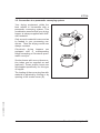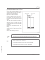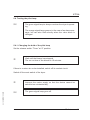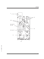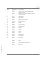
1
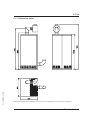
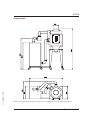
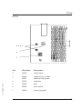
Operating Instructions
64.10-0067GB10 06/00
Dehumidified air dryer
CTT 30
Colortronic GmbH
CTT 30
Colortronic GmbH
Otto-Hahn-Straße 10-14
61381 Friedrichsdorf
USA
Colortronic, Inc.
155 E., 9th Avenue
Runnemede, NJ 08078
Telephone (0 61 75) 7 92-0
Telefax (0 61 75) 7 92-1 79
Email [email protected]
Http://www.colortronic.de
Telephone (856) 312-9600
Telefax (856) 312-9696
Email [email protected]
Technical service:
Service department
Telephone: (0 61 75) 7 92-2 22
Telefax: (0 61 75) 7 92-1 19
Email [email protected]
Spare parts department
Telephone: (0 61 75) 7 92-3 33
Telefax: (0 61 75) 7 92-1 08
Edition: 06/00
Order-No: 64.10-0067GB10
These operating instructions are for*:
(* Please fill in personally)
Serial number:
Year of manufacture:
Date of delivery:
64.10-0067GB10 06/00
Number of delivery:
Date of commissioning:
Location:
Group of machines:
2
CTT 30
64.10-0067GB10 06/00
Colortronic GmbH retains all rights to change the information in these operating
instructions at any time without notice.
We assume no liability for any errors or direct or indirect damage resulting in context with these operating instructions.
Copying, translation or publication in any form except for personal use of purchaser requires approval from Colortronic GmbH.
All rights reserved.
3
CTT 30
Table of contents
1. Safety instructions . . . . . . . . . . . . . . . . . . . . . . . . . . . . . . . . . . . . . . . . . . . . 7
1.1.
1.2.
1.3.
1.4.
Warnings and symbols . . . . . . . . . . . . . . . . . . . . . . . . . . . . . . . . . . 8
Explanations and information . . . . . . . . . . . . . . . . . . . . . . . . . . . . . 9
For your safety. . . . . . . . . . . . . . . . . . . . . . . . . . . . . . . . . . . . . . . . 10
Equipment Safety . . . . . . . . . . . . . . . . . . . . . . . . . . . . . . . . . . . . . 14
2. Assembly instructions . . . . . . . . . . . . . . . . . . . . . . . . . . . . . . . . . . . . . . . . 16
2.1.
2.2.
2.3.
2.4.
2.5.
Transport . . . . . . . . . . . . . . . . . . . . . . . . . . . . . . . . . . . . . . . . . . . . 17
Installation . . . . . . . . . . . . . . . . . . . . . . . . . . . . . . . . . . . . . . . . . . . 18
Installation of the exhauster fan for regeneration of exhaust air 19
Electrical connection . . . . . . . . . . . . . . . . . . . . . . . . . . . . . . . . . . . 20
Connecting the return air cooler (optional) . . . . . . . . . . . . . . . . . 21
3. Functional description . . . . . . . . . . . . . . . . . . . . . . . . . . . . . . . . . . . . . . . . 22
3.1. General information . . . . . . . . . . . . . . . . . . . . . . . . . . . . . . . . . . . . 23
3.2. Drying hopper (optional) . . . . . . . . . . . . . . . . . . . . . . . . . . . . . . . . 25
3.2.1. Hopper heating system . . . . . . . . . . . . . . . . . . . . . . . . . 26
3.3. Connection to a pneumatic conveying system . . . . . . . . . . . . . . 27
3.4. Return air cooler (optional) . . . . . . . . . . . . . . . . . . . . . . . . . . . . . . 28
64.10-0067GB10 06/00
4. Start up . . . . . . . . . . . . . . . . . . . . . . . . . . . . . . . . . . . . . . . . . . . . . . . . . . . . . 29
4.1. Initial start-up . . . . . . . . . . . . . . . . . . . . . . . . . . . . . . . . . . . . . . . . . 30
4.1.1. Switching on the dryer . . . . . . . . . . . . . . . . . . . . . . . . . . 30
4.2. Continuous Operation . . . . . . . . . . . . . . . . . . . . . . . . . . . . . . . . . . 32
4.2.1. Switching the Dryer on . . . . . . . . . . . . . . . . . . . . . . . . . 32
4.2.2. Setting the drying temperature . . . . . . . . . . . . . . . . . . . 33
4.3. Switching the Dryer off . . . . . . . . . . . . . . . . . . . . . . . . . . . . . . . . . 34
4.4. Indication of malfunctions . . . . . . . . . . . . . . . . . . . . . . . . . . . . . . . 35
4
CTT 30
5. Maintenance . . . . . . . . . . . . . . . . . . . . . . . . . . . . . . . . . . . . . . . . . . . . . . . . . 36
5.1.
5.2.
5.3.
5.4.
Maintenance schedule . . . . . . . . . . . . . . . . . . . . . . . . . . . . . . . . . 38
Cleaning/changing the air filters . . . . . . . . . . . . . . . . . . . . . . . . . . 39
Disposal of drying agents . . . . . . . . . . . . . . . . . . . . . . . . . . . . . . . 41
Testing the pilot lamp . . . . . . . . . . . . . . . . . . . . . . . . . . . . . . . . . . 42
5.4.1. Changing the bulb of the pilot lamp . . . . . . . . . . . . . . . 42
5.5. Cleaning drying hoppers . . . . . . . . . . . . . . . . . . . . . . . . . . . . . . . . 44
6. Technical data . . . . . . . . . . . . . . . . . . . . . . . . . . . . . . . . . . . . . . . . . . . . . . . 46
6.1. CTT 30 . . . . . . . . . . . . . . . . . . . . . . . . . . . . . . . . . . . . . . . . . . . . . . 46
6.1.1. Dimension sheet . . . . . . . . . . . . . . . . . . . . . . . . . . . . . . 47
7. Annex . . . . . . . . . . . . . . . . . . . . . . . . . . . . . . . . . . . . . . . . . . . . . . . . . . . . . . 49
7.1. Spare parts list. . . . . . . . . . . . . . . . . . . . . . . . . . . . . . . . . . . . . . . . 50
7.2. Electrical manual . . . . . . . . . . . . . . . . . . . . . . . . . . . . . . . . . . . . . . 54
o Connection diagram no.: _ _ _ _ _ _ _ _ _ _ _ _ _ _ _ _ _ _ _ _ _ _ _
o Currently not available; will be delivered at a later date !
7.3. Accessories . . . . . . . . . . . . . . . . . . . . . . . . . . . . . . . . . . . . . . . . . . 55
o Basic setting thermo regulator _ _ _ _ _ _ _ _ _ _ _ _ _ _ _ _ _ _ _ _ _
o ________________________________________
64.10-0067GB10 06/00
o ________________________________________
5
CTT 30
1. Safety instructions
»
These safety instructions apply to all persons within the range of
action of the equipment.
Please inform all persons within the range of action of the equipment of the direct and indirect hazards connected with the
equipment.
These operating instructions are to be used by all persons assigned activities connected with the equipment.
Knowledge of the English language is prerequisite.
64.10-0067GB10 06/00
Ensure in each case that the operating personnel are familiar
with the operating instructions and the function of the equipment.
Safety instructions 6
CTT 30
1.1. Warnings and symbols
The following warnings and symbols are used in these operating instructions:
»
This symbol indicates danger to life! Fatal or serious injury is
possible if the corresponding instructions, regulations or warnings are not observed.
This symbol indicates that serious injury is possible if the corresponding instructions, regulations or warnings are not observed.
F
This symbol indicates that extensive damage to equipment is
possible if the corresponding instructions, regulations or
warnings are not observed.
&
This symbol indicates information important for becoming familiar with the equipment, i.e. technical correlations.
$
This symbol indicates that a technical term is explained at
this point.
64.10-0067GB10 06/00
L
Safety instructions 7
CTT 30
1.2. Explanations and information
Various terms and designations are used in these operating instructions to ensure clarity. Therefore please note that the terms used in the text stand for the
corresponding explanations listed below.
· Equipment
“Equipment” can mean an individual unit, a machine or an installation.
personnel
· Operating
The “operating personnel” are persons operating the equipment on their own responsibility or according to instructions.
· Operator
The “operator” of the equipment (production manager, foreman, etc.) is the person responsible for all production sequences. The operator instructs the operating personnel of what is to be done.
instructions
· Operating
The “operating instructions” describe the interaction of the equipment, production
sequences or methods. The operating instructions must be compiled by the operator of the equipment.
foreman
· Equipment
When several operating personnel work on one machine, the “equipment foreman” coordinates the sequences. The equipment foreman must be appointed by
the operator.
personnel
· Trained
“Trained personnel” are persons who, due to their training, are authorized to carry
64.10-0067GB10 06/00
out the required work.
Safety instructions 8
CTT 30
1.3. For your safety
· The operator of this machine must be at least 16 years old.
these operating instructions carefully before the initial start-up. Observe all
· Read
points. Contact us if anything is unclear.
This avoids injury and damage to equipment!
instructions must be stored in such a way that they are available at all times
· These
at the place of operation of the machine.
Danger of accidents arising through improper use!
note that for reasons of clarity not every conceivable case of operation or
· Please
of maintenance can betaken into consideration.
all safety and hazard warnings on the equipment.
· Observe
This avoids injury and damage!
all work on the machine to be carried out only by persons whose qualifica· Allow
tions are set out in the relevant chapters of the operating instructions.
Danger of accidents from improper use!
all work carried out on the equipment only the prescribed working clothes
· For
should be worn. This avoids injury!
the electric supply values with those of the mains supply.
· Compare
Danger of accidents from electric shock!
64.10-0067GB10 06/00
using lifting gear, please observe the relevant regulations.
· When
Danger of accidents!
local regulations and requirements pertaining to the equipment must be ob· The
served.
electrical components from the mains supply before work is carried
· Disconnect
out on these components. Danger to life and limb from electric shock!
Safety instructions 9
CTT 30
not modify, add other equipment or change the design of the equipment with· Do
out the approval of the manufacturer. Danger of accidents!
detailed operating instructions based on the operating instructions sup· Compile
plied for the sequence of procedures to be carried out on this machine.
Danger of accidents from improper use!
· Appoint a machine foreman to be responsible for the machine.
that the operating staff are thoroughly trained in the operation of the
· Ensure
equipment. Danger of accidents from improper use!
the machine is switched off for safety reasons, it must be secured against un· Ifauthorised
activation. Danger of accidents!
· Before starting maintenance work, appoint a supervisor.
the staff responsible before starting maintenance work.
· Inform
Danger of accidents!
the equipment from the mains supply before starting maintenance
· Disconnect
work to ensure that it cannot be switched on accidentally.
Danger of accidents!
· Repair work may be carried out only by trained staff! Danger of accidents!
64.10-0067GB10 06/00
operate the equipment when it is partly dismantled!
· Never
Danger! Limbs may be caught in machinery! Electric shock!
machine may only be operated when all the associated components are
· The
properly connected up and in accordance with the relevant regulations.
case of malfunction, shut down the equipment immediately. Have faults cor· Inrected
immediately. Danger of accidents!
Safety instructions 10
CTT 30
machine is intended only for the drying of granulated plastics. Any other or
· The
additional use is contrary to specifications.
· This machine is not suitable for food-drying.
note that sound levels exceeding 85 db(A) may in the long term damage
· Please
your health. Use the appropriate ear muffs. This avoids impairment of hearing!
not supplied by Colortronic must be manufactured in accordance
· Attachments
with safety regulation EN 294. Danger of accidents!
pipes, hoses and screwed connections should be checked regularly for leaks
· All
and damage. Any faults which arise should be corrected immediately.
Danger of accidents!
· The safety instructions of the connected machines must be followed.
return air filter should only be cleaned/replaced when the the main switch is
· The
off and the blower has stopped. This avoids injury and damage to equipment!
operate the dryer without side panels.
· Never
Danger: Limbs may be caught in machinery! Injury through burns!
drying plastics which emit gases dangerous for human health, take care
· When
that the regeneration exhaust air is disposed of without polluting the environment.
· Open drying hoppers only if they are completely empty.
64.10-0067GB10 06/00
open drying hoppers while the device is in operation.
· Never
Danger: Injury through burns!
drying hoppers only if they have been cooled down sufficiently.
· Open
Danger: Injury through burns!
· Remove any granules remaining on the ground. Danger of accidents!
Safety instructions 11
CTT 30
the wheels after installation if the dryer is mounted on a movable frame.
· Arrest
This will prevent danger to people and material!
care that the device is not standing on the mains cable.
· Take
This will prevent danger to people and material!
note that the drying cells, drying hoppers and air pipings grow hot during
· Please
use. Avoid touching any of these parts! Danger: Injury through burns!
64.10-0067GB10 06/00
the dryer only if there is at least one drying hopper operating.
· Operate
This will prevent damage of material!
Safety instructions 12
CTT 30
1.4. Equipment Safety
should never be changed unless the precise consequences can be as· Settings
sessed.
· Only original Colortronic spare parts should be used.
· Please follow the maintenance instructions.
· A record should be kept of all maintenance and repair work.
note that electronic sub-assemblies can be damaged by static dis· Please
charges.
the initial start-up and at regular intervals all electrical connections should
· Before
be checked to see if they fit securely.
· Never adjust sensors without knowing exactly what their function is.
be noted that the maximum ambient temperature should not exceed
· It35should
°C.
· The drying hoppers should be cleaned before they are filled for the first time.
manufacturers’ specifications re maximum drying temperature should be ob· The
served.
64.10-0067GB10 06/00
· The manufacturers’ drying instructions must be followed.
ensure that the drying hoppers are always completely filled and that the
· Please
dwelling time is adhered to during continual removal.
note that if too great quantities are removed from the drying hopper this
· Please
may lead to insufficient drying of the material.
Safety instructions 13
CTT 30
· The air slide valves of unused or empty drying hoppers should be closed.
· Please make a note of all data entered in the control system.
· Drying agents must be disposed of in accordance with all official regulations.
· Ensure that drying cells are exchanged by Colortronic or refilled only when empty.
· Please note that the dryer must not be tilted or laid on its side.
return air filters are to be cleaned/replaced only when the main switch is off
· The
and the blowers have stopped.
equipment should be operated only when the hopper(s) is/are sufficiently
· The
filled with material.
64.10-0067GB10 06/00
operating instructions of the machines to which it is connected should be
· The
obeyed.
Safety instructions 14
CTT 30
2. Assembly instructions
»
These installation instructions are intended for persons with
skills in electrical and mechanical areas due to their training, experience and received instructions.
Personnel using these installation instructions must be instructed in the regulations for the prevention of accidents, the
operating conditions and safety regulations and their implementation.
Ensure in each case that the personnel are informed.
The installation instructions provided in the corresponding operating instructions apply for all connected equipment.
Observe safety regulations with regard to lifting gear handling
All installation work must be carried out with the equipment disconnected from electrical power and compressed air supply.
L
For installation work taking place at heights of over approx. 6
feet, use only ladders or similar equipment and working platforms intended for this purpose. At greater heights, the
proper equipment for protection against falling must be worn.
The installation instructions provided in the corresponding
operating instructions apply for all connected equipment.
64.10-0067GB10 06/00
Use suitable workshop equipment.
F
Install the equipment such that all parts are easily accessible;
this facilitates maintenance and repair work.
Assembly instructions 15
CTT 30
2.1. Transport
The dryer or the compact unit is delivered on a pallet.
The dryer should only be moved by means of the appropriate lifting equipment
(e.g. a fork lift).
»
All safety regulations regarding work with lifting equipment
should be obeyed.
The machine must not be tilted or laid on its side.
64.10-0067GB10 06/00
F
Attention should be paid to the load capacity of the lifting equipment.
Assembly instructions 16
CTT 30
2.2. Installation
Because of its compact construction the dryer can be installed directly beside the processing machine (drying hopper on the processing machine) or supplied with a
drying hopper as a mobile attachment (compact unit).
Special foundations are not necessary for installation.
The dryer must be installed on a
level surface and must not be exposed to excessive humidity. The
maximum permissible ambient
temperature is 35 °C.
Compact unit
To facilitate servicing, the dryer should be installed in such a way that that it is accessible from 3 sides.
»
F
The main switch must be freely accessible.
The equipment must not be tilted or laid on its side.
To conserve energy, keep the distance between dryer, hopper and processing
machine as small as possible.
The wheels of the compact unit should be locked to ensure stable installation.
64.10-0067GB10 06/00
The foil should be removed from the drying hopper.
Assembly instructions 17
CTT 30
2.3. Installation of the exhauster fan for regeneration of exhaust air
64.10-0067GB10 06/00
When plastics are being dried that release harmful gases during the drying process, care must be taken that the regeneration exhaust air is disposed of in an environmentally sound way. At the same time the throughput of the regeneration
blower must not be altered. It should be noted when assembling a disposal system (e.g. an exhauster system) that the regeneration exhaust air is very humid.
Thus condensation may form, which must not under any circumstances return to
the dryer.
Assembly instructions 18
CTT 30
2.4. Electrical connection
»
The electrical connection may only be carried out by Colortronic
Service Staff or trained personnel authorised by Colortronic.
It is not permitted for other persons to undertake the electrical
connection.
The regulations of the local electrical supply company must be
observed.
F
All the electrical connections and electrical screwed connections must be checked regularly to see if they fit securely.
Before plugging in the mains plug, ensure that the main
switch is in position “0".
The connected load is approximately 2.1 kW.
The operating voltage is 220-240 V/50 Hz.
Special voltages on request.
Connect the mains plug to a mains socket.
64.10-0067GB10 06/00
The fuse must be 16 A.
Assembly instructions 19
CTT 30
2.5. Connecting the return air cooler (optional)
F
A return air cooler must be installed if the return air temperature exceeds 65 °C.
The return air cooler may be connected to a coolant circuit or the water mains network.
The rate of flow at the water mains network is approximately 0.15 m3/h.
The dimensions of the coolant circuit should be designed accordingly.
Connect the coolant intake and return line to the return air cooler.
The direction of flow of the coolant should be noted.
Check the connections for leaks.
Coolant outlet port
64.10-0067GB10 06/00
Coolant inlet port
Return air cooler
Assembly instructions 20
CTT 30
3. Functional description
»
This functional description is addressed to the operators of the
equipment.
This functional description assumes general familiarity with drying equipment.
64.10-0067GB10 06/00
It should be verified that the operators do indeed have the appropriate skills.
Functional description 21
CTT 30
3.1. General information
The dehumidified air dryer CTT 30
has been developed for the drying
of plastic granules. Because of its
compact construction it can be installed directly beside the processing machine (with the drying hopper
on the processing machine) or with
a drying hopper as a mobile attachment (compact unit).
The dryer works on the principle of
dehumidified air, i.e. the air is not
only heated but also dehumidified
before flowing into the drying hopper.
Compact unit
This principle allows plastic granules to be dried to a very low residual moisture content.
The drying temperature is adjustable. If need be, the dehumidified air can be
heated to a maximum temperature of 180 °C (upper limit). Because of the heat released when the water is absorbed in the drying cells the lower limit value of the
dehumidified air temperature is approximately 70 °C.
The drying process is continuous, i.e. there are no rest periods as a result of the
regeneration of the drying agent.
64.10-0067GB10 06/00
F
The dryer is designed for continuous operation.
The dryer must only be started up if the drying hopper is full.
All operations are fully automatic.
Functional description 22
CTT 30
The dryer is equipped with 2 drying cells. One drying cell is part of the in the drying
circuit, the other drying cell is being regenerated at the same time.
A portion of the dehumidified air is available for the regeneration of the damp drying cell. This air is heated up by the regeneration heater at the start of the regeneration. After the heating period the drying cell is cooled off with dehumidified air.
After the switch-over time is reached, the regenerated drying cell is introduced
into the drying circuit and the cycle begins again.
1
2
3
4
5
6
7
8
9
Drying cell
Regenerating heater
Drying hopper
Diaphragm
Return air filter
Blower
Valve
Drying heater
Suction box
64.10-0067GB10 06/00
Functional diagram
Functional description 23
CTT 30
3.2. Drying hopper (optional)
The material is dried in the drying
hopper. The dehumidified air is
forced through the material in the
hopper and absorbs the humidity in
the process. The size of a drying hopper must correspond to the intended
application, to ensure that the desired final moisture content is attained.
When a drying hopper is refilled the
material must first of all be completely
dried before material can be removed
for the first time.
When material is continuously being
removed from the hopper, material
must also be continuously fed into the
hopper (continuous drying). The new
(damp) material is fed into the drying
hopper from the top and slowly
moves downwards towards the material suction box. The material moves
downwards until its final moisture
content is attained.
Drying hopper
64.10-0067GB10 06/00
To guarantee continuous drying we
recommend keeping the drying hopper always completely filled.
Functional description 24
CTT 30
3.2.1. Hopper heating system
Every drying hopper has its own hopper heating system. The temperature of the
dehumidified air is set on the temperature controller. The setting range extends
from 60-180 °C. The current temperature can be read on the digital display (actual value).
F
The thermo regulator is factory-programmed. Nevertheless,
you have to set specific values which are dependent on the
processed material.
Process display
drying temperature
60
180
Setpoint display
drying temperature
“PGM” key,
Selecting operating level
or parameter selection
PGM
reducing setpoint value
K1 K2
K3
EXIT
“EXIT” key,
Aborting the input
increasing setpoint value
64.10-0067GB10 06/00
Thermo regulator
Functional description 25
CTT 30
3.3. Connection to a pneumatic conveying system
Your drying equipment yields the
best results in connection with a
pneumatic conveying system. This
combination ensures that your drying
hopper is always supplied with sufficient material.
Only as much material is removed as
is needed in your processing machines. Thus the drying results are
always constant.
A
Colortronic drying hoppers are
equipped with a corresponding
flange accepting a Colortronic pneumatic conveyor.
Suction boxes with one or three suction tubes can be supplied as well
(optional). These suction boxes are
developped specifically for this type
of hopper.
Suction box
64.10-0067GB10 06/00
The loading of the conveying line with
material is adjusted by closing or by
opening of the control cover (A).
Functional description 26
CTT 30
3.4. Return air cooler (optional)
F
A return air cooler must be used when the return air temperature is over 65 °C.
A return air cooler improves the efficiency of the drying cells.
F
The lower the reading chosen for the return air temperature,
the better the efficiency of the drying cells.
64.10-0067GB10 06/00
The return air cooler can be connected to a coolant circuit or to the water mains
network.
Functional description 27
CTT 30
4. Start up
»
This chapter is addressed to the operators of the machine.
This chapter assumes general skills with drying equipment.
This chapter assumes that the functional description has been
read and understood.
It must be ensured that the operators have the required experience.
F
Check that the main switch is in position “0".
Check whether the release switch “Timer” is at ”0" position.
Check the drying hopper for cleanliness.
Check to see whether the adhesive film on the drying
hopper has be removed.
If there is a return air cooler, switch on its coolant circuit.
When the dryer is switched on and when the valve block is
changed, the orange signal lamp lights up briefly.
64.10-0067GB10 06/00
&
Start up 28
CTT 30
4.1. Initial start-up
Check whether the inlet of the drying hopper is closed by a blind lid, or whether a
conveyor unit (optional) is installed.
If not, manufacture a suitable blind lid and install it on the inlet of the drying hopper
or install the conveyor unit (optional).
F
Attachments which are not supplied by Colortronic must be
manufactured according to the safety regulation European
Standard 294.
Check whether the coolant circuit of the return air cooler is turned on (if a return
air cooler is installed).
4.1.1. Switching on the dryer
Switch on the dryer at the main switch.
&
The green signal lamp lights up.
For operation without timer clock:
Turn the release switch “Timer” at “I” position.
64.10-0067GB10 06/00
For operation with timer clock (if available, optional):
Turn the release switch “Timer” at “II” position.
&
The blower is running.
Start up 29
CTT 30
F
If the dryer has not been in use for several months it must be
operated for about 2 hours without material.
Turn the thermo regulator to +80 °C for the drying temperature.
Press the “PGM” key.
Set by means of the arrow keys the drying temperature
to “80".
After 2 seconds the display flashes and the value is stored.
Press the “EXIT” key (the setpoint value and the actual value
of the drying temperature are displayed).
EXIT
After 2 hours turn the release switch “Timer” at “0" position.
L
Wait until the blower has stopped.
The run on time of the blower is 10 minutes.
64.10-0067GB10 06/00
If there is a return air cooler installed, switch off its coolant circuit.
Switch off the main switch of the dryer.
&
The green signal lamp goes off.
Start up 30
CTT 30
4.2. Continuous Operation
F
Fill at least half of the drying hopper with material.
4.2.1. Switching the Dryer on
Switch on the main switch of the dryer.
&
The green signal lamp lights up.
For operation without timer clock:
Turn the release switch “Timer” at “I” position.
For operation with timer clock (if available, optional):
Turn the release switch “Timer” at “II” position.
The blower is running.
64.10-0067GB10 06/00
&
Start up 31
CTT 30
4.2.2. Setting the drying temperature
For each drying hopper, set the required drying temperature (= desired value) by
means of the respective thermo regulator.
Check whether the set drying temperature is appropriate for the materials which
have been filled in.
Observe the instructions of the material manufacturer.
After the first filling, process the material only after the retention period is over.
Observe the instructions of the material manufacturer.
Press the “PGM” key.
By means of the arrow keys select the desired value for
the drying temperature.
After 2 seconds the display flashes and the value is stored.
Press the “EXIT” key (the setpoint value and the actual value
of the drying temperature are displayed).
After a change of materials, immediately check and correct
the set drying temperature.
64.10-0067GB10 06/00
F
EXIT
Start up 32
CTT 30
Optimizing the thermo regulator
Press the “EXIT” key for at least 2 seconds until
“tunE” is displayed.
&
EXIT
“tunE” flashes.
The optimization can take several minutes.
If “tunE” stops flashing, the optimization is finished.
Press the “EXIT” key.
4.3. Switching the Dryer off
Set the release switch “Timer” at “0" position.
L
Wait until the blower has stopped.
The run on time of the blower is 10 minutes.
If there is a return air cooler installed, switch off its coolant circuit.
64.10-0067GB10 06/00
Switch off the main switch of the dryer.
&
The green signal lamp goes off.
Start up 33
CTT 30
4.4. Indication of malfunctions
&
Malfunctions are indicated by a steady light signal of the orange lamp.
Malfunctions must be corrected before the control system
can resume operations.
The following malfunctions can set off an alarm:
Blower
The pressure produced by the blower is too low.
Regenerator heater 1
The safety temperature limiter of regeneration heater 1 has been tripped.
Regenerator heater 2
The safety temperature limiter of regeneration heater 2 has been tripped.
Hopper heater
The safety temperature limiter of the hopper heater has been tripped.
When the fault has been repaired the pilot lamp will no longer
be on.
64.10-0067GB10 06/00
&
Start up 34
CTT 30
5. Maintenance
»
This chapter is intended for persons with skills in electrical and
mechanical areas due to their training, experience and received
instructions.
Personnel using the instructions in this chapter must be instructed of the regulations for the prevention of accidents, the
operating conditions and safety regulations and their implementation.
Ensure in each case that the personnel are informed.
For maintenance work taking place at theights of over approx. 6
feet, use only ladders or similar equipment and working platforms intended for this purpose. At greater heights, the proper
equipment for protection against falling must be worn.
Use only suitable lifting gear which is in proper working order
and load suspension devices with sufficient carrying capacity.
Do not stand or work under suspended loads!
Ensure that the electric motors/switch cabinets are sufficiently
protected against moisture.
Use suitable workshop equipment.
Before starting maintenance work, appoint a supervisor.
Inform the responsible personnel before maintenance work on
the system is started.
64.10-0067GB10 06/00
Never operate the equipment when partially dismantled.
Any maintenance and repair work NOT described here may only
be carried out by Colortronic service personnel or by specialised staff authorised by Colortronic.
Maintenance 35
CTT 30
L
Disconnect the equipment from mains supply before starting
mainenance procedures to ensure that it cannot be switched
on unintentionally.
All compressed air pipes on the equipment should be depressurised before starting maintenance work.
F
Please observe the maintenance schedule.
Before starting maintenance work, clean the equipment of
oil, fuel or lubricant.
Ensure that materials and incidentals required for operation
as well as spare parts are disposed of properly and in an environmentally sound manner.
Use only original Colortronic spare parts.
64.10-0067GB10 06/00
Keep record of all maintenance and repair procedures.
Maintenance 36
CTT 30
5.1. Maintenance schedule
Daily:
Check warning signs on equipment for good
legibility and completeness
Clean return air filters and casing
(depending on dust build-up)
Weekly:
Check main switch for proper function
Check the signal lamps for proper function
Every six months:
Change return air filters
(depending on dust build-up)
All electrical and mechanical connections
should be checked to see if they fit securely
Annually:
Dewpoint should be checked (only by
Colortronic service personnel)
Whenever the
material is changed:
The drying hopper and suction box must
be cleaned
&
The service intervals refer to a 3-shift operation.
F
The given maintenance intervals are average values.
64.10-0067GB10 06/00
Check whether in your individual case the maintenance intervals must be shortened.
Maintenance 37
CTT 30
5.2. Cleaning/changing the air filters
Set the release switch “Timer” at “0" position.
L
Wait until the blower has stopped.
The run on time of the blower is 10 minutes.
If there is a return air cooler installed, switch off its coolant circuit.
Switch off the main switch of the dryer.
L
Interrupt the mains supply so that the device cannot be
switched on unintentionally.
&
The green signal lamp goes off.
64.10-0067GB10 06/00
Clogged filters substantially reduce the amount of circulating
air and lead to a production lag of your dryer. Clogged filters
may also damage the heating elements.
Maintenance 38
CTT 30
Cleaning/changing return air filters
Detach the retaining clamps on the
casing of the return air filter and remove the lid of the casing.
retaining clamp
return air filter
Remove the filter cartridge.
Clean the inside of the return air filter casing. Fibre-free tissues or an
industrial vacuum cleaner should be
used.
The dirty filter cartridge should be
aspirated from the inside out with
compressed air or the filter cartridge
changed.
Insert the cleaned/new filter cartridge.
Install the lid of the return air filter
casing.
Secure the retaining clamps.
CTT 30
F
The dryer should never be operated without return air filters.
&
Order numbers return air filters
for operation without a return air cooler: ID 85685
64.10-0067GB10 06/00
for operation with a return air cooler: ID 85684
Maintenance 39
CTT 30
5.3. Disposal of drying agents
Care should be taken that drying cells are changed or refilled by Colortronic only
when empty.
Drying agents should be disposed of only in accordance with
all official regulations.
Used drying agents should be disposed of as special waste,
as they can be contaminated with foreign matter from the
dried materials.
Colortronic cannot take back the used drying agents or the
drying cells with used drying agents.
64.10-0067GB10 06/00
&
Maintenance 40
CTT 30
5.4. Testing the pilot lamp
&
The green signal lamp is always on when the dryer is operating.
The orange signal lamp goes on in the case of an alarm message, but can also flash shortly when the valve block is
changed.
5.4.1. Changing the bulb of the pilot lamp
Set the release switch “Timer” at “0" position.
L
Wait until the blower has stopped.
The run on time of the blower is 10 minutes.
If there is a return air cooler installed, switch off its coolant circuit.
64.10-0067GB10 06/00
Switch off the main switch of the dryer.
L
Interrupt the mains supply so that the device cannot be
switched on unintentionally.
&
The green signal lamp goes off.
Maintenance 41
CTT 30
Open the front ring.
Remove the green/orange
spherical cap.
Spherical cap
Replace the bulb.
Front ring
Fix the green/yellow spherical cap.
Fix the front ring.
Signal lamp
&
Purchase order number
ID 85945
64.10-0067GB10 06/00
bulb:
Maintenance 42
CTT 30
5.5. Cleaning drying hoppers
Set the release switch “Timer” at “0" position.
L
Wait until the blower has stopped.
The run on time of the blower is 10 minutes.
If there is a return air cooler installed, switch off its coolant circuit.
Switch off the main switch of the dryer.
L
Interrupt the mains supply so that the device cannot be
switched on unintentionally.
&
The green signal lamp goes off.
F
Clean the drying hopper each time you are changing the materials.
Make sure that the drying hopper has cooled down sufficiently.
Make sure that the drying hopper is completely empty.
64.10-0067GB10 06/00
Remove any granules remaining on the ground.
Maintenance 43
CTT 30
Open the cleaning opening of the drying hopper at the handle (A).
Clean the drying hopper.
Close the cleaning opening of the drying hopper.
F
Remove any granules remaining in the cleaning opening.
64.10-0067GB10 06/00
A
TT 60 - TT 1600
Maintenance 44
CTT 30
6. Technical data
6.1. CTT 30
Dehumidified air throughput: . . . . . . . . . . . . . . . . . . . . . . . . . . . . max. 30 m3/h
Operating voltage: . . . . . . . . . . . . . . . . . . . . . . . . . . . . . . . . . . 220-240 V/50 Hz
Special voltage by request
Connected load: . . . . . . . . . . . . . . . . . . . . . . . . . . . . . . . . . . . . . . . . . . . . 2.1 kW
Calorific output (drying): . . . . . . . . . . . . . . . . . . . . . . . . . . . . . . . . . max. 1.5 kW
Calorific output (regenerating): . . . . . . . . . . . . . . . . . . . . . . . . . . max. 0.45 kW
Drive power (drying/regenerating): . . . . . . . . . . . . . . . . . . . . . . . . . . . . . 0.1 kW
Drying temperature: . . . . . . . . . . . . . . . . . . . . . . . . . . . . . . . . . . . . max. 180 °C
Width: . . . . . . . . . . . . . . . . . . . . . . . . . . . . . . . . . . . . . . . . . . . . . . . . . . . 450 mm
Depth: . . . . . . . . . . . . . . . . . . . . . . . . . . . . . . . . . . . . . . . . . . . . . . . . . . . 520 mm
Height:. . . . . . . . . . . . . . . . . . . . . . . . . . . . . . . . . . . . . . . . . . . . . . . . . . 1170 mm
Weight of CTT 30: . . . . . . . . . . . . . . . . . . . . . . . . . . . . . . . . . . . . . approx. 80 kg
64.10-0067GB10 06/00
Noise level: . . . . . . . . . . . . . . . . . . . . . . . . . . . . . . . . . . . . . . . approx. 70 dB (A)
Technical data 45
CTT 30
64.10-0067GB10 06/00
6.1.1. Dimension sheet
Dimensions and data without obligation. Dimensions in mm. Specifications may be subject to alterations.
Technical data 46
CTT 30
64.10-0067GB10 06/00
Compact unit
Dimensions and data without obligation. Dimensions in mm. Specifications may be subject to alterations.
Technical data 47
CTT 30
64.10-0067GB10 06/00
7. Annex
Annex 48
CTT 30
7.1. Spare parts list
Other persons are not permitted to modify or repair the equipment.
64.10-0067GB10 06/00
»
This spare parts list is intended to be used only by trained personnel.
Annex 49
CTT 30
CTT 30
2, 3, 4, 5
6
64.10-0067GB10 06/00
7
Pos.
ID-number
Description
2
85942
lamp bottom
3
85943
85247
spherical cap, orange
spherical cap, green
4
87452
fastening
5
85945
bulb
6
88904
main switch
7
87454
thermo regulator
Annex 50
CTT 30
1
10
8, 9
18, 19, 20
21, 22
16
13, 14, 15
11
64.10-0067GB10 06/00
12
Annex 51
CTT 30
ID-number
Description
1
85684
return air filter, when operating with
return air cooler
85685
return air filter, when operating without
return air cooler
8
94233
sealing ring
9
93298
hose clamp
10
21041
sealing valve housing
11
83339
pressure switch
12
85693
blower
13
85280
motor operator
14
21032
valve housing
15
21033
spindle
16
30957
control
18
85692
heater
19
23219
sieve
20
85690
sealing ring
21
85691
hose clamp
22
96196
desiccant
85689
base
85819
guide roll with fixing device
85820
guide roll
64.10-0067GB10 06/00
Pos.
Annex 52
CTT 30
7.2. Electrical manual
»
This electrical manual is intended to be used only by Colortronic
service personnel and trained personnel authorized by
Colortronic.
Other persons are not permitted to modify or repair the equipment.
o Connection diagram no.: _ _ _ _ _ _ _ _ _ _ _ _ _ _ _ _ _ _ _ _ _ _ _
64.10-0067GB10 06/00
o Currently not available; will be delivered at a later date !
Annex 53
CTT 30
7.3. Accessories
o Basic setting thermo regulator _ _ _ _ _ _ _ _ _ _ _ _ _ _ _ _ _ _ _ _ _
o ________________________________________
64.10-0067GB10 06/00
o ________________________________________
Annex 54
CTT 30
Basic setting thermo regulator
»
This information is intended to be used only by Colortronic service personnel and trained personnel authorized by Colortronic.
Other persons are not permitted to modify or repair the equipment.
Code
C111
0
0
0
0
C112
6
0
0
0
C113
0
0
3
4
C114
1
0
0
1
SPL
0
0
4
0
SPH
0
1
8
0
Parameter set 1
AL1
20.0
HYS1
1
rASd
10.0
64.10-0067GB10 06/00
Parameter
Annex 55