1
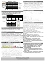
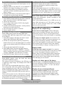
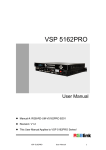
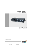
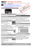
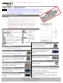
VIEWSIZE THE WORLD
VSP 5360 – Quick Start
NOTE
For full installation, configuration, and operation details, please refer to
VSP 5360 user manual, which is available at www.rgblink.com.
This quick start provides basic instructions for an experienced installer
to set up and operate VSP 5360.
Installation and Cabling
Back Panel
Interfaces
Displayport input
20 21
5 6 10 11 10/100M Interface RJ45 22 23 24 DVI input
USB Interface
SDI input
25
RS232 Interface
SDI loop out
26
12 Power supply port of sending card 27 28 29 Program output
13 USB control port of sending card 30
Preview output
DVI
input
port
of
sending
card
Switch
31
14
Power IEC-3 Step 7-SDI Loop Out
15 16 17 CVBS input BNC port
32
port
18 19
VGA input
Can connect the next level VSP 5360 or
Step 1-Mounting
the device with SDI input.
Turn off all equipment power sources.
Step 8-Preview VGA Output
1
2
3
4
7
8
9
Dial Switch
Step 2-CVBS Input
Connect NTSC, PAL or SECAM component
video to these female BNC connectors.
Step 3-SDI Input
Input video signals from HD player or HD
c am e r a a nd s o on, support 3G/HD/SDSDI.
Step 4-DVI Input
Input signals from DVI signal generator
or computer with DVI port.
Step 5-VGA Input
Input signal from VGA signal generator,
such as PC or laptop.
Step 6-Displayport Input
Input the video signal from HD player,
computer.
Connect display projectors and other
equipment with standard VGA
interface.
Step 9-Program DVI Output
DVI output is used to connect DVI
display and LED control system, etc.
Step 10-USB Connector
Connect VSP 5360 to PC via USB cable for
windows control.
Step 11-LAN (Ethernet) Port
Use CAT5 crosswire as the picture shows. The default
IP address is 192.168.0.100. User can change the IP
address via RS232 or USB port.
CAT5 crosswire is one end in T568A standard, the
other in T568B standard.
LAN (Ethernet) port is not standard configuration
module.
Mega Systems Inc., US Distributor of RGBLink
Address:S603-604 Weiye Building Torch Hi-Tech Industrial Development Zone Xiamen,Fujian Province, P.R.C
www.megasystemsinc.com • [email protected]
Tel: 00865925771197
Fax:00865925771202
Toll Free: 866-460-MEGA • Local: 210-684-2600
Email: [email protected]
http://www.rgblink.cn
5718 Kenwick St., San Antonio, TX 78238
VSP 5360 Quick Start
Version 1.1
Page 1 of 4
End terminal
How to Add or Clear the Layer
Definition of crosswire
Pin
T568A cable end
color
T568B cable end
color
1
2
3
4
5
6
7
8
White-green
Green
White-green
Blue
White-blue
White-orange
White-brown
Brown
White-orange
Orange
White-green
Blue
White-blue
green
White-brown
Brown
T568A
CAT5
crosswire is
one end in
T568A
standard, the
other in
T568B
standard.
T568B
How to Scale the Image
Step 12-Serial Port
Connect the back panel RJ11 port and RS232 port to
a control system on computer with RS232-to-RJ11
cable. Below is the definition.
Insert a
crosswire into
RS232/RS422
port
Pin
RS-232
Function
RS-422
Function
2
3
5
7
8
TX
RX
GND
-----
Transmit
Receive
Ground Signal
Not used
Not used
TXRXGND
RX+
TX+
Transmit(-)
Receive(-)
Ground Signal
Receive(+)
Transmit(+)
Pin
RJ-11
Function
1
2
3
4
--RX
TX
GND
Not used
Receive
Transmit
Ground Signal
Push [Scale/Position] button, and enter the SCALE
menu, button 0-9 lights are on, user can input the
number or rotate the knob to set the vertical size and
horizontal size.
SCALE menu are as follows:
H SIZE: Width setting.
V SIZE: Height setting.
RESET: If quality image distorts by mistake in
improper operation, it can be initialized operation to
recover factory setting.
How to Zoom the Image
Insert a
crosswire to
RJ11 port
Step 13-Power
Plug in power cord with IEC connector, VSP 5360
supports AC power from 85~264V AC, 50~60Hz,
which means world wide compatible.
Power On
Push power button to ON position. LCD module on the
front panel will show RGBlink and VSP 5360 model
information, and go into self-verification, then it will load
the last setting configuration data and send the processed
video to target display or device. CV1 input is the default
input source. User can operate VSP 5360 with front panel
buttons or remote control with windows control software
run on computer, by RS232, USB or TCP/IP port.
Local Control
1. In EFFECTS area, add the layer according to actual
need, that is push any key of layer A, B, C, D (or
select all the 4 keys), key lights and flashes means
the layer is selected, and add layer finished.
2. In EFFECTS area, push any key of layer A, B, C, D
that need to clear, key flashes. Push the key again,
key light is off, and clear layer finished.
Front Panel Operation
How to Realize Single Image Switching
1.Boot the system default CV1 to the current input
source (key on and flashes ). If need seamless switch
to other source such as DVI1, push DVI1 key.
2.Push DVI1 buttons, CV1 button is off, and DVI1 key
lights, single image switching (that is switch CV1 to
DVI1) is finished.The same method for CV2, CV3,
VGA1, VGA2, DVI1, DVI2, DVI3, DP1, DP2, SDI1
input signal switching.
Image vertical and horizontal zoom, the effect can
stretch the image according to one direction.
Push [MENU] button, and enter the menu, rotate the
knob and choose [INPUT SETUP], push the knob to
confirm and choose <ZOOM>, push the knob to
confirm, settings are as follows:
V UP: Enlarge the image from the top.
V DOWN: Enlarge the image from the bottom.
V UP/DOWN: Enlarge the image from the top and
the bottom.
H LEFT: Enlarge the image from the left.
H RIGHT: Enlarge the image from the right.
H LEFT/RIGHT: Enlarge the image from the left and
the right.
CENTER: Enlarge the image from the center.
RESET: If quality image distorts by mistake in
improper operation, it can be initialized operation to
recover factory setting
How to Set up the Position of the Image
1. Push [Scale/Position] button two times, the button
lights, user can set up the position of the image.
2. Rotate the knob, and adjust the vertical and
horizontal position.
3. If quality image distorts by mistake in improper
operation, it can be initialized operation to recover
factory setting.
4. Push any other button, [Scale/Position] button light
is off, and close the position setting function.
Mega Systems Inc., US Distributor of RGBLink
Address:S603-604 Weiye Building Torch Hi-Tech Industrial Development Zone Xiamen,Fujian Province, P.R.C
www.megasystemsinc.com • [email protected]
Tel: 00865925771197
Fax:00865925771202
Toll Free: 866-460-MEGA • Local: 210-684-2600
Email: [email protected]
http://www.rgblink.cn
5718 Kenwick St., San Antonio, TX 78238
VSP 5360 Quick Start
Version 1.1
Page 2 of 4
How to Crop the Image
How to Save the Parameter
1. Push [Crop/Zoom] button, the button lights, user can Push SAVE button, the key lights, OLED shows
crop the image.
related save information, operate according to the
2. Rotate the knob to crop H LEFT, V UP, H RIGHT, V prompt information.
DOWN of the image according to user’s need.
Some of the number buttons 0-12 in PRE area are on,
3. If quality image distorts by mistake in improper
and some flash. The buttons on mean there are no save
operation, it can be initialized operation to recover
information, and button flashes will be overwrite. Push
factory setting.
the button on to save, OLED shows save is successful.
4. Push any other button, [Crop/Zoom] button light is
How to Load the Saved Parameter
off, and close crop the image function.
Push LOAD button, the key lights, OLED shows
How to Realize LOGO Capture
related load information, operate according to the
1. Push [MENU] button and enter the menu, rotate the
prompt information.
knob, and select [LOGO CAPTURE] option.
Some of the number buttons 0-12 in PRE area are on,
2. Choose the input source.
some flash and some are off. The button on mean is
3. Freeze image, when capture LOGO, the program
ready for recall. Push the button on to load, OLED
image should be frozen.
shows recall is successful.
4. Set the LOGO horizontal position, vertical position,
Common Questions and Solutions
horizontal size and vertical size.
5. Save the image to LOGO1 or LOGO2.
Display has no output image
6. Start to capture LOGO.
Assure there are input signals: Check if the input
How to Realize DSK Setting
Before DSK setting, please check the DSK input,
currently, DSK input only support DVI3 input, settings
are as follows:
1. Push [DVI3] button, and make sure there is input
signal, and OLED shows DVI3 signal.
2. Set the size and position of [DVI3]. Push [DVI3]
button in Preview area, the button light is on, and the
image can be edited, push [SCALE] button to set the
size.
3. Choose the input signal in Preview area.
4. Push [DSK] button, and start the DSK function.
Rotate the knob and choose <PRESET>, press the
knob to confirm, choose the preset mode of DVI3, for
example, WhOnBk2, press the knob to confirm.
5. Push [SAVE] button, and save the above settings.
signal sources is normal, if normal, please check the
connection; If use PC DVI or VGA as signal source,
please set the display card to dual display or expanding
mode.
Assure there are output signals: Get a monitor with
VGA or DVI port, connect it to device output port, see
if the monitor can display normally. If unnormal,
check if the input signals are connected or if the output
cable contacts good. If normal, check if the sending
card works normally or change a sending card to test.
Display blinks
Check if preview output is normal: Get a monitor
with VGA or DVI port and connect to the device output
port, check if the monitor displays normally. If no
flashes, check if DVI output plugs tight or change the
DVI cable that connects sending card, if the monitor
How to Set up the Screen Parameter
blinks, please check if input signal, input connecting
Push MENU button, rotate the knob and choose cable and input port are normal.
[OUTPUT FORMAT] option.
Display only shows part of the image
The setting of screen is according to the LED size, and
is applied to single image. For example, the LED size Scale the image:Push [Scale /Position] button in the
processor and knob to adjust the actual screen size of
is1408 x 832.
the screen, including “H Size”, “V Size” and “Reset”.
First, choose the resolution that most close to 1408 x
Push the knob to confirm.
832 or larger than 1408 x 832, which ensures that all
image can displayed on the LED screen. Push [MENU] Display shows no bottom half part
button, OLED show the menu, rotate the knob and
Incorrect output resolution: Please make sure the
choose [SCREEN PARAMETERS], push the knob to
points of the screen width and height, choose the
confirm.
resolution to be bigger than screen width via push
Then set H size and V size for 1408 and 832, and need
[MENU] button to find [OUTPUT FORMAT], and
not set the position if image is not migration. If quality
push the knob to confirm.
image distorts by mistake in improper operation, it can
be initialized operation to recover factory setting.
Mega Systems Inc., US Distributor of RGBLink
Address:S603-604 Weiye Building Torch Hi-Tech Industrial Development Zone Xiamen,Fujian Province, P.R.C
www.megasystemsinc.com • [email protected]
Tel: 00865925771197
Fax:00865925771202
Toll Free: 866-460-MEGA • Local: 210-684-2600
Email: [email protected]
http://www.rgblink.cn
5718 Kenwick St., San Antonio, TX 78238
VSP 5360 Quick Start
Version 1.1
Page 3 of 4
Sending card does not support the bottom half
part: TS 802 can control the max horizontal resolution
2048, and vertical resolution 640. Each CAT5 output
is 320 pixels.
All buttons light on together
Check if the dial switch is normal;
Power off the device, check if two red dial switches on
back left part of the device are all upwards, if no, place
them upwards, then power on the device again.
The red dial switches are mainly for upgrade.
Mega Systems Inc., US Distributor of RGBLink
Address:S603-604 Weiye Building Torch Hi-Tech Industrial Development Zone Xiamen,Fujian Province, P.R.C
www.megasystemsinc.com • [email protected]
Tel: 00865925771197
Fax:00865925771202
Toll Free: 866-460-MEGA • Local: 210-684-2600
Email: [email protected]
http://www.rgblink.cn
5718 Kenwick St., San Antonio, TX 78238
VSP 5360 Quick Start
Version 1.1
Page 4 of 4