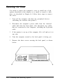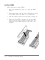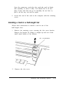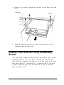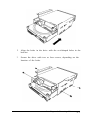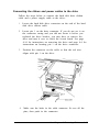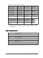
1
EPSON
ACTION PC 2000
USER’S GUIDE
EPSON
®
User’s Guide
Printed on recycled paper with 10% post-consumer content
@
IMPORTANT NOTICE
DISCLAIMER OF WARRANTY
Epson America makes no representations or warranties, either express or implied, by or
with respect to anything in this manual, and shall not be liable for any implied warranties
ofmerchantability and fitness for a particular purpose or for any indirect, special, or
consequential damages. Some states do not allow the exclusion of incidental or
consequential damages, so this exclusion may not apply to you.
COPY RlGHT NOTlCE
All rights reserved. No part of this publication may be reproduced, stored in a retrieval
system, or transmitted, in any form or by any means, electronic, mechanical,
photocopying, recording, or otherwise, without the prior written permission of Epson
America, Inc. No patent liability is assumed with respect to the use of information
contained herein. Nor is any liability assumed for damages resulting from the use of the
information contained herein. Further, this publication and features described herein are
subject to change without notice.
TRADEMARKS
EPSON is a registered trademark of Seiko Epson Corporation
EPSON Connection is a service mark of Epson America, Inc.
General Notice: Other product names used herein are for identification purposes only and
may be trademarks of their respective companies.
Copyright 0 1994 by Epson America, Inc.
Torrance, California, USA
ii
400362700
9/94
Important Safety Instructions
Read all of these instructions and save them for later reference. Follow
all warnings and instructions marked on the computer.
. Unplug the computer before cleaning. Clean with a damp cloth only.
Do not spill liquid on the computer.
. Do not place the computer on an unstable surface or near a radiator
or heat register.
. Do not block or cover the openings in the computer’s cabinet. Do not
insert objects through the slots.
. Use only the type of power source indicated on the computer’s label.
. Connect all equipment to properly grounded power outlets. Avoid
using outlets on the same circuit as photocopiers or air control
systems that regularly switch on and off.
. Do not let the computer’s power cord become damaged or frayed.
. If you use an extension cord
ampere rating of the devices
not exceed the cord’s ampere
devices plugged into the wall
with the computer, make sure the total
plugged into the extension cord does
rating. Also, make sure the total of all
outlet does not exceed 15 amperes.
. Except as specifically explained in this User's Guide, do not attempt
to service the computer yourself.
. Unplug the computer and refer servicing to qualified service
personnel under the following conditions:
If the power cord or plug is damaged; if liquid has entered the
computer; if the computer has been dropped or the cabinet damaged;
if the computer does not operate normally or exhibits a distinct
change in performance. Adjust only those controls that are covered
by the operating instructions.
. If you plan to use the computer in Germany, observe the following:
To provide adequate short-circuit protection and over-current
protection for this computer, the building installation must be
protected by a 16 Amp circuit breaker.
Beim Anschlul3 des Computers an die Netzversorgung muh
sichergestellt werden, dab die Gebaudeinstallation mit einem
16 A Uberstromschutzschalter abgesichert ist.
iii
Importantes instructions de s&wit6
Lire attentivement les instructions suivantes et les conserver pour les
consulter en cas de besoin. Observer soigneusement tous les
avertissements et directives marques sur l’ordinateur.
. Debrancher l’ordinateur avant de le nettoyer. N’utiliser qu’un chiffon
humide. Veiller a ne pas renverser de liquides sur l’appareil.
. Ne pas placer l’ordinateur sur une surface instable ni pres dune
source de chaleur.
. Ne pas bloquer ni couvrir les orifices d’aeration de l’appareil. Ne pas
introduire d’objets dans les ouvertures.
. Utiliser seulement le type de source d’alimentation Clectrique indique
sur l’etiquette.
. Tout l’equipement doit Ctre branche sur des prises de courant avec
contact de terre. Ne jamais utiliser une prise sur le meme circuit
qu’un appareil a photocopies ou un systeme de controle de
ventilation avec commutation marche-arret automatique.
. S’assurer que le cordon d’alimentation de l’ordinateur n’est pas
abime ni effiloche.
. Dans le cas ou on utilise un cordon de rallonge avec l’ordinateur,
s’assurer que l’intensite en amperes requise pour tous les appareils
branches sur ce cordon ne soit pas superieure a la capacite du cordon.
S’assurer aussi que cette intenste ne depasse jamais la somme de 15
amperes pour l’ensemble des appareils.
. Sauf dans les cas specifiques expliques dans ce manuel de l’usager,
ne pas essayer d’entretenir ou de reparer l’ordinateur soi-meme.
. Debrancher l’ordinateur et contacter un technicien qualifie dans les
circonstances suivantes:
Si le cordon ou la prise sont abimes; si un liquide a pen&C a
l’interieur de l’appareil; si on a laisse tomber l’appareil ou si le bonier
est endommage; si l’ordinateur ne fonctionne pas normalement ou
fonctionne dune man&e tres differente de l’ordinaire. N’ajuster que
les commandes d&rites dans les directives.
. Pour utiliser l’ordinateur en Allemagne, il est necessaire que le
batiment soit muni d’un disjoncteur de 16 amperes pour proteger
l’ordinateur contre les courts-circuits et le survoltage.
iv
Introduction
Your new EPSON ® computer provides the following features:
Cyrix® 486SLC2-50 microprocessor
Energy Star compliant, low-power standby mode for the
hard disk drive and video display
4MB of internal memory, expandable to 16MB
System and video BIOS shadow RAM
512KB of on-board video memory, expandable to 1MB
Built-in local bus SVGA video port
Two built-in serial ports and one built-in bi-directional
parallel port
One built-in PS/2™ compatible keyboard port and one
built-in PS/2 compatible mouse port
1KB of internal cache
Support for relocation of 128KB of memory
High-speed local bus video controller, providing TrueColor
support and resolutions up to 1280 x 1024 in 16 colors with
1MB of video memory
Socket for optional math coprocessor
Five 16-bit, ISA-compatible option slots: three full-length,
and two half-length
Space for up to four mass storage devices (three externally
accessible and one internal)
Introduction 1
0
On-board support for up to two IDE hard disk drives and
two diskette drives (or one diskette drive and one tape
drive)
0
Real-time clock and calendar on main system board with
built-in rechargeable battery backup.
The 486SLC microprocessor in this computer is i486SX
instruction set compatible. It features a 32-bit internal/ 16-bit
external data path.
The shadow RAM feature speeds up processing by moving the
system and video BIOS into the RAM area of memory.
Using the built-in interfaces, you can connect most of your
peripheral devices directly to the computer so you do not have
to install option cards. You can use the option slots to enhance
your system with extra functions such as a modem card, a
network controller card, or additional interface ports.
The local bus video interface provides data transfer at the full
speed of the processor, rather than at the standard 8.33 MHz
ISA bus speed.
VGA Drivers
Your computer comes with VGA drivers and utilities for use
with the integrated video interface. With these drivers, you can
take advantage of the extended VGA features such as higher
resolutions and 132-column text mode when you run popular
applications. If your system was configured for you, these
drivers and utilities may be installed on your hard disk. If you
need to install them yourself, see the instructions in Chapter 1.
To obtain drivers for additional applications, call the EPSON
ConnectionSM or access the Epson America Forum on
CompuServe ® .
2 Introduction
Energy Savings
In standard configurations, this computer complies with the
United States Environmental Protection Agency’s Energy Star
Program, which promotes the manufacture of energy-efficient
printers, computers, and monitors. Your computer’s
“Green PC” feature places the hard disk drive in a low-power
standby mode when the mouse or keyboard has been inactive
for a specified period of time.
Note
If you have an Energy Star compliant monitor, it also goes
into a low-power standby mode because it isn’t receiving
video signals from your computer. (Screens on
non-compliant monitors go blank, but do not enter a
low-power standby mode.)
Optional Equipment
You can easily upgrade your computer by installing additional
memory and a wide variety of options, as described in
Chapters 3 and 4.
Memory
By adding 1MB or 4MB SIMMs (single inline memory modules)
to the main system board, you can expand the computer’s
memory up to 16MB.
Video Memory
You can increase the video memory in your system to 1MB,
which allows you to use higher resolutions with more colors.
Introduction 3
Drives
Your system supports up to four mass storage devices,
including hard disk drives, diskette drives, a tape drive, a
CD-ROM drive, or an optical drive. As your storage needs
expand, you can install additional drives.
Math Coprocessor
You may want to install an optional math coprocessor, which
allows your computer to perform mathematical calculations
and process graphics more quickly.
How to Use This Manual
This manual contains the information you need to get the best
results from your computer. You do not have to read
everything; check the following chapter summaries.
Chapter 1 provides simple instructions for setting up your
system, turning it on and off, and connecting peripheral
devices such as the monitor and printer. It also describes
running the SETUP program to define your computer’s
configuration.
Chapter 2 covers general operating procedures, such as using
diskettes, resetting the computer, and changing the processor
speed.
Chapter 3 describes how to remove and replace the computer’s
cover, change jumper settings, and install optional equipment
such as option cards and memory modules.
Chapter 4 explains how to install and remove drives.
Chapter 5 contains troubleshooting tips.
4 Introduction
Appendix A lists the specifications of your computer.
At the end of this manual you’ll find a Glossary, an Index, and
a list of EPSON’s U.S. and international marketing locations.
Where to Get Help
If you purchased your computer in the United States or
Canada, EPSON provides customer support and service
through a network of Authorized EPSON Customer Care
Centers. EPSON also provides support services through the
EPSON Connection. In the United States, dial (800) 922-8911.
In Canada, dial (800) GO-EPSON.
Call the EPSON Connection for the following:
0
Technical assistance with the installation, configuration,
and operation of EPSON products
0
Assistance in locating your nearest Authorized EPSON
Reseller or Customer Care Center
0 Customer Relations
0
EPSON technical information library fax service
0
Product literature on current and new products.
You can purchase accessories, manuals, or parts for EPSON
products from EPSON Accessories at (800) 873-7766 (U.S. sales
only). In Canada, call (800) GO-EPSON for sales locations.
When you call for technical assistance, be ready to identify
your system and its configuration, and provide any error
messages to the support staff. See Chapter 5 for more
information.
Introduction 5
If you purchased your computer outside the United States or
Canada, contact your EPSON dealer or the marketing location
nearest you for customer support and service. International
marketing locations are listed at the end of this manual.
If you need help with any software application program you
are using, see the documentation that came with that program
for technical support information.
CompuServe On-line Support
If you have a modem, the fastest way to access helpful tips,
specifications, drivers, application notes, tables for DIP switch
or jumper settings, and bulletins for EPSON products is
through the Epson America Forum on CompuServe.
If you are not currently a member of CompuServe, you are
eligible for a free introductory membership as an owner of an
EPSON product. This membership entitles you to:
0
An introductory $15 credit on CompuServe
0
Your own user ID and password
0
A complimentary subscription to CompuServe Magazine,
CompuServe’s monthly publication.
To take advantage of this offer, call (800) 848-8199 in the United
States and Canada and ask for representative #529. In other
countries, call the following U.S. telephone number:
(614) 529-1611 or your local CompuServe access number.
If you are already a CompuServe member, simply type
GO EPSON at the menu prompt to reach the Epson America
Forum.
6 Introduction
Contents
Introduction
VGA Drivers . . . . . . . . . . . . . . . . . . . . . . . . . . . . . . .
Energy Savings . . . . . . . . . . . . . . . . . . . . . . . . . . . . . .
Optional Equipment . . . . . . . . . . . . . . . . . . . . . . . . . .
Memory.. . . . . . . . . . . . . . . . . . . . . . . . . . . . . .
Video Memory . . . . . . . . . . . . . . . . . . . . . . . . . . .
Drives . . . . . . . . . . . . . . . . . . . . . . . . . . . . . . . .
Math Coprocessor . . . . . . . . . . . . . . . . . . . . . . . . .
How to Use This Manual . . . . . . . . . . . . . . . . . . . . . . . .
Where to Get Help . . . . . . . . . . . . . . . . . . . . . . . . . . . .
CompuServe On-line Support . . . . . . . . . . . . . . . . . .
Chapter 1
2
3
3
3
3
4
4
4
5
6
Setting Up Your-System
Unpacking Your Computer . . . . . . . . . . . . . . . . . . . . . .
Setting the Voltage Selector Switch . . . . . . . . . . . . . . . . . .
Connecting System Components . . . . . . . . . . . . . . . . . . .
Connecting a Keyboard and Mouse . . . . . . . . . . . . . .
Connecting a Monitor . . . . . . . . . . . . . . . . . . . . . . .
Connecting a Printer or Other Device . . . . . . . . . . . . . .
Connecting the Power Cord . . . . . . . . . . . . . . . . . . .
Turning On the Computer . . . . . . . . . . . . . . . . . . . . . . .
Turning Off the Computer . . . . . . . . . . . . . . . . . . . . . . .
Running the SETUP Program . . . . . . . . . . . . . . . . . . . . .
Starting the SETUP Program . . . . . . . . . . . . . . . . . . .
Displaying System Information . . . . . . . . . . . . . . . . .
Setting the Date and Time . . . . . . . . . . . . . . . . . . . .
Setting the Diskette Drive(s) . . . . . . . . . . . . . . . . . . .
Setting the Hard Disk Drive(s) . . . . . . . . . . . . . . . . . .
Checking System Memory . . . . . . . . . . . . . . . . . . . .
Setting the Video Display Type . . . . . . . . . . . . . . . . .
Setting Keyboard Options . . . . . . . . . . . . . . . . . . . .
Setting the Processor Speed . . . . . . . . . . . . . . . . . . .
Cyrix Cache Option . . . . . . . . . . . . . . . . . . . . . . . .
1-1
1-2
1-3
1-4
1-5
1-6
1-7
1-7
1-9
1-9
1-10
1-12
1-12
1-12
1-13
1-14
1-14
1-15
1-16
1-16
V
Setting Chip Set Feature Control Options .. . . . . . . . . . . . . . . . . . . . . 1-16
Using the Green PC Features . . . . . . . . . 1-17
Exiting SETUP . . . . . . . . . . . . . . . . . . 1-19
Post-SETUP Procedures . . . . . . . . . . . . . . . 1-19
Chapter 2
Using Your Computer
Working Comfortably . . . . . . . . . . . . . . . . . . . . . . . . . . . . . .2-1
..
Inserting and Removing Diskettes . . . . . . . . . . . . . . . . . . . 2-2
Stopping a Command or Program . . . . . . . . . . . . . . . . . 2-3
R e s e t t i n g t h e C o m p u t e r . . . . . . . . . . . . . . . . . . 2-4
Changing the Processor Speed . . . . . . . . . . . . . . . . . . . . . 2-5
Chapter 3
Installing and Removing Options
Removing the Cover ...... . . . . . . . . . . . . . . . . . . . ....... 3-2
Replacing the Cover ....... . . . . . . . . . . . . . . . . . . . ...... 3-4
Locating the Internal Components .. . . . . . . . .. . . . . . . . ... 3-5
Changing the Jumper Settings ... . . . . . . . . . . . . . . ...... 3-6
Setting the Jumpers .... . . . . .. . . . . . . . . . ........ 3-7
Installing Memory Modules .. . . . . . . . . . . . . . . . . ....... 3-9
Inserting SIMMs . . . . . . . . . . . . . . . . . . . . . . . . . . . 3-10
Removing SIMMs . . . . . . . . . . . . . . . . . . . . . . . . . . 3-11
Installing an Option Card .... . . . . . . . . . . . . . . ...... 3-13
Installing a Card in a Full-length Slot ..... . . . . . . . . . . . . . . . . .. . ........ 3-14
Installing a Card in a Half-length Slot ..... . . . . . . . . . . . . . . . . .. . ........ 3-15
Removing an Option Card ... . . . . . . . . . . . . . . . . . . ....... 3-16
Adding Video Memory ..... . . . . . . . . . . . . . . . . .. . ........ 3-17
Installing the Math Coprocessor ..... . . . . . . . . . . . . . . . . .. . ........ 3-18
Post-installation Procedures ..... . . . . . . . . . . . . . . . . .. . ........ 3-20
Chapter 4
Installing and Removing Drives
Removing the Diskette Drive and Mounting Bracket . . . . . . . . . . . .. . 4-2
Installing a Hard Disk Drive Using the Mounting Bracket . . . . . . . . .4-3
R e m o v i n g t h e M o u n t i n g F r a m e s . . . . . . . . . . . .. . 4-5
Installing the Hard Disk Drive Below the Diskette Drive . . . . . . . . . . . .. . 4-6
Replacing the bracket and drives in the computer . . . . . . . . . . . .. . 4-8
.
C o n n e c t i n g t h e D r i v e C a b l e s . . . . . . . . . . . . . 4-9
vi
.
.
.
Reconnecting the Cables to the Diskette Drive .
Removing a Hard Disk Drive From the Mounting Bracket . . . . . . . . .
Installing a Drive in an External Drive Bay . . . . . . . . .
Attaching Mounting Frames to the Drive . . . . . . .
Installing the Drive . . . . . . . . . . . . . . . . . . .
Connecting the Drive and Power Cables . . . . . . .
Removing a Drive from an External Bay . . . . . . . . . .
Post-installation Procedures . . . . . . . . . . . . . . . . .
Chapter 5
4-13
4-14
4-15
4-16
4-17
4-19
4-21
4-22
Troubleshooting
. . . . . . . . . . . . . 5-1
.
Identifying Your System
The Computer Will Not Start . . . . . . . . . . . . . . 5-3
The Computer Does Not Respond . . . . . . . . . . . 5-4
. . .
K e y b o a r d P r o b l e m s . . . . . . . . . . . 5-4
. . .
M o u s e P r o b l e m s.
.
.
.
.
.
.
.
.
.
. 5-5. .
.
5-6
M o n i t o r P r o b l e m s.
.
.
.
.
.
.
.
.
.
.
. .
.
D i s k e t t e P r o b l e m s.
.
.
.
.
.
.
.
.
.
. 5-7 . .
.
Diskette Drive Problems . . . . . . . . . . . 5-8
. . .
Hard Disk Drive Problems .
.
.
.
.
.
.
.
.
.
. 5-8. .
.
S o f t w a r e P r o b l e m s.
.
.
.
.
.
.
.
.
.
. 5-10. .
.
Printer or Scanner Problems . . . . . . . . . . . 5-11
. .
.
5-12
Option Card Problems .
.
.
.
.
.
.
.
.
.
.
. .
Memory Module Problems . . . . . . . . . . . 5-13
. .
.
C o n t r o l l e r P r o b l e m s . . . . . . . . . . . 5-13. . .
5-14
Internal Battery Problems .
.
.
.
.
.
.
.
.
.
.
. .
Appendix A Specifications
CPU and Memory . . . . . . . . . . . . . . . . . . . . . . . . . . . .
Controllers . . . . . . . . . . . . . . . . . . . . . . . . . . . . . . . .
Interfaces . . . . . . . . . . . . . . . . . . . . . . . . . . . . . . . . .
Mass Storage . . . . . . . . . . . . . . . . . . . . . . . . . . . . . . .
Keyboard . . . . . . . . . . . . . . . . . . . . . . . . . . . . . . . . .
Mouse . . . . . . . . . . . . . . . . . . . . . . . . . . . . . . . . . . .
SETUP Program . . . . . . . . . . . . . . . . . . . . . . . . . . . . .
Physical Characteristics . . . . . . . . . . . . . . . . . . . . . . . . .
Power Supply . . . . . . . . . . . . . . . . . . . . . . . . . . . . . . .
Environmental Requirements . . . . . . . . . . . . . . . . . . . . .
A-1
A-2
A-3
A-4
A-4
A-4
A-5
A-5
A-5
A-6
vii
.
.
.
Tested Operating Environments .
Video Memory and Supported Resolutions . .
.
Options Available from EPSON .
.
.
.
.
Hard Disk Drive Types .
.
.
.
Drive Option Information .
DMA Assignments . . . . . . .
Hardware Interrupts . . . . . .
System Memory Map . . . . . .
.
.
.
System I/ O Address Map .
.
.
Connector Pin Assignments .
.
.
.
.
.
.
.
.
.
.
.
.
.
.
.
.
.
.
.
.
.
.
.
.
.
.
.
.
.
.
.
.
.
Index
EPSON U.S. and International Marketing Locations
viii
. A-6
.
. . . . . . . . . . . . . . . . . A-7
.
.
.
.
.
.
.
.
.
.
.
.
A-7
A-8
A-10
A-11
A-12
A-13
A-14
A-16
Chapter 1
Setting Up Your System
This chapter briefly describes how to set up your computer. It
includes the following information:
0 Unpacking your computer
0
Setting the voltage selector switch
q
Connecting system components
0
Turning the computer on and off
0 Running the SETUP program
q
Post-SETUP procedures.
Unpacking Your Computer
When you unpack your system, be sure you have these items:
computer
mouse
Setting Up Your System
1-1
If you purchased any optional equipment that goes inside the
computer-such as option cards, memory modules, or
drives-you should install these devices before you connect
your computer. See Chapters 3 and 4 for instructions.
Setting the Voltage Selector Switch
Your system is powered by a 200 watt power supply. The
power supply voltage is controlled by a voltage selector switch
on the computer’s back panel. You can set this switch to 110
VAC or 220 VAC.
EPSON ships the computer with the voltage selector switch set
to 110 VAC. This setting is appropriate for line source voltages
between 100 and 120 VAC, and is generally the appropriate
setting to select if you plan to use your computer in North
America, South America, or Japan.
If you plan to operate the computer in the United Kingdom,
Europe, or some South American countries, you will probably
need to reset the voltage selector switch to 220 VAC. Doing so
allows your computer to handle line source voltages between
200 and 240 VAC, which are standard in Europe.
Caution
Before you turn on the power to your system, make sure the
voltage selector is set to the appropriate setting for the
electrical power source in your location or you will seriously
damage your system.
1-2
Setting Up Your System
To change the voltage selector switch setting, slide the switch
to the right to select 220 VAC, or to the left to select 110 VAC,
as shown below.
Connecting System Components
Use the following illustration to locate the ports on the back of
your system as you connect the keyboard, monitor, printer, and
other devices.
Setting Up Your System
1-3
monitorcable
monitor
power
inlet
voltage
p o w e r i n l e t ‘Witch A C o u t l e t
K/B
MOUE
COM2
VGA
Your system also includes two removable panels above the
mouse and keyboard ports providing access to the game port
on the main system board and to an optional port.
Connecting a Keyboard and Mouse
To connect a keyboard, hold the cable connector so the arrow
on the connector faces up. Insert it into the port marked K/B.
If you have a PS/2 compatible mouse, insert the connector into
the port marked MOUSE.
Caution
Although the connectors and ports for the mouse and
keyboard are physically identical, they cannot be used
interchangeably. Be sure to plug the mouse connector into
the MOUSE port, or you may damage your system.
1-4
Setting Up Your System
You must install a mouse driver if your system has not been
preconfigured. See your mouse manual for instructions. (If you
are using Microsoft® WindowsTM the installation program
automatically loads a mouse driver for Windows applications.)
Connecting a Monitor
If you have a VGA or SVGA monitor (or a multifrequency
monitor), follow these steps to connect it to the computer’s
built-in VGA port:
1.
There should be two cables provided with your monitor: the
monitor cable (to connect it to the computer) and the power
cable (to connect it to the power source). On some
monitors, the monitor cable is permanently attached. If
your monitor does not have an attached cable, connect the
cable to it now.
2.
Insert the monitor interface cable connector into the VGA port
on the computer.
3.
If the connector has retaining screws, tighten them.
4.
Plug the monitor’s power cord into the power inlet on the
back of the monitor. Plug the other end of the power cord
into a grounded electrical outlet or into the power outlet on
the back of the computer.
Caution
Before you plug the monitor’s power cord into the back of
your computer, make sure the monitor’s power
requirements do not exceed 1 Amp for 110 VAC or 0.5 Amp
for 220 VAC.
Setting Up Your System
1-5
Connecting a Printer or Other Device
Your computer has one bi-directional parallel and two serial
ports. To connect a printer or other peripheral device, follow
the appropriate instructions below.
Using the parallel port
Follow these steps to connect a parallel printer to your
computer:
1.
Plug the connector end of the printer cable into the
computer’s PARALLEL port. If the connector has retaining
screws, tighten them.
2.
Connect the other end of the cable to the printer. To secure
the cable, squeeze the clips at each side of the printer port
and push them into place.
3.
Plug the printer’s power cord into a grounded electrical
outlet.
Using the serial ports
If you have a printer, modem, or other device with a serial
interface, you can connect it to one of the serial (RS-232C) ports.
Make sure you have a cable compatible with a DB-9P connector.
To connect a serial device, insert the connector into one of the
ports marked COM1 and COM2. If you are connecting only one
serial device, use the COM1 port. If you want to assign COM1 as
COM3 or COM2 as COM4, see Chapter 3 for information on
jumper settings.
1-6
Setting Up Your System
Connecting the Power Cord
Follow these steps to connect the power cord:
1.
Plug the power cord into the power inlet on the back panel
of the computer.
WARNING
To avoid an electric shock, be sure to plug the cord into
the computer before plugging it into the wall outlet.
2.
Plug the other end of the power cord into an appropriate
grounded electrical outlet.
After you connect the components of your system, you are
ready to turn on the power.
Turning On the Computer
Before you turn on your computer, be sure to read the
Important Safety Instructions at the beginning of this manual.
Follow these steps to turn on your system :
1.
If there is a protective card in the diskette drive, remove it
now.
2.
Turn on the monitor, printer, and any other peripheral
devices connected to the computer.
3.
If you do not have a hard disk with an operating system
loaded on it, insert your main operating system diskette in
drive A.
Setting Up Your System
1-7
4.
To turn on the computer, press the power button located on
the right side of the front panel, as shown below.
speed light
power light
hard disk
access light
I
diskette drive
hard disk or
diskette
drive bay
reset
button
power
button
The power indicator lights up. After a few seconds, the
computer displays a count of its system memory, and then
performs its power-on diagnostics. This is a series of checks
the computer runs each time you turn it on to make sure
everything is working correctly.
1-8
5.
If necessary, use the controls on your monitor to adjust the
brightness and contrast until you can easily see the
characters on the screen.
6.
When the system has successfully completed its diagnostics,
MS-DOS® prompts you to verify the correct date and time.
If they are correct, press Enter. Otherwise, enter the current
date and time.
Setting Up Your System
If your system is configured to automatically start Microsoft
Windows or a word processing program, or has a different
operating system, you will see the first menu or screen of that
program displayed at this point. If your system is not
configured to start like this, you will see the MS-DOS operating
prompt, such as C:\> or A:\>, each time you turn on the
computer.
Now follow the instructions below to configure your system
using the SETUP program.
Turning Off the Computer
Whenever you turn off your system, follow these steps:
1.
Save your data and exit any application program you are
using.
2.
Check the hard disk drive light and the diskette drive light(s)
to make sure they are not on. Do not turn off the computer
if a drive light is on, because you can damage the drive or
lose data.
3.
Remove any diskette(s) from the diskette drive(s).
4.
Press the power button to turn off the computer and then
turn off the monitor, printer, and any other peripheral
devices.
Running the SETUP Program
Be sure to run SETUP the first time you use your computer, so
you can verify or update the configuration information. You
also may need to run SETUP again later if you change your
configuration.
Setting Up Your System
1-9
SETUP lets you verify or change the following:
0 Current date and time
0
Type of diskette drive(s) and hard disk drive(s)
0 System memory
0 Video display type
0 Keyboard options
0 Processor speed
0 Internal cache function
0 Shadow options
0 Processor chip features
0 Green PC features.
SETUP is stored in the computer’s ROM BIOS, so you can run it
any time. The configuration information is stored in an area of
memory called CMOS RAM. This memory is backed up by a
battery so it is not erased when you turn off or reset the
computer.
Starting the SETUP Program
You can run SETUP whenever you turn on or reset your
computer. After performing power-on diagnostics, your
computer displays the following prompt:
Press F2 to run the setup utility
To start SETUP, press F2
1-10
Setting Up Your System
If the system detects an error in its configuration when you
turn it on, you will see the following message:
Press the F1 key to continue, F2 to run the
setup utility
If you see this message, press F2 to run SETUP to correct your
configuration.
The table below lists the keys you can use to perform SETUP
operations.
SETUP function keys
Key
Function
f&t +
Moves the cursor to the next or previous modifiable
option
+ -
Changesthe values in the field
PgDn PgUp
Displaysthe next or the previousmenu
F1
Displays a help screen describing the option currently
selected
F2
Displaysthe system information screen
F4
From the exit menu, saves the changesyou have
made and restarts your computer
F5
From the exit menu, restores the factory default values
for all SETUP options
F6
From the exit menu, leavesthe SETUP program without
saving any changes
Esc
Displaysthe exit menu
Whenever you are in SETUP, the bottom of the screen lists the
keys you can press to perform specific functions.
Setting Up Your System
1-11
Displaying System Information
When you press F2 from either of the SETUP screens, you will
see a list of the following:
0 Processor type
0
Coprocessor type (if one is installed)
0 Reserved memory
0 BIOS version number
0
Addresses for video mode, serial ports, and printer ports.
Press any key to return to the SETUP screen.
Setting the Date and Time
The real-time clock in your computer continuously tracks the
date and time-even when the computer is turned off. Once
you set the date and time using SETUP, you should not need to
change them, unless you adjust the time for daylight savings or
a different time zone. (The computer automatically changes the
date for leap years.)
Use ‘/‘, &, t, or + to move the cursor to the value you want to
change. Then press + or - until you see the value you want.
Setting the Diskette Drive(s)
On your system, diskette drive A is the 3.5-inch, high-density
drive installed in the computer. You may also have another
drive of a different size or capacity; this is drive B. Check the
settings for both drives and correct them if necessary.
1-12
Setting Up Your System
Setting the Hard Disk Drive(s)
Your system comes with a hard disk auto-sensing feature that
automatically detects the type of hard disk drive(s) installed in
your computer. (See Appendix A for a list of hard disk drive
types and their parameters.) The SETUP program allows you to
view or change the parameters for your hard disk drive.
If you are using an older drive or a preformatted drive, it may
not support the auto-sensing feature. If the SETUP program
displays drive parameters that do not match your drive, you
need to select a different drive type or define your own drive
type or reformat the disk. See the instructions below on
defining your own drive type.
Using the auto-sensing feature
To allow the computer to automatically detect your hard disk
drive, follow these steps:
1.
Move the cursor to Hard Disk 1 or 2 and press + or until you see AUTO DETECT 1 or AUTO DETECT 2. Select
AUTO DETECT 1 for your first hard disk drive and
AUTO DETECT 2 for your second hard disk drive.
2.
Press ESC to return to the SETUP menu and press F4 to save
your settings. The computer restarts and automatically
detects the hard disk drive. The next time you run SETUP,
you’ll see the parameters detected by the auto-sensing
feature.
Setting Up Your System
1-13
Defining your own drive type
If the parameters for your hard disk do not match the
parameters detected by the auto-sensing feature, or if you want
to use your drive with parameters other than the defaults,
follow these steps to define your own type:
1.
Move the cursor to Hard Disk 1 or 2 and press + or -until
you see User Def 1 or User Def 2.
2.
Press + to move the cursor to the Cy1 field.
3.
Type the appropriate cylinder value for your hard disk. The
documentation that came with your hard disk drive will
provide the parameter information you need.
4.
Continue pressing + to move the cursor to the next field
and type in the appropriate values.
Checking System Memory
Your computer comes with 4MB of random access memory
(RAM) on SIMMs. When you boot your computer, the system
BIOS detects the type of RAM and updates the base memory
size and the extended memory size automatically. You see the
memory configuration displayed on this SETUP screen.
Setting the Video Display Type
The Video Card option lets you define the type of adapter you
are using for your primary display. If you connected your
monitor to the computer’s built-in VGA port, select VGA/EGA.
1-14
Setting Up Your System
If you installed an optional video card, follow the guidelines
below to select the correct adapter type.
Video display type options
*
Select
If
EGA/VGA
You connected your monitor to the built-in VGA port or you
installed a VGA or enhanced graphics adapter (EGA) card
CGA40*
You installed an optional color graphics adapter set to
40-column color graphics adapter (CGA) mode
CGA80*
You installed a CGA or a multi-mode graphicsadapter
(MGA) attached to a color monitor
MONO*
You installed a monochrome display adapter or an MGA
attached to a monochrome monitor
For these options, you must change jumpers J1 and J2 on the system board
to the OFF position. See Chapter 3 for information on setting jumpers
Setting Keyboard Options
Two options in SETUP allow you to control keyboard settings.
The Keyboard option allows you to disable the built-in
keyboard connector.
The NumLock on at boot option determines the initial state of
the Num Lock function when you turn on or reset your system.
When Num Lock is off, the keypad controls cursor movement.
If Num Lock is on, the keypad types numbers.
Select YES to set the Num Lock function on when the system
starts or NO to leave it off.
Setting Up Your System
1-15
Setting the Processor Speed
The CPU Speed option sets the processor speed to fast or slow.
At fast speed, your processor operates at its highest speed. At
the slow speed setting, the processor operates at 8 MHz to
provide compatibility with older application programs. Leave
it set to fast speed unless you know your application program
requires the slow setting.
Cyrix Cache Option
The 486SLC2-50 microprocessor includes a 1KB internal cache
Leave this option set to Enabled.
Setting Chip Set Feature Control Options
The second screen of SETUP contains options which control
certain chip functions on your system board. Press PgUp or
PgDn to display this screen.
Relocating memory
The Relocate Memory option relocates the memory between
A0000h to BFFFFh and D0000h to EFFFFh for use as extended
memory. If you enable shadowing between D0000h and
EFFFFh, however, relocation is automatically disabled.
Shadow RAM options
Your computer can access RAM (random access memory)
faster than ROM (read only memory).
The Shadow BIOS ROM (always enabled) and Shadow Video
ROM
options allow your system to copy the contents of its
system and/ or video ROM into RAM so it can perform certain
operations faster.
1-16
Setting Up Your System
You can also shadow 32KB or 64KB of memory that starts at the
indicated addresses to RAM. If you enable these options, you
cannot use the Relocate Memory feature between 640KB and
1024KB.
Additional options
Two additional chip set feature options allow you to slow
down your system in case you need compatibility with slower
option cards or diskette drives.
If you enable the ISA 1 wait state option, the system inserts
one wait state in a 16-bit ISA cycle rather than providing the
fastest processing at zero wait states.
The Slow Refresh option, when enabled, improves system
performance because it lengthens the time needed for each
refresh cycle.
Printer port control
This option lets you change your parallel port from the default
AT mode (for unidirectional operation) to PS2 mode (for
bidirectional operation). Select PS2 mode if you connected a
scanner or a parallel port network adapter to your parallel port.
Using the Green PC Features
The Green PC options allow you to define how the energysaving features of this Energy Star compliant system will work
for you. The options on the Green PC Features screen allow
you to disable the energy-saving feature or set time-out periods
to put the system and hard disk drive in a low-energy standby
mode.
Setting Up Your System
1-17
The Inactivity Timer1 option sets the time-out period for
video signals to your monitor. When the mouse or keyboard
has been inactive for the time period you select here, your
computer stops sending video signals to your monitor. If your
monitor is also Energy Star compliant, it goes into a low-power
standby mode because it isn’t receiving video signals from
your computer. Screens on monitors that aren’t Energy Star
compliant will go blank when your system is in standby mode.
If you select a time period for the Lockout Timer as well as
the Inactivity Timer1 option, the system won’t accept your
keyboard input for the specified period of time after your
system has returned to an active mode. This allows time for
your monitor to return to full power also.
The Fixed Disk Timeout option
period for your hard disk drive. The
low-power standby mode when the
been inactive for the period of time
determines the time-out
hard disk drive goes into a
mouse and keyboard have
you’ve indicated.
Note
Some hard disk drives do not support a low-power standby
mode. Also, the delay caused by the hard disk drive
returning to active mode may cause errors in some
applications. If you have problems, you may want to disable
the Fixed Disk Timeout option.
1-18
Setting Up Your System
Exiting SETUP
When you leave SETUP, you can save your settings and reboot
your system, or exit SETUP without saving your settings. You
can also return all values to the factory defaults.
To leave SETUP, press ESC from any SETUP screen. From the
Exiting SETUP menu, you can press these keys:
Esc
Returns to SETUP
F4
Saves the changes you have made to your
configuration and restarts your computer
F5
Supplies the factory default values for all options
F6
Exits SETUP and returns to the system prompt
without saving any changes.
Post-SETUP Procedures
After you run SETUP for the first time, you may need to install
the operating system if your system is not preconfigured. Make
sure your hard disk drive is partitioned and formatted for the
operating system you plan to install. See your operating system
manual for instructions.
Once you have installed your operating system, install any
software you plan to use. See your application program
manuals for instructions.
Setting Up Your System
1-19
You may also want to install the optional extended video
drivers and utilities. (If your computer was configured for you,
these drivers are already installed.) For more information on
installing video drivers and utilities, see the README.TXT files
included on your Drivers diskettes. To read one of these files,
insert the Drivers diskette in drive A, type the following, and
press Enter:
A:\README
To print the file to your printer, type the following and press
Enter:
A:\READMEP
Make sure Windows is installed before you install video
drivers for Windows applications.
To obtain drivers for additional applications or new drivers
which may become available, call the EPSON Connection or
access the Epson America Forum on CompuServe.
1-20
Setting Up Your System
Chapter 2
Using Your Computer
This chapter briefly describes the following operations:
0 Working comfortably
0 Inserting and removing diskettes
0
Stopping a command or program
0 Resetting the computer
0
Changing the processor speed.
Working Comfortably
This section provides some tips for creating a comfortable work
environment.
Use good posture. Keep your elbows, hips, and knees bent
at approximately 90 degree angles and keep your wrists as
close to horizontal as possible.
Vary your posture often and take frequent breaks. Stand
up, stretch, and move around.
Use a good chair. Make sure your chair supports your
lower back. A chair with padded armrests lets you rest
your arms as you work.
Keep your copy stand at the same eye level as your screen.
This reduces eye and neck strain. Also, rest your eyes
occasionally by closing them or focusing on a fixed spot in
the distance.
Using Your Computer
2-1
Be gentle with your keyboard. Too much force creates
tension in your hands. Also, make sure your work surface
has enough room for you to move the mouse or other
pointing device freely.
Use good lighting that isn’t too bright. Try to keep bright
light sources out of your field of vision when you are
looking at the screen.
Place your monitor directly in front of you and sit about an
arm’s length away from it. The top of the screen should be
slightly below your eye level so you look down at the
screen. Position the monitor so that no light is reflected
from the screen.
Inserting and Removing Diskettes
To insert a diskette into a 3.5-inch drive, hold the diskette with
the label facing up and the shutter leading into the drive, as
shown in the following illustration. Slide the diskette into the
drive until it clicks into place.
release button
\/
2-2
Using Your Computer
Note
The 3.5-inch drive installed in your computer is drive A. If
you install another diskette drive, it is drive B. You can
change the drive assignments through SETUP.
To insert a diskette into a 5.25-inch drive, hold the diskette with
the label facing up and the read/ write slot leading into the
drive. Slide the diskette into the drive and then turn down the
latch to secure it.
When you want to remove the diskette, make sure the drive
light is off; then press the release button or turn the latch.
Remove the diskette and store it properly.
Caution
Never remove a diskette or reset or turn off the computer
while a diskette drive light is on. You could lose data. Also,
remove all diskettes before you turn off the computer.
Stopping a Command or Program
You may sometimes need to stop a command or program while
it is running. If you have entered an MS-DOS® or application
program command that you want to stop, try one of the
following:
0 Press Pause
0 Hold down Ctrl and press C
0 Hold down Ctrl and press Break.
Using Your Computer
2-3
If these methods do not work, you may need to reset the
computer as described below. Do not turn off the computer to
exit a program or stop a command unless you have to, because
the computer erases any data you did not save.
Resetting the Computer
Occasionally, you may want to clear the computer’s memory
without turning it off. You can do this by resetting the
computer.
For example, if an error occurs and the computer does not
respond to your keyboard entries, you can reset it to reload
your operating system and try again. However, resetting erases
any data in memory that you have not saved, so reset only if
necessary.
Caution
Do not reset the computer to exit a program. Some programs
classify and store new data when you exit them normally. If
you reset the computer without properly exiting a program,
you may lose data.
To reset the computer, the operating system must be either on
the hard disk or on a diskette in drive A, so if you do not have a
hard disk, insert the system diskette in drive A. If you are using
MS-DOS, you can hold down Ctrl and Alt and press Del. The
screen displays nothing for a moment and then the computer
reloads your operating system.
You can also press the RESET button located on the front right
side of your computer.
2-4
Using Your Computer
If resetting the computer does not correct the problem, you
probably need to turn it off and on again. Remove any
diskette(s) from the diskette drive(s). Turn off the computer
and wait 20 seconds. If you do not have a hard disk, insert the
system diskette in drive A. Then turn on the computer.
Changing the Processor Speed
Your computer’s processor can operate at two speeds: fast or
slow (8 MHz). The slow speed is available to provide
compatibility with older application programs.
When your computer is operating at fast speed, the SPEED light
on the front panel is on. When the computer is operating at
slow speed, the light is off.
You should use fast speed for almost everything you do
because your programs will work faster. However, certain
application programs have specific timing requirements and
can run only at the slower speed. See your application software
manual to determine if this is the case.
Some copy-protected programs require the computer to run at
slow speed while accessing the program on a diskette. These
programs also usually require you to leave a key disk-the
diskette that contains the copy protection-in the diskette
drive.
You can change the processor speed temporarily by entering
one of the following commands from the numeric keypad on
your keyboard :
0 To select slow speed, press Ctrl Alt --. (Hold down the Ctrl
key and the Alt key simultaneously and then press the -key on the numeric keypad.)
Using Your Computer
2-5
0
To select fast speed, hold down the Ctrl and Alt keys and
press + on the numeric keypad.
Note
You can use the commands listed above while you are
running a program. However, if the program uses one of
these commands for another function, you cannot use it to
change the processor speed. You can, however, change the
processor speed through SETUP.
The speed setting remains in effect until you reset your
computer or turn it off.
2-6
Using Your Computer
Chapter 3
Installing and Removing Options
You can enhance the performance of your computer by adding
optional equipment such as memory modules, option cards,
video memory, or a math coprocessor.
This chapter first describes how to remove your computer’s
cover to install options and how to replace the cover when you
are finished. It then describes the following:
0 Locating the internal components
0
Changing the jumper settings
0
Installing and removing memory modules
0 Installing and removing option cards
0 Adding video memory
0 Installing the math coprocessor.
Once you have installed your option, see “Post-installation
Procedures” on page 3-20.
Installing and Removing Options
3-1
Removing the Cover
You need to remove the computer’s cover to install any of the
options described in this chapter or to install or remove a disk
drive (as described in Chapter 4). Follow these steps to remove
the cover:
3-2
1.
Turn off the computer and then any peripheral devices
(including the monitor and printer).
2.
Disconnect the computer’s power cable from the electrical
outlet and from the back panel. Also disconnect any cables
that are connected to the computer, including the keyboard
cable.
3.
If the monitor is on top of the computer, lift it off and set it to
one side.
4.
Turn the computer around so the back panel is facing you.
5.
Remove the three screws securing the back panel, as shown
below.
Installing and Removing Options
6.
Grasping the sides of the cover, lift it up at an angle and pull
it off, as shown below:
7.
Set the cover aside.
8.
Ground yourself to the computer by touching the metal
surface of the back panel.
WARNING
Be sure to ground yourself by touching the back panel of the
computer every time you remove the cover. If you are not
properly grounded, you could generate an electric shock
that could damage a component when you touch it.
Installing and Removing Options
3-3
Replacing the Cover
When you are ready to replace the computer’s cover, follow
these steps:
3-4
1.
Make sure all the internal components are installed properly.
2.
Check all cable connections, especially those that might have
been loosened during your work.
3.
Make sure all cables are out of the way so they do not catch
on the cover.
4.
Insert the lip at the front of the cover between the front bezel
and the chassis of the computer and guide it straight down.
(See the illustration on page 3-3.)
5.
Replace the three cover retaining screws.
6.
Reconnect the computer to the monitor, printer, keyboard,
and any other peripheral devices you have. Then reconnect
the power cable to the back of the computer and to an
electrical outlet.
Installing and Removing Options
Locating the Internal Components
As you follow the instructions in this chapter, refer to the
following illustration to locate the major components inside
your computer.
option card
connector
board
microprocessor I
J6-J9
J10-J12
,J13, J14. J16
power
supply
J1-J5
SlMM
sockets
video
memory
sockets _
coprocessor
socket
J15
I
drive mounting
bracket
drive bays
Installing and Removing Options
3-5
Changing the Jumper Settings
The jumpers on the main system board control certain
functions and are preset at the factory to default positions;
however, you can use the information in the following tables to
change their settings, if necessary.
Jumpersettings
3-6
Jumper
number
Jumper
setting
Function
J3
1-2
OFF*
Enables VGA IRQ
Disables VGA IRQ
J6
1-2 *
2-3
Enables COM1
Disables COM1
J7
1-2*
2-3
Assigns COM1 serial port as COM1 (3F8H-3FFH)**
Assigns COM1 serial port as COM3 (3E8H-3EFH)**
J8
1-2 *
2-3
Enables COM2
Disables COM2
J9
1-2*
2-3
Assigns COM2 serial port as COM2 (2F8H-2FFH)**
Assigns COM2 seriaI port as COM4 (2E8H-2EFH)**
J10
1-2 *
2-3
Enables parallel port
Disablesparallel port
J11
1-2*
2-3
Assigns parallel port as LPT1 (378H-37FH)**
Assigns parallel port as LPT2 (278H-27FH)**
J12
1-2
2-3*
Enablesgame port
Disablesgame port
J13
1-2 *
2-3
Enables diskette drive controller
Disables diskette drive controller
J14
1-2 *
2-3
Enables the IDE hard disk drive controller
Disablesthe IDE hard disk drive controller
J15
1-4
2-3 *
3-4
Selectsexternal battery
Selects the system board battery
Discharges CMOS memory (this resets the SETUP
values to their factory defaults)
Installing and Removing Options
Jumper settings (continued)
Jumper
number
Jumper
setting
Function
J16
1-2 *
2-3
Enables the IDE hard disk drive controller
Disablesthe IDE hard disk drive controller
* Factory setting
** MS-DOS automaticaIly reassigns parallel and serial ports. Checkyour
MS-DOS manual for more information.
Built-in VGA jumper settings
Built-in VGA
J1
J2
Enable
1-2*
1-2*
Disable
Off
Off
* Factory setting
Note
To use an external display adapter in an expansion slot, you
must disable the built-in VGA adapter.
The jumpers listed in the preceding tables are the only jumpers
you may need to change. Other jumpers on the system board
are for service purposes only.
Setting the Jumpers
If you need to change any jumper settings, follow these steps:
1.
Refer to the illustration on page 3-5 to locate the jumpers.
2.
If there are any option cards installed in your computer, you
need to remove them to access the jumpers. See page 3-16.
Installing and Removing Options
3-7
3.
A jumper’s setting is determined by where the jumper is
placed on the pins. Use the following table to identify the
pin settings for 2-pin, 3-pin, and 4-pin jumpers. To locate
pin 1, look at the system board under the jumper; a triangle
is traced on the board at pin 1.
Jumper
type
Position
2-pin
3-pin
2-3
4-pin
2-3
To move a jumper from one position to the other, use
needle-nose pliers or tweezers to pull it off its pins and
gently move it to the desired position.
Caution
Be careful not to bend the jumper pins or damage any
surrounding components on the main system board.
4.
3-8
Replace any option cards you removed. See page 3-13 for
instructions.
Installing and Removing Options
Installing Memory Modules
Your computer comes with 4MB of memory on memory
modules-also called SIMMs (single in line memory modules).
By installing additional SIMMs, you can increase the amount of
memory in your computer up to 16MB.
There are four SIMM sockets on the main system board, and
each can contain one SIMM. You can use 1MB and 4MB SIMMs.
The following table shows the possible SIMM configurations;
do not install memory in any other configuration. The label on
the system board for each SIMM socket (RAM1 through RAM4)
identifies the bank of sockets where you should install SIMMs.
SIMM configurations
Before you install SIMMs, check the following guidelines to
ensure that they will work properly:
0
Use only tin-plated, 30-pin, 8-bit or 9-bit, fast-page mode
SIMMs that operate at an access speed of 70ns
(nanoseconds) or faster. Be sure all the SIMMs operate at
the same speed.
0
Use the correct SIMM configuration to add the amount of
memory you want. See the table above.
0
Your SIMM sockets may not look exactly like the ones in
the illustrations. If you’re not sure how to install SIMMS,
contact the EPSON Connection or ask for assistance.
Installing and Removing Options
3-9
Inserting SiMMs
Follow these steps to install SIMMs:
3-10
1.
Refer to the illustration on page 3-5 to locate the SIMM
sockets.
2.
Remove any option cards that may be blocking your access
to the SIMM sockets. (See page 3-16 for instructions.)
3.
Turn the computer around so the back panel is facing you.
4.
Position the first SIMM at an angle over the first empty
socket in the bank you are filling, as shown below. The
components on the SIMM should face the inside of the
computer.
Installing and Removing Options
5.
Push the SIMM into the socket until it is seated firmly in the
slot. Then tilt it upright, as shown above, guiding the hole
at each end of the SIMM over the retaining post at each end
of the SIMM socket. If it does not go in smoothly, do not
force it; pull it all the way out and try again.
6.
Repeat steps 4 and 5 for each additional SIMM.
7.
Replace any option cards you removed. (See page 3-13 for
instructions.)
Removing SIMMs
If you need to remove SIMMs from your computer (to install
different ones, for example), follow the steps below:
1.
Remove any option cards that may be blocking your access
to the SIMM sockets. (See page 3-16 for instructions.)
Installing and Removing Options
3-11
3-12
2.
Use your fingers or a small screwdriver to carefully pull
away the tabs that secure the SIMM at each end, as shown
below. As you pull away the tabs, the SIMM falls to the
side. Remove it from the socket.
3.
If necessary, follow the same procedure to remove other
SIMMs.
4.
Replace any option cards you removed, as described below.
Installing and Removing Options
Installing an Option Card
This section explains how to install option cards in your
computer. Your computer has five 16-bit, ISA slots; three full
length and two half-length.
As you install option cards, keep these guidelines in mind:
Check the components on your card and the system board
before deciding which slot to use. Make sure that no
components are touching or obstructing other cards or
cables.
When you unpack the option card, be careful not to touch
any of the components on the circuit board or the
gold-edged connectors. If you need to set it down before
you install it, place it gently on top of its original packing
material with the component side facing up. Keep the
packing materials in case you remove the card later.
Before you install the card, adjust any switches or jumpers
on the card, if necessary. (See the instructions that came
with the option card.) Also, see if you need to change any
jumper settings on the system board. For example, if you
install a video card, you need to disable the built-in VGA
adapter. See page 3-6 for more information on jumpers.
Installing and Removing Options
3-13
Installing a Card in a Full-length Sot
Follow these steps to install an option card in one of the
full-length slots:
3-14
1.
Remove the retaining screw securing the option slot cover
to the computer, as shown below. (Keep the screw to secure
the option card to the computer.)
2.
Slide out the slot cover and set it aside. (Store it in a safe
place in case you remove the option card later.)
3.
Hold the card along the top corners and guide it into the
slot, as shown below. (If you are installing a full-length
card, insert the front edge of the card into the
corresponding guide inside the computer’s front panel.)
Installing and Removing Options
Once the connectors reach the slot, push the card in firmly
(but carefully) to insert it fully. You should feel it fit into
place. If the card does not go in smoothly, do not force it;
pull it all the way out and try again.
4.
Secure the end of the card to the computer with the retaining
screw.
Installing a Card in a Half-length Sot
Follow these instructions to install a card in one of the
half-length slots:
1.
Remove the retaining screw securing the slot cover bracket.
Remove the bracket by lifting it straight up and out of the
small metal holder at the bottom.
dot coverbracket
2.
Remove the slot cover.
Installing and Removing Options
3-15
3.
Hold the card along the top corners with the components
facing down and guide it into the slot.
Once the connectors reach the slot, push the card in firmly
(but carefully) to insert it fully. You should feel the card fit
into place. If it does not go in smoothly, do not force it; pull
the card all the way out and try again.
4.
Replace the slot cover bracket by inserting it into the small
metal holder below the option slots.
5.
Secure the slot cover bracket to the computer with the
retaining screw.
Removing an Option Card
You may
computer
change a
remove a
on pages
3-16
need to remove an option card installed in your
to access components on the main system board-to
jumper setting, for example. You may also want to
card if you no longer need it. Refer to the illustrations
3-14 and 3-15 as you follow these steps:
1.
If you are removing a card from one of the full-length slots,
first remove the retaining screw securing the option card to
the computer. Then pull the card straight out of the slot.
2.
If you are removing a card from one of the half-length slots,
first remove the slot cover bracket. Then pull the card
straight out of the slot.
3.
Set the card aside with the component side facing up.
Installing and Removing Options
Adding Video Memory
Your computer comes with 512KB of video memory. You can
increase your video memory to 1MB by installing four video
DRAM DIP (Dual Inline Package) chips. The chips must be
20-pin, 256KB, 70ns. Additional video memory is useful for
running graphics-intensive applications or for supporting
resolutions up to 1280 x 1024 in 16 colors (interlaced) on your
monitor. See Appendix A for a table identifying supported
colors and resolutions for each amount of video memory.
For the memory to work properly, you must install one chip in
each empty video RAM socket on the system board.
Note that your video memory sockets may not look exactly like
the ones in the illustration. If you’re not sure how to install
video memory chips, contact the EPSON Connection or ask for
assistance.
1.
Locate the video memory sockets on the main system board,
shown on page 3-5.
2.
If there is an option card in your way, remove it. See page
3-16 for instructions.
Caution
To avoid generating static electricity and damaging the
memory chips, ground yourself by touching the metal
surface on the inside of the computer’s back panel. Then
remain as stationary as possible while you install them.
3.
Remove the memory chips from their package and inspect
each one. The pins should point inward at slightly less than
a 90° angle. If any of the pins are not in this position, use
your fingers or small tweezers to gently align them with the
other pins. Be careful; the pins are fragile and can break off
easily.
Installing and Removing Options
3-17
4.
Position one of the memory chips over the socket as shown
below, aligning the pins on the chip with the holes in the
socket. Make sure the small notch on the end of the chip
aligns with the corresponding notch in the socket.
notch
3-18
5.
Gently press the chip halfway into the socket (to make sure
it is correctly aligned). If the chip does not go in smoothly,
remove it and try again.
6.
When the chip is properly positioned, push down firmly on
both ends to make sure it is well-seated.
7.
Repeat steps 4 through 6 for each of the remaining chips.
8.
Replace any option cards you removed. See page 3-13 for
instructions.
Installing and Removing Options
Installing the Math Coprocessor
You can enhance your system’s performance for some
applications by installing a Cyrix 83S87-25 math coprocessor.
Note that your coprocessor socket may not look exactly like the
one in the illustration. If you’re not sure how to install a math
coprocessor, contact the EPSON Connection or ask for
assistance.
To install the math coprocessor, follow the instructions in the
manual that came with it, or follow these steps:
1.
Locate the socket for the math coprocessor. See page 3-5.
2.
If there is an option card in your way, remove it. See
page 3-16 for instructions.
Caution
Before you remove the math coprocessor from its antistatic packaging, touch a metal surface on the computer
chassis. Do not touch the pins on the coprocessor.
3.
Remove the coprocessor from its package and inspect it. If
the pins appear bent, do not install the coprocessor. You
may need to replace it.
Installing and Removing Options
3-19
4.
Position the coprocessor over the socket as shown below.
Align the notched corner of the coprocessor (marked with a
dot) over the bevelled corner in the socket. Then gently
push it straight into the socket, pressing evenly on all sides.
bevelled
corner
5.
\
Replace any option cards you removed. See page 3-13.
Caution
Removing a coprocessor chip requires a special tool. To
remove a chip, take your computer to an Authorized EPSON
Servicer.
Post-installation Procedures
After you install or remove options such as memory modules
or a math coprocessor, you must run SETUP to update the
computer’s configuration. See Chapter 1 for instructions.
Additionally, you may need to add some commands to your
configuration files. See your operating system manual and the
manual that came with your optional equipment.
3-20
Installing and Removing Options
Chapter 4
Installing and Removing Drives
This chapter describes how to install and remove optional
drives in your computer. You can use these instructions to
install a variety of devices, including hard disk drives, a
diskette drive, a tape drive, a CD-ROM drive, or an optical
drive. Although your drive may look different from the ones
illustrated here, you should be able to install it the same way.
Your computer can hold up to four mass storage devices. You
can install one hard disk drive using the internal mounting
bracket below the diskette drive. In the externally accessible
bays, you can install a second diskette drive or hard disk drive,
a tape drive, a CD-ROM drive, or an optical drive.
To install or remove a drive, first remove the computer’s cover
as described in Chapter 3. Then remove any option cards to
access the drive bracket. Once you have installed the drive,
replace any option cards you removed. See Chapter 3 for
instructions.
Follow the appropriate instructions in this chapter to install
and remove drives:
Removing the diskette drive and mounting bracket
Installing a hard disk drive using the mounting bracket
Removing a hard disk drive from the mounting bracket
Installing a drive in one of the externally accessible drive
bays
Removing a drive from one of the externally accessible
drive bays
Installing and Removing Drives
4-1
0 Post-installation procedures
Some of the steps in this chapter may not apply for the drive
you are installing. See the documentation that came with your
drive for more information.
Removing the Diskette Drive and Mounting
Bracket
Your computer has a 3.5-inch diskette drive installed in a
mounting bracket. (You may also have a hard disk drive
installed in the bracket.) In order to install a hard disk drive,
additional diskette drive, or any other type of drive, you must
first remove the drive(s) and mounting bracket. Refer to the
illustrations below and follow these steps:
1.
4-2
Remove the two cables from the diskette drive. Grasp the
connectors and pull them straight out so you do not bend
the pins; do not pull on the cables. (If necessary, remove the
cables from the hard disk drive also.)
Installing and Removing Drives
2.
Remove the screws securing the bracket to the drive bay and
brace.
drive bay
I
3.
brace
Slide the bracket and drive(s) away from the front of the
computer and lift them out.
lnstalling a Hard Disk Drive Using the Mounting
Bracket
You can install a hard disk drive below the diskette drive in the
mounting bracket, once you have removed the bracket and
drive from the computer. In order to fit in this space, your hard
disk drive must be 1 inch high by 3½ inches wide. If you have
a larger hard disk drive, you can install it in one of the drive
bays (see page 4-15).
Installing and Removing Drives
4-3
This section includes steps for the following procedures:
0
Removing the mounting frames from the hard disk drive
(if necessary)
0
Installing the hard disk drive below the diskette drive in
the mounting bracket
0
Replacing the mounting bracket and drives in the computer
0
Connecting the drive cables.
If you have two hard disk drives, one must be configured as
the master (which contains your operating system), and the
other as the slave. Be sure to check the jumper settings on the
hard disk drive before you install it.
Also, you may need to know the number of cylinders, heads,
sectors, etc., if the hard disk drive auto-sensing feature in
SETUP is unable to correctly identify your drive. The hard disk
drive table used in the SETUP program is included in
Appendix A, along with a table of jumper settings for
high-capacity EPSON drives. If your drive is not listed or you
need more information, see the documentation that came with
your drive or contact the manufacturer.
4-1
Installing and Removing Drives
Removing the Mounting Fames
If there are mounting frames attached to your hard disk drive,
remove them before you install the drive. Follow these steps:
1.
On your drive, there may be a plastic guiderail and metal
grounding plate attached to one of the mounting frames. If
so, remove the screws securing them to the mounting
frame and remove the guiderail and grounding plate.
plastic guiderail
metal
mounting frames
2.
Then remove the two screws securing each mounting frame
to the drive and remove the frames.
Installing and Removing Drives
4-5
Note
Before you install the hard disk drive, turn it over so you can
see the circuit board, as shown below. Locate the side of the
drive connector containing pin 1, indicated by a “1” or “2”
printed on the board. You will need to know the location of
pin 1 when you connect the hard drive cable.
pin 1
Installing the Hard Disk Drive Below the Diskette Drive
Follow these steps to install the hard disk drive in the bracket
below the diskette drive:
1.
4-6
With the drive components facing down, slide the drive into
the bracket until the front of the drive is nearly flush with
the edge of the bracket.
Installing and Removing Drives
2.
Align the holes in the drive with the oval-shaped holes in the
bracket.
3.
Secure the drive with two or four screws, depending on the
location of the holes.
Installing and Removing Drives
4-7
Replacing the bracket and drives in the computer
Follow these steps to replace the bracket and drives in your
computer:
4-8
1.
Lower the bracket with the drives into the mounting area
and slide it forward, inserting the front of the diskette drive
through the drive slot in the front panel of the computer.
2.
Make sure the holes in the bracket are aligned with the holes
in the drive bay and brace. Then secure the bracket with the
screws you removed previously.
Installing and Removing Drives
Connecting the Drive Cables
After you replace the bracket, you need to connect the cables
for both the hard disk drive and the diskette drive. This section
includes steps for the following procedures:
0
Connecting the drive ribbon cable to the system board
0
Connecting the cables to the hard disk drive
0
Reconnecting the cables to the diskette drive.
Connecting the drive cable to the system board
Follow the steps below to connect the hard drive ribbon cable
to the system board, if it is not already connected.
1.
Locate the hard disk drive ribbon cable; it is a flat cable with
a connector on each end and an additional connector on the
ribbon cable. All the connectors on this cable look the same.
system board
connector
connector for second
hard disk d rive
connector for first
hard disk drive
red wire
Installing and Removing Drives
4-9
2.
Locate the hard disk drive connector on the system board.
3.
Position the system board connector end of the cable so that
the red wire aligns with pin 1 of the connector on the
system board. There is a “1” printed on the system board to
identify pin 1.
hard disk
drive
connector
4.
Make sure the holes in the connector fit over the pins; then
push in the cable connector.
could severely damage your system board when you push
4-10
Installing and Removing Drives
Connecting the ribbon and power cables to the drive
Follow the steps below to connect the hard disk drive ribbon
cable and a power supply cable to the drive:
1.
Locate the hard disk drive connector on the end of the hard
disk drive ribbon cable.
2.
Locate pin 1 on the drive connector. If you do not see it on
the connector casing and you did not locate it before you
replaced the drive bracket, you may have to remove the
drive and turn it over to check the circuit board. See page
4-14 for instructions on removing the drive and page 4-6 for
instructions on locating pin 1 on the drive connector.
3.
Position the connector on the cable so that the red wire
aligns with pin 1 on the drive.
4.
Make sure the holes in the cable connector fit over all the
pins; then push in the connector.
Installing and Removing Drives
4-11
Caution
If you do not correctly align the holes with the pins, you
could severely damage your hard disk drive when you
push in the cable connector.
5.
Locate one of the power supply cables that lead from the
power supply. (They have multi-colored wires and a plastic
connector on the end.)
6.
Position the power supply cable connector so that its
notched corners line up with the notched corners of the
power supply connector on the hard disk drive.
ed
rs
7.
Make sure the holes fit over all the pins and then push in the
connector.
Caution
If you do not align the cable connector correctly, you could
severely damage your hard disk drive when you push it in.
4-12
Installing and Removing Drives
Reconnecting the Cables to the Diskette Drive
After you replace the drive bracket and connect the hard drive
cables, you need to reconnect the diskette drive cables.
red wire
red wire
Refer to the illustration above while you follow these steps:
1.
Locate the connector on the diskette drive ribbon cable.
2.
Identify pin 1 on the drive and align the connector so that
the red wire is at pin 1. Push in the connector.
3.
Locate the power supply cable with the small connector.
4.
Position the power supply cable connector so that the holes
fit over all the pins. The red wire on the cable will align
with pin 1 identified at the power connector on the circuit
board of the drive. Push in the connector.
Caution
If you do not align the cable connector correctly, you could
severely damage your diskette drive when you push it in.
Installing and Removing Drives
4-13
Removing a Hard Disk Drive From the Mounting
Bracket
Follow these steps if you need to remove the hard disk drive
from the bracket:
1.
Disconnect the cables from the back of the hard disk drive
and diskette drive in the bracket. Grasp the connectors and
pull them straight out so you do not bend the pins; do not
pull on the cables.
2.
Remove the screws securing the bracket to the drive bay and
brace.
3.
Slide the bracket and drive away from the front of the
computer and lift them out.
P
4-14
4.
Remove the screws securing the hard disk drive to the
bracket and slide the drive out of the bracket.
5.
Replace the diskette drive and bracket following the
instructions on page 4-8.
Installing and Removing Drives
lnstalling a Drive in a n Edema I Drive Bay
Your system comes with two externally accessible drive bays.
You can use these bays to install any combination of the
following: a second diskette drive, hard disk drive, CD-ROM
drive, tape drive, or optical drive.
If you are installing a diskette drive or a tape drive with a
standard 5.25-inch diskette drive connector, you can connect it
using the diskette drive cable that came with your system. If
you are installing a hard disk drive or drive with a different
type of connector, you may need to purchase a different cable.
If you are installing a second hard disk drive, be sure its
jumper(s) are set to configure it as the slave drive; the master
drive is the first one, which contains your operating system. A
table of jumper settings for high-capacity EPSON drives is
included in Appendix A. If your drive is not listed or you need
more information, see the documentation that came with your
drive or contact the manufacturer.
If you are installing a hard disk or other type of drive with a
3½-inch form factor, you will need to attach mounting frames
to the drive. If you are installing a drive that already has
mounting frames on it, see if it also has a plastic guiderail and
metal grounding plate attached to it. If so, follow step 1 on
page 4-5 to remove the guiderail and grounding plate. Then go
to “Installing the Drive” on page 4-17.
This section includes steps for the following procedures:
0
Attaching mounting frames to the drive (if necessary)
0
Installing the drive in the bay
0
Connecting the drive cables
Installing and Removing Drives
4-15
Attaching Mounting Fames to the Drive
Follow these steps to attach mounting frames to a drive:
4-16
1.
Locate the two mounting frames and four screws that came
with the drive.
2.
As shown below, place a mounting frame on one side of the
drive and align it so that the oval holes in the frame are
positioned over the holes in the drive. Then secure the
mounting frame to the drive with the two screws.
3.
Repeat step 2 to attach a mounting frame to the other side of
the drive.
Installing and Removing Drives
Installing the Drive
Before you can install a drive in one of the external bays, you
must first remove the mounting bracket with the diskette drive
(and possibly a hard disk drive). See page 4-2 for instructions.
Then follow these steps to install a drive in the upper or lower
drive bay:
1.
Remove the faceplate from the bay by pushing it out from
the inside of the computer.
Keep the faceplate in a safe place in case you remove a drive
later (or you are installing a hard disk drive).
Installing and Removing Drives
4-17
2.
3.
4-18
Slide the drive through the slot into the bay until it is flush
with the front of the computer.
Align the slots at the side of the drive bay with the mounting
holes in the drive or mounting frames. Then secure both
sides of the drive to the bay using the retaining screws.
Installing and Removing Drives
Connecting the Drive and Power Cables
To connect the drive to the computer, you need to connect both
the drive ribbon cable and a power supply cable. If you are
installing a hard disk drive, follow the instructions on pages 4-9
through 4-12. Then go to step 5. If you are installing a diskette
or tape drive, follow the steps below.
1.
If you are installing a diskette drive, locate the diskette drive
ribbon cable. (The connector in the middle of the cable is
already connected to the system board.)
2.
If you are installing a drive with a card-edge connector, make
sure you align the key-way (the plastic divider) with the
gap in the drive connector, as shown below.
Installing and Removing Drives
4-19
If you are installing a 3.5inch diskette drive with a header
connector, see page 4-13 for instructions on connecting the
cable.
3.
Locate one of the power supply cables that lead from the
power supply. (They have multi-colored wires and a plastic
connector on the end.)
4.
Align the notched corners of the power supply cable
connector with the notched corners of the drive’s power
supply connector (such as the one shown below). Make
sure the holes fit over all the pins and then push in the
connector.
notched
corners
4-20
Installing and Removing Drives
Caution
If you do not align the cable connectors correctly, you
could severely damage your drive when you push them
in.
5.
If you installed a hard disk drive in one of the external bays,
replace the faceplate. Insert one side of the plate, then
gently press on the other side until it snaps into place.
If you installed a diskette drive in the bay, it is drive B; the
drive installed in the mounting bracket is A. You can change
the drive assignments through SETUP.
If you have one hard disk drive installed in the bracket below
the diskette drive and a second hard disk drive in the bay, you
will need to purchase a new hard disk drive cable that can
reach both drives.
After you have completed installation of the drive in the
external bay, you must replace the mounting bracket which
contains the diskette drive (and possibly a hard disk drive) and
reconnect the cables. See page 4-8 for instructions.
Removing a Drive from an External Bay
To remove a drive from an external drive bay, follow these
steps:
1.
Remove the bracket and its drives. See page 4-2 for
instructions.
2.
Remove both the ribbon cable connector and the power
cable connector from the drive to be removed from the
external bay.
Installing and Removing Drives
4-21
3.
Remove the two screws securing the drive on each side.
4.
Reach behind the drive and gently push it to the front of the
bay; then pull it out of the slot.
5.
Once you have removed the drive, replace the faceplate by
inserting one side of the plate, then gently pressing on the
other side until it snaps into place.
6.
Replace the diskette drive and mounting bracket and
reconnect the cables. See page 4-8 for instructions.
Post-installation Procedures
After you install or remove your drive(s) and replace the cover
on your computer, you need to run the SETUP program to
define the correct configuration for your newly installed drive.
See Chapter 1 for instructions.
4-22
Installing and Removing Drives
Chapter 5
Troubleshooting
If you have any problems as you set up and use your
computer, refer to this chapter. You can correct most problems
by adjusting a cable connection, repeating a software
procedure, or resetting the computer.
The troubleshooting suggestions in this chapter are organized
in general categories, such as “The computer will not start.”
Within each category, a more specific problem is described
with possible solutions.
If the suggestions here do not solve the problem, contact your
Authorized EPSON Servicer or the EPSON Connection. See
“Where to Get Help” in the Introduction of this manual for
instructions.
Identifying Your System
When you request technical assistance, be ready to provide the
serial number of your computer, its system BIOS version
number, its configuration (including the type of disk drives,
monitor, and option cards), and the names and version
numbers of any software programs you are using.
Troubleshooting
5-1
Use these guidelines to locate information about your system.
5-2
Serial number:
Look on the label on the bottom of
the computer to find the serial
number.
System BIOS version:
Restart your system. You’ll see the
system BIOS version number
displayed on the screen when your
system performs power-on
diagnostics.
System
configuration:
Start SETUP and select the System
Summary option to see your
system‘s configuration.
MS-DOS version:
At the MS-DOS prompt, type VER
and press Enter to see the MS-DOS
version number.
Software versions:
In Windows applications, select
About from the Help menu. As
your software application starts, it
usually displays a version number
on the banner screen. Also, you can
check your software manual.
CONFIG.SYS:
At the MS-DOS prompt, type
TYPE C:\CONFIG.SYS and press
Enter to see a listing of your
CONFIG.SYS file, which contains
system configuration commands.
AUTOEXEC.BAT:
At the MS-DOS prompt, type
TYPE C:\AUTOEXEC.BAT and
press Enter to see a listing of your
AUTOEXEC.BAT file, which
contains your system startup
commands.
Troubleshooting
The Computer Will Not Start
The power light is on, but the computer does not start.
Place a bootable diskette in drive A and turn on the computer
again.
The computer does not start and the powerlight is not lit.
Make sure the power cord is securely connected to both the AC
inlet on the back panel and an electrical outlet.
The power cord is securely connected, but the computer
still does not start.
Check the electrical outlet for power. Turn off your computer
and unplug the power cord. Plug a lamp into the outlet and
turn it on.
You installed or removed system components, and now
your computer does not start.
Check to make sure you have reconnected all the internal and
external cables correctly.
You may have installed a SIMM incorrectly. If the system
doesn’t detect memory, it won’t start. Check that your SIMM(s)
are securely installed in their sockets.
Troubleshooting
5-3
The Computer Does Not Respond
The computer locks up.
Wait a few moments; if your computer does not respond after a
reasonable length of time, press Ctrl Alt Del. If that doesn’t
work, press the RESET button.
You may have installed memory using SIMMs that work at the
wrong speed. You can try using the SETUP program to insert a
wait state (see Chapter 1) or you can install the correct SIMMs
(see Chapter 3).
Your system may have overheated because its physical
environment is too warm. Allow the system to cool and
relocate it, if necessary.
You reset the computer, but it still does not respond.
Try turning the computer off, wait 20 seconds, and turn it on
again.
Keyboard Problems
The screen displaysa keyboard error message when you
turn on or reset the computer.
Make sure the keyboard is securely connected to the keyboard
port and not the mouse port. Although these ports look alike,
they cannot be used interchangeably.
5-4
Troubleshooting
Nothing happens when you type on the keyboard.
The Lockout Timer may be set in SETUP. This option
inactivates the keyboard for a specified period of time after the
system returns to an active mode from a low-power standby
mode. This delay gives Energy Star compliant monitors the
time they need to return to an active mode. Wait a few seconds
and try again.
See “The Computer Does Not Respond,” above
The cursor keys on the numeric keypad do not work
properly.
If the Num Lock light in the upper right corner of the keyboard
is lit, press NumLock to turn off the function.
If you want to change the initial settings of the num lock
function, see “Setting Keyboard Options” in Chapter 1.
Mouse Problems
Yourmouse isn’t working properly or you see an auxiliary
device error message.
Make sure the mouse cable is securely connected to the MOUSE
port and not the K/Bport. Also make sure you installed the
mouse driver correctly (if necessary). See the documentation
that came with your mouse and Chapter 1 for instructions. (The
Windows installation program automatically installs a mouse
driver for Windows applications.)
Troubleshooting
5-5
Monitor Problems
There is no display on the screen.
Check that the monitor’s power switch is on and that its power
light is lit.
Also, the computer may be in low-power standby mode. When
you press a mouse button or a key on the keyboard, see if the
monitor displays an image.
The power light is on, but you still do not see anything on
the screen.
Press a mouse button or a key on the keyboard to see if the
computer is in low-power standby mode. Also, check the
brightness and contrast controls.
If you still do not see anything on the screen, make sure the
monitor is securely connected to the computer.
If you installed a display adapter card, make sure your monitor
and display adapter match. Also check to see if the card’s
switches or jumpers and the jumpers on the system board are
set properly. See Chapter 3 for system board jumper
information.
If you are running an application program, see if you need to
set up the program for the type of monitor and display adapter
you have. Also make sure you are using the appropriate
monitor and display adapter for your software.
The powerswitch is on but the powerlight is not on.
If the monitor is Energy Star compliant, it may be in low-power
standby mode. Press a mouse button or a key on the keyboard
to activate the monitor.
5-6
Troubleshooting
Turn off the monitor’s power, wait five seconds, and turn it
back on.
If the light still does not come on, check the electrical outlet for
power. Turn off your monitor and unplug it from the outlet.
Then plug a lamp into the wall outlet and turn it on. If the light
turns on, your monitor may be faulty.
Diskette Problems
You see a diskette error message.
Reinsert the diskette, making sure you insert it all the way. If
the drive has a latch, turn it down to secure the diskette.
Also, check to see that you have inserted the right type of
diskette in the drive. For example, make sure you are not
inserting a high-density diskette in a double-density drive.
If reinserting the diskette does not solve the problem, insert the
diskette in another diskette drive of the same type. If you can
read the diskette in a different drive, your drive may be faulty.
The diskette is the tight type, but you still see an error
Check that the diskette is not write-protected, preventing the
drive from writing to the diskette.
Make sure the diskette is formatted. See your operating system
documentation for instructions on formatting diskettes.
You may have a defective diskette. Try copying the files from
the bad diskette to a new diskette.
Troubleshooting
5-7
Something is wrong with the data in the files
If you are using MS-DOS, use CHKDSK to repair the files. You
may also be able to use special utilities or diagnostics to solve
this problem.
Diskette Drive Problems
A newly installed diskette drive is not working properly.
Make sure you have installed the drive correctly and check all
the cable connections.
You see a diskette drive error when you start your computer.
Run the SETUP program and configure your system for the
correct type of diskette drive. Also check the jumper setting of
J13 to make sure the diskette drive controller is enabled.
The diskette drive is making loud or unusual noises
Contact your Authorized EPSON Servicer or the EPSON
Connection.
Hard Disk Drive Problems
A newly installed hard disk drive is not working properly.
Make sure you have installed the drive correctly and check all
cable connections. Also, check the jumper settings on your
drive.
Some hard disk drives do not support the Energy Star features
on your system. You may need to disable these features in
SETUP.
5-8
Troubleshooting
You see a hard disk drive error when you start your system.
Run SETUP and check that your system’s auto-sensing feature
is detecting the correct drive type. If auto-sensing is enabled
and SETUP displays information that does not match your
drive, you may need to define your own drive type. See
Chapter 1.
Make sure the jumpers on the system board are set correctly.
Jumpers J14 and J16 enable or disable the IDE hard disk drive
controller. See Chapter 3 for jumper information.
Make sure the jumpers on the hard disk drive are set correctly.
See the documentation that came with the drive for more
information.
You ate unable to store data on the hard disk drive.
If the hard disk drive has been in low-power standby mode,
make sure the drive has had time to achieve its full operating
speed before you try to write data to it.
If your drive was not configured, make sure you have
partitioned and formatted the drive correctly for your
operating system. See your operating system manual for
instructions.
Also, make sure your hard disk drive has been physically
formatted by the manufacturer. (All EPSON-supplied drives
are physically formatted at the factory.) If it has not been
physically formatted, use the format utility that came with the
drive to format it before you partition it or install the operating
system.
Note that a physical format is different from the action of
commands such as MS-DOS FORMAT.
Troubleshooting
5-9
You have been using your hard disk drive successfully for
some time but notice a reduction in performance.
The data on the disk may have become fragmented. Back up all
your data and use a disk compaction utility to reorganize the
files on your disk.
If you cannot access data on your hard disk or you are seeing
read/ write errors, the disk may have a physical problem.
Contact your Authorized EPSON Servicer or the EPSON
Connection.
Software Problems
The application program does not start
Check that you are following the correct procedure for starting
the program and that it is installed correctly. If you do not have
a hard disk, make sure the correct diskette is in the diskette
drive. If you need help, contact your software manufacturer.
The application program is having trouble reading a key
disk.
You may be running an application that requires a slower
operating speed. You need to change the system speed using a
simple keyboard command. See Chapter 2 for information on
setting the processor speed.
The application program is having trouble reading from or
writing to the hard disk drive.
If you have enabled the Fixed Disk Timeout option in
SETUP, your application may be timing out during the few
second delay when the hard disk drive returns to its operating
speed after being in standby mode. Disable this option in
SETUP (see Chapter 1).
5-10
Troubleshootting
Yourapplication haslocked the computer, making it
unresponsive to keyboard commands
Reset the computer and try again. If resetting the computer
does not help, turn it off, wait 20 seconds, then turn it on again.
Some software, like OS/2®, UNIX,® or NetWare,® needs a
minimum of 8MB to 16MB of RAM to work correctly. Check
your software documentation for the minimum memory
requirements. If necessary, add memory modules using the
instructions in Chapter 3.
Printer or Scanner Problems
The printer or scanner does not work at all.
Check that the printer or scanner has power and is properly
connected to the computer. Also, make sure your printer has
paper in it. If you are using more than one serial port and one is
for your printer, check the primary and secondary port settings
(COM1 and COM2) in your application program.
Make sure the computer’s jumpers are set correctly. Also, make
sure your operating system is assigning ports correctly.
If you connected a scanner or a parallel port network adapter to
the parallel port, make sure you set the port for bidirectional
operation (PS2 mode) in the SETUP program, as described on
page 1-17.
The printer prints garbled information.
Check the printer manual for the printer’s correct DIP switch or
control panel settings.
Also, make sure you have the proper drivers installed for your
printer and you’ve selected the correct printer within your
software application.
Troubleshooting
5-11
Option Card Problems
A newly installed option card is not working correctly.
Make sure the option card is installed correctly and is
well-seated in its slot. Run the SETUP program to update your
computer’s configuration after you install the card. Also,
perform setup procedures for any software you are using with
the option card.
See the documentation that came with the option card to set
any necessary DIP switches or jumpers on the card.
The main system board of your computer may also have some
jumpers that must be set for the option card to work properly.
See Chapter 3 for system jumper information.
Your system may need to operate at the slower processor speed
to access the device. Try reducing the processor speed (see
Chapter 2) or inserting a wait state through the SETUP
program (see Chapter 1).
Make sure the option card is not touching any other card
An external device connected to the option card is not
working correctly.
Make sure you are using the proper cable to connect the device
to the card.
5-12
Troubleshooting
Memory Module Problems
The memory count displayed by the power-on diagnostics
program is incorrect.
You may have installed the SIMMs incorrectly. They may be
the wrong type or speed, or they may not be inserted all the
way. See Chapter 3 for information on installing SIMMs.
Controller Problems
You see a controller error for the drive controllers, the video
controller, or the I/O port controllers when you start your
system.
The indicated controller on your system board may be faulty.
If you have an option card with a controller that will work with
your device, you can install it and change the jumper settings
on the system board to disable the built-in controller. You can
then continue to use your system until it is convenient for you
to have it serviced.
If the error message refers to your diskette drive or hard disk
drive controllers, make sure the jumpers for these devices are
set to enabled. See Chapter 3.
Troubleshooting
5-13
Internal Battery Problems
The screen displaysan error message prompting you to run
SETUP when you start your system, or your system displays
as incorrect time and date.
If your system has not been used for an extended period of
time, your internal NiCad backup battery may be discharged.
First, run SETUP to enter the correct time and date. (You may
also need to re-enter your computer’s configuration
information.) See Chapter 1 for instructions. Then, keep your
system running for several hours to recharge the NiCad battery.
5-14 Troubleshooting
Appendix A
Specifications
CPU and Memory
32-bit CPU
Cyrix 486SLC2-50 microprocessor
Green PC
energy saver
Energy Star compliant, low-power
standby mode for the hard disk drive and
video signals sent by the computer to the
monitor; select timeout periods in SETUP;
in a standard configuration of one hard
disk drive and one diskette drive, system
consumes less than 30 Watts in standby
mode
System speed
Fast and slow speeds available; fast speed
is the speed of the microprocessor, slow
speed is 8 MHz
Press Ctrl Alt - to select slow speed or
Ctrl Alt + to select fast speed (use the - or +
key on the numeric keypad); default
system speed selectable through SETUP
Memory
4MB RAM standard on SIMMs;
expandable to 16MB using 1MB or 4MB
SIMMs; SIMMs must be tin-plated, 30-pin,
8-bit or 9-bit, fast-page mode type with
access speed of 70ns
128KB Phoenix® system BIOS, video BIOS,
and SETUP code located in EPROM on
main system board
Specifications A-1
Video RAM
512KB DRAM on main system board;
expandable to 1MB using four 4 x 256
DIP-type DRAM chips
Shadow RAM
Supports shadowing of system and video
BIOS ROM into RAM
Memory
relocation
Supports relocation of 128KB of memory
from A0000h to BFFFFh
Cache
1KB of internal cache on processor
Math
coprocessor
Cyrix 83S87-25
Clock/
calendar
Real-time clock, calendar, and 114 bytes of
CMOS RAM socketed on main system
board with built-in rechargeable NiCad
battery backup
Controllers
Video
Cirrus Logic® GD5426 high speed super
VGA local bus controller; provides
TrueColor support and resolutions up to
1280 x 1024 in 16 colors (interlaced) with
1MB of video RAM
Diskette
Controller on main system board supports
two diskette drives or one diskette drive
and one tape drive
Hard disk
IDE interface on main system board
supports up to two IDE hard disk drives
with built-in controller; BIOS provides
hard disk auto-sensing function
A-2 Specifications
Interfaces
Monitor
Video interface for fixed or
multi-frequency monitor built into system
board; 15-pin, D-shell connector
Parallel
One standard parallel, unidirectional or
bidirectional interface built into main
system board; 25-pin, D-shell connector;
operation controllable by SETUP option
Serial
Two RS-232C, programmable,
asynchronous interfaces built into main
system board; 9-pin, D-shell connectors
Keyboard
PSI 2 compatible keyboard interface built
into main system board; 6-pin, mini DIN
connector
Mouse
PS/2 compatible mouse interface built into
main system board; 6-pin mini DIN
connector
Optional
game port
Optional 10-pin game port interface on
system board; can control joystick
functions with the addition of a port
connector
Option dots
Connector card with five 16-bit, ISA
compatible expansion slots; three
full-length and two half-length
Speaker
Internal
Specifications A-3
Mass Storage
Internal mounts:
One 3½-inch wide, one-inch high drive
Externally accessible mounts:
One 3½-inch wide, one-inch high drive
and two 5¼-inch wide, half-height drives
Diskette drives
3.5-inch diskette drive, 1.44MB
(high-density) or 720KB (double-density)
5.25-inch diskette drive, 1.2MB
(high-density) or 360KB (double-density)
Combination 3.5-inch/5.25-inch diskette
drive
Hard disk
drives
5¼-inch or 3½-inch form factor hard disk
drive(s), up to half-height size; maximum
of two drives supported by the internal
IDE controller
Otherdevices
Half-height tape drive, CD-ROM drive,
optical drive, or other storage device;
5¼-inch, or 3½-inch with mounting
frames
Keyboard
Detachable, two-position height; 101 or
102 sculpted keys; country-dependent
main typewriter keyboard; numeric/
cursor control keypad; four-key cursor
control keypad; 12 function keys
Mouse
Detachable, two-button, PS/2 compatible
A-4 Specifications
SETUP Program
Stored in ROM; accessible by pressing F2
during boot
Physical Characteristics
width
16.8 inches (427 mm)
Depth
15.8 inches (401 mm)
Height
4.4 inches (112 mm)
Weight
17 lb (7.7 kg) (with one diskette drive, but
without keyboard)
Power Supply
Type
200 Watt, switchable, UL/TUV listed,
fan-cooled
Input ranges
90-132 VAC or 180-260 VAC
Maximum
outputs
+5 VDC at 20 Amps, -5 VDC at 0.5 Amp,
+12 VDC at 8 Amps, -12 VDC at 0.5 Amp
Frequency
47 to 63 Hz
Cables
Two to main system board; five to mass
storage devices
Specifications A-5
Environmental Requirements
Condition
Operating range
Storage range
Temperature
41° to 90° F
(5° to 32° C)
-4° to 140° F
(-20° to 60° C)
Humidity
(non-condensing)
20% to 90%
10% to 90%
Altitude
-330 to 9,900 ft
(-100 to 3,000 m)
-330 to 39,600 ft
(-100 to 12,000 m)
Maximum wet bulb
68° F (20° C)
134° F (57° C)
Acoustical noise
46.2 d B
N/A
Tested Operating Environments
Although your system will run most software applications,
the following operating environments have been tested for
compatibility with your system.
Microsoft MS-DOS 3.3 and later
Novell® DR DOS®
Novell NetWare* 2.2, 3.12, and 4.01
Novell NetWare Lite
IBM® OS/2
SCO® UNIX
SCO Open Desktop
Microsoft Windows 3.0 and later
Microsoft Windows WorkGroup
Microsoft Windows NT
*
Certified as workstation; tested as file server
Your system has also received Novell’s “Yes, NetWare tested
and approved” certification as a workstation. As new
environments become available, these also will be tested.
A-6 Specifications
Video Memory and Supported Resolutions
Vertical
Frequencies (Hz)
Resolution
Memory
Requirements
Color
640 x 480
512KB
256
60/72
1MB
32K/64K
60/72
16 bits/pixel
1MB
16.7M
(TrueColor)
60/72
24 bits/pixel
512KB
256
56/60/72
8 bits/pixel
1MB
32K/64K
56/60/72
16 bits/pixel
800 x 600
Remarks
8 bits/pixel
16
43.5/60/70/ 72
4 bits/pixel
256
43.5/60/70/ 72
8 bits/pixel
16
43.5
4 bits/pixel
Options Available from EPSON
Many options for enhancing and supplementing this product
are available from EPSON, including the following:
Monitors
Keyboards
Mass storage devices
Printers
Operating system software
Call your nearest marketing location for more information on
specific options.
Specifications A-7
Hard Disk Drive Types
Your computer comes with a
When you select AUTO DETECT
in SETUP, the system detects
have installed and fills in the
the following table.
hard disk auto-sensing feature.
or 2 for your hard disk type
the type of hard disk drive you
drive information using values in
1
Hard disk drive types
Type
Size* (MB) Cylinders
Heads
Sectors/
Track
Zone -
Write
Precomp
Drive
Name
1
81
903
4
46
903
0
CP30084E
2
116
762
8
39
762
0
CP30104H
3
102
1024
12
17
1024
0
ST3123A
4
62
940
8
17
615
300
5
46
940
6
17
940
512
6
162
903
8
46
903
0
CP30174E
7
163
332
16
63
332
0
CP30174
8
204
1024
12
34
1024
0
ST3243A
9
112
900
15
17
901
0
10
325
768
14
62
768
0
ST3390A
11
504
1024
16
63
1024
0
ST3655A
12
49
855
7
17
855
-1
13
162
1010
6
55
1010
0
AC1170
14
244
1010
9
55
1010
0
AC2250
16
325
1010
12
55
1010
0
AC2340
17
202
989
12
35
989
0
AC1210
18
203
685
16
38
685
0
CFS210A
19
62
1024
7
17
1023
512
20
30
733
5
17
732
300
21
122
919
16
17
919
0
22
30
733
5
17
733
300
23
162
1011
15
22
1011
0
ELS170A
24
234
723
13
51
723
0
LPS240A
25
240
895
10
55
895
0
CP30254
26
327
665
16
63
665
0
CP30344
A-8 Specifications
ELS127A
Hard disk drive types(continued)
*
Actual formatted size may be slightly different from size on drive label; you
cannot change thisvalue.
Specifications
A-9
Drive Option lnformation
Hard disk drive options for 1-inch IDE drives
*
Select 1 or none for the precomp value. If neither of these optionsare
available, select the maximum available precomp value.
A-10 Specifications
IDE hard disk drive jumper settings
*
Model number
Single drive
Masterdrive
Slave drive
ConnerCP30084E
C/D jumpered
C/D jumpered
No jumpers
ConnerCP30104H
C/D jumpered
C/D, DSP jumpered
No jumpers
ConnerCP30174E
C/D jumpered
C/D jumpered
No jumpers
ConnerCP30254
C/D jumpered
C/D jumpered
No jumpers
ConnerCP30344
C/D jumpered
C/D jumpered
No jumpers
ConnerCFS420A
C/D jumpered
C/D jumpered
No jumpers
Conner CFA540A
C/D jumpered
C/D jumpered
No jumpers
Quantum ELS170AT
DS jumpered
DS, jumpered or
DS jumpered
No jumpers
Quantum LPS240AT
DS jumpered *
SP and DS jumpered
No jumpers*
Western Digital AC1170
No jumpers
MA jumpered
SL jumpered
Western Digital AC2250
No jumpers
MA jumpered
SL jumpered
Western Digital
AC2340
No jumpers
MA jumpered
SL jumpered
CS(cable selection) can also be jumpered for any configuration. When
CS issued, the drive is a master if pin 28 is grounded or a slave if pin 28 is
not grounded.
DMA Assignments
Level
Assigned device
DMA0
Reserved (8-bit)
DMA1
Reserved (8-bit)
DMA2
FDD controIler (8-bit)
DMA3
Reserved (8-bit)
DMA4
Cascade for DMA2
DMA5
Reserved (16-bit)
DMA6
Reserved (16-bit)
DMA7
Reserved (16-bit)
Specifications A-11
System Memory Map
Memory to relocate BIOS
16MB
(Maximum
system
memory)
FF0000h
System memory on board
1MB
0F0000h
Available
0C8000h
VGA BIOS ROM
0C0000h
Display memory
640KB
0A0000h
Conventional system memory: 640KB
000000h
Specifications A-13
System l/O Address Map
Hex address
Assigned device
000 - 01 F
DMA controller 1,8237
020 - 03F
Interrupt controller 1,8259
022 - 024
Ali M1217 configuration register
040 - 05F
Timer, 8254
060 - 06F
Keyboard controller, 8042
070 - 07F(CMOS)
Real-time clock NMI (non-maskable interrupt) mask
080 - 09F
DMA page register, 74LS612
0A0 - 0BF
Interrupt controller 2,8259
0C0-0DF
DMA controIler 2,8237
0F0
Clearmath coprocessor
0F1
Reset math coprocessor
0F8 - OFF
Math coprocessor
1F0 - 1F8
Hard disk
200 - 207
Game I/O
278 - 27F
Parallel printer port 2
2B0 - 2DF
Alternate enhanced graphicsadapter
2E1
GPIB (adapter 0)
2E2,2E3
Data acquisition (adapter 0)
2F8 - 2FF
Serial port 2
300 - 31F
Prototype card
360 - 363
PC network (low address)
368 - 36B
PC network (high address)
378 - 37F
Parallel printer port 1
380 - 38F
SDLC, bisynchronous 1
A-14 Specifications
System I/O addressmap (continued)
Hex address
Assigned device
390 - 393
Cluster
3A0 - 3AF
SDLC, bisynchronous 2
3B0 - 3BF
Monochrome display and printerport
3C0-3CF
Enhanced
3D0-3DF
Color graphics monitor adapter
3F0 - 3F7
Diskette drive controller
3F8 - 3FF
Serial port 1
6E2, 6E3
Data acquisition (adapter 1)
790 - 793
Cluster (adapter 1)
AE2, AE3
Data acquisition (adapter 2)
B90, B93
Cluster (adapter 2)
EE2, EE3
Data acquisition (adapter 3)
1390 - 1393
Cluster (adapter 3)
22E1
GPIB (adapter 1)
2390 - 2393
Cluster (adapter 4)
42E1
GPIB (adapter 2)
63E1
GPIB (adapter 3)
82E1
GPIB (adapter 4)
A2E1
GPIB (adapter 5)
C2E1
GPIB (adapter 6)
E2E1
GPIB (adapter 7)
graphicsadapter
Specifications
A-15
Index
A
C
AC power inlet, 1-5, 1-7, 5-3
Address map, system I/O, A-14 -15
Addresses, memory, 1-12, 1-17, A-13
Altitude, A-6
Application program
compatibility, A-6
copy protected, 2-5
display problems, 5-6
errors, 5-10-11
exiting, 1-9, 2-4
installing, 1-19
problems, 5-10 -11
requiring slow speed, 1-16, 2-5
stopping, 2-3
timing requirements, 2-5
Auto-sensing feature, 1-13, A-2, A-8
AUTOEXEC.BAT file, 5-2
Cable
adjusting connection, 5-1
diskette drive, 4-2, 4-13, 4-15,
4-19 -21, 5-8
hard disk drive, 4-9 -12, 4-14 -15,
4-20 -21, 5-8
keyboard, 1-4
modem, 1-6
monitor, 1-5
mouse, 1-4
power supply, 4-1 1-12, 4-19 -20
printer, 1-6
reconnecting, 5-3
serial device, 1-6
Cache, internal, 1-16, A-2
Card
modem, Intro-2
option, see Option cards
CD-ROM, Intro-4, 4-1, 4-15, A-4
CGA (color graphics adapter), 1-15
Chair for computer, 2-1
Checking system memory, 1-14
Chip set feature control, 1-16
CHKDSK command, 5-8
Clock, real-time, 1-12, A-2
CMOS RAM, 1-10, 3-6, A-2
Color monitor, 1-15
Command prompt, 1-19
Components
damaging, 3-3
internal, 3-5
CompuServe on-line support, Intro-6
Computer problems, 5-34
CONFIG.SYS file, 5-2
B
Back panel, 3-2
Banks, SIMM socket, 3-9
Battery, 1-10, 3-6, 5-14, A-2
Bezel, 3-4
BIOS, Intro 1-2, 1-10, 1-12, 1-16, 5-2,
A-1
Booting system, 1-11, 1-14, 1-19
Bracket
drive, 3-5, 4-24, 4-6 -8, 4-14
option slot cover, 3-16
Brightness, 1-8, 5-6
Button
diskette release, 2-2 -3
power, 1-8
RESET, 1-8, 2-4
Index
1
Configuration
changing, 1-9, 1-11 -19
drive, 4-22
errors, 1-11
files, 3-20, 5-2
SIMM, 1-14, 3-9
system, 5-1 -2
Connecting
keyboard, 1-4
modem, 1-6
monitor, 1-5
mouse, 1-4 -5
power cords, 1-5 -7, 3-2, 3-4
printer, 1-6
Connector
diskette drive, 4-2, 4-13, 4-19 -21
hard disk drive, 4-6, 4-10 -12
keyboard, 1-4, 1-15
monitor, 1-5
pin assignments, A-16
printer, 1-6
serial device, 1-6
Contrast, 5-6
Control codes, 2-3 -6, 5-4
Control panel settings, 5-11
Controller
diskette drive, 3-6, A-2
errors, 5-13
hard disk drive, 3-6-7, A-2
I/O port problems, 5-13
jumpers, 5-13
parallel port, A-3
serial, A-3
VGA, A-2
Coprocessor, math
installing, 3-19-20
socket, 3-5
type, Intro-4, 1-12, 3-19, A-2
Cover
removing, 3-2-3
replacing, 3-4
2
Index
CPU
location, 3-5
specifications, A-l
speed, see Processor speed
CTRL ALT +, 2-6
CTRL ALT -, 2-5
CTRL ALT DEL, 2-4, 5-4
CTRL BREAK, 2-3
CTRL C, 2-3
Cursor, 1-11, 1-15, 5-5
Customer support, Intro-54
Cylinder value, 1-14
Cyrix 486SLC, Intro-1, 1-16, A-1
D
Data
losing, 1-9, 2-3 4
saving, 1-9
Date, setting, 1-8, 1-12
Default settings, SETUP, 1-19
Depth, computer, A-5
Diagnostics, power-on, 1-8, 5-13
DIP switches, option card, 5-12
Disk compaction utility, 5-10
Disk drive lights, 1-8, 2-3
Diskette
defective, 5-7
formatted, 5-7
inserting, 2-2
key, 2-5, 5-10
label, 2-2-3
problems, 5-7 -8
removing, 1-9, 2-2
type, 5-7
write-protected, 5-7
Diskette drive
bays, 1-8, 3-5, 4-1, 4-15, 4-17 -21
cable, 4-13, 4-19, 4-21, 5-8
caution, 4-21
configuration, 4-22, 5-8
connector, 4-2, 4-13, 4-19 -21
controller, 3-6, A-2
errors, 5-8
Diskette drive (continued)
faulty, 5-7
installing, 4-1 -22
jumper, 3-6
latch, 2-3, 5-7
light, 1-8, 2-3
power cable, 4-19 -21, 5-8
problems, 5-8
removing, 4-21
types, A-4
Display adapter
defining, 1-14
jumper settings, 5-6
DMA assignments, A-11
DRAM video chips
installing, 3-17 -18
type, 3-17, A-2
Drive bays, location, 3-5
Drive bracket, 3-5, 4-24, 4-6
Drivers
mouse, 1-5, 5-5
printer, 5-11
video, Intro-2, 1-20
Faceplate
removing, 4-17
replacing, 4-22
Factory default settings, SETUP, 1-19
Fast processor speed, 1-16, 2-5 -6, A-1
Files, repairing, 5-8
Fixed Disk Timeout option, 1-18, 5-10
Formatting
diskettes, 5-7
hard disk drive, 5-9
Frames, mounting, 4-5, 4-16
Frequency, power supply, A-5
Full-length option slots, 3-14 -15, A-3
Function keys, SETUP, 1-11
E
G
EGA (enhanced graphics adapter),
1-15
Electric shock, 1-7, 3-3
Electrical
circuitry, 5-3
outlet, 1-5 -7, 5-3
Energy Star, Intro-3, 1-17 -18, 5-5 -6,
5-8, A-l
Environmental requirements, A-6
Epson America Forum,
CompuServe, Intro-6
EPSON Connection, Intro-5
Ergonomic tips, 2-1 -2
Errors
configuration, 1-11
controller, 5-13
diskette drive, 5-8
hard disk drive, 5-9-10
Game port, optional, 3-6, A-3
Green PC, Intro-3, 1-17 -18
Grounding plate, 4-5
Grounding yourself, 3-3, 3-17, 3-19
Guiderail, 4-5
Errors (continued)
keyboard, 5-4
read/ write, 5-10
software, 5-10
Exit menu, SETUP, 1-19
Extended memory, 1-16, A-13
External device problems, 5-12
F
H
Half-length option slots, 3-15-16, A-3
Hard disk drive
auto-sensing, 1-13, A-2, A-8
cable, 4-9 -12, 4-14 -15, 4-20 -21, 5-8
compaction utility, 5-10
configuration, 4-4, 4-15, 4-22
connector, 4-6, 4-10 -12
controller, 3-6 -7, A-2
cylinder value, 1-14
defining, 1-13 -14, A-8 -11
errors, 5-9
Index
3
Hard disk drive (continued)
formatting, 5-9
grounding plate, 4-5
guiderail, 4-5
installing, Intro-4, 4-1 -22
jumpers, 4-4, 4-15, 5-8 -9, A-11
light, 1-8
master, 4-4, 4-15, A-11
mounting frames, 4-5, 4-16
parameters, A-8 -10
physical format, 5-9
problems, 5-8 -10
removing, 4-14, 4-21 -22
setting type, 1-13
slave, 4-4, 4-15, A-11
standby mode, Intro-3, 1-17 -18,
5-8 -10, A-l
timeout options, 1-17 -18, 5-8 -10,
A-l
types, 4-4, A-8 -9
user-defined, 1-14
Hardware interrupts, A-12
Height, computer, A-5
Help screen, SETUP, 1-11
Help, where to get, Intro-54
Humidity, A-6
I
I/O
address map, A-14 -15
expansion slots, A-3
port controller problems, 5-13
IDE hard disk drive controller,
3-6-7, A-2
Indicator light
diskette drive, 1-8, 2-3
hard disk drive, 1-8
monitor, 5-7
power, 1-8, 5-3, 5-6
speed, 1-8, 2-5
Inlet, AC power, 1-5, 1-7, 5-3
Input ranges, power supply, A-5
Internal cache, 1-16, A-2
4
Index
Internal components, 3-5
ISA wait state, 1-17, 5-12
J
Jumpers
changing settings, 3-6-7
diskette drive, 3-6
display adapter, 5-6
hard disk drive, 4-4, 4-15, 5-8, A-11
location, 3-5
main system board, 3-5 -8
option card(s), 3-13, 5-12
port settings, 3-6
VGA controller, 3-6-7
video card, 3-13, 5-6
K
K/ B port, Intro-l, 1-4, 5-4 -5, A-3
Key disk, 2-5, 5-10
Keyboard
cable, 1-4
checking connections, 5-4
connecting, 1-4
connector, 1-4, 1-15
errors, 5-4
Num Lock, 1-15, 5-5
option, 1-15
port, Intro-l, 1-4, 5-5, A-3
problems, 5-4 -5
processor speed command, 2-5
PSI 2 compatible, Intro-l, A-3
specifications, A-3
using, 2-2
Keypad, numeric, 1-15, 2-5, 5-5
Keys, SETUP function, 1-11
L
LAN card, Intro-2
Lighting for computer, 2-2
Local bus video, Intro-2, A-2
Lockout timer, 1-18, 5-5
Low-power standby mode, Intro-3,
1-17 -18, 5-5 -6, 5-8-10, A-1
M
Main system board, see System,
board
Mass storage, Intro-l, Intro-4, 4-1,
A-4
Master hard disk drive, 4-4, 4-15,
A-11
Math coprocessor
installing, 3-19-20
socket, 3-5
type, Intro-4, 1-12, 3-19, A-2
Memory
addresses, 1-12, 1-17, A-13
clearing, 2-4
CMOS RAM, 1-10, 3-6, A-2
count, 1-8
extended, 1-16, A-13
installing, 3-9
insufficient, 5-11
map, A-13
modules, see SIMMs
problems, 5-13
RAM, Intro-2, 1-16, A-2
relocate option, 1-16
removing, 3-11
reserved, 1-12
ROM, 1-10, 1-16, A-1
size, 1-14
standard, A-1
system, Intro-l, 1-10, 1-14, 1-16, A-1
video, see Video memory
Messages, error, see Errors
MGA (multi-mode graphics
adapter), 1-15
Microprocessor, see CPU
see also Processor speed
Modem, Intro-2, 1-6
Monitor
assigning type, 1-15
brightness, 5-6
cables, 1-5
color, 1-15
connecting, 1-5
Monitor (continued)
contrast, 5-6
Energy Star compliant, Intro-3, 1-18
5-5
indicator light, 5-7
multifrequency, 1-5
positioning, 2-2
power cord, 1-5, 5-7
power switch, 5-6
problems, 5-6
time-out periods, 1-18
turning off, 1-9, 3-2
turning on, 1-7
VGA port, Intro-l, 1-5, 1-14
Mounting bracket, drive, see Drive
bracket
Mounting frames, 4-5, 4-16
Mouse
cable, 1-4
connecting, 1-4-5
drivers, 1-5, 5-5
port, Intro-l, 1-4 -5, 5-5, A-3
problems, 5-5
PSI 2 compatible, Intro-l, 1-4 -5, A-3
specifications, A-3
MS-DOS, 1-8, 3-7
Multifrequency monitor, 1-5
N
NetWare, A-6
Noise, acoustical, A-6
Num Lock, 1-15, 5-5
Numeric
coprocessor, see Math coprocessor
keypad, 1-15, 2-5, 5-5
O
On-line support, Intro-6
Operating system
compatibility, A-6
diskette, 1-7, 2-4
installing, 1-19
Index
5
Operating system (continued)
prompt, 1-19
reloading, 2-4
version number, 5-2
Optical drive, Intro-4, 4-1, 4-15
Option cards
connector board, 3-5
DIP switches, 5-12
guides, 3-14
installing, Intro-3, 3-13 -16
jumpers, 3-13, 5-12
problems, 5-12
removing, 3-7, 3-16
Option slots
available, Intro-l
cover, 3-14, 3-16
full-length, 3-14-15, A-3
half-length, 3-15-16, A-3
Optional equipment, 1-2, 3-1, 4-1 -22
Outlet, electrical, 1-6 -7, 5-3
P
Parallel port
connector pin assignments, A-16
controller, A-3
jumper settings, 3-6
operation, 1-17
problems, 5-11
using, 1-6
Pause key, 2-3
Physical format, hard disk drive, 5-9
Pin assignments, connectors, A-16
Port
additional, Intro-2
connector pin assignments, A-16
game, 1-4, 3-6, A-3
jumper settings, 3-6
keyboard, Intro-l, 1-4, 5-5, A-3
location, 1-3
mouse, Intro-l, 1-4 -5, 5-5, A-3
parallel, Intro-l, 1-6, 3-6, A-3, A-16
6
Index
Port (continued)
RS-232C, 1-6
serial, Intro-l, 1-4, 1-6, 3-6, A-3, A-16
VGA, Intro-l, 1-5, 1-14
Post-installation procedures, 3-20,
4-22
Power
button, 1cords, 1-5 -7, 3-2, 3-4
inlet, AC, 1-5, 1-7, 5-3
light, 1-8, 5-3, 5-6
monitor switch, 5-6
Power cable
computer, 1-5, 1-7, 3-2, 3-4
diskette drive, 4-19 -21, 5-8
hard disk drive, 4-6, 4-12
monitor, 1-5, 5-7
Power requirements, monitor, 1-5
Power supply
cables, 4-11 -12, 4-19 -20
frequency, A-5
input ranges, A-5
location, 3-5
maximum outputs, A-5
type, A-5
Power-on diagnostics, 1-8, 5-13
Printer
cable, 1-6
checking connections, 5-11
connecting, 1-6
drivers, 5-11
port operation, 1-17
problems, 5-11
turning off, 1-9, 3-2
turning on, 1-7
Processor speed
changing, 2-5, A-1
fast, 1-16, 2-5 -6, A-1
indicator light, 1-8, 2-5
keyboard command, 2-5
problems, 5-10
SETUP, 1-16, 2-6
slow, 1-16, 2-5, 5-10, 5-12, A-1
Prompt, 1-10, 1-19
PSI 2 compatible
keyboard, Intro-1, A-3
mouse, Intro-l, 1-4 -5, A-34
R
RAM, Intro-l-2, 1-16, A-2
Read/ write
errors, 5-10
slot, 2-3
README files, Intro-2, 1-20
Real-time clock, 1-12, A-2
Refresh cycle time, 1-17
Relocate memory option, 1-16
Repairing files, 5-8
Reserved memory, 1-12
RESET button, 1-8, 2-4
Resetting the computer, 1-15, 2-4, 5-1
Resolutions, see Video resolutions
Ribbon cable, see Cable, diskette
drive or hard disk drive
ROM, 1-10, 1-16, A-l
RS-232C ports, 1-6, A-3
S
Safety instructions, iii-iv, 1-7, 3-1
Scanner, 1-17, 5-11
Screen resolutions, see Video
resolutions
Serial number, 5-1 -2
Serial ports
COM1 and COM2, 1-4, 1-6
connector, 1-6
connector pin assignments, A-16
controller, A-3
jumper settings, 3-6
reassigning, 3-6
Settings, clearing, 2-4
SETUP
changing processor speed, 1-16,
2-6
changing values, 1-12
exit menu, 1-19
factory default settings, 1-19
function keys, 1-11
help screen, 1-11
inserting wait state, 1-17, 5-12
Num Lock function, 1-15, 5-5
processor speed, 1-16, 2-6
saving settings, 1-19
starting, 1-10
timeout options, 1-17-18, 5-5, 5-8
5-10, A-1
Shadow
BIOS ROM, 1-16
RAM, Intro-1 -2, A-2
video ROM, 1-16
SIMMs
banks, 3-9
configuration, 1-14, 3-9
incorrect type, 5-4, 5-13
installing, 3-9 -11
location, 3-5
positioning, 3-10
removing, 3-11-12
sockets, 3-5, 3-9-10
type, 3-9, A-l
Slave hard disk drive, 4-4, 4-15, A-11
Slot cover, 3-14, 3-16
Slots
option, see Option slots
read/ write, 2-3
Slow processor speed, 1-16, 2-5, 5-10,
5-12, A-l
Slow refresh option, 1-17
Sockets
math coprocessor, 3-5
SIMM, 3-5, 3-9 -10
video memory, 3-5, 3-17 -18
Index
7
Software, see Application programs
Speaker, A-3
Specifications, A-1 -16
Speed, see Processor speed
Speed light, 1-8, 2-5
Standby mode, Intro-3, 1-17 -18
5-5 -6, 5-8 -10, A-l
Static electricity, 3-17
Stopping a command or program,
2-3
Storage devices, Intro-l, Intro-4, 4-1,
A-4
System
BIOS, 5-1 -2, A-1
board, 3-5 -6, 3-9, 3-13, 4-10
configuration, 5-1 -2
I/O address map, A-14 -15
identifying, 5-1 -2
memory map, A-13
startup information, 5-2
T
Tape drive, Intro-4, 4-1, 4-15, A-4
Technical support, Intro-5 -6
Temperature, A-6
Tested operating environments, A-6
Time, setting, 1-8, 1-12
Time-out periods, 1-17-18, 5-5, A-1
Timing requirements, 2-5
Troubleshooting, 5-1-14
TrueColor support, Intro-l, A-2
Turning off computer, 1-9, 3-2
Turning on computer, 1-7
U
User-defined hard disk drive, 1-14
Utilities
disk compaction, 5-10
VGA, Intro-2, 1-20
v
Vertical frequencies supported, A-7
VGA
controller, A-2
drivers, Intro-2, 1-20
interface, A-3
jumpers, 3-6-7
port, Intro-1, 1-5, 1-14
utilities, Intro-2, 1-20
Video
BIOS, 5-2, A-l
card jumpers, 3-13, 5-6
controller, A-2
display options, 1-14
drivers, Intro-2, 1-20
interface, A-3
jumper settings on card, 5-6
local bus, Intro-2, A-2
memory chips, 3-5, 3-17 -18, A-2
resolutions, Intro-l, 3-17, A-2, A-7
ROM, 1-16
standby mode, Intro-3, 1-17-18,
5-5-6
time-out, 1-17 -18, 5-5
Video memory
adding, Intro-l, 3-17-18
chips, 3-5, 3-17 -18 A-2
ROM shadowing, 1-16
sockets, 3-5
supported resolutions, A-7
type, 3-17, A-2
W
Wait state, 1-17, 5-12
Weight, computer, A-5
Width, computer, A-5
Windows, 1-5, 1-9, 1-20, 5-5
Work environment, comfortable, 2-1
Write-protection, 5-7
Z
Zero wait states, 1-17
8
Index
Glossary
486SLC2-50
A processor chip specifically designed for high-performance
systems. The chip is fully compatible with the i486 instruction
set, and includes a 1KB instruction/ data cache.
A batch file that MS-DOS executes automatically each time you
turn on or reset the computer.
BIOS
Basic Input/ Output System. Routines in ROM that handle the
basic input/ output functions of the operating system.
Cache
A high-speed memory buffer that stores frequently used data
where your microprocessor can access it faster. Your computer
includes 1KB of internal cache.
CONFIG.SYS file
A special system file that MS-DOS executes each time you turn
on or reset the computer. You use this file to customize your
system by installing device drivers, setting limits for files and
buffers, and specifying MS-DOS commands to be run during
startup.
Coprocessor
An optional integrated circuit (chip) that assists the CPU in
performing certain numeric calculations faster.
Glossary 1
CPU
Central Processing Unit. The integrated circuit (chip)
responsible for integrating program instructions, performing
calculations, and controlling all input and output operations.
Driver
A program that controls a specific piece of equipment in the
system. Examples of drivers include expanded memory
managers, display drivers, printer drivers, and mouse drivers.
IDE
Integrated Drive Electronics. A type of hard disk drive interface
in which the controller is on the drive instead of on a controller
card. Your computer includes an interface on the main system
board for up to two IDE hard disk drives.
ISA
Industry Standard Architecture. The 8- or 16-bit bus standard
developed for IBM compatible computers.
Jumper
A small moveable plug that connects two pins on a device’s
circuit board. Jumpers alter the operation of a particular
function.
Local bus
An internal group of wires that sends information from the
microprocessor directly to the video controller in the computer.
Local bus video provides increased performance.
Math coprocessor
See Coprocessor.
2
Glossary
Memory module
A small circuit board, commonly called a SIMM (single inline
memory module), that contains surface-mounted memory
chips. You can add memory modules to the main system board
to expand your computer’s memory.
Microprocessor
A CPU chip, such as the 486SLC. See also CPU.
Numeric coprocessor
See Coprocessor.
Parallel
A way of organizing communications between two pieces of
computer equipment, in which the signals that make up each
character are sent simultaneously. See also Serial.
Power-on diagnostics
A set of testing routines the computer performs automatically
every time you turn it on.
RAM
Random Access Memory. The portion of the computer’s
memory that runs programs and temporarily stores data while
you work. See also ROM.
Real-time clock
A battery-powered clock in the computer that keeps track of
the current time and date even when the computer’s power is
off.
Glossary 3
Read Only Memory. The portion of the computer’s memory
that contains permanent instructions and cannot be modified.
Unlike RAM, ROM retains its contents even after you turn off
the computer. See also RAM.
RS-232C
A standard serial interface. The computer has a connector that
lets you attach an RS-232C-compatible device to your computer.
Serial
A way of organizing communications between two pieces of
computer equipment, in which the signals that make up each
character are sent sequentially. See also Parallel.
Shadow RAM
The function that copies the system BIOS and video BIOS from
ROM into RAM to speed up performance.
SIMM
See Memory Module.
VGA/SVGA
Video Graphics Array/ Super Video Graphics Array.
High-resolution (640 x 480 or greater) display adapter
standards.
Write-protect
To prevent a diskette from being overwritten. When a diskette
is write-protected, you cannot erase, change, or record over its
contents.
4 Glossary
Epson America (USA)
Epson America, Inc.
20770 Madrona Avenue
Torrance, CA, 90509-2842
Tel: (3 10) 782-0770
Fax: (310) 782-5051
EPSON Connection
Tel: (800) 922-8911 (in U.S.)
(800) GO-EPSON (in Canada)
EPSON DirectSM
P.O. Box 2858
20770 Madrona Avenue
Torrance, CA 90509-l111
Tel: (800) 374-7300 (Technical support and sales)
(310) 782-5478 (Sales)
Fax: (310) 782-4455 (Technical support and sales)
Epson America (International)
Epson Latin America
Miami, FL, U.S.A
Tel: (305) 265-0092
Fax: (305) 265-0097
Epson Mexico, S.A. De C.V.
Mexico, D.F., Mexico
Tel: (525) 395-9944
Fax: (525) 395-9499
Hot line: (91800) 50326
Epson Argentina, S.A.
Buenos Aires, Argentina
Tel: (541) 394-6774
Fax: (541) 322-4637
Epson Do Brasil
SBo Paulo, SP Brazil
Tel: (5511) 813-3044
Fax: (5511) 210-9290
Epson Chile, S.A.
Santiago, Chile
Tel: (562) 232-8966
Fax: (562) 233-3197
Epson Venezuela, S.A.
Caracas, Venezuela
Tel: (582) 241-0433
Fax: (582) 241-6515
Epson Costa Rica, S.A.
San Jose, Costa Rica
Tel: (506) 234-6666
Fax: (506) 225-5709
Epson Canada Limited
Willowdale, Ontario, Canada
800-GO-EPSON [(800)463-7766]
Tel: (416) 498-9955
Fax: (416) 498-4574
EPSON Worldwide Subsidiaries
Epson Deutschland GmbH
Ztilpicher StraBe 6,
4000 Dusseldorf 11
Germany
Phone: 21l-56030
Telex: 41-8584786
Epson France S.A.
B.P. 320, 68 Bis Rue Marjolin
92305 Levallois-Perret Cedex
France
Phone: 33-l-4737-3333
Telex: 42-610657
Epson Iberica, S.A.
Avda. de Roma 18-26
08290 Cerdanyola de1 valles
08036 Barcelona, Spain
Phone: 3-582-15-00
Fax: 3-582-15-55
Telex: 50129
Epson Italia s.p.a.
V.le F.lli Casiraghi, 427
20099 Sesto S. Giovanni
Milano, Italy
Phone: 2-262331
Fax: 2-2440641 or 2-2440750
Telex: 315132
Epson Hong Kong Ltd.
25/ F., Harbour Centre,
25 Harbour Road
Wanchai, Hong Kong
Phone: 831-4600
Fax: 572-5792
Telex: 65542 EPSCO HX
Epson Australia Pty. Ltd.
17 Rodborough Road
Frenchs Forest, N.S.W. 2086
Australia
Phone: 2-452-0666
Fax: 2-451-0251
Telex: 71-75052
Epson Electronics Trading Ltd.
Taiwan Branch
10F, No. 287, Nanking E. Road,
Sec. 3, Taipei, Taiwan R.O.C.
Phone: 886-2-717-7360
Free phone: 886-080-211172
Fax: 886-2-712-9164
Telex: 785-24444
Epson Singapore Pte. Ltd.
No. 1 Raffles Place #26-00,
Oub Centre, Singapore 0104
Phone: 533-0477
Telex: 87-39536
Epson (U.K.) Ltd.
Business Management Dept. (PC)
Campus 100, Maylands Avenue
Hemel Hempstead, Hertfordshire,
HP2 7EZ, UK
Phone: 0442 61144
Free phone: linkline 0800 289622
Fax: 0422 227227
Telex: 5l-824767
Distributors
South America
SISCO
SBo Paulo, SP Brazil
Tel: (5511) 574-8877
Fax: (5511) 572-1306
Siser Ltda.
La Paz, Bolivia
Tel: (591-2) 34-32-45
Fax: (591-2) 35-92-68
Exhibit Computer
Bogota, Colombia
Tel: (571) 218-2700
Fax: (571) 218-5370
McSilver, S.A.
Bogota, Colombia
Tel: (571) 230-1014
Fax: (571) 230-9205
UPEN Computer Systems
Bogota, Colombia
Tel: (571) 257-7800
C.I.L.D.S.E.
Quito, Ecuador
Tel: (593) 2-54-3418
Fax: (593) 2-55-4780
Ace Computers &Electronics
Georgetown, Guyana
Tel: (592) 25-65-48
Fax: (592) 26-39-67
A.J. Vierci & CIA
Asuncion, Paraguay
Tel: (595) 21-449-220
Fax: (595) 21-449-234
Alvimer S.R.L. Trading Inc.
Ciudad Del Este, Paraguay
Tel: (595) 61-60234
Fax: (595) 61-60566
Infocenter
Asuncion, Paraguay
Tel: (595) 214-98762
Fax: (595) 214-49514
Control De Procesos Informaticos
Lima, Peru
Tel: (5114) 328-384
Fax: (5114) 355-017
Peru Mercantil, S.A.
Lima, Peru
Tel: (5114) 62-2566
Fax: (5114) 61-8256
Interfase S.A.
Montevideo, Uruguay
Tel: (598) 249-4600
Fax: (598) 249-3040
Caribbean
Caribbean Computer Systems, Ltd.
Bridgetown, Barbados
Tel: (809) 429-7050
Fax: (809) 427-6089
Da Costas Limited
Bridgetown, Barbados
Tel: (809) 427-5854
Fax: (809) 436-9870
North Atlantic Data Systems
Hamilton, Bermuda
Tel: (809) 295-7111
Fax: (809) 292-3834
The Computer Center
Nassau, Bahamas
Tel: (809) 328-0304
Fax: (809) 328-0307
Columbus Limited
Grand Cayman, West Indies, B.W.I
Tel: (809) 949-8039
Fax: (809) 949-7537
Compusupplies, Ltd.
Kingston, Jamaica
Tel: (809) 925-8382
Fax: (809) 925-8115
WTG/ APTEC Systems Limited
Kingston, Jamaica
Tel: (809) 929-9250
Fax: (809) 929-8296
Boolchand Pessomal N.V.
Curacao, Netherlands Antilles
Tel: (599) 961-7545
Fax: (599) 961-7876
Computer
Hato Rey,
Tel: (809)
Fax: (809)
Micro Internacional, S.A.
Santo Domingo, Republica Dominicana
Tel: (809) 533-7096
Fax: (809) 535-3218
Gallery
Puerto Rico
753-0500
753-0552
IMCON Limited
Castries, St. Lucia, West Indies
Tel: (809) 452-6130
Fax: (809) 452-3883
Complete Computer Systems
Port-of-Spain, Trinidad
Tel: (809) 625-1204
Fax: (809) 623-5426
Central America
Equipos Electronicos Valdez y Cia
San Salvador, El Salvador
Tel: (503) 23-73-43
Fax: (503) 24-53-82
PS2000
Guatemala, Guatemala
Tel: (502-2) 32-57-44
Fax: (502-2) 31-24-49
Servicio Integral De Computacion, S.A
Guatemala, Guatemala
Tel: (502-2) 31-11-70
Fax: (502-2) 32-52-22
CODASA
Tegucigalpa, Honduras
Tel: (504) 33-5685
Fax: (504) 58-0255
Micro-Tee
Managua, Nicaragua
Tel: (505-2) 66-27-15
Fax: (505-2) 66-27-58
Sonitel, C .A.
Panama, Republica De Panama
Tel: (507) 63-98-00
Fax: (507) 63-98-15