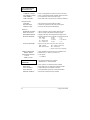
1
Bradyprinter THT Model
2024 and 2034
Thermal Transfer Printer
_______________________________________________________________________________
User’s Guide
LOGO
W.H. Brady Co.
Automatic Indentification Products
HP PCL-4, and HP Laser Jet II are Trademarks of Hewlett packard Corporation
CG Triumvirate is a trademark of Agfa Corporation.
CG Times, based upon Times New Roman under license from The Monotype
Corporation
plc, is a product of Agfa Corporation.
Futura is a registered trademark of Fundición Tipográfica Neufville, S.A.
Bradyprinter THT Model 2024 and 2034 is a Trademark of Brady USA Inc.
SEAQ PC and Batch are trademarks of Datamax Bar Code Products Corporation.
As an Energy Star Partner, Brady USA Inc. has determined that this product meets the
Energy Star guidelines for energy efficiency.
Information in this document is subject to change without notice and does not represent
a commitment on the part of Brady USA Inc. No part of this manual may be reproduced
or transmitted in any form or by any means, for any purpose other than the purchaser's
personal use, without the express written permission of Brady USA Inc.
© Copyright 1996 by Brady USA Inc.
6555 W. Good Hope Road • Milwaukee, WI 53223 • (414) 358-6600
All rights reserved. Printed in the United States of America.
Part Number: 88-2149-01
Revision: D
AGENCY COMPLIANCE AND APPROVALS:
UL:
CSA:
TUV:
UL1950 Information Technology Equipment
C22.2 No. 950-M93
EN60950, IEC950
1. Nur für Gebrauch innerhalb eines Gebäudes geeignet.
2. Bei Gefahr, Kabel aus der Steckdose herausziehen
3. Falls kein Kabel mitgeliefert wurde, bitte Folgendes bei der Anschaffung eines Kabels beachten:
Für 230 Volt (Europa): Benützen Sie ein Kabel, das mit "HAR" markiert ist, bestehend mindestens aus
einem H05VV-F Kabel, das mindestens 0,75 Quadratmillimeter Drahtdurchmesser hat; sowie eine
IEC320 Steckdose und einen für das Land geeigneten Stecker, 6A, 250 Volt.
1. This unit is intended for indoor use only.
2. Disconnect power supply cord in case of emergency.
3. When power supply cord is not provided; for proper power supply cord selection please see below:
For 230 Volt Operation (Europe): Use a cord set, marked "HAR," consisting of a min H05VV-F cord
which has a minimum 0.75 square mm diameter conductors, provided with an IEC 320 receptacle and a
male plug for the country of installation rated 6A, 250V
FCC:
This device complies with Part 15 of FCC rules.
Note: This equipment has been tested and found to comply with the limits for a Class A digital device,
pursuant to Part 15 of the FCC Rules. These limits are designed to provide reasonable protection against
harmful interference when the equipment is operated in a commercial environment. This equipment
generates, uses, and can radiate radio frequency energy, and if not installed and used in accordance with
the instructions in this manual, it may cause harmful interference to radio communications. Operation of
this equipment in a residential area is likely to cause harmful interference in which case the user will be
required to correct the interference at his own expense.
IMPORTANT SAFETY INSTRUCTIONS
Your Bar Code Printer has been designed to give you many years of safe,
reliable service. As with all electrical equipment, there are a few basic
precautions you should take to avoid getting hurt or damaging the Printer.
•
Carefully read the installation and operating instructions provided
with your Printer.
•
Read and follow all warning instruction labels on the Printer itself.
•
Place the Printer on a flat, firm, solid surface.
•
To protect your Printer from overheating, make sure all openings on
the Printer are not blocked.
•
Do not place the Printer on or near a heat source, (i.e., a radiator or
heat register).
•
Do not use your Printer near water, or spill liquid of any kind into it.
•
Be certain that your power source matches the rating listed on the back
of the Printer. If you are unsure, check with your dealer or with your
local power company.
•
As a safety device, your Printer has a grounded, 3-prong plug that will
only fit into a grounded outlet. If you cannot plug it in, chances are
you have an older, non-grounded outlet. Contact an electrician to have
the outlet replaced. Do not use an adapter to defeat the grounding.
•
Do not place the power cord where it will be walked on. If the power
cord becomes damaged or frayed replace it immediately.
•
Do not insert anything into the ventilation slots or openings on the
Printer.
•
Only qualified, trained service technicians should attempt to repair
your Printer.
♦
CONTENTS
♦ Introduction
1.0
1.1
1.2
1.3
Introduction .................................................................1
Technical Specifications..............................................3
Standard Ribbon Sizes................................................5
Label/Tag Specifications .............................................6
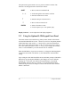
♦ Getting Started
2.0 Introduction .................................................................7
2.1 Unpacking...................................................................7
2.2 Checking the AC Power Requirements........................8
2.2.1 Selecting 230 VAC Operation...........................9
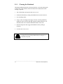
2.3 Connecting the Printer...............................................10
2.3.1
Interfacing to the Printer .................................11
2.3.2 Dip Switch Settings ........................................13
2.4 Memory Cartridges....................................................14
2.5 Media Loading ..........................................................15
2.5.1
Using the Optional Internal Rewind.................18
2.5.2 Using the Peel and Present Option.................20
2.6 Ribbon Installation and Removal...............................22
♦ Using Your Printer
3.0 Introduction ...............................................................25
3.1 Front Control Panel ...................................................25
3.1.1 Optional LCD/Keypad Front Panel..................27
3.2 Using the Optional LCD/Keypad Front Panel.............28
3.3 Self-Test ...................................................................33
3.3.1 Test Label Examples..........................................34
3.3.2
Configuration Test Label...................................36
3.3.3 Character Dump Mode..................................... 38
3.4 Factory Default Setup ...............................................39
3.5 Fuse Replacement ....................................................39
i
♦ Printing Labels
4.0
4.1
4.2
4.3
4.4
Introduction ...............................................................41
Programming Commands .........................................42
Programming Example .............................................48
Printing Bar Codes ....................................................48
Printing Lines and Boxes...........................................50
♦ Maintenance and Adjustments
5.0 Introduction ...............................................................51
5.1 Printer Maintenance Schedules.................................51
5.1.1 Cleaning the Printhead ...................................52
5.2 Troubleshooting ........................................................54
5.2.1 Optional LCD/Keypad Front Panel Alarms......56
5.3 Mechanical Adjustments ...........................................57
5.3.1
Media Width Adjustment ................................58
5.3.2
Media Sensor Adjustment...............................59
5.3.3
Printhead Replacement ..................................60
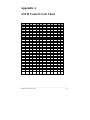
Appendix A
ASCII Control Code Chart ..................................................... A-1
Appendix B
Available Fonts and Bar Codes ............................................. B-1
B.1 Human-Readable Fonts .......................................... B-2
B.2 Bar Code Fonts ....................................................... B-5
Appendix C
C.1 Error Codes............................................................. C-1
Appendix D
D.1 Support Services..................................................... D-1
Appendix E
E.1 Warranty Information ............................................. E-1
ii
♦
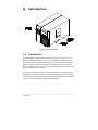
Introduction
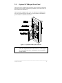
Figure 1-1 Overall View
1.0
Introduction
The Bradyprinter™ THT Model 2024 & 2034, hereafter referred to as 'the
Printer', is a high performance, low cost, direct thermal or thermal transfer
label printer that uses Reduced Instruction Set Computing (RISC) technology.
With its standard 203 DPI (Dots Per Inch) printhead, the Printer can print
labels at speeds of up to 10" per second. The thermal transfer model allows for
the use of thermal transfer ribbons.
An innovative dot history control circuit called SEAQ, (Sequential Energy
Adjustment for Quality), provides exceptional print quality by monitoring the
printhead data and automatically adjusting the printhead element temperatures
to provide maximum printhead quality and performance.
_______________________________________________________________________
Introduction
1
The Printer can be connected to almost any computer through its
RS-232C/RS422 serial interfaces, IEEE parallel option, or to an IBM
or IBM compatible mainframe through its optional twinax/coax interface.
The Printer can be equipped with operator and field-installed options such as a
Cutter, Peel and Present (requires factory installed Internal Rewind), On-line
Verification, DRAM, Internal Batch Cartridge, and Memory Cartridges. In
addition, the Printer can be purchased with factory installed options, (i.e.,
Internal Rewind, 300 DPI printhead, and LCD\Keypad front panel), that
expand the Printer's capabilities.
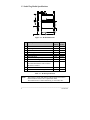
Figures 1-1 and 1-2 depict the Printer's parts placement.
Figure 1-2 Mechanism Detail
_______________________________________________________________________
2
Introduction
1.1
Technical Specifications
Print Technology:
Thermal Transfer − standard
Resolution:
203 DPI (8 dots/mm) − standard
Optional 300 DPI − factory installed
Print Speed:
203 DPI 2 to 10 IPS
300 DPI 2 to 8 IPS
Bar Code Modules:
5 mil to 110 mil "X" dimension in picket or ladder
orientations @ 203 DPI.
3.3 mil to 80 mil "X" dimension in picket or ladder
orientations @ 300 DPI.
Print Width:
4.1" (104mm) maximum
Media Width:
.75" (19mm) − 4.65" (118mm)
Label Length:
12" @ 203 DPI w/512KB (standard)
.25" minimum in batch mode
.75" minimum in tear off or peel mode
12" @ 300 DPI w/1MB (standard)
.25" minimum in batch mode
.75" minimum in tear off or peel mode
Media Type:
Roll-Fed, Die-Cut Continuous, Fan Fold, Tags or
Tickets
Media Thickness:
.0025 - 0.010" (.0635mm to .254mm), standard widths
(.0050 - .0080 for .75" −1" label widths)
Media Supply:
8" (203mm) maximum diameter on 3"(76mm) cores
Bar Codes:
Code 39, Interleaved 2 of 5, Code 128 (Subsets A, B,
and C) Codabar, UPC-A, UPC-E, UPC 2 and 5 digit
addendums, EAN-8, EAN-13, EAN 2 and 5 digit
addendums, Code 93, UPC random weight, Universal
Shipping Container Symbology Plessy, Postnet,
UCC/EAN 128, PDF 417 and Maxicode
Internal Fonts:
CG Triumvirate Bold/Condensed (scalable)
CG Triumvirate (smooth bit mapped font 6 - 48 pt)
_______________________________________________________________________
Introduction
3
Cartridge Slots:
One Cartridge Slot (Memory)
Standard DRAM:
512KB w/203DPI, 1 MB w/300DPI
Standard EPROM:
2048KB w/203 DPI, 2048KB w/300DPI
Counters:
2 Linear Inch Counters; one absolute and one
resettable
Interface:
RS232, RS422 @ 300 -19,200 baud, XON/XOFF,
CTS/RTS
Dimensions:
11.38" H x 10" W x 18.25" D (289mm H x 254mm W
x 463mm D)
Operating
Temperature:
40° F to 105° F (5° C to 40° C)
Power Source:
115 VAC or 230 VAC 60HZ/50HZ
Additional Options
LCD/Keypad:
Front panel with a 2 row x 16 character LCD display
and a 6 key operator's keypad
DRAM:
Expandable to 4MB (via a daughter board)
256KB/512KB
Flash Cartridge:
Permanent Storage of Custom Fonts, Graphics, and
Formats
Cutter with Tray:
Maximum Thickness: 0.010" (.254mm)
Internal Rewinder:
5½" maximum O.D. capacity with no core
Twinax/Coax:
Supports IBM Mid-range and Mainframe Computers
High Speed Interface: IEEE Parallel Interface plus Serial I/F up to 56K BPS
Present Sensor:
On-demand label dispensing
Internal Batch:
Cartridge with VT 100 emulation and storage
Cartridge with Link MCII emulation and storage
_______________________________________________________________________
4
Introduction
1.2 Standard Ribbon Sizes
The manufacturer stocks the following standard ribbon sizes: 1.57", 2.36",
3.27", and 4.33". The standard ribbon length is 328 linear yards. It is
recommended that the width of the thermal-transfer ribbon be within 10% of
the label width. Additional sizes other than those listed are available on a
custom-order basis.
_______________________________________________________________________
Introduction
5
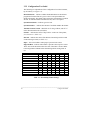
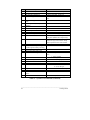
1.3 Label/Tag Media Specifications
Figure 1-3 Media Dimensions
Description
A
B
C
D
E
F
G
H
I
J
K
Label width
Backing width
Gap between labels
Label length
Backing thickness
Label thickness
Width of sensor opening
Distance media edge to sensor opening
Reflective sensor mark width. It is
recommended that the entire width of
the label is marked.
Distance between reflective mark
Reflective sensor mark length
MAX.
MIN.
(inches)
(inches)
4.650
4.650
99.99
99.99
0.010
0.010
0.500
2.250
4.00
0.750
0.750
0.100
0.250
0.0023
0.0025
0.200
0.200
1.000
99.99
99.99
0.500
0.100
Table 1-1 Media Specifications
NOTE:
The reflective sensor mark must be carbon based. The sensor is
infrared and will reflect off of a plain black mark.
The total thickness of label and backing is .010 inches max.
_______________________________________________________________________
6
Introduction
♦
Getting Started
2.0
Introduction
This chapter will assist you in unpacking, configuring the communications,
connecting your Printer, loading media stock, and installing the ribbon.
2.1
Unpacking
Inspect the shipping container(s) for signs of shipment damage. If damage is
evident, contact the carrier directly to specify the nature and extent of the
damage.
The printer is packed in molded styrofoam packaging. The Printer is enclosed
in a plastic bag to reduce the chance of moisture damage during shipment.
Remove the Printer from the plastic bag.
In addition to this manual, the shipping container(s) should include the
following standard items:
•
•
•
Label printer
AC power cord
Special or additional items purchased.
_______________________________________________________________________
Getting Started
7
2.2
Checking the AC Power Requirements
The standard Printer is configured for 115 VAC +10% single-phase 50/60 Hz
with a properly-grounded outlet. A small sticker next to the power cord
connection states the power requirements.
The Printer is also manufactured for 230 VAC operation, most of these Printers
are shipped to international markets. If you are uncertain as to the power
requirements of the Printer, or the outlet you are connecting to, check with a
qualified service technician to verify the installation before connecting AC
power.
Check the rear AC switch settings before applying power. The
facing arrows must by selected to match the supplied voltage
rating, (115VAC or 230VAC).
CAUTION
_______________________________________________________________________
8
Getting Started
2.2.1
Selecting 230 VAC Operation
If your Printer's AC power requirements do not match your AC power, the rear
AC voltage selection switch can be changed. If you wish to change from 115
VAC to 230 VAC, follow the instructions outlined below.
1.
Remove the AC power cord (if installed).
2.
Insert a flat bladed-screwdriver into the release slot and push out the fuse
holder/voltage selector switch.
3.
Flip/rotate the fuse holder/voltage selection switch over and re-insert it.
4.
Attach the 230V power cord.
Figure 2-1 Selecting 230 VAC
_______________________________________________________________________
Getting Started
9
2.3
Connecting the Printer
You will need a serial cable to connect your computer to the Printer's
RS232/RS422 serial interface connector. Connect your Printer's cables as
outlined below.
1.
Make sure both the Printer and host computer are turned off.
2.
Plug the serial cable connector securely into the Printer's serial connector
and then attach it to the connector.
3.
Plug the other end of the cable into the computer's serial interface.
NOTE:
An optional parallel port is available. See your retailer for details.
Figure 2-2 Rear Printer Connections
_______________________________________________________________________
10
Getting Started
2.3.1
Interfacing to the Printer
For most applications, the interface between the Printer and the host device will
be RS-232C. The interface cable is connected between the Printer and the host
via the DB-25 connector. The DB-25 connector is labeled "serial" and is
located on the back of the Printer. Several typical cable interfaces are listed in
Table 2-1.
The Printer supports both XON/XOFF and CTS/DTR handshaking. For
connection to most host systems, the XON/XOFF handshaking works to reduce
the number of wires needed in the interface cable. For interfacing RS-422
devices, the XON/XOFF handshake is the only appropriate method. Refer to
Table 2-2 for the appropriate communications cable needed for your
configuration.
_______________________________________________________________________
Getting Started
11
When a serial (RS-232C) interface between the Printer and the host will be
used, a serial interface cable is needed to connect the Printer to the host. Cable
configurations for typical interfaces are shown below, (contact your reseller for
part numbers and ordering information).
Null Modem (MXM)
“PC” (DB25P) to Printer
“PC” (DB9P) to Printer
RS-422 Connection
Table 2-1 Interface Cable Applications
Other applications may require a parallel connection from the Printer to the
host. The Printer can be connected to the host with a standard parallel printer
cable if the Printer is equipped with the optional parallel interface option.
_______________________________________________________________________
12
Getting Started
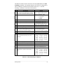
2.3.2
Dip Switch Settings
For proper operation, you must set the baud rate, parity,
and stop bits of the Printer's interface. On the rear of the
Printer, you will find SWITCH 1 (S1), an eight-position
dip switch used to set the Printer's communications
parameters, (see Table 2-3).
NOTE: SWITCH 1 (S1) is not available with the LCD/Keypad Front Panel
Option, (see Section 3.2 when setting the communications parameters
for this option).
Baud Rate
9600
4800
2400
1200
600
300
19200
TEST/9600
Word length/Parity
7-Bit /Even
8-Bit /None
Compatibility Mode
(Form Edge Offset)
Offset =1.10" (27.9mm)
Offset =2.20" (55.9mm)
Present Sensor
Enable
Disable
Control Codes
Standard
Alternate
Cutter Enable
Disable
Enable
S1-1
S1-2
S1-3
S1-4
S1-5
S1-6
S1-7
S1-8
OFF
OFF
OFF
OFF
ON
ON
ON
ON
OFF
OFF
ON
ON
OFF
OFF
ON
ON
OFF
ON
OFF
ON
OFF
ON
OFF
ON
X
X
X
X
X
X
X
X
X
X
X
X
X
X
X
X
X
X
X
X
X
X
X
X
X
X
X
X
X
X
X
X
X
X
X
X
X
X
X
X
X
X
X
X
X
X
ON
OFF
X
X
X
X
X
X
X
X
X
X
X
X
X
X
X
X
OFF
ON
X
X
X
X
X
X
X
X
X
X
X
X
X
X
X
X
ON
OFF
X
X
X
X
X
X
X
X
X
X
X
X
X
X
X
X
OFF
ON
X
X
X
X
X
X
X
X
X
X
X
X
X
X
X
X
OFF
ON
Table 2-2 Communications Dip Switch Settings
NOTE:
Select the 8-bit word length if you wish to access the foreign
language characters from the ASCII Code chart. These characters
are available in fonts 1–6 and 9.
_______________________________________________________________________
Getting Started
13
2.4
Memory Cartridges
The Printer has one standard memory cartridge slot. The primary use of the
memory cartridges is for storing label formats, graphic images, fonts and for
internal batch. Follow the instructions outlined below when installing memory
cartridges.
1.
Ensure that all printing has been completed.
2.
Open the Side Access Cover.
3.
Plug the Memory Cartridge into the Memory Cartridge Slot with the label
face-up.
Figure 2-3 Installation of a Memory Cartridge
NOTE: Use only memory cartridges designed specifically for your Printer,
flash modules have a Write Protect Switch.
_______________________________________________________________________
14
Getting Started
2.5
Media Loading
The Printer supports up to an 8" (203mm) diameter roll of media, (if media less
than 4 inches wide is used, refer to Section 5.3.1 before loading media). Follow
the instructions outlined below when installing the media stock.
1.
Open the Printer's Side Access Cover.
2.
Rotate the Printhead Latch (1) counterclockwise to unlatch and raise the
Printhead to an upright position.
3.
Lower the Hinge Plate (2).
4.
Slide the Media Edge Guide (3) to the outer edge and rotate it to the down
position.
Figure 2-4 Media Access
_______________________________________________________________________
Getting Started
15
NOTE:
5.
If using fanfold media, skip steps 5 and 6. Install fanfold media as
shown in figure 2-5b.
Place the 3" Media Core Adapters on the Media Hub Assembly, (if using
media with 3" media cores).
Figure 2-5a Media Installation (3" core)
6.
Place the Media Supply Roll on the Media Hub Assembly. Slide the media
retainer against the supply roll and tighten the thumb screw.
NOTE:
Do not use the media retainer if the Media Supply Roll is wider than
4 inches (102mm).
_______________________________________________________________________
16
Getting Started
7.
Route the media over the Guide Plate, between the Media Sensor, and over
the Platen Roller, (located beneath the Printhead), as shown in Figure 2-5b.
8.
Rotate the Media Edge Guide up and slide it to the media's edge.
9.
Close the Hinge Plate and lower the Printhead by rotating the Printhead
Latch clockwise to the latched position.
Figure 2-5b Media Installation
NOTE: If the media is not sensing, try adjusting the Media Edge Sensor by
turning the Media Edge Sensor Adjustment knob (see Section
5.3.2).
_______________________________________________________________________
Getting Started
17
2.5.1
Using the Optional Internal Rewind
If the Internal Rewind Option is installed in your Printer, then the media and
Arc Plate should be installed as described below.
NOTE: The Arc Plate is supplied only with the Internal Rewind Option.
1.
Turn off the Printer and open the Side Access Cover.
2.
Follow steps 2, 3, and 4 of Section 2.5 before installing media.
3.
Open the Lower Right Front Panel.
4.
Remove the Arc Plate from its stored position and install it on the front of
the Printer as shown in Figure 2-6.
Figure 2-6 Installing the Arc Plate for Internal rewind
5.
Place the media core adapters on the Media Hub Assembly if using 3"
cores, (see Figure 2-5a).
_______________________________________________________________________
18
Getting Started
6.
Place the Media Supply Roll on the Media Hub Assembly. Slide the media
retainer against the Media Supply Roll and tighten the thumb screw.
NOTE:
Do not use the media retainer if the media is wider than 4" (102
mm).
7.
Route the media over the Guide Plate, between the Media Sensor, and over
the Platen Roller, (located beneath the Printhead), around the Arc Plate
and to the Media Rewinder as shown Figure 2-7.
8.
Place the Clasp over the end of the media and rotate the Media Rewinder a
few turns.
9.
Rotate the Media Edge Guide up and slide it to the media's edge.
10. Close the Hinge Plate and latch the Printhead by rotating the Printhead
Latch upward to the latched position. Close the side cover.
Figure 2-7 Installing Media with Internal Rewind Option
_______________________________________________________________________
Getting Started
19
2.5.2
Using the Peel and Present Option
The Peel and Present Option allows for on-demand label dispensing and
requires the Internal Rewind Option. To use this option follow the instructions
outlined below.
1.
Turn off the Printer and open the Side Access Cover.
2.
Follow steps 2, 3, and 4 of Section 2.5 before installing media.
3.
Open the Lower Front Panel.
4.
Using a phillips screw driver, remove the Tear Bar, invert it (flip it over),
and re-install it as shown in Figure 2-8.
Figure 2-8 Using the Peel and Present Option
NOTE: If media narrower than 4 inches is used, refer to Section 5.3.1 before
loading media.
_______________________________________________________________________
20
Getting Started
5.
Place the Media Supply Roll on the Media Hub Assembly. Slide the media
retainer against the supply roll and tighten the thumb screw.
6.
Route the media over the Guide Plate, between the Media Sensor, and over
the Platen Roller (located beneath the Printhead).
7.
Route the media liner (backing) around the Tear Bar to the Media
Rewinder as shown in Figure 2-9.
8.
Place the Clasp over the end of the media and rotate the Media Rewinder a
few turns.
9.
Rotate the Media Edge Guide up and slide it to the media's edge.
10. Lift and snap the Lower Right Front Panel closed.
11. Close the Hinge Plate and latch the Printhead by rotating the Printhead
Latch clockwise to the latched position. Close the side cover.
Figure 2-9 Installing Media using Peel and Present Option
_______________________________________________________________________
Getting Started
21
2.6
Ribbon Installation and Removal
Follow the instructions below when installing the thermal transfer ribbon.
Ribbon Installation:
1.
Open the Side Access Cover.
2.
Rotate the Printhead latch counterclockwise to unlatch and raise the
Printhead.
3.
Lower the Hinge Plate.
4.
Place the new Ribbon Supply Roll on the Supply Hub, making sure that the
ribbon roll is pushed up against the hub flange.
Figure 2-10 Ribbon Installation
_______________________________________________________________________
22
Getting Started
5.
Route the ribbon as shown in Figure 2-10 to the Take-Up Hub.
6.
While holding the ribbon Take-Up Hub, rotate the J-hook clockwise to
unlatch it.
7.
Raise the J-hook upward and place the end of the ribbon over the Take-Up
Hub.
Figure 2-11 Ribbon Installation showing J-hook
8.
Slide the J-hook back into place as shown in Figure 2-11. While holding
the ribbon Take-Up Hub, rotate the J-hook counter-clockwise to latch.
9.
Turn the Take-Up Hub until all of the ribbon slack is removed.
_______________________________________________________________________
Getting Started
23
10. Raise the Hinge Plate and close the Printhead by rotating the Printhead
Latch clockwise.
11. Locate the Ribbon ON/OFF switch, (see Figure 2-12), and slide the switch
to the right to select Thermal Transfer (ribbon on). This Switch is not
available with the LCD/Keypad Front Panel Option, (see Section 3.2).
Figure 2-12 Selecting Ribbon On (Thermal Transfer)
Ribbon Removal:
1.
Cut the ribbon anywhere between the Take-Up Hub and Printhead.
2.
Rotate the Printhead Latch counterclockwise to raise the Printhead, then
lower the hinge plate.
3.
While holding the ribbon Take-Up Hub, rotate the J-hook clockwise to
unlatch it, then slide off the used ribbon.
4.
Turn the Ribbon Supply Hub clockwise to draw the unused portion of the
ribbon back onto the Ribbon Supply Roll.
5.
Raise the Hinge Plate and close the Printhead by rotating the Printhead
Latch clockwise.
_______________________________________________________________________
24
Getting Started
♦
Using Your Printer
3.0
Introduction
This chapter will explain the front panel operation, how to install memory
cartridges, and replace the fuse.
3.1
Front Control Panel
The Printer has five (5) operator accessible switches and three (3) LED
indicators, (see Figure 3-1). A brief description of the switches and LED
indicators is listed in this section.
Figure 3-1 Front Panel
The POWER indicator light is lit when power is
available and the rear POWER switch is activated.
_______________________________________________________________________
Using Your Printer
25
This indicator is lit when no media edge and/or no
ribbon motion is detected; a fault condition.
The PAUSE indicator will turn on if any of the
following occurs:
• The PAUSE switch is pressed.
• A print job is canceled with the CANCEL switch.
This switch temporarily interrupts the printing
process illuminating the Pause LED. A second press
allows printing to resume and extinguishes the LED.
When pressed the paper will advance to the first
print position of the next label. In addition this
button is used to clear fault conditions indicated by
the Ribbon Media LED.
Interrupts and deletes the active print job.
RIBBON ON/OFF
SWITCH:
For direct thermal printing, (no ribbon), slide the
switch to the "off " position. For thermal transfer
printing, (ribbon installed), slide the switch to the
"on" position. This Switch is not present on the
LCD/Keypad Front Panel Option.
DARKNESS POT:
This potentiometer is used to fine adjust print
darkness to variations in the media. This
potentiometer is not present on the LCD/Keypad
Front Panel Option.
_______________________________________________________________________
26
Using Your Printer
3.1.1
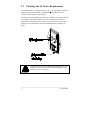
Optional LCD/Keypad Front Panel
The Printer can be equipped with an optional, factory-installed LCD/Keypad
front panel. If this option is installed on your Printer, refer to this section for
menu and function information.
The front panel is equipped with a 2 row x 16 character LCD display and a
(six) 6 key operator's keypad. The three (3) control switches and indicators
operate the same as indicated in Section 3.1.
Figure 3-2 Optional LCD/Keypad Front Panel
NOTE:
If the Printer was purchased with the optional LCD/Keypad front
panel, the configuration for the Printer will be set via the keypad.
On the standard Printer, these configurations are set through the
rear dip switches.
_______________________________________________________________________
Using Your Printer
27
The operator's keypad consists of six (6) pressure sensitive switches. The
function of each keypad switch is described as follows:
SHIFT
• Moves to the next available field
ï ð
• Scrolls through the current menu selection
• Increases and decreases values
ñ
• Returns to the previous menu level
ò
• Moves to the next menu level
ENTER
• Selects a function or value
• Used to respond "yes" to an operator query
Display Contrast − used to adjust the LCD display brightness
3.2
Using the Optional LCD/Keypad Front Panel
The menu structure is divided into two primary menus, BASIC FUNCTION
and ADVANCED SETUP. Use the ò arrow key to move to the primary BASIC
FUNCTION menu, then use the ï ð arrow keys to scroll to the desired sub
menu. Once in the desired sub menu, use the òñ arrow keys to move into or
out of the desired sub menu. Use the ï ð arrow keys to display the available
values. Use the ENTER key to set the desired value or condition.
When the ENTER key is pressed, an asterisk (*) will appear indicating that the
selection has been made. The asterisk (*) also indicates the current default
setting.
Upon exiting the ADVANCED SETUP menu, the Printer prompts 'CHANGES
DEFAULT'. By pressing the ENTER key the changes are saved as defaults.
Pressing the ñ arrow key exits without saving the changes, except under
DATE/TIME, and areas where no asterisk (*) is used for default. Exiting
without saving will cause all changes to return to the default values when the
Printer is turned off.
_______________________________________________________________________
28
Using Your Printer
Basic Function
BASIC FUNCTION
PRINT METHOD
DIRECT*
TRANSFER
BASIC FUNCTION
SELECT TOF
GAP*
REFLECTIVE
CONTINUOUS
• Selects the type of printing desired
• Selects direct thermal printing (no ribbon installed)
• Selects thermal transfer printing (ribbon installed)
• Top Of Form
• Default − looks for gap between labels
• Senses black stripe on back side on media
• No Top Of Form sensing
BASIC FUNCTION
DARKNESS
• Used to balance a new Printhead's level of darkness
Values 1-64
• 1 indicates the lightest and 64 indicates darkest setting
BASIC FUNCTION
COMM SETUP
• Sets the parameters for the communication port
*PORTA 9600
8 N 1 BOTH
BASIC FUNCTION
LABEL PRESET
ENABLE
DISABLE*
BASIC FUNCTION
CUTTER
ENABLE
DISABLE*
BASIC FUNCTION
RIBBON SAVER
ENABLE
DISABLE*
• Communications port and Baud rate, Word length,
Parity, Stop Bits, Protocol.
Word lengths = 7, 8
Parity
= None, Even, Odd
Stop Bits
= 1, 2
Protocols
= BOTH, DTR, XON/XOFF
Baud rates
= 300, 600, 1200, 2400, 4800, 9600,
19200
• Selects the Peel and Present Option
• Selects the Present Sensor
• No Present Sensor selected
• Controls Cutter Option, if installed
• Cutter Option installed or selected
• No Cutter Option installed or used
• Controls Ribbon Saver Option, if installed
• Ribbon Saver selected (stops ribbon from advancing
during voids of .95 inches or larger)
• Ribbon Saver not installed or selected
* represents default settings
_______________________________________________________________________
Using Your Printer
29
BASIC FUNCTION
INTERNAL BATCH
• Allows internal label creation with Internal Batch
Cartridge
ENABLE
DISABLE*
BASIC FUNCTION
CONVERSION
METRIC
DECIMAL*
BASIC FUNCTION
TOF ADJUST
• Used to set the Printer's system of measurement
• Printer interprets all measurements as metric values
• Printer interprets all measurements as decimal values
• Selects the point where the label's edge is detected by
the sensor
• Set start of print from the label's edge. 128 sets the
start
of print approximately .3 inches, (7.6 mm) from the
label's edge
Advanced Setup
ADVANCED SETUP
COUNTERS
ABSOLUTE VALS.
RESETTABLE VALS.
RESET COUNTERS
ADVANCED SETUP
DATE/TIME
• Non-resettable counter (viewed only)
• User resettable counter (can keep track of labels)
• Resettable values re-start at 0
• Allows current date and time to be set
SET DAY NAME day
hh:mm a dd mon yr
ADVANCED SETUP
LABEL OPTIONS
HEAT SETTING
PRINT SPEED
SLEW SPEED
BACKFEED SPEED
ROW ADJUST
COLUMN ADJUST
CONT. LABEL LEN
• Values: 00 to 30, (*10) (0 = lightest, 30 =darkest)
• Values: 2ips to 10ips, (*6) (Print speed/ inches per
sec)
• Values: 2ips to 10ips, (*7) (Label feed rate/ inches
per
sec.
• Values: 2ips to 5ips, (*3.5), (rate the printer backs up
label
• Vertical position where printing begins, (*0) (shifts
up)
• Values 0 to 410, (0*)
• Values 0000 to 9999, (*0) (00.00 to 99.99")
(label page length)
* represents default setting
_______________________________________________________________________
30
Using Your Printer
LABEL WIDTH
PRESENT DIST.
• Values 75 to 410 (.75 to 4.1"), label printing width
in inches (*410)
• Distance from the printhead to where the label stops
(*0)
ADVANCED SETUP
SYSTEM OPTIONS
FACTORY SETTING
SECURITY CHECK
• Returns the Printer to its original factory settings
• Selects security features to protect Advanced Setup
PASSWORD
DIP SWITCH #1
NONE*
MODIFY PASSWORD
INTERNAL MODULE
0 - 1000
SCALABLE FONT
0 - 1000
SYMBOL SET
28 SELECTIONS
• Allows the user to change the entry password
• Internal Module (ID-A). Memory size- 4K byte blocks;
default 15
• Scalable font cache allocation 4K byte blocks (*0)
• Scalable font symbol set selection, see Programmer's
Manual
ADVANCED SETUP
OPERATION
PAUSE MODE
ENABLE
DISABLE*
FEEDBACK MODE
ENABLE
DISABLE*
TEST MODE
ENABLE
DISABLE*
• Suspends printing between each label until the pause
button is pressed
• Returns ASCII character 30 after each label and
character 31 after each batch of labels are printed
• Sends debug characters to host while printing
ADVANCED SETUP
COMMUNICATIONS
SERIAL PORT A
CONTROL CODES
• Standard and alternate control codes
* represents default setting
_______________________________________________________________________
Using Your Printer
31
ADVANCED SETUP
MAINTENANCE
TEST PRINT
CURRENT CONFIG
DATABASE CONFIG
TEST RIBBON
TEST PATTERN
FRONT PANEL
LED TEST
KEYPAD TEST
DISPLAY TEST
TEST I/O
MONITOR GP INPUT
TEST GP OUTPUT
SENSOR READINGS
DIGITAL SENSORS
•
•
•
•
Prints a configuration test label of current selections
Prints a configuration label of default menu selections
Test reflects the status of the ribbon type
Prints label with a test pattern (to check dot elements)
• Exercises the front panel indicator LEDs
• Checks the operation of the front panel keypad
• Exercises the front panel LED display
•
•
•
•
Allows monitoring of the General Purpose Input
Allows testing of the General Purpose Output
Displays the status of the digital and analog sensors
Displays digital sensors with active values below them
HD = Head
CT = cutter
LP = label present
RS = ribbon saver
ANALOG SENSORS
SERIAL LOOPBACK
SERIAL PORTA
INSTALLED OPTION
CUTTER
RIBBON SAVER
ADVANCED SETUP
MODULES
PRINT DIRECTORY
PRINT FILE
COPY MODULE
TEST MODULE
FORMAT MODULE
D=Down
D=Down
Y=Blocked
D=Down
U=Up
U=Up
N= Not Blocked
U=Up
• Displays 4 analog sensors with sensor values below each
THR = Thermal
RF* = reflective TOF mode
RIB = Ribbon motion TR* = Transmissive
(* only the active mode is displayed)
• Serial loopback connector must be installed for test
• Initiates test (see Self-Test, Section 3.3.)
• Lists options
* = installed
• The optional modules are available
Module Slot A − External Flash
•
•
•
•
•
Prints contents of selected memory modules
Prints label, font, or image from selected module
Copies data from one module to another
Tests Read/Write operation of selected modules
Formats the selected memory modules
_______________________________________________________________________
32
Using Your Printer
3.3
Self-Test
Power On Self-Test
If the Printer's power switch is off, begin the Self-Test by using the Power-On
method. With the Printer OFF, load the media (at least 4 inches wide) to be
used and ribbon, (if equipped and/or desired), optionally install one of the SelfTest Plugs. Press and hold the FEED button and turn the Printer ON. Release
the Feed switch after the Ribbon/Media LED indicator flashes once. The
Printer will then print the two test labels and operation will continue in the
Character Dump Mode.
Figure 3-3 Self-Test Plugs
NOTE:
After performing a Power-Up and Self-Test the Printer will be in
'Character Dump Mode'. Turn the Printer OFF
momentarily, then back ON to restore normal operation.
_______________________________________________________________________
Using Your Printer
33
The Self-Test may also be initiated while the power is on by simultaneously
pressing the PAUSE and CANCEL buttons. Simultaneously release them and
immediately press and hold the FEED button until the ribbon/media LED
flashes.
NOTE:
If any configuration errors are indicated by the Self-Tests, check the
Printer's dip switch settings or configuration setup.
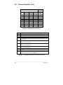
3.3.1 Test Label Examples
The first test label printed will be the Configuration Label, this label lists the
Printer's configuration and status. The following sample was produced on a
standard printer without the test plugs installed.
FRI
VER:
SEPTEMBER 23,
ROM
CHECKSUMS
GA
1996 10:12 340
1.14
01/30/96
-
U13
U24
47-2091-01P
47-2090-01P
U34
47-2088-01B
U2
47-2089-01B
SYSTEM RAM CHECKS_ _ _ _ GOOD SYSTEM RAM SIZE_ _ 512 KBYTES
SERIAL
PORT
SWITCH 1
INTERNAL
BAUD
1
ON
1
OFF
RATE IS 9600
2
ON
2
OFF
3
ON
3
OFF
4
OFF
4
OFF
TRANSFER SWITCH IS ON
5
OFF
5
OFF
6
7
8
OFF OFF OFF
6
OFF
INPUT VALUES
PAPER: 255
POT : 120
EDGE:
TOFA:
253
120
REFL:
RIBN:
0 TEMP:
10 RWND:
76
0
COUNTER INFORMATION
ABSOLUTE VALUES 2-21-1996
LENGTH_ _ _ _
2317 INCHES
__
1 HOURS
RESETABLE VALUES 9- 5-1995
LENGTH_ _ _ _
2317
TIME_ _ _ _ _ _
1 HOURS
MEMORY CONFIGURATION
INTERNAL MODULE_ _ _ _ _ _ _ _ 15
SCALABLE FONTS_ _ _ _ _ _ _ _
TIME_ _ _ _
0
Figure 3-4 Configuration Test Label
_______________________________________________________________________
34
Using Your Printer
The second of the two test labels is the Test Pattern Label. This label is used
to determine whether the Printhead is in need of replacement. 'Good' and
'Bad" test pattern labels are shown in Figure 3-5.
Good test label indicates
Printhead is operating normally.
Streaks in test label indicate a
dirty or faulty Printhead.
(See Chapter 3 for cleaning and
replacement).
Figure 3-5 Printhead Test Label
_______________________________________________________________________
Using Your Printer
35
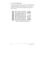
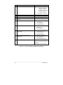
3.3.2 Configuration Test Label
The following are explanations of the Configuration Test Label elements,
top to bottom, (see Figure 3-5).
Rom Checksums − indicates whether the ROMs that store the Printer's
program and resident fonts are 'good' or 'bad'. Good part numbers are
displayed normally. Checksum values replace the part numbers to indicate
an error. If either the ROM or RAM test is bad, service is required.
System Ram Checks − indicates 'good' or 'bad'.
System Ram Size − indicates the amount of available RAM in the Printer.
Thermal Transfer Switch − Should be 'on' if using a ribbon, and 'off ' if
in the direct-thermal mode (no ribbon).
Switch 1 − indicates the status of dip switch 1 on the rear of the printer,
(see Section 2.3.2, Table 2-3).
Internal − indicates the status of the Printer's internal dip switch located
on the main logic board (see Table 3-1).
Paper − this value indicates when paper is present in the sensor.
Edge and Refl − indicates when media is present at the respective sensor.
These sensors tell the Printer where the start of the label is located. Refer
to the Programmer's Manual when determining which sensing mode to
use.
Switch Functions
RS-422 Disabled
RS-422 Address 1
RS-422 Address 2
RS-422 Address 3
RS-422 Address 4
RS-422 Address 5
RS-422 Address 6
RS-422 Address 7
Spare
Resettable Counter Reset
Spare
RS-422 Termination (hw)
1
OFF
ON
OFF
ON
OFF
ON
OFF
ON
X
X
X
X
2
OFF
OFF
ON
ON
OFF
OFF
ON
ON
X
X
X
X
3
OFF
OFF
OFF
OFF
ON
ON
ON
ON
X
X
X
X
4
X
X
X
X
X
X
X
X
OFF
X
X
X
5
X
X
X
X
X
X
X
X
X
OFF
X
X
6
X
X
X
X
X
X
X
X
X
X
OFF
X
7
X
X
X
X
X
X
X
X
X
X
X
OFF
Table 3-1 Internal Dip Switch Settings
_______________________________________________________________________
36
Using Your Printer
Temp − this reading is the feedback voltage of the printhead thermistor. At
power up or in an idle condition, this value should be in the range of 060 to
065. A reading of 175 is high and could
decrease the life of the printhead. An average amount of printing will give
readings that range from 070 to 120.
Pot − this reading comes from the darkness potentiometer located on the
front panel board. It will vary from 000 (darkest) to 255 (lightest). Adjust
this value for a midrange value of 128.
TOFA − (Top of Form Adjustment) determines where the first position of
print begins on the label.
RIBN − this value indicates the operation of the ribbon mechanism, this
value will vary.
RWND − this value indicates the operation of the internal rewind
mechanism, this value will vary.
Counter Information − is the values and dates of the absolute and
resettable counters.
Memory Configuration − lists the current size of the 'Internal Module'
RAM in 4K byte blocks, and the 'Scalable Fonts' current cache setup for
scalable font calculations.
_______________________________________________________________________
Using Your Printer
37
3.3.3 Character Dump Mode
After printing the configuration test labels, the Printer will automatically enter
the Character Dump Mode. This mode allows the user to input strings of data
and compare them with the output data from the Printer. This label can
readily uncover a buffer overflow problem identified by large gaps of data in
the character string.
Figure 3-5 ASCII Character Dump Label
_______________________________________________________________________
38
Using Your Printer
3.4 Factory Default Setup
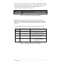
With the Printer OFF, press and hold the FEED, CANCEL, and PAUSE
buttons while turning the Printer ON. Continue to hold the buttons until the
Ribbon Media LED illuminates a second time. The Printer will now be set to
the 'Factory Defaults'.
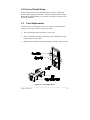
3.5
Fuse Replacement
The Printer uses a 2.0 amp/250V slo-blo fuse, which is located within the
voltage selection switch, just below the power switch.
•
Turn off the Printer and remove the AC power cord.
•
Insert a flat-bladed screwdriver in the release slot and push out the fuse
holder/voltage selector switch.
•
Replace the fuse with the same type and rating, (250volts, 2Amp, slo-blo).
Figure 3-6 Fuse Replacement
_______________________________________________________________________
Using Your Printer
39
_______________________________________________________________________
40
Using Your Printer
♦
Printing Labels
4.0
Introduction
This chapter explains how to generate labels using several different methods,
and how to print different bar codes. An optional Internal Batch Cartridge is
available for generating label formats using the Printer as a stand-alone device.
A VT 100 or LINK MCII compatible CRT is required if the optional Internal
Batch Cartridge is used to generate labels. The Internal Batch Cartridge
Program works much like a PC compatible software package, but uses internal
batch modules instead of a hard or floppy disk drive to store and retrieve label
formats.
Labels can also be generated using RS-232 to a host computer or by using a PC
with a compatible labeling software package. This chapter explains some of the
basic programming commands that are required when writing programs to
generate label formats.
NOTE: The programming information contained in this manual is for
reference purposes only. Refer to the Programmer's Manual for
detailed descriptions and programming formats.
_____________________________________________________________________________________________________
Printing Labels
41
4.1
Programming Commands
To prompt the Printer for a command sequence, the Printer must first receive a
special character called an “attention getter”, which informs the Printer that it
is about to receive a command and the type of command it will be. Immediate
Commands, System Level Commands, and Font Loading Commands each have
their own attention getter. The attention getter character is followed by a
"command character" that tells the Printer what action to take.
ASCII
Char.
SOH
STX
ESC
Decimal
Value
1
2
27
HEX
Value
01
02
1B
DOS
Attention Getter For
Prompt
Ctrl A Immediate Commands
Ctrl B System Level Commands
Crtl [ Bitmapped Font Loading Commands
Table 4-1 Attention Getters
When the Printer receives an "immediate" command it will stop whatever it is
doing and perform that command. Commands of all types must be in the
following sequence:
1.
2.
3.
Attention Getter
Command Character
Command Parameters, (if any).
Command
Character
Printer
Responds?
#
A
B
C
D
E
F
Y
Y
N
N
N
Y
Y
Command
Reset
Send ASCII Status String to Host
Toggle Pause
Cancel
SOH Shutdown
Send Batch Quantity
Send Status Byte
Table 4-2 Immediate Commands
_____________________________________________________________________________________________________
42
Printing Labels
The System Level Commands are used to create formats, load and store graphic
information, and control the Printer. Table 4-3 provides a brief description and
format of each System Level Command character.
Char
Description
A
Set time and date
a
Enable feedback characters
B
c
d
Get Printer time and date information
Set continuous paper length
E
e
F
f
Set quantity for stored label
Select edge sensor
Form feed
Set form stop position (BACKFEED)
G
I
Distance to peel off or present
position
Print last label format
Input graphics data block
See the Programmer's Manual for
format
i
J
K
Download scalable font
Set pause for each label
Extended System Commands
Set Printer to double buffer mode
Refer to the Programmer's Manual for
proper format
n = M,S, or W for set memory config.
<STX>KMxxxx:Syyyy:Wzzzz
Format
FORMAT: AwmmddyyyyhhMMjjj
16 digits total
= 1 digit week, 1 is Monday
w
= 2 digits for month
mm
= 2 digits for day
dd
= 4 digits for year
yyyy
= 2 digits for hour (24 hr ft)
hh
= 2 digits for minutes
MM
= 3 digits for Julian I.D. value
jjj
Returns decimal 30 after each label and
31 after each batch of labels
Print time and date to port
nnnn= length of paper to feed per label
Use to print a label while a second is
formatting in memory
Ennnn = Set quantity for stored label
For "see through" media sensing, etc.
Feeds one label at a time
fnnn
nnn = 3 digits from sensor
A bank designation, an optional word
length modifier, a format designation,
and up to a 16-character string to
identify the stored image data
Kn
n = Q - for query
M - Set configuration
S - Scalable font cache
W - Label width
R - Reset memory config.
f - Set form stop position
<STX>Kfxxxx defines distance between
the Printhead and stop position
Table 4-3 System Level Commands
_____________________________________________________________________________________________________
Printing Labels
43
Char
k
L
M
m
n
Description
Test RS-232 Port With a Y if OK
Enter label formatting mode
Set maximum label length
Set metric flag, enter metric mode
Format
Sends character "Y" to RS-232 port
4 digits (nnnn) Max. 99.99 inch.
All measurements set to metric until
reset
o
P
p
Q
q
R
Clear metric flag, return to inch
mode
Form edge offset (start of print
position)
Cycle cutter
Enter character dump mode
Controlled pause
Clear all memory modules
Clear module "q(A/B)"
Ribbon Saver
r
Select reflective sensor
S
s
Feed rate
Set for 1 dot buffer processing. Used
for full length dot buffer processing
Printhead dot pattern test label
Label format field replacement
Software switch settings
Vn n = 4 -label present, 2 -Internal
batch
1 -Cutter enabled
Firmware version information
Sends version string to Host
Request memory module Information Wa
a = F -font, G -graphic, L -label
Test FLASH module memory
Takes about 90 seconds
Set default module bank
Xa
a = Memory Module ID, A or B
Delete module file
xMFname M = A/B module ID,
F = F,G,L file type
Output sensor values
Sends sensor values status to RS-232 port
Symbol set select
ySaa aa = Symbol set ID, see B-1
Print internal information and dot
pattern
Pack module
Za a = Memory Module ID, upper case
O
T
U
V
v
W
w
X
x
Y
y
Z
z
Onnnn nnnn = in/100 or mm/10
qa a = Module ID, upper case
Rx x = (Y/N) default = Dip switch or
front panel (Ribbon Saver Option only)
Used for "black-strip" media sensing, i.e.
continuous tags, butt-cut labels. Stripe
must be printed on back side of media
Sr
r = C - W, 2.0 - 12.0 ips.
Table 4-3 System Level Commands (Continued)
_____________________________________________________________________________________________________
44
Printing Labels
The STX L command switches the Printer from the system level to the label
formatting command. All command characters after STX L are interpreted as
Label Formatting Commands until terminated with E,X, or s. All label
formatting commands are terminated with 0D HEX.
CC
Description
:
Set cut by amount (4 digits)
The cutter function will perform a cutting
action after the number of labels specified
A Set format attribute
C
c
D
Set column offset amount
Set cut by amount (2 digits)
Set height and width dot size
E
G
H
Terminate field generation and print label
Place data in global register
Enter heat setting
(The amount of heat applied per dot row can
be used to help control print quality)
Mirror text/bar code
Set metric mode
Print speed
Enter maximum speed for print cycle, 1
character
Format
:nnnn
nnnn = 4 digits of labels printed
before cut. Default = 0001
An n = 1 - XOR
2 - Transparent
3 - Opaque
5 - Inverse
Cnnnn nnnn = Inches/100
cnn nn = 2 cut amount
h = Horiz. dot size; can be 1 or 2
v = Vert. dot size; can be 1,2, or 3
(0.005" steps) Default is “D22”
M
m
P
p
Q
R
r
Set label backup speed
Enter quantity of labels to print
Set row offset amount
Recall stored label format
S
Slew speed
Sets maximum speed for label feeding. 1
digit.
Hnn nn = 2 digits. 1 - 30
10 is nominal and default
Print contrast is relative to speed
Second transmission restores print
Pa
C
D
E
F
G
H
a = single
2.0 ips
2.5 ips
3.0 ips
3.5 ips
4.0 ips
4.5 ips
char.
I 5.0 ips
J 5.5 ips
K 6.0 ips
L 6.5 ips
M 7.0 ips
N 7.5 ips
O 8.0 ips
P 8.5 ips
Q 9.0 ips
R 9.5 ips
S 10.0 ips
pa
a = single char. (C - I)
Qnnnn nnnn = quantity
Rnnnn nnnn = row offset
rnn...n nn...n label name of up
to 16 char. terminated by CR
Sa a = single character
C
D
E
F
G
H
2.0 ips
2.5 ips
3.0 ips
3.5 ips
4.0 ips
4.5 ips
I 5.0 ips
J 5.5 ips
K 6.0 ips
L 6.5 ips
M 7.0 ips
N 7.5 ips
O 8.0 ips
P 8.5 ips
Q 9.0 ips
R 9.5 ips
S 10.0 ips
Table 4-4 Label Formatting Commands
_____________________________________________________________________________________________________
Printing Labels
45
CC
Description
s
Store label format in module
T
U
X
Z
z
+
Set field data line terminator
Make previous field a string replace field
Terminate label formatting node
Zero (0) conversion to "O" to eliminate
slash (/)
Make last field entered increment numeric
-
Make last field entered decrement numeric
>
Make last field entered increment
alphanumeric
<
Make last field entered decrement
alphanumeric
^
Set count by amount
Format
sann...n a - destination module
A Memory Module A
B Memory Module B
C Default memory bank
D Memory module D
E Memory module E
nn...n - label name (16 char. max)
Tnn - nn = 00-FF, 2 digit ASCII
+pii Make last entered field
incrementing
p = Zero fill character
ii = Data added to field
-pii Make last entered field
decrementing
p = Zero fill character
ii = Data subtracted from field
>pii Make last entered field
incrementing. 0 - Z
p = Zero fill character
ii = Data added to field
<pii Make last entered field
decrementing. 0 - Z
p = Zero fill character
ii = Data subtracted from field
^nn Specifies the number of
labels printed before field data is
updated
nn = 2 digits, number of labels
Table 4-4 Label Formatting Commands (Continued)
_____________________________________________________________________________________________________
46
Printing Labels
There are two special commands used by the Printer, the STX S (Recall Global
Data) and the STX T (Print Date and Time) commands. Unlike the other Label
Format Commands, which follow the STX L command, these special
commands are entered directly into the data field.
Character
<STX>S
<STX>T
Description
Recall global data and place in field.
Print time and date.
Table 4-5 Special Label Formatting Commands
Bitmapped font loading commands are usually generated by font creation
software. However, the assigned font ID number command must be sent to the
Printer before the font file. Refer to Table 4-6 for the font loading command
characters.
The downloaded font will be stored in the "default" module, (see STX X).
Command
Character
Description
*c###D
Assign Font ID Number
)s###W
*c###E
(s#W
Format
<ESC>*c###D
### = font ID Number 100 to 999
Font Descripton
<ESC>)s#W
# = Bytes of Font Descriptor Data
Character Code
<ESC>*c###E
# = ASCII Value of Character
Character Download Data <ESC>(s###Wnn...n
#
= Bytes of Bit-mapped Data
nn..n = Bit mapped data
Table 4-6 Bitmapped Font Loading Commands
_____________________________________________________________________________________________________
Printing Labels
47
4.2
Programming Example
The following ASCII text file will generate the label shown in Figure 4-1.
<STX>L<CR>
H07<CR>
D11<CR>
19110080100002510K OHM 1/4 WATT<CR>
1a6210000000050590PCS<CR>
E
10K OHM 1/4 WATT
Figure 4-1 Sample Label
4.3
Printing Bar Codes
The example shown below prints out a Code 3 of 9 bar code with a wide to
narrow bar ratio of 3:1, and can be used to print any of the bar codes shown in
Appendix B by altering the examples fields. Refer to Figures 4-2 and 4-3 for a
brief explanation of the data fields.
<STX>L<CR>
D11<CR>
1A93040001501000123456789<CR>
121100000000100Barcode A<CR>
E
_____________________________________________________________________________________________________
48
Printing Labels
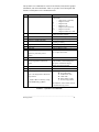
Field
DESCRIPTION
Rotation
1 = 0 deg. • 2 = 90 deg. • 3 = 180 deg. • 4 = 270 deg.
Bar Code/Font
ID
Any valid font character or bar code type. Bar codes automatically
select bar code field format. Bar code types designated by uppercase
ALPHA letters print with human-readable interpretations. Lowercase
ALPHA bar code fonts print as bars only. Font designated by 0 - 9.
Represents the number of times the dot tables are multiplied for the
selected font or the specific width for Bar Codes. .005 increments.
They both accept 1-9 and A-K. For UPC and 128 fonts, only 1,2,3,4,6,
& 8 are valid when interpretation is printed.
Must be 3 digits. 001-999 (in/100 or mm/10)
Must be 4 digits. 0000-9999 (in/100 or mm/10)
Must be 4 digits. 0000-0410 (in/100 or mm/10)
ASCII printable data for font/bar code selected. Terminate with a
<CR>.
Width
multiplier
Height
Row
Column
Data string
Figure 4-2 Example line 3
Figure 4-3 Example line 4
_____________________________________________________________________________________________________
Printing Labels
49
4.4
Printing Lines and Boxes
Lines and boxes can be created by requesting font “X”. The horizontal and
vertical multipliers, and row/column position work with the line and box
routines in the same manner as human-readable fonts. The format of the data
area is as follows:
LINES:
Lhhhvvv
L = “L” specifies line drawing
hhh = horizontal width of line
vvv = vertical height of line
LINES:
lhhhhvvvv
1 = “1” specifies line drawing
hhhh = horizontal width of line
vvvv = vertical height of line
BOXES:
Bhhhvvvbbbsss
B = “B” specifies box drawing
hhh = horizontal width of box
vvv = vertical height of box
bbb = thickness of bottom and top box edges
sss = thickness of sides of box
BOXES:
bhhhhvvvvbbbbssss
b = “b” specifies box drawing
hhhh = horizontal width of box
vvvv = vertical height of box
bbbb = thickness of bottom and top box edges
ssss = thickness of sides of box
_____________________________________________________________________________________________________
50
Printing Labels
♦
Maintenance and Adjustments
5.0
Introduction
This chapter contains information about maintaining your Printer,
troubleshooting tips, solutions, and Printer adjustment information.
5.1
Printer Maintenance schedules
If your Printer is equipped with an optional Rotary Cutter, it is recommended
that the cutter's blades are cleaned every 25,000 cuts. The blades in the Rotary
Cutter, although reversible, can not be sharpened and must be replaced if they
become dull.
The Media Path and Printhead should be cleaned each time a new roll of media
is installed in the Printer.
The Tear Bar can become gummed up from the media backing. The Tear Bar
should be cleaned with Isopropyl Alcohol when build-up is noticeable.
_____________________________________________________________________________________________________
Maintenance and Adjustments
51
5.1.1
Cleaning the Printhead
The thermal printhead should be cleaned periodically, or when the print quality
is affected by a dirty printhead. Follow the instructions outlined below when
cleaning is required.
1.
Turn off the Printer and open the Side Access Cover.
2.
Unlatch the Printhead by rotating the Printhead Latch counter-clockwise.
3.
Lower the Hinge Plate.
4.
Using a cotton swab dipped in Isopropyl Alcohol, clean the printhead by
rubbing the cotton swab left and right along the Printhead Element. Care
should be taken not to scratch the Printhead with the cotton swab.
5.
Raise the Hinge Plate and engage the Printhead Latch by rotating it
clockwise.
6.
Close the Side Access Cover.
Allow the printhead surface to cool 2 − 3 minutes before
cleaning. Do not touch the printhead with your fingers or
lubricant of any kind.
CAUTION
_____________________________________________________________________________________________________
52
Maintenance and Adjustments
Figure 5-1 Cleaning the Printhead
_____________________________________________________________________________________________________
Maintenance and Adjustments
53
5.2
Troubleshooting
This section identifies some causes and solutions to specific problems that may
effect the Printer.
1) The Printer prints strange characters or garbage instead of the label:
Possible cause and solution:
•
The Printer is in the dump mode, perform a reset by pressing and
releasing the PAUSE and CANCEL switches simultaneously, or by
turning the Printer off and back on again.
•
The Printer is set up for 8 data bits but the host PC is set up for 7 data
bits, see Section 2.3.2, (or 3.2 if equipped with optional LCD/Keypad
front panel) for instructions.
2) The Printer does not print:
Possible cause and solution:
•
The media is incorrectly loaded , (see Section 2.5).
•
The Printhead is incorrectly latched, (see Section 2.5).
•
If the Direct Thermal Mode is selected, make sure that direct thermal
media is installed, (see Section 3.1 or 3.2).
•
The Media Sensor is incorrectly adjusted, re-adjust the sensor, (see
Section 5.3.2).
•
The Media Sensor may be bad, return the Printer for service.
_____________________________________________________________________________________________________
54
Maintenance and Adjustments
3) The media slips or does not properly advance:
Possible cause and solution:
•
The Head Level Adjustment Knob setting is adjusted too high,
adjust the Head Level Adjustment Knob, (see Section 5.3.1).
•
The Platen Roller is dirty, clean the Platen Roller.
re-
4) Uneven printing or print too light:
Possible cause and solution:
•
The Hinge Plate is open or unlatched, re-latch the hinge plate, (see
Section 5.1, steps 6, 7, and 8).
•
The Head Level Adjustment Knob setting is adjusted too high, readjust the head level adjustment knob, (see Section 5.3.1).
•
The darkness is adjusted too low, readjust.
5) Poor print quality:
Possible cause and solution:
•
The Printhead is dirty, clean the printhead, (see Section 5.1).
•
The wrong ribbon/paper combination is being used, use a different
type of ribbon and/or paper.
•
The Printhead temperature is too high or too low. Use software control
to adjust the heat settings or darkness via the optional LCD/Keypad
Front Panel.
•
The Printhead is bad, ( see Section 5.3.3).
6) No display − power light is on (LCD/Keypad front panel):
Possible cause and solution:
•
Display contrast set too low, turn the contrast adjustment clockwise
until the display appears.
•
The LCD display is defective, return the Printer for service.
_____________________________________________________________________________________________________
Maintenance and Adjustments
55
5.2.1
Optional LCD/Keypad Front Panel Alarms
If the Printer is equipped with the Optional LCD/Keypad Front Panel, it has
built in monitors for the Printer status and stock conditions. The alarm
messages will be displayed on the front panel LCD display indicating the
present status of the Printer, stock levels, or whether the Printer’s electronics
have detected an error condition.
LCD Display
Alarm Description
PROM FAULT
Power up initialization detected a PROM failure,
call for service.
RAM FAULT
Power up initialization detected a RAM failure,
call for service.
RTC RAM FAULT
The RTC Non Volatile RAM failed its checksum
test, call for service.
PRINT HEAD FAULT
The Thermal Printhead Control Circuit failed, call
for service.
ADC FAULT
The Analog to digital converter failed, call for
service.
The Printer failed to find the top of form position.
Possible causes:
• Defective stock
• Maximum Label Length, (set from
communications or front panel), is smaller than
one form.
The Printer is out of stock.
TOF FAULT
OUT OF STOCK
RIBBON FAULT
The ribbon system detected a fault
Possible causes:
• Out of ribbon
• Ribbon motion was prohibited
• Obstructions in the paper movement may cause
ribbon faults.
_____________________________________________________________________________________________________
56
Maintenance and Adjustments
LCD Display
Alarm Description
CUTTER FAULT
The cutter operation failed
Possible causes:
• Cutter not installed
• Jam in cutter
• Defective cutter hardware, call for service.
Warning:
Turn OFF the Printer and remove the AC power
cord before attempting to remove any jam or
obstruction from the cutter.
RIB SAVER FAULT
The Ribbon Saver operation failed
Possible causes:
• Obstruction in ribbon area
• Ribbon Saver Option is not installed
• Defective ribbon saver hardware, call for
service.
CUTTER NotEQP
The Cutter Option is enabled and the cutter is not
present
RIBSVR NotEQP
The Ribbon Saver Option is enabled and the
ribbon saver is not present
5.3
Mechanical Adjustments
The following mechanical adjustments should be performed only when
required, additional sections that follow provide detailed descriptions for each
adjustment.
•
Media Width adjustment, (see Section 5.3.1).
•
Media sensor adjustment, (see Section 5.3.2).
•
Printhead Replacement, (see Section 5.3.3).
_____________________________________________________________________________________________________
Maintenance and Adjustments
57
5.3.1
Media Width Adjustment
This adjustment allows the use of narrower media, (less than 4 inches wide) in
the Printer.
1.
Rotate the Head Level Adjustment Knob clockwise to raise the minimum
printhead to platen position for narrow media.
NOTE:
Rotate the head level adjustment knob counterclockwise to lower the
minimum printhead to position.
2.
Install the media, (see Section 2.5).
3.
Print a Self-Test Label, (see Section 3.3).
Figure 5-2 Media Width Adjustment
4.
If the print quality is unacceptable, repeat steps 1 and 3 until the print
quality is acceptable.
_____________________________________________________________________________________________________
58
Maintenance and Adjustments
5.3.2
Media Sensor Adjustment
To detect the media's edge for different media widths, the Media Sensor can be
adjusted across half the media path. The Media Sensor may require adjustment
when changing to a media of a different width. The gauge behind and below
the printhead can be viewed for making this adjustment
1.
Open the Side Access Cover.
2.
Make sure that the media guide is moved to the edge of the media.
3.
Rotate the Media Sensor Adjustment knob clockwise to adjust for narrower
media and counterclockwise for standard width media.
NOTE: Do not force or over tighten the Media Sensor Adjustment Knob.
Figure 5-3 Media Sensor Adjustment
_____________________________________________________________________________________________________
Maintenance and Adjustments
59
5.3.3
Printhead Replacement
The Printhead is operator replaceable and can be replaced with a flat- bladed
screw driver. If dot patterns on the Configuration Test Label indicate lines of
missing dots, (as shown in Figure 5-4), the printhead is dirty or may require
replacement.
Figure 5-4 Configuration Test Label
A single missing dot, or two non-adjacent dots, does not indicate a bad
printhead; however, multiple adjacent missing dots do indicate a bad printhead.
Removal:
Follow the procedure below when replacing the printhead,
Figure 5-5).
(see
1.
Turn off the Printer and open the Side Access Cover.
2.
Rotate the Printhead Latch downward to unlatch the Printhead, then raise
the Printhead to an upright position and lower the Hinge Plate.
_____________________________________________________________________________________________________
60
Maintenance and Adjustments
3.
Using a flat-bladed screw driver, loosen the Thumb Screw and lower the
Printhead from the Printhead Mounting Plate.
4.
Using the screw driver, push against the Printhead connector's guide to
free the connector from its socket, then remove the Printhead.
Replacement:
5.
Push the new Printhead into the connector. Align the Printhead with the
alignment pins, (located on the bottom of the Printhead Mounting Plate),
and secure with the Thumb Screw, (do not over tighten).
6.
The Printhead must be cleaned if touched by any fingers or oils, (see
Section 5.1.1).
7.
Lower the Printhead, raise the Hinge Plate, and rotate the Printhead Latch
until it is closed.
Figure 5-5 Printhead Removal
_____________________________________________________________________________________________________
Maintenance and Adjustments
61
_____________________________________________________________________________________________________
62
Maintenance and Adjustments
Appendix A
ASCII Control Code Chart
Char
NUL
SOH
STX
EXT
EOT
ENQ
ACK
BEL
BS
HT
LF
VT
FF
CR
SO
SI
DLE
DC1
DC2
DC3
DC4
NAK
SYN
ETB
CAN
EM
SUB
ESC
FS
GS
RS
US
Dec
0
1
2
3
4
5
6
7
8
9
10
11
12
13
14
15
16
17
18
19
20
21
22
23
24
25
26
27
28
29
30
31
Hex
00
01
02
03
04
05
06
07
08
09
0A
0B
0C
0D
0E
0F
10
11
12
13
14
15
16
17
18
19
1A
1B
1C
1D
1E
1F
Char
!
"
#
$
%
&
›
(
)
*
+
,
.
/
0
1
2
3
4
5
6
7
8
9
:
;
<
=
>
?
Dec
32
33
34
35
36
37
38
39
40
41
42
43
44
45
46
47
48
49
50
51
52
53
54
55
56
57
58
59
60
61
62
63
Hex
20
21
22
23
24
25
26
27
28
29
2A
2B
2C
2D
2E
2F
30
31
32
33
34
35
36
37
38
39
3A
3B
3C
3D
3E
3F
Char
@
A
B
C
D
E
F
G
H
I
J
K
L
M
N
O
P
Q
R
S
T
U
V
W
X
Y
Z
[
\
]
^
_
Dec
64
65
66
67
68
69
70
71
72
73
74
75
76
77
78
79
80
81
82
83
84
85
86
87
88
89
90
91
92
93
94
95
Hex
40
41
42
43
44
45
46
47
48
49
4A
4B
4C
4D
4E
4F
50
51
52
53
54
55
56
57
58
59
5A
5B
5C
5D
5E
5F
Char
`
a
b
c
d
e
f
g
h
i
j
k
l
m
n
o
p
q
r
s
t
u
v
w
x
y
z
{
|
}
~
Dec
96
97
98
99
100
101
102
103
104
105
106
107
108
109
110
111
112
113
114
115
116
117
118
119
120
121
122
123
124
125
126
127
Hex
60
61
62
63
64
65
66
67
68
69
6A
6B
6C
6D
6E
6F
70
71
72
73
74
75
76
77
78
79
7A
7B
7C
7D
7E
7F
_____________________________________________________________________________________________________
ASCII Control Code Chart
A-1
Char
Dec
Hex
Char
Dec
Hex
Dec
Hex
Char
Dec
Hex
Ç
128
80
á
160
A0
Char
192
C0
Ó
224
E0
ü
129
81
í
161
A1
193
C1
ß
225
E1
é
130
82
ó
162
A2
194
C2
Ô
226
E2
â
131
83
ú
163
A3
195
C3
Ò
227
E3
ä
132
84
ñ
164
A4
196
C4
õ
228
E4
à
133
85
Ñ
165
A5
197
C5
Õ
229
E5
å
134
86
ª
166
A6
ã
198
C6
µ
230
E6
ç
135
87
°
167
A7
Ã
199
C7
þ
231
E7
ê
136
88
¿
168
A8
200
C8
Þ
232
E8
ë
137
89
®
169
A9
201
C9
Ú
233
E9
è
138
8A
170
AA
202
CA
Û
234
EA
ï
139
8B
1/2
171
AB
203
CB
Ù
235
EB
î
140
8C
1/4
172
AC
204
CC
ý
236
EC
ì
141
8D
¡
173
AD
205
CD
Ý
237
ED
Ä
142
8E
174
AE
206
CE
238
EE
Å
143
8F
175
AF
207
CF
239
EF
É
144
90
176
B0
ð
208
D0
240
F0
æ
145
91
177
B1
Ð
209
D1
241
F1
Æ
146
92
178
B2
Ê
210
D2
242
F2
ô
147
93
179
B3
Ë
211
D3
243
F3
ö
148
94
180
B4
È
212
D4
244
F4
ò
149
95
Á
181
B5
|
213
D5
245
F5
û
150
96
Â
182
B6
Í
214
D6
÷
246
F6
ù
151
97
À
183
B7
Î
215
D7
¸
247
F7
ÿ
152
98
©
184
B8
Ï
216
D8
º
248
F8
Ö
153
99
¹
185
B9
217
D9
¨
249
F9
Ü
154
9A
186
BA
218
DA
·
250
FA
ø
155
9B
187
BB
219
DB
251
FB
£
156
9C
188
BC
220
DC
252
FC
Ø
157
9D
¢
189
BD
221
DD
253
FD
x
158
9E
¥
190
BE
222
DE
254
FE
ƒ
159
9F
191
BF
223
DF
255
FF
Ì
±
3/4
The printable characters shown are from the font 9, internal Triumvirate,
character set.
NOTE:
For the hardware handshake XON/XOFF commands
XON = (DC1)
XOFF = (DC3)
_____________________________________________________________________________________________________
A-2
ASCII Control Code Chart
Appendix B
Available Fonts and Bar Codes
All character fonts and bar codes available with the Printer are described in this
section. Each font and bar code has a name associated with it for use in
programming. Human-readable fonts have numeric names while bar code fonts
have alpha names. Uppercase alpha names will print bar codes with humanreadable interpretations, while lowercase alpha names will print bar codes only.
Fonts 0 through 8 use the slash zero (Ø) conventions for distinguishing
between the zero and the letter O. The slash can be removed with the label
formatting command Z. These fonts are non-proportional (monospaced) fonts,
all of the characters take up the same amount of space when printed. This is
helpful when using variable data in a fixed area. The sizes of these fonts are
shown in Table B-1.
The Triumvirate font number 9 is a proportional font, each character will take
up a different amount of space when printed. For example, the letter W will be
larger than the letter I.
There are 29 scalable font symbol sets that are accessible:
(US) ISO 6: ASCII Symbol Set, font code S00
(DN) ISO 60 Danish / Norwegian Symbol Set, font code S00
(IT) ISO 15: Italian Symbol Set, font code S00
(GR) ISO 21: German Symbol Set, font code S00
(FR) ISO 69: French Symbol Set, font code S00
(E5) ISO 8859/5 Latin 5 Set, font code S00
(E2) ISO 8859/2 Latin 2 Set, font code S00
(E1) ISO 8859/1 Latin 1 Symbol Set, font code S00
(DT) DeskTop Symbol Set, font code S00
For a complete list of the scalable fonts symbol sets, ASCII codes, and charts,
please refer to the Programmer's Manual.
_____________________________________________________________________________________________________
Appendix B
B-1
B.1 Human-Readable Fonts
Font Matrix Sizes
Font
0
1
2
3
4
5
6
7
8
Dot
Height
7
13
18
27
36
52
64
32
28
Dot
Width
5
7
10
14
18
18
32
15
15
Dot
Spacing
1
2
2
2
3
3
4
5
5
Charac.
Per Inch
203
DPI
33.83
22.56
16.92
12.69
9.67
9.67
5.64
10.15
10.15
Table B-1 Human-Readable Font Sizes
Font
0
1
2
3
4
5
6
7
8
9
Valid ASCII Characters, Decimal
32-126
32-168, 171, 172, 225
32-168, 171, 172, 225
32, 35-38, 40-58, 65-90, 128, 142-144, 146, 153, 154, 156, 157,
165, 168, 225
32, 35-38, 40-58, 65-90, 128, 142-144, 146, 153, 154,
156, 157, 165, 168, 225
32, 35-38, 40-58, 65-90, 128, 142-144, 146, 153, 154,
156, 157, 165, 168, 225
32, 35-38, 40-58, 65-90, 128, 142-144, 146, 153, 154,
156, 157, 165, 168, 225
32-126
32, 48-57, 60, 62, 67, 69, 78, 83, 84, 88, 90
32-126, 128-169, 171-173, 181-184, 189, 190, 198, 199, 208216, 222, 224-237, 241, 243, 246-250
Table B-2 Valid Human-Readable Font ASCII Characters
_____________________________________________________________________________________________________
B-2
Appendix B
0 - Identifies a 96-character
alphanumeric font.
1 - Identifies a 145-character
uppercase and lowercase
alphanumeric font that includes
descenders and ascenders.
2 - Identifies a 138-character
alphanumeric upper and
lowercase font.
3 - Identifies a 62-character
alphanumeric uppercase font.
4 - Identifies a 62-character alphanumeric uppercase font.
5 - Identifies a 62-character alphanumeric upper case font.
_____________________________________________________________________________________________________
Appendix B
B-3
6 - Identifies a 62-character
alphanumeric uppercase font.
7 - Identifies a font that prints OCRA, size I.
8 - Identifies a font that prints OCRB, size III.
9 - Identifies the internal Triumvirate font.
_____________________________________________________________________________________________________
B-4
Appendix B
B.2 Bar Code Fonts
Font
A
B
C
D
E
F
G
H
I
J
K
L
M
N
O
p
Q
R
S
T
u
v
z
Bar Code
3 of 9
UPC-A
UPC-E
Interleaved 2 of 5
Code 128
(A,B,C)
EAN-13
EAN-8
Health Industry
Bar Code (HIBC)
Codabar
Interleaved 2 of 5
without Bars
MSI Plessey
Interleaved 2 of 5
(UPC CASE)
UPC 2 digit add.
UPC 5 digit add.
Code 93
Postnet
UCC/EAN Code
128
UCC/EAN Code
128 K-MART
NON EDI
UCC/EAN Code
128 Random
Weight
Telepen
UPS MaxiCode
FIM
PDF-417
Length
Varies
11 digits
6 digits
Varies
Varies
Cksum
No
Yes
Yes
No
M-103
Valid Characters
0-9, A-Z, -. *$/+% and space char.
0-9
0-9
0-9
entire 128 ASCII character set.
12 digits
7 digits
Varies
Yes
Yes
M-43
Varies
(Min. 3)
Varies
No
0-9
0-9
0-9, A-Z, -$:/. The Host must
supply leading "+"'s
0-9, -, ., $, :, /, +, and the start/stop
codes: a, b, c, and d.
0-9
Varies
M-10
13
M-10
0-9. If + is last character,
additional MSI checksum will be
added to the bar code in place of
the + character.
0-9
2 digits
5 digits
Varies
Varies
19 digits
Yes
Yes
No
Yes
Yes
0-9
0-9
All 128 ASCII characters
0-9
0-9
18 digits
Yes
0-9
Varies.
At least
34 digits
Varies
84
1 char.
Varies
Yes
0-9
Yes
Yes
No
Yes
All 128 ASCII characters
0-9, A-Z
A, B, C, or D
All ASCII characters
M-10
Table B-3 Valid Bar Code Font ASCII Characters
_____________________________________________________________________________________________________
Appendix B
B-5
_____________________________________________________________________________________________________
B-6
Appendix B
Barcode O
_____________________________________________________________________________________________________
Appendix B
B-7
Barcode S
Barcode T
Barcode z
_____________________________________________________________________________________________________
B-8
Appendix B
Appendix C
Error Codes
The most common error codes transmitted by the Printer are described below.
Lower case “c”
Printer received a data byte from the host that contains a
framing error (corrupted) due to noise.
Lower case "e"
Memory module won't clear. Retry after a <STX> W
command.
Lower case “v”
Input buffer overflow.
Upper case “I”
This means that an invalid command sequence was sent
to the Printer. The Printer did not understand the
command sequence and terminated the command
interpreter.
Upper case “R”
This code will be sent every time the Printer is turned on,
this means there was a hardware reset.
Upper case “T”
This means that the Printer has had a watchdog time-out
condition. This is how a software reset occurs. A software
reset is made by sending the command sequence to the
Printer or by doing a front panel reset.
BELL HEX “07”
This is usually returned on a corrupt image download, or
if you try to load an image that is already installed in the
module.
_______________________________________________________________________
Appendix C
C-1
_______________________________________________________________________
C-2
Appendix C
♦ Appendix D
Support Services
How to reach us
For questions relating to the mechanical operation of Brady equipment you
already own, contact the Brady Technical Solution Center at 1-800-6438766, (fax) 414-358-6767, or by E-mail at [email protected].
Technical Support
Sometime during the life of your Brady equipment you may find yourself in
need of technical assistance. We provide fully-trained specialist to answer
any questions that you may have.
Technical Support Service via Telephone
Before you call: Misunderstanding instructions or omitting a step are the
most common sources of error. Please consult the manual and use the
Table of Contents and Appendixes for help.
Be Prepared: Only with ALL of the information requested can we give you
accurate and fast assistance. Also, you should be able to answer the
following questions when you call:
• Does the Printer perform all the Self-Test functions
properly?
• Does the Printer work properly with some equipment
but not with others?
• Are the cables the same? Were the configuration settings
changed?
• Is the problem limited to one label, or does it occur on
all of the labels.
The Technical Solution Center is available Monday − Friday,
7:00 a.m. to 7:00 p.m. CST, at 1-800-643-8766.
For technical support service in Europe, please call your local Brady
agency or distributor. You can also contact the Brady Technical Center in
Belgium at 32/ (0)52/45.79.94.
Technical Support via E-Mail or Fax
If you prefer to seek assistance in writing, please E-mail or fax a detailed
description of your problem to the E-Mail address or fax number shown
below. We recommend using the included customer service form that is on
page E-2. Enclose any sample printouts that might illustrate the problem.
FAX:
(414) 358-6767 or E-Mail: [email protected]
_______________________________________________________________________
Appendix D
D-1
W.H. Brady Company
Customer Service Form
Complete this form before requesting technical assistance.
Serial Number: _____________________________________________
Model Number: _____________________________________________
(Be specific, include ALL letters and numbers)
Company: _________________________________________________
Address: ___________________________________________________
City: _____________________________________________________
State, Zip: _________________________________________________
Phone: (____)_______________________________________________
Contact: ___________________________________________________
Hours available for return call: _________________________________
Hardware interface type: ______________________________________
Unit interfaced with: _________________________________________
Description of problem, including actions taken just prior to problem
occurring:
__________________________________________________________
__________________________________________________________
__________________________________________________________
__________________________________________________________
__________________________________________________________
__________________________________________________________
_______________________________________________________________________
D-2
Appendix D
Product Service and Support Programs
At Brady, our service and support goal is to keep your printer
performing optimally. Our service department provides a broad range
of service options and are your expert sources for your support and
maintenance needs. If you find yourself in need of technical assistance
or repair service, our Technical Solutions Center stands ready with
answers to any questions you may have.
_______________________________________________________________________
Appendix D
D-3
_______________________________________________________________________
D-4
Appendix D
Appendix E
Warranty Information
Brady
Limited Warranty Statement
Bradyprinter THT Model
Printer
Brady warrants to Purchaser that under normal use and service, the
Bradyprinter THT Model, (with the exception of the thermal printhead)
purchased hereunder shall be free from defects in material and workmanship
for a period of (365) days from the date of shipment by Brady.
Expendable and/or consumable items or parts such as lamps, fuses, labels and
ribbons are not covered under this warranty. This warranty does not cover
equipment or parts which have been misused, altered, neglected, handled
carelessly, or used for purposes other than those for which they were
manufactured. This warranty also does not cover loss, damages resulting from
accident, or damages resulting from unauthorized service.
Thermal Printhead
This warranty is limited to a period of ninety (90) days, or 1,000,000 linear
inches of use, whichever comes first, for the Bradyprinter THT Model. This
ninety (90) day warranty is valid only if a Brady-approved thermal or thermal
transfer label media is used, as defined in the then current Brady list of
Approved Thermal/Thermal Transfer Media, a copy of which is available from
Brady. Failure to use Brady-approved media is justification for invalidation of
this thermal printhead warranty. This warranty does not cover Printheads
which have been misused, altered, neglected, handled carelessly, or damaged
due to improper cleaning or unauthorized repairs.
_______________________________________________________________________
Appendix E
E-1
Warranty Service Procedures
If a defect should occur during the warranty period, the defective unit shall be
returned, freight and insurance prepaid, in the original shipping containers, to
Brady at: 6555 Good Hope Road, Milwaukee, WI 53223. An RMA (Return
Material Authorization) number must be issued before the product can be
returned. To open an RMA please call Brady's customer service department at
1-800-537-8791. Please include your RMA number on the outside of the box
and on the shipping document. Include a contact name, action desired, a
detailed description of the problem(s), and examples when possible with the
defective unit. Brady shall not be responsible for any loss or damages incurred
in shipping. Any warranty work to be performed by Brady shall be subject to
Brady's confirmation that such product meets Brady's warranty. In the event of
a defect covered by its warranty, Brady will return the repaired or replaced
product to the Purchaser at Brady's cost.
With respect to a defect in hardware covered by the warranty, the warranty
shall continue in effect until the end of the original warranty period, or for sixty
(60) days after the repair or replacement, whichever is later.
General Warranty Provisions
Brady makes no warranty as to the design, capability, capacity or suitability of
any of its hardware, supplies, or software.
SOFTWARE IS LICENSED ON AN 'AS IS' BASIS WITHOUT WARRANTY.
EXCEPT AND TO THE EXTENT EXPRESSLY PROVIDED HEREIN, AND
IN LIEU OF ALL OTHER WARRANTIES, THERE ARE NO
WARRANTIES, EXPRESSED OR IMPLIED, INCLUDING, BUT NOT
LIMITED TO ANY WARRANTIES OF MERCHANTABILITY OR FITNESS
FOR A PARTICULAR PURPOSE.
Purchaser shall be solely responsible for the selection, use, efficiency and
suitability of Brady's products.
_______________________________________________________________________
E-2
Appendix E
Limitation of Liability
IN NO EVENT SHALL BRADY BE LIABLE FOR ANY INDIRECT,
SPECIAL, OR CONSEQUENTIAL DAMAGES OR LOST PROFITS
ARISING OUT OF OR RELATING TO BRADY'S PRODUCTS, OR THE
PERFORMANCE OR NONPERFORMANCE THEREOF, EVEN IF BRADY
HAS BEEN ADVISED OF THE POSSIBILITY THEREOF. BRADY's
LIABILITY, IF ANY, TO ITS PURCHASER OR TO ANY CUSTOMER(S)
OF ITS PURCHASER SHALL IN NO EVENT EXCEED THE TOTAL
AMOUNT PAID TO BRADY BY THE INITIAL PURCHASER OF THE
DEFECTIVE PRODUCT.
IN THE EVENT ANY IMPLIED WARRANTIES (INCLUDING, BUT NOT
LIMITED TO, THE IMPLIED WARRANTIES OF MERCHANTABILITY
AND FITNESS FOR A PARTICULAR PURPOSE) ARE FOUND TO EXIST,
SUCH WARRANTIES ARE LIMITED IN DURATION TO THE PERIOD OF
THE WARRANTIES SET FORTH ABOVE.
Some States do not permit the exclusion of incidental or consequential
damages, and in those States the foregoing limitations may not apply. The
warranties here give you specific legal rights, and you may have other legal
rights which vary from State to State.
_______________________________________________________________________
Appendix E
E-3
_______________________________________________________________________
E-4
Appendix E