1
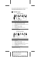
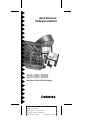
Quick Reference:
Hardware Installation
AHA-3980/3980W
AHA-3985/3985W
MultiChannel PCI-to-SCSI RAID Adapters
R
AA
AAAA
AA
AAAAAAAA
AAAAAAAA
AAAAAAAA
AAAAAAAA
AAAAAAAA
AAAAAAAA
AAAAAAAA
AAAAAAAA
AAAAAAAA
AAAAAAAA
AAAAAAAA
AAAAAAAA
AAAAAA
AA
AA
AHA-3980/3980W/3985/3985W Quick Reference: AA
AA
AA
AA
AA
Hardware Installation
AA
AA
AA
AA
AA
AA
Part
Number:
510673-00,
Rev.
D
AA
AA
AA
AA
AA
AA
Print Spec Number: 492990-00
AA
AA
AA
AA
AA
AA
Current
Date:
10/3/95
ECN
Date:
10/10/95
AA
AA
AA
AA
AAAAAAAAAAAAAAAAAAAAAAAAAAAAAAAAAAAAAAAAAAAAAAAAAAAAAAA
AA
This guide explains how to install the AHA®-398x
RAID adapters: the AHA-3980, AHA-3980W,
AHA-3985, and AHA-3985W. The guide contains the
information most users need to quickly install the
RAID adapters. If you have never installed SCSI devices,
you may prefer to use the detailed installation instructions in AHA-3980/3980W/3985/3985W User’s Guide.
1 READ THIS FIRST!
Before you continue, make sure your system meets
the following minimum requirements. If it does not,
the AHA-398x will not work!
■
The motherboard chipset and system BIOS must
support
– PCI-to-PCI bridges
– A 64-KByte BIOS
– Multiple interrupts
– at least one full length PCI slot
To determine whether your motherboard provides this support, contact your vendor, or call
Adaptec’s Interactive Fax system for a list of compatible motherboards (the number is on page 12).
■
The computer must comply with PCI Rev. 2.0.
■
If you are running NetWare 3.11, the clib.nlm must
be version 3.12 or above. See the Troubleshooting
Checklist on page 10 for more information.
2 AHA-398x Overview
Each AHA-3980 and AHA-3980W has two SCSI channels: A and B. Each AHA-3985 and AHA-3985W has
three SCSI channels: A, B, and C.
The AHA-3980 and AHA-3985 are 8-bit adapters.
Each channel on these adapters supports up to seven
8-bit SCSI devices. The AHA-3980W and AHA-3985W
are 16-bit adapters. On these adapters, each channel
supports up to 15 SCSI devices. All 15 devices can be
16-bit, or you can combine 8-bit and 16-bit devices. If
you combine devices, a maximum of seven can be
8-bit devices.
AHA-398x adapters support SCSI devices running
under Novell NetWare 3.11, 3.12, and 4.x. They also
support most SCSI CD-ROM drives and hard disk
1
A
AAAA
AAAA
AA
AAAA
A
AAAAAAAA
AAAAAAAA
AAAAAAAA
AAAAAAAA
AAAAAAAA
AAAAAAAA
AAAAAAAA
AAAAAAAA
AAAAAAAA
AAAAAAAA
AAAAAAAA
AAAAAAAA
AAAA
AA
A
Document Title: AHA-3980/3980W/3985/3985W QuickAA
A
AA
A
AA
A
AA
Reference: Hardware Installation
A
AA
A
AA
Part
Number:
510673-00,
Rev.
D
A
AA
A
AA
A
AA
Print
Spec
Number:
492990-00
A
AA
A
AA
A
AA
Current
Date:
10/3/95
ECN
Date:10/10/95
A
AA
A
AA
A
AAAAAAAAAAAAAAAAAAAAAAAAAAAAAAAAAAAAAAAAAAAAAAAAAAAAAAAA
AA
drives running under MS-DOS 5.0 and above. For
information on supported devices, see the
AHA-3980/3980W/3985/3985W User’s Guide.
3 AHA-398x Layout
AHA-3980 and AHA-3985
J1 J2
J8
J3
J9
J4
J10
J6
J13
Location
J1
J2
J3
J4
J6
J8
J9
J10
J13
1
Description
External SCSI connector - Channel A
Multiple computer termination jumper - Channel A1
Multiple computer termination jumper - Channel B1
(AHA-3985 only) Multiple computer termination jumper - Channel C1
LED connector
Internal SCSI connector - Channel A
Internal SCSI connector - Channel B
(AHA-3985 only) Internal SCSI connector - Channel C
PCI interrupt jumper
Used when sharing devices between two computers. See AHA-3980/3980W/
3985/3985W User’s Guide for details.
AHA-3980W and AHA-3985W
J2
J12
Location
J2
J3
J4
J5
J6
J7
J8
J10
J12
1
J4
J5
J10
J6
J7
J8
J3
Description
Multiple computer termination jumper - Channel A1
LED connector
Internal SCSI connector - Channel A
Multiple computer termination jumper - Channel B1
Internal SCSI connector - Channel B
(AHA-3985W only) Multiple computer termination jumper - Channel C1
(AHA-3985W only) Internal SCSI connector - Channel C
PCI interrupt jumper
External SCSI connector - Channel A
Used when sharing devices between two computers. See AHA-3980/3980W/
3985/3985W User’s Guide for details.
2
A
AAAA
AAAA
AA
AAAA
A
AAAAAAAA
AAAAAAAA
AAAAAAAA
AAAAAAAA
AAAAAAAA
AAAAAAAA
AAAAAAAA
AAAAAAAA
AAAAAAAA
AAAAAAAA
AAAAAAAA
AAAAAAAA
AAAA
AA
A
Document Title: AHA-3980/3980W/3985/3985W QuickAA
A
AA
A
AA
A
AA
Reference: Hardware Installation
A
AA
A
AA
Part
Number:
510673-00,
Rev.
D
A
AA
A
AA
A
AA
Print
Spec
Number:
492990-00
A
AA
A
AA
A
AA
Current
Date:
10/3/95
ECN
Date:10/10/95
A
AA
A
AA
A
AAAAAAAAAAAAAAAAAAAAAAAAAAAAAAAAAAAAAAAAAAAAAAAAAAAAAAAA
AA
4 Installing the AHA-398x
WARNING: Unplug the computer from its
power source before you begin.
1 Remove the cover from the computer case.
2 Locate an unused, unobstructed 5-volt PCI bus
slot that supports bus mastering.
AHA-398x host adapters require a full-length PCI
slot. If your system has only one full-length slot
and the slot is already occupied, you will need to
move the existing board to another slot.
3 Remove the corresponding slot cover from the
back of the computer chassis. Keep the screw that
held the cover in place.
Note: We recommend that you leave the PCI
interrupt jumper in place (see the AHA-398x
layout diagrams on page 2). This is the
default setting for PCI motherboards that
support PCI interrupts A and B.
4 If the PCI slot has a card guide for aligning cards,
insert the end of the AHA-398x in the card guide.
5 Carefully press the AHA-398x into the PCI slot
until the adapter is securely seated in the slot.
6 Attach the AHA-398x bracket to the computer
chassis with the screw you removed in step 3.
7 (Optional) On most computers, an LED light on the
front computer panel indicates activity on the hard
disk. You can have the light indicate activity on the
AHA-398x instead; the LED will no longer light
when non-SCSI disk drives are active. To change
the LED, unplug the LED cable from the motherboard (for the cable location, see your computer
documentation); then connect the cable to the LED
connector on the AHA-398x (see AHA-398x Layout
on page 2). If the LED has a two-position cable,
connect it to pins 1 and 2 of the LED connector (the
two pins nearest the outer edge of the board).
3
A
AAAA
AAAA
AA
AAAA
A
AAAAAAAA
AAAAAAAA
AAAAAAAA
AAAAAAAA
AAAAAAAA
AAAAAAAA
AAAAAAAA
AAAAAAAA
AAAAAAAA
AAAAAAAA
AAAAAAAA
AAAAAAAA
AAAA
AA
A
Document Title: AHA-3980/3980W/3985/3985W QuickAA
A
AA
A
AA
A
AA
Reference: Hardware Installation
A
AA
A
AA
Part
Number:
510673-00,
Rev.
D
A
AA
A
AA
A
AA
Print
Spec
Number:
492990-00
A
AA
A
AA
A
AA
Current
Date:
10/3/95
ECN
Date:10/10/95
A
AA
A
AA
A
AAAAAAAAAAAAAAAAAAAAAAAAAAAAAAAAAAAAAAAAAAAAAAAAAAAAAAAA
AA
Do not replace the chassis cover or reconnect the
power yet!
5 Connecting SCSI Devices
You can attach internal devices to Channel A, B, or
C. External devices must attach to Channel A, which
is the only channel with an external connector.
Remember, each channel on an AHA-3980 or
AHA-3985 supports up to seven 8-bit devices. If you
attach one SCSI device to the internal connector of
Channel A, for example, you can attach up to six
devices to the external connector—a total of seven
devices on the channel. On an AHA-3980W or
AHA-3985W, each channel supports up to 15 devices
—either 16-bit devices alone or a combination of
16-bit and up to seven 8-bit devices.
Caution: AHA-398x adapters support only
single-ended SCSI devices. Do not connect differential SCSI devices to the adapter. To determine the device type, read the device
documentation or contact your vendor.
General Considerations
When you attach the SCSI devices, remember the following constraints:
■
If you combine 8-bit and 16-bit devices on an
external AHA-3980W or AHA-3985W channel,
you must attach the 8-bit devices after the 16-bit
devices; once you step down to an 8-bit device,
you cannot step back up to a 16-bit device. You
need a 68-pin-to-50-pin connector to attach the
last external 16-bit device to the first 8-bit device.
■
On each channel, the total length of cabling (internal and external) should not exceed
– three meters (9.8 feet) if you use Fast SCSI data
transfer rates such as the default rate (see Maximum Sync Transfer Rate in the table on
page 8)
4
A
AAAA
AAAA
AA
AAAA
A
AAAAAAAA
AAAAAAAA
AAAAAAAA
AAAAAAAA
AAAAAAAA
AAAAAAAA
AAAAAAAA
AAAAAAAA
AAAAAAAA
AAAAAAAA
AAAAAAAA
AAAAAAAA
AAAA
AA
A
Document Title: AHA-3980/3980W/3985/3985W QuickAA
A
AA
A
AA
A
AA
Reference: Hardware Installation
A
AA
A
AA
Part
Number:
510673-00,
Rev.
D
A
AA
A
AA
A
AA
Print
Spec
Number:
492990-00
A
AA
A
AA
A
AA
Current
Date:
10/3/95
ECN
Date:10/10/95
A
AA
A
AA
A
AAAAAAAAAAAAAAAAAAAAAAAAAAAAAAAAAAAAAAAAAAAAAAAAAAAAAAAA
AA
– six meters (19.7 feet) if you are using 5 MByte/
sec asynchronous or synchronous data transfer
rates
Connecting Internal SCSI Devices
The AHA-398x kit includes SCSI ribbon cables, each of
which has several connectors for attaching internal
devices to the AHA-398x. The connector at one end of
each cable attaches to a passthrough terminator. This
connector can still attach to a SCSI device, even with
the terminator in place.
Note: If the cables do not have enough connectors for all SCSI devices, you can purchase
additional cables from Adaptec at the number
on page 12.
To attach the internal devices, follow these steps:
1 Attach the SCSI connector at one end of the ribbon cable (the end without the terminator) to the
internal connector for Channel A, B, or C, matching pin 1 on the ribbon cable with pin 1 on the
channel connector. Pin 1 on the ribbon cable is
usually marked with a contrasting color on one
edge of the cable. Pin 1 on the channel connector
is marked with a 1.
2 Attach the SCSI connector on the passthrough terminator to the SCSI connector on the first SCSI
device, matching pin 1 on the terminator connector with pin 1 on the device. Pin 1 on device connectors is usually marked by a triangle or a 1.
Note: If you use cables without a passthrough
terminator, you must terminate the end SCSI
device; see Terminating the SCSI Bus on page 6.
3 To connect other internal SCSI devices, attach
them to the other connectors on the ribbon cable,
matching pin 1 on the ribbon cable with pin 1 on
the device connector.
5
A
AAAA
AAAA
AA
AAAA
A
AAAAAAAA
AAAAAAAA
AAAAAAAA
AAAAAAAA
AAAAAAAA
AAAAAAAA
AAAAAAAA
AAAAAAAA
AAAAAAAA
AAAAAAAA
AAAAAAAA
AAAAAAAA
AAAA
AA
A
Document Title: AHA-3980/3980W/3985/3985W QuickAA
A
AA
A
AA
A
AA
Reference: Hardware Installation
A
AA
A
AA
Part
Number:
510673-00,
Rev.
D
A
AA
A
AA
A
AA
Print
Spec
Number:
492990-00
A
AA
A
AA
A
AA
Current
Date:
10/3/95
ECN
Date:10/10/95
A
AA
A
AA
A
AAAAAAAAAAAAAAAAAAAAAAAAAAAAAAAAAAAAAAAAAAAAAAAAAAAAAAAA
AA
Connecting External SCSI Devices
For each external SCSI device, obtain a high-quality
external cable with a single-ended impedance range of
80–110 ohms. The cables should be at least 30 cm
(11.8 inches) long. Use the cables to connect external
SCSI devices as follows:
1 Attach the SCSI connector at one end of an external SCSI cable to the external Channel A connector (see the board layout on page 2). External
cable connectors can be plugged-in only one way.
2 Attach the connector at the other end of the external
cable to either SCSI connector on the SCSI device.
3 Connect other external SCSI devices sequentially
from one device to the next, with no branching
(see the following figure).
External
SCSI Cables
Terminator
Terminating the SCSI Bus
Each end of the SCSI bus must be electrically terminated. Follow these instructions:
Devices Attached
Termination Procedure
Internal devices
only (Channel A,
B, or C)
1. The channel is at one end of the bus. Channel termination is enabled by default; keep this setting.
2. The passthrough terminator provides termination at the
other end of the bus.
3. Disable termination on all other SCSI devices, including
any device attached to the passthrough terminator.1
External devices
only (Channel A)
1. The channel is at one end of the bus. Channel termination is enabled by default; keep this setting.
2. Terminate the last external SCSI device.1
3. Disable termination for all other external SCSI devices.1
Both internal and
external devices
(Channel A)
1. The passthrough terminator provides termination at one
end of the bus.
2. Terminate the last external SCSI device.1
3. Change the channel termination setting to Disabled.
4. Disable termination for all other SCSI devices.1
1
See the device documentation for instructions.
6
A
AAAA
AAAA
AA
AAAA
A
AAAAAAAA
AAAAAAAA
AAAAAAAA
AAAAAAAA
AAAAAAAA
AAAAAAAA
AAAAAAAA
AAAAAAAA
AAAAAAAA
AAAAAAAA
AAAAAAAA
AAAAAAAA
AAAA
AA
A
Document Title: AHA-3980/3980W/3985/3985W QuickAA
A
AA
A
AA
A
AA
Reference: Hardware Installation
A
AA
A
AA
Part
Number:
510673-00,
Rev.
D
A
AA
A
AA
A
AA
Print
Spec
Number:
492990-00
A
AA
A
AA
A
AA
Current
Date:
10/3/95
ECN
Date:10/10/95
A
AA
A
AA
A
AAAAAAAAAAAAAAAAAAAAAAAAAAAAAAAAAAAAAAAAAAAAAAAAAAAAAAAA
AA
Setting SCSI IDs
Assign each device on a channel, including the channel itself, a unique SCSI ID—no duplicate IDs are
permitted on a channel. Allowable IDs are 0 through
7 for SCSI devices on the AHA-3980 and AHA-3985.
On the AHA-3980W and AHA-3985W, allowable IDs
are 0 through 15. ID 7 has the highest priority on the
channel. The priority of the remaining IDs, in
descending order, is 6 to 0, then 15 to 8.
We recommend using the following IDs:
■
Leave the channel (RAID adapter) ID at the
default, 7.
■
If another adapter is attached to the channel,
make sure its ID is not also 7. If it is, change either
the channel ID or the adapter ID to 6.
■
If you are booting from a SCSI hard disk, assign it
ID 0 and connect it to Channel A. (If you prefer to
connect it to Channel B or C, see AHA-3980/3980W/
3985/3985W User’s Guide for special instructions.)
For instructions on changing the channel ID, see
Changing AHA-398x Settings on page 8. For instructions on changing the IDs of other SCSI devices, see
the device documentation.
6 Completing Installation
Put the chassis cover back on the computer, following the directions in the computer documentation.
Be sure all power switches are in the OFF position,
then reconnect power cables to your computer.
To verify that the SCSI devices work properly, turn ON
the SCSI device(s) first, then turn ON the computer.
When the computer boots, the AHA-398x BIOS signon message should appear on the screen. This message lists installed SCSI devices and information
about the BIOS. If the AHA-398x BIOS message does
not appear, see Troubleshooting Checklist on page 10.
7
A
AAAA
AAAA
AA
AAAA
A
AAAAAAAA
AAAAAAAA
AAAAAAAA
AAAAAAAA
AAAAAAAA
AAAAAAAA
AAAAAAAA
AAAAAAAA
AAAAAAAA
AAAAAAAA
AAAAAAAA
AAAAAAAA
AAAA
AA
A
Document Title: AHA-3980/3980W/3985/3985W QuickAA
A
AA
A
AA
A
AA
Reference: Hardware Installation
A
AA
A
AA
Part
Number:
510673-00,
Rev.
D
A
AA
A
AA
A
AA
Print
Spec
Number:
492990-00
A
AA
A
AA
A
AA
Current
Date:
10/3/95
ECN
Date:10/10/95
A
AA
A
AA
A
AAAAAAAAAAAAAAAAAAAAAAAAAAAAAAAAAAAAAAAAAAAAAAAAAAAAAAAA
AA
Note: If you own a previously purchased
Adaptec AHA-3980/3985 RAID adapter with
software version v.1.01 or earlier, you can
obtain a free upgrade kit from Adaptec to add
bootable array support to your adapter. Contact Adaptec Technical Support for this BIOS
and software upgrade kit. The kit includes
instructions on how to install the upgrade.
7 Changing AHA-398x Settings
The AHA-398x has the factory default settings
shown in the following table. These settings are correct for most computers.
Host Adapter and SCSI Bus Settings
Host Adapter SCSI ID1
SCSI Parity Checking
Host Adapter SCSI Termination1
Individual Settings for Each SCSI Device
Initiate Sync Negotiation
Maximum Sync Transfer Rate:
AHA-3980 and AHA-3985
AHA-3980W and AHA-3985W
Enable Disconnection
Send Start Unit SCSI Command
Include In BIOS Scan
(AHA-3980W and AHA-3985W only) Initiate Wide Negotiation
1 Each
Default Setting
7
Enabled
Enabled
Default Setting
Yes
10 MBytes/sec
20 MBytes/sec
Yes
No
Yes
Yes
channel has its own setting. The default shown is for each channel.
You can change the settings with SCSISelect®, the
configuration utility that is built into the AHA-398x.
To do so, follow these steps:
1 If you have not installed the AHA-398x, do so now.
2 Start or reboot your computer.
3 When the SCSISelect message appears, press
Ctrl-A. The SCSISelect screen appears, listing the
channels. The PCI bus number for the AHA-398x
precedes the channel letter. Channel A on PCI
bus 1, for example, appears as 01:A.
8
A
AAAA
AAAA
AA
AAAA
A
AAAAAAAA
AAAAAAAA
AAAAAAAA
AAAAAAAA
AAAAAAAA
AAAAAAAA
AAAAAAAA
AAAAAAAA
AAAAAAAA
AAAAAAAA
AAAAAAAA
AAAAAAAA
AAAA
AA
A
Document Title: AHA-3980/3980W/3985/3985W QuickAA
A
AA
A
AA
A
AA
Reference: Hardware Installation
A
AA
A
AA
Part
Number:
510673-00,
Rev.
D
A
AA
A
AA
A
AA
Print
Spec
Number:
492990-00
A
AA
A
AA
A
AA
Current
Date:
10/3/95
ECN
Date:10/10/95
A
AA
A
AA
A
AAAAAAAAAAAAAAAAAAAAAAAAAAAAAAAAAAAAAAAAAAAAAAAAAAAAAAAA
AA
Note: In the remaining steps, you are
instructed to select items. To select an item, use
the ↑ and ↓ keys to move the cursor to the
item, then press the Enter key.
4 Select the channel you want to configure.
5 Select Configure/View Host Adapter Settings.
6 The Configuration menu appears, listing the basic
settings for the SCSI bus interface. To display the
individual device settings, select SCSI Device
Configuration from the Configuration menu.
Note: If you do not know the SCSI ID of a
device you want to configure, press Esc until
the Options menu appears, then select SCSI
Disk Utilities. A list of SCSI devices and their
IDs appears. Write down the ID of the device.
Press Esc to redisplay the Options menu,
then reselect SCSI Device Configuration.
7 To change a setting, select it. From the pop-up
menu that appears, select a new setting.
Note: You can press F6 to restore the original
default settings.
8 When finished changing settings, press the Esc
key until an onscreen message prompts you to
save the changes. To save the changes, select Yes.
To cancel the changes, select No.
9 Press the Esc key until an onscreen message
prompts you to exit the utility, then select Yes.
10 Press any key to reboot the computer. The
changes take effect after the computer reboots.
9
A
AAAA
AAAA
AA
AAAA
A
AAAAAAAA
AAAAAAAA
AAAAAAAA
AAAAAAAA
AAAAAAAA
AAAAAAAA
AAAAAAAA
AAAAAAAA
AAAAAAAA
AAAAAAAA
AAAAAAAA
AAAAAAAA
AAAA
AA
A
Document Title: AHA-3980/3980W/3985/3985W QuickAA
A
AA
A
AA
A
AA
Reference: Hardware Installation
A
AA
A
AA
Part
Number:
510673-00,
Rev.
D
A
AA
A
AA
A
AA
Print
Spec
Number:
492990-00
A
AA
A
AA
A
AA
Current
Date:
10/3/95
ECN
Date:10/10/95
A
AA
A
AA
A
AAAAAAAAAAAAAAAAAAAAAAAAAAAAAAAAAAAAAAAAAAAAAAAAAAAAAAAA
AA
8 Troubleshooting Checklist
Check the following items if you have problems
installing or running the adapter and SCSI devices:
■
Did the AHA-398x BIOS sign-on message appear
during bootup? If not, check the following items:
– Is the AHA-398x properly seated?
– Does your computer CMOS setup require you to
enable PCI bus parameters (see your computer
documentation)? If so, run the CMOS setup
program and assign the parameters—usually
IRQ, Enable PCI Slot, and Enable Master.
– Does the motherboard chipset meet the minimum requirements listed on page 1? If not,
contact your vendor for a motherboard upgrade.
■
Does NetWare display several errors when
aruadmin is loading for the first time? If the errors
include Loader cannot find public symbol: UnimportSymbol, you need to upgrade clib.nlm to version 3.12 or above. To do this, obtain the libup5
patch file from the NovFiles forum on
CompuServe.
■
Is the SCSI bus terminated properly?
■
Are all SCSI devices turned ON?
■
Are all SCSI bus cables and power cables connected?
■
Does the channel and each device on the SCSI bus
have a unique SCSI ID? See Setting SCSI IDs on
page 7 for information on SCSI IDs.
■
Did you install your AHA-398x in a PCI slot that
supports bus mastering? Refer to your computer
documentation for the slot location or try another
PCI slot.
■
Did you see the message AIC-7870 Sequencer
Diagnostics passed when you booted your computer? If not, refer to the troubleshooting information in the readme.txt file on the AHA-398x
Drivers and RAID Utilities disk.
If you are having trouble booting from a SCSI disk
drive or RAID array, make sure your computer’s
CMOS setup is set to No Drives Installed (the
required setting for SCSI drives). Also, verify that
10
A
AAAA
AAAA
AA
AAAA
A
AAAAAAAA
AAAAAAAA
AAAAAAAA
AAAAAAAA
AAAAAAAA
AAAAAAAA
AAAAAAAA
AAAAAAAA
AAAAAAAA
AAAAAAAA
AAAAAAAA
AAAAAAAA
AAAA
AA
A
Document Title: AHA-3980/3980W/3985/3985W QuickAA
A
AA
A
AA
A
AA
Reference: Hardware Installation
A
AA
A
AA
Part
Number:
510673-00,
Rev.
D
A
AA
A
AA
A
AA
Print
Spec
Number:
492990-00
A
AA
A
AA
A
AA
Current
Date:
10/3/95
ECN
Date:10/10/95
A
AA
A
AA
A
AAAAAAAAAAAAAAAAAAAAAAAAAAAAAAAAAAAAAAAAAAAAAAAAAAAAAAAA
AA
the drive or array has been selected as the boot
device and that the boot partition is active. If you
still have trouble, see the Troubleshooting section in
the AHA-3980/3980W/3985/3985W User’s Guide.
11
A
AAAA
AAAA
AA
AAAA
A
AAAAAAAA
AAAAAAAA
AAAAAAAA
AAAAAAAA
AAAAAAAA
AAAAAAAA
AAAAAAAA
AAAAAAAA
AAAAAAAA
AAAAAAAA
AAAAAAAA
AAAAAAAA
AAAA
AA
A
Document Title: AHA-3980/3980W/3985/3985W QuickAA
A
AA
A
AA
A
AA
Reference: Hardware Installation
A
AA
A
AA
Part
Number:
510673-00,
Rev.
D
A
AA
A
AA
A
AA
Print
Spec
Number:
492990-00
A
AA
A
AA
A
AA
Current
Date:
10/3/95
ECN
Date:10/10/95
A
AA
A
AA
A
AAAAAAAAAAAAAAAAAAAAAAAAAAAAAAAAAAAAAAAAAAAAAAAAAAAAAAAA
AA
9 Adaptec Customer Support
If you have questions about installing or using the host adapter,
check this installation guide first—you will find answers to most
of your questions here. If you need further assistance, please contact us. We offer the following support and information services:
■
For technical support (answers to technical questions, information about the Adaptec BBS, FTP and WWW Servers, and
access to the Interactive Fax system), call 800-959-SCSI (7274)
or 408-945-2550, 24 hours a day, 7 days a week. To speak with a
product support representative, call 408-934-SCSI (7274),
M–F: 6:00 a.m. to 5:00 p.m., Pacific Time. After these hours, on
weekends, and on holidays, product support is also available
for a fee at 800-416-8066
■
For sales information, call 800-959-SCSI (7274) or 408-945-2550,
M–F: 6:00 a.m. to 5:00 p.m., Pacific Time.
■
The Adaptec Electronic Bulletin Board Service (BBS) provides
information on software upgrades, answers to common questions, and other topics. The BBS is available 24 hours a day,
7 days a week, at 408-945-7727; 1200/2400/9600/14,400/28,800
baud, 8 data bits, 1 stop bit, no parity.
■
The Adaptec FTP and WWW Servers provide information on
software upgrades, product literature, answers to common
questions, and other topics. The FTP and WWW Servers are
available from the Internet 24 hours a day, 7 days a week, at
ftp.adaptec.com and http://www.adaptec.com.
■
The Adaptec Interactive Fax system provides answers to common questions, product literature, and current information
about Adaptec products and services. The Adaptec Interactive
Fax system is available 23 hours a day, 7 days a week. The Fax
system is out of service 1 hour each day. You can call this service directly at 408-957-7150.
■
To order Adaptec software and SCSI cables, call 800-442-SCSI
(7274) or 408-957-SCSI (7274), M–F: 6:00 a.m. to 5:00 p.m.,
Pacific Time.
■
To request additional documentation for Adaptec products,
call 800-934-2766 or 510-732-3829, M–F: 6:00 a.m. to 5:00 p.m.,
Pacific Time.
12
A
AAAA
AAAA
AA
AAAA
A
AAAAAAAA
AAAAAAAA
AAAAAAAA
AAAAAAAA
AAAAAAAA
AAAAAAAA
AAAAAAAA
AAAAAAAA
AAAAAAAA
AAAAAAAA
AAAAAAAA
AAAAAAAA
AAAA
AA
A
Document Title: AHA-3980/3980W/3985/3985W QuickAA
A
AA
A
AA
A
AA
Reference: Hardware Installation
A
AA
A
AA
Part
Number:
510673-00,
Rev.
D
A
AA
A
AA
A
AA
Print
Spec
Number:
492990-00
A
AA
A
AA
A
AA
Current
Date:
10/3/95
ECN
Date:10/10/95
A
AA
A
AA
A
AAAAAAAAAAAAAAAAAAAAAAAAAAAAAAAAAAAAAAAAAAAAAAAAAAAAAAAA
AA
FCC Compliance Statement
NOTE: This equipment has been tested and found to comply with the limits
for a Class B digital device, pursuant to Part 15 of the FCC rules. These limits are designed to provide reasonable protection against harmful interference in residential installations. This equipment generates, uses, and can
radiate radio frequency energy, and if not installed and used in accordance
with the instructions, may cause harmful interference to radio communications. However, there is no guarantee that interference will not occur in a
particular installation.
If this equipment does cause interference to radio or television equipment
reception, which can be determined by turning the equipment off and on,
the user is encouraged to try to correct the interference by one or more of the
following measures:
•
•
•
Reorient or relocate the receiving antenna
Move the equipment away from the receiver
Plug the equipment into an outlet on a circuit different from that to
which the receiver is powered
• If necessary, the user should consult the dealer or an experienced radio/
television technician for additional suggestions
CAUTION: Only equipment certified to comply with Class B (computer
input/output devices, terminals, printers, etc.) should be attached to this
equipment, and must have shielded interface cables.
Finally, any changes or modifications to the equipment by the user not
expressly approved by the grantee or manufacturer could void the user ’s
authority to operate such equipment.
Each host adapter is equipped with an FCC compliance label that shows only
the FCC identification number. The full text of the associated label follows:
This device complies with part 15 of the FCC rules. Operation is subject to
the following two conditions: (1) this device may not cause harmful interference and (2) this device must accept any interference received, including
interference that may cause undesired operation.
Adaptec, Inc.
691 South Milpitas Blvd.
Milpitas, CA 95035
Copyright © 1995, Adaptec, Inc. All rights reserved. Adaptec, the
Adaptec logo, AHA, and SCSISelect are trademarks of Adaptec,
Inc. which may be registered in some jurisdictions. All other
trademarks are owned by their respective owners.
Printed in Singapore
Stock No.: 510673-00, Rev. D 10/10/95
Information subject to change without notice.
13
A
AAAA
AAAA
AA
AAAA
A
AAAAAAAA
AAAAAAAA
AAAAAAAA
AAAAAAAA
AAAAAAAA
AAAAAAAA
AAAAAAAA
AAAAAAAA
AAAAAAAA
AAAAAAAA
AAAAAAAA
AAAAAAAA
AAAA
AA
A
Document Title: AHA-3980/3980W/3985/3985W QuickAA
A
AA
A
AA
A
AA
Reference: Hardware Installation
A
AA
A
AA
Part
Number:
510673-00,
Rev.
D
A
AA
A
AA
A
AA
Print
Spec
Number:
492990-00
A
AA
A
AA
A
AA
Current
Date:
10/3/95
ECN
Date:10/10/95
A
AA
A
AA
A
AAAAAAAAAAAAAAAAAAAAAAAAAAAAAAAAAAAAAAAAAAAAAAAAAAAAAAAA
AA