1
INSTRUCTION MANUAL
xTV9T4 – 900 Mhz 4 Channel Transmitter
xTV9R Receiver
Cardio Theatre Holdings, Inc.
20031 142nd Ave NE
P.O. Box 7202
Woodinville, WA 98072-4002
(800) 776-6695
(425) 486-9292
www.cardiotheater.com
P/NCXXTV9T4MAN-101
Introduction
CONGRATULATIONS on your choice of this product. Its superior sound reproduction will provide enjoyment and
entertainment. We appreciate your patronage and take pride in the quality components our company produces.
Please read this manual before you install and operate the system. This manual will acquaint you with operating
features and system-connection considerations.
Retain this manual for future reference.
For your records
Record the serial number found on the back of the xTV9T4 Transmitter.
Refer to the serial number whenever you call your dealer for information or service.
Serial Number:
Unpacking
Unpack the units carefully and secure all parts so that none are misplaced. Examine the units for possible damage.
If any damage is noticed, notify your dealer immediately. If the system was shipped to you, notify the shipping
company without delay. Only the person or company receiving the goods can file a claim against the carrier for
shipping damage. We recommend that you retain the original carton and packing materials should you need to
transport the system in the future.
Contents
FCC Statement …………………………………………………………………………………… 2
Before You Begin............................................................................................................… 3
Important Safeguards....................................................................................................…. 4
Suggestions for Installation.............................................................................................. 6
Controls and Indicators...............................................................................…...............… 7
System Connections.......................................................................................................... 9
Attaching xTV Receivers........................................................................……...............….. 12
xTV9T4 Transmitter Setup..........................................................................….............……13
Transmitter Frequency chart........................................................................................…. 14
Receiver Programming...................................................................................................… 15
Receiver Maintenance....................................................................................................… 16
Specifications………………………………………………….…………………………………. 17
Warranty…………………………………………………………………………………………… 18
Technical Support……………………………………………………………………………….. 19
1
FCC Compliance Statement
NOTE: This equipment has been tested and found to comply with the limits for Part 15 of the
FCC Rules. These limits are designed to provide reasonable protection against harmful
interference when the equipment is operated in a commercial environment. This equipment
generates, uses, and can radiate radio frequency energy and if not installed and used in
accordance with the instruction manual, may cause harmful interference to radio
communications. However, there is no guarantee that interference will not occur in a particular
installation. If this equipment does cause harmful interference to radio or television reception,
which can be determined by turning the unit off and on, the user is encouraged to try to correct
the interference by one or more of the following measures:
• Reorient or relocate the receiving antenna.
• Increase the separation between the equipment and receiver.
• Connect the equipment into an outlet on a circuit different from that to which the receiver
is connected.
Consult Cardio Theater or an experienced radio/TV technician for help.
WARNING: To Prevent Fire Or Electrical Shock, Do Not Expose These Appliances To Rain,
Moisture, or Excess Heat.
2
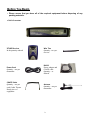
Before You Begin
• Please ensure that you have all of the required equipment before disposing of any
packing materials.
xTV9T4 Transmitter
XTV9R Receiver
Wire Ties
In the quantity ordered
Quantity – two per
receiver
Power Cord
Quantity – one per
transmitter
CSAFE Cable
Quantity – one per
each Cardio Theater
Ready piece of
equipment
Kit008
Power adaptor and
CSAFE cable
Quantity – as
ordered
Antenna
Quantity – one per
transmitter
3
Important Safeguards
Please read all of the safeguards before operating
this unit. Follow all warnings placed on the unit and
adhere to the operating and use instructions. Retain
this manual for future reference.
7. Heat - The unit should be located away from heat
sources such as radiators, heat registers, stoves, etc.
1. Power sources - Connect the unit to a power
source only of the type described in the operating
instructions or as marked on the appliance.
2. Power-cord protection - Route all power-supply
cords so that they are not walked on or pinched by
items placed upon or against them.
8.
Electric shock - Care should be taken so that
objects do not fall and liquid is not spilled on the
enclosure. If a metal object, such as a hairpin or
a needle, comes in contact with the inside of this
unit, a dangerous electric shock may result.
3. Grounding - Take precautions so that the
grounding or polarization means of the unit are not
defeated.
9. Enclosure removal - Never open the enclosure.
If the internal parts are accidentally touched, a
serious shock may occur.
4. Ventilation - Position the unit so that its location
does not interfere with ventilation. To maintain
good ventilation, do not put items on or over the
unit. Do not use the unit on a cushioned surface
that may block the ventilation openings.
10. Cleaning – Use a clean dry cloth. Do not use
solvents such as alcohol; paint thinner, etc. to
clean the unit.
5. Water and moisture - Do not locate the unit near
water.
11. Abnormal smell - If an abnormal smell is
detected, immediately turn the power OFF and
disconnect the power cord. Contact your dealer
or service center.
6. Temperature - The unit may not function properly
if used at extreme temperatures. The ideal
temperature is 41ºF (5ºC) to 87ºF (30ºC)
4
Important Safeguards - Continued
12. Stands - Any component stand should be moved
with care. Quick or excessive force would cause the
stand to overturn
14. Damage requiring service – The unit should be
serviced by a qualified Cardio Theater technician
when:
A. The power cord or the plug has been
damaged.
B. Objects have fallen on, or liquid has been
spilled into the unit.
C. The unit does not appear to operate normally
or exhibits a marked change in performance.
D. The unit has been dropped or the enclosure
damaged.
15. Servicing – The user should not attempt to
service the unit beyond that described in this manual.
All other servicing should be referred to a qualified
technician.
13. Nonuse periods – The power cord should be
disconnected when left unused for a long period of
time.
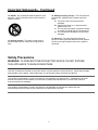
Safety Precautions
WARNING: TO PREVENT FIRE OR ELECTRIC SHOCK, DO NOT EXPOSE
THIS APPLIANCE TO RAIN OR MOISTURE.
CAUTION: TO REDUCE THE RISK OF ELECTRIC SHOCK, DO NOT REMOVE COVER (OR BACK). THERE ARE NO USERSERVICEABLE PARTS INSIDE. REFER SERVICING TO A QUALIFIED CARDIO THEATER TECHNICIAN.
THIS SYMBOL IS INTENDED TO ALERT THE USER TO THE PRESENCE OF UNINSULATED "DANGEROUS VOLTAGE"
WITHIN THE PRODUCT'S ENCLOSURE THAT MAY BE OF SIGNIFICANT MAGNITUDE TO CONSTITUTE A RISK OF
ELECTRIC SHOCK TO PERSONS.
THIS SYMBOL IS INTENDED TO ALERT THE USER TO THE PRESENCE OF IMPORTANT OPERATING AND
MAINTENANCE INSTRUCTIONS IN THE LITERATURE ACCOMPANYING THE UNIT.
5
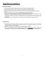
Suggestions for Installation
General Information
• Group the audio components in a single location to minimize cabling in the cardiovascular room.
• If the audio components are stacked in a stereo cabinet, ensure there is adequate ventilation.
• Place the xTV9T4 transmitter in a well-ventilated area with the front and back easily accessible.
• Place the transmitter antenna eight to twelve feet (8’-12’) from the floor to obtain the best possible transmission
range.
• Make sure the antenna is in the vertical position and within line of site to each receiver.
• The range of the xTV9T4 transmitter is a line of sight (300-foot diameter) from the transmitter antenna. (I.e., if you’re
within 150 ft. and can physically see the antenna, you should have good reception.)
• By adjusting the transmitters to transmit on different frequencies, you can have multiple xTV9T4 transmitters in the
same location. Up to 32 channels with the xTV product line and up to 52 with the older LCS product line (out of
production).
• Place the transmitter and audio equipment in a central location for best transmission coverage of the room.
xTV9R Receiver
• When attaching xTV Receivers to equipment, take care not to interfere with the normal operation of the equipment.
If the xTV Receiver is connected to a Cardio Theater ready piece of cardiovascular equipment, the connection
should not interfere with normal operation.
• If attaching the xTV Receiver to a control panel, avoid covering controls or indicators.
• Attach the xTV Receivers securely with the wire ties and 2” neoprene mounting pad provided. You should not be
able to rotate the receiver when it is properly attached. This is very important to prevent moisture and
perspiration from entering the receiver through the headphone jack or power connector on the back of the unit.
6
Controls and Indicators
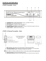
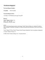
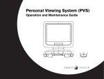
xTV9T4 Transmitter - Front
1.
2.
3.
4.
5.
6.
7.
Transmitter Select – Used to select transmitter output, 1-4 (program mode only).
Input Signal – For viewing audio input levels.
Power-on Indicator - Lights when main power switch is on.
On / Off Switch – Turns power on or off to transmitter
Transmitter indicator- Displays current transmitter selected for adjustment (program mode only).
Channel Indicator - Indicates current channel
Volume Indicator – Indicates volume level selected.
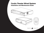
xTV9TX 4 Channel Transmitter – Back
1. Main Line Fuse - Main system fuse for the transmitter, T250ma time lag 5x20mm.
2. Power Input Connector - The power-input connector brings 120 Volts 60 Hz AC into the system.
3. 110 / 220 volt selector switch – Changes input voltage to the transmitter.
Caution: Make sure that the 110/220-volt selector is in the proper position before applying power
4. Antenna Connector - Connector for transmitter antenna.
5. Audio Input Connectors- Stereo RCA audio input connectors for cables from audio components.
7
Controls and Indicators
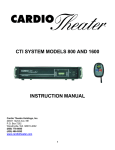
xTV9 Receiver
1.
2.
3.
4.
5.
Channel Display - Indicates current channel selected.
Channel Select - To select the desired listening channel.
EQ Tone - Adjusts audio to predefined EQ settings
Volume Adjust - To select desired listening volume.
Mute/Programming - Audio mute. Also used for putting unit into program mode.
8
System Connections
Transmitters
NOTE: MAKE ALL CONNECTIONS TO THE TRANSMITTER AND RECEIVERS WITH POWER
OFF.
Step 1
Connect the antenna to the antenna connector on the back of the xTV9T4 transmitter.
Step 2
Connect up to four (4) audio components to the stereo input jacks on the back of the xTV9T4 transmitter.
Step 3
Use the power cord supplied to connect the transmitter to AC power.
Caution: Make sure that the 110-220 volt selector switch is on the proper position before plugging unit in to AC
outlet
Step 4
ALL TV’s need external speakers off, not muted.
Receiver Power Connections
There are two (2) configurations for applying power to the xTV Receivers.
Contact the manufacturer of the cardiovascular equipment to determine if the unit is Cardio
Theater ready or can be retrofitted. The Cardio Theater Service Center can also be a source of
information for this and can be contacted at (800-776-6695). This will determine whether we
send power adapters or CSAFE cables for your system.
xTV Receiver with AC power adapter (wall bug)
For cardiovascular equipment that is not Cardio Theater Ready, power must be supplied via a power adapter
(wall bug) connected to a 120-volt outlet. The power adapter is connected to the xTV Receiver by a telephone
connector on the back of the unit.
xTV Receiver powered by cardiovascular equipment (CSAFE)
For cardiovascular equipment that is Cardio Theater Ready, power will be supplied via a connector located on the
cardiovascular equipment. The xTV Receiver is powered from the machine via an adapter cable that plugs into the
receiver and into the cardiovascular piece. There are different adapter cables available for most cardiovascular
machines on the market. Your sales person will need to know the make and model of each piece of cardiovascular
equipment that will be Cardio Theater Ready or retro-fittable (if you plan to retro-fit) at the time of the purchase of
the Cardio Theater system.
9
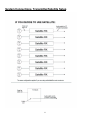
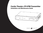
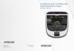
System Connections, Transmitter/TV Setup
10
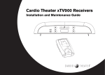
System Connections, Transmitter/Satellite Setup
11
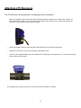
Attaching xTV Receivers
The xTV Receiver can be attached to virtually any piece of equipment.
•
Attach the supplied coiled control cable into the RJ45 telephone connector on the back of the receiver, as
shown below. Be careful to push the rubber boot firmly into the recess to form a tight seal around the
connector. Failure to do this may void your warranty.
•
Attach the supplied neoprene mounting pad to desired location on the exercise equipment.
•
Align the xTV Receiver over the mounting pad on the handle or rail.
•
Use two of the supplied plastic wire ties to attach the xTV Receiver to the handle or rail. Pull wire ties firmly to
secure and cut off the excess.
This method may be used to mount an xTV Receiver either horizontally or vertically.
12
xTV9T4 Transmitter Setup
NORMAL OPERATION
There are four modes that the transmitter can be in:
xTV US/Canada
xTV Australia
32 possible frequencies
16 possible frequencies
LCS US/Canada
LCS Australia
52 possible frequencies
24 possible frequencies
Upon power up, the display will show '88.88' briefly as a lamp test, then display briefly one of the four shown below to
indicate which of the four modes the transmitter is in:
xTV US/Canada
xTV Australia
'07.76'
'09.01'
LCS US/Canada
LCS Australia
'17.76'
'19.01'
Then the transmitter will enter normal operation, and the display will show '1 .NN' where NN is the frequency number
assigned to that channel. Pressing the Transmitter up/down button will increment the display through the 4 available
transmitters.
If there is not a frequency programmed for a transmitter, the two right digits on the display will be blank.
PROGRAMMING MODE
To enter programming mode, press and hold one of the four buttons while turning the power on. The display will show one
of the following, depending on which button is held:
LCS US/Canada
LCS Australia
('17.76') Transmitter Up button
('19.01') Transmitter down button
xTV US/Canada
xTV Australia
('07.76') Channel Up button
('09.01') Channel Down button
Note: xTV US/Canada is the most common setting. LCS US/Canada and LCS Australia modes are only used with older Cardio Theater
MaxJack and LCS receiver product lines (no longer in production). The two Australia modes are used for customers to limit the frequencies
to legal channels used in that country.
The display will continue to show one of those four until the held button is released. Then the display will show '1.XX'. The
'XX's correspond to the channel that is currently set on the transmitter.
To program a channel number for a transmitter, press the channel up or down button to scroll through the available
channels. When the desired channel number is displayed and is flashing, press and hold both the Channel up and
Channel down buttons at the same time, then release. The channel number will now be on steady, signifying that channel
is programmed for that transmitter.
You may 'unselect' a channel by the same method, and it will start blinking. A blinking channel number indicates that no
channel is selected and that particular transmitter will be turned off when you get out of program mode. If you try to select
a channel that is already selected by another of the four channels, your selection will be ignored and will revert back to
default blinking ‘01’.
Use the Transmitter up/down buttons to move to the next transmitter you want to program and follow the same steps
described above. Once you have selected the channels you want to transmit on, scroll through the four transmitters 1-4
using the Transmitter up or Transmitter down buttons, to check your selections. If a transmitter has a valid channel
programmed, it will appear on the right side of the display, and be on steady. If not, it will default to '01' and be blinking.
The transmitter will not allow you to use the same channel number twice.
To exit the programming mode and save your selections, press and hold both the Channel up button and the Transmitter
down button at the same time, then release both buttons. The unit will automatically restart in normal operation, with the
(new) programmed channels.
To exit without saving your changes, simply turn the unit off.
13
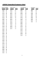
xTV9T4 Transmitter Frequency Chart
Cardio - United States
Cardio - Australia
xTV - United States
xTV - Australia
Frequency
Channel
Frequency
Channel
Frequency
Channel
Frequency
Channel
01
02
03
04
05
06
07
08
09
10
11
13
14
15
16
17
18
19
20
21
22
23
24
25
26
27
28
29
30
31
32
33
34
35
36
37
38
39
40
41
42
43
44
45
46
47
48
49
50
51
52
916.2
917.4
918.0
919.4
920.2
922.4
924.0
925.0
922.0
923.6
926.2
920.6
921.6
923.2
925.8
915.8
917.0
918.4
919.8
919.0
921.0
922.8
925.4
01
02
03
04
05
06
07
08
09
10
12
13
14
15
16
17
18
19
20
21
22
23
24
905.0
906.2
923.6
924.4
925.6
910.6
911.8
913.4
914.2
915.4
917.8
919.0
920.6
921.4
922.6
905.6
906.6
907.6
908.8
910.0
911.2
912.4
913.8
915.0
916.2
917.4
918.4
919.6
921.0
921.8
923.0
01
02
03
04
05
06
07
08
09
10
12
13
14
15
16
17
18
19
20
21
22
23
24
25
26
27
28
29
30
31
32
923.6
924.4
925.6
917.0
917.8
919.0
920.6
921.4
922.6
916.2
918.4
919.6
921.0
921.8
923.0
01
02
03
04
05
06
07
08
09
10
12
13
14
15
16
905.4
907.4
909.0
910.4
911.2
912.6
914.2
915.4
916.2
917.4
918.0
920.2
922.4
924.0
925.0
906.4
908.4
909.8
912.0
913.0
913.8
915.0
916.6
922.0
923.6
924.4
926.2
920.6
921.6
923.2
925.8
915.8
917.0
918.4
919.8
919.0
921.0
922.8
925.4
910.8
911.6
913.4
914.6
903.6
904.4
905.8
907.0
904.0
905.0
907.8
909.4
14
Programming the Receiver
The procedure outlined below must be followed, to set up your receivers for first time use or anytime a receiver is replaced.
Make sure that all transmitters that will used in the Club are on and operating before going through the
programming procedures below.
Note: Make sure that you program the receivers in the same mode that the transmitters are set
on.
Auto Program Mode:
1. The xTV receiver is a universal receiver that is capable of receiving the signal from other brands and models of
transmitters that are out in the marketplace.
To activate auto program mode, press both the Volume Up and Volume Down buttons simultaneously for 3
seconds. When the display reads “P-“ let go of the two buttons. The display will then read one of four numbers “1”, ”-2”, “-3”, or “-4”.
“-1” xTV program mode
“-2” Cardio Theater LCS program mode
“-3” Broadcast Vision program mode
“-4” 863Mhz program mode (for overseas use only)
2. Use the channel up or Channel down button to select the transmitter model or brand.
The display will show one of the four numbers listed above.
It is important to use the appropriate program mode to be able to pick up all the available channels for a
given transmitter brand.
3. Press the EQ / Tone button to begin programming. Scanning will take a few moments to lock in available
transmitter channels.
When auto programming is complete, press channel Up and Down buttons to confirm all transmitters have been
programmed. This feature can be effected by outside interference and may not automatically select all the available
channels or may select undesired channels. If this happens, go into the manual program mode to add or delete channels
as necessary.
Manual Program Mode:
Note: Auto program mode must be completed first or you will not be able to enter “Manual Mode”
1. To activate manual program mode, press Channel Up and Channel Down buttons simultaneously for 3 seconds.
When the “P-” shows up on the display, release the two buttons. Channel number “1” will then be displayed.
A flashing channel number indicates that the channel is inactive and a steady channel number will indicate
that the channel is active.
2. Use the EQ / Tone button to toggle the displayed channel number from either active or inactive as desired. Go
through all channels and do the same as above.
3. When manual programming is complete, press Mute button to lock channels and return to normal operation.
15
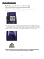
Receiver Maintenance
Replacing a worn Headphone Jack Assembly
Remove receiver from the cardio equipment.
On the back of the receiver remove the two inner screws on the bottom of the receiver
as shown below.
This will release the worn headphone jack assembly from the receiver.
Turn receiver over, remove the worn headphone jack assembly and discard. Replace it with a new
assembly. Make sure that the replacement headphone jack fits squarely into the recess of the
enclosure so that the spring-loaded contacts make full contact with the headphone jack assembly.
Re-install the screws removed previously, while holding the headphone jack firmly in place.
Install the repaired unit back onto exercise equipment using new wire ties. Make sure receiver fits
tightly on the neoprene mounting pad to prevent movement on the equipment.
16
Specifications
xTV9T4 –Transmitter
Transmission bandwidth....................……….... 902 MHz to 928 MHz
Frequency Range......................................…….. adjustable from 905.4 MHz to 926.2 MHz.
Available Channels……………………….…….... 32 channels xTV mode, 52 Cardio LCS mode
Transmission Power.................................…….. 95 dbmv max.
Transmission Range.................................…….. 150 ft. from antenna
Power Consumption.................................…….. 25 watts max.
Audio Inputs.............................................……... 4
Dimensions................................................…….. W: 19.00" / 48.26 cm
H: 3.87" / 9.83 cm
D: 14.75" / 37.46 cm
Weight......................................…….................... 7.5 lbs. / 3.4 kg
xTV Receiver
Output Level / Load Impedance..............……... 550 mV / 32 Ohm.
Dimensions................................................…….. W: 2.70” / 68.6 mm
H: 4.25” / 108 mm
D: 1.50” / 38 mm
Weight.....................................................………. 3 oz / 85 g
17
Limited Warranty
PLEASE READ THESE WARRANTY TERMS AND CONDITIONS CAREFULLY BEFORE USING YOUR CARDIO THEATER PRODUCT. BY USING
THE EQUIPMENT, YOU ARE CONSENTING TO BE BOUND BY THE FOLLOWING WARRANTY TERMS AND CONDITIONS.
Limited Warranty.
Precor Incorporated (“Precor”) warrants all new Cardio Theater products to be free from defects in
materials and manufacture for the warranty periods set forth below. The warranty periods
commence on the invoice date of the original purchase. This warranty applies only against defects
discovered within the warranty period and extends only to the original purchaser of the product.
Parts repaired or replaced under the terms of this warranty will be warranted for the remainder of
the original warranty period only. To claim under this warranty, the buyer must notify Precor or your
authorized Cardio Theater dealer within 30 days after the date of discovery of any nonconformity
and make the affected product available for inspection by Precor or its service representative.
Cardio Theater products deemed defective by a Precor representative, will be issued a return
authorization number. Precor will not accept returns without a return authorization number.
Precor reserves the right, at their option, to repair or replace the product after verification of defect.
Product that fails after the warranty period expires will be repaired or replaced at the current part
and labor pricing after authorization from the customer. Repairs are warranted for 90 days.
Precor’s obligations under this warranty are limited as set forth below.
Warranty Periods and Coverage.
Disclaimer and Release.
The warranties provided herein are the exclusive
warranties given by Precor and supersede any
prior, contrary or additional representations,
whether oral or written. ANY IMPLIED WARRANTIES,
INCLUDING THE WARRANTY OF MERCHANTABILITY
OR FITNESS FOR A PARTICULAR PURPOSE THAT
APPLY TO ANY PARTS DESCRIBED ABOVE ARE
LIMITED IN DURATION TO THE PERIODS OF
EXPRESS WARRANTIES GIVEN ABOVE FOR THOSE
SAME PARTS. PRECOR HEREBY DISCLAIMS AND
EXCLUDES THOSE WARRANTIES THEREAFTER.
Some States do not allow limitations on how long
an implied warranty lasts, so the above limitation
may not apply to you. PRECOR ALSO HEREBY
DISCLAIMS AND EXCLUDES ALL OTHER
OBLIGATIONS OR LIABILITIES, EXPRESS OR IMPLIED,
ARISING BY LAW OR OTHERWISE, WITH RESPECT
TO ANY NONCONFORMANCE OR DEFECT IN ANY
PRODUCT, INCLUDING BUT NOT LIMITED TO:
(A) ANY OBLIGATION, LIABILITY, RIGHT, CLAIM OR
REMEDY IN TORT, WHETHER OR NOT ARISING FROM
THE NEGLIGENCE OF PRECOR OR ITS SUPPLIERS
(WHETHER ACTIVE, PASSIVE OR IMPUTED); AND (B)
ANY OBLIGATION, LIABILITY, RIGHT, CLAIM OR
REMEDY FOR LOSS OF OR DAMAGE TO ANY
PRODUCT. This disclaimer and release shall apply
• Cardio Theater Transmitters
xTV-T Wireless or Wired Floor Models
xTVFM system transmitter
3 Year
Parts & Labor
• Cardio Theater Receivers
XTV-R Wireless or Wired Upper Models
XTVFM system receiver
1 Year
Parts & Labor
• Cardio Theater LCD Screen (PVS)
• Cardio Theater Screen Controllers
• Quick Change Headphone Jack
1 Year
1 Year
90 Day
Parts & Labor
Parts & Labor
Parts Only
even if the express warranty set forth above fails of
its essential purpose.
• Optional DVD Player
1 Year
Parts
For any product described above that fails to
conform to its warranty, Precor will provide, at their
option, one of the following: (1) repair; (2)
replacement; or (3) refund of the purchase price.
Limited Warranty service may be obtained by
contacting the authorized dealer from whom you
purchased the item. Precor compensates Servicers
for warranty trips within their normal service area to
repair commercial product at the customer’s
location. You may be charged a trip charge outside
the service area. THESE SHALL BE THE SOLE AND
Exclusive Remedies.
Conditions and Restrictions.
This warranty is valid only in accordance with the conditions set forth below:
1. The warranty applies to the Cardio Theater product only while
a. it remains in the possession of the original purchaser and proof of purchase is
demonstrated,
b. it has not been subjected to accident, misuse, abuse, improper service, or mechanical,
electrical or non-Precor modification,
c. claims are made within the warranty period.
2. This warranty does not cover damage or product failure caused by electrical wiring not in
compliance with electrical codes or Precor owner’s manual specifications, or failure to provide
reasonable and necessary maintenance as outlined in the owner’s manual. This warranty
excludes misuse or failures of, for example, poor quality CD’s, multiple discs inserted in
the player, failures caused by home-produced copies of discs, etc.
3. Except in Canada, Precor does not pay labor outside the United States.
4. Warranties outside the United States and Canada may vary. Please contact your local Dealer
for details.
This Limited Warranty shall not apply to:
1. Software (PROM) version upgrades.
2. Normal wear and tear, consumables and cosmetic items, including, but not limited to
the following: labels.
3. Repairs performed on Cardio Theater products missing a serial number or with a serial tag
that has been altered or defaced.
4. Service calls to correct installation of the product or instruct owners on how to use
the product.
5. Pickup and delivery involved with repairs.
6. Any labor costs incurred beyond the applicable labor warranty period.
7. The user is cautioned that changes or modifications not expressly approved by the
manufacturer of the product could void the user’s authority to operate the product.
Complete this portion and keep for your records.
Purchased From: ____________________________ Example: Dealer or store name.
Phone Number: _____________________________ Example: Dealer or store telephone number.
Product/model: _____________________________ Example: Transmitters, Receivers
Serial number: ______________________________
The serial number is found on the shipping container or item.
EXCLUSIVE REMEDIES OF THE BUYER FOR ANY
BREACH OF WARRANTY.
EXCLUSION OF CONSEQUENTIAL
AND INCIDENTAL DAMAGES.
PRECOR AND/OR ITS SUPPLIERS SHALL HAVE NO
OBLIGATION OR LIABILITY, WHETHER ARISING IN
CONTRACT (INCLUDING WARRANTY), TORT
(INCLUDING ACTIVE, PASSIVE, OR IMPUTED
NEGLIGENCE AND STRICT LIABILITY), OR
OTHERWISE, FOR DAMAGE TO THE PRODUCT,
PROPERTY DAMAGE, LOSS OF USE, REVENUE OR
PROFIT, COST OF CAPITAL, COST OF SUBSTITUTE
PRODUCT, ADDITIONAL COSTS INCURRED BY
BUYER (BY WAY OF CORRECTION OR OTHERWISE)
OR ANY OTHER INCIDENTAL, SPECIAL, INDIRECT, OR
CONSEQUENTIAL DAMAGES, WHETHER RESULTING
FROM NONDELIVERY OR FROM THE USE, MISUSE
OR INABILITY TO USE THE PRODUCT. This
exclusion applies even if the above warranty fails
of its essential purposes and regardless of whether
such damages are sought for breach of warranty,
breach of contract, negligence, or strict liability in
tort or under any other legal theory. Some states
do not allow the exclusion or limitation of incidental
or consequential damages, so the above limitation
may not apply to you.
This warranty gives you specific legal rights, and
you may also have other rights, which vary from
state to state.
Effective 21 January 2005
P/N CX30037-101
18
Technical Support
Technical Support Number
Telephone
1-800-776-6695
Technical Support Hours:
7:00 AM to 3:30 PM Monday through Friday PST
Write to:
Cardio Theatre Holdings, Inc.
20031 142nd Ave. NE
Woodinville, WA 98072-4002
Notice
Due to continuing advancements in technology, Cardio Theatre Holding, Inc. reserves the right to
make changes in hardware, packaging, and any accompanying documentation without prior written
notice.
Cardio Theater PVS and Cardio Theater Quick Change Headphone Jack are registered trademarks
of Cardio Theatre Holdings, Inc.
© 2004 Cardio Theatre Holdings, Inc., all rights reserved
19