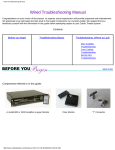
1
Cardio Theater Wired System
Installation and Maintenance Guide
™
®
CHANNEL
VOLUME
®
Important Safety Instructions
Regulatory Information
Always follow basic safety precautions when using this
equipment to reduce the chance of injury, fire, or damage.
Radio Frequency Interference (RFI)
• Read all instructions in this guide before installing and using the
equipment. Follow any labels on the equipment.
Federal Communications Commission, Part 15
• Use the power adapter provided with the equipment. Plug the
power adapter into an appropriate, grounded power outlet as
marked on the equipment.
• the IEC EMC Directive (international electromagnetic
compatibility certification)
• Make sure that the equipment has adequate ventilation. Do not
place anything on top of or over the equipment. Do not use on a
cushioned surface that could block the ventilation openings.
• Keep the equipment away from water and moisture.
• Locate the equipment away from sources of heat, such as
radiators, heat registers, and stoves. Avoid temperature
extremes.
• the limits for a Class A digital device, pursuant to Part 15 of the
FCC Rules. These limits are designed to provide reasonable
protection against harmful interference in a residential
installation. The unit generates, uses, and can radiate radio
frequency energy and, if not installed and used in accordance
with the owner’s manual instructions, may cause harmful
interference to radio communications.
WARNING
Per FCC rules, changes or modifications
not expressly approved by Precor could
void the user’s authority to operate the
equipment.
• Avoid dropping anything on or spilling anything inside the
equipment because doing so can damage the electronics.
European Applications
• Do not attempt to service the unit yourself except to follow the
maintenance instructions found in this guide.
This product conforms to the requirements of the European
Council Directive 89/336/EEC, Electromagnetic Compatibility.
This product also conforms to the requirements of the European
Council Directive 73/23/EEC, Low Voltage Directive.
Installation and Maintenance Guide: Important Safety Instructions
IMPORTANT SAFETY INSTRUCTIONS
• Position power cables so that they are not walked on or
pinched by items placed upon or against them.
The unit has been tested and found to comply with
1
Table of Contents
Important Safety Instructions ...............................................1
Regulatory Information .................................................................. 1
Install Controllers on the Exercise Equipment .............. 13
Set Up the Wired Floor Units .............................................. 15
Before You Begin .....................................................................3
About the Controller ...................................................................... 4
Obtaining Service ........................................................................... 4
Place QuadPac Wired Amplifier ........................................ 16
Preparations ..............................................................................5
Unpacking the Equipment ............................................................ 5
Required Tools ................................................................................ 6
Installation Requirements .............................................................. 6
Maintenance and Troubleshooting ................................... 19
Cleaning and Periodic Checks ..................................................19
Troubleshooting the Wired System .........................................19
Replacing the Headphone Jack ................................................21
Install the Distribution Unit .................................................10
Limited Warranty .................................................................... 22
Connect the System Together ............................................ 17
Adjust Sound Levels on the Distribution Unit ................12
Installation and Maintenance Guide: Table of Contents
2
Before You Begin
With the Cardio Theater Wired System, fitness facilities can add
entertainment to exercise rooms while providing high-quality sound
to its members. The Cardio Theater Wired System gives people the
choice of listening to music, radio, or programs shown on TVs while
they exercise. The person simply plugs a stereo headphone into a
controller, selects the desired entertainment, and exercises while
listening to high-fidelity sound. The digitized sound of the Cardio
Theater Wired System eliminates possible background hissing and
popping sounds.
A typical Cardio Theater Wired System includes a Model 800 or
1600 Distribution Unit, a number of controllers, a number of wired
lower units, and connectors, cables, and more as ordered.
Depending on the size of the installation, you may need to install one
or more QuadPac Wired Amplifiers, which will allow the facility to
connect additional controllers or to include exercise equipment
farther away than supported by the distribution unit.
The Model 800 Distribution Unit has 8 channels; the Model 1600
Distribution Unit has 16 channels. Depending on the distribution unit
being installed, the fitness facility can offer up to 8 or 16 different
types of entertainment at one time, to people listening with
controllers. A public address feature lets the facility interrupt the
current sound entertainment with important information for people
exercising.
Installation and Maintenance Guide: Before You Begin
A fitness facility chooses to install the Cardio Theater Wired System
when a wireless system cannot be installed due to foreseen conflicts
with other wireless equipment, or the location makes it inadvisable.
This guide explains how to install a distribution unit, controllers, and
wired lower units. It also includes installation instructions for a
QuadPac Wired Amplifier if needed. For proper installation, please
read this guide thoroughly and follow the instructions.
Note: In earlier Cardio Theater Wired System manuals, the names
for parts of the system were different. Table 1 lists the old name and
gives the name currently used.
Table 1: Name changes
Old Name
New Name
Main amplifier
Distribution unit
Upper monitor box
Controller
Floor monitor
Lower monitor
Wired floor unit
3
About the Controller
Obtaining Service
The controller supports up to 16 channels of high-fidelity sound
depending on the distribution unit installed. Use of the controller is
intuitive; people can typically use the controller with little or no
training. Figure 1 provides an overview of how to use the controller.
Do not attempt to service any of the equipment provided in the
Cardio Theater Wired System except as described in this guide. For
information about product operation or service, refer to the Cardio
Theater web site at www.cardiotheater.com or contact an authorized
dealer. For information about product operation or service, contact
an authorized Cardio Theater Technical Support Representative:
• 1-800-776-6695 or [email protected]
• +44 118 973 9633 or [email protected]
Returning Equipment to Cardio Theater
Channel buttons let
you scroll through
available channels.
CHANNEL
VOLUME
Volume buttons let
you adjust the
sound level.
Figure 1: How to use the buttons on the controller
To return equipment to Cardio Theater for any reason, you must
contact Cardio Theater Technical Support and obtain a return
authorization (RMA) number. When requesting the RMA number,
explain why you are returning the equipment, for example you
ordered too many controllers and the extra controller can be
returned to stock, or the equipment needs repairs.
Important: Equipment must be shipped with an RMA number in
order for Cardio Theater to process it. Any equipment received
without an RMA number will be returned to the sender.
During installation, the technician attaches controllers to selected
exercise equipment in the facility. Next, the technician installs a wired
floor unit on the floor near each piece of equipment, and then
attaches the nearby controller with a coiled cable; each controller
requires a wired floor unit.
Controllers are powered by the distribution unit through the coaxial
cables that link wired floor units to the distribution unit. Therefore,
additional power cables are not required for the controllers.
Installation and Maintenance Guide: Before You Begin
4
Preparations
Remember to read and follow the instructions in this guide. If you do
not install the Cardio Theater Wired System according to these
instructions, you could void the Limited Warranty.
• Multiple wired floor units (CX2002F), 1 for each controller
Unpacking the Equipment
The Cardio Theater Wired System is shipped with the following
items:
• Distribution unit, Model 800 or 1600 (CXC800 or CXC1600)
• Coaxial cables for wired floor units, quantity and lengths as ordered
• T-Connector, 1 per wired floor unit
• Terminators, 2 for Model 800 or 4 for Model 1600 Distribution Unit
• If needed, QuadPac Wired Amplifier, 1 to 4 as ordered
®
• Power cable for distribution unit
• RCA audio cables for distribution unit, quantity as ordered
• Multiple controllers (CX2004U), quantity as ordered
• Coiled cables, 1 per controller
• Neoprene pad, 1 per controller
• Wire ties, 4 per controller
• For each QuadPac Wired Amplifier, an AC power adapter for each
output connector that will be used
• Numbered signs to post near TVs and audio components
• These installation instructions
If any items are missing, contact the dealer from whom you
purchased the Cardio Theater Wired System or call Cardio Theater
Technical Support.
Installation and Maintenance Guide: Preparations
5
Required Tools
Obtain the following before installation:
• Phillips-head (crosshead) screwdriver
• Headphones
• Tool to cut the wire ties
• Pliers to tighten the wire ties
Installation Requirements
Review the following installation requirements before assembly. This
section provides important information you need to know to properly
install a Cardio Theater Wired System.
General Information
• The Model 800 Distribution Unit has eight stereo channels (eight
audio inputs) and two output connectors. The Model 1600
Distribution Unit has 16 stereo channels and four output
connectors. You can connect a different audio component to each
channel. For example, with a Model 800 Distribution Unit, you
could connect five TVs and three radio stations to its eight audio
inputs.
Each output connector on the distribution unit supports up to 20
controllers. This means that the Model 800 Distribution Unit
supports up to 40 controllers and the Model 1600 Distribution
Unit supports up to 80 controllers. For an overview of a Wired
System installation, refer to Figure 2.
• Cardio Theater recommends that you group audio components
together to minimize cabling.
• If the audio components are stacked in a cabinet, make sure the
equipment has adequate ventilation to avoid overheating.
Installation and Maintenance Guide: Preparations
• Place the distribution unit in a location where the front and back of
the unit are easily accessible. The distribution unit requires 1 inch
(3 cm) of clearance on each side for ventilation.
• Televisions should be arranged so that every person exercising
has a clear view of the screens. Stagger the rows of exercise
equipment, placing shorter equipment, such as recumbent cycles,
in the front and taller equipment, such as elliptical crosstrainers, in
the back.
• Number the TVs and audio components to match the
corresponding channel selections that people will use on the
controllers. Most likely you will want to place the numbered signs
in front of the TVs and audio components in a logical order to
make it easier for people.
Installing Controllers
• You can attach controllers to the handlebars of almost any
exercise equipment. However, for safety, the controller must be
installed on a stationary location, so you cannot install it on
handlebars that move.
• Attach the controllers securely with the wire ties and neoprene
pads. When a controller is properly attached to a piece of
equipment, it should not move. Proper installation is important to
prevent moisture from entering the controller through the power
connector and damaging the electronics.
• Each controller requires a wired floor unit; a coiled cable connects
the two together. After installation, make sure that the coiled cable
does not interfere with using the exercise equipment.
• As possible, divide the controllers evenly between output
connectors on the distribution unit. For example, if you have 20
controllers and a Model 800 Distribution Unit, connect 10
controllers to its two output connectors rather all 20 controllers on
one output connector.
6
TV
TV
TV
TV
TV
This model supports 8 audio components.
Model 800
Distribution Unit
®
Input
Signal
ON
POW ER
OFF
Channel
Volume
This model has
2 output connectors.
Each controller connects
to a wired floor unit.
A terminator is
required on the last
wired floor unit.
Coaxial cable connects wired
floor units to each other and the
distribution unit.
A line of coaxial cables can
run 400 feet (120 meters).
Up to 20 controllers can be connected
to each line of coaxial cables.
Figure 2: Overview of a Cardio Theater Wired System installation
Installing Wired Floor Units
• Wired floor units are connected to the distribution unit using
coaxial cables. You can install the wired floor units and the
associated coaxial cables under the floor, either in a sub-floor or
conduit. You can also use an above-floor conduit system, such as
a rubber raceway, to protect the coaxial cables. A rubber raceway
is a narrow cable cover with beveled edges and a low profile that
will not interfere with traffic flow. It may be secured to the floor with
double-sided cloth carpet tape.
Installation and Maintenance Guide: Preparations
• The wired floor units must be secured to the floor or sub-floor to
ensure that they remain stationary. The wired floor units may be
secured using screws through the mounting holes or strong
double-sided cloth carpet tape.
• Do not attach wired floor units to exercise equipment. Movement
caused by people exercising on the equipment or from elevating a
treadmill will cause problems with wired floor units if they are
attached to the equipment.
7
Installing QuadPac Wired Amplifiers
• QuadPac Wired Amplifier lets a facility expand the number of
controllers supported by a distribution unit. With a QuadPac
Wired Amplifier, you can add up to 80 additional controllers,
basically 20 controllers for each output connector on the wired
amplifier. For example, this means a Model 1600 Distribution Unit,
which normally supports 80 controllers, when cabled with a single
QuadPac Wired Amplifier, can support up to 160 controllers. See
Figure 3.
Controllers
Model 1600
Distribution Unit
1
2
3
4
5
20
1
2
3
4
5
20
1
2
3
4
5
20
1
2
3
4
20
5
• You can connect two QuadPac Wired Amplifiers to a Model 800
Distribution Unit (one for each output); four wired amplifiers can
be connected to a Model 1600 Distribution Unit.
• A site can also use a QuadPac Wired Amplifier to support
exercise equipment located farther away than 400 feet
(120 meters), which is the limit supported by the distribution unit.
The QuadPac Wired Amplifier adds an additional 400 feet
(120 meters). This means a facility can support exercise
equipment located up to 800 feet (240 meters) away. You might
add a wired amplifier, for example, if the club has two separate
rooms that are at a distance from each other.
• Each output connector on the wired amplifier that will be used
requires an AC power adapter. The AC power adapter provides
power to the controllers connected (through coaxial cable) to the
output connector.
• Unused output connectors on the QuadPac Wired Amplifier do
not require a terminator, unlike the output connectors on a
distribution unit.
QuadPac
Terminators
1
2
3
4
5
20
1
2
3
4
5
20
1
2
3
4
5
20
1
2
3
4
5
20
Controllers
Figure 3: A QuadPac Wired Amplifier adds up to 80 ports
Installation and Maintenance Guide: Preparations
8
Connecting the Wired System Together
• When connecting televisions, use the “Audio Out” or, preferably,
“Line Out” connectors. If you are using televisions with Audio Out
connectors, the external speakers must be turned off and the
volume set to a reasonable, medium level to ensure that the
available sound is not too loud or distorted for people using the
controllers.
CAUTION: When connecting tuners or receivers, make sure that
you connect to the “Record Out” or “Line Out” connectors. Do
not use the “Speaker Out” connection because it may damage
the distribution unit.
• Connect one coaxial cable to each output connector on a
distribution unit; the maximum length of a coaxial cable is 400 feet
(120 meters). As you connect cables, label them and use a
descriptive name, such as “Treads 1” or “Rows 3 & 4,” to avoid
guesswork in the future.
Controllers
Model 800
Distribution Unit
• You must use 50 ohms impedance coaxial cable, such as
RG58/U, which is normally sold with the Cardio Theater Wired
System. Cardio Theater offers the coaxial cable in a variety of
lengths for connecting a wired system together. Do not substitute
any other cables or connectors for those specified and provided
with the Cardio Theater Wired system.
Do not use splitters on the coaxial
cables. Each cable run must originate
from an oupt connector.
1
2
3
4
5
20
1
2
3
4
5
10
1
2
3
4
5
10
Figure 4: Do not split the main cable run
• Each coaxial cable from the distribution unit must be terminated
with a terminator provided with the unit. If the terminator is not
installed on the last wired floor unit at the end of the cable, all
controllers on that line will experience poor sound quality. If a
cable run from the distribution unit includes a QuadPac Wired
Amplifier, you must install a terminator at the end of each cable
from the wired amplifier as well.
• Unused output connectors on the distribution unit must have a
terminator attached to the connector. You do not need to install a
terminator on any unused output connectors on a QuadPac Wired
Amplifier.
Note: By using a QuadPac Wired Amplifier, you can increase the
distance between controllers and the distribution unit an
additional 400 feet (120 meters) for a total distance of 800 feet
(240 meters).
Important: Do not use splitters on the coaxial cables, even if the
total number of controllers is supported (that is, 20 controllers).
Using splitters on a coaxial cable will cause interference and
poor sound quality. See Figure 4.
Installation and Maintenance Guide: Preparations
9
Install the Distribution Unit
1. Place the distribution unit where it will operate. Make sure that it
is located in a well-ventilated area with both the front and back
easily accessible.
2. Connect one end of the RCA audio cable to a TV or audio
source. Observe and follow the color coding of the RCA audio
cable connectors. If available, connect the RCA audio cable to
the Line Audio Output connector on the TV or audio source.
The Line Audio Output connector is recommended because it
always provides a consistent sound level and cannot be modified
by users.
CAUTION: When connecting tuners or receivers, make sure
that you connect to the “Record Out” or “Line Out” connectors.
Do not use the “Speaker Out” connection because it may
damage the distribution unit.
3. Connect the other end of the RCA audio cable to the audio
inputs on the distribution unit. Observe and follow the color
coding of the RCA audio cable connectors. The Model 800
Distribution Unit has 8 audio inputs and the Model 1600
Distribution Unit has 16 audio inputs. See Figure 5.
Output #1
2 Amp
Serial No.
CAUTION
TO REDUCE RISK OF ELECTRIC SHOCK
DO NOT REMOVE COVER.
NO USER SERVICEABLE PARTS INSIDE.
REFER SERVICE TO QUALIFIED SERVICE PERSONNEL.
16
D
C
15
14
13
12
11
10
2
A
M
P
A
M
P
B
Pin
Description
Pin 1
Input for PA microphone
Pin 2
Ground return for PA microphone
Pin 3
Pin 4
When pins 3 and 4 connected, engages PA
microphone
P.A. Input
8
R
5. If desired, connect the public address system to the PA Input
terminals on the distribution unit. Connect to the terminals as
follows:
4 3 2 1
2
9
Important: Keep RCA audio cables away from the power cable,
because the power cable may cause interference with the RCA
audio signal
Connecting pins 3 and 4 causes the microphone to be heard on
all channels. When the microphone is on so someone can speak,
the sound on all channels cuts out; sound returns on all channels
when the microphone is off (pins 3 and 4 are not connected).
You should connect a switching device that lets you connect
(short) pins 3 and 4 when needed, placing the on/off switch near
the PA microphone for convenience. Also, the microphone
should be low impedence with 600 ohm output resistance.
Follow color coding when connecting
RCA audio cables.
Output #2
2 Amp
4. Repeat steps 2 and 3 to connect additional TVs and audio
sources to the distribution unit.
7
6
5
4
3
A
2
1
Activation switch
R
110
220
L
L
Audio inputs
Input and
ground for
microphone
TO REDUCE RISK OF ELECTRIC SHOCK
DO NO REMOVE COVER.
NO USER SERVICEABLE PARTS INSIDE.
REFER SERVICE TO QUALIFIED SERVICE PERSONNEL
Figure 5: Connect RCA cables to audio inputs on the back of
distribution unit
Figure 6: Connections for attaching a public address system
Installation and Maintenance Guide: Install the Distribution Unit
10
6. Make sure the voltage selector on the back of the distribution
unit is set to the correct voltage for your location: 110 or 220.
CAUTION: The voltage on the distribution unit must be set to
the proper voltage for the location to avoid damaging the unit.
7. Plug the power cable, packaged with the distribution unit, into
the back of the unit.
8. Plug the power cable into a nearby power outlet.
Installation and Maintenance Guide: Install the Distribution Unit
11
Adjust Sound Levels on the Distribution Unit
Whenever a TV or audio component is connected to the distribution
unit, you should adjust the sound level to make sure that its level is
not too high or distorted. Once you set the sound level, the
distribution unit saves the settings and retains them in memory, even
when it is turned off.
Note: If you connected the RCA audio cable to the Line Audio
Output connector on a TV or audio component, you can skip this
procedure. Line Audio Output maintains a consistent level of sound
and cannot be modified by people using the controllers.
6. Use the Channel ▲ and ▼ buttons to select the desired channel.
The display shows the current channel selection (on the left). If
you are initially installing the distribution unit, start with channel 1
so you can move sequentially through the channels. If the
selected channel has little sound, such as quiet conversation or a
soft passage of music, wait for a normal signal before continuing.
See Figure 8.
1. Turn on TVs and other audio components connected to the
distribution unit.
2. If connected to a TV, turn off its speakers using the appropriate
menu function.
Channel
buttons
3. Adjust the volume on each TV or audio component so it is set to
a reasonable, medium level.
4. Turn on the distribution unit. As the distribution unit starts up, the
Power light and Input Signal lights will turn on for 5 seconds,
while the display shows the software version number.
5. Plug headphones into the jack located on the front of the
distribution unit (under the power switch). See Figure 7.
Headphone jack
Volume
buttons
Figure 8: Use Channel and Volume buttons to adjust sound levels
for each channel
7. Use the Volume ▲ and ▼ buttons to adjust the sound to a
comfortable level. As you press the buttons, the numbers on the
right in the display change. Observe the Input Signal lights and
adjust the sound as high as possible without causing the red
lights to come on. You have gone too far if the red lights flash
frequently or glow solidly. In this case, reduce the volume until
the red lights barely flash. See Figure 8.
8. Listen for approximately 30 seconds to make sure you are
satisfied with the volume level.
9. Repeat steps 6 to 8 for each remaining channel.
Figure 7: Location of headphone jack on distribution unit
Installation and Maintenance Guide: Adjust Sound Levels on the Distribution Unit
12
Install Controllers on the Exercise Equipment
1. Identify the equipment on which you plan to attach the
controllers.
Important: Make sure that the rubber boot securely covers the
connector to prevent moisture damage, or you could void the
Limited Warranty.
You can attach controllers to almost any exercise equipment.
2. Determine where on the equipment you will install each
controller. When you choose a location for the controller, make
sure that a person can comfortably reach it and that its controls
are easily readable. Also, make sure that the controller does not
interfere with the equipment’s display console or moving parts.
4. Attach the neoprene mounting pad to the desired location on the
handlebar. See Figure 10.
You can attach a controller either horizontally or vertically. You
cannot attach a controller to handlebars that move.
3. Connect the coiled cable into the RJ11 connector on the back of
the controller. Push the rubber boot firmly into the recess around
the connector to ensure a tight seal. See Figure 9. (You will plug
the other end of the coiled cable into the wired floor unit in the
next procedure.)
Figure 10: Install the mounting pad to the handlebar
5. Insert two wire ties through the holes in the mounting bracket on
the back of the controller.
6. Place the controller on the neoprene mounting pad, and then
attach it to the handlebar using the wire ties. See Figure 11. Use
the pliers to tighten the wire ties so the controller cannot move.
Important: Be sure to secure the controller on the handlebar so
that it does not move. If the controller moves, it may damage the
exercise equipment as well as itself, and void the Limited
Warranty.
Figure 9: Back of controller showing cable being connected
Installation and Maintenance Guide: Install Controllers on the Exercise Equipment
13
Figure 11: Install the controller on the handlebar with wire ties
7. Cut off the excess plastic from the wire ties, being careful not to
leave any sharp edges on the wire ties.
8. Repeat the above steps for each controller that you plan to
install.
Installation and Maintenance Guide: Install Controllers on the Exercise Equipment
14
Set Up the Wired Floor Units
1. Place a wired floor unit on the floor near each controller. Each
controller requires a wired floor unit to connect to the distribution
unit.
3. To speed cabling later on, connect a T-Connector to each wired
floor unit. See Figure 13.
2. Remove the cover on each wired floor unit by unscrewing two
screws. You will need a Phillips-head (crosshead) screwdriver to
remove the screws. Place the screws and covers in a safe
location; you will re-install them later. See Figure 12.
Remove these two screws to
remove cover.
T-connector
Figure 13: Connect T-connector to speed cabling later
Figure 12: If installed, remove cover
Installation and Maintenance Guide: Set Up the Wired Floor Units
15
Place QuadPac Wired Amplifier
1. If you have purchased this equipment, place each QuadPac
Wired Amplifier where it will operate. Make sure that it is located
in a well-ventilated area with both the front and back easily
accessible.
2. Put together each supplied AC power adapter, plugging the AC
power cord into the DC power box.
3. Plug each supplied AC power adapter into the power adapter
connectors on the back of the wired amplifier(s). You need an AC
power adapter for each outlet that will be used. See Figure 14.
(You will plug the other end of the power adapter into a power
outlet later in the process, after attaching the cables.)
Power adapter connectors
®
Figure 14: Plug AC power adapter(s) into QuadPac Wired
Amplifier
Installation and Maintenance Guide: Place QuadPac Wired Amplifier
16
Connect the System Together
1. Identify the coaxial cables required to connect the wired floor
units to each other and to the distribution unit, as well as to any
QuadPac Wired Amplifiers if used. Lay out the cables as
appropriate.
Each output from the distribution unit supports up to 20
controllers. To balance the system, try to evenly divide the
controllers between the outputs. For example, if your site will
have 30 controllers and you will be using a Model 800
Distribution Unit, install 15 controllers on each output.
2. Connect the coaxial cables to the output connectors on the
distribution unit. We recommend that you connect the cables to
the outputs as follows:
• If connecting one cable, connect to output A.
• If connecting two cables, connect to outputs A and C.
• If connecting three cables, connect to A, B, and C.
• If connecting four cables, connect to A, B, C, and D.
3. Label each cable connected to the distribution unit so you know
what controllers will be served by this cable run.
5. Start cabling wired floor units together. Connect the coaxial
cables to each side of the T-Connector in each wired floor unit.
See Figure 15.
T-Connector
Figure 15: Connecting a wired floor unit
6. When you reach the last wired floor unit for a run of cable from
an output connector, attach a terminator to the last T-Connector.
See Figure 16.
Important: You must terminate the cable connected to each
output connector to ensure good sound quality.
4. If any output connectors on the distribution unit do not have
coaxial cables connected, attach a terminator to the output
connector.
Important: The output connectors on the distribution unit must
be terminated, with a terminator installed on an unused
connector or on the last wired floor unit on the cable run. Refer
to Figure 16. If the output connector is not terminated, the
controllers may provide poor sound quality.
Installation and Maintenance Guide: Connect the System Together
Terminator
Figure 16: Install a terminator on the last wired floor unit
17
7. If your site will use a QuadPac Wired Amplifier, connect the
coaxial cable from the distribution unit to the Coax Input
connector on the front of the wired amplifier. See Figure 17.
Coax Input
connector
®
Input
Power
Signal
Figure 17: Attach the cable from the distribution unit to the
Coax Input connector
8. If you are installing a QuadPac Wired Amplifier, continue to
connect wired floor units together as described in steps 5 and 6.
Be sure to install a terminator at the end of each cable run.
9. Repeat steps 7 and 8 for each QuadPac Wired Amplifier that will
be installed.
13. If you are installing QuadPac Wired Amplifier(s), plug the AC
power adapter(s) into a power outlet. The Power light located on
the front of the wired amplifier lights.
14. Turn on the distribution unit. If your site is using a QuadPac
Wired Amplifier, the Signal light on the amplifier lights.
15. Using a controller, make sure the sound levels provided by the
distribution unit are consistent across all channels. Plug
headphones into a controller, then move through the channels,
listening to the sound level and checking for disturbing or
noticeable differences as you switch channels. If necessary,
adjust the volume level by using the Volume buttons on the
distribution unit.
16. Check each controller to ensure that it receives sound on the
appropriate channels, and that it provides high-quality sound for
each channel.
17. Place the appropriate numbered signs by each TV or audio
component. People will use the number on each sign to select
the desired entertainment.
10. Connect each controller to its wired floor unit using the coiled
cable. Make sure the coiled cable does not interfere with using
the exercise equipment.
11. Secure the wired floor units to the floor or sub-floor to make sure
that they remain stationary. The wired floor units may be secured
using screws through the mounting holes or strong double-sided
cloth carpet tape.
Important: Do not attach wired floor units to the exercise
equipment. Movement caused by people exercising on the
equipment will cause problems with the wired floor units if they
are attached to the equipment.
12. On each wired floor unit, replace the cover over the cabling area
using the two screws you removed earlier.
Installation and Maintenance Guide: Connect the System Together
18
Maintenance and Troubleshooting
In general, the equipment in a Cardio Theater Wired System requires
little maintenance beyond regular cleaning and periodic checks of
the controllers. Refer to Cleaning and Periodic Checks.
Make sure that the rubber boot around the RJ11 connector is
properly positioned. Push the rubber boot firmly into the recess
around the connector to ensure a tight seal. See Figure 9.
Equipment in a Cardio Theater Wired System rarely experiences
problems once the system is installed. However, you may find the
troubleshooting information in this section useful for solving the odd
problem.
Troubleshooting the Wired System
This section also explains how to replace the headphone jack in a
controller when it no longer provides good sound quality.
Table 1 may help you to understand and troubleshoot any problems
that you encounter with the Cardio Theater Wired System. If the
suggestions in the table do not help you solve the problems that you
encounter, contact Cardio Theater Technical Support.
Table 2: How to solve most problems
Cleaning and Periodic Checks
Periodically dust the distribution unit, wired floor units, and, if
installed, QuadPac Wired Amplifier(s) with a soft cloth.
Important: Do not use liquid cleaners or aerosol cleaners to clean
the equipment. Do not use any solvents such as alcohol and paint
thinner.
Ensure that all cabling is secured and does not pose a tripping
hazard.
Each week, clean the controllers with a mild soap and water
solution. Lightly dampen a soft cloth with the solution and wipe the
controller. Do not use too much solution on the cloth or spray
cleaning solution directly on controllers. Doing so could cause
moisture to enter through the connector and damage the controller.
Make sure that each controller is secure and cannot be moved. Also,
make sure that the controller is positioned so that moisture from
people exercising cannot enter through the connection and damage
the electronics.
Installation and Maintenance Guide: Maintenance and Troubleshooting
Problem
Static
interference
What to Do
Single controller
Check headphone jack and replace if
needed. Replace controller.
All controllers
Make sure the distribution unit has
power by checking the power cable: Is
it plugged into a nearby outlet and into
the unit?
Sound on TV or audio component may
be too high. Check the equipment or
distribution unit and adjust the sound
level as needed.
An output connector on the distribution
unit may not be terminated. Make sure
any unused output connectors on the
distribution unit have a terminator. Also
make sure the last wired floor unit on a
cable run (even with a Quadpac) has a
TERMINATOR.
19
Problem
Noisy sound
What to Do
Problem
What to Do
Single controller
Check headphone jack and replace if
needed. Replace controller.
Controller display is blank.
All controllers
Make sure the distribution unit and
controllers are installed so the total
distance between them is no more than
400 feet (120 meters). If a QuadPac is
installed, the total distance can be 800
feet (240 meters).
Make sure the coiled cable is securely
connected to the controller and wired
floor unit. Try a new coiled cable.
Replace the controller.
Controller display shows an error.
Moisture may have corroded the
electronics inside; replace the
controller.
Check the connector on the coiled
cable; it may have corroded pins.
Replace the cable if needed.
An output connector on the distribution
unit may not be terminated. Make
sure all output connectors on the
distribution unit have a terminator.
Make sure the sound level of the TV
and audio components connected to
the distribution unit are set to a
reasonable, medium level.
No sound
Single controller
All controllers
The wired floor unit may have a
problem; replace the wired floor unit.
Controller provides sound in one ear
only
Make sure the display is on; the coiled
cable may be disconnected. Try turning
up the volume. Check headphone jack
and replace. Replace controller.
Sound on the TV or audio component
may be too low or muted. Check the
equipment and the distribution unit and
increase the sound or unmute as
needed.
Make sure both ends of the RCA audio
cable are securely connected to the
distribution unit and to the TV or audio
component based on the color coding
of the cable.
Check for physical damage to the
headphone jack. Replace headphone
jack if needed.
Replace controller.
Light shows on wired floor unit
A short may have occurred in the wired
floor unit or controller. Try replacing the
wired floor unit or controller.
Make sure the distribution unit has
power by checking the power cable: Is
it plugged into a nearby outlet and into
the unit?
Installation and Maintenance Guide: Maintenance and Troubleshooting
20
Replacing the Headphone Jack
2. Remove the headphone jack.
When someone using a controller experiences no sound or poor
sound quality (such as intermittent sound or crackling), you should
check the headphone jack. Try moving the headphone plug in the
headphone jack. If the problem continues, the jack should be
replaced.
3. Insert a new headphone jack.
4. Insert the two screws and tighten.
5. Check the rubber boot over the RJ11 connector to make sure it
covers the connector with a tight seal.
The controller is designed to make changing the headphone jack
a quick and easy job, one easily done at the facility. You will need
a Phillips-head (crosshead) screwdriver to replace the headphone
jack.
You do not need to disconnect the coiled cable from the controller to
perform this procedure.
1. Remove the two screws at the bottom of the controller with a
screwdriver. See Figure 18.
Remove these two
screws
Figure 18: Remove screws holding headphone jack
Installation and Maintenance Guide: Maintenance and Troubleshooting
21
Limited Warranty
PLEASE READ THESE WARRANTY TERMS AND CONDITIONS CAREFULLY BEFORE
USING YOUR CARDIO THEATER PRODUCT. BY USING THE EQUIPMENT, YOU ARE
CONSENTING TO BE BOUND BY THE FOLLOWING WARRANTY TERMS AND
CONDITIONS.
Limited Warranty.
Precor Incorporated (“Precor”) warrants all new Cardio Theater products to be free from
defects in materials and manufacture for the warranty periods set forth below. The warranty
periods commence on the invoice date of the original purchase. This warranty applies only
against defects discovered within the warranty period and extends only to the original
purchaser of the product. Parts repaired or replaced under the terms of this warranty will be
warranted for the remainder of the original warranty period only. To claim under this
warranty, the buyer must notify Precor or your authorized Cardio Theater dealer within 30
days after the date of discovery of any nonconformity and make the affected product
available for inspection by Precor or its service representative. Cardio Theater product
deemed defective by a Cardio Theater representative, will be issued a return authorization
number. Precor will not accept returns without a return authorization number. Precor
reserves the right, at their option, to repair or replace the product after verification of defect.
Product that fails after the warranty period expires will be repaired or replaced at the current
part and labor pricing after authorization from the customer. Repairs are warranted for 90
days.
Precor’s obligations under this warranty are limited as set forth below.
Warranty Periods and Coverage.
• Cardio Theater Transmitters
xTV-T Wireless or Wired Floor Models
xTVFM system transmitter
• Cardio Theater Receivers
XTV-R Wireless or Wired Upper Models
XTVFM system receiver
• Cardio Theater LCD Screen (PVS)
• Cardio Theater Screen Controllers
• Quick Change Headphone Jack
• Optional DVD Player
3 Years
Parts & Labor
1 Year
Parts & Labor
1 Year
1 Year
90 Day
1 Year
Parts & Labor
Parts & Labor
Parts Only
Parts
Installation and Maintenance Guide: Limited Warranty
Conditions and Restrictions.
This warranty is valid only in accordance with the conditions set forth below:
1. The warranty applies to the Cardio Theater product only while
a. it remains in the possession of the original purchaser and proof of purchase is
demonstrated,
b. it has not been subjected to accident, misuse, abuse, improper service, or
mechanical, electrical or non-Precor modification.
c. claims are made within the warranty period.
2. This warranty does not cover damage or product failure caused by electrical wiring not
in compliance with electrical codes or Precor owner’s manual specifications, or failure to
provide reasonable and necessary maintenance as outlined in the owner’s manual.
This warranty excludes misuse or failures of, for example, poor quality CD’s,
multiple discs inserted in the player, failures caused by home-produced copies
of discs, etc.
3. Except in Canada, Precor does not pay labor outside the United States.
4. Warranties outside the United States and Canada may vary. Please contact your local
Dealer for details.
This Limited Warranty shall not apply to:
1. Software (PROM) version upgrades.
2. Normal wear and tear, consumables and cosmetic items, including, but not limited to
the following: labels.
3. Repairs performed on Cardio Theater products missing a serial number or with a serial
tag that has been altered or defaced.
4. Service calls to correct installation of the product or instruct owners on how to use
the product.
5. Pickup and delivery involved with repairs.
6. Any labor costs incurred beyond the applicable labor warranty period.
7. The user is cautioned that changes or modifications not expressly approved by the
manufacturer of the product could void the user’s authority to operate the product.
22
Disclaimer and Release.
The warranties provided herein are the exclusive warranties given by Precor and supersede
any prior, contrary or additional representations, whether oral or written. ANY IMPLIED
WARRANTIES, INCLUDING THE WARRANTY OF MERCHANTABILITY OR FITNESS
FOR A PARTICULAR PURPOSE THAT APPLY TO ANY PARTS DESCRIBED ABOVE
ARE LIMITED IN DURATION TO THE PERIODS OF EXPRESS WARRANTIES GIVEN
ABOVE FOR THOSE SAME PARTS. PRECOR HEREBY DISCLAIMS AND EXCLUDES
THOSE WARRANTIES THEREAFTER. Some States do not allow limitations on how long
an implied warranty lasts, so the above limitation may not apply to you. PRECOR ALSO
HEREBY DISCLAIMS AND EXCLUDES ALL OTHER OBLIGATIONS OR LIABILITIES,
EXPRESS OR IMPLIED, ARISING BY LAW OR OTHERWISE, WITH RESPECT TO ANY
NONCONFORMANCE OR DEFECT IN ANY PRODUCT, INCLUDING BUT NOT LIMITED
TO: (A) ANY OBLIGATION, LIABILITY, RIGHT, CLAIM OR REMEDY IN TORT, WHETHER
OR NOT ARISING FROM THE NEGLIGENCE OF PRECOR OR ITS SUPPLIERS
(WHETHER ACTIVE, PASSIVE OR IMPUTED); AND (B) ANY OBLIGATION, LIABILITY,
RIGHT, CLAIM OR REMEDY FOR LOSS OF OR DAMAGE TO ANY PRODUCT. This
disclaimer and release shall apply even if the express warranty set forth above fails of its
essential purpose.
Exclusive Remedies.
For any product described above that fails to conform to its warranty, Precor will provide, at
their option, one of the following: (1) repair; (2) replacement; or (3) refund of the purchase
price. Limited Warranty service may be obtained by contacting the authorized dealer from
whom you purchased the item. Precor compensates Servicers for warranty trips within their
normal service area to repair commercial product at the customer’s location. You may be
charged a trip charge outside the service area. THESE SHALL BE THE SOLE AND
EXCLUSIVE REMEDIES OF THE BUYER FOR ANY BREACH OF WARRANTY.
EXCLUSION OF CONSEQUENTIAL AND INCIDENTAL
DAMAGES.
PRECOR AND/OR ITS SUPPLIERS SHALL HAVE NO OBLIGATION OR LIABILITY,
WHETHER ARISING IN CONTRACT (INCLUDING WARRANTY), TORT (INCLUDING
ACTIVE, PASSIVE, OR IMPUTED NEGLIGENCE AND STRICT LIABILITY), OR
OTHERWISE, FOR DAMAGE TO THE PRODUCT, PROPERTY DAMAGE, LOSS OF
USE, REVENUE OR PROFIT, COST OF CAPITAL, COST OF SUBSTITUTE PRODUCT,
ADDITIONAL COSTS INCURRED BY BUYER (BY WAY OF CORRECTION OR
OTHERWISE) OR ANY OTHER INCIDENTAL, SPECIAL, INDIRECT, OR
CONSEQUENTIAL DAMAGES, WHETHER RESULTING FROM NONDELIVERY OR
FROM THE USE, MISUSE OR INABILITY TO USE THE PRODUCT. This exclusion applies
even if the above warranty fails of its essential purposes and regardless of whether such
damages are sought for breach of warranty, breach of contract, negligence, or strict liability
in tort or under any other legal theory. Some states do not allow the exclusion or limitation of
incidental or consequential damages, so the above limitation may not apply to you.
This warranty gives you specific legal rights, and you may also have other rights, which vary
from state to state.
Complete this portion and keep for your records.
Purchased From: _____________________________________________________
(Dealer or store name)
Phone Number:
_____________________________________________________
(Dealer or store telephone number)
Product/Model:
_____________________________________________________
(For example: Transmitters, Receivers)
Serial Number:
_____________________________________________________
(The serial number is found on the shipping container or item.)
Effective 21 January 2005
P/N CX30037-101
Installation and Maintenance Guide: Limited Warranty
23
®
Cardio Theater is a registered trademark, and Cardio Theater PVS and Cardio Theater Quick Change
Headphone Jack are trademarks of Precor Incorporated.
www.cardiotheater.com
A Division of Precor Incorporated
20031 142nd Ave NE
Woodinville, WA USA 98072-4002
NOTICE:
Due to continuing advancements in technology, Precor Incorporated reserves the right to make
changes in hardware, packaging, and any accompanying documentation without prior written notice.
Wired System IMG CX30333-101
Warranty Statement CX30037-101
24 March 2006